Embed Size (px)
Citation preview
Correlating CFD Simulation With Wind Tunnel Testfor the Full-Scale UH-60A Airloads Rotor
Ethan Romander Thomas R. Norman I-Chung [email protected] [email protected] [email protected]
Flight Vehicle Research and Technology DivisionNASA Ames Research Center
Moffett Field, CA
Abstract
Data from the recent UH-60A Airloads Test in the National Full-Scale AerodynamicsComplex 40- by 80- Foot Wind Tunnel at NASA Ames Research Center are presented andcompared to predictions computed by a loosely coupled Computational Fluid Dynamics(CFD)/Comprehensive analysis. Primary calculations model the rotor in free-air, but initialcalculations are presented including a model of the tunnel test section. The conditions stud-ied include a speed sweep at constant lift up to an advance ratio of 0.4 and a thrust sweepat constant speed into deep stall. Predictions show reasonable agreement with measurementfor integrated performance indicators such as power and propulsive but occasionally deviatesignificantly. Detailed analysis of sectional airloads reveals good correlation in overall trendsfor normal force and pitching moment but pitching moment mean often differs. Chord force isfrequently plagued by mean shifts and an overprediction of drag on the advancing side. Loca-tions of significant aerodynamic phenomena are predicted accurately although the magnitudeof individual events is often missed.
Notation
a∞ freestream speed of soundc local chord lengthfc force parallel to local chord linefn force perpendicular to local chord linem moment about local quarter chordA total rotor disk area, πR2=2262 ft2
CL rotor lift coefficient, Lρ(ΩR)2 A
CP rotor power coefficient, Pρ(ΩR)3 A
CPi induced power coefficientCPo profile power coefficientCT rotor thrust coefficient, T
ρ(ΩR)2 A
CX rotor propulsive force coefficient, Xρ(ΩR)2 A
Presented at the American Helicopter Society 67th Annual Fo-rum; Virginia Beach, VA; May 3–5, 2011. This is a work of theU.S. Government and is not subject to copyright protection inthe United States.
M2cc sectional chord force coefficient, d fc/dr1/2ρa2
∞c
M2cn sectional normal force coefficient, d fn/dr1/2ρa2
∞c
M2cm sectional pitching coefficient, dm/dr1/2ρa2
∞c2
Mtip tip Mach numberL rotor liftN number of blades, 4P total rotor powerR rotor radius, 26.83 ftT rotor thrust
V∞ freestream velocityX rotor propulsive forceαc wall corrected shaft angleαs geometric shaft angleμ advance ratio, V∞
ΩRψ rotor azimuth, degρ freestream densityσ rotor solidity, N·c
πR = 0.0826Ω rotor angular velocity
1
https://ntrs.nasa.gov/search.jsp?R=20110014374 2018-05-29T13:29:04+00:00Z
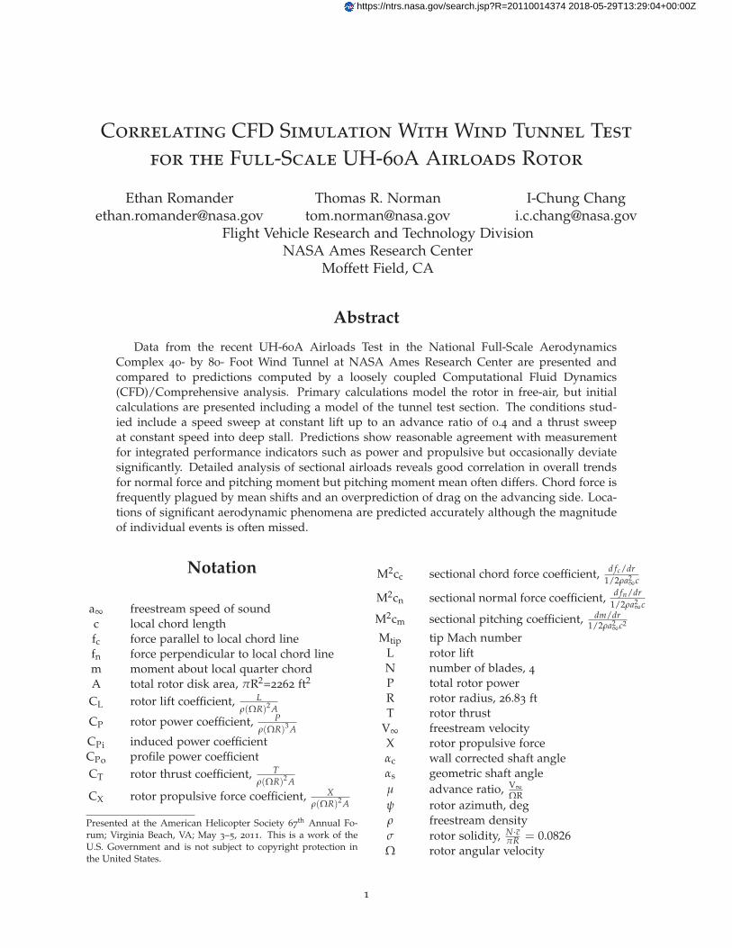
Figure 1 – UH-60A Airloads Rotor in 40- by 80-Foot Wind Tunnel.
Introduction
Testing was successfully completed in May2010 on a full-scale UH-60A rotor system in theUSAF’s National Full-Scale Aerodynamics Com-plex (NFAC) 40- by 80-Foot Wind Tunnel [1].The primary objective of this NASA/Army testprogram was to acquire a comprehensive set ofvalidation-quality measurements on a full-scalepressure-instrumented rotor system at conditionsthat challenge the most sophisticated modelingand simulation tools. A secondary objective wasto meet one of the original goals of the UH-60AAirloads program: to provide data to evaluate thesimilarity, or lack thereof, of measurements be-tween small-scale wind tunnel [2], full-scale windtunnel (current test), and full-scale flight test [3].
The test hardware included the same rotorblades used during the flight test. Figure 1 showsthese blades installed on the NFAC Large RotorTest Apparatus (LRTA) in the wind tunnel testsection. Key measurements included rotor per-formance, blade loads, blade pressures, blade dis-placements, and rotor wake measurements usinglarge-field Particle Image Velocimetry (PIV) andRetro-reflective Background Oriented Schlieren(RBOS).
Data were acquired over a wide range of testconditions, including speed sweeps at 1-g sim-ulated flight conditions and parametric thrustsweeps (up to and including stall) at various com-binations of shaft angles and forward speed. Theseconditions included airspeeds up to 175 kt andthrusts up to 32,000 lb. Data were also acquired
at matching conditions from the previous full-scaleflight test and small-scale DNW wind tunnel test toassess rotor and wind tunnel scaling issues. Finally,unique slowed-rotor simulations were performedat reduced RPM (40% and 65%), achieving advanceratios up to 1.0. A complete enumeration of dataacquired during the test is available in Ref. 1.
Unfortunately, not all test data is perfect and nosimulation is exact. The goal of this work is to pro-vide an initial correlation between measured dataand a state of the art simulation. This correlationis intended to help discover flaws in experimentaltechnique while at the same time identifying op-portunities to enhance rotorcraft simulation tech-nology.
Methodology
The complexity of rotorcraft aeromechanics isnot easily modeled. The analytical results pre-sented herein were obtained using two separatecodes—each a specialist in a particular aspect ofrotorcraft simulation—loosely joined for this pur-pose. This section will describe the two codes andhow they work together to maximize simulationaccuracy and efficiency.
CAMRAD II
CAMRAD II belongs to a family of softwareknown as “Comprehensive Codes” for the analysisof rotorcraft. These analyses incorporate a myriadof models to simulate the different aeromechani-cal subsystems of rotorcraft. CAMRAD II bringstogether a multibody dynamics model, a nonlin-ear finite elements structural model, and an aero-dynamics model based on lifting line theory [4].CAMRAD II has seen a great deal of use in thesimulation of the UH-60 aircraft in a variety offlight conditions [5–9].
The CAMRAD II structural dynamics model forthe UH-60A has been decades in development byNASA and the U.S. Army. The specific model usedhere was refined by Yeo et al. in 2004 [10]. Themodel simulated the rotor using 7 1-D structuralbeam elements and 20 aerodynamic panels. The ro-tor was trimmed using Newton-Raphson iterationon collective and cyclic to meet specified trim tar-gets.
2
OVERFLOW 2
All Navier-Stokes CFD analysis presented hereinwas performed using OVERFLOW 2 version 2.2b[11]. OVERFLOW 2 is an overset, structured-meshflow solver developed at NASA. For two decadesthe OVERFLOW solver has served to analyze avariety of rotorcraft under a wide range of flightconditions [12]. OVERFLOW 2 offers a wide vari-ety of numerical schemes, turbulence models, andboundary conditions. For the present study, OVER-FLOW 2 was run with 4th order central differencingand 4th order artificial dissipation in space. Timemarching was performed using a 2nd order dualtimestepping scheme. Turbulence was modelednear blade surfaces using the Spalart-Almaras one-equation model with rotational corrections. Theturbulence model was deactivated in regions onechord length or further from the rotor blades toreduce numerical dissipation of the wake. Bladesurfaces were modeled as viscous, adiabatic walls;outer boundaries were modeled using a character-istic condition imposing freestream quantities.
OVERFLOW 2 computes the flowfield by dis-cretizing the Navier-Stokes equations on a series ofoverset, structured grids. Grids modeling the ro-tor blades were body-fitted and curvilinear. Thesegrids, often called near-body grids, extended ap-proximately one chord length from the blade sur-face. The near-body grids were nested within oneor more grids, called off-body grids, which filledthe space between the rotor and the boundary ofthe computational domain. The OVERFLOW 2model included a notional hub, but the LRTA andwind tunnel struts were not modeled. All gridsexchanged flow information in regions of overlap.The amount of this overlap was sufficient to sup-port full 4th order accuracy at the boundaries.
The grid surface is the latest definition derivedfrom the as-built CAD model. Notable differencesbetween this surface definition and that of prior in-vestigations [14,15] are an outboard shift of the trimtab by approximately 4 inches, a small bump on theupper surface near the blade grip, a slight thinningof the airfoil very near the tip, and a blunt trailingedge across the whole span.
The near-body grid representing the bulk ofeach rotor blade had an “O” topology with 157points wrapping around the blade chordwise, 145points along the blade span, and 75 points nor-mal to the surface. The initial spacing at the bladesurface had a y+ value of 1. This grid system is
illustrated in Fig. 2. The baseline near-body gridsystem (the hub and all four blades) containedapproximately 10.7 million points.
Two different off-body grid systems providedtwo different simulation scenarios:
The first system used a series of ever largerCartesian grids to create shells expanding outwardfrom the near-body grid set. The grid point spacingwithin each shell is twice that of the shell imme-diately preceding it. The finest off-body grid hada spacing equivalent to 0.1 tip-chord lengths inall three directions. Seven such shells created acubic computational domain spanning ten rotorradii in every direction. Domain boundaries inthis scenario were set to a freestream characteristiccondition thereby simulating a rotor operating infree air. Flow in the off-body grids was treated asinviscid and the turbulence model was deactivated.This off-body grid set consisted of 15.5 million gridpoints and is depicted in Fig. 3.
The second off-body grid system used a sin-gle grid to envelop the near-body grid-set forminga computational domain that mimicked the sizeand shape of the wind tunnel test section. Thisgrid made no attempt to model the contraction orexpansion sections of the tunnel but rather main-tained the test section profile for 4.6 rotor radiiupstream and downstream. The rotor plane waslocated 20.4 feet above the simulated tunnel floor.The inlet end of the tunnel grid employed thesame freestream characteristic boundary conditionas the free air system, and the outlet plane useda boundary condition that ensured conservationof mass within the tunnel grid. Viscous terms ofthe Navier-Stokes equations were discarded forthis grid. This paradigm was initially proposed byChang et al. [16] This off-body grid contained 4.2million grid points and is pictured in Fig. 4.
In addition, a refined version of the free-air gridsystem was prepared to ascertain grid convergenceof the simulation. This grid system reduced gridpoint spacing in both the near-body and off-body,approximately doubling the number of grid pointsto 50.7 million.
Unless otherwise indicated, all predicted datapresented herein were computed using the baselinenear-body grid and the baseline free-air off-bodygrid set. This near-body and off-body combinationtotals 26.2 million grid points. To reduce computa-tion time CFD simulations were run using a hybriddistributed/shared memory scheme with 160 Mes-
3
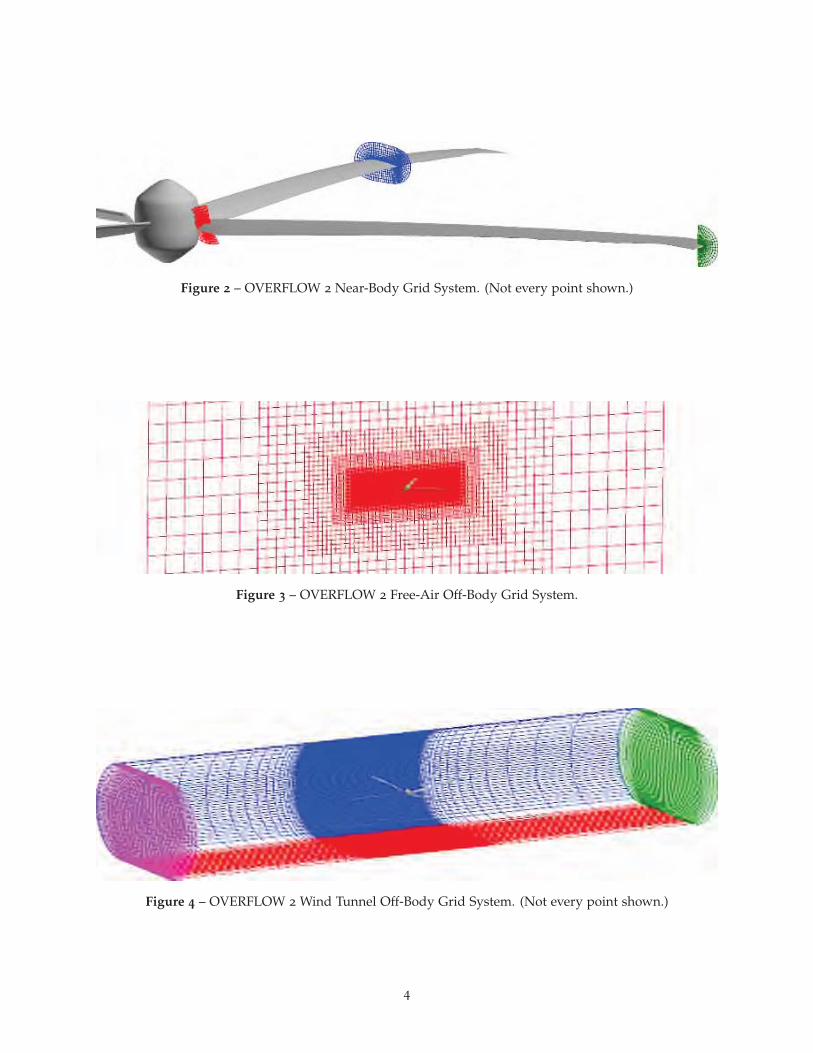
Figure 2 – OVERFLOW 2 Near-Body Grid System. (Not every point shown.)
Figure 3 – OVERFLOW 2 Free-Air Off-Body Grid System.
Figure 4 – OVERFLOW 2 Wind Tunnel Off-Body Grid System. (Not every point shown.)
4

sage Passing Interface (distributed memory) ranksand eight OpenMP threads (shared memory) perMPI rank for a total of 1280 parallel tasks. OVER-FLOW 2 required approximately 31 minutes to ad-vance the solution for this configuration ¼ of a ro-tor revolution using 1280 CPUs of an SGI Altix ICEcomputer.
Coupling Methodology
CAMRAD II uses a lower-fidelity aerodynamicsmodel than that available in modern CFD codes,and most CFD codes lack the sophisticated Com-putational Structural Dynamics (CSD) and trim ca-pabilities of comprehensive codes like CAMRAD II.Coupling a CFD code (e.g. OVERFLOW 2) to acomprehensive code (e.g. CAMRAD II) marries thestrengths of the two approaches and produces thehighest-fidelity solution currently possible. For thisstudy, coupling is achieved by alternate executionof OVERFLOW 2 and CAMRAD II. At the end ofeach code’s turn to execute, it passes data to thenext code. The data passed from OVERFLOW 2to CAMRAD II is airload data integrated from itsNavier-Stokes model of the UH-60 rotor. This air-load data is used to augment CAMRAD II’s inter-nal aerodynamics model (which consists of airfoiltables and a lower-order wake model). At the endof its execution, CAMRAD II generates updatedcontrol positions and a description of how the bladedeforms elastically as it revolves around the shaft.These quantities are used to give OVERFLOW 2’sgrids a realistic motion in response to the aero-dynamic environment. This algorithm, called thedelta coupling technique, was pioneered by Tung etal. [13] and implemented in OVERFLOW by Pots-dam et al. [14] Significantly improved airloads pre-diction capability has been demonstrated for theUH-60A rotor in steady level flight conditions us-ing this loosely coupled approach [14, 15].
The CFD solution is advanced ¼ revolution dur-ing a coupling iteration because this allows eachof the rotor’s four blades to sweep through a fullquadrant of the rotor disk. Taken in aggregate, thefour blades thereby determine the airloads at everyazimuth for every coupling iteration.
Convergence of the coupling process was deter-mined by monitoring blade airloads for periodic-ity. When the airloads did not vary significantlyfrom one coupling iteration to the next, the solu-tion was judged to be converged. For the present
analysis, this generally occurred after 24 couplingiterations. Since OVERFLOW 2 was allowed to it-erate for ¼ revolution between coupling exchanges,this equates to 6 full revolutions for the convergedsolution. A fully converged coupled solution re-quired approximately 17 hours to compute for thebaseline grid on 1280 SGI Altix ICE processors.
Selected Test Conditions And Trim Ap-proach
For the present investigation, two parametricsweeps were selected for analysis. First, a speedsweep was selected to test simulation accuracy overa wide range of advance ratios. Second, a thrustsweep was selected to test simulation accuracy un-der conditions ranging from a lightly loaded rotorthrough deep stall.
The selected speed sweep ranged from μ=0.15to 0.4 with a constant CL/σ=0.09 and a constant tipMach number of 0.65. During testing, lift, propul-sive force, and hub moments were trimmed tomatch nominal values at each flight condition byvarying αs along with collective and cyclic pitch.In CFD calculations it is difficult to change theshaft angle once it has been set, which compli-cates its use as a trim control in adjusting lift andpropulsive force. Instead, these flight conditionswere matched in simulation by setting a constantαs as indicated by tunnel data while trimming CTand hub moments to match tunnel values usingcollective and cyclic pitch.
The selected thrust sweep was conducted atμ=0.3 with Mtip = 0.625, αs = 0◦, and the rotortrimmed for minimum hub moments. The thrustwas varied by changes in collective pitch up tostall. Absolute collective angles for a given thrustare generally different between simulation and test.To nullify this offset, a baseline case was selectedat CT/σ=0.08 and the simulation was trimmed tomatch the measured thrust. Collective deltas werederived from test data relative to this baseline andthen applied to the simulated baseline to producethe remaining target points.
In all cases, free-air simulations used correctedshaft angles, αc, derived from the geometric shaftangle, αs, by applying a Prandtl-Glauert wall cor-rection [1]. Simulations including tunnel walls useduncorrected shaft angle data.
5
Results
The 2010 UH-60A Airloads Test is a valuableresource not only for the breadth of flight condi-tions obtained but for the depth of detail availablein each measurement. Failure of analysis to pre-dict bulk loads accurately can be diagnosed by ex-ploring detailed measurements and how they com-pare to quantities extracted from simulation results.This approach will now be applied to the presentsimulation methodology first for the selected speedsweep and then for the selected thrust sweep.
Speed Sweep
Integrated Results
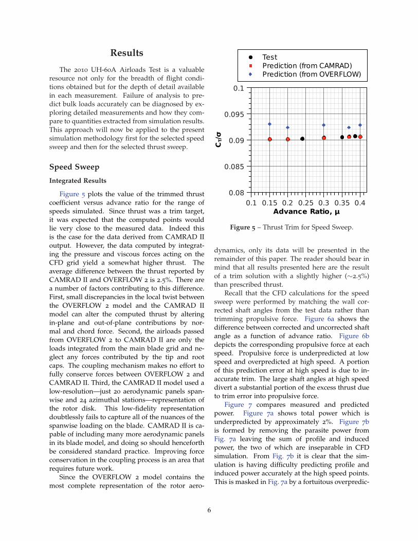
Figure 5 plots the value of the trimmed thrustcoefficient versus advance ratio for the range ofspeeds simulated. Since thrust was a trim target,it was expected that the computed points wouldlie very close to the measured data. Indeed thisis the case for the data derived from CAMRAD IIoutput. However, the data computed by integrat-ing the pressure and viscous forces acting on theCFD grid yield a somewhat higher thrust. Theaverage difference between the thrust reported byCAMRAD II and OVERFLOW 2 is 2.5%. There area number of factors contributing to this difference.First, small discrepancies in the local twist betweenthe OVERFLOW 2 model and the CAMRAD IImodel can alter the computed thrust by alteringin-plane and out-of-plane contributions by nor-mal and chord force. Second, the airloads passedfrom OVERFLOW 2 to CAMRAD II are only theloads integrated from the main blade grid and ne-glect any forces contributed by the tip and rootcaps. The coupling mechanism makes no effort tofully conserve forces between OVERFLOW 2 andCAMRAD II. Third, the CAMRAD II model used alow-resolution—just 20 aerodynamic panels span-wise and 24 azimuthal stations—representation ofthe rotor disk. This low-fidelity representationdoubtlessly fails to capture all of the nuances of thespanwise loading on the blade. CAMRAD II is ca-pable of including many more aerodynamic panelsin its blade model, and doing so should henceforthbe considered standard practice. Improving forceconservation in the coupling process is an area thatrequires future work.
Since the OVERFLOW 2 model contains themost complete representation of the rotor aero-
�
����
����
�����
����
�����
���
���� ��������
��� ���� ��� ���� �� ��� ��
�� �
������������������������
����������������� !"�#$ %�
Figure 5 – Thrust Trim for Speed Sweep.
dynamics, only its data will be presented in theremainder of this paper. The reader should bear inmind that all results presented here are the resultof a trim solution with a slightly higher (∼2.5%)than prescribed thrust.
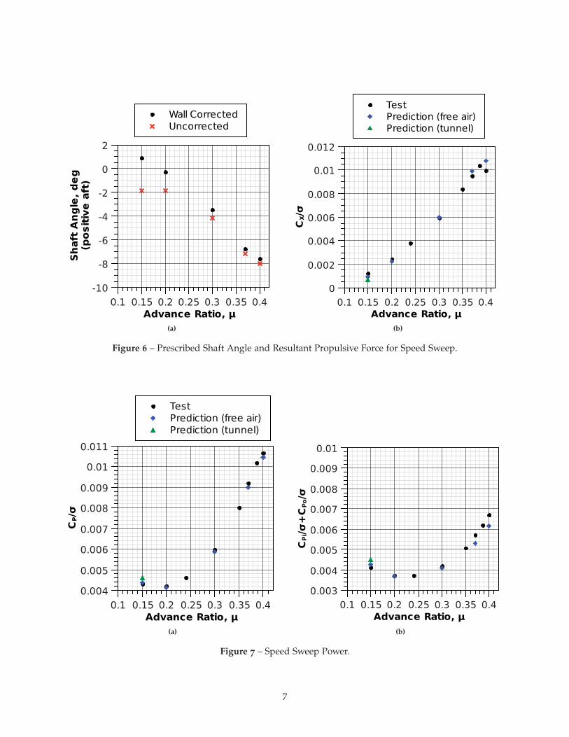
Recall that the CFD calculations for the speedsweep were performed by matching the wall cor-rected shaft angles from the test data rather thantrimming propulsive force. Figure 6a shows thedifference between corrected and uncorrected shaftangle as a function of advance ratio. Figure 6bdepicts the corresponding propulsive force at eachspeed. Propulsive force is underpredicted at lowspeed and overpredicted at high speed. A portionof this prediction error at high speed is due to in-accurate trim. The large shaft angles at high speeddivert a substantial portion of the excess thrust dueto trim error into propulsive force.
Figure 7 compares measured and predictedpower. Figure 7a shows total power which isunderpredicted by approximately 2%. Figure 7bis formed by removing the parasite power fromFig. 7a leaving the sum of profile and inducedpower, the two of which are inseparable in CFDsimulation. From Fig. 7b it is clear that the sim-ulation is having difficulty predicting profile andinduced power accurately at the high speed points.This is masked in Fig. 7a by a fortuitous overpredic-
6
�
����������� �
��������������
���
��
��
��
��
�
�
� ��������������
��� ��� ��� ��� �� �� ���
��������������
�����������
(a)
����
�
�����
�����
�����
�����
����
�����
��������������
��� ���� ��� ���� ��� ���� ���
�� �
�������������������
������������������
(b)
Figure 6 – Prescribed Shaft Angle and Resultant Propulsive Force for Speed Sweep.
�
����
�����
�����
�����
�����
�����
�����
����
�����
���� ��������
��� ���� ��� ���� �� ��� ���
��
������ ��������������
������ ����� ������
(a)
�
�������
����
�����
�����
�����
�����
�����
�����
�����
���
��� ����������
�� ��� �� ��� ��� ���� ���
(b)
Figure 7 – Speed Sweep Power.
7
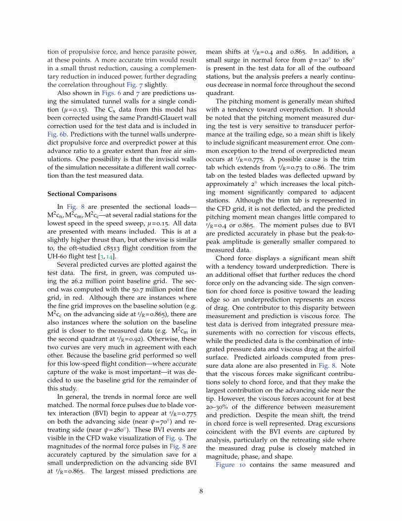
tion of propulsive force, and hence parasite power,at these points. A more accurate trim would resultin a small thrust reduction, causing a complemen-tary reduction in induced power, further degradingthe correlation throughout Fig. 7 slightly.
Also shown in Figs. 6 and 7 are predictions us-ing the simulated tunnel walls for a single condi-tion (μ=0.15). The Cx data from this model hasbeen corrected using the same Prandtl-Glauert wallcorrection used for the test data and is included inFig. 6b. Predictions with the tunnel walls underpre-dict propulsive force and overpredict power at thisadvance ratio to a greater extent than free air sim-ulations. One possibility is that the inviscid wallsof the simulation necessitate a different wall correc-tion than the test measured data.
Sectional Comparisons
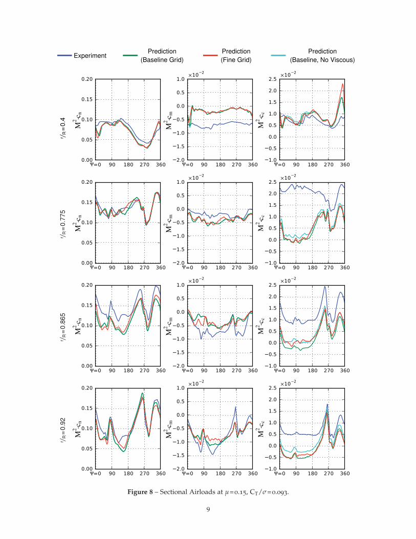
In Fig. 8 are presented the sectional loads—M2cn, M2cm, M2cc—at several radial stations for thelowest speed in the speed sweep, μ=0.15. All dataare presented with means included. This is at aslightly higher thrust than, but otherwise is similarto, the oft-studied c8513 flight condition from theUH-60 flight test [3, 14].
Several predicted curves are plotted against thetest data. The first, in green, was computed us-ing the 26.2 million point baseline grid. The sec-ond was computed with the 50.7 million point finegrid, in red. Although there are instances wherethe fine grid improves on the baseline solution (e.g.M2cc on the advancing side at r/R=0.865), there arealso instances where the solution on the baselinegrid is closer to the measured data (e.g. M2cm inthe second quadrant at r/R=0.92). Otherwise, thesetwo curves are very much in agreement with eachother. Because the baseline grid performed so wellfor this low-speed flight condition—where accuratecapture of the wake is most important—it was de-cided to use the baseline grid for the remainder ofthis study.
In general, the trends in normal force are wellmatched. The normal force pulses due to blade vor-tex interaction (BVI) begin to appear at r/R=0.775on both the advancing side (near ψ=70◦) and re-treating side (near ψ=280◦). These BVI events arevisible in the CFD wake visualization of Fig. 9. Themagnitudes of the normal force pulses in Fig. 8 areaccurately captured by the simulation save for asmall underprediction on the advancing side BVIat r/R=0.865. The largest missed predictions are
mean shifts at r/R=0.4 and 0.865. In addition, asmall surge in normal force from ψ=120◦ to 180◦is present in the test data for all of the outboardstations, but the analysis prefers a nearly continu-ous decrease in normal force throughout the secondquadrant.
The pitching moment is generally mean shiftedwith a tendency toward overprediction. It shouldbe noted that the pitching moment measured dur-ing the test is very sensitive to transducer perfor-mance at the trailing edge, so a mean shift is likelyto include significant measurement error. One com-mon exception to the trend of overpredicted meanoccurs at r/R=0.775. A possible cause is the trimtab which extends from r/R=0.73 to 0.86. The trimtab on the tested blades was deflected upward byapproximately 2◦ which increases the local pitch-ing moment significantly compared to adjacentstations. Although the trim tab is represented inthe CFD grid, it is not deflected, and the predictedpitching moment mean changes little compared tor/R=0.4 or 0.865. The moment pulses due to BVIare predicted accurately in phase but the peak-to-peak amplitude is generally smaller compared tomeasured data.
Chord force displays a significant mean shiftwith a tendency toward underprediction. There isan additional offset that further reduces the chordforce only on the advancing side. The sign conven-tion for chord force is positive toward the leadingedge so an underprediction represents an excessof drag. One contributor to this disparity betweenmeasurement and prediction is viscous force. Thetest data is derived from integrated pressure mea-surements with no correction for viscous effects,while the predicted data is the combination of inte-grated pressure data and viscous drag at the airfoilsurface. Predicted airloads computed from pres-sure data alone are also presented in Fig. 8. Notethat the viscous forces make significant contribu-tions solely to chord force, and that they make thelargest contribution on the advancing side near thetip. However, the viscous forces account for at best20–30% of the difference between measurementand prediction. Despite the mean shift, the trendin chord force is well represented. Drag excursionscoincident with the BVI events are captured byanalysis, particularly on the retreating side wherethe measured drag pulse is closely matched inmagnitude, phase, and shape.
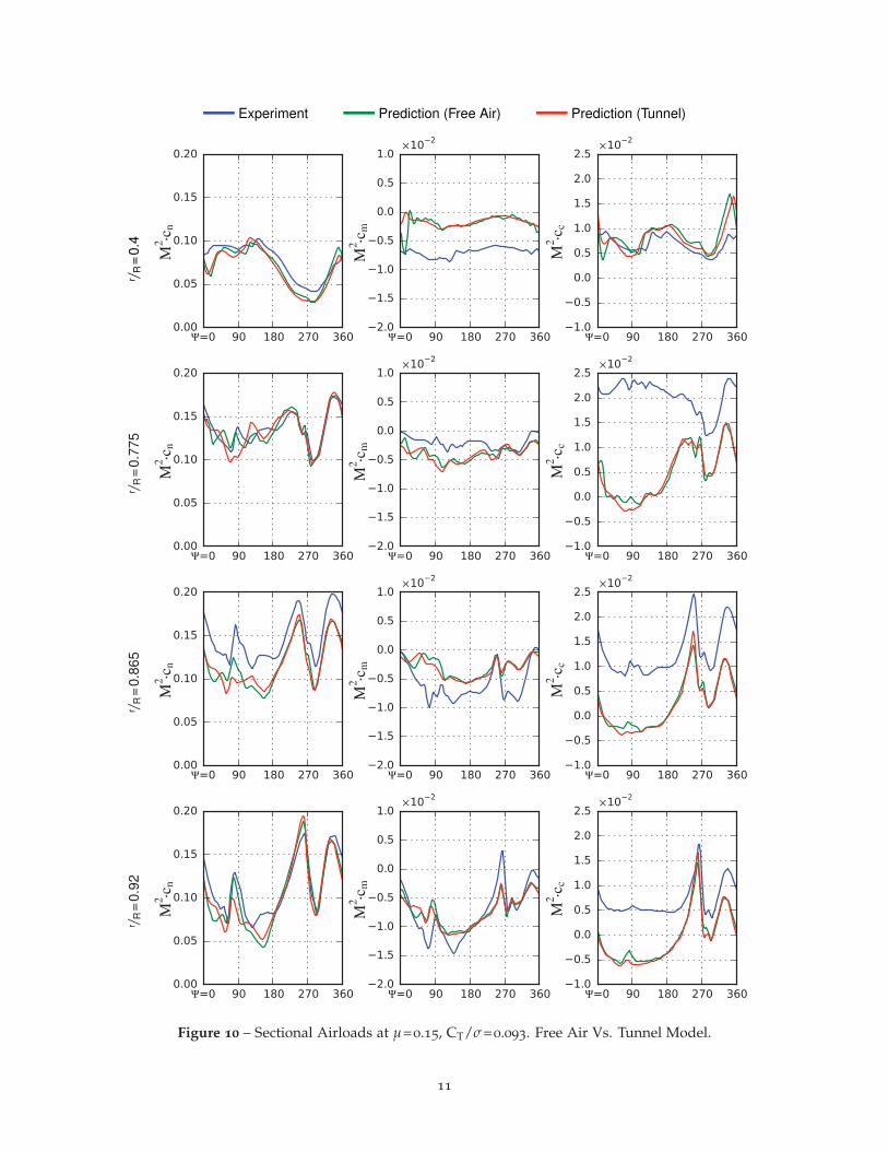
Figure 10 contains the same measured and
8
ExperimentPrediction
(Baseline Grid)Prediction(Fine Grid)
Prediction(Baseline, No Viscous)
r / R=
0.4
r / R=
0.77
5r / R
=0.
865
r / R=
0.92
Figure 8 – Sectional Airloads at μ=0.15, CT/σ=0.093.
9
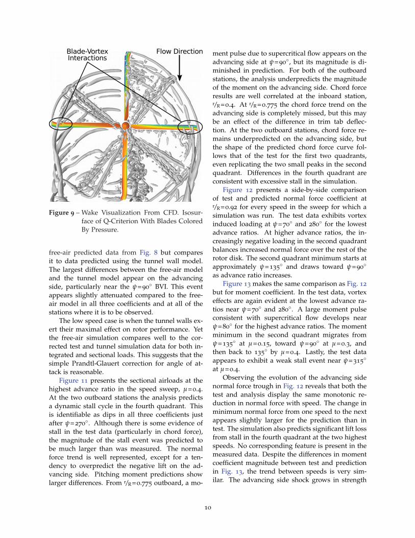
Figure 9 – Wake Visualization From CFD. Isosur-face of Q-Criterion With Blades ColoredBy Pressure.
free-air predicted data from Fig. 8 but comparesit to data predicted using the tunnel wall model.The largest differences between the free-air modeland the tunnel model appear on the advancingside, particularly near the ψ=90◦ BVI. This eventappears slightly attenuated compared to the free-air model in all three coefficients and at all of thestations where it is to be observed.
The low speed case is when the tunnel walls ex-ert their maximal effect on rotor performance. Yetthe free-air simulation compares well to the cor-rected test and tunnel simulation data for both in-tegrated and sectional loads. This suggests that thesimple Prandtl-Glauert correction for angle of at-tack is reasonable.
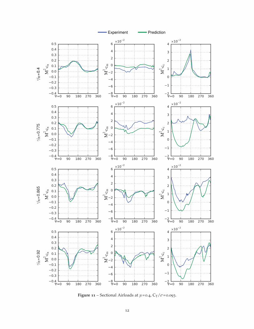
Figure 11 presents the sectional airloads at thehighest advance ratio in the speed sweep, μ=0.4.At the two outboard stations the analysis predictsa dynamic stall cycle in the fourth quadrant. Thisis identifiable as dips in all three coefficients justafter ψ=270◦. Although there is some evidence ofstall in the test data (particularly in chord force),the magnitude of the stall event was predicted tobe much larger than was measured. The normalforce trend is well represented, except for a ten-dency to overpredict the negative lift on the ad-vancing side. Pitching moment predictions showlarger differences. From r/R=0.775 outboard, a mo-
ment pulse due to supercritical flow appears on theadvancing side at ψ=90◦, but its magnitude is di-minished in prediction. For both of the outboardstations, the analysis underpredicts the magnitudeof the moment on the advancing side. Chord forceresults are well correlated at the inboard station,r/R=0.4. At r/R=0.775 the chord force trend on theadvancing side is completely missed, but this maybe an effect of the difference in trim tab deflec-tion. At the two outboard stations, chord force re-mains underpredicted on the advancing side, butthe shape of the predicted chord force curve fol-lows that of the test for the first two quadrants,even replicating the two small peaks in the secondquadrant. Differences in the fourth quadrant areconsistent with excessive stall in the simulation.
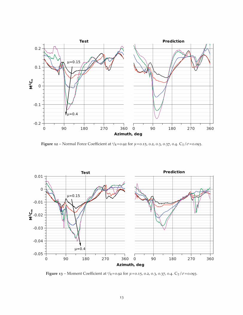
Figure 12 presents a side-by-side comparisonof test and predicted normal force coefficient atr/R=0.92 for every speed in the sweep for which asimulation was run. The test data exhibits vortexinduced loading at ψ=70◦ and 280◦ for the lowestadvance ratios. At higher advance ratios, the in-creasingly negative loading in the second quadrantbalances increased normal force over the rest of therotor disk. The second quadrant minimum starts atapproximately ψ=135◦ and draws toward ψ=90◦as advance ratio increases.
Figure 13 makes the same comparison as Fig. 12but for moment coefficient. In the test data, vortexeffects are again evident at the lowest advance ra-tios near ψ=70◦ and 280◦. A large moment pulseconsistent with supercritical flow develops nearψ=80◦ for the highest advance ratios. The momentminimum in the second quadrant migrates fromψ=135◦ at μ=0.15, toward ψ=90◦ at μ=0.3, andthen back to 135◦ by μ=0.4. Lastly, the test dataappears to exhibit a weak stall event near ψ=315◦at μ=0.4.
Observing the evolution of the advancing sidenormal force trough in Fig. 12 reveals that both thetest and analysis display the same monotonic re-duction in normal force with speed. The change inminimum normal force from one speed to the nextappears slightly larger for the prediction than intest. The simulation also predicts significant lift lossfrom stall in the fourth quadrant at the two highestspeeds. No corresponding feature is present in themeasured data. Despite the differences in momentcoefficient magnitude between test and predictionin Fig. 13, the trend between speeds is very sim-ilar. The advancing side shock grows in strength
10
Experiment Prediction (Free Air) Prediction (Tunnel)r / R
=0.
4r / R
=0.
775
r / R=
0.86
5r / R
=0.
92
Figure 10 – Sectional Airloads at μ=0.15, CT/σ=0.093. Free Air Vs. Tunnel Model.
11
Experiment Predictionr / R
=0.
4r / R
=0.
775
r / R=
0.86
5r / R
=0.
92
Figure 11 – Sectional Airloads at μ=0.4, CT/σ=0.093.
12
�� �� ��� ��� ���
����������
��
���
���
�
��
��
�� � ��� ��� ���
�� �
����
����
������������
Figure 12 – Normal Force Coefficient at r/R=0.92 for μ=0.15, 0.2, 0.3, 0.37, 0.4. CT/σ=0.093.
�� � ��� ��� ���
����������
�
���
����
����
����
����
�
���
�� � ��� ��� ���
����
���
���
��� ��������
Figure 13 – Moment Coefficient at r/R=0.92 for μ=0.15, 0.2, 0.3, 0.37, 0.4. CT/σ=0.093.
13
and migrates toward ψ=90◦. The moment troughbehind the shock also evolves very similarly acrossthe speed range. Differences include an expansionof the trough into the third quadrant for the pre-dicted data, the prediction of a stall cycle at μ=0.37when none is present in measured data, and anenhancement of the predicted stall cycle at μ=0.4compared to measurement.
Thrust Sweep
Integrated Results
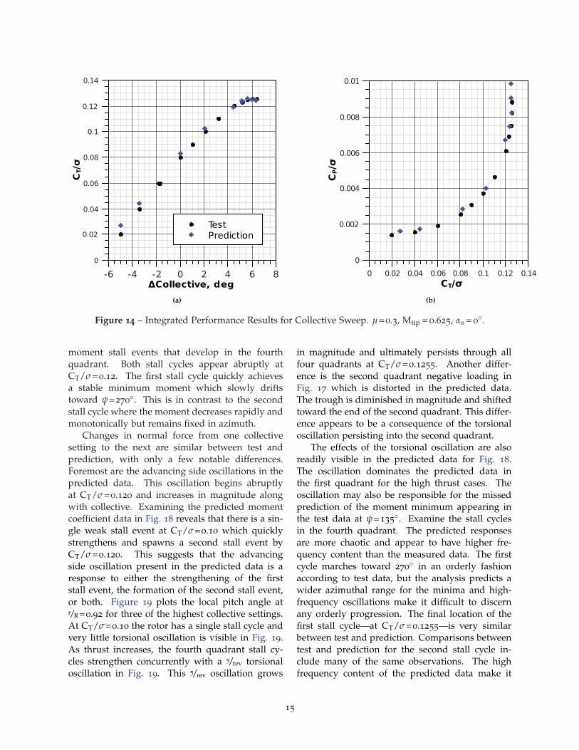
Presented in Fig. 14 are the predicted perfor-mance results for the selected thrust sweep. Fromthis figure it is clear that the analysis performs wellat predicting the maximum rotor thrust and the re-lationship between power and thrust throughoutthe sweep. Recall that the analysis was trimmedto match thrust at the CT/σ=0.08 point but thatin general CFD integrated thrust is slightly higherthan specified. This leads to a small thrust surplusthroughout the linear region since all collective an-gles are set relative to the baseline condition. Athigh collectives the excess thrust vanishes becausethe rotor is stalled and appears incapable of pro-ducing more thrust. The analysis also exhibits re-duced sensitivity to collective change evidenced byan approximately 7% reduction of slope in the lin-ear region.
Power is generally overpredicted, with differ-ences up to 11% at the highest thrust conditions(Fig. 14b). The fact that the predicted and measuredpoints lie on very similar curves, however, suggeststhat if thrust was rigorously matched, power maybe better predicted.
Sectional Comparisons
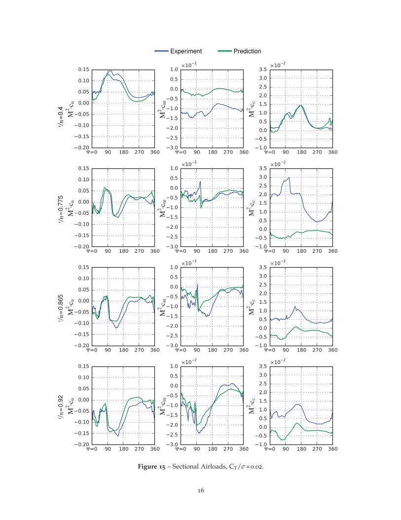
Sectional airloads for the minimum collectivesetting are presented in Fig. 15. At this collective,the measured thrust was CT/σ=0.02. The normalforce bucket in the second quadrant is narrowerand shallower in prediction than in test. Normalforce is also slightly overpredicted for the majorityof the retreating side, except at the inboard station.Moment coefficient mean is well predicted at thiscondition—except at r/R=0.4—but there exist sig-nificant differences in trends between analysis andtest. For example, there is a shock-induced mo-ment pulse that appears in the second quadrantat r/R=0.775, migrates toward the first quadrant,
and ends in an interesting double pulse at r/R=0.92.Although the phase of these pulses is well corre-lated, the peak-to-peak magnitude of the predictedpulses is smaller. Moment recovery following theshocks also begins too early and progresses slowlycompared to measurement for r/R=0.865 and 0.92.Chord force continues to be mean shifted outboardof r/R=0.775, and the trend is completely mispre-dicted at r/R=0.775.
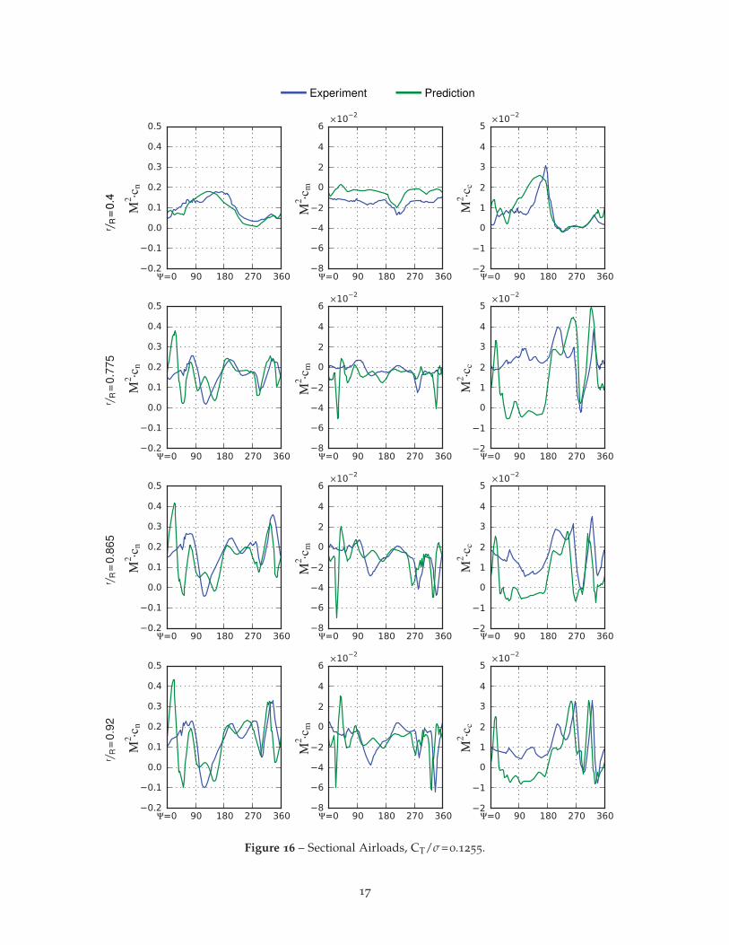
The sectional airloads presented in Fig. 16are for the maximum collective condition whereCT/σ=0.1255. Comparisons at this condition mustbe tempered with the knowledge that stall is bynature a chaotic phenomena and there exists con-siderable variation in loading from one revolutionto another, even in simulation. Test data in Fig. 16are average loads sampled from 128 revolutions,but computing an ensemble average from CFD isimpractical. The predicted data provided in Fig. 16are instead single-revolution snapshots.
The flow at the inboard station remains rela-tively benign and correlation is good. The mostsignificant deviations are a familiar mean shift inpitching moment and a blunting of the chord forcepeak in the second quadrant. Outboard, the load-ing is dominated by two severe stall cycles clearlyindicated near the forth quadrant. The analysis ap-pears to phase shift the stall cycles slightly, pre-dicting both events perhaps 15◦ earlier than mea-sured in test. Despite the phase shift, the magni-tudes of the stall events are well predicted. Oneglaring difference at this deeply stalled conditionis a large first-quadrant excursion in all three coef-ficients for the prediction. The similarity betweenthe frequency of this event and the torsional modeof the blade suggests that it is a torsional responseto the fourth quadrant stall cycles.
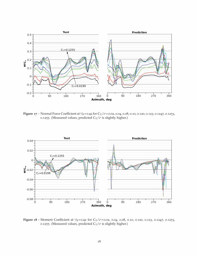
Figure 17 compares sectional normal force atr/R=0.92 for all collective settings simulated. Theexperiment observed an interesting evolution ofnormal force in the second quadrant. The normalforce increased with collective until CT/σ=0.12 af-ter which it began to decrease, forming a narrowtrough at approximately ψ=120◦. The normal forcereduction beginning at CT/σ=0.12 is necessary tomaintain roll balance across the rotor. Also visi-ble in the test data is the development of two stallcycles, one at ψ=290◦ and the second at 340◦.
Figure 18 presents moment coefficient at r/R=0.92for all collective settings simulated. The mostprominent features in the test data are the two
14
����
�
����
����
����
����
���
����
����
���������������� �� �� � � � � �
��
��� �����
(a)
� ��
�
�����
�����
�����
�����
����
����� ���� ���� ���� ���� ��� ���� ����
(b)
Figure 14 – Integrated Performance Results for Collective Sweep. μ=0.3, Mtip = 0.625, αs = 0◦.
moment stall events that develop in the fourthquadrant. Both stall cycles appear abruptly atCT/σ=0.12. The first stall cycle quickly achievesa stable minimum moment which slowly driftstoward ψ=270◦. This is in contrast to the secondstall cycle where the moment decreases rapidly andmonotonically but remains fixed in azimuth.
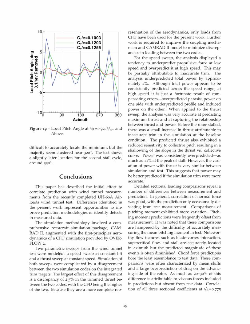
Changes in normal force from one collectivesetting to the next are similar between test andprediction, with only a few notable differences.Foremost are the advancing side oscillations in thepredicted data. This oscillation begins abruptlyat CT/σ=0.120 and increases in magnitude alongwith collective. Examining the predicted momentcoefficient data in Fig. 18 reveals that there is a sin-gle weak stall event at CT/σ=0.10 which quicklystrengthens and spawns a second stall event byCT/σ=0.120. This suggests that the advancingside oscillation present in the predicted data is aresponse to either the strengthening of the firststall event, the formation of the second stall event,or both. Figure 19 plots the local pitch angle atr/R=0.92 for three of the highest collective settings.At CT/σ=0.10 the rotor has a single stall cycle andvery little torsional oscillation is visible in Fig. 19.As thrust increases, the fourth quadrant stall cy-cles strengthen concurrently with a 5/rev torsionaloscillation in Fig. 19. This 5/rev oscillation grows
in magnitude and ultimately persists through allfour quadrants at CT/σ=0.1255. Another differ-ence is the second quadrant negative loading inFig. 17 which is distorted in the predicted data.The trough is diminished in magnitude and shiftedtoward the end of the second quadrant. This differ-ence appears to be a consequence of the torsionaloscillation persisting into the second quadrant.
The effects of the torsional oscillation are alsoreadily visible in the predicted data for Fig. 18.The oscillation dominates the predicted data inthe first quadrant for the high thrust cases. Theoscillation may also be responsible for the missedprediction of the moment minimum appearing inthe test data at ψ=135◦. Examine the stall cyclesin the fourth quadrant. The predicted responsesare more chaotic and appear to have higher fre-quency content than the measured data. The firstcycle marches toward 270◦ in an orderly fashionaccording to test data, but the analysis predicts awider azimuthal range for the minima and high-frequency oscillations make it difficult to discernany orderly progression. The final location of thefirst stall cycle—at CT/σ=0.1255—is very similarbetween test and prediction. Comparisons betweentest and prediction for the second stall cycle in-clude many of the same observations. The highfrequency content of the predicted data make it
15
Experiment Predictionr / R
=0.
4r / R
=0.
775
r / R=
0.86
5r / R
=0.
92
Figure 15 – Sectional Airloads, CT/σ=0.02.
16
Experiment Predictionr / R
=0.
4r / R
=0.
775
r / R=
0.86
5r / R
=0.
92
Figure 16 – Sectional Airloads, CT/σ=0.1255.
17
�� �� ��� ��� ���
���������
��
�
���
���
�
��
��
��
��
���
�� �� ��� �� ��
���
������������
� �������
� �������
Figure 17 – Normal Force Coefficient at r/R=0.92 for CT/σ=0.02, 0.04, 0.08, 0.10, 0.120, 0.123, 0.1247, 0.1253,0.1255. (Measured values, predicted CT/σ is slightly higher.)
�� �� ��� �� ��
���������
��
�����
�����
�����
�����
�
����
����
�� �� ��� �� ��
����
��� ��������
���������
���������
Figure 18 – Moment Coefficient at r/R=0.92 for CT/σ=0.02, 0.04, 0.08, 0.10, 0.120, 0.123, 0.1247, 0.1253,0.1255. (Measured values, predicted CT/σ is slightly higher.)
18
Azimuth
Loca
lPitc
hAngle,
deg
0,1/rev
Rem
oved
0 90 180 270 360-10
-5
0
5
10
CT/σ=0.1003CT/σ=0.1203CT/σ=0.1255
Figure 19 – Local Pitch Angle at r/R=0.92, 2/rev andAbove.
difficult to accurately locate the minimum, but themajority seem clustered near 320◦. The test showsa slightly later location for the second stall cycle,around 330◦.
Conclusions
This paper has described the initial effort tocorrelate prediction with wind tunnel measure-ments from the recently completed UH-60A Air-loads wind tunnel test. Differences identified inthe present work represent opportunities to im-prove prediction methodologies or identify defectsin measured data.
The simulation methodology involved a com-prehensive rotorcraft simulation package, CAM-RAD II, augmented with the first-principles aero-dynamics of a CFD simulation provided by OVER-FLOW 2.
Two parametric sweeps from the wind tunneltest were modeled: a speed sweep at constant liftand a thrust sweep at constant speed. Simulation ofboth sweeps were complicated by a disagreementbetween the two simulation codes on the integratedtrim targets. The largest effect of this disagreementis a discrepancy of 2.5% in the trimmed thrust be-tween the two codes, with the CFD being the higherof the two. Because they are a more complete rep-
resentation of the aerodynamics, only loads fromCFD have been used for the present work. Furtherwork is required to improve the coupling mecha-nism and CAMRAD II model to minimize discrep-ancies in loading between the two codes.
For the speed sweep, the analysis displayed atendency to underpredict propulsive force at lowspeed and overpredict it at high speed. This maybe partially attributable to inaccurate trim. Theanalysis underpredicted total power by approxi-mately 2%. Although total power appears to beconsistently predicted across the speed range, athigh speed it is just a fortunate result of com-pensating errors—overpredicted parasite power onone side with underpredicted profile and inducedpower on the other. When applied to the thrustsweep, the analysis was very accurate at predictingmaximum thrust and at capturing the relationshipbetween thrust and power. Before the rotor stalled,there was a small increase in thrust attributable toinaccurate trim in the simulation at the baselinecondition. The predicted thrust also exhibited areduced sensitivity to collective pitch resulting in ashallowing of the slope in the thrust vs. collectivecurve. Power was consistently overpredicted—asmuch as 11% at the peak of stall. However, the vari-ation of power with thrust is very similar betweensimulation and test. This suggests that power maybe better predicted if the simulation trim were moreaccurate.
Detailed sectional loading comparisons reveal anumber of differences between measurement andprediction. In general, correlation of normal forcewas good, with the prediction only occasionally de-viating from test measurement. Comparisons ofpitching moment exhibited more variation. Pitch-ing moment predictions were frequently offset frommeasurement. It was noted that these comparisonsare hampered by the difficulty of accurately mea-suring the mean pitching moment in test. Notewor-thy flow features such as blade-vortex interaction,supercritical flow, and stall are accurately locatedin azimuth but the predicted magnitude of theseevents is often diminished. Chord force predictionsbore the least resemblance to test data. These com-parisons were often characterized by mean shiftsand a large overprediction of drag on the advanc-ing side of the rotor. As much as 20–30% of thisdifference is attributable to viscous forces includedin predictions but absent from test data. Correla-tion of all three sectional coefficients at r/R=0.775
19
may be improved by correctly modeling trim tabdeflection.
Other observed trends included a tendency forthe analysis to overpredict the severity of stall, fre-quently predicting it at lower advance ratio and fur-ther inboard on the blade than indicated by mea-surement. Individual stall events are not as welldefined in prediction as in test and their azimuthallocations do not progress smoothly as thrust in-creases. Also, for flows exhibiting a shock at ornear ψ=90◦, the moment trough that formed in thesecond quadrant just after the shock generally ex-tended into the third quadrant according to simu-lation, but the corresponding feature was confinedto the second quadrant in the test.
One final observation was made only for thedeeply stalled cases of the thrust sweep. The analy-sis predicted a large oscillation in all three sectionalcoefficients beginning in the first quadrant and per-sisting into the second. No such excursion waspresent in the measured data. This has been shownto be a torsional response of the blade model to theformation of stall cycles in the fourth quadrant.
Modeling wind tunnel walls in the CFD simu-lation made only small differences in the sectionalloads at μ=0.15. The largest differences were on theadvancing side near the ψ=90◦ BVI. Larger differ-ences were observed in the integrated performanceparameters, with the free-air model outperformingthe tunnel model. Further work is required to de-termine if this is a trend or merely an isolated mis-prediction.
The goal of this work was to provide an ini-tial correlation with the newest data from the U.S.Army/NASA UH-60 test program. This dataset isof tremendous value to the rotorcraft communityfor the breadth of flight conditions sampled andthe variety of detailed measurements made at each.No significant anomalies were identified in the testdata studied, but the correlation effort revealed anumber of areas for improvement in the simulationtechnique. Development is required to improvethe coupling mechanics between CAMRAD II andOVERFLOW 2. Better force transfer between thetwo is mandatory for improving trim accuracy andaccurately predicting integrated loads. Accuratepower prediction remains a challenge for analysis.More detailed investigation is necessary to identifythe cause of the stall-related torsional oscillationin the blade model and to improve the capture ofsectional loading details such as dynamic stall and
the effects of supercritical flow.
References
[1] Norman, T.R., Shinoda, P., Peterson, R.L., andDatta, A., “Full-Scale Wind Tunnel Test ofthe UH-60A Airloads Rotor”, American Heli-copter Society 67th Annual Forum, May 2011.
[2] Lorber, P.F., “Aerodynamic Results of aPressure-Instrumented Model Rotor Test at theDNW”, Journal of the American Helicopter Soci-ety, Vol. 36, No. 4, October 1991.
[3] Kufeld, R.M., Balough, D.L., Cross, J.L., et al.,“Flight Testing of the UH-60A Airloads Air-craft”, American Helicopter Society 50th An-nual Forum, May 1994.
[4] Johnson, W., “Technology Drivers in the De-velopment of CAMRAD II”, American Heli-copter Society Aeromechanics Specialist Meet-ing, San Francisco, CA, January 19-21, 1994.
[5] Yeo, H., Bousman, W.G., and Johnson, W.,“Performance Analysis of a Utility Helicopterwith Standard and Advanced Rotor”, Journalof the American Helicopter Society, Vol. 49, No. 3,July 2004, pp. 250–270.
[6] Shinoda, P.M., Yeo, H., and Norman, T.R., “Ro-tor Performance of a UH-60 Rotor System inthe NASA Ames 80- by 120-Foot Wind Tun-nel”, Journal of the American Helicopter Society,Vol. 49, No. 4, October 2004.
[7] Yeo, H., and Johnson, W., “Assessment ofComprehensive Analysis Calculation of Air-loads on Helicopter Rotors”, Journal of Aircraft,Vol. 42, No. 5, September–October 2005.
[8] Yeo, H., and Johnson, W., “Prediction of RotorStructural Loads with Comprehensive Analy-sis”, Journal of the American Helicopter Society,Vol. 53, No. 2, April 2008.
[9] Yeo, H., Romander, E., and Norman, T., “In-vestigation of Rotor Performance and Loads ofa UH-60A Individual Blade Control System”,American Helicopter Society 66th Annual Fo-rum, Phoenix, AZ, May 11–13, 2010.
[10] Yeo, H., Bousman, W.G., and Johnson, W.,“Performance Analysis of a Utility Helicopter
20
with Standard and Advanced Rotor”, Journalof the American Helicopter Society, Vol. 49, No. 3,July 2004, pp. 250–270.
[11] Buning, P.G., Gomez, R.J., and Scallion,W.I., “CFD Approaches for Simulation ofWing-Body Stage Separation”, AIAA-2004-4838, AIAA 22nd Applied Aerodynamics Con-ference, Providence, RI, August 16–19,2004.
[12] Potsdam, M., Strawn, R.C., and Meakin,R., “Dynamic Rotorcraft Applications UsingOverset Grids”, 31st European Rotorcraft Fo-rum, Florence, Italy, September 13–15, 2005.
[13] Tung, C., Caradonna, F.X., and Johnson, W.,“The Prediction of Transonic Flows on an Ad-vancing Rotor”, American Helicopter Society40th Annual Forum, Arlington, VA, May 16–18, 1984.
[14] Potsdam, M., Yeo, H., and Johnson, W., “Ro-tor Airloads Prediction Using Loose Aerody-namic/Structural Coupling”, Journal of Air-craft, Vol. 43, No. 3, May–June 2006.
[15] Nygaard, T., Saberi, H., Ormiston, R.A.,Strawn, R.C., and Potsdam, M., “CFD andCSD Coupling Algorithms and Fluid Struc-ture Interface for Rotorcraft Aeromechanicsin Steady and Transient Flight Conditions”,American Helicopter Society 62nd Annual Fo-rum, Phoenix, AZ, May 9–11, 2006.
[16] Chang, I-C., et al., “Airloads Prediction of aUH-60A Rotor Inside The 40- by 80-Foot WindTunnel”, American Helicopter Society Special-ists’ Conference on Aeromechanics, San Fran-cisco, CA, January 20–22, 2010.
21