Embed Size (px)
Citation preview
30/11/11 C H A P T E R 4 - System Power and Cooling Requirements
1/7docs.oracle.com/cd/E19095-01/sfv890.srvr/816-1613-14/Chapter4.html
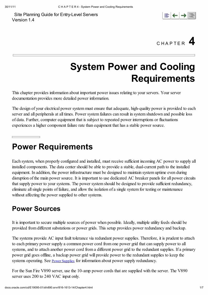
Site Planning Guide for Entry-Level ServersVersion 1.4
C H A P T E R 4
System Power and CoolingRequirements
This chapter provides information about important power issues relating to your servers. Your serverdocumentation provides more detailed power information.
The design of your electrical power system must ensure that adequate, high-quality power is provided to each
server and all peripherals at all times. Power system failures can result in system shutdown and possible lossof data. Further, computer equipment that is subject to repeated power interruptions or fluctuationsexperiences a higher component failure rate than equipment that has a stable power source.
Power Requirements
Each system, when properly configured and installed, must receive sufficient incoming AC power to supply all
installed components. The data center should be able to provide a stable, dual-current path to the installed
equipment. In addition, the power infrastructure must be designed to maintain system uptime even during
disruption of the main power source. It is important to use dedicated AC breaker panels for all power circuits
that supply power to your systems. The power system should be designed to provide sufficient redundancy,
eliminate all single points of failure, and allow the isolation of a single system for testing or maintenance
without affecting the power supplied to other systems.
Power Sources
It is important to secure multiple sources of power when possible. Ideally, multiple utility feeds should be
provided from different substations or power grids. This setup provides power redundancy and backup.
The systems provide AC input fault tolerance via redundant power supplies. Therefore, it is prudent to attach
to each primary power supply a common power cord from one power grid that can supply power to all
systems, and to attach another power cord from a different power grid to the redundant supplies. If a primary
power grid goes offline, a backup power grid will provide power to the redundant supplies to keep the
systems operating. See Power Supplies for information about power supply redundancy.
For the Sun Fire V890 server, use the 10-amp power cords that are supplied with the server. The V890
server uses 200 to 240 VAC input only.
30/11/11 C H A P T E R 4 - System Power and Cooling Requirements
2/7docs.oracle.com/cd/E19095-01/sfv890.srvr/816-1613-14/Chapter4.html
UPS and Backup Generator
Using an online uninterruptible power supply (UPS) and a backup power generator provides a good strategy
for obtaining an uninterruptible source of power. The online UPS filters, conditions, and regulates the power.It protects the systems from fluctuating voltages, surges and spikes, and noise that may be on the power line.
The battery backup for the UPS should be capable of maintaining the critical load of the data center for a
minimum of 15 minutes during a power failure. This is typically sufficient time to transfer power to an alternate
feed or to the power generator.
The backup power generator should be able to carry the load of both the computer equipment and the
supporting heat, ventilation, and air conditioning (HVAC) equipment. The generator should include dual
power distribution switch gear with automatic transfer switching. To offset the possibility of a generator
failure, power system designers often include a temporary generator for secondary backup.
Grounding
Grounding design must address both the electrical service and the installed equipment. A properly designed
grounding system should have as low an impedance as is practically achievable for proper operation ofelectronic devices as well as for safety. It is important to use a continuous, dedicated ground for the entire
power system to avoid a ground differential between various grounds. Grounding design in the United Statesshould comply with Article 250 of the U.S. National Electrical Code unless superseded by local codes. Use
an antistatic wrist strap when working inside the chassis.
All properly installed Sun systems are grounded through the power cable. However, there are reasons forinstalling an additional mechanism to equalize potential. Problematic or deficient conduits can negatively affectanother system, especially with respect to the possibility of spreading voltages. Additional grounding points
help to avoid leakage current, which prevent system malfunctions. Therefore, additional cables might be usedto connect Sun systems and cabinets to the data center's potential equalization rail. Enlist the aid of a qualified
electrician to install grounding cables.
Emergency Power Control
A primary power switch that can disconnect all electronic equipment in the data center is specified by NFPA
70 and NFPA 75 (National Fire Protection Association specifications) at each point of entry to the datacenter. The primary switch should disconnect power to all computer systems and related electronic
equipment, HVAC equipment, UPS, and batteries. Multiple disconnects for separate parts of the powersystems are also acceptable, but in both cases, the switches must be unobstructed and clearly marked.
Power Constraints
All servers covered by this guide are shipped with a sufficient number of power supplies to provide all power
needed by all Sun supported configurations.
Sun does not test many third-party products that are compatible with Sun servers. Therefore, Sun makes no
30/11/11 C H A P T E R 4 - System Power and Cooling Requirements
3/7docs.oracle.com/cd/E19095-01/sfv890.srvr/816-1613-14/Chapter4.html
representations about those products or about the power requirements for products not supplied by Sun.
Power constraints can occur in two areas:
Total AC power consumption
Current limit of the AC power outlet
To maintain a safe facility, you must ensure that the AC current draw does not exceed the maximum current
limit for your power outlet. In the United States and Canada, the maximum is 80% of the outlet's totalcapacity, which is 12 amps for 15-amp circuits and 16 amps for 20-amp circuits, and so forth. For areas outside of the United States and
Canada, contact local agencies for information about local electrical codes.
See TABLE 5-4 for maximum input current and power consumption for the servers.
Power Supplies
Each server covered by this guide is shipped by Sun with one or more power supplies, which are sufficient to
support the maximum configuration of the server.
The systems provide "N+1" power supply redundancy to maintain system uptime. An N+1 redundant powersupply configuration does not add to the power capacity of the systems. "N" represents the number of power
supplies needed to power a fully configured system. The "1" means that there is one additional power supplyin the system to handle the load if a supply fails. When the system is operating normally, all of the power
supplies are turned on, even the redundant supplies.
The redundancy configurations of the systems are as follows:
1+1, One supply needed to power the system and one backup supply
250 server
280R server
V480 server
V440 server
2+1, Two supplies needed to power the system and one backup supply
V880 server
V890 server
In a 1+1 configuration (that is, two power supplies are installed, each capable of providing enough power for
the entire system), both supplies are turned on and are delivering power. Each supply delivers approximately
50% of the power needed by the system. If one supply fails, the supply that is still online will deliver 100% of
the power needed to keep the system running.
30/11/11 C H A P T E R 4 - System Power and Cooling Requirements
4/7docs.oracle.com/cd/E19095-01/sfv890.srvr/816-1613-14/Chapter4.html
In a 2+1 configuration (that is, three power supplies are installed, with two power supplies delivering enough
power for the entire system), all three power supplies are turned on and are delivering power. Each supply
delivers approximately 33% of the power needed by the system. If one supply fails, the supplies that are stillonline will each provide 50% of the power needed to keep the system running.
Most power supplies cannot support the maximum values on all outputs at the same time because that would
exceed the total power supply output capacity. The load must be distributed among the outputs in a way thatdoes not exceed their maximum values or the total output capacity of the power supply.
The servers have built-in protection against exceeding the output capacity of the power supply configuration.Be sure to consult the server documentation to learn how the servers will react during a power overload.
PCI Bus Power
The PCI slots in the Sun servers comply with PCI Local Bus Specification Revision 2.1. The PCI bus in eachserver is designed to provide 15 watts of power multiplied by the number of PCI slots in the PCI chassis.
Thus, a four-slot PCI chassis has a total of 60 watts of power available. These 60 watts can be used in any
manner that conforms to the PCI standard. A single PCI slot can support a card that requires up to 25 watts.
Here are some examples of how you might populate a four-slot PCI chassis:
Example 1 - You install four 15-watt cards. These four 15-watt cards would use up all of the 60
watts of available power in the PCI chassis. They would also occupy all four of the available PCI slots.
Example 2 - You install two 22-watt cards plus one 15-watt card. This combination of cards would
use 59 watts of the 60 watts available. In all probability, you would have to leave the fourth slot empty
in this example, unless you could find a PCI card that required only 1 watt.
Heat Output and Cooling
Servers and related equipment generate a considerable amount of heat in a relatively small area. This is
because every watt of power used by a system is dissipated into the air as heat. The amount of heat output
per server varies, depending on the system configuration. See TABLE 5-4 for heat output measurements for theservers.
The heat load in a data center is seldom distributed uniformly and the areas generating the most heat canchange frequently. Further, data centers are full of equipment that is highly sensitive to temperature and
humidity fluctuations. See TABLE 5-5 for the servers' temperature and humidity specifications.
Proper cooling and related ventilation of a server within a cabinet is affected by many variables, including thecabinet and door construction, cabinet size, and thermal dissipation of any other components within the
cabinet. Therefore, it is the responsibility of the data center manager to ensure that the cabinet's ventilation
system is sufficient for all the equipment mounted in the cabinet.
Do not use the servers' nameplate power ratings when calculating the servers' heat release. The purpose of
the nameplate power ratings is solely to indicate the servers' hardware limits for maximum power draw.
30/11/11 C H A P T E R 4 - System Power and Cooling Requirements
5/7docs.oracle.com/cd/E19095-01/sfv890.srvr/816-1613-14/Chapter4.html
Chassis Airflow
The flow of air through the servers is essential to the proper cooling of the servers. Even though the data
center air may be at a safe and steady temperature at one location, the temperature of the air entering eachserver is critical. Problems sometimes arise for these reasons:
One server is positioned so that its hot exhaust air is directed into the intake air of another server, thus
preheating the intake air of the second server.
Servers are sometimes mounted in cabinets that restrict airflow excessively. This might occur because
the cabinets have solid front or rear doors, inadequate plenums, or they might have cooling fans that
work against the fans in the servers themselves.
A server might be mounted in a cabinet above a device that generates a great amount of heat.
All of the servers described in this guide draw in ambient air for cooling from the front and discharge heatedexhaust air to the rear. The servers require that the front and back cabinet doors to be at least 63% open for
adequate airflow. This can be accomplished by removing the doors, or by ensuring that the doors have a
perforated pattern that provides at least 63% open area. In addition, maintain a minimum of 1.5-inch (3.8-
cm) clearance between the systems and front and back doors of a cabinet.
The servers are equipped with fans that route cool air throughout the chassis. As long as the necessary air
conditioning is provided in the data center to dissipate the heat load, and sufficient space and door openingsare provided at the front and back of the servers, the fans will enable the rackmounted servers to work within
the temperature specifications for systems in operation. See TABLE 5-5 for temperature specifications. See
Cabinet Location for information about recommended placement of cabinets and racks to optimize proper aisle
airflow.
Units of Measurement
A standard unit for measuring the heat generated within, or removed from, a data center is the British Thermal
Unit (Btu). The heat produced by electronic devices such as servers is usually expressed as the number of
Btu generated in an hour (Btu/hr).
Watts (W) is also a term used to express heat output and cooling. One watt is equal to 3.412 Btu/hr. For
example, if you use 100 watts of power, you generate
341.2 Btu/hr.
Air conditioning capacity is also measured in Btu/hr or watts. Large air conditioning systems are rated in tons.
One ton of air conditioning is a unit of cooling equal to 12,000 Btu/hr or 3517 watts.
Determining Heat Output and Cooling
TABLE 5-4 lists the minimum, typical, and maximum heat output and cooling requirements for baseconfigurations of the servers. These specification are the measured power ratings, which are calculated for
the base server configurations as defined by Sun and listed in TABLE 5-3. Use the nameplate ratings only as a
references to the servers' hardware limits that could accommodate future components and not to calculate the
30/11/11 C H A P T E R 4 - System Power and Cooling Requirements
6/7docs.oracle.com/cd/E19095-01/sfv890.srvr/816-1613-14/Chapter4.html
servers' current power and cooling requirements.
In addition to the heat load generated by the servers, some cabinets include fans, power sequencers, and
other devices that generate heat. Be sure to obtain the heat output values of these devices from your cabinetsupplier. Also, when calculating data center cooling requirements, be sure to include heat dissipation for all
equipment in the room.
To determine the heat output and cooling requirements of the rackmounted servers, add the Btu or watts for
each server in the rack. For example, if one server is putting out 1000 Btu/hr (293 watts) and another one is
putting out 2000 Btu/hr (586 watts), the total heat generated is 3000 Btu/hr (879 watts). The air conditioning
equipment then should be properly sized to cool at least 3000 Btu/hr (879 watts) to accommodate these two
systems.
If you only have wattage measurements and want to obtain the equivalent Btu rating, multiply the total wattage
by 3.41 to obtain the Btu/hr. To calculate tons of air conditioning, multiply the total wattage by 0.000285.
See Calculating Cooling Requirements for an example of how to estimate cooling requirements based on the
square footage used by the cabinets and racks in the data center.
Using Rack Location Units to Determine Heat Output andCooling
In the book Enterprise Data Center Design and Methodology by Rob Snevely (available at
h t t p : / / w w w . s u n . c o m / b o o k s / b l u e p r i n t s . s e r i e s . h t m l ) the concept of using rack
location units (RLUs) to determine heat output and cooling requirements in the data center is discussed. A
rack location is the specific location on the data center floor where services that can accommodate power,
cooling, physical space, network connectivity, functional capacity, and rack weight requirements aredelivered. Services delivered to the rack location are specified in units of measure, such as watts or Btus, thus
forming the term rack location unit.
Since today's data centers house hundreds or thousands of systems with widely varying power and cooling
requirements, RLUs can help you determine where greater or less power and cooling services are needed.
RLUs can also help you determince how to locate the racks to maximize services. Using square footage
calculations for power and cooling assumes that power and cooling loads are the same across the entireroom. Using RLUs lets you divide the data center into areas that need unique power and cooling services.
To determine RLUs for heat output and cooling, you must add together the heat output and cooling
requirements for all systems installed in the rack. Then assess the RLUs for adjacent racks. For example,
suppose you had 24,000 square feet of space in the data center. You might have a 12,000-square foot area
where 600 PCs are outputing 552,000 Btu/hour and needing 46 Btu/hour of cooling per square foot. Another
6000-square foot area might contain 48 severs outputting 1,320,000 Btu/hour and needing 220 Btu/hour of
cooling per square foot. A third 6000-square foot area might contain 12 high-end servers outputting 972,000Btu/hour and needing 162 Btu/hour of cooling per square foot.
Using a square footage calculation for this example yields a cooling requirement for all three sections of
2,844,000 Btu/hour, or 118.5 Btu/hour of cooling per square foot. This would exceed the 46 Btu/hour
cooling needed by the PCs, but it is much too little cooling capacity required for both server areas. Knowing
the RLUs for power and cooling enable the data center manager to adjust the physical design, the power and
cooling equipment, and rack configurations within the facility to meet the systems' requirements.
30/11/11 C H A P T E R 4 - System Power and Cooling Requirements
7/7docs.oracle.com/cd/E19095-01/sfv890.srvr/816-1613-14/Chapter4.html
Site Planning Guide for Entry-LevelServers Version 1.4
816-1613-14
Copyright © 2004, Sun Microsystems, Inc. All rights reserved.