Embed Size (px)
Citation preview
C. KesselPrinceton Plasma Physics Laboratory
For the NSTX National Team
DOE Review ofNSTX Five-Year Research Program Proposal
June 30 – July 2, 2003
Integrated Scenario Modeling
Supported by
Columbia UComp-X
General AtomicsINEL
Johns Hopkins ULANLLLNL
LodestarMIT
Nova PhotonicsNYU
ORNLPPPL
PSISNL
UC DavisUC Irvine
UCLAUCSD
U MarylandU New Mexico
U RochesterU Washington
U WisconsinCulham Sci Ctr
Hiroshima UHIST
Kyushu Tokai UNiigata U
Tsukuba UU TokyoIoffe Inst
TRINITIKBSI
KAISTENEA, Frascati
CEA, CadaracheIPP, Jülich
IPP, GarchingU Quebec
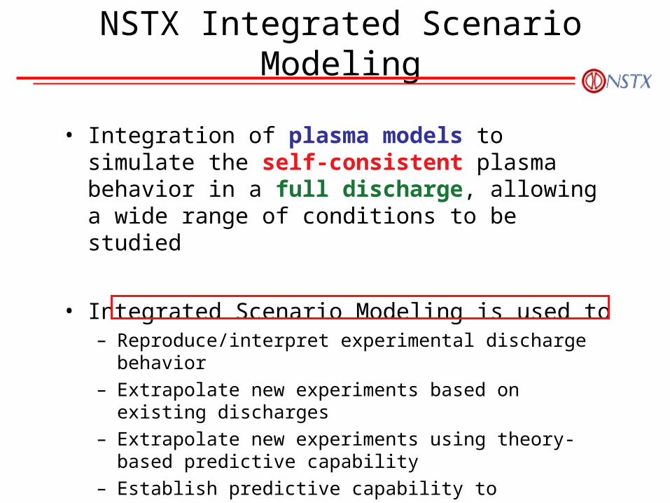
NSTX Integrated Scenario Modeling
• Integration of plasma models to simulate the self-consistent plasma behavior in a full discharge, allowing a wide range of conditions to be studied
• Integrated Scenario Modeling is used to– Reproduce/interpret experimental discharge behavior– Extrapolate new experiments based on existing discharges– Extrapolate new experiments using theory-based predictive
capability– Establish predictive capability to extrapolate to new devices,
such as NSST (Next Step ST) and CTF (Component Test Facility)
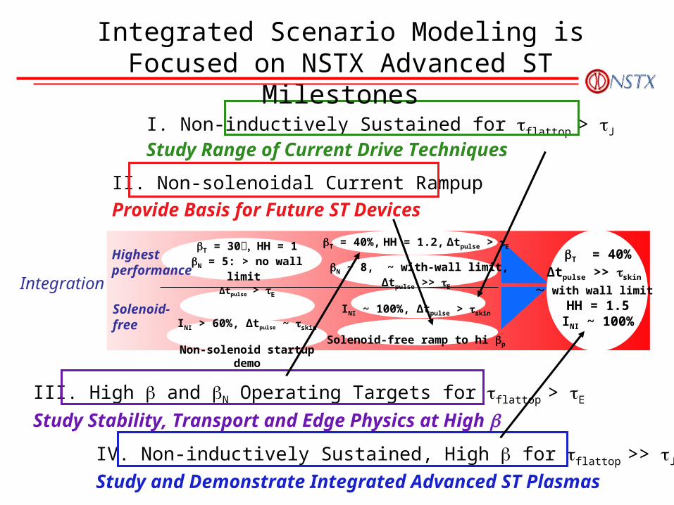
IV. Non-inductively Sustained, High for flattop >> J
Study and Demonstrate Integrated Advanced ST Plasmas
III. High and N Operating Targets for flattop > E
Study Stability, Transport and Edge Physics at High
II. Non-solenoidal Current Rampup
Provide Basis for Future ST Devices
I. Non-inductively Sustained for flattop > J
Study Range of Current Drive Techniques
Integrated Scenario Modeling is Focused on NSTX Advanced ST Milestones
Integration
Solenoid- free
T = 30 HH = 1N = 5: > no wall limit
∆tpulse > E
INI > 60%, ∆tpulse ~ skin
Non-solenoid startup demo
Highest performance
T = 40%∆tpulse >> skin
with wall limit HH = 1.5
INI ~ 100%
T = 40%, HH = 1.2, ∆tpulse > E
N ~ 8, ~ with-wall limit,∆tpulse >> E
INI ~ 100%, ∆tpulse > skin
Solenoid-free ramp to hi p
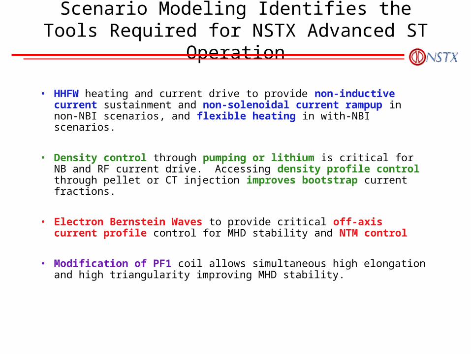
Scenario Modeling Identifies the Tools Required for NSTX Advanced ST Operation
• HHFW heating and current drive to provide non-inductive current sustainment and non-solenoidal current rampup in non-NBI scenarios, and flexible heating in with-NBI scenarios.
• Density control through pumping or lithium is critical for NB and RF current drive. Accessing density profile control through pellet or CT injection improves bootstrap current fractions.
• Electron Bernstein Waves to provide critical off-axis current profile control for MHD stability and NTM control
• Modification of PF1 coil allows simultaneous high elongation and high triangularity improving MHD stability.
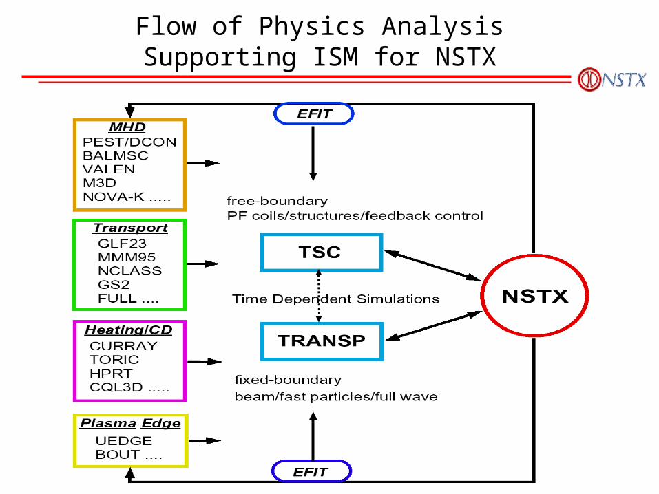
Flow of Physics Analysis Supporting ISM for NSTX
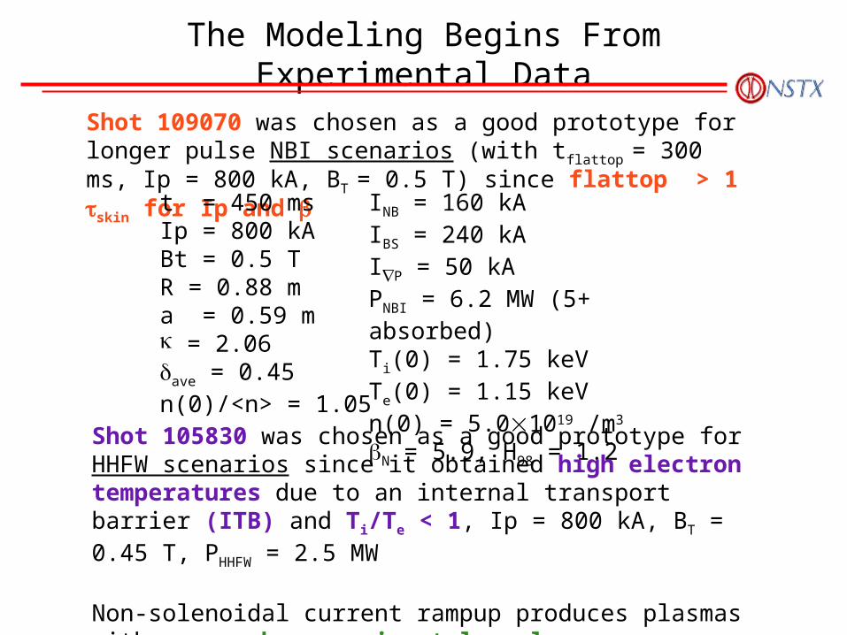
The Modeling Begins From Experimental Data
Shot 109070 was chosen as a good prototype for longer pulse NBI scenarios (with tflattop = 300 ms, Ip = 800 kA, BT = 0.5 T) since flattop > 1 skin for Ip and
t = 450 msIp = 800 kABt = 0.5 TR = 0.88 ma = 0.59 m = 2.06ave = 0.45n(0)/<n> = 1.05
INB = 160 kAIBS = 240 kAIP = 50 kAPNBI = 6.2 MW (5+ absorbed)Ti(0) = 1.75 keVTe(0) = 1.15 keVn(0) = 5.01019 /m3
N = 5.9, H98 = 1.2Shot 105830 was chosen as a good prototype for HHFW scenarios since it obtained high electron temperatures due to an internal transport barrier (ITB) and Ti/Te < 1, Ip = 800 kA, BT = 0.45 T, PHHFW = 2.5 MW
Non-solenoidal current rampup produces plasmas with no nearby experimental analog
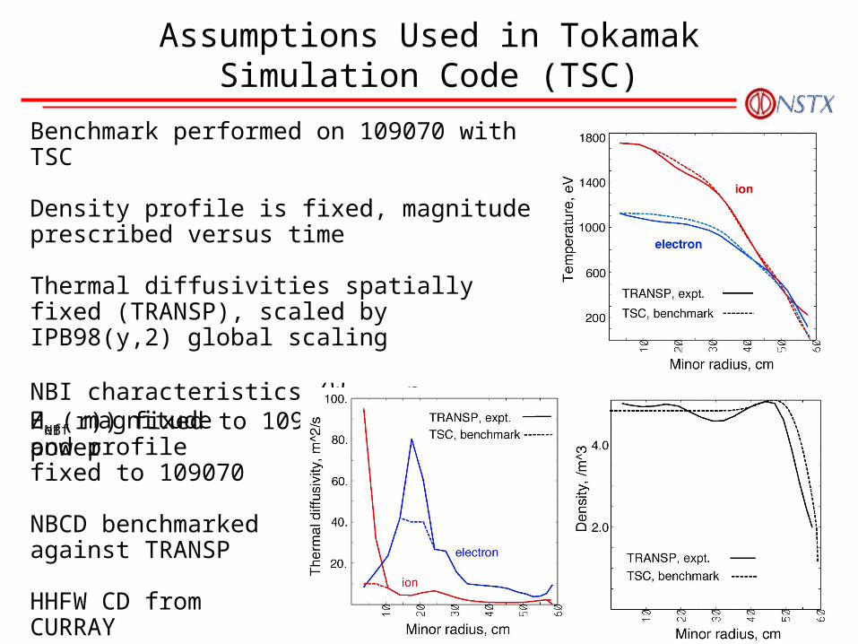
Assumptions Used in Tokamak Simulation Code (TSC)
Benchmark performed on 109070 with TSC
Density profile is fixed, magnitude prescribed versus time
Thermal diffusivities spatially fixed (TRANSP), scaled by IPB98(y,2) global scaling
NBI characteristics (Wbeam, nfast, HNB(r)) fixed to 109070, scaled by power
Zeff magnitude and profile fixed to 109070
NBCD benchmarked against TRANSP
HHFW CD from CURRAY
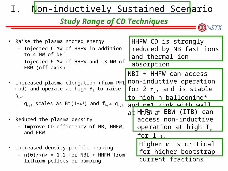
• Raise the plasma stored energy
– Injected 6 MW of HHFW in addition to 4 MW of NBI
– Injected 6 MW of HHFW and 3 MW of EBW (off-axis)
• Increased plasma elongation (from PF1 mod) and operate at high BT to raise qcyl
– qcyl scales as Bt(1+2) and fbs qcyl
• Reduced the plasma density
– Improve CD efficiency of NB, HHFW, and EBW
• Increased density profile peaking
– n(0)/<n> = 1.1 for NBI + HHFW from lithium pellets or pumping
HHFW CD is strongly reduced by NB fast ions and thermal ion absorption
NBI + HHFW can access non-inductive operation for 2 J, and is stable to high-n ballooning* and n=1 kink with wall at 1.5 a
HHFW + EBW (ITB) can access non-inductive operation at high Te for 1 J
Higher is critical for higher bootstrap current fractions
I. Non-inductively Sustained ScenarioStudy Range of CD Techniques
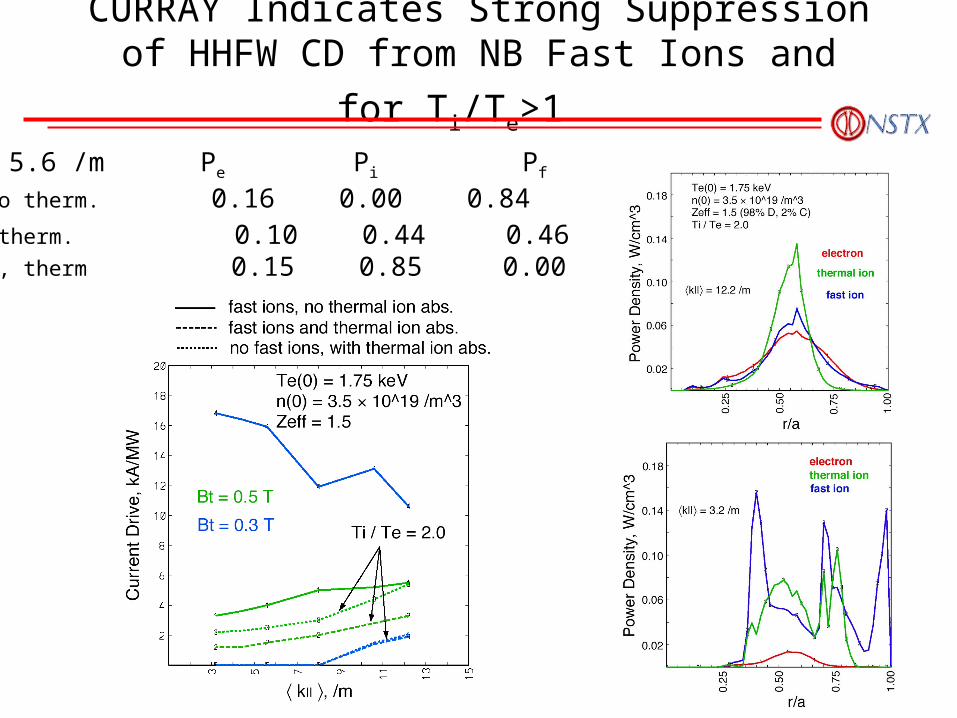
CURRAY Indicates Strong Suppression of
HHFW CD from NB Fast Ions and for Ti/Te>1
k|| = 5.6 /m Pe Pi Pf
Fast, no therm. 0.16 0.00 0.84Fast + therm. 0.10 0.44 0.46No fast, therm 0.15 0.85 0.00
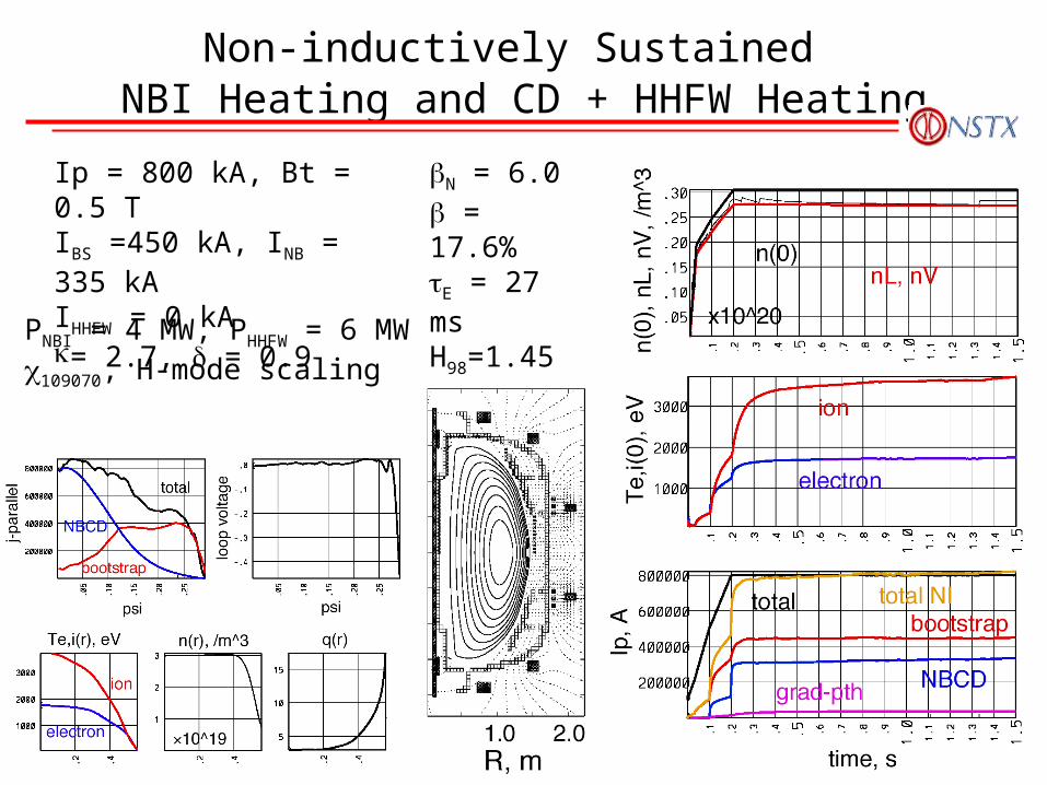
Non-inductively Sustained NBI Heating and CD + HHFW Heating
Ip = 800 kA, Bt = 0.5 TIBS =450 kA, INB = 335 kAIHHFW = 0 kA= 2.7, = 0.9
N = 6.0 = 17.6%E = 27 ms H98=1.45qcyl = 4.0li(1) = 0.5
PNBI = 4 MW, PHHFW = 6 MW109070, H-mode scaling
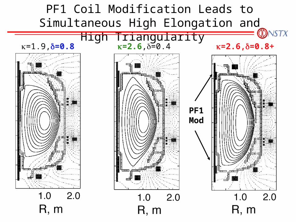
=2.6,=0.8+=2.6,=0.4=1.9,=0.8
PF1Mod
PF1 Coil Modification Leads to Simultaneous High Elongation and High Triangularity
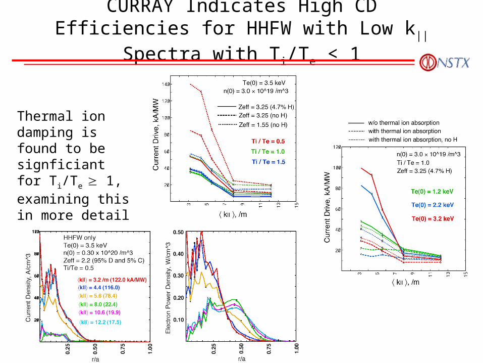
CURRAY Indicates High CD Efficiencies for HHFW with Low k|| Spectra with Ti/Te < 1
Thermal ion damping is found to be signficiant for Ti/Te 1, examining this in more detail
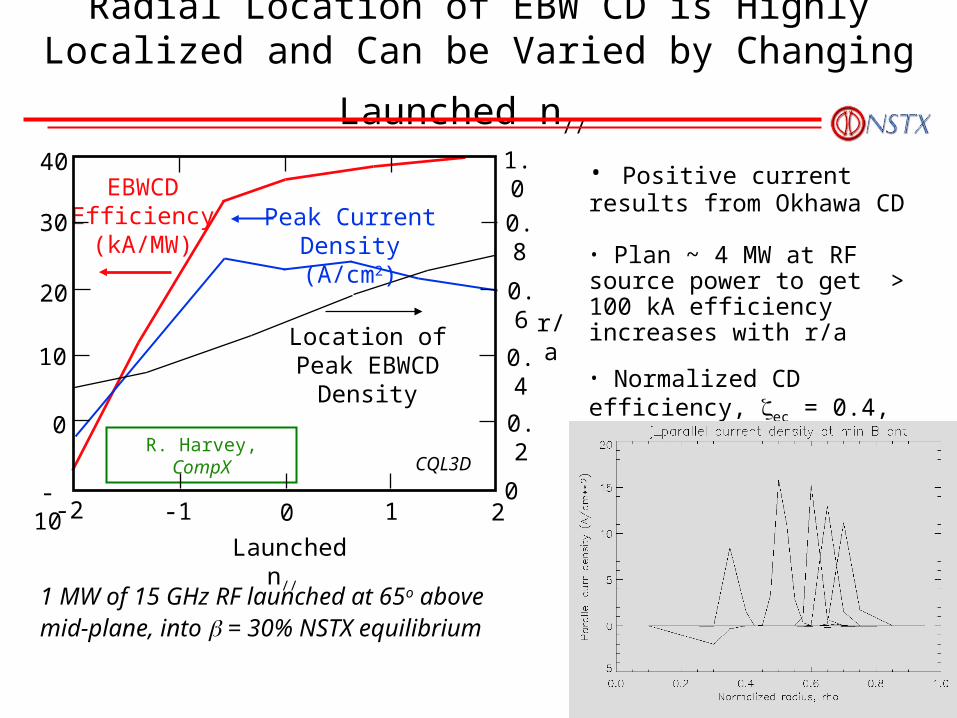
Radial Location of EBW CD is Highly Localized and
Can be Varied by Changing Launched n//
1 MW of 15 GHz RF launched at 65o above mid-plane, into = 30% NSTX equilibrium
CQL3DR. Harvey, CompX
• Positive current results from Okhawa CD • Plan ~ 4 MW at RF source power to get > 100 kA efficiency increases with r/a • Normalized CD efficiency, ec = 0.4, compares favorably to ECCD
EBWCDEfficiency(kA/MW)
Peak CurrentDensity (A/cm2)
Location ofPeak EBWCD
Density
1.0
0
0.2
0.4
0.6
0.8
r/a
0 1 2-1-2
Launched n//
0
10
20
30
40
-10
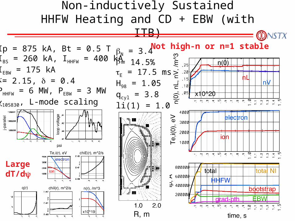
Non-inductively SustainedHHFW Heating and CD + EBW (with ITB)
Ip = 875 kA, Bt = 0.5 TIBS = 260 kA, IHHFW = 400 kAIEBW = 175 kA= 2.15, = 0.4PHHFW = 6 MW, PEBW = 3 MW105830, L-mode scaling
N = 3.4= 14.5%E = 17.5 msH98 = 1.05qcyl = 3.8li(1) = 1.0
Not high-n or n=1 stable
Large dT/d
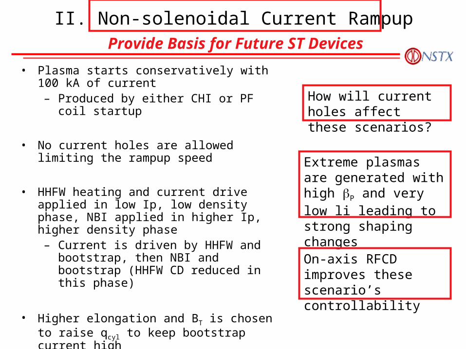
• Plasma starts conservatively with 100 kA of current– Produced by either CHI or PF coil startup
• No current holes are allowed limiting the rampup speed
• HHFW heating and current drive applied in low Ip, low density phase, NBI applied in higher Ip, higher density phase– Current is driven by HHFW and bootstrap,
then NBI and bootstrap (HHFW CD reduced in this phase)
• Higher elongation and BT is chosen to raise qcyl to keep bootstrap current high
• PF coils assist the current rampup while they provide equilibrium field
Extreme plasmas are generated with high P and very low li leading to strong shaping changes
On-axis RFCD improves these scenario’s controllability
How will current holes affect these scenarios?
II. Non-solenoidal Current RampupProvide Basis for Future ST Devices
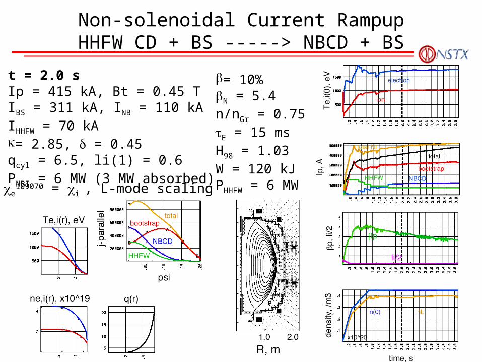
Non-solenoidal Current RampupHHFW CD + BS -----> NBCD + BS
t = 2.0 sIp = 415 kA, Bt = 0.45 TIBS = 311 kA, INB = 110 kAIHHFW = 70 kA= 2.85, = 0.45qcyl = 6.5, li(1) = 0.6PNBI = 6 MW (3 MW absorbed)
= 10%N = 5.4n/nGr = 0.75E = 15 msH98 = 1.03W = 120 kJPHHFW = 6 MWe
109070 = i , L-mode scaling
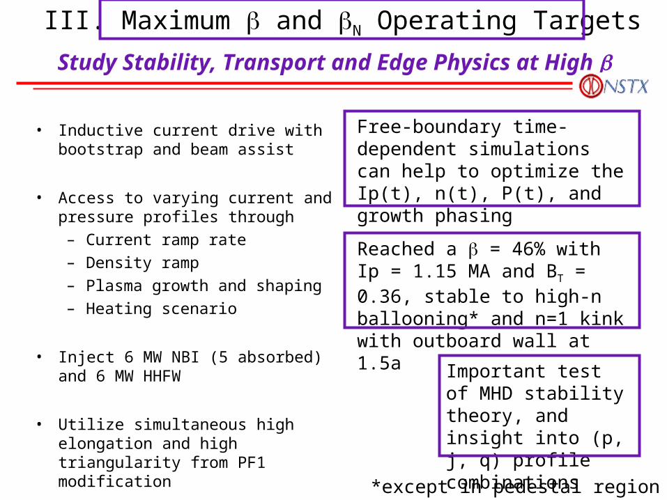
• Inductive current drive with bootstrap and beam assist
• Access to varying current and pressure profiles through
– Current ramp rate
– Density ramp
– Plasma growth and shaping
– Heating scenario
• Inject 6 MW NBI (5 absorbed) and 6 MW HHFW
• Utilize simultaneous high elongation and high triangularity from PF1 modification
Reached a = 46% with Ip = 1.15 MA and BT = 0.36, stable to high-n ballooning* and n=1 kink with outboard wall at 1.5a
Important test of MHD stability theory, and insight into (p, j, q) profile combinations
Free-boundary time-dependent simulations can help to optimize the Ip(t), n(t), P(t), and growth phasing
*except in pedestal region
III. Maximum and N Operating Targets
Study Stability, Transport and Edge Physics at High
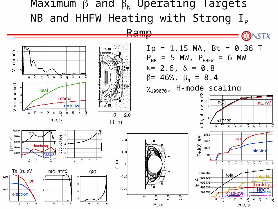
Maximum and N Operating TargetsNB and HHFW Heating with Strong IP Ramp
Ip = 1.15 MA, Bt = 0.36 TPNB = 5 MW, PHHFW = 6 MW= 2.6, = 0.8= 46%, N = 8.4109070, H-mode scaling
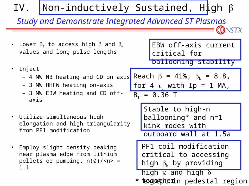
• Lower BT to access high and N values and long pulse lengths
• Inject
– 4 MW NB heating and CD on axis
– 3 MW HHFW heating on-axis
– 3 MW EBW heating and CD off-axis
• Utilize simultaneous high elongation and high triangularity from PF1 modification
• Employ slight density peaking near plasma edge from lithium pellets or pumping, n(0)/<n> = 1.1
Reach = 41%, N = 8.8, for 4 J with Ip = 1 MA, BT = 0.36 T
EBW off-axis current critical for ballooning stability
PF1 coil modification critical to accessing high N by providing high and high together
Stable to high-n ballooning* and n=1 kink modes with outboard wall at 1.5a
* except in pedestal region
IV. Non-inductively Sustained, High Study and Demonstrate Integrated Advanced ST Plasmas
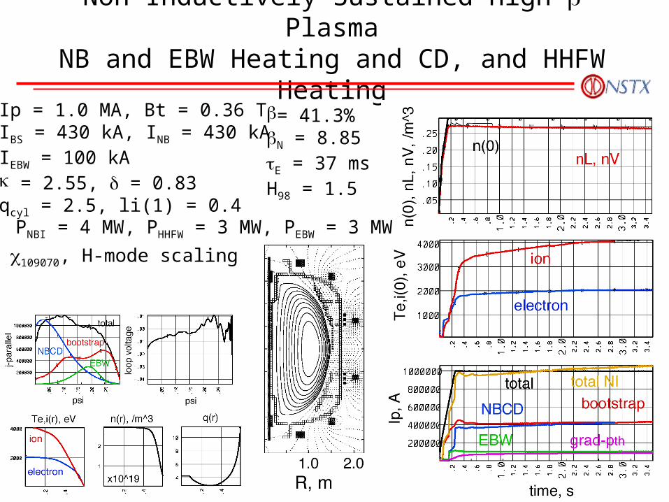
Non-Inductively Sustained High PlasmaNB and EBW Heating and CD, and HHFW Heating
Ip = 1.0 MA, Bt = 0.36 TIBS = 430 kA, INB = 430 kAIEBW = 100 kA = 2.55, = 0.83qcyl = 2.5, li(1) = 0.4
= 41.3%N = 8.85E = 37 msH98 = 1.5
PNBI = 4 MW, PHHFW = 3 MW, PEBW = 3 MW
109070, H-mode scaling
Further Investigations and Development for Integrated Scenario Modeling
• HHFW CD efficiency– Fast ion absorption– Thermal ion absorption– Install ray-tracing in
transport codes– Expand scans of plasma
parameter dependences especially at high
• EBW CD– Improve modeling and
parameter dependences
• NBI analysis– Low Ip scenarios– Integrate TSC free-
boundary features with advanced source models in TRANSP
• Plasma transport– Continue to rely on expt. ’s
as discharges move closer to scenarios
– Use NSTX specific global scaling
– Pursue a GLF23-Low A predictive transport model
• MHD stability– Detailed conductor
geometry– High plasma rotation
speeds– Impact of higher n modes– RWM feedback stabilization– NTM’s – FLR and flow effects on
ballooning modes
NSTX is Using Integrated Scenario Modeling to Plan Future Experiments
• Advanced ST plasmas have been identified– Non-inductively Sustained for flattop > J, to study HHFW, EBW, and NB
CD techniques– Non-solenoidal current rampup, to examine the feasibility for future ST
devices– High and N Operating Targets, to study stability, transport and edge
physics in high – Non-inductively Sustained, High for flattop >> J, to study integrated
Advanced ST plasmas
• Identifying the critical tools to access Advanced ST plasmas– HHFW heating and CD on/near-axis– EBW CD off-axis– Strong plasma shaping through PF coil modifications– Density control
• Continuing to expand the capability of integrated modeling to better project behavior of future experiments and devices
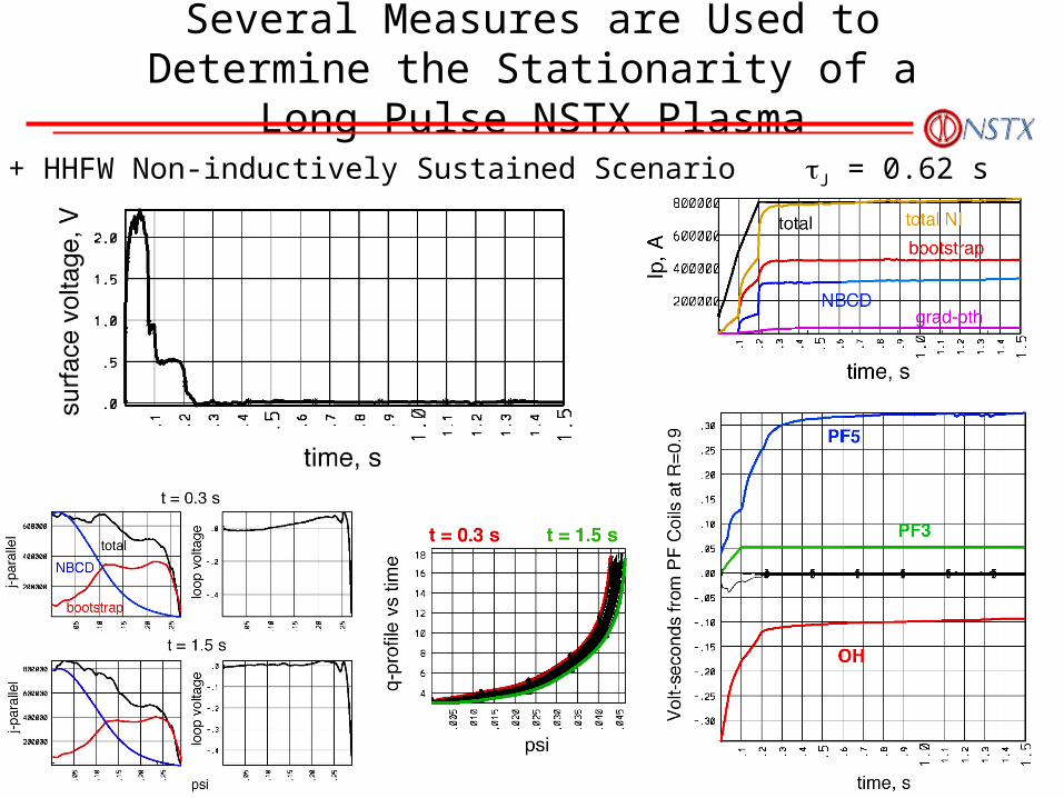
Several Measures are Used to Determine the Stationarity of a Long Pulse NSTX Plasma
NBI + HHFW Non-inductively Sustained Scenario J = 0.62 s
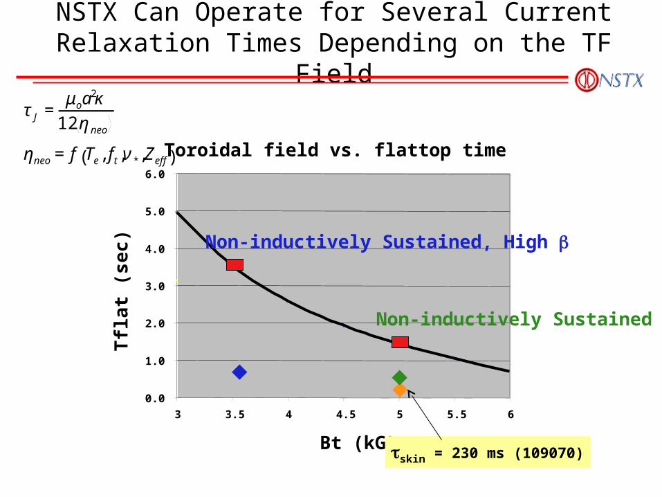
NSTX Can Operate for Several Current Relaxation Times Depending on the TF Field
Toroidal field vs. flattop time
0.0
1.0
2.0
3.0
4.0
5.0
6.0
3 3.5 4 4.5 5 5.5 6
Bt (kG)
Tfl
at
(sec)
skin = 230 ms (109070)
Non-inductively Sustained, High
Non-inductively Sustained
€
τJ =μoa
2κ12ηneo
ηneo=f Te, ft,ν*,Zeff( )