Embed Size (px)
Citation preview
ofc_Layout 2 1/7/14 2:08 PM Page 1

INTERNATIONAL CUSTOMERSDwyer has local distributors in over 50 countries. Contact the office of your country or contact the corporate headquarters
to find your local distributor. You can also go to our website at the following address to be contacted by your local
distributor: http://www.dwyer-inst.com/Distributors/DistContactInfo.cfm.
PHONEDWYER INSTRUMENTS, INC.
800/872-9141219/879-8000
PROXIMITY CONTROLS
800/346-9819218/739-3364
FAXDWYER INSTRUMENTS, INC.
219/872-9057
PROXIMITY CONTROLS
218/739-2734
WEBSITEwww.ProximityControls.com
Corporate Headquarters
DWYER INSTRUMENTS, INC.102 Indiana Highway 212,
P.O. Box 373
Michigan City, IN 46360, U.S.A.
PHONE FAX
219/879-8000 219/872-9057
United Kingdom
DWYER INSTRUMENTS LTDUnit 16, The Wye Estate, London Road
High Wycombe, Bucks HP11 1LH-U.K.
PHONE FAX
(+44) (0) 1494 461707 (+44) (0) 1494 465102
Australia
DWYER INSTRUMENTS, PTY. LTD.Unit 1, 11 Waverley Drive
Unanderra, NSW 2526 Australia
PHONE FAX(+61) (0) 2 4272 2055 (+61) (0) 2 4272 4055
Hong Kong
DWYER INSTRUMENTS HK, LTD.Unit 605A, 6/F, Shui Hing Centre
13 Sheung Yuet Road, Kowloon Bay, Hong Kong
PHONE FAX+852-23181007 +852-27561565
ORDERING
IS EASY FROM DWYER
LOCAL SUPPORT GLOBALLY
DWYER AROUND THE GLOBE
TECHNICAL SUPPORT, LITERATURE REQUESTS,QUOTATIONS AND GENERAL INFORMATION
ifc_Layout 2 1/7/14 2:07 PM Page 1

1Phone: 218/739-3364 • 219/879-8000 | Fax: 218/739-2734 • 219/872-9057
Proximity ControlsA DIVISIoN oF Dwyer INSTrUMeNTS, INC.
1431 STATe HIgHwAy 210e
FergUS FALLS, MN 56537
Phone: 800/346-9819 • 218/739-3364
fax: 218/739-2734
www.ProximityControls.Com
Proximity Controls was started in 1965 out of a garage in Fergus Falls, MN. The first product line was the Ultra-MagTM Series of
diaphragm level controls. The Ultra-MagTM offers a unique and patented magnetic drive that seals the switch compartment.
Building on their experience with magnetic drives, Proximity expanded into position indicators in 1977 with the invention of the
Mark Series. Like the Ultra-MagTM, the Mark Series offers a patented magnetic drive that completely seals the switch
compartment.
Proximity Controls was acquired in 1989 by Dwyer Instruments of Michigan City, IN. Proximity Controls is still operated out of
Fergus Falls today. Dwyer continues the innovative spirit of Proximity Controls by continually developing new products such as
the Quick-View® and DetectorTM position indicating controls and the PLS rotating paddle level switch.
This catalog only includes the Proximity Controls position indicating product line. For Proximity Controls level products, please
go to the Dwyer Instruments, Inc. website at www.dwyer-inst.com.
INTRODUCTION
001_Layout 2 1/7/14 12:57 PM Page 1

PROXIMITY CONTROLS, A Division of Dwyer Instruments, Inc. | 1431 State Hwy 210 E, Fergus Falls, MN 565372
All of our technical sales staff are degreed engineers trained to be product and
industry experts. We listen to your needs and get you the answers you want
quickly.
WE HELP YOU FIND A SOLUTION
TO CONTACT A TECHNICAL SUPPORT ENGINEER
PHONE
218/739-3364
FAX
218/739-2734
REAL PEOPLE
Courteous and professional customer service representatives are available via
phone and email to process and provide assistance with your order. Dwyer
provides industry leading response time to answer your call quickly without
making you wait.
PRICING
Contact us for formal quotes, Dwyer offers bids and project quotes. Discounts
are available for particular customer types based on quantities purchased.
LARGE INVENTORY LOCATED CENTRALLY IN THE U.S.
Dwyer is committed to get you your order quickly with more than 5,000 line
items in stock in our Michigan City, Indiana headquarters and in most cases
lead times less than two weeks for non-stock products.
FAST PROCESSING AND PACKING
Our dedicated shipping staff packs and ships your order the same day on stock
items ordered before 2:00 PM U.S. Central Time.
FLEXIBLE SHIPPING
Dwyer offers blanket orders for OEM’s to schedule out your product shipments
to be when you need them. Contact us for details.
• Product Selection
• Application Assistance
• Regulatory and Agency Approval
Compliance
• Installation Guidance
• Maintenance and Repair
• Product Customization for OEM’s
CUSTOMER SERVICE
PRODUCT DELIVERY
TECHNICAL SUPPORT
FRIENDLY AND FAST
PROMPT AND ACCURATE
KNOWLEDGEABLE AND HELPFUL
002_Layout 2 1/7/14 12:58 PM Page 1
3Phone: 218/739-3364 • 219/879-8000 | Fax: 218/739-2734 • 219/872-9057
Dwyer Instruments, Inc. - Standard Terms and Conditions of Sale
1. Prices and Specifications are subject to change without notice.
2. Shipping dates are approximate. They are dependent upon credit approval and subject to delays beyond our control.
3. Terms: Net 30 days to companies with established credit rating. In the event Buyer fails to fulfill previous terms of payment,or in case Seller shall have any doubt at any time as to Buyer’s financial responsibility, Seller may decline to make furtherdeliveries except upon receipt of cash in advance or other special arrangements.
4. Liability Point and Title: All material is sold EXW Ex Works Dwyer Instruments, Inc. Title to all material sold shall pass tobuyer upon delivery by Seller to carrier at shipping point.
5. State and Local Taxes: Any taxes which the Seller may be required to pay or collect upon or with respect to the sale,purchase, delivery, use or consumption of any of the material covered hereby shall be for the account of the Buyer and shall beadded to the purchase price.
6. Special tooling, dies, silk screens and molds acquired specially to produce goods for Buyer remain the property of DwyerInstruments, Inc., and may not be removed. They will be maintained in good condition for a minimum period of three years fromthe date of the original purchase order.
7. Export Orders: Terms, discounts and conditions of sale for purchase orders originating or for shipment to final destinationsoutside the U.S.A. will be furnished upon request.
8. Limited Warranty: The Seller warrants all Dwyer instruments and equipment to be free from defects in workmanship ormaterial under normal use and service for a period of one year from date of shipment. Liability under this warranty is limited torepair or replacement EXW Ex Works Dwyer Instruments, Inc of any parts which prove to be defective within that time orrepayment of the purchase price at the Seller’s option provided the instruments have been returned, transportation prepaid,within one year from date of purchase. All technical advice, recommendations and services are based on technical data andinformation which the Seller believes to be reliable and are intended for use by persons having skill and knowledge of thebusiness, at their own discretion. In no case is Seller liable beyond replacement of equipment EXW Ex Works Dwyer Instruments,Inc or the full purchase price. This warranty does not apply if the maximum ratings label is removed or if the instrument orequipment is abused, altered, used at ratings above the maximum specified, or otherwise misused in any way.
THIS EXPRESS LIMITED WARRANTY IS IN LIEU OF AND EXCLUDES ALL OTHER REPRESENTATIONS MADE BYADVERTISEMENTS OR BY AGENTS AND ALL OTHER WARRANTIES, BOTH EXPRESS AND IMPLIED. THERE ARE NOIMPLIED WARRANTIES OF MERCHANTABILITY OR OF FITNESS FOR A PARTICULAR PURPOSE FOR GOODS COVEREDHEREUNDER.
9. Buyer’s Remedies: THE BUYER’S EXCLUSIVE AND SOLE REMEDY ON ACCOUNT OF OR IN RESPECT TO THEFURNISHING OF NON-CONFORMING OR DEFECTIVE MATERIAL SHALL BE TO SECURE REPLACEMENT THEREOF ASAFORESAID. THE SELLER SHALL NOT IN ANY EVENT BE LIABLE FOR THE COST OF ANY LABOR EXPENDED ON ANYSUCH MATERIAL OR FOR ANY SPECIAL, DIRECT, INDIRECT, CONSEQUENTIAL OR INCIDENTAL DAMAGES TO ANYONEBY REASON OF THE FACT THAT IT SHALL HAVE BEEN NON-CONFORMING OR DEFECTIVE.
10. Acceptance: All orders shall be subject to the terms and conditions contained or referred to in the Seller’s quotation,acknowledgment, and to those listed here and to no others whatsoever. No waiver, alteration or modification of these terms andconditions shall be binding unless in writing and signed by an executive officer of the Seller. All orders are subject to writtenacceptance by Dwyer Instruments, Inc., Michigan City, Indiana, U.S.A.
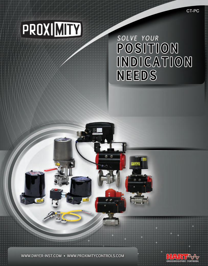
NOTE:
Each item (model, range, part number, etc.) is discountedindependently. In an order for more than one item, differentitems cannot be combined to earn a greater discount.
Most items are subject to STANDARD schedule at right.
Prices followed by the symbol b are subject to discountsper schedule B.
Certain items such as repairs, repair parts, EXPL and WP
housings, prices followed by the symbol n, special scaleand tag charges are priced at net and earn no discount.
INDUSTRIAL DISCOUNT SCHEDULE*
QUANTITYOF EACH
ITEM
1-24
25-99
100-249
250-499
500-Up
Net
5%
10%
15%
20%
Net
Net
5%
10%
15%
DISCOUNTS
STANDARD SCHEDULE B
*Please contact us for discount schedules for other account types.
Dwyer Instruments, Inc. - Discount Schedule
STANDARD TERMS & CONDITIONS OF SALE
003_Layout 2 1/7/14 1:01 PM Page 1
PROXIMITY CONTROLS, A Division of Dwyer Instruments, Inc. | 1431 State Hwy 210 E, Fergus Falls, MN 565374
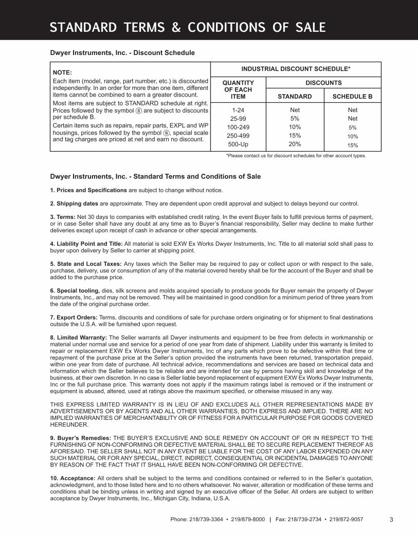
MARK SERIES . . . . . . . . . . . . . . . . . . . . . . . . . . . . . . . . . . . . . . . . . . . . . . . . . . . . . . . . . . . . . . . . . . . . . . . . . . . . . . . . . . . .5-12
OVERVIEW . . . . . . . . . . . . . . . . . . . . . . . . . . . . . . . . . . . . . . . . . . . . . . . . . . . . . . . . . . . . . . . . . . . . . . . . . . . . . . . . . . . . . . .5-6
MARK 1, ROTARY POSITION INDICATOR . . . . . . . . . . . . . . . . . . . . . . . . . . . . . . . . . . . . . . . . . . . . . . . . . . . . . . . . . . . . . . . .7
MARK 3, ROTARY POSITION INDICATOR . . . . . . . . . . . . . . . . . . . . . . . . . . . . . . . . . . . . . . . . . . . . . . . . . . . . . . . . . . . . . . . .8
MARK 4, ROTARY POSITION INDICATOR . . . . . . . . . . . . . . . . . . . . . . . . . . . . . . . . . . . . . . . . . . . . . . . . . . . . . . . . . . . . . . . .9
SPECIFICATIONS . . . . . . . . . . . . . . . . . . . . . . . . . . . . . . . . . . . . . . . . . . . . . . . . . . . . . . . . . . . . . . . . . . . . . . . . . . . . . . . . . . .10
MODEL CHART . . . . . . . . . . . . . . . . . . . . . . . . . . . . . . . . . . . . . . . . . . . . . . . . . . . . . . . . . . . . . . . . . . . . . . . . . . . . . . . . . . . .11
MOUNTING KITS . . . . . . . . . . . . . . . . . . . . . . . . . . . . . . . . . . . . . . . . . . . . . . . . . . . . . . . . . . . . . . . . . . . . . . . . . . . . . . . . . . .12
SERIES VPI, VALVE POSITION INDICATOR . . . . . . . . . . . . . . . . . . . . . . . . . . . . . . . . . . . . . . . . . . . . . . . . . . . . . . . . . . . . . .13
SERIES QV, QUICK-VIEW® VALVE POSITION INDICATOR/SWITCH . . . . . . . . . . . . . . . . . . . . . . . . . . . . . . . . . . . . . . . . . .14
SERIES DT, DETECTOR POSITION SENSOR . . . . . . . . . . . . . . . . . . . . . . . . . . . . . . . . . . . . . . . . . . . . . . . . . . . . . . . . . . . .15
SERIES VPS, VALVE POSITION SENSOR . . . . . . . . . . . . . . . . . . . . . . . . . . . . . . . . . . . . . . . . . . . . . . . . . . . . . . . . . . . . . . .16
SERIES VPT, VALVE POSITION TRANSMITTER . . . . . . . . . . . . . . . . . . . . . . . . . . . . . . . . . . . . . . . . . . . . . . . . . . . . . . . . . .16
004_Layout 2 1/7/14 1:03 PM Page 1
5Phone: 218/739-3364 • 219/879-8000 | Fax: 218/739-2734 • 219/872-9057
POSITIO
N INDICATORS/SWITCHES/TRANSMITTERS
Mark 1 – Magnetic Coupling
Cutaway Model 12VDOJ2
Series
Mark
Environmentally sealed for corrosive areas.
Mark 3 – Multi Turn
Mark 4 Thru-Shaft
Cutaway Model 42RDOJ2
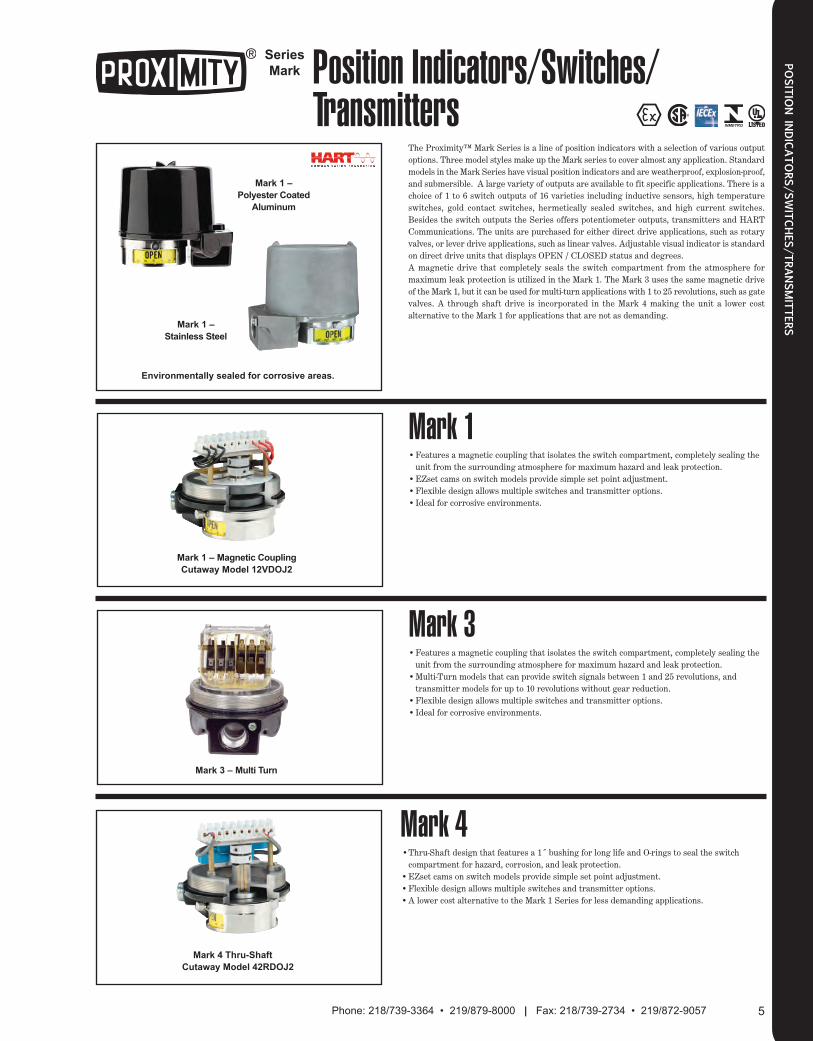
The Proximity™ Mark Series is a line of position indicators with a selection of various outputoptions. Three model styles make up the Mark series to cover almost any application. Standardmodels in the Mark Series have visual position indicators and are weatherproof, explosion-proof,and submersible. A large variety of outputs are available to fit specific applications. There is achoice of 1 to 6 switch outputs of 16 varieties including inductive sensors, high temperatureswitches, gold contact switches, hermetically sealed switches, and high current switches.Besides the switch outputs the Series offers potentiometer outputs, transmitters and HARTCommunications. The units are purchased for either direct drive applications, such as rotaryvalves, or lever drive applications, such as linear valves. Adjustable visual indicator is standardon direct drive units that displays OPEN / CLOSED status and degrees.A magnetic drive that completely seals the switch compartment from the atmosphere formaximum leak protection is utilized in the Mark 1. The Mark 3 uses the same magnetic driveof the Mark 1, but it can be used for multi-turn applications with 1 to 25 revolutions, such as gatevalves. A through shaft drive is incorporated in the Mark 4 making the unit a lower costalternative to the Mark 1 for applications that are not as demanding.
•Features a magnetic coupling that isolates the switch compartment, completely sealing the unit from the surrounding atmosphere for maximum hazard and leak protection.
•EZset cams on switch models provide simple set point adjustment.•Flexible design allows multiple switches and transmitter options.•Ideal for corrosive environments.
•Features a magnetic coupling that isolates the switch compartment, completely sealing the unit from the surrounding atmosphere for maximum hazard and leak protection.
•Multi-Turn models that can provide switch signals between 1 and 25 revolutions, and transmitter models for up to 10 revolutions without gear reduction.
•Flexible design allows multiple switches and transmitter options.•Ideal for corrosive environments.
•Thru-Shaft design that features a 1˝ bushing for long life and O-rings to seal the switch compartment for hazard, corrosion, and leak protection.
•EZset cams on switch models provide simple set point adjustment.•Flexible design allows multiple switches and transmitter options.•A lower cost alternative to the Mark 1 Series for less demanding applications.
Mark 1
Mark 3
Mark 4
Mark 1 –
Stainless Steel
Mark 1 –
Polyester Coated
Aluminum
Position Indicators/Switches/Transmitters
005_Layout 2 1/7/14 1:04 PM Page 1
PROXIMITY CONTROLS, A Division of Dwyer Instruments, Inc. | 1431 State Hwy 210 E, Fergus Falls, MN 565376
POSITIO
N INDICATORS/SWITCHES/TRANSMITTERS
Series
Mark Position Indicators/Switches/Transmitters
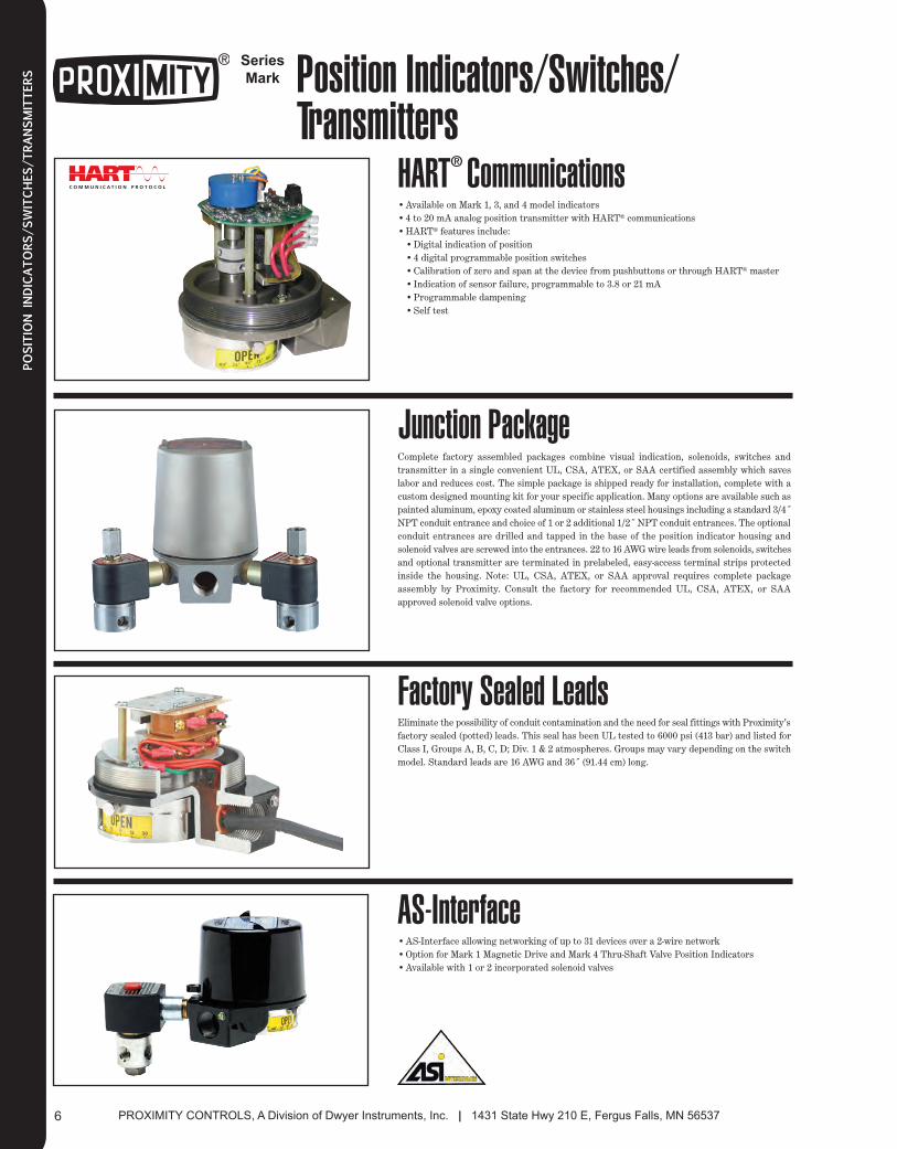
Complete factory assembled packages combine visual indication, solenoids, switches andtransmitter in a single convenient UL, CSA, ATEX, or SAA certified assembly which saveslabor and reduces cost. The simple package is shipped ready for installation, complete with acustom designed mounting kit for your specific application. Many options are available such aspainted aluminum, epoxy coated aluminum or stainless steel housings including a standard 3/4˝NPT conduit entrance and choice of 1 or 2 additional 1/2˝ NPT conduit entrances. The optionalconduit entrances are drilled and tapped in the base of the position indicator housing andsolenoid valves are screwed into the entrances. 22 to 16 AWG wire leads from solenoids, switchesand optional transmitter are terminated in prelabeled, easy-access terminal strips protectedinside the housing. Note: UL, CSA, ATEX, or SAA approval requires complete packageassembly by Proximity. Consult the factory for recommended UL, CSA, ATEX, or SAAapproved solenoid valve options.
Eliminate the possibility of conduit contamination and the need for seal fittings with Proximity’sfactory sealed (potted) leads. This seal has been UL tested to 6000 psi (413 bar) and listed forClass I, Groups A, B, C, D; Div. 1 & 2 atmospheres. Groups may vary depending on the switchmodel. Standard leads are 16 AWG and 36˝ (91.44 cm) long.
•AS-Interface allowing networking of up to 31 devices over a 2-wire network•Option for Mark 1 Magnetic Drive and Mark 4 Thru-Shaft Valve Position Indicators•Available with 1 or 2 incorporated solenoid valves
Junction Package
Factory Sealed Leads
AS-Interface
•Available on Mark 1, 3, and 4 model indicators•4 to 20 mA analog position transmitter with HART® communications•HART® features include:•Digital indication of position•4 digital programmable position switches•Calibration of zero and span at the device from pushbuttons or through HART® master•Indication of sensor failure, programmable to 3.8 or 21 mA•Programmable dampening•Self test
HART® Communications
006_Layout 2 1/7/14 1:05 PM Page 1

7Phone: 218/739-3364 • 219/879-8000 | Fax: 218/739-2734 • 219/872-9057
POSITIO
N INDICATORS/SWITCHES/TRANSMITTERS
Series
Mark 1 Rotary Position IndicatorMagnetically Coupled Switches and TransmittersIdeal for Corrosive Environments
1[25.40]
CLEARANCE REQUIREDFOR COVER REMOVAL LEVER DRIVE
DIRECT DRIVE
4-1/4[107.95]
3[76.20]
1-1/6[26.99]
5/16[7.94].249 .001
[6.32 .03]
2-3/8[60.33]
1-1/4[31.75]
5-5/16[150.81] *4-9/16
[115.89]
#6-32 UNC THREADX 1/4 [6.35] DEEP
4-7/8[123.83]
2-3/8[60.33]
1-9/16[39.69]
3/4 NPTCONDUIT
CONNECTIONOR OPTIONAL
M25
118 Ø4-7/16[112.71]
1/4[6.35]TYP
Ø1/8 [3.18] PINTYP 2 PLACES
1/2 NPT CONDUIT CONNECTION (OPTIONAL)OR OPTIONAL M20 2 PLACES
1/4-20 UNC THREAD X 7/16 [11.11] DPTYP 2 PLACES
*FOR MODELS 11, 12, 41, 42, 61 & 62
1-1/2[38.10]
Cutaway View Model 12VD0J2 Shown
BENEFITS
• The switch compartment is completely isolated from atmosphere.
• A magnetic coupling completely seals the switch compartment for maximum
hazard and leak protection, (IP68 and submersible to 50 feet indefinitely).
• Set screw cams provide infinite adjustment, and user-friendly manual cams
provide single-step rotational adjustment and locking set screw.
• Flexible design allows multiple mechanical or proximity switches and
transmitter option(s).
• Adjustable stainless steel visual indicator with scale is standard for quarter
turn direct drive applications.
• Housing options include 1, 2 or 3 conduit entrances, junction package,
terminal strip and solenoid valve option(s).
• Mounting hardware is available in plated or stainless steel material for your
specific requirements, including rotary, linear and NAMUR mounting
hardware.
APPLICATIONS
• Rotary valve actuators and dampers
• Linear valve actuators and cylinders
• Manual valves
• Gear operators
• Positioners
SPECIFICATIONS
Electrical Connections: Screw terminal. Optional factory sealed leads that
are 36˝ (914.4 mm) of 16 AWG.
Conduit Connection: 3/4˝ female NPT standard. Optional one or two 1/2˝
female NPT. M25 and M20 optional (standard on SAA certified products).
Mounting Orientation: Not position sensitive.
Minimum Rotation Travel: 5°.
Maximum Rotation Travel: 360°.
Operational Life: Over 10,000,000 cycles.
Maximum Altitude: 2000 meters.
Weight: 3 to 6 lb (1.5 to 3.0 kg).
Approvals: ATEX, CSA, IECEx, INMETRO, UL.
POPULAR MODELS
See model chart on page 11.
Model
12AD0
12AL0
14AD0
15VD0
19OD6
Description
Mark 1 with 2 SPDT switches, direct drive
Mark 1 with 2 SPDT switches, lever drive
Mark 1 with 4 SPDT switches, direct drive
Mark 1 with 2 SPDT switches, position transmitter, direct drive
Stainless Steel Mark 1, Transmitter with HART, direct drive
007_Layout 2 1/7/14 1:05 PM Page 1
PROXIMITY CONTROLS, A Division of Dwyer Instruments, Inc. | 1431 State Hwy 210 E, Fergus Falls, MN 565378
POSITIO
N INDICATORS/SWITCHES/TRANSMITTERS
Series
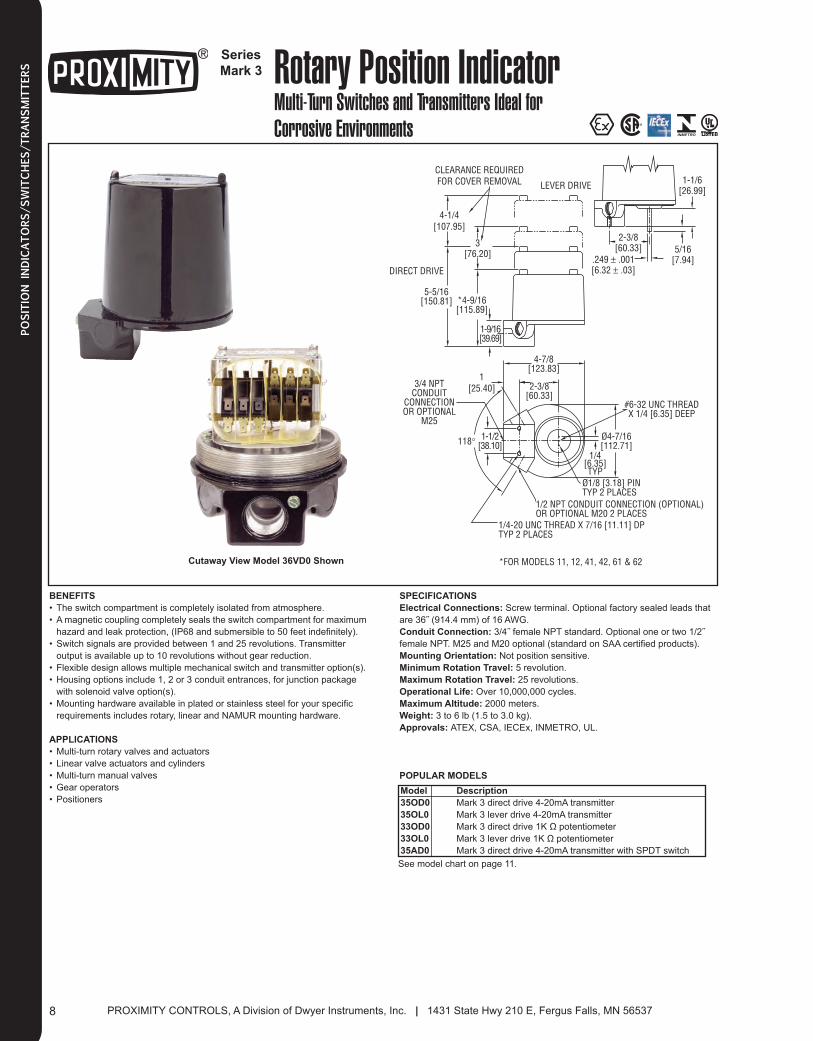
Mark 3 Rotary Position IndicatorMulti-Turn Switches and Transmitters Ideal for Corrosive Environments
Cutaway View Model 36VD0 Shown
1[25.40]
CLEARANCE REQUIREDFOR COVER REMOVAL LEVER DRIVE
DIRECT DRIVE
4-1/4[107.95]
3[76.20]
1-1/6[26.99]
5/16[7.94].249 ± .001
[6.32 ± .03]
2-3/8[60.33]
5-5/16[150.81] *4-9/16
[115.89]
#6-32 UNC THREADX 1/4 [6.35] DEEP
4-7/8[123.83]
2-3/8[60.33]
1-9/16[39.69]
3/4 NPTCONDUIT
CONNECTIONOR OPTIONAL
M25
118° Ø4-7/16[112.71]
1/4[6.35]TYP
Ø1/8 [3.18] PINTYP 2 PLACES
1/2 NPT CONDUIT CONNECTION (OPTIONAL)OR OPTIONAL M20 2 PLACES
1/4-20 UNC THREAD X 7/16 [11.11] DPTYP 2 PLACES
*FOR MODELS 11, 12, 41, 42, 61 & 62
1-1/2[38.10]
BENEFITS
• The switch compartment is completely isolated from atmosphere.
• A magnetic coupling completely seals the switch compartment for maximum
hazard and leak protection, (IP68 and submersible to 50 feet indefinitely).
• Switch signals are provided between 1 and 25 revolutions. Transmitter
output is available up to 10 revolutions without gear reduction.
• Flexible design allows multiple mechanical switch and transmitter option(s).
• Housing options include 1, 2 or 3 conduit entrances, for junction package
with solenoid valve option(s).
• Mounting hardware available in plated or stainless steel for your specific
requirements includes rotary, linear and NAMUR mounting hardware.
APPLICATIONS
• Multi-turn rotary valves and actuators
• Linear valve actuators and cylinders
• Multi-turn manual valves
• Gear operators
• Positioners
SPECIFICATIONS
Electrical Connections: Screw terminal. Optional factory sealed leads that
are 36˝ (914.4 mm) of 16 AWG.
Conduit Connection: 3/4˝ female NPT standard. Optional one or two 1/2˝
female NPT. M25 and M20 optional (standard on SAA certified products).
Mounting Orientation: Not position sensitive.
Minimum Rotation Travel: 5 revolution.
Maximum Rotation Travel: 25 revolutions.
Operational Life: Over 10,000,000 cycles.
Maximum Altitude: 2000 meters.
Weight: 3 to 6 lb (1.5 to 3.0 kg).
Approvals: ATEX, CSA, IECEx, INMETRO, UL.
Model
35OD0
35OL0
33OD0
33OL0
35AD0
POPULAR MODELS
See model chart on page 11.
Description
Mark 3 direct drive 4-20mA transmitter
Mark 3 lever drive 4-20mA transmitter
Mark 3 direct drive 1K Ω potentiometer
Mark 3 lever drive 1K Ω potentiometer
Mark 3 direct drive 4-20mA transmitter with SPDT switch
008_Layout 2 1/7/14 1:10 PM Page 1
9Phone: 218/739-3364 • 219/879-8000 | Fax: 218/739-2734 • 219/872-9057
POSITIO
N INDICATORS/SWITCHES/TRANSMITTERS
Series
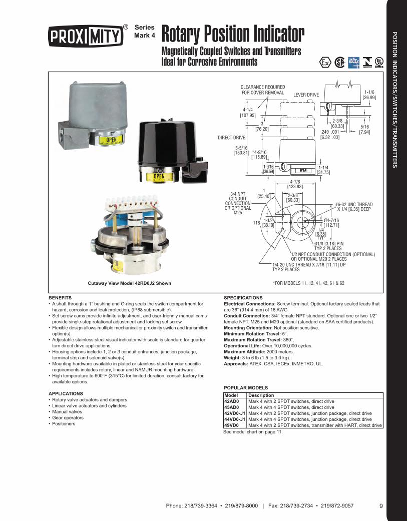
Mark 4 Rotary Position IndicatorMagnetically Coupled Switches and TransmittersIdeal for Corrosive Environments
1[25.40]
CLEARANCE REQUIREDFOR COVER REMOVAL LEVER DRIVE
DIRECT DRIVE
4-1/4[107.95]
3[76.20]
1-1/6[26.99]
5/16[7.94].249 .001
[6.32 .03]
2-3/8[60.33]
1-1/4[31.75]
5-5/16[150.81] *4-9/16
[115.89]
#6-32 UNC THREADX 1/4 [6.35] DEEP
4-7/8[123.83]
2-3/8[60.33]
1-9/16[39.69]
3/4 NPTCONDUIT
CONNECTIONOR OPTIONAL
M25
118 Ø4-7/16[112.71]
1/4[6.35]TYP
Ø1/8 [3.18] PINTYP 2 PLACES
1/2 NPT CONDUIT CONNECTION (OPTIONAL)OR OPTIONAL M20 2 PLACES
1/4-20 UNC THREAD X 7/16 [11.11] DPTYP 2 PLACES
*FOR MODELS 11, 12, 41, 42, 61 & 62
1-1/2[38.10]
Cutaway View Model 42RD0J2 Shown
BENEFITS
• A shaft through a 1˝ bushing and O-ring seals the switch compartment for
hazard, corrosion and leak protection, (IP68 submersible).
• Set screw cams provide infinite adjustment, and user-friendly manual cams
provide single-step rotational adjustment and locking set screw.
• Flexible design allows multiple mechanical or proximity switch and transmitter
option(s).
• Adjustable stainless steel visual indicator with scale is standard for quarter
turn direct drive applications.
• Housing options include 1, 2 or 3 conduit entrances, junction package,
terminal strip and solenoid valve(s).
• Mounting hardware available in plated or stainless steel for your specific
requirements includes rotary, linear and NAMUR mounting hardware.
• High temperature to 600°F (315°C) for limited duration, consult factory for
available options.
APPLICATIONS
• Rotary valve actuators and dampers
• Linear valve actuators and cylinders
• Manual valves
• Gear operators
• Positioners
SPECIFICATIONS
Electrical Connections: Screw terminal. Optional factory sealed leads that
are 36˝ (914.4 mm) of 16 AWG.
Conduit Connection: 3/4˝ female NPT standard. Optional one or two 1/2˝
female NPT. M25 and M20 optional (standard on SAA certified products).
Mounting Orientation: Not position sensitive.
Minimum Rotation Travel: 5°.
Maximum Rotation Travel: 360°.
Operational Life: Over 10,000,000 cycles.
Maximum Altitude: 2000 meters.
Weight: 3 to 6 lb (1.5 to 3.0 kg).
Approvals: ATEX, CSA, IECEx, INMETRO, UL.
POPULAR MODELS
See model chart on page 11.
Model
42AD0
45AD0
42VD0-J1
44VD0-J1
49VD0
Description
Mark 4 with 2 SPDT switches, direct drive
Mark 4 with 4 SPDT switches, direct drive
Mark 4 with 2 SPDT switches, junction package, direct drive
Mark 4 with 4 SPDT switches, junction package, direct drive
Mark 4 with 2 SPDT switches, transmitter with HART, direct drive
009_Layout 2 1/7/14 1:14 PM Page 1
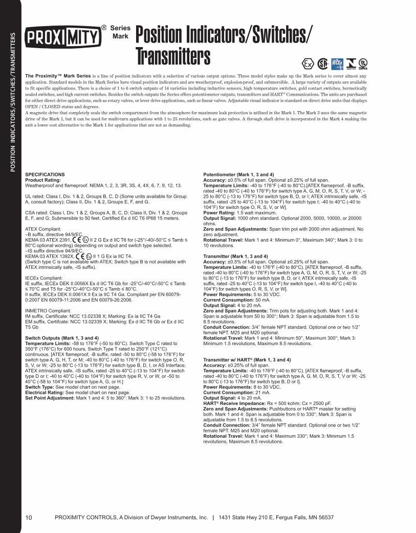
SPECIFICATIONSProduct Rating:Weatherproof and flameproof. NEMA 1, 2, 3, 3R, 3S, 4, 4X, 6, 7, 9, 12, 13.
UL rated: Class I, Div. 1 & 2, Groups B, C, D (Some units available for GroupA, consult factory); Class II, Div. 1 & 2, Groups E, F, and G.
CSA rated: Class I, Div. 1 & 2, Groups A, B, C, D; Class II, Div. 1 & 2, GroupsE, F, and G; Submersible to 50 feet. Certified Ex d IIC T6 IP68 15 meters.
ATEX Compliant: –B suffix, directive 94/9/EC, KEMA 03 ATEX 2391, II 2 G Ex d IIC T6 for (-25°/-40/-50°C ≤ Tamb ≤80°C optional wording) depending on output and switch type selected. –IS suffix directive 94/9/EC, KEMA 03 ATEX 1392X, II 1 G Ex ia IIC T4.(Switch type C is not available with ATEX; Switch type B is not available withATEX intrinsically safe, -IS suffix).
IECEx Compliant:IE suffix, IECEx DEK II.0056X Ex d IIC T6 Gb for -25°C/-40°C/-50°C ≤ Tamb≤ 70°C and T5 for -25°C/-40°C/-50°C ≤ Tamb ≤ 80°C.II suffix, IECEx DEK II.0061X II Ex ia IIC T4 Ga. Compliant per EN 60079-0:2007 EN 60079-11:2006 and EN 60079-26:2006.
INMETRO Compliant:IM suffix, Certificate: NCC 13.02338 X; Marking: Ex ia IIC T4 GaEM suffix, Certifcate: NCC 13.02339 X; Marking: Ex d IIC T6 Gb or Ex d IICT5 Gb
Switch Outputs (Mark 1, 3 and 4)Temperature Limits: -58 to 176°F (-50 to 80°C). Switch Type C rated to350°F (176°C) for 600 hours, Switch Type T rated to 250°F (121°C)continuous. [ATEX flameproof, -B suffix, rated -50 to 80°C (-58 to 176°F) forswitch type A, G, H, T, or M; -40 to 80°C (-40 to 176°F) for switch type O, R,S, V, or W; -25 to 80°C (-13 to 176°F) for switch type B, D, I, or AS Interface;ATEX intrinsically safe, -IS suffix, rated -25 to 40°C (-13 to 104°F) for switchtype D or I; -40 to 40°C (-40 to 104°F) for switch type R, V, or W, or -50 to40°C (-58 to 104°F) for switch type A, G, or H.]Switch Type: See model chart on next page.Electrical Rating: See model chart on next page.Set Point Adjustment: Mark 1 and 4: 5 to 360°; Mark 3: 1 to 25 revolutions.
Potentiometer (Mark 1, 3 and 4)Accuracy: ±0.5% of full span. Optional ±0.25% of full span.Temperature Limits: -40 to 176°F (-40 to 80°C).[ATEX flameproof, -B suffix,rated -40 to 80°C (-40 to 176°F) for switch type A, G, M, O, R, S, T, V, or W; -25 to 80°C (-13 to 176°F) for switch type B, D, or I; ATEX intrinsically safe, -ISsuffix, rated -25 to 40°C (-13 to 104°F) for switch type I; -40 to 40°C (-40 to104°F) for switch type O, R, S, V, or W].Power Rating: 1.5 watt maximum. Output Signal: 1000 ohm standard. Optional 2000, 5000, 10000, or 20000ohms.Zero and Span Adjustments: Span trim pot with 2000 ohm adjustment. Nozero adjustment.Rotational Travel: Mark 1 and 4: Minimum 0°, Maximum 340°; Mark 3: 0 to10 revolutions.
Transmitter (Mark 1, 3 and 4)Accuracy: ±0.5% of full span. Optional ±0.25% of full span.Temperature Limits: -40 to 176°F (-40 to 80°C). [ATEX flameproof, -B suffix,rated -40 to 80°C (-40 to 176°F) for switch type A, G, M, O, R, S, T, V, or W; -25to 80°C (-13 to 176°F) for switch type B, D, or I; ATEX intrinsically safe, -ISsuffix, rated -25 to 40°C (-13 to 104°F) for switch type I, -40 to 40°C (-40 to104°F) for switch types O, R, S, V, or W].Power Requirements: 5 to 30 VDC.Current Consumption: 50 mA. Output Signal: 4 to 20 mA.Zero and Span Adjustments: Trim pots for adjusting both. Mark 1 and 4:Span is adjustable from 50 to 300°; Mark 3: Span is adjustable from 1.5 to8.5 revolutions. Conduit Connection: 3/4˝ female NPT standard. Optional one or two 1/2˝ female NPT. M25 and M20 optional.Rotational Travel: Mark 1 and 4: Minimum 50°, Maximum 300°; Mark 3:Minimum 1.5 revolutions, Maximum 8.5 revolutions.
Transmitter w/ HART® (Mark 1, 3 and 4)Accuracy: ±0.25% of full span.Temperature Limits: -40 to 176°F (-40 to 80°C). [ATEX flameproof, -B suffix,rated -40 to 80°C (-40 to 176°F) for switch type A, G, M, O, R, S, T, V or W; -25to 80°C (-13 to 176°F) for switch type B, D or I].Power Requirements: 8 to 30 VDC.Current Consumption: 21 mA. Output Signal: 4 to 20 mA.HART® Receive Impedance: Rx = 500 kohm; Cx = 2500 pF.Zero and Span Adjustments: Pushbuttons or HART® master for settingboth. Mark 1 and 4: Span is adjustable from 0 to 330°; Mark 3: Span isadjustable from 1.5 to 8.5 revolutions. Conduit Connection: 3/4˝ female NPT standard. Optional one or two 1/2˝ female NPT. M25 and M20 optional.Rotational Travel: Mark 1 and 4: Maximum 330°; Mark 3: Minimum 1.5revolutions, Maximum 8.5 revolutions.
PROXIMITY CONTROLS, A Division of Dwyer Instruments, Inc. | 1431 State Hwy 210 E, Fergus Falls, MN 5653710
POSITIO
N INDICATORS/SWITCHES/TRANSMITTERS
Series
Mark Position Indicators/Switches/Transmitters
The Proximity™ Mark Series is a line of position indicators with a selection of various output options. Three model styles make up the Mark series to cover almost anyapplication. Standard models in the Mark Series have visual position indicators and are weatherproof, explosion-proof, and submersible. A large variety of outputs are availableto fit specific applications. There is a choice of 1 to 6 switch outputs of 14 varieties including inductive sensors, high temperature switches, gold contact switches, hermeticallysealed switches, and high current switches. Besides the switch outputs the Series offers potentiometer outputs, transmitters and HART® Communications. The units are purchasedfor either direct drive applications, such as rotary valves, or lever drive applications, such as linear valves. Adjustable visual indicator is standard on direct drive units that displaysOPEN / CLOSED status and degrees.A magnetic drive that completely seals the switch compartment from the atmosphere for maximum leak protection is utilized in the Mark 1. The Mark 3 uses the same magneticdrive of the Mark 1, but it can be used for multi-turn applications with 1 to 25 revolutions, such as gate valves. A through shaft drive is incorporated in the Mark 4 making theunit a lower cost alternative to the Mark 1 for applications that are not as demanding.
010_Layout 2 1/7/14 1:14 PM Page 1

11Phone: 218/739-3364 • 219/879-8000 | Fax: 218/739-2734 • 219/872-9057
POSITIO
N INDICATORS/SWITCHES/TRANSMITTERS
Series
Mark Position Indicators/Switches/Transmitters
Switch Type
& Rating
Construction
1
3
4
1
2
3
32
35
310
320
4
5
6
7
8
9
A
B
C
D
G
H
I
M
0
R
S
T
V
W
Mark 1, Magnetic Coupling
Mark 3, Multi-Turn
Mark 4, Thru-Shaft
1 Switch
2 Switches
Potentiometer, 1 K Ω. Available with switches, see note below.*
Potentiometer, 2 K Ω. Available with switches, see note below.*
Potentiometer, 5 K Ω. Available with switches, see note below.*
Potentiometer, 10 K Ω. Available with switches , see note below.*
Potentiometer, 20 K Ω. Available with switches, see note below.*
4 Switches
Transmitter, 4 to 20 mA. Available with switches, see note below.*
6 Switches. Available with Switch Types B, C, I, R, V, W.
AS-interface and 1 Switch. Available with Switch Types B, I, R, W.
AS-interface and 2 Switches. Available with Switch Types B, I, R, W.
HART® Transmitter. Available with switches, see note below.*
SPDT Snap, Rated: 15 A @ 125/250/480 VAC (~) ; 1/8 hp @ 125 VAC (~),
1/4 hp @ 250 VAC (~), 1/2 A @ 125 VDC , 1/4 A @ 250 VDC .
Inductive Sensor. 10 to 30 VDC . Load: 0.1 A.
SPDT High Temperature Snap, 350°F (176°C) for 600 hours, Rated: 15.1 A @ 125/250/277 VAC (~).
DPDT Snap, Rated: 10 A @ 125/250 VAC (~), 0.3 A @ 125 VDC , 0.15 A @ 250 VDC .
SPDT Gold Contact Snap, Rated: 1 A @ 125 VAC (~).
SPDT Hermetically Sealed Snap, Rated: 1 A @ 125 VAC .
NAMUR Inductive Sensor. 15 mA max @ 5-25 VDC (~).
SPDT Magnetic Blow-Out, Rated: 10 A @ 125 VAC (~)/VDC , 1/4 hp @ 125 VAC (~)/VDC .
No Switches
SPDT Hermetically Sealed Reed, Rated: 2 A @ 125 VAC (~), 2 A @ 24 VDC .
SPDT Snap, Rated: 4A @ 125/250 VAC (~).
SPDT High Temperature Snap, 250°F (121°C) Continuous, Rated: 5 A @ 125/250/480 VAC (~).
SPDT Snap, Rated: 10 A @ 125/250 VAC (~), 1/3 hp @ 125/250 VAC (~),
1/2 A @ 125 VDC , 1/4 A @ 250 VDC , 4 A @ 125 VAC (~) (tungsten).
SPDT Gold Contact Snap, Rated 0.1 A @ 125 VAC (~).
Available Options “A”
signifies available with
corresponding
construction style.
Mark1 3 4
--
A
A
A
A
A
A
A
A
A
--
--
A
A
A
A
A
A
A
A
A
A
A
A
A
A
A
A
A
A
A
A
A
A
A
A
A
A
A
(–)--
(–)--
(–)--
(–)--
(–)--
(–)--
(–)--
(–)--
(–)--(–)--
(–)--
A
A
A
A
A
A
A
A
A
A
A
A
A
A
A
--
A
A
A
--
--
A
A
--
--
A
A
A
A
A
A
A
A
A
A
A
A
A
A
A
A
A
*Note: Mark 1 and 4 potentiometer and transmitter outputs will have no switches when ordered with switch type 0; 2 switches if ordered with switch types B, C, I, R,
V, or W; and 4 switches if ordered with switch type S. Mark 3 potentiometer and transmitter outputs will have no switches when ordered with switch type 0, and 2
switches if ordered with switch types A, G, M or T.
††Minimum temperature depends on output and switch type selected.
Driving Method
Enclosure
Options
D
L
J1
J2
SV1
SV2
MT
B
IS
IE
II
IM
EM
Junction Package with One 1/2˝ NPT Female Conduit Connection and Terminal Strip.
Junction Package with Two 1/2˝ NPT Female Conduit Connection and Terminal Strip.
1 Attached Solenoid Valve (Must be ordered with J1 option).
2 Attached Solenoid Valves (Must be ordered with J2 option).
Metric Threaded Conduit Connection, M25 (M20 for optional J1 and J2 connections).
Directive 94/9/EC, KEMA 03 ATEX 2391, II 2 G Ex d IIC T6 (-25/-40/-50°C†† ≤ Tamb ≤ 70°C)
(T5 (-25/-40/-50°C†† ≤ Tamb ≤ 80°C) optional wording).
Directive 94/9/EC, KEMA 03 ATEX 1392 x, II 1 G Ex ia IIC T4.
IECEx DEK II.0056X Ex d IIC T6 Gb for -25°C/-40°C/-50°C ≤ Tamb ≤ 70°C and T5 for -25°C/-40°C/
-50°C ≤ Tamb ≤ 80°C.
IECEx DEK II.0061X II Ex ia IIC T4 Ga. Compliant per EN 60079-0:2007 EN 60079-11:2006 and EN
60079-26:2006.
Certificate: NCC 13.02338 X; Marking: Ex ia IIC T4 Ga
Certificate: NCC 13.02339 X; Marking: Ex d IIC T6 Gb or Ex d IIC T5 Gb
A
A
A
A
A
A
A
A
A
A
A
A
A
A
A
A
A
A
A
A
A
A
A
A
A
A
A
A
--
--
A
A
A
A
A
A
A
A
A
A
A
A
A
A
A
A
A
A
0
1
6
Aluminum, Painted Black
Aluminum, Painted White Epoxy with SS trim
Cast 316 SS
Direct Drive (Yoke) with SS Visual Indicator.
Lever Drive (Shaft), No Visual Indicator.
Output Type
Mark Series mounted to an actuator
011_Layout 2 1/7/14 1:15 PM Page 1
PROXIMITY CONTROLS, A Division of Dwyer Instruments, Inc. | 1431 State Hwy 210 E, Fergus Falls, MN 5653712
POSITIO
N INDICATORS/SWITCHES/TRANSMITTERS
Series
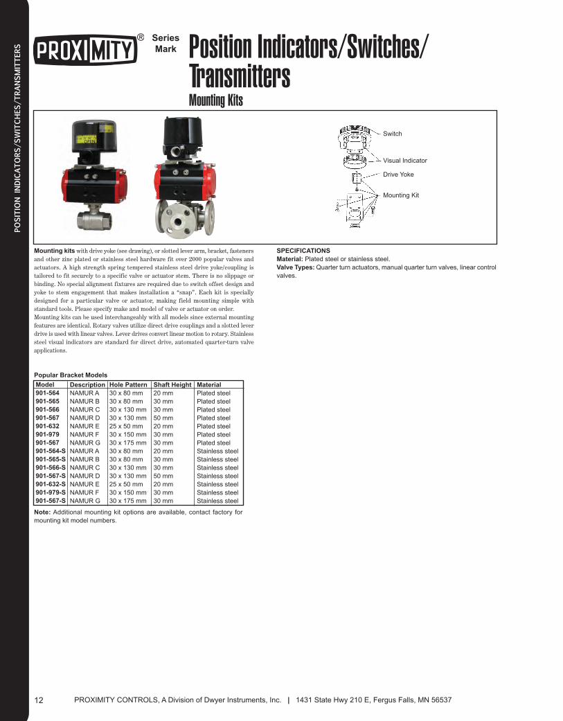
Mark Position Indicators/Switches/TransmittersMounting Kits
Switch
Visual Indicator
Drive Yoke
Mounting Kit
Mounting kits with drive yoke (see drawing), or slotted lever arm, bracket, fastenersand other zinc plated or stainless steel hardware fit over 2000 popular valves andactuators. A high strength spring tempered stainless steel drive yoke/coupling istailored to fit securely to a specific valve or actuator stem. There is no slippage orbinding. No special alignment fixtures are required due to switch offset design andyoke to stem engagement that makes installation a “snap”. Each kit is speciallydesigned for a particular valve or actuator, making field mounting simple withstandard tools. Please specify make and model of valve or actuator on order.Mounting kits can be used interchangeably with all models since external mountingfeatures are identical. Rotary valves utilize direct drive couplings and a slotted leverdrive is used with linear valves. Lever drives convert linear motion to rotary. Stainlesssteel visual indicators are standard for direct drive, automated quarter-turn valveapplications.
Model
901-564
901-565
901-566
901-567
901-632
901-979
901-567
901-564-S
901-565-S
901-566-S
901-567-S
901-632-S
901-979-S
901-567-S
SPECIFICATIONS
Material: Plated steel or stainless steel.
Valve Types: Quarter turn actuators, manual quarter turn valves, linear control
valves.
Popular Bracket Models
Description
NAMUR A
NAMUR B
NAMUR C
NAMUR D
NAMUR E
NAMUR F
NAMUR G
NAMUR A
NAMUR B
NAMUR C
NAMUR D
NAMUR E
NAMUR F
NAMUR G
Note: Additional mounting kit options are available, contact factory for
mounting kit model numbers.
Hole Pattern
30 x 80 mm
30 x 80 mm
30 x 130 mm
30 x 130 mm
25 x 50 mm
30 x 150 mm
30 x 175 mm
30 x 80 mm
30 x 80 mm
30 x 130 mm
30 x 130 mm
25 x 50 mm
30 x 150 mm
30 x 175 mm
Shaft Height
20 mm
30 mm
30 mm
50 mm
20 mm
30 mm
30 mm
20 mm
30 mm
30 mm
50 mm
20 mm
30 mm
30 mm
Material
Plated steel
Plated steel
Plated steel
Plated steel
Plated steel
Plated steel
Plated steel
Stainless steel
Stainless steel
Stainless steel
Stainless steel
Stainless steel
Stainless steel
Stainless steel
012_Layout 2 1/7/14 1:16 PM Page 1

13Phone: 218/739-3364 • 219/879-8000 | Fax: 218/739-2734 • 219/872-9057
POSITIO
N INDICATORS/SWITCHES/TRANSMITTERS
Series
VPI Valve Position IndicatorLow Cost, Mechanical or Proximity Limit Switches
The Series VPI Rotary Valve Position Indicators are compact yet rugged forconfined and severe locations. These versatile units offer visual position indication aswell as two internal limit switches. The spring-loaded splined cams require no toolsfor a quick and precise adjustment. The Series VPI is available with mechanical orproximity limit switches. The mechanical models feature two SPDT limit switches.The proximity models feature two solid-state inductive limit switches eliminating theneed for the cams to make contact with the switches. The NEMA 6 (IP67) ratingensures protection against the ingress of liquid and debris.
SPECIFICATIONS
Minimum Rotation Travel: 60°.
Maximum Rotation Travel: 360°.
Temperature Limits: -4 to 176°F (-20 to 80°C).
Switch Type: VPI-M: (2) mechanical SPDT limit switches; VPI-P: (2)
inductive proximity limit switches.
Electrical Rating: VPI-M: AC: 3 A at 250 V, 5 A at 125 V; DC: 0.2 A at 250 V,
0.4 A at 125 V, 4 A at 30 V.
Power Requirements: VPI-P: 12 to 24 VDC, 30 VDC max.
Enclosure Material: Aluminum die-casting.
Electrical Connections: 8-contact screw terminal strip.
Conduit Connection: (2) 1/2˝ female NPT.
Enclosure Rating: NEMA 6 (IP67).
Mounting: NAMUR.
Weight: 1.9 lb (0.88 kg).
W4 W3
L1
L2
3-27/32[97.5]
1-61/64[49.8]
2-25/32[70.8]
3-51/64[96.5]
1/2 NPT
4-3/4[120.5]
H
Model
VPI-B01
VPI-B02
VPI-B03
VPI-B04
H in (mm)
1-13/64 [30]
1-19/64 [40.5]
1-19/64 [40.5]
2-3/8 [60.5]
L1 in (mm)
3-5/32 [80]
5-1/8 [130]
L2 in (mm)
3-15/16 [100]
5-29/32 [150]
W3 in (mm)
1-3/16 [30]
W4 in (mm)
2 [50]
Bracket Dimensions
Bracket
Model VPI mounted to an actuator
Model
VPI-M01
VPI-P01
VPI-B01
VPI-B02
VPI-B03
VPI-B04
Description
Rotary Valve Position Indicator,
Dual Mechanical SPDT, 1/2˝ NPT Conduit
Rotary Valve Position Indicator,
Dual Proximity SPDT, 1/2˝ NPT Conduit
NAMUR A, 30 x 80 mm hole pattern, 20 mm shaft height
NAMUR B, 30 x 80 mm hole pattern, 30 mm shaft height
NAMUR C, 30 x 130 mm hole pattern, 30 mm shaft height
NAMUR D, 30 x 130 mm hole pattern, 50 mm shaft height
013_Layout 2 1/7/14 1:19 PM Page 1
PROXIMITY CONTROLS, A Division of Dwyer Instruments, Inc. | 1431 State Hwy 210 E, Fergus Falls, MN 5653714
POSITIO
N INDICATORS/SWITCHES/TRANSMITTERS
Series
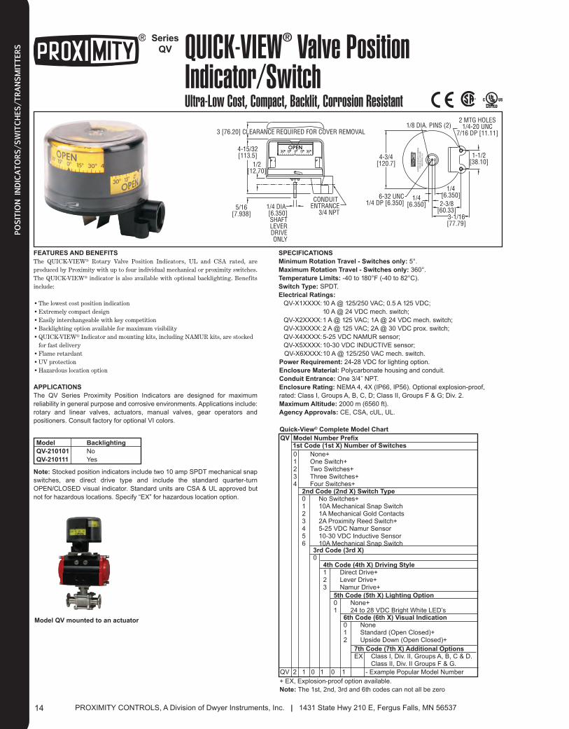
QV QUICK-VIEW® Valve PositionIndicator/SwitchUltra-Low Cost, Compact, Backlit, Corrosion Resistant
®
6-32 UNC1/4 DP [6.350]
1/4[6.350]
1/4[6.350]2-3/8
[60.33]3-1/16[77.79]
1-1/2[38.10]
2 MTG HOLES1/4-20 UNC
7/16 DP [11.11]
CONDUIT ENTRANCE
3/4 NPT
3 [76.20] CLEARANCE REQUIRED FOR COVER REMOVAL
4-15/32[113.5]
1/2[12.70]
5/16[7.938]
1/4 DIA.[6.350]SHAFTLEVERDRIVEONLY
1/8 DIA. PINS (2)
4-3/4[120.7]
A DW
YER
INST
RUM
ENTS
COM
PANY
FERG
US FA
LLS,
MN
5653
7M
ADE
IN T
HE U
.S.A
.
Note: Stocked position indicators include two 10 amp SPDT mechanical snap
switches, are direct drive type and include the standard quarter-turn
OPEN/CLOSED visual indicator. Standard units are CSA & UL approved but
not for hazardous locations. Specify “EX” for hazardous location option.
FEATuRES AND BENEFITS
The QUICK-VIEW® Rotary Valve Position Indicators, UL and CSA rated, areproduced by Proximity with up to four individual mechanical or proximity switches.The QUICK-VIEW® indicator is also available with optional backlighting. Benefitsinclude:
•The lowest cost position indication•Extremely compact design•Easily interchangeable with key competition•Backlighting option available for maximum visibility•QUICK-VIEW® Indicator and mounting kits, including NAMUR kits, are stocked
for fast delivery•Flame retardant•UV protection•Hazardous location option
APPLICATIONS
The QV Series Proximity Position Indicators are designed for maximum
reliability in general purpose and corrosive environments. Applications include:
rotary and linear valves, actuators, manual valves, gear operators and
positioners. Consult factory for optional VI colors.
SPECIFICATIONS
Minimum Rotation Travel - Switches only: 5°.
Maximum Rotation Travel - Switches only: 360°.
Temperature Limits: -40 to 180°F (-40 to 82°C).
Switch Type: SPDT.
Electrical Ratings:
QV-X1XXXX:10 A @ 125/250 VAC; 0.5 A 125 VDC;
10 A @ 24 VDC mech. switch;
QV-X2XXXX:1 A @ 125 VAC; 1A @ 24 VDC mech. switch;
QV-X3XXXX:2 A @ 125 VAC; 2A @ 30 VDC prox. switch;
QV-X4XXXX:5-25 VDC NAMUR sensor;
QV-X5XXXX:10-30 VDC INDUCTIVE sensor;
QV-X6XXXX:10 A @ 125/250 VAC mech. switch.
Power Requirement: 24-28 VDC for lighting option.
Enclosure Material: Polycarbonate housing and conduit.
Conduit Entrance: One 3/4˝ NPT.
Enclosure Rating: NEMA 4, 4X (IP66, IP56). Optional explosion-proof,
rated: Class I, Groups A, B, C, D; Class II, Groups F & G; Div. 2.
Maximum Altitude: 2000 m (6560 ft).
Agency Approvals: CE, CSA, cUL, UL.
0 None+1 One Switch+2 Two Switches+3 Three Switches+4 Four Switches+
2nd Code (2nd X) Switch Type0 No Switches+1 10A Mechanical Snap Switch2 1A Mechanical Gold Contacts3 2A Proximity Reed Switch+4 5-25 VDC Namur Sensor5 10-30 VDC Inductive Sensor6 10A Mechanical Snap Switch
4th Code (4th X) Driving Style1 Direct Drive+2 Lever Drive+3 Namur Drive+
5th Code (5th X) Lighting Option0 None+1 24 to 28 VDC Bright White LED’s
6th Code (6th X) Visual Indication0 None1 Standard (Open Closed)+2 Upside Down (Open Closed)+
7th Code (7th X) Additional OptionsEX Class I, Div. II, Groups A, B, C & D.
Class II, Div. II Groups F & G.
QV Model Number Prefix1st Code (1st X) Number of Switches
3rd Code (3rd X)0
QV 2 1 0 1 0 1 - Example Popular Model Number
+ EX, Explosion-proof option available.
Note: The 1st, 2nd, 3rd and 6th codes can not all be zero
Quick-View® Complete Model Chart
Model
QV-210101
QV-210111
Model QV mounted to an actuator
Backlighting
No
Yes
014_Layout 2 1/7/14 1:19 PM Page 1
15Phone: 218/739-3364 • 219/879-8000 | Fax: 218/739-2734 • 219/872-9057
POSITIO
N INDICATORS/SWITCHES/TRANSMITTERS
Series
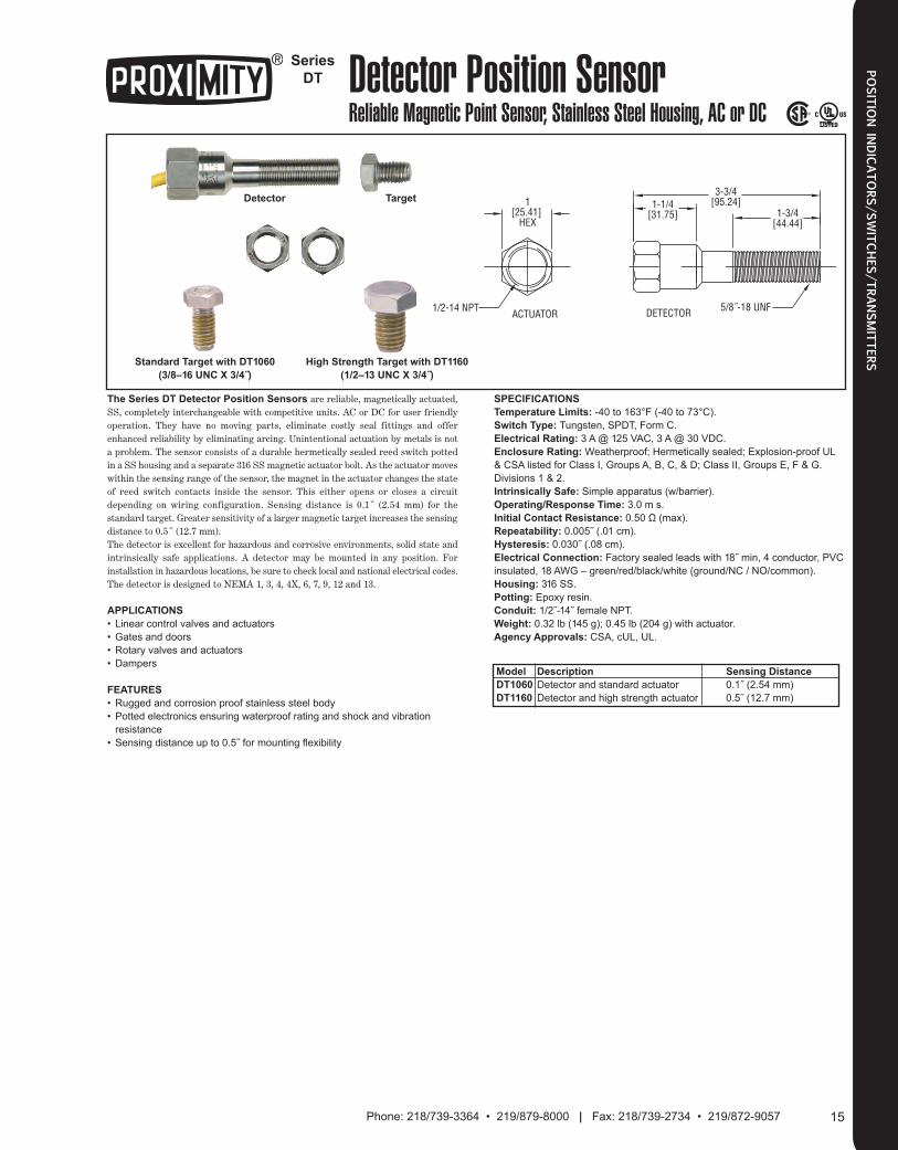
DT Detector Position SensorReliable Magnetic Point Sensor, Stainless Steel Housing, AC or DC
1[25.41]
HEX
1/2-14 NPT ACTUATOR DETECTOR 5/8˝-18 UNF
1-1/4[31.75]
3-3/4[95.24]
1-3/4[44.44]
Detector Target
Standard Target with DT1060 High Strength Target with DT1160
(3/8–16 UNC X 3/4˝) (1/2–13 UNC X 3/4˝)
The Series DT Detector Position Sensors are reliable, magnetically actuated,SS, completely interchangeable with competitive units. AC or DC for user friendlyoperation. They have no moving parts, eliminate costly seal fittings and offerenhanced reliability by eliminating arcing. Unintentional actuation by metals is nota problem. The sensor consists of a durable hermetically sealed reed switch pottedin a SS housing and a separate 316 SS magnetic actuator bolt. As the actuator moveswithin the sensing range of the sensor, the magnet in the actuator changes the stateof reed switch contacts inside the sensor. This either opens or closes a circuitdepending on wiring configuration. Sensing distance is 0.1˝ (2.54 mm) for thestandard target. Greater sensi tivity of a larger magnetic target increases the sensing distance to 0.5˝ (12.7 mm).The detector is excellent for hazardous and corrosive environments, solid state andintrinsically safe applications. A detector may be mounted in any position. Forinstallation in hazardous locations, be sure to check local and national electrical codes.The detector is designed to NEMA 1, 3, 4, 4X, 6, 7, 9, 12 and 13.
APPLICATIONS
• Linear control valves and actuators
• Gates and doors
• Rotary valves and actuators
• Dampers
FEATURES
• Rugged and corrosion proof stainless steel body
• Potted electronics ensuring waterproof rating and shock and vibration
resistance
• Sensing distance up to 0.5˝ for mounting flexibility
SPECIFICATIONS
Temperature Limits: -40 to 163°F (-40 to 73°C).
Switch Type: Tungsten, SPDT, Form C.
Electrical Rating: 3 A @ 125 VAC, 3 A @ 30 VDC.
Enclosure Rating: Weatherproof; Hermetically sealed; Explosion-proof UL
& CSA listed for Class I, Groups A, B, C, & D; Class II, Groups E, F & G.
Divisions 1 & 2.
Intrinsically Safe: Simple apparatus (w/barrier).
Operating/Response Time: 3.0 m s.
Initial Contact Resistance: 0.50 Ω (max).
Repeatability: 0.005˝ (.01 cm).
Hysteresis: 0.030˝ (.08 cm).
Electrical Connection: Factory sealed leads with 18˝ min, 4 conductor, PVC
insulated, 18 AWG – green/red/black/white (ground/NC / NO/common).
Housing: 316 SS.
Potting: Epoxy resin.
Conduit: 1/2˝-14˝ female NPT.
Weight: 0.32 lb (145 g); 0.45 lb (204 g) with actuator.
Agency Approvals: CSA, cUL, UL.
Model
DT1060
DT1160
Description
Detector and standard actuator
Detector and high strength actuator
Sensing Distance
0.1˝ (2.54 mm)
0.5˝ (12.7 mm)
015_Layout 2 1/7/14 1:20 PM Page 1
PROXIMITY CONTROLS, A Division of Dwyer Instruments, Inc. | 1431 State Hwy 210 E, Fergus Falls, MN 5653716
POSITIO
N INDICATORS/SWITCHES/TRANSMITTERS
Series
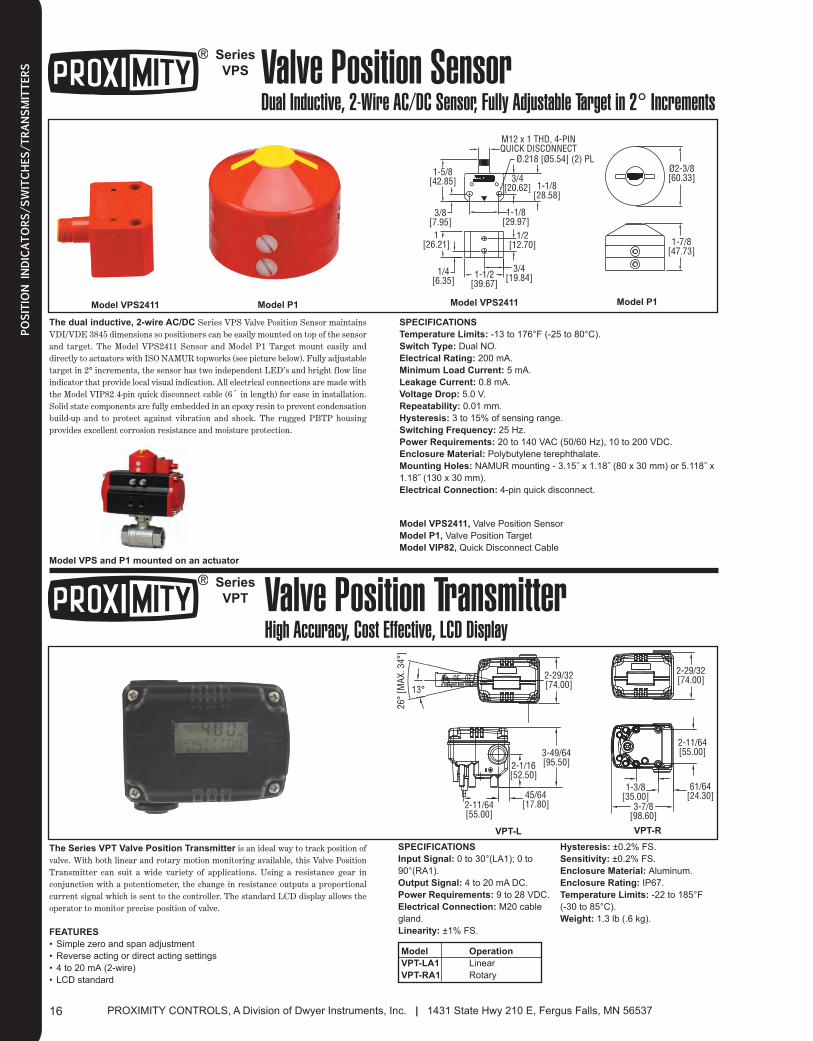
VPS Valve Position SensorDual Inductive, 2-Wire AC/DC Sensor, Fully Adjustable Target in 2° Increments
1-5/8[42.85]
3/8[7.95]
1[26.21]
1/4[6.35]
1-1/2[39.67]
3/4[19.84]
1/2[12.70]
1-1/8[29.97]
1-1/8[28.58]
3/4[20.62]
M12 x 1 THD, 4-PINQUICK DISCONNECT
Ø.218 [Ø5.54] (2) PLØ2-3/8[60.33]
1-7/8[47.73]
Model P1Model VPS2411 Model P1Model VPS2411
The dual inductive, 2-wire AC/DC Series VPS Valve Position Sensor maintainsVDI/VDE 3845 dimensions so positioners can be easily mounted on top of the sensorand target. The Model VPS2411 Sensor and Model P1 Target mount easily anddirectly to actuators with ISO NAMUR topworks (see picture below). Fully adjustabletarget in 2° increments, the sensor has two independent LED’s and bright flow lineindicator that provide local visual indication. All electrical connections are made withthe Model VIP82 4-pin quick disconnect cable (6´ in length) for ease in installation.Solid state components are fully embedded in an epoxy resin to prevent condensationbuild-up and to protect against vibration and shock. The rugged PBTP housingprovides excellent corrosion resistance and moisture protection.
SPECIFICATIONS
Temperature Limits: -13 to 176°F (-25 to 80°C).
Switch Type: Dual NO.
Electrical Rating: 200 mA.
Minimum Load Current: 5 mA.
Leakage Current: 0.8 mA.
Voltage Drop: 5.0 V.
Repeatability: 0.01 mm.
Hysteresis: 3 to 15% of sensing range.
Switching Frequency: 25 Hz.
Power Requirements: 20 to 140 VAC (50/60 Hz), 10 to 200 VDC.
Enclosure Material: Polybutylene terephthalate.
Mounting Holes: NAMUR mounting - 3.15˝ x 1.18˝ (80 x 30 mm) or 5.118˝ x
1.18˝ (130 x 30 mm).
Electrical Connection: 4-pin quick disconnect.
Series
VPT Valve Position TransmitterHigh Accuracy, Cost Effective, LCD Display
2040 30 2-29/32[74.00]
2-11/64[55.00]
45/64[17.80]
2-1/16[52.50]
3-49/64[95.50]
3-7/8[98.60]
1-3/8[35.00]
61/64[24.30]
2-11/64[55.00]
26°
[MAX
. 34°
]
13°2-29/32[74.00]
The Series VPT Valve Position Transmitter is an ideal way to track position ofvalve. With both linear and rotary motion monitoring available, this Valve PositionTransmitter can suit a wide variety of applications. Using a resistance gear inconjunction with a potentiometer, the change in resistance outputs a proportionalcurrent signal which is sent to the controller. The standard LCD display allows theoperator to monitor precise position of valve.
FEATURES
• Simple zero and span adjustment
• Reverse acting or direct acting settings
• 4 to 20 mA (2-wire)
• LCD standard
SPECIFICATIONS
Input Signal: 0 to 30°(LA1); 0 to
90°(RA1).
Output Signal: 4 to 20 mA DC.
Power Requirements: 9 to 28 VDC.
Electrical Connection: M20 cable
gland.
Linearity: ±1% FS.
Hysteresis: ±0.2% FS.
Sensitivity: ±0.2% FS.
Enclosure Material: Aluminum.
Enclosure Rating: IP67.
Temperature Limits: -22 to 185°F
(-30 to 85°C).
Weight: 1.3 lb (.6 kg).
Model
VPT-LA1
VPT-RA1
Model VPS and P1 mounted on an actuator
VPT-RVPT-L
Model VPS2411, Valve Position Sensor
Model P1, Valve Position Target
Model VIP82, Quick Disconnect Cable
Operation
Linear
Rotary
016_Layout 2 1/7/14 1:22 PM Page 1
SERIES 165, PRECISOR® II PNEUMATIC AND ELECTRO-PNEUMATIC POSITIONER . . . . . . . . . . . . . . . . . . . . . . . . . . . .18
SERIES 265, PRECISOR® II PNEUMATIC AND ELECTRO-PNEUMATIC POSITIONER . . . . . . . . . . . . . . . . . . . . . . . . . . . .19
SERIES 275, PRECISOR® III ELECTRO-PNEUMATIC POSITIONERS . . . . . . . . . . . . . . . . . . . . . . . . . . . . . . . . . . . . . . . . . .20
SERIES 185, LINEAR SMART POSITIONER . . . . . . . . . . . . . . . . . . . . . . . . . . . . . . . . . . . . . . . . . . . . . . . . . . . . . . . . . . . . . .21
SERIES 285, ROTARY SMART POSITIONER . . . . . . . . . . . . . . . . . . . . . . . . . . . . . . . . . . . . . . . . . . . . . . . . . . . . . . . . . . . . .22
SERIES 195, COMPACT LINEAR SMART POSITIONER . . . . . . . . . . . . . . . . . . . . . . . . . . . . . . . . . . . . . . . . . . . . . . . . . . . . .23
SERIES 295, COMPACT ROTARY SMART POSITIONER . . . . . . . . . . . . . . . . . . . . . . . . . . . . . . . . . . . . . . . . . . . . . . . . . . . .24
SERIES IP, CURRENT TO PRESSURE TRANSDUCER . . . . . . . . . . . . . . . . . . . . . . . . . . . . . . . . . . . . . . . . . . . . . . . . . . . . .25
SERIES 2700 & 2800, CURRENT TO PRESSURE TRANSDUCER . . . . . . . . . . . . . . . . . . . . . . . . . . . . . . . . . . . . . . . . . . . .26
SERIES 2900, CURRENT TO PRESSURE TRANSDUCER . . . . . . . . . . . . . . . . . . . . . . . . . . . . . . . . . . . . . . . . . . . . . . . . . . .27
17Phone: 218/739-3364 • 219/879-8000 | Fax: 218/739-2734 • 219/872-9057
017_Layout 2 1/7/14 1:23 PM Page 1
Series
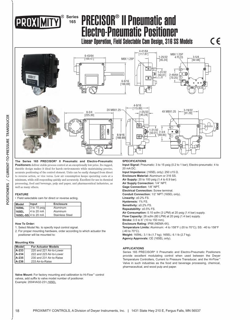
165 PRECISOR® II Pneumatic and Electro-Pneumatic PositionerLinear Operation, Field Selectable Cam Design, 316 SS Models
3-5/8[92.08]
M8X 1.25P4 PLCS
2-49/64[70.25]
1-31/32[50.01]
4-41/64[117.87]
1-25/32[45.24]M8X 1.25P
6-9/16[166.69]
6-43/64[169.47]
OUT2
SUP.
Electro-Pneumatic
POSITIONER
8-3/4[225.30]
2X M8X1.25
4-9/16[115.89]
6-9/16[166.69]
1-25/32[45.24]
3-19/32[91.29]
1-31/32[50.01] 2-3/4
[69.85]
4X M8X1.25
The Series 165 PRECISOR® II Pneumatic and Electro-Pneumatic
Positioners deliver stable process control at an exceptionally low price. Its rugged,durable design makes it ideal for harsh environments while maintaining precise,accurate positioning of the control element. Units can be easily changed from directto reverse action, or vice versa. Low air consumption keeps operating costs at aminimum, while still responding quickly and accurately. Excellent for use in chemicalprocessing, food and beverage, pulp and paper, and pharmaceutical industries, aswell as many others.
FEATURE
• Field selectable cam for direct or reverse acting.
SPECIFICATIONS
Input Signal: Pneumatic: 3 to 15 psig (0.2 to 1 bar); Electro-pneumatic: 4 to
20 mA DC.
Input Impedance: (165EL only): 250 ±15 Ω.
Enclosure Material: Aluminum or 316 SS.
Air Supply: 20 to 100 psig (1.4 to 6.9 bar).
Air Supply Connection: 1/4˝ NPT.
Gage Connection: 1/8˝ NPT.
Electrical Connection: Screw terminal.
Conduit Connection: 1/2˝ NPT (165EL only).
Linearity: ±0.2% FS.
Hysteresis: 1% FS.
Sensitivity: ±0.2% FS.
Repeatability: ±0.5% FS.
Air Consumption: 0.10 scfm (3 LPM) at 20 psig (1.4 bar) supply.
Flow Capacity: 28 scfm (80 LPM) at 20 psig (1.4 bar) supply.
Stroke: 0.5 to 6˝ (10 to 150 mm).
Enclosure Rating: IP66 (NEMA 4X).
Temperature Limits: Aluminum: -4 to 158°F (-20 to 70°C); SS: -40 to 158°F
(-40 to 70°C).
Weight: 165NL: 3.1 lb (1.7 kg); 165EL: 6.1 lb (2.7 kg).
Agency Approvals: CE (165EL only).
APPLICATIONS
Series 165 PRECISOR® II Pneumatic and Electro-Pneumatic Positioners
provide excellent modulating control when used between the Dwyer
Temperature Controllers, Current to Pressure Transducer, and the Hi-Flow™
Valve in such industries as the food and beverage processing, chemical,
pharmaceutical, and wood pulp and paper.
How To Order:
1. Select Model No. to specify input control signal.
2. For proper mounting hardware, order according to which actuator the
positioner will be mounted to:
Model
A-233
A-234
A-235
A-236
Mounting Kits
Input
3 to 15 psig
4 to 20 mA
4 to 20 mA
Model
165NL
165EL
165EL-SS
PROXIMITY CONTROLS, A Division of Dwyer Instruments, Inc. | 1431 State Hwy 210 E, Fergus Falls, MN 5653718
POSITIO
NERS / CURRENT-TO-PRESSURE TRANSDUCER
Enclosure
Aluminum
Aluminum
Stainless Steel
Valve Mount: For factory mounting and calibration to Hi-Flow™ control
valves, add suffix to valve model number of positioner.
Example: 2004VA32-231-165EL
For Actuator Models
220 and 221 Air-to-Lower
222 and 223 Air-to-Lower
230 and 231 Air-to-Raise
233 Air-to-Raise
018_Layout 2 1/7/14 1:24 PM Page 1
Series
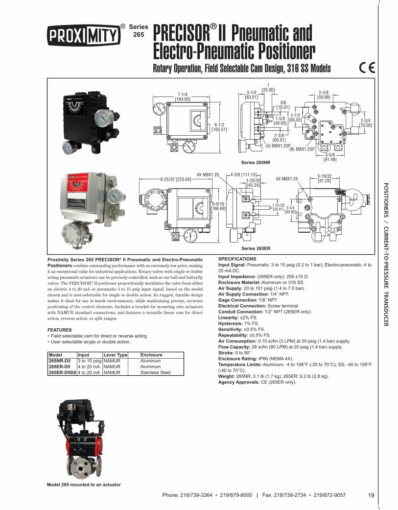
265 PRECISOR® II Pneumatic and Electro-Pneumatic PositionerRotary Operation, Field Selectable Cam Design, 316 SS Models
7-1/4[184.00]
3-1/4[83.01]
1[25.00]
3/8[10.01]
1-5/8[40.00]
2-1/2[65.02]
2-3/8[59.99]
2-3/4[70.00]
3-5/8[91.49]
(8) M8X1.25P(4) M8X1.25P
2-3/8[60.01]
6-1/2[165.51]
Series 265NR
Series 265ER
SUP.
OUT2
8-25/32 [223.04]4-3/8 [111.13]
1-25/32[45.24]
3-19/32[91.29]
1-31/32[50.01] 2-3/4
[69.85]
6-9/16[166.69]
4X M8X1.254X M8X1.25
SPECIFICATIONS
Input Signal: Pneumatic: 3 to 15 psig (0.2 to 1 bar); Electro-pneumatic: 4 to
20 mA DC.
Input Impedance: (265ER only): 250 ±15 Ω.
Enclosure Material: Aluminum or 316 SS.
Air Supply: 20 to 101 psig (1.4 to 7.0 bar).
Air Supply Connection: 1/4˝ NPT.
Gage Connection: 1/8˝ NPT.
Electrical Connection: Screw terminal.
Conduit Connection: 1/2˝ NPT (265ER only).
Linearity: ±2% FS.
Hysteresis: 1% FS.
Sensitivity: ±0.5% FS.
Repeatability: ±0.5% FS.
Air Consumption: 0.10 scfm (3 LPM) at 20 psig (1.4 bar) supply.
Flow Capacity: 28 scfm (80 LPM) at 20 psig (1.4 bar) supply.
Stroke: 0 to 90°.
Enclosure Rating: IP66 (NEMA 4X).
Temperature Limits: Aluminum: -4 to 158°F (-20 to 70°C); SS: -40 to 158°F
(-40 to 70°C).
Weight: 265NR: 3.1 lb (1.7 kg); 265ER: 6.2 lb (2.8 kg).
Agency Approvals: CE (265ER only).
Proximity Series 265 PRECISOR® II Pneumatic and Electro-Pneumatic
Positioners combine outstanding performance with an extremely low price, makingit an exceptional value for industrial applications. Rotary valves with single or doubleacting pneumatic actuators can be precisely controlled, such as our ball and butterflyvalves. The PRECISOR® II positioner proportionally modulates the valve from eitheran electric 4 to 20 mA or pneumatic 3 to 15 psig input signal, based on the modelchosen and is user-selectable for single or double action. Its rugged, durable designmakes it ideal for use in harsh environments, while maintaining precise, accuratepositioning of the control elements. Includes a bracket for mounting onto actuatorswith NAMUR standard connections, and features a versatile linear cam for directaction, reverse action, or split ranges.
FEATURES
• Field selectable cam for direct or reverse acting
• User selectable single or double action.
Model
265NR-D5
265ER-D5
265ER-D5SS
Input
3 to 15 psig
4 to 20 mA
4 to 20 mA
Lever Type
NAMUR
NAMUR
NAMUR
Model 265 mounted to an actuator
19Phone: 218/739-3364 • 219/879-8000 | Fax: 218/739-2734 • 219/872-9057
POSITIO
NERS / CURRENT-TO-PRESSURE TRANSDUCER
Enclosure
Aluminum
Aluminum
Stainless Steel
019_Layout 2 1/7/14 1:24 PM Page 1
Series
275 PRECISOR® III Electro-PneumaticPositionerLow Cost, Rotary Operation, Selectable Single or Double Action
6-13/64[157.56]
3-17/32[89.69]
21/64[8.33]
5-11/32[135.73]
CONDUIT1/2˝
NPT 1/4˝SUPPLY
6-7/64 [155.18]
31/64[12/30]
3/8[9.53]
13/64[5.16]
1-25/32[45.24]
2-11/32[59.53]
1-25/32[45.24]
1-21/32[42.07]
1-25/32[45.24]
2-49/64[70.25]
NPT 1/4˝OUT 2
NPT 1/4˝OUT 1
2-3/8[60.33]
MOUNTING BRACKETS
6-31/64[164.70]
3-35/64[90.09]
6-17/32[165.89]
3-35/64[90.09]
4-5/64[103.58]
4-5/8[117.48]
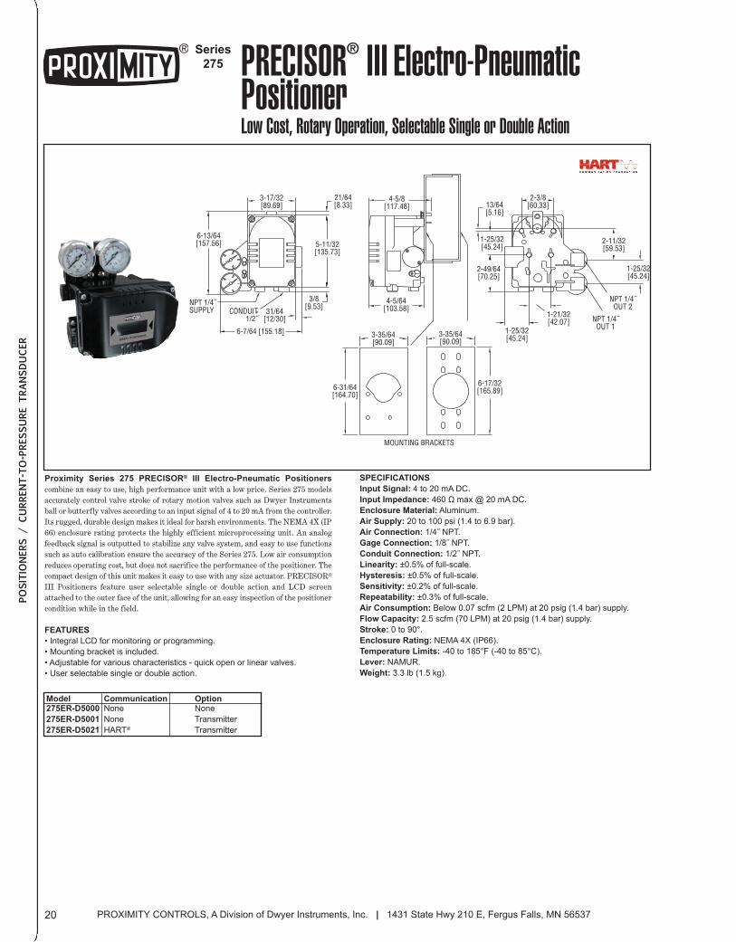
Proximity Series 275 PRECISOR® III Electro-Pneumatic Positioners
combine an easy to use, high performance unit with a low price. Series 275 modelsaccurately control valve stroke of rotary motion valves such as Dwyer Instrumentsball or butterfly valves according to an input signal of 4 to 20 mA from the controller.Its rugged, durable design makes it ideal for harsh environments. The NEMA 4X (IP66) enclosure rating protects the highly efficient microprocessing unit. An analogfeedback signal is outputted to stabilize any valve system, and easy to use functionssuch as auto calibration ensure the accuracy of the Series 275. Low air consumptionreduces operating cost, but does not sacrifice the performance of the positioner. Thecompact design of this unit makes it easy to use with any size actuator. PRECISOR®
III Positioners feature user selectable single or double action and LCD screenattached to the outer face of the unit, allowing for an easy inspection of the positionercondition while in the field.
FEATURES
• Integral LCD for monitoring or programming.
• Mounting bracket is included.
• Adjustable for various characteristics - quick open or linear valves.
• User selectable single or double action.
SPECIFICATIONS
Input Signal: 4 to 20 mA DC.
Input Impedance: 460 Ω max @ 20 mA DC.
Enclosure Material: Aluminum.
Air Supply: 20 to 100 psi (1.4 to 6.9 bar).
Air Connection: 1/4˝ NPT.
Gage Connection: 1/8˝ NPT.
Conduit Connection: 1/2˝ NPT.
Linearity: ±0.5% of full-scale.
Hysteresis: ±0.5% of full-scale.
Sensitivity: ±0.2% of full-scale.
Repeatability: ±0.3% of full-scale.
Air Consumption: Below 0.07 scfm (2 LPM) at 20 psig (1.4 bar) supply.
Flow Capacity: 2.5 scfm (70 LPM) at 20 psig (1.4 bar) supply.
Stroke: 0 to 90°.
Enclosure Rating: NEMA 4X (IP66).
Temperature Limits: -40 to 185°F (-40 to 85°C).
Lever: NAMUR.
Weight: 3.3 lb (1.5 kg).
CommunicationNone
None
HART®
Model275ER-D5000
275ER-D5001
275ER-D5021
PROXIMITY CONTROLS, A Division of Dwyer Instruments, Inc. | 1431 State Hwy 210 E, Fergus Falls, MN 5653720
POSITIO
NERS / CURRENT-TO-PRESSURE TRANSDUCER
OptionNone
Transmitter
Transmitter
020_Layout 2 1/7/14 1:25 PM Page 1
Series
185 Linear Smart PositionerFail Freeze, Linear Operation, HART Communication
3-27/32[97.50]
3-1/64[76.50]
2-11/32[59.60]
CONDUIT ENTRY1/2 NPT
4-7/64[104.20]
2-33/64[64.00] SUPPLY
1/4 NPT
4-13/32[111.90]
STAINLESS STEEL4-31/64[113.8]
STANDARD
8-31/64[215.70]
LCD SCREEN
SMART POSITIONER
3-47/64[95.00]
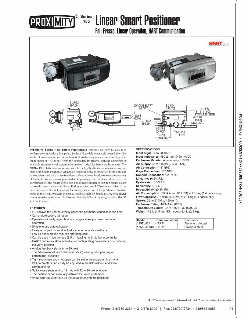
Proximity Series 185 Smart Positioners combine an easy to use, highperformance unit with a low price. Series 185 models accurately control the valvestroke of linear motion valves, such as W.E. Anderson globe valves, according to aninput signal of 4 to 20 mA from the controller. Its rugged, durable aluminum oravailable stainless steel construction makes it ideal for harsh environments. TheNEMA 4X (IP66) enclosure rating protects the highly efficient microprocessing unitinside the Smart Positioner. An analog feedback signal is outputted to stabilize anyvalve system, and easy to use functions such as auto calibration ensure the accuracyof the unit. Low air consumption reduces operating cost, but does not sacrifice theperformance of the Smart Positioner. The compact design of this unit makes it easyto use with any size actuator. Smart Positioners feature a LCD screen attached to theouter surface of the unit, allowing for an easy inspection of the positioner conditionwhile in the field. Available in user selectable single or double action, with HARTcommunication as standard. In the event that the 4-20 mA input signal is lost the 185will fail in place.
FEATURES
• LCD allows the user to directly check the positioner condition in the field
• Can endure severe vibration
• Operates normally regardless of changes in supply pressure during
operation
• Simple to use auto calibration
• Easily equipped on small actuators because of its small size
• Low air consumption reduces operating cost
• Can be used in low voltage (8.5 V), leaving no limitation in controller
• HART® communication available for configurating parameters or monitoring
the valve position
• Analog feedback signal (4 to 20 mA)
• The adjustment of valve characteristics (linear, quick open, equal
percentage) available
• Tight shut-close and shut-open can be set in the programming menu
• PID parameters can easily be adjusted in the field without additional
communicator
• Split ranges such as 4 to 12 mA, with 12 to 20 mA available
• The positioner can manually activate the valve or damper
• An air filter regulator can be mounted directly to the positioner
SPECIFICATIONS
Input Signal: 4 to 20 mA DC.
Input Impedance: 460 Ω max @ 20 mA DC.
Enclosure Material: Aluminum or 316 SS.
Air Supply: 35 to 116 psi (2.4 to 8 bar).
Air Connection: 1/4˝ NPT.
Gage Connection: 1/8˝ NPT.
Conduit Connection: 1/2˝ NPT.
Linearity: ±0.5% FS.
Hysteresis: ±0.5% FS.
Sensitivity: ±0.2% FS.
Repeatability: ±0.3% FS.
Air Consumption: .0004 scfm (.01 LPM) at 20 psig (1.4 bar) supply.
Flow Capacity: 2.1 scfm (60 LPM) at 20 psig (1.4 bar) supply.
Stroke: 0.5 to 6˝ (10 to 150 mm).
Enclosure Rating: NEMA 4X (IP66).
Temperature Limits: -22 to 185°F (-30 to 85°C).
Weight: 3.3 lb (1.5 kg); SS models: 6.4 lb (2.9 kg).
CommunicationHART®
HART®
Model185EL-D1
185EL-D1SS
HART® is a registered trademark of Hart Communication Foundation.
21Phone: 218/739-3364 • 219/879-8000 | Fax: 218/739-2734 • 219/872-9057
POSITIO
NERS / CURRENT-TO-PRESSURE TRANSDUCER
EnclosureAluminum diecast
Stainless steel
021_Layout 2 1/7/14 1:25 PM Page 1
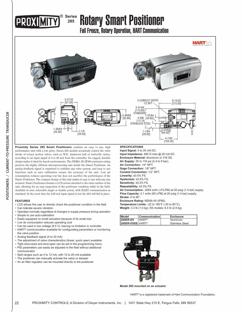
Proximity Series 285 Smart Positioners combine an easy to use, highperformance unit with a low price. Series 285 models accurately control the valvestroke of rotary motion valves, such as W.E. Anderson ball or butterfly valves,according to an input signal of 4 to 20 mA from the controller. Its rugged, durabledesign makes it ideal for harsh environments. The NEMA 4X (IP66) enclosure ratingprotects the highly efficient microprocessing unit inside the Smart Positioner. Ananalog feedback signal is outputted to stabilize any valve system, and easy to usefunctions such as auto calibration ensure the accuracy of the unit. Low airconsumption reduces operating cost but does not sacrifice the performance of theSmart Positioner. The compact design of this unit makes it easy to use with any sizeactuator. Smart Positioners feature a LCD screen attached to the outer surface of theunit, allowing for an easy inspection of the positioner condition while in the field.Available in user selectable single or double action, with HART communication asstandard. In the event that the 4-20 mA input signal is lost the 285 will fail in place.
FEATURES
• LCD allows the user to directly check the positioner condition in the field
• Can tolerate severe vibration
• Operates normally regardless of changes in supply pressure during operation
• Simple to use auto-calibration
• Easily equipped on small actuators because of its small size
• Low air consumption reduces operating cost
• Can be used in low voltage (8.5 V), leaving no limitation in controller
• HART® communication available for configurating parameters or monitoring
the valve position
• Analog feedback signal (4 to 20 mA)
• The adjustment of valve characteristics (linear, quick open) available
• Tight shut-close and shut-open can be set in the programming menu
• PID parameters can easily be adjusted in the field without additional
communicator
• Split ranges such as 4 to 12 mA, with 12 to 20 mA available
• The positioner can manually activate the valve or damper
• An air filter regulator can be mounted directly to the positioner
SPECIFICATIONS
Input Signal: 4 to 20 mA DC.
Input Impedance: 460 Ω max @ 20 mA DC.
Enclosure Material: Aluminum or 316 SS.
Air Supply: 35 to 116 psi (2.4 to 9 bar).
Air Connection: 1/4˝ NPT.
Gage Connection: 1/8˝ NPT.
Conduit Connection: 1/2˝ NPT.
Linearity: ±0.5% FS.
Hysteresis: ±0.5% FS.
Sensitivity: ±0.2% FS.
Repeatability: ±0.3% FS.
Air Consumption: .0004 scfm (.01LPM) at 20 psig (1.4 bar) supply.
Flow Capacity: 2.1 scfm (60 LPM) at 20 psig (1.4 bar) supply.
Stroke: 0 to 90°.
Enclosure Rating: NEMA 4X (IP66).
Temperature Limits: -22 to 185°F (-30 to 85°C).
Weight: 3.3 lb (1.5 kg); SS models: 6.4 lb (2.9 kg).
CommunicationHART®
HART®
Model285ER-D5
285ER-D5SS
HART® is a registered trademark of Hart Communication Foundation.
Series
285 Rotary Smart PositionerFail Freeze, Rotary Operation, HART Communication
LCD SCREEN
SMART POSITIONER
3-49/64[95.80]
8-15/32[215.00]
4-31/64[113.80]
STANDARD
4.406[111.9]
STAINLESS STEEL
1-1/8[28.50]
1-49/64[45.00]
3-27/32[97.50]
4-7/64[104.20]
2-33/64[64.00]1-7/64
[28.00]
1-23/64[34.60]
2-CONDUIT ENTRY1/2 NPT
Model 285 mounted on an actuator
PROXIMITY CONTROLS, A Division of Dwyer Instruments, Inc. | 1431 State Hwy 210 E, Fergus Falls, MN 5653722
POSITIO
NERS / CURRENT-TO-PRESSURE TRANSDUCER
EnclosureAluminum
Stainless Steel
022_Layout 2 1/7/14 1:26 PM Page 1
Series
195 Compact Linear Smart PositionerLow Cost, Linear Operation, HART Communication
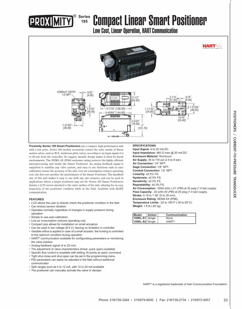
Proximity Series 195 Smart Positioners are a compact, high performance unitwith a low price. Series 195 models accurately control the valve stroke of linearmotion valves, such as W.E. Anderson globe valves, according to an input signal of 4to 20 mA from the controller. Its rugged, durable design makes it ideal for harshenvironments. The NEMA 4X (IP66) enclosure rating protects the highly efficientmicroprocessing unit inside the Smart Positioner. An analog feedback signal isoutputted to stabilize any valve system, and easy to use functions such as autocalibration ensure the accuracy of the unit. Low air consumption reduces operatingcost, but does not sacrifice the performance of the Smart Positioner. The handheldsize of this unit makes it easy to use with any size actuator, and can be used inapplications where a larger positioner may not fit. Series 195 Smart Positionersfeature a LCD screen attached to the outer surface of the unit, allowing for an easyinspection of the positioner condition while in the field. Available with HARTcommunication.
FEATURES
• LCD allows the user to directly check the positioner condition in the field
• Can endure severe vibration
• Operates normally regardless of changes in supply pressure during
operation
• Simple to use auto-calibration
• Low air consumption reduces operating cost
• Compact size allows for installation on small actuators
• Can be used in low voltage (8.5 V), leaving no limitation in controller
• Variable orifice is applied in case of a small actuator, the hunting is controlled
to the optimum condition during operation
• HART® communication available for configurating parameters or monitoring
the valve position
• Analog feedback signal (4 to 20 mA)
• The adjustment of valve characteristics (linear, quick open) available
• Specific flow control is available with setting 16 points at users’ command
• Tight shut-close and shut-open can be set in the programming menu
• PID parameters can easily be adjusted in the field without additional
communicator
• Split ranges such as 4 to 12 mA, with 12 to 20 mA available
• The positioner can manually activate the valve or damper
SPECIFICATIONS
Input Signal: 4 to 20 mA DC.
Input Impedance: 460 Ω max @ 20 mA DC.
Enclosure Material: Aluminum.
Air Supply: 35 to 116 psi (2.4 to 8 bar).
Air Connection: 1/4˝ NPT.
Gage Connection: 1/8˝ NPT.
Conduit Connection: 1/2˝ NPT.
Linearity: ±0.5% FS.
Hysteresis: ±0.5% FS.
Sensitivity: ±0.2% FS.
Repeatability: ±0.3% FS.
Air Consumption: .0004 scfm (.01 LPM) at 20 psig (1.4 bar) supply.
Flow Capacity: .32 scfm (9 LPM) at 20 psig (1.4 bar) supply.
Stroke: 0.19 to 1.38˝ (5 to 35 mm).
Enclosure Rating: NEMA 4X (IP66).
Temperature Limits: -22 to 185°F (-30 to 85°C).
Weight: 1.8 lb (.82 kg).
HART® is a registered trademark of Hart Communication Foundation.
LCD SCREEN SMART POSITIONER 2-1/2˝[63.60]
5-7/16˝ [138.30]5-45/64˝ [144.80]
3-3/32˝[78.50] 4˝
[101.70]
30 102040
5/16˝[8.00]
1-57/64˝[48.00]
15/16˝[24.00]
1-11/32˝[34.00]
2-1/4˝[57.00]
1-27/64˝[36.00]
1-3/16˝[30.00]
CONDUIT ENTRY1/2 NPT
5/32˝[4.00]
Model195EL-S1
195EL-S2
ActionSingle
Single
23Phone: 218/739-3364 • 219/879-8000 | Fax: 218/739-2734 • 219/872-9057
POSITIO
NERS / CURRENT-TO-PRESSURE TRANSDUCER
CommunicationNone
HART®
023_Layout 2 1/7/14 1:26 PM Page 1
HART® is a registered trademark of Hart Communication Foundation.
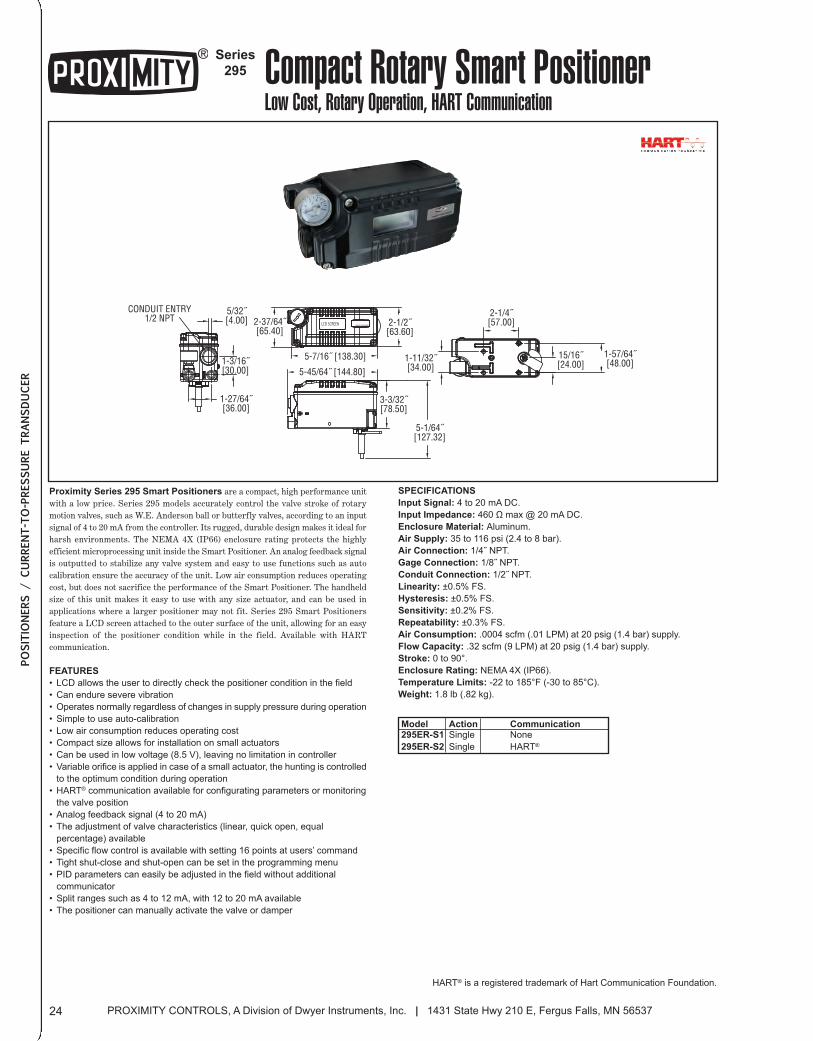
Series
295 Compact Rotary Smart PositionerLow Cost, Rotary Operation, HART Communication
SMART POSITIONERLCD SCREEN 2-1/2˝[63.60]
5-7/16˝ [138.30]
2-37/64˝[65.40]
CONDUIT ENTRY1/2 NPT
5/32˝[4.00]
1-3/16˝[30.00]
1-27/64˝[36.00]
1-11/32˝[34.00]
2-1/4˝[57.00]
1-57/64˝[48.00]
15/16˝[24.00]
5-45/64˝ [144.80]
5-1/64˝[127.32]
3-3/32˝[78.50]
Proximity Series 295 Smart Positioners are a compact, high performance unitwith a low price. Series 295 models accurately control the valve stroke of rotarymotion valves, such as W.E. Anderson ball or butterfly valves, according to an inputsignal of 4 to 20 mA from the controller. Its rugged, durable design makes it ideal forharsh environments. The NEMA 4X (IP66) enclosure rating protects the highlyefficient microprocessing unit inside the Smart Positioner. An analog feedback signalis outputted to stabilize any valve system and easy to use functions such as autocalibration ensure the accuracy of the unit. Low air consumption reduces operatingcost, but does not sacrifice the performance of the Smart Positioner. The handheldsize of this unit makes it easy to use with any size actuator, and can be used inapplications where a larger positioner may not fit. Series 295 Smart Positionersfeature a LCD screen attached to the outer surface of the unit, allowing for an easyinspection of the positioner condition while in the field. Available with HARTcommunication.
FEATURES
• LCD allows the user to directly check the positioner condition in the field
• Can endure severe vibration
• Operates normally regardless of changes in supply pressure during operation
• Simple to use auto-calibration
• Low air consumption reduces operating cost
• Compact size allows for installation on small actuators
• Can be used in low voltage (8.5 V), leaving no limitation in controller
• Variable orifice is applied in case of a small actuator, the hunting is controlled
to the optimum condition during operation
• HART® communication available for configurating parameters or monitoring
the valve position
• Analog feedback signal (4 to 20 mA)
• The adjustment of valve characteristics (linear, quick open, equal
percentage) available
• Specific flow control is available with setting 16 points at users’ command
• Tight shut-close and shut-open can be set in the programming menu
• PID parameters can easily be adjusted in the field without additional
communicator
• Split ranges such as 4 to 12 mA, with 12 to 20 mA available
• The positioner can manually activate the valve or damper
SPECIFICATIONS
Input Signal: 4 to 20 mA DC.
Input Impedance: 460 Ω max @ 20 mA DC.
Enclosure Material: Aluminum.
Air Supply: 35 to 116 psi (2.4 to 8 bar).
Air Connection: 1/4˝ NPT.
Gage Connection: 1/8˝ NPT.
Conduit Connection: 1/2˝ NPT.
Linearity: ±0.5% FS.
Hysteresis: ±0.5% FS.
Sensitivity: ±0.2% FS.
Repeatability: ±0.3% FS.
Air Consumption: .0004 scfm (.01 LPM) at 20 psig (1.4 bar) supply.
Flow Capacity: .32 scfm (9 LPM) at 20 psig (1.4 bar) supply.
Stroke: 0 to 90°.
Enclosure Rating: NEMA 4X (IP66).
Temperature Limits: -22 to 185°F (-30 to 85°C).
Weight: 1.8 lb (.82 kg).
Model295ER-S1
295ER-S2
ActionSingle
Single
PROXIMITY CONTROLS, A Division of Dwyer Instruments, Inc. | 1431 State Hwy 210 E, Fergus Falls, MN 5653724
POSITIO
NERS / CURRENT-TO-PRESSURE TRANSDUCER
CommunicationNone
HART®
024_Layout 2 1/7/14 1:27 PM Page 1
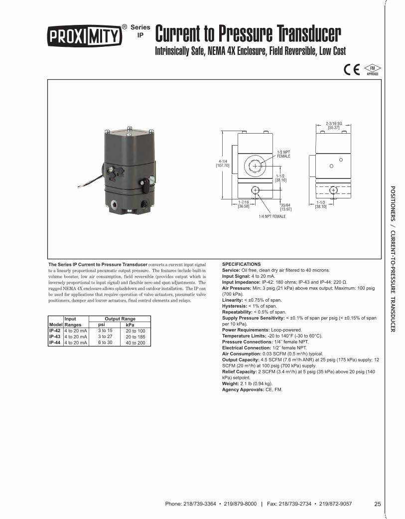
Series
IP Current to Pressure TransducerIntrinsically Safe, NEMA 4X Enclosure, Field Reversible, Low Cost
1/2 NPTFEMALE
1-1/2[38.10]
1/4 NPT FEMALE
35/64[13.97]
4-1/4[107.70]
1-7/16[36.58]
2-3/16 SQ [55.37]
1-1/2[38.10]
The Series IP Current to Pressure Transducer converts a current input signalto a linearly proportional pneumatic output pressure. The features include built-involume booster, low air consumption, field reversible (provides output which isinversely proportional to input signal) and flexible zero and span adjustments. Therugged NEMA 4X enclosure allows splashdown and outdoor installation. The IP canbe used for applications that require operation of valve actuators, pneumatic valvepositioners, damper and louver actuators, final control elements and relays.
SPECIFICATIONS
Service: Oil free, clean dry air filtered to 40 microns.
Input Signal: 4 to 20 mA.
Input Impedance: IP-42: 180 ohms; IP-43 and IP-44: 220 Ω.
Air Pressure: Min: 3 psig (21 kPa) above max output; Maximum: 100 psig
(700 kPa).
Linearity: < ±0.75% of span.
Hysteresis: < 1% of span.
Repeatability: < 0.5% of span.
Supply Pressure Sensitivity: < ±0.1% of span per psig (< ±0.15% of span
per 10 kPa).
Power Requirements: Loop-powered.
Temperature Limits: -20 to 140°F (-30 to 60°C).
Pressure Connections: 1/4˝ female NPT.
Electrical Connection: 1/2˝ female NPT.
Air Consumption: 0.03 SCFM (0.5 m3/h) typical.
Output Capacity: 4.5 SCFM (7.6 m3/h ANR) at 25 psig (175 kPa) supply; 12
SCFM (20 m3/h) at 100 psig (700 kPa) supply.
Relief Capacity: 2 SCFM (3.4 m3/h) at 5 psig (35 kPa) above 20 psig (140
kPa) setpoint.
Weight: 2.1 lb (0.94 kg).
Agency Approvals: CE, FM.
Model
IP-42
IP-43
IP-44
Input
Ranges
4 to 20 mA
4 to 20 mA
4 to 20 mA
25Phone: 218/739-3364 • 219/879-8000 | Fax: 218/739-2734 • 219/872-9057
POSITIO
NERS / CURRENT-TO-PRESSURE TRANSDUCER
psi
3 to 15
3 to 27
6 to 30
Output Range
kPa
20 to 100
20 to 185
40 to 200
025_Layout 2 1/7/14 1:27 PM Page 1
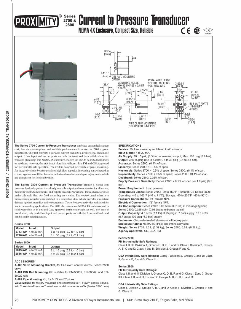
series2700 &2800 Current to Pressure Transducer
NEMA 4X Enclosure, Compact Size, Reliable
39/64[15.5]
1-11/16[42.7]
1[25.4]
ø1/8[ø3.17]
DIN RAIL MOUNTINGOPTION
1-1/2[38.1] 1-19/64
[33.0]
1/2[12.7]
1-51/64[45.7]
PIPE CLAMP MOUNTINGOPTION FOR 1-1/2 PIPE
2-3/16[55.4]
3-11/16[93.7]
5/16[7.92]
MOUNTING HOLES#10-32 UNF-2B x 3/8 DP2 PLCS 2-15/16
[74.7]
22 GA. WIRE LEADSAPPROX. 18˝ LONGPOS, NEG, GRD
49/64[19.4]
33/64[13.1]
3-1/8[79.2]
1-1/2[38.1]
25/64[9.72]
IN & OUT PORTS1/4-18 NPT4 PLCS
ø1-1/8[ø28.7]1/2 NPT
3-23/64[85.3]2-1/4[57/2]
The series 2700 current to Pressure Transducer combines economical startupcost, low air consumption, and reliable performance to make the 2700 a greatinvestment. The unit converts a variable current signal to a proportional pneumaticoutput. It has input and output ports on both the front and back which allows forversatile plumbing. The NEMA 4X enclosure enables the unit to be installed indoorsor outdoors, however, the unit is not vibration resistant. It is FM and CSA approvedfor intrinsically safe operation. The 2700 is designed for remote or panel mounting.An integral volume booster provides high flow capacity, increasing control speed incritical applications. Other features include external zero and span adjustments whichare convenient for field calibration.
The series 2800 current to Pressure Transducer utilizes a closed looppressure feedback system that closely controls output and compensates for vibration,mounting angle, temperature, and supply pressure variations. These characteristicsmake this unit ideal for field mounting on a valve. The control mechanism is apiezoceramic actuator encapsulated in a protective skin, which provides a constantdefense against humidity and contaminants. These features make this unit ideal foruse in demanding applications. The 2800 also comes in a NEMA 4X enclosure and isfield reversible. It is FM and CSA approved intrinsically safe, as well. For ease ofinstallation, this model has input and output ports on both the front and back andcan be easily panel mounted.
sPeciFicATiONs
service: Oil free, clean dry air filtered to 40 microns.
input signal: 4 to 20 mA.
Air supply: Min: 5 psig (0.3 bar) above max output; Max: 100 psig (6.9 bar).
Output: 3 to 15 psig (0.2 to 1.0 bar), 6 to 30 psig (0.4 to 2.1 bar).
Accuracy: Series 2800: ±0.1% of span.
Linearity: Series 2700: < ±0.5% of span.
Hysteresis: Series 2700: < 0.5% of span; Series 2800: ±0.1% of span.
repeatability: Series 2700: < 0.5% of span; Series 2800: ±0.1% of span.
Deadband: Series 2800: 0.02% of span.
supply Pressure sensitivity: Series 2700: < 0.1% of span per 1.0 psig (0.1
bar).
Power requirement: Loop powered.
Temperature Limits: Series 2700: -20 to 150°F (-29 to 66°C); Series 2800:
Operating: -40 to 160°F (-40 to 71°C); Storage: -40 to 200°F (-40 to 93°C).
Pressure connections: 1/4˝ female NPT.
electrical connection: 1/2˝ female NPT.
Air consumption: Series 2700: 0.03 scfm (0.01 l/s) at midrange typical;
Series 2800: 0.025 scfm (0.01 l/s) at midrange typical.
Output capacity: 4.5 scfm (2.1 l/s) at 25 psig (1.7 bar) supply; 12.0 scfm
(5.7 l/s) at 100 psig (6.9 bar) supply.
enclosure: Chromate-treated aluminum with epoxy paint.
enclosure rating: NEMA 4X (IP66) and intrinsically safe.
Weight: Series 2700: 1.3 lb (0.59 kg); Series 2800: 0.8 lb (0.37 kg).
Agency Approvals: CE, CSA, FM.
series 2700
FM intrinsically safe ratings:
Class I, II, III, Division 1, Groups C, D, E, F and G; Class I, Division 2, Groups
A, B, C and D; Class II and III, Division 2, Groups F and G.
csA intrinsically safe ratings: Class I, Division 2, Groups C and D; Class
II, Groups E, F and G; Class III.
series 2800
FM intrinsically safe ratings:
Class I, II, and III, Division 1, Groups C, D, E, F, and G; Class I, Zone 0, Group
IIB; Class I, II, and III, Division 2, Groups A, B, C, D, F, and G.
csA intrinsically safe ratings:
Class I, Division 2, Groups A, B, C and D; Class II, Division 2, Groups F and
G; Class III.
series 2700
series 2800
Model
2713-WP
2716-WP
input
4 to 20 mA
4 to 20 mA
Model
2813-WP
2816-WP
input
4 to 20 mA
4 to 20 mA
PROXIMITY CONTROLS, A Division of Dwyer Instruments, Inc. | 1431 State Hwy 210 E, Fergus Falls, MN 5653726
POSITIO
NERS / CURRENT-TO-PRESSURE TRANSDUCER
AccessOries
A-180 Valve Mounting Bracket, for Hi-FlowTM control valves (Series 2800
only)
A-181 DiN rail Mounting Kit, suitable for EN-50035, EN-50042, and EN-
50022 rails
A-182 Pipe Mounting Kit, for 1-1/2 and 2˝ pipes
Valve Mount, for factory mounting and calibration to Hi-FlowTM control valves,
add Current-to-Pressure Transducer model number as suffix (Series 2800 only)
Output
3 to 15 psig (0.2 to 1.0 bar)
6 to 30 psig (0.4 to 2.1 bar)
Output
3 to 15 psig (0.2 to 1.0 bar)
6 to 30 psig (0.4 to 2.1 bar)
026_Layout 2 1/7/14 1:28 PM Page 1
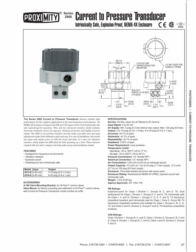
The series 2900 current to Pressure Transducer delivers reliable highperformance for the toughest applications in the most hazardous environments. ItsNEMA 4X housing is designed and FM and CSA approved for both intrinsically safeand explosion-proof operation. This unit has advanced circuitry which includeselectronic feedback control for superior vibration protection and highly accurateoutput. The 2900 is not position sensitive and the easily accessible zero and spanadjustments make field calibration quick and easy. For ease of installation, this modelhas input and output ports on both the front and back. It is also not vibrationsensitive, which makes the 2900 ideal for field mounting on a valve. These featurescoupled with the unit’s compact size help make set-up and installation simple.
FeATUres
• Designed for hazardous environments
• Vibration resistant
• Explosion-proof
• Weatherproof and intrinsically safe
sPeciFicATiONs
service: Oil free, clean dry air filtered to 40 microns.
input signal: 4 to 20 mA.
Air supply: Min: 5 psig (0.3 bar) above max output; Max: 100 psig (6.9 bar).
Output: 3 to 15 psig (0.2 to 1.0 bar), 6 to 30 psig (0.4 to 2.1 bar).
Accuracy: ±0.1% of span.
Hysteresis: ±0.1% of span.
repeatability: ±0.1% of span.
Deadband: 0.02% of span.
Power requirement: Loop powered.
Temperature Limits:
Operating: -40 to 160°F (-40 to 71°C);
Storage: -40 to 200°F (-40 to 93°C).
Pressure connections: 1/4˝ female NPT.
electrical connection: 1/2˝ female NPT.
Air consumption: 0.05 scfm (0.02 l/s) at midrange typical.
Output capacity: 4.5 scfm (2.1 l/s) at 25 psig (1.7 bar) supply; 12.0 scfm
(5.7 l/s) at 100 psig (6.9 bar) supply.
enclosure: Chromate-treated aluminum with epoxy paint.
enclosure rating: Weatherproof NEMA 4X (IP66), explosion-proof and
intrinsically safe.
Weight: 1.8 lb (0.82 kg).
Agency Approvals: CE, CSA, FM.
FM ratings:
Explosion-proof for Class I Division 1, Groups B, C, and D. T6, Dust
Ignitionproof for Class I, Division 1, Groups E, F, and G, T6; Intrinsically safe
for Class I, II, and III, Division 1, Groups C, D, E, F, and G, T4 hazardous
(classified) locations and intrinsically safe for Class I, Zone 0, Group IIB, T4
hazardous (classified) locations and suitable for Class I, Groups A, B, C, D,
T4, and Class II and III, Division 2, Groups F and G, T6 hazardous (classified)
locations.
csA ratings:
Class I Division 1, Groups B, C, and D; Class I, Division 2, Groups A, B, C and
D; Class II, Division 1, Groups E, F, and G; Class II and III, Division 2, Groups
F and G.
Model
2913-e
2916-e
input
4-20 mA
4-20 mA
series2900 Current to Pressure Transducer
Intrinsically Safe, Explosion-Proof, NEMA 4X Enclosure
1/2 NPT PORT FORCONDUIT PIPING
4-19/32[116.6]
2-5/64[52.6]
33/64[13.1]1-1/2
[38.1]
49/64[19.4]
4 #10-32-UNFTAPPED HOLES FORMOUNTING
Ø3-1/2[Ø88.9]
1[25.4]
27/32[21.3]
2-1/2[63.5]
2-3/16[55.6]
57/64[22.4]
IN & OUTPORTS 1/4-18 NPT4 PLACES
27Phone: 218/739-3364 • 219/879-8000 | Fax: 218/739-2734 • 219/872-9057
POSITIO
NERS / CURRENT-TO-PRESSURE TRANSDUCER
AccessOries
A-180 Valve Mounting Bracket, for Hi-FlowTM control valves
Valve Mount, for factory mounting and calibration to Hi-FlowTM control valves,
add Current-to-Pressure Transducer model number as suffix
Output
3-15 psig (0.2-1.0 bar)
6-30 psig (0.4-2.1 bar)
027_Layout 2 1/7/14 1:28 PM Page 1
SERIES VB, VOLUME BOOSTER ...............................................................................................................................29
SERIES AFR2, INSTRUMENT AIR FILTER REGULATOR ..........................................................................................29
SERIES SAFR, SUBMINIATURE AIR PRESSURE REGULATOR ..............................................................................30
SERIES R, REGULATORS...........................................................................................................................................30
SERIES FR, FILTER REGULATORS ...........................................................................................................................31
SERIES SN, NAMUR MOUNT SOLENOID VALVE......................................................................................................32
PROXIMITY CONTROLS, A Division of Dwyer Instruments, Inc. | 1431 State Hwy 210 E, Fergus Falls, MN 5653728
028_Layout 2 1/7/14 1:29 PM Page 1
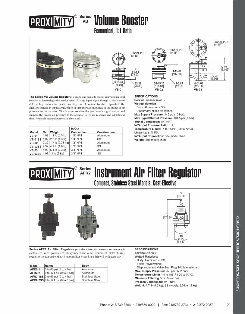
29Phone: 218/739-3364 • 219/879-8000 | Fax: 218/739-2734 • 219/872-9057
REGULATORS/VOLUME BOOSTERS/SOLENOIDS
Series
VB Volume BoosterEconomical, 1:1 Ratio
S I G
SIGNAL PORT1/4 NPT
SIGNAL PORT1/4 NPT
SIGNAL PORT1/4 NPT
6-3/8[162.02]
1-27/32[47.00]
4-51/64[122.00]
3-25/64[86.00] 25/32
[20.00]
3-7/64[79.00]
Ø3-15/16[100.00]
4-15/64[107.50]
1-3/64[26.50]
The Series VB Volume Booster is a one to one signal to output relay and an idealsolution to increasing valve stroke speed. A large input signal change to the boosterdelivers high volume for quick throttling control. Volume booster responds to theslightest changes in input signal, which in turn increases accuracy of the output of airpressure to the actuator. This booster receives the positioner’s signal output andsupplies the proper air pressure to the actuator to reduce response and adjustmenttime. Available in aluminum or stainless steel.
SPECIFICATIONS
Service: Aluminum or SS.
Wetted Materials:
Body: Aluminum or SS;
Diaphragm: Nitrile elastomer.
Max Supply Pressure: 145 psi (10 bar).
Max Signal/Output Pressure: 101.5 psi (7 bar).
Signal Connection: 1/4˝ NPT.
In/Output Pressure Ratio: 1:1.
Temperature Limits: -4 to 158°F (-20 to 70°C).
Linearity: ±1% FS.
In/Output Connection: See model chart.
Weight: See model chart.
Weight1.1 lb (0.5 kg)
2.9 lb (1.3 kg)
1.7 lb (0.76 kg)
4.2 lb (1.9 kg)
5.1 lb (2.3 kg)
11 lb (5 kg)
Model
VB-01
VB-01SS
VB-02
VB-02SS
VB-03
VB-03SS
Cv1.02
1.02
2.32
2.32
4.98
4.98
SeriesAFR2 Instrument Air Filter Regulator
Compact, Stainless Steel Models, Cost-Effective
A DIV OF DWYER INSTRUMENTS, INCMICHIGAN CITY, IN USA
AFR2-XPRESSURE REGULATOR
MAXIMUM SUPPLY 250 PSIGRANGE 0-XX PSIG
7[176.38]
3 [76.20]
2-1/2[63.50]
TM
SPECIFICATIONS
Service: Air only.
Wetted Materials:
Body: Aluminum or SS;
Filter: Polyethylene;
Diaphragm and Valve Seat Plug: Nitrile elastomer.
Max. Supply Pressure: 250 psi (17.2 bar).
Temperature Limits: -4 to 158°F (-20 to 70°C).
Minimum Filtering Size: 5 microns.
Process Connection: 1/4˝ NPT.
Weight: 1.7 lb (0.6 kg), SS models: 3.0 lb (1.4 kg).
Model
AFR2-1
AFR2-2
AFR2-1SS
AFR2-2SS
Range
0 to 60 psi (0 to 4 bar)
0 to 121 psi (0 to 8 bar)
0 to 60 psi (0 to 4 bar)
0 to 121 psi (0 to 8 bar)
Series AFR2 Air Filter Regulator provides clean air pressure to pneumaticcontrollers, valve positioners, air cylinders and other equipment. Self-relievingregulator is equipped with a 40 micron filter housed in a dripwell with gage port.
VB-01 VB-02 VB-03
In/Out
Connection1/4˝ NPT
1/4˝ NPT
1/2˝ NPT
1/2˝ NPT
3/4˝ NPT
3/4˝ NPT
Body
Aluminum
Aluminum
Stainless Steel
Stainless Steel
ConstructionAluminum
SS
Aluminum
SS
Aluminum
SS
029_Layout 2 1/7/14 1:31 PM Page 1
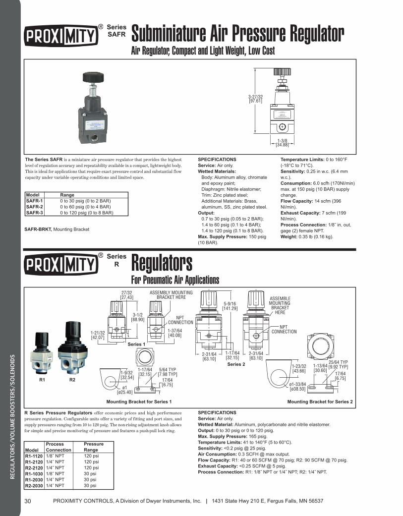
PROXIMITY CONTROLS, A Division of Dwyer Instruments, Inc. | 1431 State Hwy 210 E, Fergus Falls, MN 5653730
REGULATORS/VOLUME BOOSTERS/SOLENOIDS
SeriesSAFR Subminiature Air Pressure Regulator
Air Regulator, Compact and Light Weight, Low Cost
R1 R2
3-1/2[88.90]
27/32[27.43]
1-21/32[42.07]
1-37/64[40.08]
NPT CONNECTION
ASSEMBLY MOUNTINGBRACKET HERE
1
1-13/64[30.60]
25/64 TYP[9.92 TYP]
17/64[6.75]
5
1-23/32[43.66]
ø1-33/84[ø38.50]
1-9/32[32.54]
ø1[ø25.40]
17/64[6.75]
1-17/64[32.15]
5/64 TYP[7.98 TYP]
5-9/16[141.29]
NPT CONNECTION
1-17/64[32.15]
2-31/64[63.10]
2-31/64[63.10]
ASSEMBLEMOUNTING
BRACKETHERE
1
SPECIFICATIONS
Service: Air only.
Wetted Material: Aluminum, polycarbonate and nitrile elastomer.
Output: 0 to 30 psig or 0 to 120 psig.
Max. Supply Pressure: 165 psig.
Temperature Limits: 41 to 140°F (5 to 60°C).
Sensitivity: <0.2 psig @ 25 psig.
Air Consumption: 0.3 SCFH @ max output.
Flow Capacity: R1: 40 or 60 SCFM @ 70 psig; R2: 90 SCFM @ 70 psig.
Exhaust Capacity: <0.25 SCFM @ 5 psig.
Process Connection: R1: 1/8˝ NPT or 1/4˝ NPT; R2: 1/4˝ NPT.
R Series Pressure Regulators offer economic prices and high performancepressure regulation. Configurable units offer a variety of fitting and port sizes, andsupply pressures ranging from 10 to 120 psig. The non-rising adjustment knob allowsfor simple and precise monitoring of pressure and features a push-pull lock ring.
Model
R1-1120
R1-2120
R2-2120
R1-1030
R1-2030
R2-2030
Process
Connection
1/8˝ NPT
1/4˝ NPT
1/4˝ NPT
1/8˝ NPT
1/4˝ NPT
1/4˝ NPT
Series
R RegulatorsFor Pneumatic Air Applications
3-27/32[97.61]
1-3/8[34.88]
(DATE CODE)W.E. ANDERSON
A DIV. OF DWYER INSTRUMENTS, INC.MICHIGAN CITY, IN USA
SAFR-XPRESSURE REGULATOR
0-XX PSIG (MAXIMUM SUPPLY 150 PSIG)
The Series SAFR is a miniature air pressure regulator that provides the highestlevel of regulation accuracy and repeatability available in a compact, lightweight body.This is ideal for applications that require exact pressure control and substantial flowcapacity under variable operating conditions and limited space.
Model
SAFR-1
SAFR-2
SAFR-3
SPECIFICATIONS
Service: Air only.
Wetted Materials:
Body: Aluminum alloy, chromate
and epoxy paint;
Diaphragm: Nitrile elastomer;
Trim: Zinc plated steel;
Additional Materials: Brass,
aluminum, SS, zinc plated steel.
Output:
0.7 to 30 psig (0.05 to 2 BAR);
1.4 to 60 psig (0.1 to 4 BAR);
1.4 to 120 psig (0.1 to 8 BAR).
Max. Supply Pressure: 150 psig
(10 BAR).
Temperature Limits: 0 to 160°F
(-18°C to 71°C).
Sensitivity: 0.25 in w.c. (6.4 mm
w.c.).
Consumption: 6.0 scfh (170NI/min)
max. at 150 psig (10 BAR) supply
change.
Flow Capacity: 14 scfm (396
NI/min).
Exhaust Capacity: 7 scfm (199
NI/min).
Process Connection: 1/8˝ in, out,
gage (2) female NPT.
Weight: 0.35 lb (0.16 kg).
Series 1
Series 2
Mounting Bracket for Series 1 Mounting Bracket for Series 2
Pressure
Range
120 psi
120 psi
120 psi
30 psi
30 psi
30 psi
Range
0 to 30 psig (0 to 2 BAR)
0 to 60 psig (0 to 4 BAR)
0 to 120 psig (0 to 8 BAR)
SAFR-BRKT, Mounting Bracket
030_Layout 2 1/7/14 1:31 PM Page 1

31Phone: 218/739-3364 • 219/879-8000 | Fax: 218/739-2734 • 219/872-9057
REGULATORS/VOLUME BOOSTERS/SOLENOIDS
Series
FR Filter RegulatorsCombination Packages For Pneumatic Air Applications
FR1 FR2
9-7/16[239.71]
SERIES FR2
NPT CONNECTION
3-7/8[98.43]
6-3/8[161.93]
1-37/64[40.08]
SERIES FR1
NPT CONNECTION
MOUNTING BRACKETFOR SERIES FR2
1-13/64[30.60]
17/84[6.75]
ø1-33/64[ø38.50]
1-23/32[43.66]
25/64 TYP[9.92 TYP]
1
MOUNTING BRACKETFOR SERIES FR1
M
1-17/64[32.15]
ø1[ø25.70]
1-9/32[32.54]
6
17/64[6.75]
5/64 TYP[1.98 TYP]
Size 1
Air
41 to 140°F (5 to 60°C)
165 psig
1/8˝, 1/4˝ NPT
5µ, 50µ
165 psi
Manual
0.75 in3
55, 85 SCFM
1/8˝, 1/4˝ NPT
< 0.2 psig
< 0.25 SCFM
40, 60 SCFM
0 to 30 psig
0 to 120 psig
0.3 SCFH
Size 2
Air
41 to 140°F (5 to 60°C)
165 psig
1/4˝ NPT
5µ, 50µ
165 psi
Manual
2.75 in3
120 SCFM
1/4˝ NPT
< 0.2 psig
< 0.25 SCFM
90 SCFM
0 to 30 psig
0 to 120 psig
0.3 SCFH
General
Service
Temperature Limits
Maximum Supply Pressure
Filters
Process Connection
Filtration (micron)
Maximum Supply Pressure
Drain
Bowl Capacity
Flow (based on 100 psi inlet
pressure w/ 50 micron filter)
Construction
Regulators
Process Connection
Effect of Supply Pressure Variation
(25 psig) on Outlet Pressure
Exhaust Capacity (5 psig above 20
psig set point)
Flow Capacity at 100 psig Supply
and 70 psig Outlet
Output Pressure Ranges
Total Air Consumption @
Maximum Output
Construction
Body: Aluminum; Filter: Sintered Bronze
Body: Aluminum; Bowl: Polycarbonate
SPECIFICATIONSThe Series FR Filter-Regulators are combination units that providemaximum options in minimal space. Constructed of aluminum andpolycarbonate, these rugged units offer the same air pressure regulationfeatures as our standard R Series units side-by-side with the convenience ofa filter. Unscrewing the adjustment knob and retaining flange easily adaptspanel or bracket mounting.
Model
FR1-112050M
FR1-212050M
FR1-112005M
FR1-212005M
FR2-212050M
FR2-212005M
FR1-103050M
FR1-203050M
FR1-103005M
FR1-203005M
FR2-203050M
Process
Connection
1/8˝ NPT
1/4˝ NPT
1/8˝ NPT
1/4˝ NPT
1/4˝ NPT
1/4˝ NPT
1/8˝ NPT
1/4˝ NPT
1/8˝ NPT
1/4˝ NPT
1/4˝ NPT
Pressure
Range
120 psi
120 psi
120 psi
120 psi
120 psi
120 psi
30 psi
30 psi
30 psi
30 psi
30 psi
1-1/8̋ NPT 1-1/4̋ NPT 2-1/4̋ NPT
REGULATED PRESSURE VS. FLOW5.5
4.8
4.1
3.4
2.8
2.1
1.4
0.7
0
psig80
70
60
50
40
30
20
10
0
BAR
SCFM 0LPM 0
20.0575
40.01150
60.01700
80.02265
100.02875
120.003450
Filtration
50 microns
50 microns
5 microns
5 microns
50 microns
5 microns
50 microns
50 microns
5 microns
5 microns
50 microns
031_Layout 2 1/7/14 1:32 PM Page 1
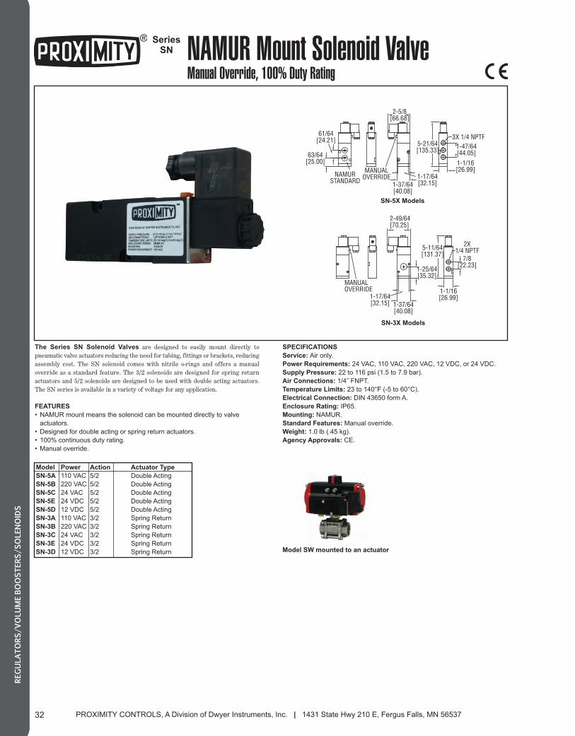
PROXIMITY CONTROLS, A Division of Dwyer Instruments, Inc. | 1431 State Hwy 210 E, Fergus Falls, MN 5653732
REGULATORS/VOLUME BOOSTERS/SOLENOIDS
SeriesSN NAMUR Mount Solenoid Valve
Manual Override, 100% Duty Rating
MANUALOVERRIDE
2-49/64[70.25]
1-17/64[32.15] 1-37/64
[40.08]
1-1/16[26.99]
2X1/4 NPTF
7/8[22.23]
5-11/64[131.37]
1-25/64[35.32]
2-5/8[66.68]
3X 1/4 NPTF1-47/64[44.05]
5-21/64[135.33]
1-1/16[26.99]
63/64[25.00]
61/64[24.21]
NAMURSTANDARD
MANUALOVERRIDE 1-17/64
[32.15]1-37/64[40.08]
The Series SN Solenoid Valves are designed to easily mount directly topneumatic valve actuators reducing the need for tubing, fittings or brackets, reducingassembly cost. The SN solenoid comes with nitrile o-rings and offers a manualoverride as a standard feature. The 3/2 solenoids are designed for spring returnactuators and 5/2 solenoids are designed to be used with double acting actuators.The SN series is available in a variety of voltage for any application.
FEATURES
• NAMUR mount means the solenoid can be mounted directly to valve
actuators.
• Designed for double acting or spring return actuators.
• 100% continuous duty rating.
• Manual override.
SPECIFICATIONS
Service: Air only.
Power Requirements: 24 VAC, 110 VAC, 220 VAC, 12 VDC, or 24 VDC.
Supply Pressure: 22 to 116 psi (1.5 to 7.9 bar).
Air Connections: 1/4˝ FNPT.
Temperature Limits: 23 to 140°F (-5 to 60°C).
Electrical Connection: DIN 43650 form A.
Enclosure Rating: IP65.
Mounting: NAMUR.
Standard Features: Manual override.
Weight: 1.0 lb (.45 kg).
Agency Approvals: CE.
Model
SN-5A
SN-5B
SN-5C
SN-5E
SN-5D
SN-3A
SN-3B
SN-3C
SN-3E
SN-3D
Power
110 VAC
220 VAC
24 VAC
24 VDC
12 VDC
110 VAC
220 VAC
24 VAC
24 VDC
12 VDC
Action
5/2
5/2
5/2
5/2
5/2
3/2
3/2
3/2
3/2
3/2 Model SW mounted to an actuator
SN-3X Models
SN-5X Models
Actuator Type
Double Acting
Double Acting
Double Acting
Double Acting
Double Acting
Spring Return
Spring Return
Spring Return
Spring Return
Spring Return
032_Layout 2 1/7/14 1:33 PM Page 1
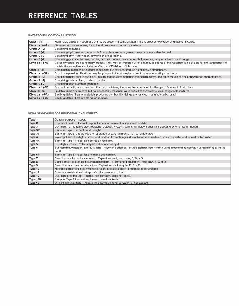
REFERENCE TABLES
HAZARDOUS LOCATIONS LISTINGS
Type 1
Type 2
Type 3
Type 3R
Type 3S
Type 4
Type 4X
Type 5
Type 6
Type 6P
Type 7
Type 8
Type 9
Type 10
Type 11
Type 12
Type 12K
Type 13
Flammable gases or vapors are or may be present in sufficient quantities to produce explosive or ignitable mixtures.
Gases or vapors are or may be in the atmosphere in normal operations.
Containing acetylene.
Containing hydrogen, ethylene oxide & propylene oxide or gases or vapors of equivalent hazard.
Containing ethyl-ether vapor, ethylene or cyclopropane.
Containing gasoline, hexane, naptha, benzine, butane, propane, alcohol, acetone, lacquer solvent or natural gas.
Gases or vapors are not normally present. They may be present due to leakage, accidents or maintenance. It is possible for one atmosphere to
contain the same items as listed for Groups of Division I of this class.
Combustible dust may be present in sufficient quantities to produce an explosive atmosphere.
Dust in suspension. Dust is or may be present in the atmosphere due to normal operating conditions.
Containing metal dust, including aluminum, magnesiums and their commercial alloys, and other metals of similar hazardous characteristics.
Containing carbon black, coal or coke dust.
Containing flour, starch or grain dust.
Dust not normally in suspension. Possibly containing the same items as listed for Groups of Division I of this class.
Ignitable fibers are present, but not necessarily present in air in quantities sufficient to produce ignitable mixtures.
Easily ignitable fibers or materials producing combustible flyings are handled, manufactured or used.
Easily ignitable fibers are stored or handled.
General purpose - indoor.
Drip-proof - indoor. Protects against limited amounts of falling liquids and dirt.
Dust-tight, raintight and sleet resistant - outdoor. Protects against windblown dust, rain sleet and external ice formation.
Same as Type 3, except not dust-tight.
Same as Type 3, but provides for operation of external mechanism when ice-laden.
Watertight and dust-tight - indoor and outdoor. Protects against windblown dust and rain, splashing water and hose-directed water.
Same as Type 4 except also corrosion resistant.
Dust-tight - indoor. Protects against dust and falling dirt.
Submersible, watertight and dust-tight - indoor and outdoor. Protects against water entry during occasional temporary submersion to a limited
depth.
Same as Type 6 except for prolonged submersion.
Class I indoor hazardous locations. Explosion-proof, may be A, B, C or D.
Class I indoor or outdoor hazardous locations - oil immersed equipment, may be A, B, C or D.
Class II indoor hazardous locations. Explosion-proof, may be E, F or G.
Mining Enforcement Safety Administration. Explosion-proof in methane or natural gas.
Corrosion resistant and drip-proof - oil-immersed - indoor.
Dust-tight and drip-tight - indoor, non-corrosive dripping liquids.
Same as Type 12 except enclosures have knockouts.
Oil-tight and dust-tight - indoors, non-corrosive spray of water, oil and coolant.
Class I (-4)
Division I (-4A)
Group A (-2)
Group B (-2)
Group C (-2)
Group D (-2)
Division II (-4B)
Class II (-5)
Division I (-5A)
Group E (-2)
Group F (-2)
Group G (-2)
Division II (-5D)
Class III (-6)
Division I (-6A)
Division II (-6B)
NEMA STANDARDS FOR INDUSTRIAL ENCLOSURES
Proximity_ibc_Layout 2 1/7/14 2:05 PM Page 1
©Copyright 2014 Dwyer Instruments, Inc. 1/14
Printed in U.S.A.
obc_Layout 2 1/10/14 10:52 AM Page 1