Embed Size (px)
Citation preview
AccutronicsReverb Assembly
9AB3C1B
C
1.5K
100K
25µF
1
2
3
1.5K
56k
PreampV1B – 12AX7
6
7
8
DWELL250K-L
.01
.1
1M
1.5K
6
7
8
C
10K
C
33K
.002268K
220K 8
5
3
4
1K 3
W
25µF
220µ
F
1.5K22
0K
100K
.1TONE50K-L
REVERBFOOTSWITCH
1
2
3
Recovery ampV1A – 12AX7
SPEED3M-RA
8
7
6
470K
1M
1M
.01.01
.022
100K
4.7M
INTENSITY10M-RA
.047
.0047
A
.01
FAST
SLOW
LED
1.7
Vibrato OscillatorV5B - 12AX7
.01
5.1M
1.5K
1
A
2
3
VIBRATOFootswitch
.047
470K
.22
.047 1M
1M1M
2.2K
2.2µ
F
250p
F22
0K
470K
220K
.01
.004
7
100K
B
100K
B
.022 220K
220K
22K
470K
470K
022905
.01
250pF
MIX500K-A
220K
C
A
ModulatorV4B – 12AX7
8
7
6
3
2
1100K
.001
1M.047
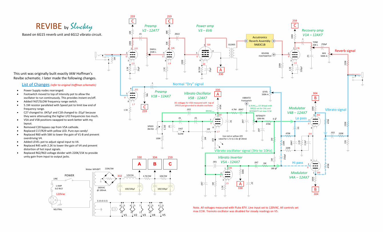
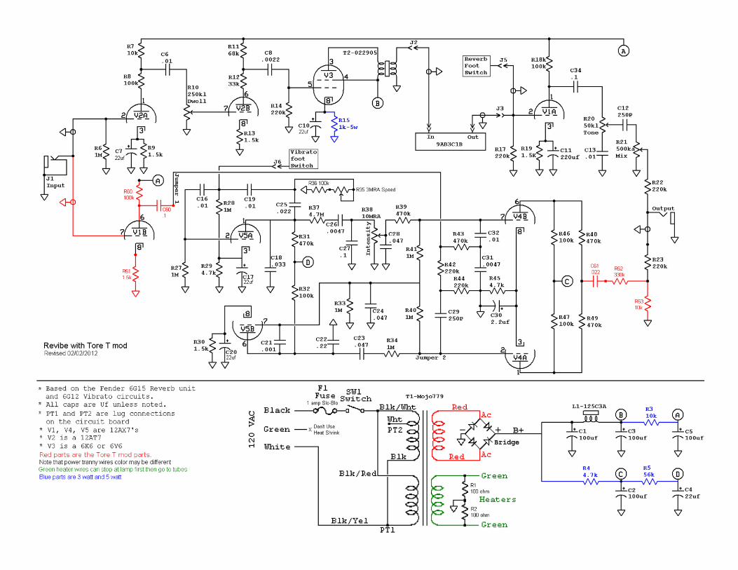
Note. All voltages measured with Fluke 87V. Line input set to 120VAC. All controls set max CCW. Tremolo oscillator was disabled for steady readings on V5.
221
122
1.9
0 0
1.9
126320
330
23
0
1.7
0
259 259
259
330
259
170
1.3
0
304
252
2.4
0
250
0228
1.5
0
187
0
6.3VACrms (17.8Vpp) with SPEED set for 5Hz and
INTENSITY set max CCW
REVIBE by SluckeyBased on 6G15 reverb unit and 6G12 vibrato circuit.
330100/100µF100/100µF
125C3A 4.7K/3W 10K/3W
C259
B304
A330
3.15-0-3.15
260VAC@ 100mA
V5V2V1
4 4
99
5 5
V4
4
9
5
NEUTRAL
LINE
1 AMPSLO BLO
POWER
Weber WRVBPT
4
9
5
120Vac
7
2V3
304
Power Supply nodes rearranged.Footswitch moved to top of Intensity pot to allow the oscillator to run continuously. This provides instant on/off.Added FAST/SLOW frequency range switch. 5.1M resistor paralleled with Speed pot to limit low end of frequency range. C27 changed to .047µF and C18 changed to .01µF because they were attenuating the higher LFO frequencies too much. V5A and V5B positions swapped to work better with my layout.Removed C20 bypass cap from V5A cathode. Replaced C17/R29 with yellow LED. Pure eye candy! Replaced R60 with 56K to lower the gain of V1-B and prevent overdriving V4.Added LEVEL pot to adjust signal input to V4.Replaced R45 with 2.2K to lower the gain of V4 and prevent distortion of hot input signals.Replaced R62/R63 voltage divider with 220K/15K to provide unity gain from input to output jacks.
List of Changes (refer to original Hoffman schematic)
0
180
This unit was originally built exactly IAW Hoffman’s Revibe schematic. I later made the following changes.
Normal “Dry” signal
Hi pass
Lo pass
Vibrato signal
Vibrato InverterV5A - 12AX7
ModulatorV4A – 12AX7
PreampV2 - 12AT7
Power ampV3 – 6V6
Use red or yellow LEDrated for 1.7v to 2.0v @ 20mA
84VACrms
Reverb signal
Vibrato oscillator signal (3Hz to 10Hz)
220K/3W
332
DC voltages for V5B measured with top of SPEED pot grounded to disable oscillator.
LEVEL500K-A
4
5 6
78
12
3
12
345
67
89
12
345
67
89
12
345
67
89
12
345
67
89
125A35A OT
REV FS
Tone50K-L
T
S
GReverbLevel
500K-A
TS
GIntensity10M-RA
Speed3M-RA
Dwell250K-LSlow/Fast
InputOutput
+ +
250µF 50V
.01µF 400v250p
0.1µF 400v
.01µF 630v
.0022µF 630v
+ +
22µF
.022µF 630v
250p
.01µF 630v.0047µF
630v
C
0.1µF 400v
+ +
22µF0.047µF 250v
0.047µF 250v
.047µF 400v
0.22µF 400v
.01µF 400v
.01µF 400v
.022µF 400v
VIB FS
LED
A
REV Return
+ +
2.2µF
VIB FS
REV Send
B
.0047µF 630v
.01µF 630v
HT
HT
6.3
6.3
B+
+ AC
-AC
.01µF 400v
.047µF
A
RG 3
16
.001µF
63
0v
V5 V4V3
V2 V1
Vibrato Level
500K-A
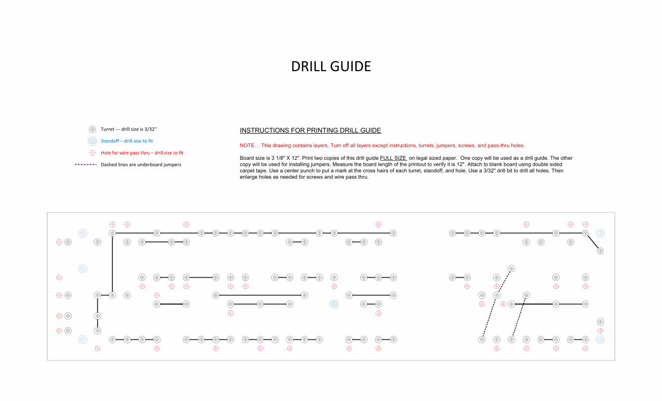
Turret --- drill size is 3/32"
Hole for wire pass thru – drill size to fit
Standoff – drill size to fit
Dashed lines are underboard jumpers
INSTRUCTIONS FOR PRINTING DRILL GUIDE
NOTE… This drawing contains layers. Turn off all layers except instructions, turrets, jumpers, screws, and pass-thru holes.
Board size is 3 1/8" X 12". Print two copies of this drill guide FULL SIZE on legal sized paper. One copy will be used as a drill guide. The other copy will be used for installing jumpers. Measure the board length of the printout to verify it is 12". Attach to blank board using double sided carpet tape. Use a center punch to put a mark at the cross hairs of each turret, standoff, and hole. Use a 3/32" drill bit to drill all holes. Then enlarge holes as needed for screws and wire pass thru.
DRILL GUIDE
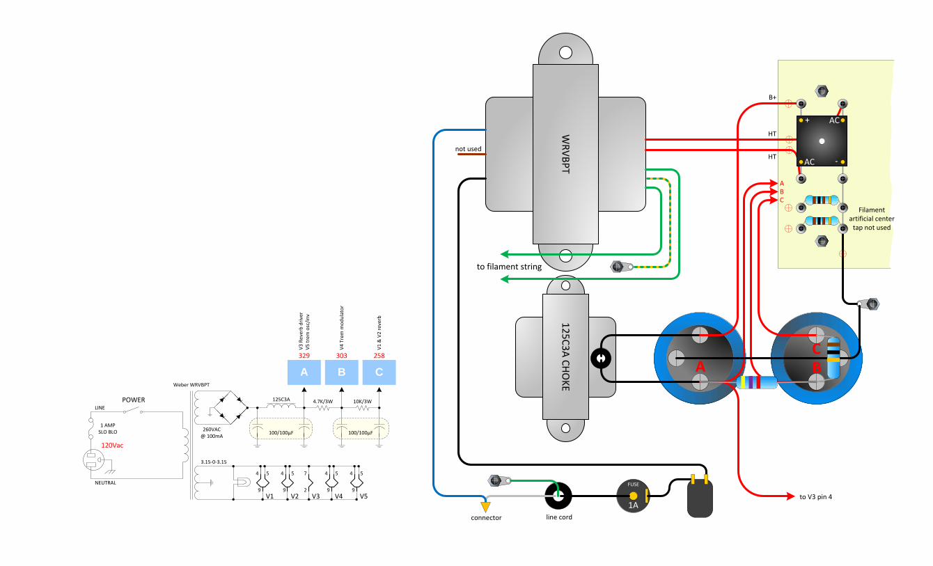
125C3A CHOKE
ACB
WRVBPT
to filament string
FUSE
connector
1A
not used
B+
+ AC
-AC
HT
HT
Filamentartificial center
tap not used
100/100µF100/100µF
125C3A 4.7K/3W 10K/3W
C258
B303
A329
V3 R
ever
b dr
iver
V5 tr
em o
sc/in
v
V4 T
rem
mod
ulat
or
V1 &
V2
reve
rb
3.15-0-3.15
260VAC@ 100mA
V5V2V1
4 4
99
5 5
V4
4
9
5
NEUTRAL
LINE
1 AMPSLO BLO
POWER
Weber WRVBPT
4
9
5
120Vac
7
2V3 to V3 pin 4
ABC
line cord
1
23
456
78
9 1
23
456
78
9 1
23
456
78
9 1
23
456
78
94 5
67
81
23
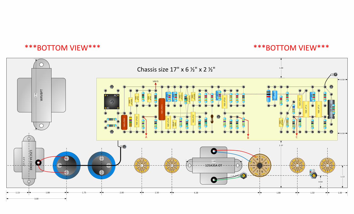
1.001.501.881.50 4.38
125A35A OT2.80
125C3A CHOKE
2.5" x 1.5"
2.001.75
WRV
BPT
3.56
0.50
0.50
Chassis size 17" x 6 ½" x 2 ½"
1.881.13
3.00
1.13
0.63
+ +
250µF 50V
0.1µF 400v
.01µF 630v
.0022µF 630v
+ +
22µF
.022µF 630v
250p
.01µF 630v.0047µF
630v
C
0.1µF 400v
+ +
22µF0.047µF 250v
0.047µF 250v
+ +
22µF
+ +
22µF
.001
µF
630v
.047µF 400v
0.22µF 400v
.01µF 400v
.01µF 400v
.022µF 400v
VIB FS
+ +
2.2µFB
+ AC
-AC
.0047µF 630v
.033µF 630v
A
1.00
2.37
***BOTTOM VIEW*** ***BOTTOM VIEW***
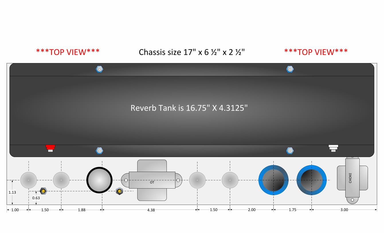
1.00 1.50 1.88 1.504.38
OT CHO
KE
2.00 1.75
Chassis size 17" x 6 ½" x 2 ½"
3.00
1.130.63
Reverb Tank is 16.75" X 4.3125"
Chassis size 17" x 6 ½" x 2 ½"***TOP VIEW*** ***TOP VIEW***
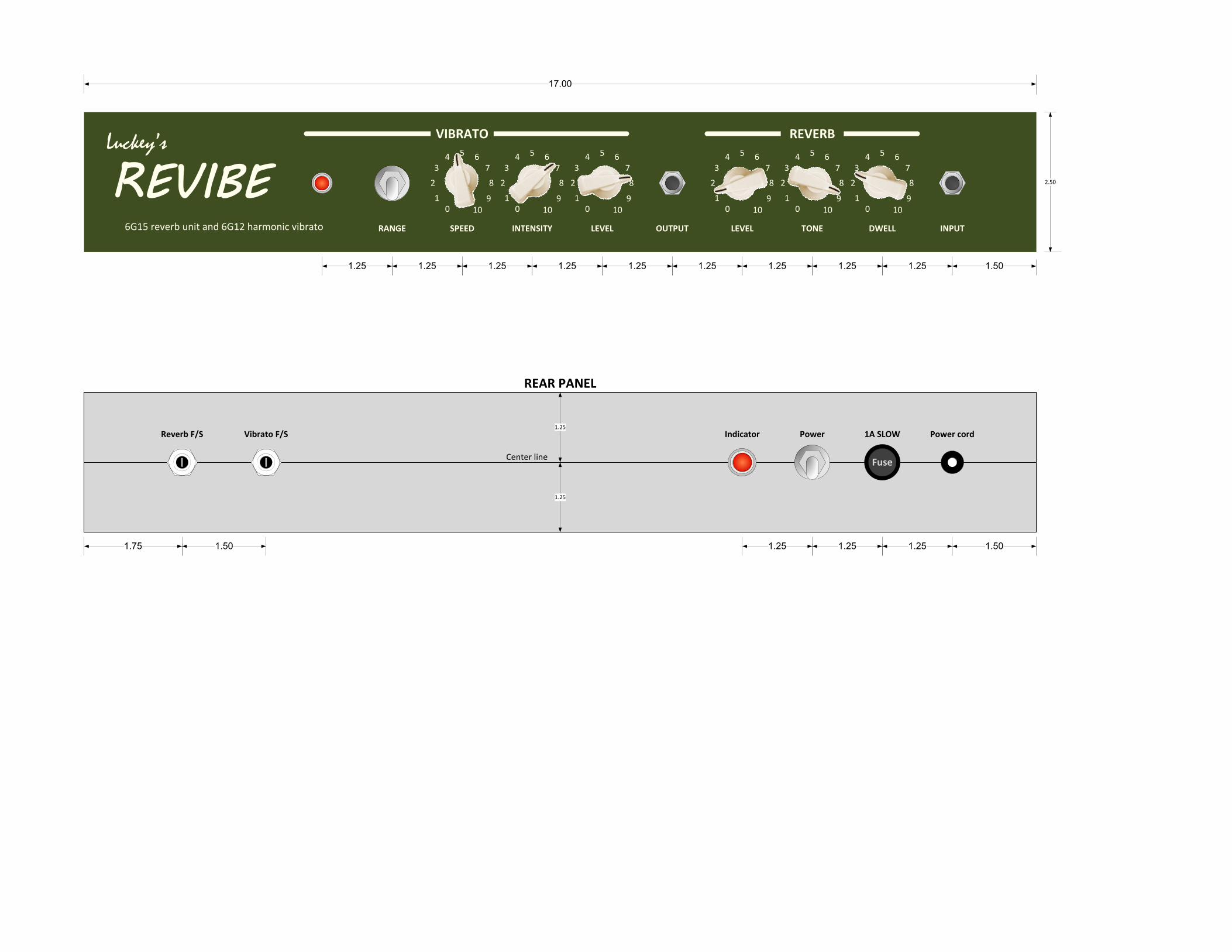
17.00
1.501.251.251.251.251.251.251.251.25
DWELL INPUTTONEOUTPUT LEVELINTENSITYRANGE SPEED
5 67
8
9100
1
2
34 5 6
7
8
9100
1
2
34 5 6
7
8
9100
1
2
34 5 6
7
8
9100
1
2
34
REVERBVIBRATO
6G15 reverb unit and 6G12 harmonic vibrato
Luckey’s5 6
7
8
9100
1
2
34
2.50
LEVEL
5 67
8
9100
1
2
34
1.25
1.75 1.50 1.25 1.25
Reverb F/S Vibrato F/S
1.501.25
Fuse
Power cord1A SLOWPowerIndicator
1.25
Center line
REAR PANEL
1.25


![Laboratory Evaluation of Calcium Carbonate Particle Size Selection for Drill in Fluids[1]](https://img.pdfslide.net/doc/110x75/5572073d497959fc0b8ba604/laboratory-evaluation-of-calcium-carbonate-particle-size-selection-for-drill-in-fluids1.jpg)

