Embed Size (px)
Citation preview
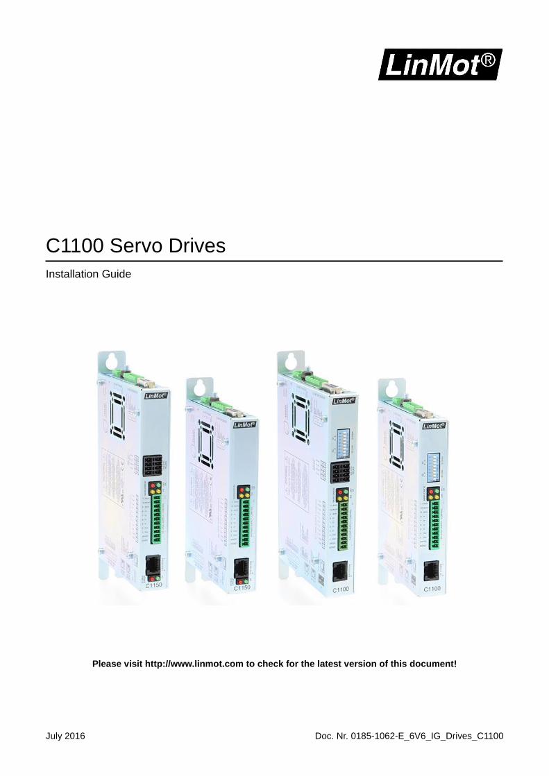
July 2016 Doc. Nr. 0185-1062-E_6V6_IG_Drives_C1100
C1100 Servo Drives
Installation Guide
Please visit http://www.linmot.com to check for the latest version of this document!
© 2016 NTI AG This work is protected by copyright. Under the copyright laws, this publication may not be reproduced or transmitted in any form, electronic or mechanical, including photocopying, recording, microfilm, storing in an information retrieval system, not even for didactical use, or translating, in whole or in part, without the prior written consent of NTI AG. LinMot® is a registered trademark of NTI AG. Note The information in this documentation reflects the stage of development at the time of press and is therefore without obligation. NTI AG reserves itself the right to make changes at any time and without notice to reflect further technical advance or product improvement. NTI AG LinMot® Bodenaeckerstrasse 2 CH-8957 Spreitenbach
Tel.: +41 (0)56 419 91 91 Fax: +41 (0)56 419 91 92
Email: [email protected] Homepage: www.LinMot.com
Installation Guide C1100
NTI AG / LinMot Page 3 of 29
Table of Contents
Table of Contents .................................................................................................................................................. 3 1 Important Safety Instructions ........................................................................................................................... 4 2 System Overview................................................................................................................................................ 6 3 Interfaces ............................................................................................................................................................ 7
4 Functionality ....................................................................................................................................................... 8 5 Software .............................................................................................................................................................. 8 6 Power Supply and Grounding ........................................................................................................................... 9 7 Description of the connectors / Interfaces .................................................................................................... 10
7.1 PE .................................................................................................................................................................. 10
7.2 X1 .................................................................................................................................................................. 10 7.3 X2 .................................................................................................................................................................. 10 7.4 X3 .................................................................................................................................................................. 11 7.5 X4 .................................................................................................................................................................. 12
7.6 X7 – X8 .......................................................................................................................................................... 12 7.7 X13 ................................................................................................................................................................ 13 7.8 X17 – X18 ...................................................................................................................................................... 13
7.9 X19 ................................................................................................................................................................ 14 7.10 X33 .............................................................................................................................................................. 14
7.11 S1 – S2 ........................................................................................................................................................ 14 7.12 S4 ................................................................................................................................................................ 15
7.13 S5 ................................................................................................................................................................ 15 7.14 LEDs ............................................................................................................................................................ 15 7.15 RT Bus LEDs ............................................................................................................................................... 15
8 LED Blink Codes .............................................................................................................................................. 16 9 Safety Wiring .................................................................................................................................................... 17
10 Physical Dimension ....................................................................................................................................... 19
11 Power Supply Requirements ......................................................................................................................... 20
11.1 Motor Power Supply .................................................................................................................................... 20 11.2 Signal Power Supply ................................................................................................................................... 20
12 Regeneration Resistor ................................................................................................................................... 20 13 Safety notes for the installation according UL ........................................................................................... 21 14 Ordering Information ..................................................................................................................................... 22 15 International Certifications ............................................................................................................................ 23
16 Declaration of Conformity CE-Marking ........................................................................................................ 28 Contact & Support ............................................................................................................................................... 29
Installation Guide C1100
Page 4 of 29 NTI AG / LinMot
1 Important Safety Instructions
For your personal safety Disregarding the following safety measures can lead to severe injury to persons and damage to material:
Only use the product as directed. Never commission the product in the event of visible damage. Never commission the product before assembly has been completed. Do not carry out any technical changes on the product. Only use the accessories approved for the product. Only use original spare parts from LinMot. Observe all regulations for the prevention of accidents, directives and laws applicable on site. Transport, installation, commissioning and maintenance work must only be carried out by qualified
personnel. Observe IEC 364 and CENELEC HD 384 or DIN VDE 0100 and IEC report 664 or
DIN VDE 0110 and all national regulations for the prevention of accidents. According to the basic safety information, qualified, skilled personnel are persons who are familiar with
the assembly, installation, commissioning, and operation of the product and who have the qualifications necessary for their occupation.
Observe all specifications in this documentation. This is the condition for safe and trouble−free operation and the achievement of the specified product
features. The procedural notes and circuit details described in this documentation are only proposals. It is up to
the user to check whether they can be transferred to the particular applications. NTI AG / LinMot does not accept any liability for the suitability of the procedures and circuit proposals described.
LinMot servo drives and the accessory components can include live and moving parts (depending on their type of protection) during operation. Surfaces can be hot. Non−authorized removal of the required cover, inappropriate use, incorrect installation or operation
create the risk of severe injury to persons or damage to material assets. For more information, please see the documentation.
High amounts of energy are produced in the drive. Therefore it is required to wear personal protective equipment (body protection, headgear, eye protection, hand guard).
Application as directed
Drives are components which are designed for installation in electrical systems or machines. They are not to be used as domestic appliances, but only for industrial purposes according to EN 61000−3−2.
When drives are installed into machines, commissioning (i.e. starting of the operation as directed) is prohibited until it is proven that the machine complies with the regulations of the EC Directive 98/37/EC (Machinery Directive); EN 60204 must be observed.
Commissioning (i.e. starting of the operation as directed) is only allowed when there is compliance with the EMC Directive (2004/108/EC).
The technical data and supply conditions can be obtained from the nameplate and the documentation. They must be strictly observed.
Transport, storage
Please observe the notes on transport, storage, and appropriate handling. Observe the climatic conditions according to the technical data.
Installation Guide C1100
NTI AG / LinMot Page 5 of 29
Installation The drives must be installed and cooled according to the instructions given in the corresponding
documentation. The ambient air must not exceed degree of pollution 2 according to EN 61800−5−1. Ensure proper handling and avoid excessive mechanical stress. Do not bend any components and do not
change any insulation distances during transport or handling. Do not touch any electronic components and contacts.
Drives contain electrostatic sensitive devices which can easily be damaged by inappropriate handling. Do not damage or destroy any electrical components since this might endanger your health!
Electrical connection
When working on live drives, observe the applicable national regulations for the prevention of accidents.
The electrical installation must be carried out according to the appropriate regulations (e.g. cable
cross−sections, fuses, PE connection). Additional information can be obtained from the documentation.
This product can cause high-frequency interferences in non-industrial environments which can require
measures for interference suppression.
Operation
If necessary, systems including drives must be equipped with additional monitoring and protection devices according to the valid safety regulations (e.g. law on technical equipment, regulations for the prevention of accidents). The drives can be adapted to your application. Please observe the corresponding information given in the documentation.
After the drive has been disconnected from the supply voltage, all live components and power connections must not be touched immediately because capacitors can still be charged. Please observe the corresponding stickers on the drive. All protection covers and doors must be shut during operation.
Protection of persons
The power terminals Ph1+, Ph1-, Ph2+, Ph2- and PWR+ remain live for at least 5 minutes after disconnecting from the power supplies.
Before servicing, disconnect supply, wait 5 minutes and measure between PWR+ and PGND to be
sure that the capacitors have discharged below 42VDC.
The heat sink of the drive can have an operating temperature of > 80 °C: Contact with the heat sink results in burns.
Installation Guide C1100
Page 6 of 29 NTI AG / LinMot
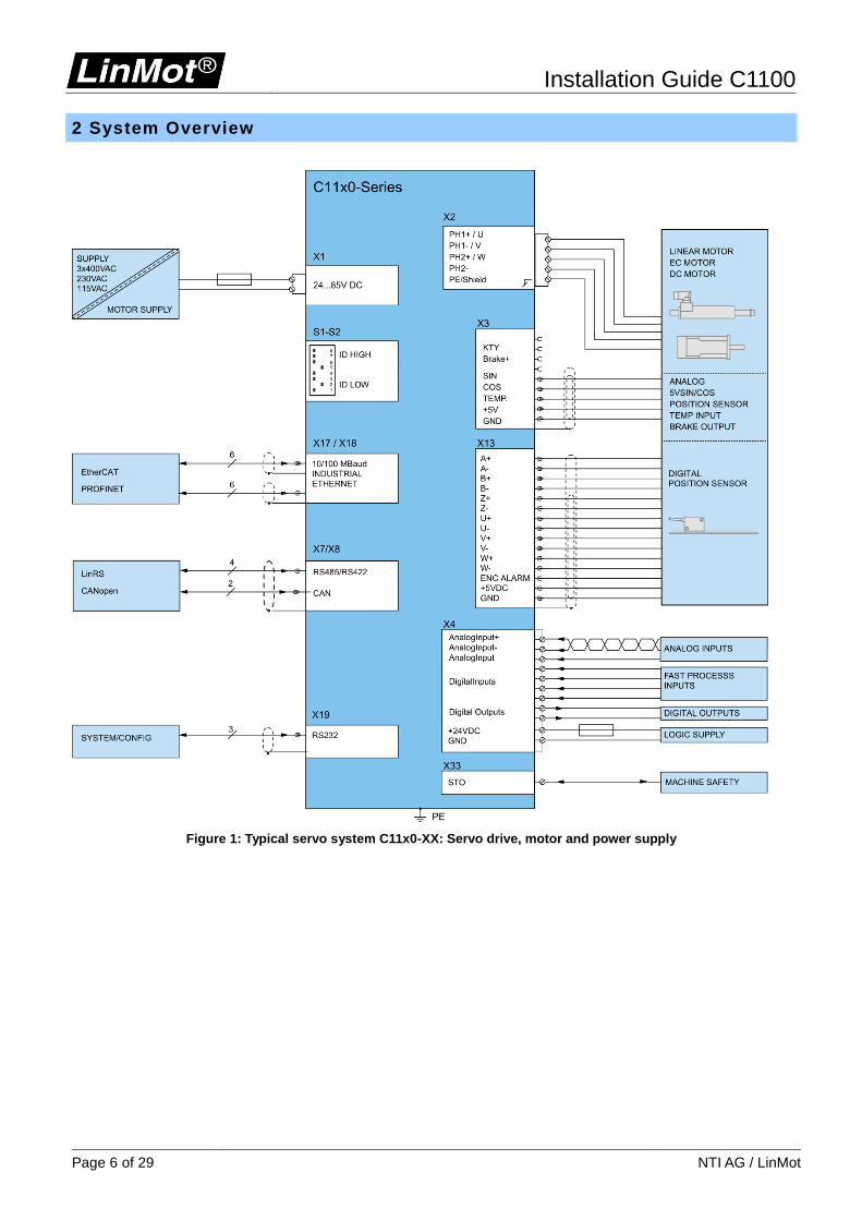
2 System Overview
Figure 1: Typical servo system C11x0-XX: Servo drive, motor and power supply
Installation Guide C1100
NTI AG / LinMot Page 7 of 29
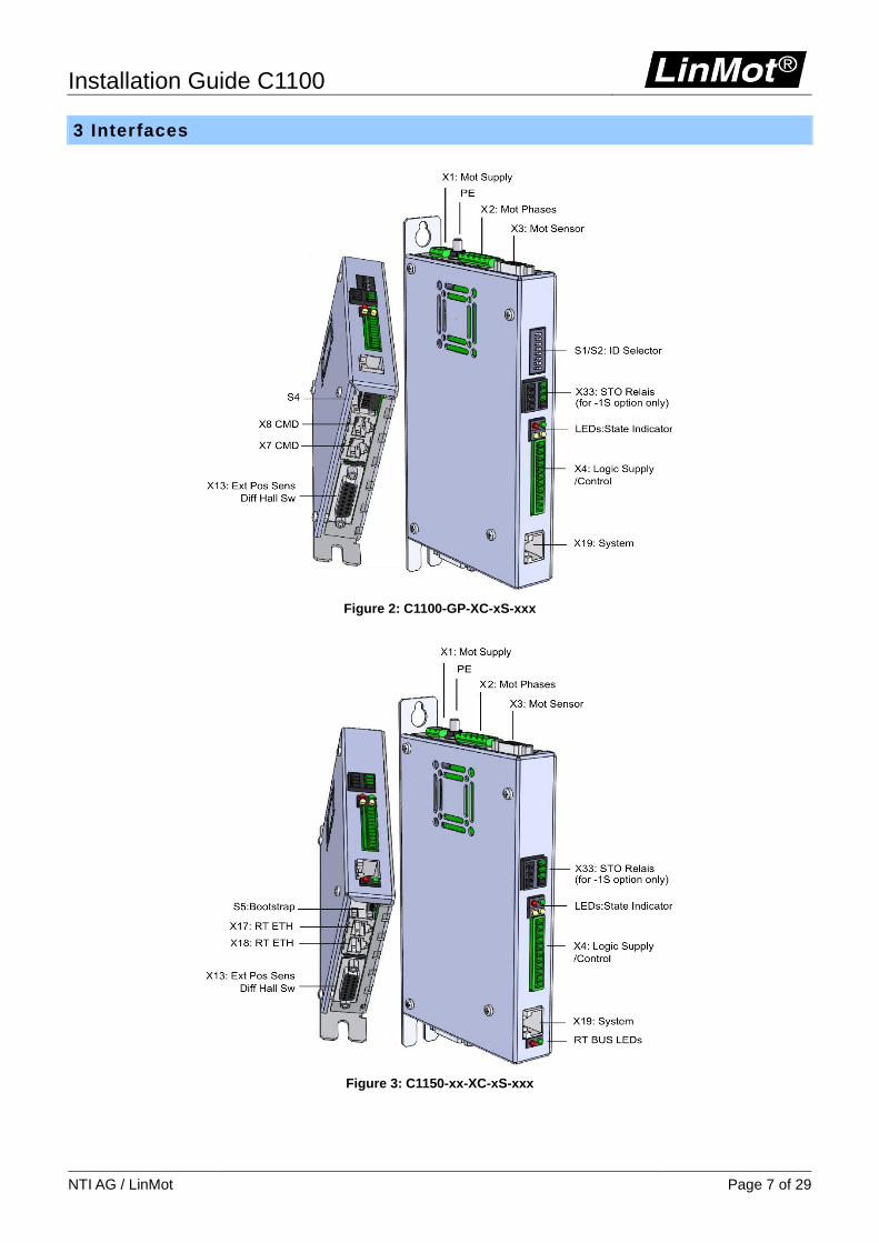
3 Interfaces
Figure 2: C1100-GP-XC-xS-xxx
Figure 3: C1150-xx-XC-xS-xxx
Installation Guide C1100
Page 8 of 29 NTI AG / LinMot
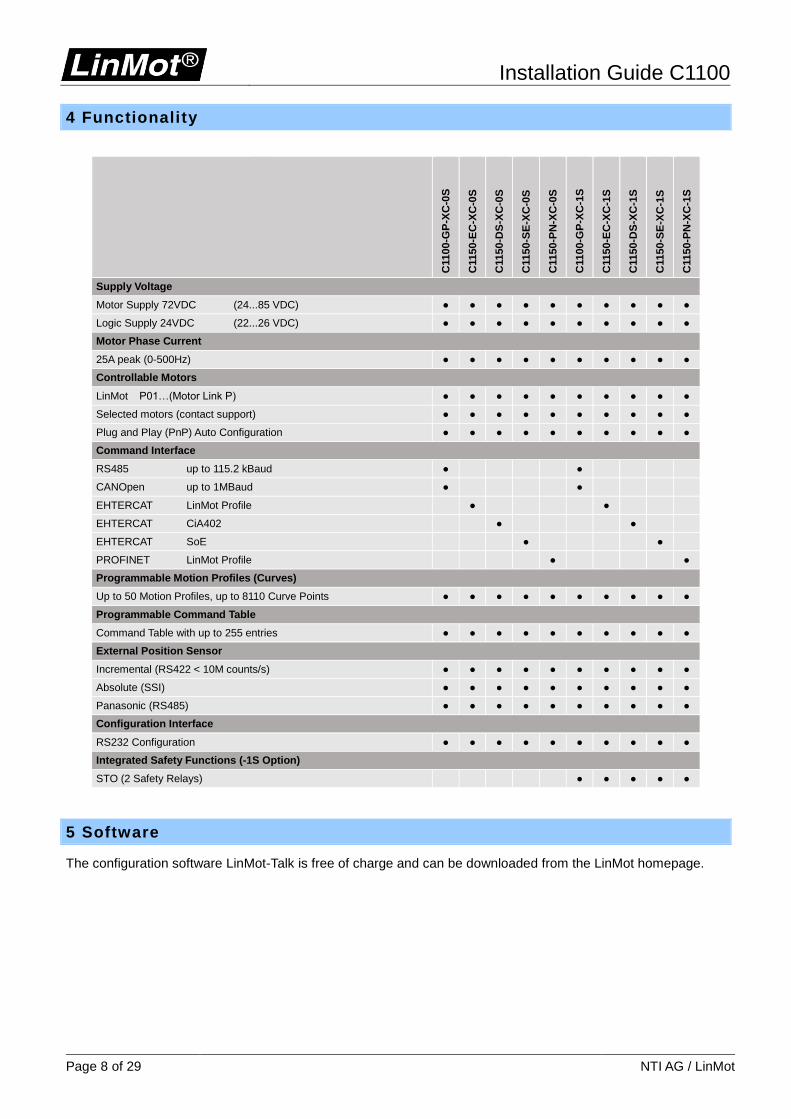
4 Functionality
C1100-G
P-X
C-0
S
C1150-E
C-X
C-0
S
C1150-D
S-X
C-0
S
C1150-S
E-X
C-0
S
C1150-P
N-X
C-0
S
C1100-G
P-X
C-1
S
C1150-E
C-X
C-1
S
C1150-D
S-X
C-1
S
C1150-S
E-X
C-1
S
C1150-P
N-X
C-1
S
Supply Voltage
Motor Supply 72VDC (24...85 VDC)
Logic Supply 24VDC (22...26 VDC)
Motor Phase Current
25A peak (0-500Hz)
Controllable Motors
LinMot P01…(Motor Link P)
Selected motors (contact support)
Plug and Play (PnP) Auto Configuration
Command Interface
RS485 up to 115.2 kBaud
CANOpen up to 1MBaud
EHTERCAT LinMot Profile
EHTERCAT CiA402
EHTERCAT SoE
PROFINET LinMot Profile
Programmable Motion Profiles (Curves)
Up to 50 Motion Profiles, up to 8110 Curve Points
Programmable Command Table
Command Table with up to 255 entries
External Position Sensor
Incremental (RS422 < 10M counts/s)
Absolute (SSI)
Panasonic (RS485)
Configuration Interface
RS232 Configuration
Integrated Safety Functions (-1S Option)
STO (2 Safety Relays)
5 Software
The configuration software LinMot-Talk is free of charge and can be downloaded from the LinMot homepage.
Installation Guide C1100
NTI AG / LinMot Page 9 of 29
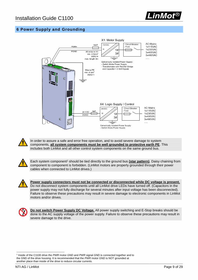
6 Power Supply and Grounding
In order to assure a safe and error free operation, and to avoid severe damage to system components, all system components must be well grounded to protective earth PE. This
includes both LinMot and all other control system components on the same ground bus.
Each system component1 should be tied directly to the ground bus (star pattern). Daisy chaining from component to component is forbidden. (LinMot motors are properly grounded through their power cables when connected to LinMot drives.)
Power supply connectors must not be connected or disconnected while DC voltage is present. Do not disconnect system components until all LinMot drive LEDs have turned off. (Capacitors in the power supply may not fully discharge for several minutes after input voltage has been disconnected). Failure to observe these precautions may result in severe damage to electronic components in LinMot motors and/or drives.
Do not switch Power Supply DC Voltage. All power supply switching and E-Stop breaks should be done to the AC supply voltage of the power supply. Failure to observe these precautions may result in severe damage to the drive.
1 Inside of the C1100 drive the PWR motor GND and PWR signal GND is connected together and to the GND of the drive housing. It is recommended that the PWR motor GND is NOT grounded at another place than inside of the drive to reduce circular currents.
Installation Guide C1100
Page 10 of 29 NTI AG / LinMot
7 Description of the connectors / Interfaces
7.1 PE
PE Protective Earth
PE Use min. 4mm2 (AWG11)
Tightening torque: 2Nm (18 lbin)
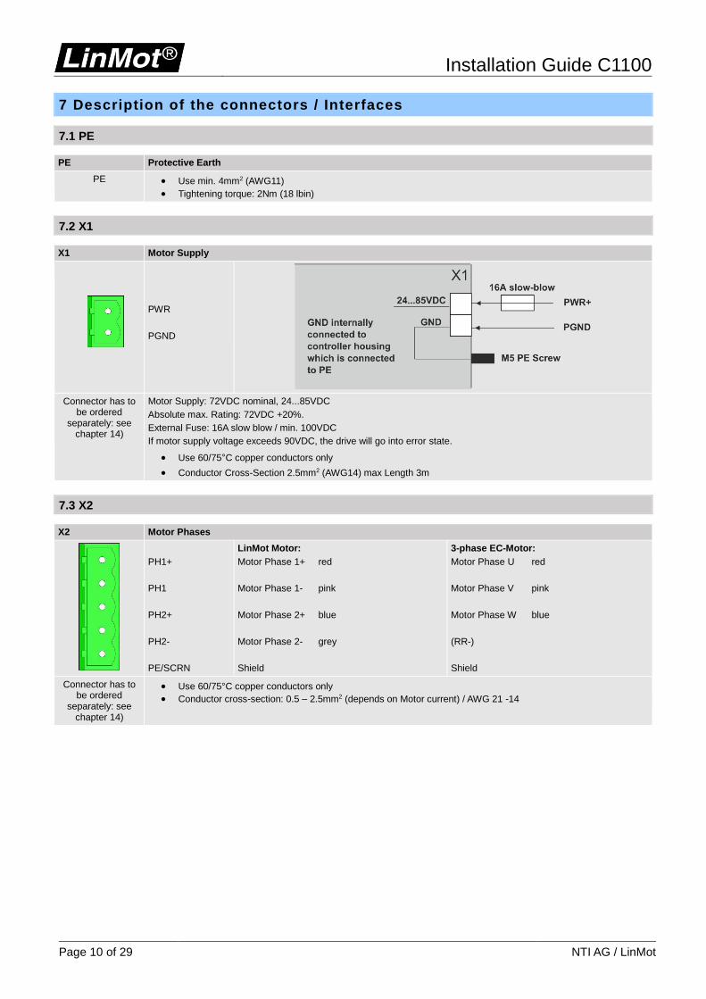
7.2 X1
X1 Motor Supply
PWR
PGND
Connector has to be ordered
separately: see chapter 14)
Motor Supply: 72VDC nominal, 24...85VDC
Absolute max. Rating: 72VDC +20%.
External Fuse: 16A slow blow / min. 100VDC
If motor supply voltage exceeds 90VDC, the drive will go into error state.
Use 60/75°C copper conductors only
Conductor Cross-Section 2.5mm2 (AWG14) max Length 3m
7.3 X2
X2 Motor Phases
PH1+
PH1
PH2+
PH2-
PE/SCRN
LinMot Motor:
Motor Phase 1+ red
Motor Phase 1- pink
Motor Phase 2+ blue
Motor Phase 2- grey
Shield
3-phase EC-Motor:
Motor Phase U red
Motor Phase V pink
Motor Phase W blue
(RR-)
Shield
Connector has to be ordered
separately: see chapter 14)
Use 60/75°C copper conductors only
Conductor cross-section: 0.5 – 2.5mm2 (depends on Motor current) / AWG 21 -14
Installation Guide C1100
NTI AG / LinMot Page 11 of 29
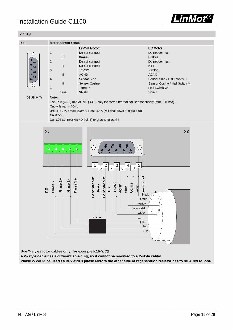
7.4 X3
X3 Motor Sensor / Brake
1
6
2
7
3
8
4
9
5
case
LinMot Motor:
Do not connect
Brake+
Do not connect
Do not connect
+5VDC
AGND
Sensor Sine
Sensor Cosine
Temp In
Shield
EC Motor:
Do not connect
Brake+
Do not connect
KTY
+5VDC
AGND
Sensor Sine / Hall Switch U
Sensor Cosine / Hall Switch V
Hall Switch W
Shield
DSUB-9 (f) Note:
Use +5V (X3.3) and AGND (X3.8) only for motor internal hall sensor supply (max. 100mA).
Cable length < 30m.
Brake+: 24V / max.500mA, Peak 1.4A (will shut down if exceeded)
Caution:
Do NOT connect AGND (X3.8) to ground or earth!
Use Y-style motor cables only (for example K15-Y/C)!
A W-style cable has a different shielding, so it cannot be modified to a Y-style cable!
Phase 2- could be used as RR- with 3 phase Motors the other side of regeneration resistor has to be wired to PWR
Installation Guide C1100
Page 12 of 29 NTI AG / LinMot
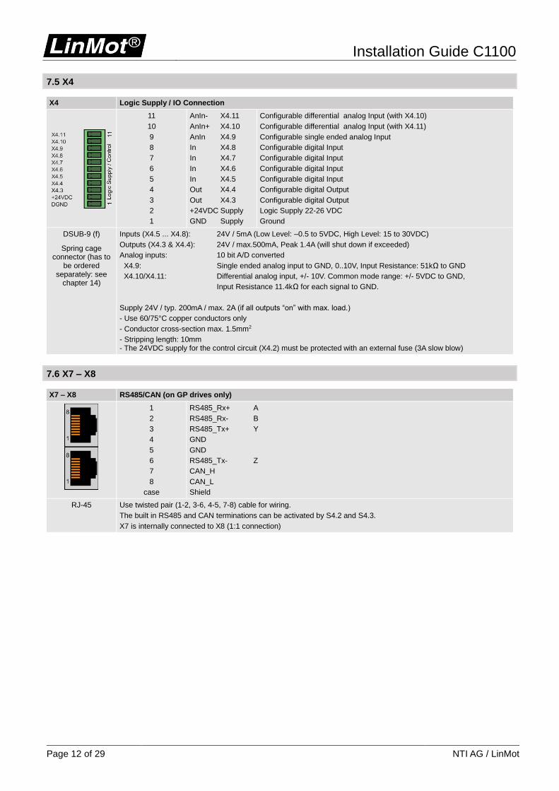
7.5 X4
X4 Logic Supply / IO Connection
11
10
9
8
7
6
5
4
3
2
1
AnIn- X4.11
AnIn+ X4.10
AnIn X4.9
In X4.8
In X4.7
In X4.6
In X4.5
Out X4.4
Out X4.3
+24VDC Supply
GND Supply
Configurable differential analog Input (with X4.10)
Configurable differential analog Input (with X4.11)
Configurable single ended analog Input
Configurable digital Input
Configurable digital Input
Configurable digital Input
Configurable digital Input
Configurable digital Output
Configurable digital Output
Logic Supply 22-26 VDC
Ground
DSUB-9 (f)
Spring cage connector (has to
be ordered separately: see
chapter 14)
Inputs (X4.5 ... X4.8): 24V / 5mA (Low Level: –0.5 to 5VDC, High Level: 15 to 30VDC)
Outputs (X4.3 & X4.4): 24V / max.500mA, Peak 1.4A (will shut down if exceeded)
Analog inputs: 10 bit A/D converted
X4.9: Single ended analog input to GND, 0..10V, Input Resistance: 51kΩ to GND
X4.10/X4.11: Differential analog input, +/- 10V. Common mode range: +/- 5VDC to GND,
Input Resistance 11.4kΩ for each signal to GND.
Supply 24V / typ. 200mA / max. 2A (if all outputs “on” with max. load.)
- Use 60/75°C copper conductors only
- Conductor cross-section max. 1.5mm2
- Stripping length: 10mm - The 24VDC supply for the control circuit (X4.2) must be protected with an external fuse (3A slow blow)
7.6 X7 – X8
X7 – X8 RS485/CAN (on GP drives only)
1
2
3
4
5
6
7
8
case
RS485_Rx+ A
RS485_Rx- B
RS485_Tx+ Y
GND
GND
RS485_Tx- Z
CAN_H
CAN_L
Shield
RJ-45 Use twisted pair (1-2, 3-6, 4-5, 7-8) cable for wiring.
The built in RS485 and CAN terminations can be activated by S4.2 and S4.3.
X7 is internally connected to X8 (1:1 connection)

Installation Guide C1100
NTI AG / LinMot Page 13 of 29
7.7 X13
X13 External Position Sensor Differential Hall Switches
1
9
2
10
3
11
4
12
5
13
6
14
7
15
8
case
ABZ with Hall Switches
+5V DC
A+
A-
B+
B-
Z+
Z-
Encoder Alarm
GND
U+
U-
V+
V-
W+
W-
Shield
SSI
+5V DC
A+
A-
B+
B-
Data+
Data-
Encoder Alarm
GND
nc
nc
nc
nc
Clk+
Clk-
Shield
DSUB-15 (f) Position Encoder Inputs (RS422):
Max. counting frequency: 10 Mcounts/s with quadrature decoding, 100ns minimal edge separation
Differential Hall Switch Inputs (RS422):
Input Frequency: <1kHz
Enc. Alarm In:
5V / 1mA
Sensor Supply:
5VDC max 100mA
7.8 X17 – X18
X17 – X18 RealTime Ethernet 10/100 Mbit/s (on EC and PN drives only)
X17 RT ETH In
X18 RT ETH Out
Specification depends on RT Bus. Please refer to according documentation.
RJ-45
Installation Guide C1100
Page 14 of 29 NTI AG / LinMot
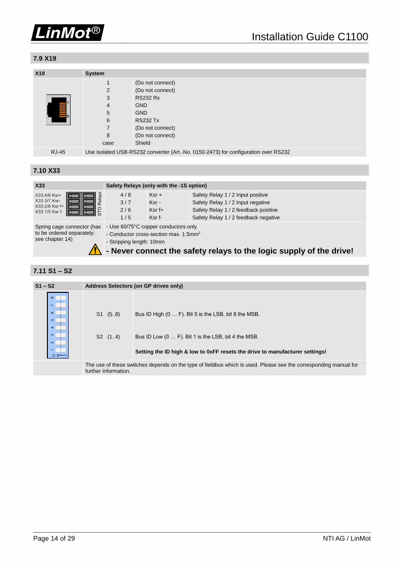
7.9 X19
X19 System
1
2
3
4
5
6
7
8
case
(Do not connect)
(Do not connect)
RS232 Rx
GND
GND
RS232 Tx
(Do not connect)
(Do not connect)
Shield
RJ-45 Use isolated USB-RS232 converter (Art.-No. 0150-2473) for configuration over RS232
7.10 X33
X33 Safety Relays (only with the -1S option)
4 / 8
3 / 7
2 / 6
1 / 5
Ksr +
Ksr -
Ksr f+
Ksr f-
Safety Relay 1 / 2 Input positive
Safety Relay 1 / 2 Input negative
Safety Relay 1 / 2 feedback positive
Safety Relay 1 / 2 feedback negative
Spring cage connector (has to be ordered separately: see chapter 14)
- Use 60/75°C copper conductors only
- Conductor cross-section max. 1.5mm2
- Stripping length: 10mm
- Never connect the safety relays to the logic supply of the drive!
7.11 S1 – S2
S1 – S2 Address Selectors (on GP drives only)
S1 (5..8)
S2 (1..4)
Bus ID High (0 … F). Bit 5 is the LSB, bit 8 the MSB.
Bus ID Low (0 … F). Bit 1 is the LSB, bit 4 the MSB.
Setting the ID high & low to 0xFF resets the drive to manufacturer settings!
The use of these switches depends on the type of fieldbus which is used. Please see the corresponding manual for further information.
Installation Guide C1100
NTI AG / LinMot Page 15 of 29
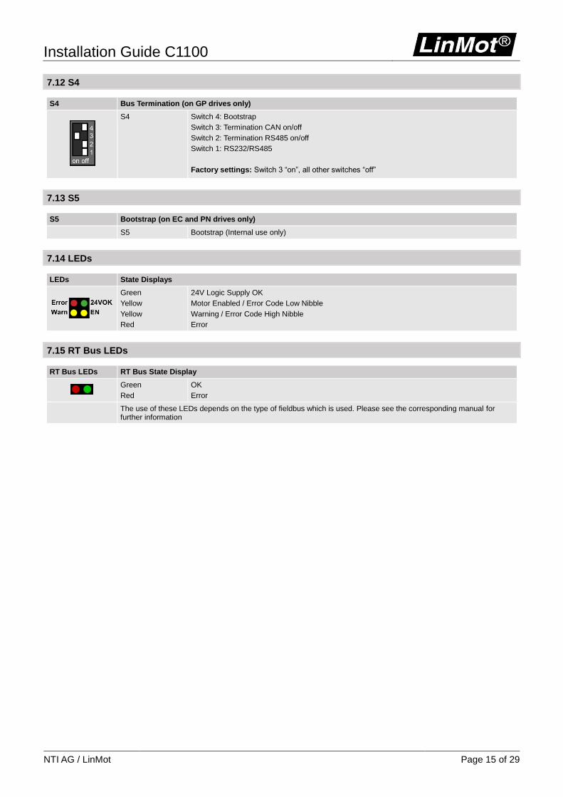
7.12 S4
S4 Bus Termination (on GP drives only)
S4 Switch 4: Bootstrap
Switch 3: Termination CAN on/off
Switch 2: Termination RS485 on/off
Switch 1: RS232/RS485
Factory settings: Switch 3 “on”, all other switches “off”
7.13 S5
S5 Bootstrap (on EC and PN drives only)
S5 Bootstrap (Internal use only)
7.14 LEDs
LEDs State Displays
Green
Yellow
Yellow
Red
24V Logic Supply OK
Motor Enabled / Error Code Low Nibble
Warning / Error Code High Nibble
Error
7.15 RT Bus LEDs
RT Bus LEDs RT Bus State Display
Green
Red
OK
Error
The use of these LEDs depends on the type of fieldbus which is used. Please see the corresponding manual for further information
Installation Guide C1100
Page 16 of 29 NTI AG / LinMot
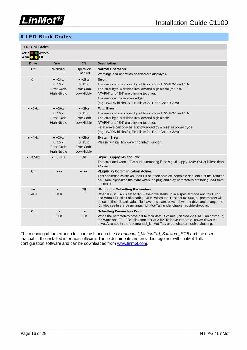
8 LED Blink Codes
LED Blink Codes
Error Warn EN Description
Off Warning Operation Enabled
Normal Operation:
Warnings and operation enabled are displayed.
On ~2Hz
0..15 x
Error Code
High Nibble
~2Hz
0..15 x
Error Code
Low Nibble
Error:
The error code is shown by a blink code with “WARN” and “EN”
The error byte is divided into low and high nibble (= 4 bit).
”WARN” and “EN” are blinking together.
The error can be acknowledged.
(e.g.: WARN blinks 3x, EN blinks 2x; Error Code = 32h)
~2Hz ~2Hz
0..15 x
Error Code
High Nibble
~2Hz
0..15 x
Error Code
Low Nibble
Fatal Error:
The error code is shown by a blink code with “WARN” and “EN”.
The error byte is divided into low and high nibble.
”WARN” and “EN” are blinking together.
Fatal errors can only be acknowledged by a reset or power cycle.
(e.g.: WARN blinks 3x, EN blinks 2x; Error Code = 32h)
~4Hz ~2Hz
0..15 x
Error Code
High Nibble
~2Hz
0..15 x
Error Code
Low Nibble
System Error:
Please reinstall firmware or contact support.
~0.5Hz ~0.5Hz On Signal Supply 24V too low:
The error and warn LEDs blink alternating if the signal supply +24V (X4.2) is less than 18VDC.
Off Plug&Play Communication Active:
This sequence (Warn on, then En on, then both off, complete sequence of the 4 states ca. 1Sec) signalizes the state when the plug and play parameters are being read from the motor.
~4Hz
~4Hz
Off Waiting for Defaulting Parameters:
When ID (S1, S2) is set to 0xFF, the drive starts up in a special mode and the Error and Warn LED blink alternating ~4Hz. When the ID ist set to 0x00, all parameters will be set to their default value. To leave this state, power down the drive and change the ID. Also see in the Usermanual_LinMot-Talk under chapter trouble shooting.
Off
~2Hz
~2Hz
Defaulting Parameters Done:
When the parameters have set to their default values (initiated via S1/S2 on power up) the Warn and En LEDs blink together at 2 Hz. To leave this state, power down the drive. Also see in the Usermanual_LinMot-Talk under chapter trouble shooting.
The meaning of the error codes can be found in the Usermanual_MotionCtrl_Software_SG5 and the user manual of the installed interface software. These documents are provided together with LinMot-Talk configuration software and can be downloaded from www.linmot.com.
Installation Guide C1100
NTI AG / LinMot Page 17 of 29
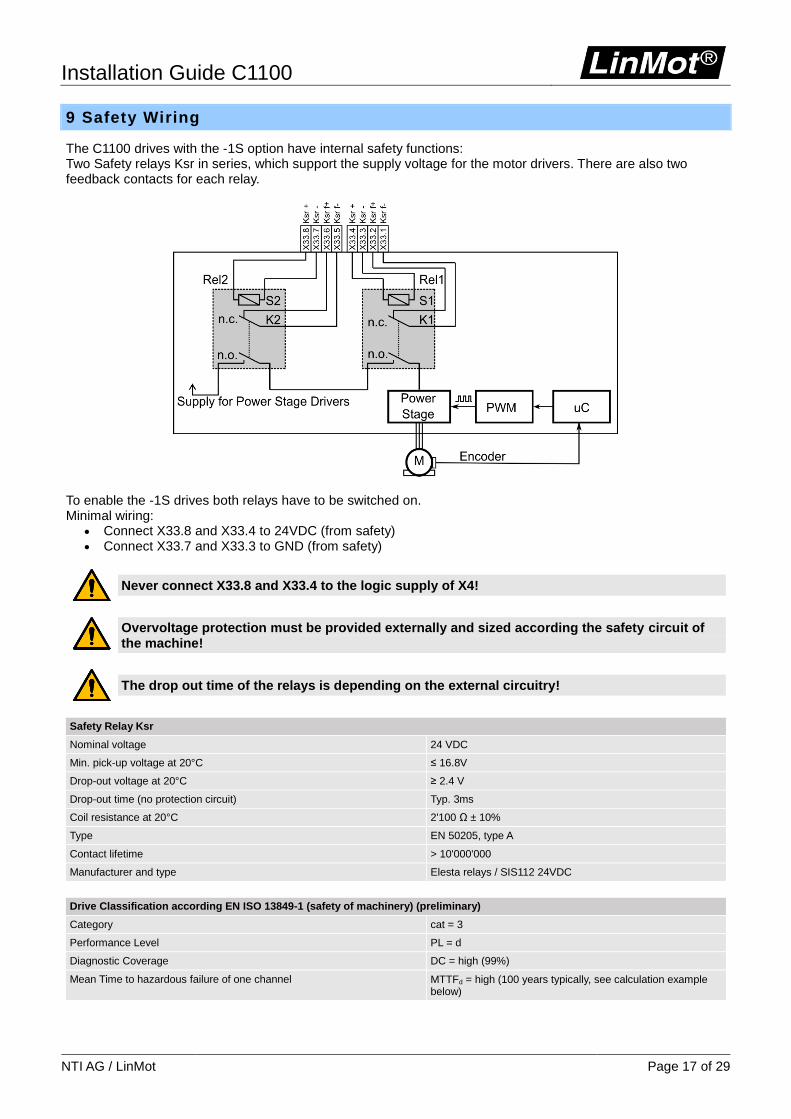
9 Safety Wiring
The C1100 drives with the -1S option have internal safety functions: Two Safety relays Ksr in series, which support the supply voltage for the motor drivers. There are also two feedback contacts for each relay.
To enable the -1S drives both relays have to be switched on. Minimal wiring:
Connect X33.8 and X33.4 to 24VDC (from safety) Connect X33.7 and X33.3 to GND (from safety)
Never connect X33.8 and X33.4 to the logic supply of X4!
Overvoltage protection must be provided externally and sized according the safety circuit of the machine!
The drop out time of the relays is depending on the external circuitry!
Safety Relay Ksr
Nominal voltage 24 VDC
Min. pick-up voltage at 20°C ≤ 16.8V
Drop-out voltage at 20°C ≥ 2.4 V
Drop-out time (no protection circuit) Typ. 3ms
Coil resistance at 20°C 2'100 Ω ± 10%
Type EN 50205, type A
Contact lifetime > 10'000'000
Manufacturer and type Elesta relays / SIS112 24VDC
Drive Classification according EN ISO 13849-1 (safety of machinery) (preliminary)
Category cat = 3
Performance Level PL = d
Diagnostic Coverage DC = high (99%)
Mean Time to hazardous failure of one channel MTTFd = high (100 years typically, see calculation example below)
Installation Guide C1100
Page 18 of 29 NTI AG / LinMot
DC (Diagnostic Coverage) is high (99%) assuming that the state of the feedback contacts is checked after each change of the state of the control contacts. MTTFd mainly depends on the number of operations of the safety relays. Example calculation of MTTFd: Assuming that the safety function is requested every 20s on a machine running 24h per day and 7 days per week. B10 = 10'000'000 B10d = 20'000'000 (according EN ISO 13849-1:2008 table C.1) nop = (24h/Tag*365.25Tage/Jahr*3600s/h) / 20s = 1'577'880 operations per year MTTFd = B10d / (0.1 x nop) = 126.75 years
(This has to be limited to 100years according the standard for further calculations) = high (100 years)
Installation Guide C1100
NTI AG / LinMot Page 19 of 29
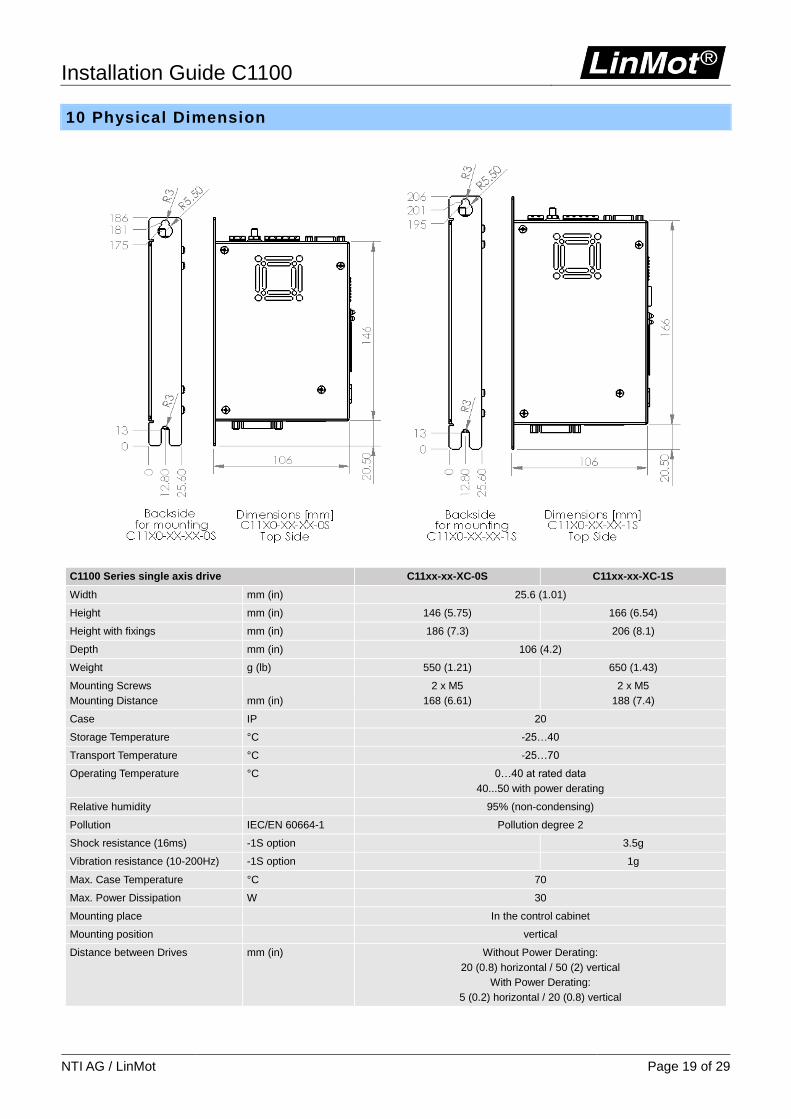
10 Physical Dimension
C1100 Series single axis drive C11xx-xx-XC-0S C11xx-xx-XC-1S
Width mm (in) 25.6 (1.01)
Height mm (in) 146 (5.75) 166 (6.54)
Height with fixings mm (in) 186 (7.3) 206 (8.1)
Depth mm (in) 106 (4.2)
Weight g (lb) 550 (1.21) 650 (1.43)
Mounting Screws
Mounting Distance
mm (in)
2 x M5
168 (6.61)
2 x M5
188 (7.4)
Case IP 20
Storage Temperature °C -25…40
Transport Temperature °C -25…70
Operating Temperature °C 0…40 at rated data
40...50 with power derating
Relative humidity 95% (non-condensing)
Pollution IEC/EN 60664-1 Pollution degree 2
Shock resistance (16ms) -1S option 3.5g
Vibration resistance (10-200Hz) -1S option 1g
Max. Case Temperature °C 70
Max. Power Dissipation W 30
Mounting place In the control cabinet
Mounting position vertical
Distance between Drives mm (in) Without Power Derating:
20 (0.8) horizontal / 50 (2) vertical
With Power Derating:
5 (0.2) horizontal / 20 (0.8) vertical
Installation Guide C1100
Page 20 of 29 NTI AG / LinMot
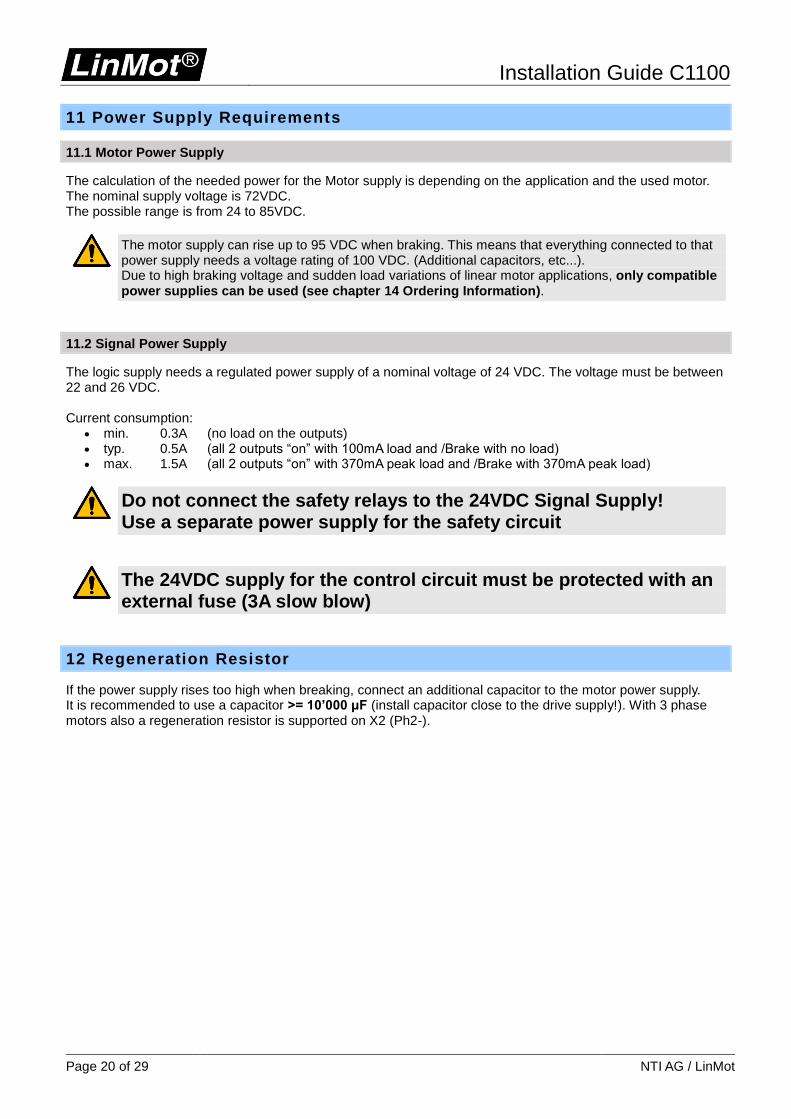
11 Power Supply Requirements
11.1 Motor Power Supply
The calculation of the needed power for the Motor supply is depending on the application and the used motor. The nominal supply voltage is 72VDC. The possible range is from 24 to 85VDC.
The motor supply can rise up to 95 VDC when braking. This means that everything connected to that power supply needs a voltage rating of 100 VDC. (Additional capacitors, etc...). Due to high braking voltage and sudden load variations of linear motor applications, only compatible power supplies can be used (see chapter 14 Ordering Information).
11.2 Signal Power Supply
The logic supply needs a regulated power supply of a nominal voltage of 24 VDC. The voltage must be between 22 and 26 VDC. Current consumption:
min. 0.3A (no load on the outputs) typ. 0.5A (all 2 outputs “on” with 100mA load and /Brake with no load) max. 1.5A (all 2 outputs “on” with 370mA peak load and /Brake with 370mA peak load)
Do not connect the safety relays to the 24VDC Signal Supply! Use a separate power supply for the safety circuit
The 24VDC supply for the control circuit must be protected with an external fuse (3A slow blow)
12 Regeneration Resistor
If the power supply rises too high when breaking, connect an additional capacitor to the motor power supply. It is recommended to use a capacitor >= 10’000 μF (install capacitor close to the drive supply!). With 3 phase motors also a regeneration resistor is supported on X2 (Ph2-).
Installation Guide C1100
NTI AG / LinMot Page 21 of 29
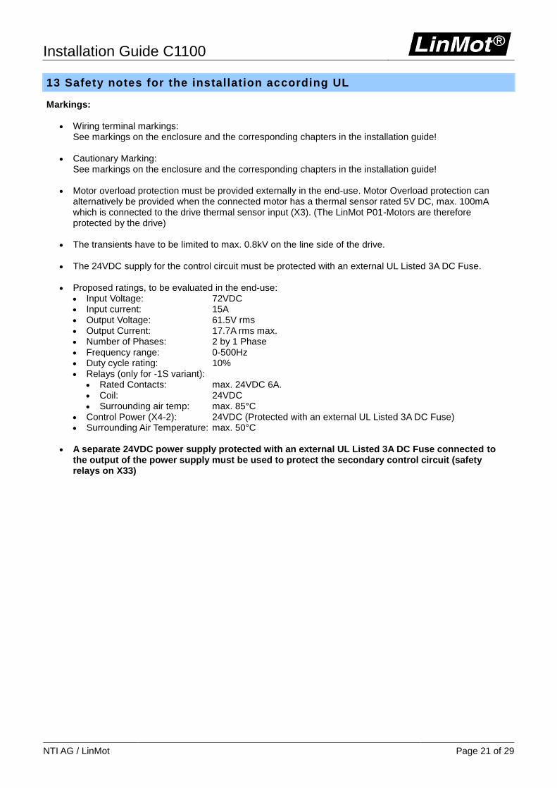
13 Safety notes for the installation according UL
Markings:
Wiring terminal markings: See markings on the enclosure and the corresponding chapters in the installation guide!
Cautionary Marking:
See markings on the enclosure and the corresponding chapters in the installation guide!
Motor overload protection must be provided externally in the end-use. Motor Overload protection can alternatively be provided when the connected motor has a thermal sensor rated 5V DC, max. 100mA which is connected to the drive thermal sensor input (X3). (The LinMot P01-Motors are therefore protected by the drive)
The transients have to be limited to max. 0.8kV on the line side of the drive.
The 24VDC supply for the control circuit must be protected with an external UL Listed 3A DC Fuse.
Proposed ratings, to be evaluated in the end-use:
Input Voltage: 72VDC Input current: 15A Output Voltage: 61.5V rms Output Current: 17.7A rms max. Number of Phases: 2 by 1 Phase Frequency range: 0-500Hz Duty cycle rating: 10% Relays (only for -1S variant):
Rated Contacts: max. 24VDC 6A. Coil: 24VDC Surrounding air temp: max. 85°C
Control Power (X4-2): 24VDC (Protected with an external UL Listed 3A DC Fuse) Surrounding Air Temperature: max. 50°C
A separate 24VDC power supply protected with an external UL Listed 3A DC Fuse connected to
the output of the power supply must be used to protect the secondary control circuit (safety relays on X33)
Installation Guide C1100
Page 22 of 29 NTI AG / LinMot
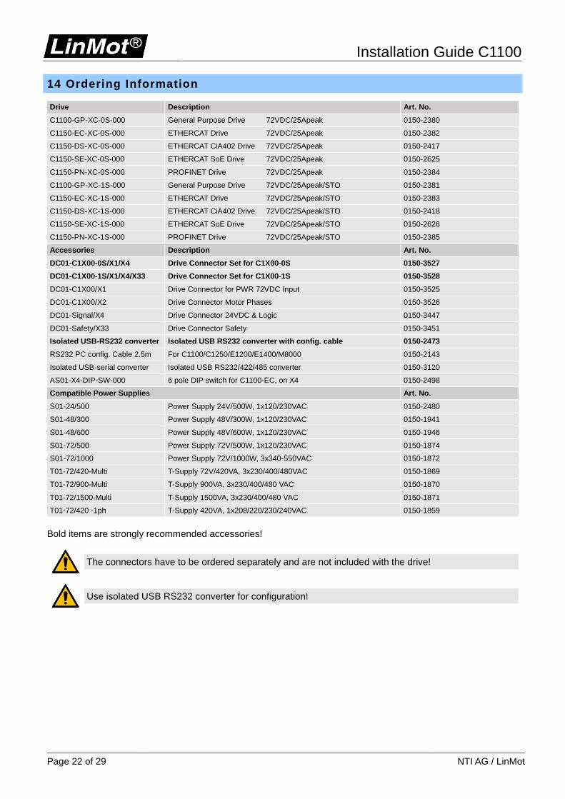
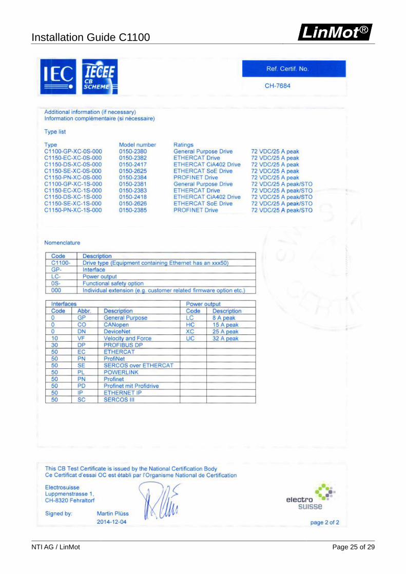
14 Ordering Information
Drive Description Art. No.
C1100-GP-XC-0S-000 General Purpose Drive 72VDC/25Apeak 0150-2380
C1150-EC-XC-0S-000 ETHERCAT Drive 72VDC/25Apeak 0150-2382
C1150-DS-XC-0S-000 ETHERCAT CiA402 Drive 72VDC/25Apeak 0150-2417
C1150-SE-XC-0S-000 ETHERCAT SoE Drive 72VDC/25Apeak 0150-2625
C1150-PN-XC-0S-000 PROFINET Drive 72VDC/25Apeak 0150-2384
C1100-GP-XC-1S-000 General Purpose Drive 72VDC/25Apeak/STO 0150-2381
C1150-EC-XC-1S-000 ETHERCAT Drive 72VDC/25Apeak/STO 0150-2383
C1150-DS-XC-1S-000 ETHERCAT CiA402 Drive 72VDC/25Apeak/STO 0150-2418
C1150-SE-XC-1S-000 ETHERCAT SoE Drive 72VDC/25Apeak/STO 0150-2626
C1150-PN-XC-1S-000 PROFINET Drive 72VDC/25Apeak/STO 0150-2385
Accessories Description Art. No.
DC01-C1X00-0S/X1/X4 Drive Connector Set for C1X00-0S 0150-3527
DC01-C1X00-1S/X1/X4/X33 Drive Connector Set for C1X00-1S 0150-3528
DC01-C1X00/X1 Drive Connector for PWR 72VDC Input 0150-3525
DC01-C1X00/X2 Drive Connector Motor Phases 0150-3526
DC01-Signal/X4 Drive Connector 24VDC & Logic 0150-3447
DC01-Safety/X33 Drive Connector Safety 0150-3451
Isolated USB-RS232 converter Isolated USB RS232 converter with config. cable 0150-2473
RS232 PC config. Cable 2.5m For C1100/C1250/E1200/E1400/M8000 0150-2143
Isolated USB-serial converter Isolated USB RS232/422/485 converter 0150-3120
AS01-X4-DIP-SW-000 6 pole DIP switch for C1100-EC, on X4 0150-2498
Compatible Power Supplies Art. No.
S01-24/500 Power Supply 24V/500W, 1x120/230VAC 0150-2480
S01-48/300 Power Supply 48V/300W, 1x120/230VAC 0150-1941
S01-48/600 Power Supply 48V/600W, 1x120/230VAC 0150-1946
S01-72/500 Power Supply 72V/500W, 1x120/230VAC 0150-1874
S01-72/1000 Power Supply 72V/1000W, 3x340-550VAC 0150-1872
T01-72/420-Multi T-Supply 72V/420VA, 3x230/400/480VAC 0150-1869
T01-72/900-Multi T-Supply 900VA, 3x230/400/480 VAC 0150-1870
T01-72/1500-Multi T-Supply 1500VA, 3x230/400/480 VAC 0150-1871
T01-72/420 -1ph T-Supply 420VA, 1x208/220/230/240VAC 0150-1859
Bold items are strongly recommended accessories!
The connectors have to be ordered separately and are not included with the drive!
Use isolated USB RS232 converter for configuration!
Installation Guide C1100
NTI AG / LinMot Page 23 of 29
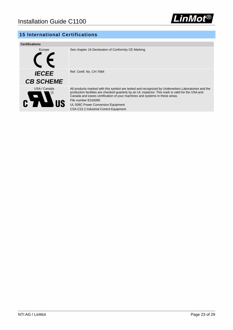
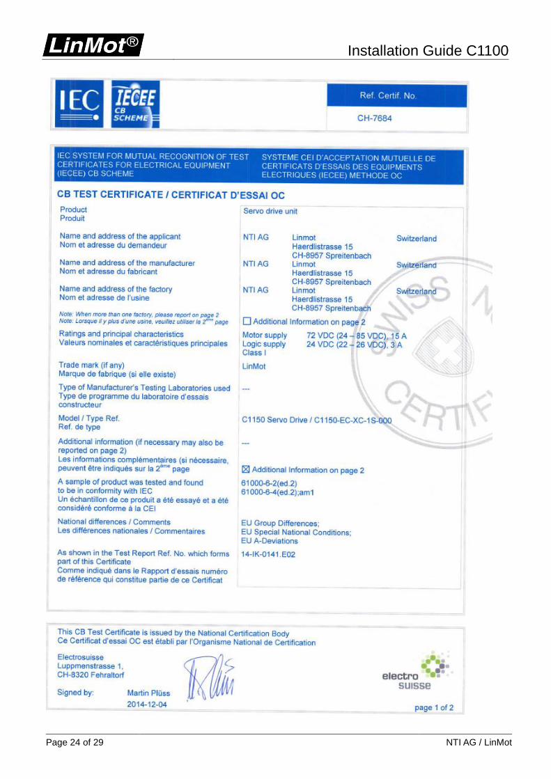
15 International Certifications
Certifications
Europe
See chapter 16 Declaration of Conformity CE-Marking
IECEE
CB SCHEME
Ref. Certif. No. CH-7684
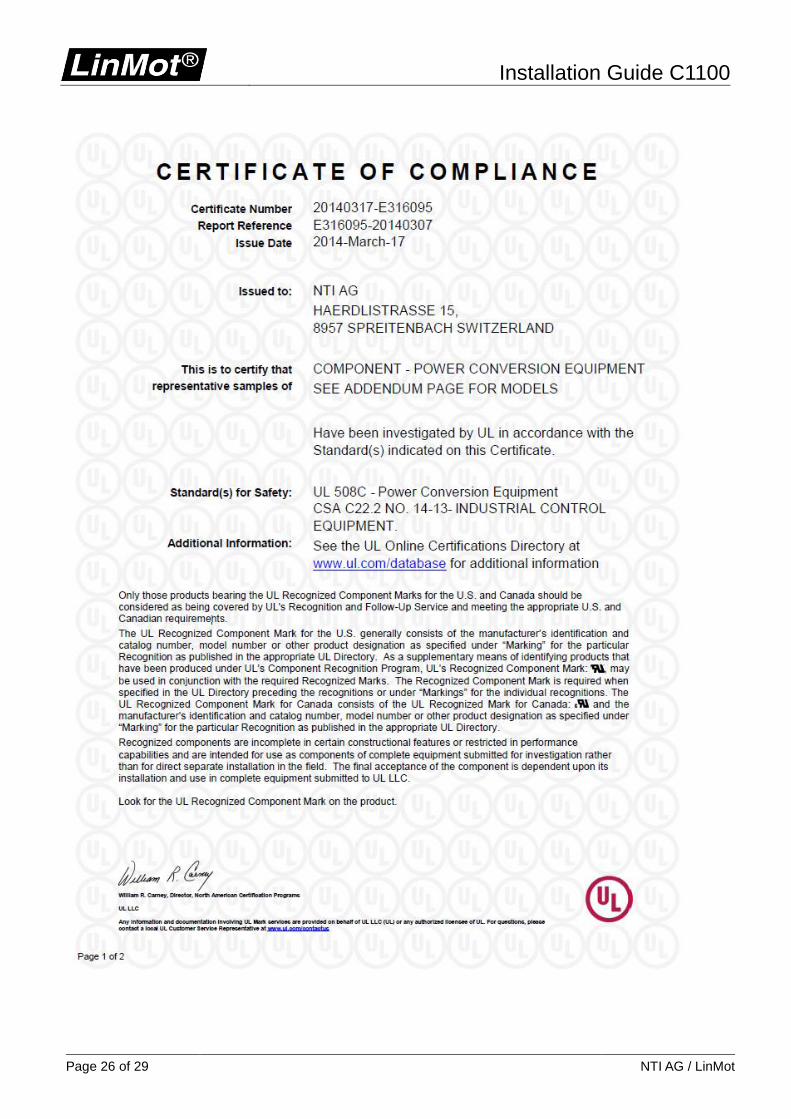
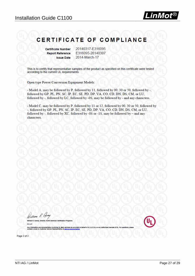
USA / Canada
All products marked with this symbol are tested and recognized by Underwriters Laboratories and the production facilities are checked quarterly by an UL inspector. This mark is valid for the USA and Canada and eases certification of your machines and systems in these areas.
File number E316095
UL 508C Power Conversion Equipment
CSA C22.2 Industrial Control Equipment
Installation Guide C1100
Page 24 of 29 NTI AG / LinMot
Installation Guide C1100
NTI AG / LinMot Page 25 of 29
Installation Guide C1100
Page 26 of 29 NTI AG / LinMot
Installation Guide C1100
NTI AG / LinMot Page 27 of 29
Installation Guide C1100
Page 28 of 29 NTI AG / LinMot
16 Declaration of Conformity CE-Marking
NTI AG / LinMot ® Bodenaeckerstrasse 2 8957 Spreitenbach Switzerland Tel.: +41 (0)56 419 91 91 Fax: +41 (0)56 419 91 92 declares under sole responsibility the compliance of the products:
Drives of the Series C11x0-xx-XC-xS-xxx with the EMC Directive 2014/30/EU. Applied harmonized standards:
EN 61000-6-2: 2005 (Immunity for industrial environments) EN 61000-6-4: 2007 (Emission for industrial environments) EN 61326-3-1: 2008 (Functional safety)
According to the EMC directive, the listed devices are not independently operable products. Compliance of the directive requires the correct installation of the product, the observance of specific installation guides and product documentation. This was tested on specific system configurations. The safety instructions of the manuals are to be considered. These products are intended for installation in machines. Operation is prohibited until it has been determined that the machines in which these products are to be installed, conforms to the above mentioned EC directive. The product must be mounted and used in strict accordance with the installation instructions contained within the installation guide, a copy of which may be obtained from NTI AG. Company: NTI AG Spreitenbach, 11.04.2016
---------------------------------------------------- Dr. Ronald Rohner / CEO NTI AG
Installation Guide C1100
NTI AG / LinMot Page 29 of 29
Contact & Support
SCHWEIZ NTI AG Bodenaeckerstrasse 2 CH-8957 Spreitenbach Sales and Administration: +41-(0)56-419 91 91 [email protected] Tech. Support: +41-(0)56-544 71 00 [email protected] http://www.linmot.com/support Tech. Support (Skype): skype:support.linmot Fax: +41-(0)56-419 91 92 Web: http://www.linmot.com/
USA LinMot USA Inc. 204 E Morrissey Dr. Elkhorn, WI 53121 USA Sales and Administration: 877-546-3270 262-743-2555 Tech. Support: 877-804-0718 262-743-1284 [email protected] Fax: 800-463-8708 262-723-6688 E-Mail: [email protected] Web: http://www.linmot-usa.com/
Please visit http://www.linmot.com/contact to find the distribution close to you. Smart solutions are…