Embed Size (px)
Citation preview

C172S Nav IIITraining Manual
Crosswinds Aviation
1st Edition

Aircraft Systems 3 .....................................................................................................................Engine 3 ..............................................................................................................................................................................................................Oil 3 .....................................................................................................................................................................................................................Propeller 3 ..........................................................................................................................................................................................................Landing Gear 4 ..................................................................................................................................................................................................Brakes 4 ..............................................................................................................................................................................................................Flaps 4 ................................................................................................................................................................................................................Pitot static system and instruments. 4 ..............................................................................................................................................................Stall warning horn. 4 .........................................................................................................................................................................................Fuel System. 5 .....................................................................................................................................................................................................Electrical System. 6 ............................................................................................................................................................................................Ignition System. 7 .............................................................................................................................................................................................. G1000 System (and other avionics). 7 .............................................................................................................................................................
Performance, Weight & Balance 10 ..........................................................................................Cessna 172s V speeds. 10 ....................................................................................................................................................................................Weight and Balance. 10 .....................................................................................................................................................................................
C172S Procedures guide 11 ........................................................................................................C172s Standard operaton procedures (SOP’s). 11 .............................................................................................................................................
Take off Procedures. 13 .............................................................................................................Normal Takeoff (Flaps 0°) 13 ...........................................................................................................................................................................Short field Takeoff (Flaps 10°) 14 ......................................................................................................................................................................Soft field Takeoff (Flaps 10°) 15 .........................................................................................................................................................................
Landing Procedures. 16 .............................................................................................................VFR Landing briefing procedure. 16 .................................................................................................................................................................Before landing checklist. 16 ...............................................................................................................................................................................Normal Landing procedure (Flaps 20°-FULL) 17 ............................................................................................................................................Maneuver standards: +10-5 1.3x Vso approach, touchdown within 400’ of selected point. 17 .....................................................................Short field Landing procedure (Flaps FULL) 18 ..............................................................................................................................................Maneuver standards: +10-5 1.3x Vso approach, touchdown within 200 feet of selected point. 18 ...............................................................Soft field Landing procedure (Flaps FULL) 19 .................................................................................................................................................Maneuver standards: +10-5 1.3x Vso approach, touchdown with minimum sink rate. 19 ...........................................................................Power off 180 procedure (Flaps as required) 20 ..............................................................................................................................................Maneuver standards: N/A 20 ...........................................................................................................................................................................Forward slips to land 21 ....................................................................................................................................................................................Maneuver standards: touchdown within 400 feet of selected point. 21 .........................................................................................................
Emergency Procedures. 22 .......................................................................................................Emergency Descent 22 .......................................................................................................................................................................................
Performance Maneuvers. 22 .....................................................................................................Steep Turns 22 ....................................................................................................................................................................................................Slow Flight 23 .....................................................................................................................................................................................................Power On Stalls 23 .............................................................................................................................................................................................Power Off Stalls 24 .............................................................................................................................................................................................
Ground Reference Maneuvers. 25 ............................................................................................Rectangular Course 25 ......................................................................................................................................................................................Turns around a point 26 ....................................................................................................................................................................................S-Turns 27 ..........................................................................................................................................................................................................
C172S Quiz Questions. 29.........................................................................................................

Aircraft Systems Engine The C172S is equipped with a Lycoming, 4-cylinder, IO-360-L2A (Fuel injected, opposed, 360 cubic inch displacement) engine rated at 180 horsepower at 2700 RPM. The engine is direct drive (crankshaft connected directly to the propeller), horizontally opposed (pistons oppose each other), piston driven, fuel injected and normally aspirated (no turbo or supercharging). Engine ignition is provided through the use of engine-driven magnetos, which are independent of the aircraft's electrical system and each other and utilize impulse coupling. The induction system has a spring loaded alternate air door inside the cowling (behind the filter on the left hand side) that will automatically open if the air filter becomes plugged.
L Lycoming IO 360 H Horizontally Opposed 4 cylinder A Air Cooled N Normally Aspirated D Direct Drive
Oil The Acceptable range for oil in the C172S is 5-8 quarts. Never depart with the oil indicating below 5 quarts. Use only oil approved by the flight school, never use open oil containers and risk contamination. The engine has a full pressure wet sump type lubrication system. Oil is drawn from the sump through an oil suction strainer screen into the engine-driven oil pump. From the pump, oil is routed to a bypass valve. If the oil is cold, the bypass valve allows the oil to bypass the oil cooler and go directly from the pump to the full flow oil filter. If the oil is hot, the bypass valve routes the oil out of the accessory housing and into a flexible hose leading to the oil cooler on the right, rear engine baffle. Pressure oil from the cooler returns to the accessory housing where it passes through the full flow oil filter. The filter oil then enters a pressure relief valve which regulates engine oil pressure by allowing excessive oil to return to the sump while the balance of the oil is circulated to various engine parts for lubrication. Residual oil is returned to the sump by gravity flow. An oil dipstick indicates the level of oil in the tank. The dipstick is marked for US quarts.
Propeller The C172S is equipped with a two-bladed, fixed pitch, one piece forged aluminum alloy propellor which is anodized to retard corrosion. The propellor is 76 inches in diameter.

Landing Gear The C172S is equipped with fixed tricycle type landing gear. The main gear is mounted to tubalar spring struts mounted to the fuselage below the wings. The nose wheel consists of an air oil type strut and is steerable with linkage to the rudder pedals.
Brakes The airplane has a single-disc, hydraulically actuated brake on each main landing gear wheel. Each brake is connected, by a hydraulic line, to a master cylinder attached to each of the pilot's rudder pedals. The brakes are operated by applying pressure to the top of either the left (pilot's) or right (copilot's) set of rudder pedals, which are interconnected. When the airplane is parked, both main wheel brakes may be set by utilizing the parking brake which is operated by a handle under the left side of the instrument panel. To apply the parking brake, set the brakes with the rudder pedals, pull the handle aft, and rotate it 90° down.
Flaps The single-slot type wing flaps, are extended or retracted by positioning the wing flap switch lever on the instrument panel to the desired flap deflection position. The switch lever is moved up or down in a slotted panel that provides mechanical stops at the 10°, 20° and 30° positions. To change flap setting, the flap lever is moved to the right to clear mechanical stops at the 10° and 20° positions. A scale and pointer to the left of the flap switch indicates flap travel in degrees. The wing flap system circuit is protected by a 10- ampere circuit breaker, labeled FLAP, on the left side of the control panel.
Pitot static system and instruments. The pitot-static system uses a heated total pressure (pitot) head mounted on the lower surface of the left wing, external static ports mounted on the left side of the forward fuselage and associated plumbing to connect the GDC 74A Air Data Computer and the conventional pitot-static instruments to the sources. The heated pitot system uses an electrical heating element built in the body of the pitot head. The PITOT HEAT control switch is found on the switch panel below the lower LH corner of the PFD. The PITOT HEAT circuit breaker (10 A) is found on the circuit breaker panel at the lower LH side of the pilot panel. A static pressure alternate source valve (ALT STATIC AIR) is located next to the throttle control. The ALT STATIC AIR valve provides static pressure from inside the cabin if the external static pressure source becomes blocked. If erroneous instrument readings are suspected due to water or ice in the pressure line going to the standard external static pressure source, the alternate static source valve should be pulled on. Pressures within the cabin will vary with open heaters/vents and windows.
Stall warning horn. The airplane is equipped with a pneumatic type stall warning system consisting of an inlet in the leading edge of the left wing, an air-operated horn near the upper left corner of the

windshield, and associated plumbing. As the airplane approaches a stall, the low pressure on the upper surface of the wings moves forward around the leading edge of the wings. This low pressure creates a differential pressure in the stall warning system which draws air through the warning horn, resulting in an audible warning at 5 to 10 knots above stall in all flight conditions.
Fuel System. Each C172S fuel tank holds 28 gallons of fuel, 26.5 is useable (56 gal total, 53 useable). The tanks can also be fueled to the “bottom of the filler neck (“tabs”)” which is 17.5 gallons useable per side, 35 useable gallons total. The aircraft should be serviced with blue, 100LL fuel. The fuel should be checked for the correct fuel, contaminants, and water via the 13 fuel sumps located on the aircraft (5 each wing, 3 under the belly going to the reservoir tank, selector drain, and strainer).
Fuel flows by gravity from the two wing tanks to a three-position selector valve, labeled BOTH, RIGHT and LEFT and on to the reservoir tank. From the reservoir tank fuel flows through the auxiliary fuel pump, past the fuel shutoff valve, through the fuel strainer to an engine driven fuel pump. From the engine-driven fuel pump, fuel is delivered to the fuel/air control unit, where it is metered and directed to a fuel distribution valve (manifold) which distributes it to each cylinder. Fuel flow into each cylinder is continuous, and flow rate is determined by the amount of air passing through the fuel/air control unit. It is not necessary to operate the auxiliary fuel pump during normal takeoff and landing, since gravity and the engine-driven pump will supply adequate fuel flow.
The auxiliary fuel pump is used for engine priming, vapor suppression, and mechanical pump failures.
Fuel system venting is essential to system operation. Blockage of the system will result in decreasing fuel flow and eventual engine stoppage. The interconnected tanks vent thru the left fuel tank vent line, which is equipped with a check valve, that protrudes from the bottom surface of the left wing near the wing strut. Both fuel filler caps are also vented.
Instructors Note:Never dump sumped fuel back into the aircraft unless your strainer has been cleaned prior to taking a fuel sample.

Electrical System. The airplane is equipped with a 28-volt direct current (DC) electrical system consisting of a belt-driven 60-ampere alternator and a 24- volt main storage battery. Individual system circuit breakers are found on the circuit breaker panel below the pilot's control wheel. All circuit breakers are "pullable" for electrical load management. The G1000 equipment has non-field replaceable fuses (it is possible to blow an inline fuse and lose avionics in flight that can only be replaced by maintenance. The storage battery is located inside the engine cowling on the left firewall. The alternator and battery are controlled through the MASTER switch (ALT and BAT) found near the top of the pilot's switch panel. Power is supplied to most electrical circuits through two primary buses (ELECTRICAL BUS 1 and ELECTRICAL BUS 2), with an Essential Bus and a crossfeed bus connected between the two primary buses to support essential equipment. The avionics switches supply power to the avionics busses. The system is equipped with a secondary or "standby" battery located between the firewall and the instrument panel. The STBY BATT switch controls power to or from the standby battery. The standby battery is available to supply power to the Essential Bus in the event that alternator and main battery power sources have both failed.

If the alternator system fails, the MASTER switch may be set to the OFF position to preserve Main Battery capacity for later in the flight. With the MASTER switch OFF and the STBY BATT switch in the ARM position, the standby battery will power the Essential Bus for a limited time. Time remaining may be estimated by monitoring Essential Bus Voltage. At 20 Volts, the standby battery has little or no capacity remaining.
The aircraft’s electrical system status is displayed to the crew via the voltmeter, ammeter, and annunciators. Normal bus voltages with the alternator operating shall be about 28 volts. When the voltage for either Main or Essential is at or below 24.5 volts, the numeric value and VOLTS text turns red along with the "LOW VOLTS" annunciation. This is an indication that the alternator is not supplying all the power that is required by the aircraft. (Indicated voltages between 24.5 and 28 volts may occur during low engine RPM conditions).
Electric current (AMPS) indication for both the main and Standby batteries is provided at the bottom of the EIS ENGINE or SYSTEM pages, labeled "M BATT S". Main battery current is displayed below the "M". Standby battery current is displayed below the "S". A positive current value (shown in white) indicates that the battery is charging. A negative current value (shown in amber) indicates that the battery is discharging. In the event the alternator is not functioning or the electrical load exceeds the output of the alternator, the main battery ammeter indicates the main battery discharge rate.
In the event that Standby battery discharge is required, normal discharge should be less than 4 Amps. After engine start, with the STBY BATT switch in the ARM position, the Standby Battery ammeter should indicate a charge showing correct charging of Standby Battery System.
Ignition System. The engine is provided with two independent ignition systems. The two engine driven magnetos are independent from the power supply system, and are in operation as soon as the propeller is turning and the ignition switch is not off. This ensures safe engine operation even in case of an electrical power failure. When the MAGNETOS switch is rotated to the spring loaded START position, (with the master switch in the ON position), the starter contactor is closed and the starter, now energized, will crank the engine. When the switch is released, it will automatically return to the BOTH position.
G1000 System (and other avionics). The C172S avionics include a G1000, KAP 140 autopilot, and standby airspeed, altimeter, and attitude indicators.The G1000 is comprised of several main components: Primary Flight Display (PFD, left) and Multi-Function Display (MFD, right) Audio panel (also supplies connection between PFD & MFD for revisionary mode)2 Avionics Units (each supplies both GPS and VHF information to G1000)

Attitude Heading Reference System (AHRS, sensors replace traditional gyros)Magnetometer (supplies heading information to AHRS, located in left wing)Air Data Computer (ADC, compiles info from pitot/static system and OAT)Engine Monitor (compiles engine info and sends it to avionics unit) Transponder (ADS-B transponder that is operated on PFD)XM data link (provides weather and radio data to MFD)The PFD shows primary flight information in place of traditional pitot- static and gyroscopic instruments, and also provides an HSI for navigation. A slip- skid indicator is located at the top of the attitude indicator. Step on the “brick” instead of the “ball”. Use the reference lines and the magenta line that appears above the heading indicator to identify a standard rate or half-standard rate turn. Outside air temperature (OAT) displays on PFD under the airspeed tape. Ground track can be identified on the heading indicator by a small magenta diamond near the lubber line (only visible when ground track is different than heading). The digital altitude and airspeed readouts are very sensitive and can cause some pilots to continuously make corrections for insignificant deviations.
The MFD displays a large scaleable, moving map that corresponds to the airplane’s current location. Data from other components of G1000 can be overlaid onto the MFD. The MFD is also the principle display of engine information. Revisionary mode places basic flight info on both PFD and MFD which allows for safe operation if a screen fails.


Performance, Weight & Balance Cessna 172s V speeds. Speeds listed below are in Knots Indicated Airspeed (KIAS).
Weight and Balance. Formulas
• Weight × Arm = Moment • Total Moment ÷ Total Weight = CG • Max Ramp Weight – Zero Fuel Weight = Usable Fuel Weight • Fuel Weight ÷ 6 = Fuel Gallons • 100 LL (Blue) Fuel Weighs 6 lbs./gal.; Oil Weighs 7.5 lbs./gal. • Unusable fuel and oil at full capacity are Included in Basic Empty Weight
Maximum Ramp Weight 2558lbsMaximum Take off weight weight 2550lbs
Speed KTS
Description Airspeed indicator markings
Vso 40 Stall speed in landing configuration
Vs 48 Stall speed with zero flaps Bottom of White Line
Vr 55 Rotation speed (start rotation) Bottom of Green Line
Vx 62 Best angle of climb
Vy 74 Best rate of climb
VG 68 Best glide speed
Vfe 110 Maximum flap 10 degrees speed
Vfe 85 Maximum flap 20-FULL degrees speed Top of White Line
Vno 129 Max Structural Cruising Speed Top of Green Line
Vne 163 Never exceed speed Red Line
Va 105 Maneuvering speed

Maximum weight in the baggage areas A and B combined: 120lbs (120lbs for area A, 50 lbs for area B)
C172S Procedures guide C172s Standard operaton procedures (SOP’s).
Passenger Briefing SAFETY 1. Safety Belt/Harness
Usage 2. Air vent operation
3. Fire Extinguisher Location/Usage
4. Emergency exits, canopy usage
5. Traffic and Talking 6. Your questions?
Flight instrument check • Airspeed - reading zero. • Attitude indicator - blue over brown within 5 degrees in 5 minutes. • Altimeters - set & Crosscheck (Current Baro setting) within 75 feet of field elevation. • VSI - reading zero (up to 100’ deviations are approved but must be taken into account
during flight) • Turn coordinator - Wings level ball in the center • HSI/DG aligned with the compass. • Compass no cracks no leaks no bubbles, deviation card present.
Flight instrument check during taxi• Turn coordinator indicating a turn • Inclinometer (Ball) indicating a skid • Compass swinging freely • HSI/DG turning freely.
Pre-Takeoff Briefing Engine failure or abnormality prior to rotation: • Abort takeoff – throttle immediately closed Brake as required stop straight ahead • If not enough runway to stop: Mixture to cutoff
Fuel selector, magnetos, and battery master off avoid obstacles Engine failure after rotation with sufficient runway remaining for a complete stop:
• Throttle immediately closed • Land straight ahead, brake as required
Engine failure after rotation with no runway remaining:• Maintain control/pitch for best glide • Only shallow turns to avoid obstacles • Flaps as necessary for safe touchdown • Throttle closed

• Mixture to cutoff • Fuel selector, magnetos, and battery master off• Touchdown at lowest speed possible

Take off Procedures.
Normal Takeoff (Flaps 0°) Maneuver standards: Vy +10-5kts to a safe altitude.
1. Line up on centerline positioning controls for wind 2. Smoothly apply full power 3. Check engine gauges 4. Right rudder as required for turning tendencies 5. “Airspeed Alive” 6. Start smooth rotation at 55 KIAS 7. Accelerate to 74 KIAS (VY) 8. “After Takeoff Checklist” 1,000' AGL
�
1. Line up on centerline 2. Smoothly apply full power4. check guages5. Right rudder as required
Airspeed Alive”Start smoth rotation at 55 KIAS
Accelerate to 74 KIAS (VY)
“After Takeoff Checklist” out of 1,000' AGL
Normal Takeoff (Flaps 0)
500’ Flaps up
Short field Takeoff (Flaps 10°) Maneuver standards: Vx +10-5kts over obstacle then Vy +10-5kts
1. Select flaps 10° 2. Line up on centerline positioning controls for wind 3. Hold brakes 4. Increase throttle to Full 5. Check engine gauges 6. Release brakes 7. “Airspeed Alive” 8. Briskly rotate at 51 KIAS (or as calculated with performance charts) 9. Accelerate to 56 KIAS (Vx) (or as calculated with performance charts) 10. Clear of obstacles, flaps cruise. 11.Accelerate to 74 KIAS (VY) 12.“After Takeoff Checklist” out of 1,000' AGL
�
1. Line up on centerline 2. Hold brakes3. Throttle Full4. Check guages6. Release brakes
Airspeed Alive” Briskly rotateat 51 KIAS
Accelerate to 56 KIAS (Vx)
“After Takeoff Checklist” out of 1,000' AGL
Short Field Takeoff (Flaps 10°)
500’ Flaps up

Soft field Takeoff (Flaps 10°) Maneuver standards: Maintain Vx or Vy +10-5kts
1. Flaps 10° 2. Roll onto runway with full aft yoke – minimum braking – do not stop 3. Smoothly apply full power holding full AFT on the yoke - check engine gauges 4. As nose lifts off , ease back pressure (nose wheel must remain off ground) 5. Lift off at lowest possible airspeed – remain in ground effect 6. In ground effect – accelerate to 62 KIAS – begin climb 7. Clear of obstacles, flaps Cruise. 8. Accelerate to 74 KIAS (VY) 9. “After Takeoff Checklist” out of 1,000' AGL
!
1. Roll onto runway with full aft yoke 2. Smoothly apply full power
Airspeed Alive”Start smooth rotation at 58 KIAS
Accelerate to 62KIAS in ground effect
“After Takeoff Checklist” out of 1,000' AGL
Soft Field Takeoff (Flaps 10)
500’ flaps upLift off at lowest possible airspeed remain in ground
Accelerate to 74 KIAS (Vy)

Landing Procedures. VFR Landing briefing procedure. Announce verbally1. Type of Approach & Landing Runway
2. Aiming & Touchdown Point
3. Wind Direction & Speed Pattern Altitude
4. Go-Around Criteria & Plan
Example: “This will be a normal flaps full landing on runway 13 with an intended touchdown point of the one thousand foot markers, aiming point will be 3 stripes prior, we can expect a left crosswind of 5 knots”.
Stabilized Approach Definition: A stabilized approach is one in which the pilot establishes and maintains a constant angle glide-path towards a predetermined point on the landing runway. It is based on the pilot’s judgment of certain visual cues, and depends on a constant final descent airspeed and configuration (FAA-H-8083- 3A, p.8-7).
Approach Gust factors. Slightly higher approach speeds should be used under turbulent or gusty wind conditions. Add 1⁄2 the gust factor to the normal approach speed. For example, if the wind is reported 8 gusting to 18 knots, the gust factor is 10 knots. Add 1⁄2 the gust factor, 5 knots in this example, to the normal approach speed.
Before landing checklist. This is a memory item that needs to get memorized prior to the second flightAnnounce verbally
1. Seat belts - fastened2. Fuel selector - both3. Mixture set4. Fuel pump on5. Gen/Bat master - ON6. Mags - BOTH7. Lights - as required8. Flaps - as required

Normal Landing procedure (Flaps 20°-FULL) Maneuver standards: +10-5 1.3x Vso approach, touchdown within 400’ of selected point.
1. Complete the “Approach Checklist” before entering the airport; devote full attention to aircraft control and traffic avoidance.
2. Slow to 90 KIAS prior to entering downwind or traffic pattern and complete the before landing checklist.
3. Enter traffic pattern at published TPA (typically 1,000' AGL). 4. Complete the “VFR Landing Brief” when established on the downwind. 5. When abeam touchdown point, on extended base, or on extended final (when ready to
descend out of pattern altitude) Reduce power to 1700 and select flaps 10°. 6. Descend out of TPA at 90 KIAS. 7. Turn base approx. 45 degrees from touchdown point, slow to 80 KIAS and select flaps 20°. 8. Maintain 65 KIAS on final (select flaps full if desired). 9. Smoothly reduce power when approaching aiming point.
�
Normal landing (Flaps 20)
Abeam touchdown point, power 1700RPM Flaps 10 Degrees
90kts on downwind Descend out of TPA at 80kts
Final 65kts
Slowing to 90ktsApprox 45 degres from touchdown point turn base
400’ stabalized continuing
If aircraft is not stabalizedinitiate an imidiate go around
Base
Leg
Fl
aps 2
0 D
egre
es
70Kt
s

Short field Landing procedure (Flaps FULL) Maneuver standards: +10-5 1.3x Vso approach, touchdown within 200 feet of selected point.
1. Complete the “Approach Checklist” before entering the airport; devote full attention to aircraft control and traffic avoidance.
2. Slow to 90 KIAS prior to entering downwind or traffic pattern and complete the before landing checklist.
3. Enter traffic pattern at published TPA (typically 1,000' AGL). 4. Complete the “VFR Landing Brief” when established on the downwind. 5. When abeam touchdown point, on extended base, or on extended final (when ready to
descend out of pattern altitude) Reduce power to 1700 and select flaps 10°. 6. Descend out of TPA at 90 KIAS. 7. Turn base approx. 45 degrees from touchdown point, slow to 80 KIAS and select flaps 20°. 8. Select flaps FULL and maintain 61 KIAS on final. 9. Smoothly reduce power when approaching aiming point touch down with minimum floating 10. hold the stick full AFT, Announce “simulate max braking”. (DO NOT SKID THE TIRES)
�
Short field landing (Flaps Full)
90kts on downwind Descend out of TPA at 80kts
Final flaps full 61Kts
Slowing to 90ktsApprox 45 degres from touchdown point turn base
400’ stabalized continuing
After touch down Announce simulating max braking.
If aircraft is not stabalizedinitiate an imidiate go around
Base
Leg
Fl
aps 2
0 70
Kts
Abeam Touchdown point, Power 1700RPM Flaps 10 Degrees

Soft field Landing procedure (Flaps FULL) Maneuver standards: +10-5 1.3x Vso approach, touchdown with minimum sink rate.
1. Complete the “Approach Checklist” before entering the airport; devote full attention to aircraft control and traffic avoidance.
2. Slow to 90 KIAS prior to entering downwind or traffic pattern and complete the before landing checklist.
3. Enter traffic pattern at published TPA (typically 1,000' AGL). 4. Complete the “VFR Landing Brief” when established on the downwind. 5. When abeam touchdown point, on extended base, or on extended final (when ready to
descend out of pattern altitude) Reduce power to 1700 and select flaps 10°. 6. Descend out of TPA at 90 KIAS. 7. Turn base approx. 45 degrees from touchdown point, slow to 80 KIAS and select flaps 20°. 8. Select flaps FULL and maintain 61 KIAS on final. 9. Smoothly reduce power to 1000RPM when approaching aiming point and touch down as
smoothly as possible. 10. Hold the yoke full AFT, to protect the nose gear.
!
Soft field landing (Flaps Full)
Descend out of TPA at 90kts
Approx 45 degres from touchdown point turn base
After touch down keep yoke full aft.
90kts on downwind Descend out of TPA at 80kts
Slowing to 90kts
If aircraft is not stabalizedinitiate an imidiate go around
400’ stabalized continuing
Final flaps full 61Kts
Base
Leg
Fl
aps 2
0 70
Kts
Abeam Touchdown point, Power 1700RPM Flaps 10 Degrees

Power off 180 procedure (Flaps as required) Maneuver standards: N/A
1. Complete the “Approach Checklist” before entering the airport; devote full attention to aircraft control and traffic avoidance.
2. Slow to 90 KIAS prior to entering downwind or traffic pattern. 3. Enter traffic pattern at published TPA (typically 1,000' AGL). 4. Complete the “VFR Landing brief” when established on the downwind. 5. When abeam touchdown point, power to idle. 6. Adjust pitch to maintain appropriate glide speed. 7. Plan and maneuver to execute a safe approach and landing 8. Use flaps 0-FULL as necessary. 9. Touchdown in normal landing attitude, at or within 200 feet
beyond the specified landing point. 10. After nose wheel is down gently apply brakes.
�
Power off 180
Abeam Touchdown point Power idle.
90kts on downwind Descend out of TPA at VG
Best glide 68kts-Flaps as Req
Slowing to 90kts
400’ stabalized continuing
If aircraft is not stabalizedinitiate an imidiate go around
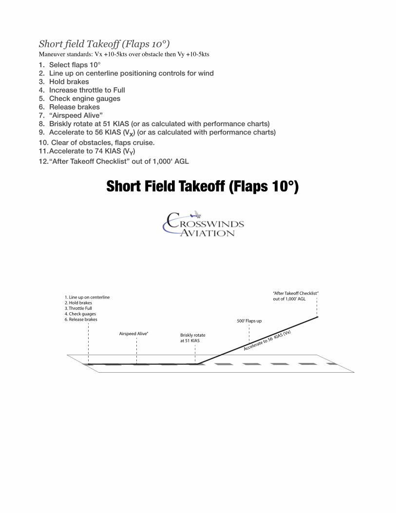
Forward slips to land Maneuver standards: touchdown within 400 feet of selected point.
1. Complete the “Approach Checklist” before entering the airport; devote full attention to aircraft control and traffic avoidance.
2. Slow to 90 KIAS prior to entering downwind or traffic pattern and complete the before landing checklist.
3. Enter traffic pattern at published TPA (typically 1,000' AGL). 4. Complete the “VFR Landing Brief” when established on the downwind. 5. When abeam touchdown point, on extended base, or on extended final (when ready to
descend out of pattern altitude) Reduce power to 1700 and select flaps 10°. 6. Descend out of TPA at 90 KIAS. 7. Turn base approx. 45 degrees from touchdown point, slow to 80 KIAS and select flaps 20°. 8. On final, select flaps full and reduce power to idle 9. Simultaneously apply aileron into the wind with opposite full rudder 10. Rudder will control the amount of slip while aileron will keep aircraft on centerline. 11. Relieve control pressures as aircraft approaches a normal approach height 12. Resume normal landing procedures.
Slips are used for emergency situations only and should not be used to fix an un stabilized approach to landing.

Emergency Procedures. Emergency Descent 1. Throttle closed and mixture rich for the practice manuever (SIMULATE emergency checklist) 2. Get air speed above 100kts 3. Roll into a 45 degree bank, allowing the nose to drop and initiating a descent 4. Allow the airspeed to stabilize at Vno execute medium bank 90 degree turns. 5. Stop the emergency descent no lower than 1000’ AGL and prepare for landing.
Performance Maneuvers. Steep Turns Maneuver standards: ALT +/- 100’ Bank 45°+/-5° HDG +/-10° Speed +/-10ktsNOTE: Minimum safe altitude for this maneuver is 1500’ AGL. Crosswinds Aviation requires a minimum altitude of 3,500’ AGL. Establish Cruise and complete the Pre-maneuver Check. 1. Perform clearing turns 2. Set power to 2200 RPM 3. Starting speed 90-95 KIAS 4. Select a heading or reference point for rollout 5. From straight and level coordinate aileron and rudder to roll into a 45 o bank. 6. Add a small amount of power (100 – 200 RPM) as you roll through 30 o of bank 7. Maintain altitude and airspeed 8. Reference the horizon to assist with maintaining altitude and bank angle 9. Maintain bank angle with aileron, coordinate with rudder 10.Apply opposite aileron to counter over-banking tendency 11.Anticipate rollout by half the angle of bank (20 - 25 degrees) 12.Roll out using coordinated aileron and rudder pressures to straight and level flight 13.Repeat in the other direction 14.Exit at the point of entry at the same altitude and airspeed at which the maneuver was started 15.Adjust power to 90-95 KIAS
NOTE: The primary reason for making an emergency descent in a non-pressurized aircraft would be engine or cabin fire. While making the descent, the pilot should make an effort to perform the appropriate non-normal checklist. (Flap settings and descent speeds may change Ask your IP)

Slow Flight Maneuver standards: ALT +/- 100’ Bank 5°+/-5° HDG +/-10° Speed +10 -0ktsNOTE: Minimum safe altitude for this maneuver is 1500’ AGL, Crosswinds Aviation requires a minimum altitude of 3,500’ AGL.Slow flight is performed in the landing Configuration1. Perform clearing turns 2. Reduce throttle to 1700 RPM 3. As airspeed decreases a gradual increase in back elevator pressure will be required to
maintain altitude 4. Trim off control pressure as necessary.5. Below 85 KIAS (White Arc) 6. Flaps 10°– watch for ballooning tendency, increase forward elevator as necessary to maintain
altitude. 7. Flaps 20° 8. Flaps FULL 9. Trim to relieve control pressures 10.Maintain altitude and heading 11.Slow to an airspeed that is 5 to 10 knots above published Vso. 12.Maintain directional control using outside visual references and inside instrument references 13.Practice gentle climbs, descents, and turns at constant airspeed Recovery procedure 1. smoothly apply full power 2. Lower nose at a rate that will maintain altitude (0 VSI) 3. Retract flaps to 20° 4. Maintain level altitude (0 VSI) 5. Retract flaps to 10° 6. Maintain level altitude (0 VSI) 7. Approaching 65 KIAS, retract flaps to 0° 8. Approaching cruise airspeed, trim as necessary 9. Complete CRUISE checklist
Power On Stalls Maneuver standards: ALT +/- 100’ Bank 45°+/-5° HDG +/-10° Speed +/-10ktsNOTE: Minimum safe altitude for this maneuver is 1500’ AGL, Crosswinds Aviation requires a minimum altitude of 3,500’ AGL.Power on stalls are performed in the Take off Configuration1. Perform clearing turns 2. Set power to 1700 RPM 3. Below 110 KIAS 4. Flaps 10° (or flaps up)

5. Slow to VR (55 KIAS) 6. Add 10° of bank if performing turning stalls 7. Simultaneously pitch up and increase power to 2200 RPM 8. Maintain coordination at all times 9. Recognize and announce symptoms of approaching stall 10.Sight, sound, feel 11.Stall warning horn activates 12.Aerodynamic buffeting Recovery procedure 1. Reduce the Angle of Attack (AOA) 2. Release enough back pressure to break the stall 3. Level wings 4. Apply full power 5. Establish a shallow climb (100 – 200 FPM) 6. At positive rate of climb and approaching 62 KIAS 7. Retract flaps to 0 (when obstacle cleared) 8. Climb at 74 KIAS to initial altitude NOTE: This stall may not cause any loss of altitude. In this case, lower the nose and establish a pitch attitude for a stabilized shallow climb (100 – 200 fpm) and level off at a determined altitude.
Power Off Stalls Maneuver standards: ALT +/- 100’ Bank 45°+/-5° HDG +/-10° Speed +/-10ktsNOTE: Minimum safe altitude for this maneuver is 1500’ AGL, Crosswinds Aviation requires a minimum altitude of 3,500’ AGL. Power Off stalls are performed in the landing Configuration 1. Perform clearing turns 2. Reduce throttle to 1700 RPM 3. Below 110 KIAS Flaps 10° 4. Stabilize 5. Flaps 20°, then 30° below 85kts 6. Stabilize the aircraft in a descent at approach speed (65 KIAS) 7. After descending approx 200’, reduce power to idle (Not less than 1,000 RPM) 8. Simulate landing flare by raising the nose to the horizon. 9. maintain pitch by applying constant back pressure 10.Maintain coordination at all times 11.Recognize and announce symptoms of approaching stall 12.Sight, sound, feel 13.Stall warning horn activates 14.Aerodynamic buffeting
Recovery procedure 1. Reduce the Angle of Attack 2. Level the wings using coordinated rudder and aileron 3. Gradually apply full power 4. Stop Descent 5. Retract flaps to 20° 6. Establish a shallow climb (100 – 200 FPM) 7. At positive rate of climb and approaching 62 KIAS 8. Retract flaps to as necessary to 0°9. Climb at 74 KIAS to initial altitude
10.Complete both CLIMB and CRUISE checklists after leveling off Note: If engine appears to drop below 1,000 RPM, add throttle to ensure engine will not stop.
Ground Reference Maneuvers. NOTE: All ground reference maneuvers are performed at 1,000’ AGL, and are entered on a downwind leg simulating traffic pattern altitude and are performed in the “Clean” configuration. Before descending for the maneuver it is important to visually scan the area for obstructions and a safe landing spot incase an emergency landing is necessary.
Ground reference maneuvers are done in the clean configuration at 1000’ AGL and 90kts mimicking the traffic pattern. Clean Configuration Flaps - 0 Mixture - Full Rich Landing Light - ON PTS Requirements ALT +/- 100’ Speed +/- 10 kts Rectangular Course 1. Set power to maintain an airspeed of 90kts 2. Maneuver is performed 1,000 AGL 3. Enter the maneuver 45 to the downwind with the first circuit to the left Downwind 1. Roll wings level, parallel to the boundary 2. Maintain distance (about 1⁄2 mile) from boundary 3. At field boundary edge, turn first crosswind leg 4. Start with steep bank 5. Reduce bank angle gradually during the turn First Crosswind Leg (Crosswind) 1. Roll out, wings level crabbing toward the boundary 2. Manage crab angle to maintain 1⁄2 mile distance from boundary 3. At field boundary edge, turn upwind 4. Start with medium bank 5. Reduce bank angle gradually during the turn as ground speed decreases Upwind 6. Roll wings level, parallel to the boundary 7. At field boundary edge, turn second crosswind leg 8. Start with shallow bank 9. Increase bank angle gradually during the turn as ground speed increases Second Crosswind Leg (Base) 1. Roll out wings level, crabbing away from the boundary 2. Manage crab angle to maintain 1⁄2 mile distance from boundary 3. At field boundary edge, turn downwind 4. Start with moderate bank Increase bank angle gradually during the turn as ground speed
increases
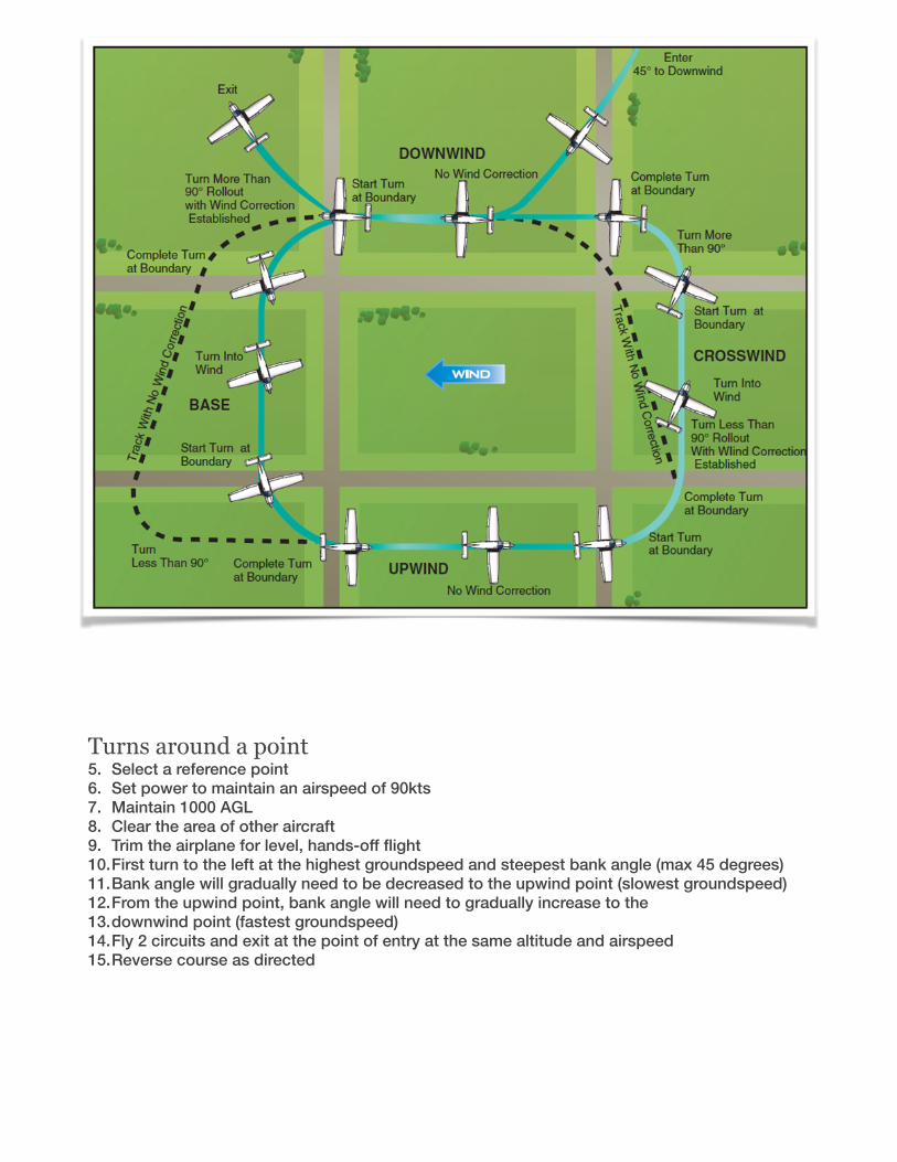
Turns around a point5. Select a reference point 6. Set power to maintain an airspeed of 90kts7. Maintain 1000 AGL8. Clear the area of other aircraft 9. Trim the airplane for level, hands-off flight10.First turn to the left at the highest groundspeed and steepest bank angle (max 45 degrees) 11.Bank angle will gradually need to be decreased to the upwind point (slowest groundspeed) 12.From the upwind point, bank angle will need to gradually increase to the 13.downwind point (fastest groundspeed) 14.Fly 2 circuits and exit at the point of entry at the same altitude and airspeed 15.Reverse course as directed

S-Turns 1. Select a line feature that lies crosswind 2. Set power to maintain an airspeed of 90kts3. Maintain 1000 AGL4. Trim the airplane for level, hands-off flight 5. Approach the line feature downwind 6. Cross the line feature wings level 7. Initial turn is to the left at the fastest groundspeed and steepest bank angle
(not to exceed 30 degrees) 8. Directly crosswind; moderate bank angle and decrease as the airplane turns upwind 9. Maintain coordinated flight throughout 10.Cross the line feature with wings level11.Upwind turn begins in the opposite direction with a shallow bank angle 12.Increase bank angle to moderate at the crosswind position 13.Continue to increase bank angle through the turn to downwind14.Cross the line feature with wings level15.Exit the maneuver at the same altitude and airspeed


C172S Quiz Questions. Students must have 100% prior to check ride
References: C172S POH, C172S Training guide
The C172S engine is made by A. Lycoming B. Continental C. Diamond Aircraft corp.
The C172S engine ignition system is powered by
A. Electronic ignition B. 2 engine driven magnetos C. Shower of sparks
The C172S engine is A. Fuel injected B. Carbureted C. Neither
For internal engine cooling the C172S engine uses
A. An oil cooler to reduce oil temperatures
B. Liquid cooling C. Air only
What is the minimum oil level for the C172S?
A. 4 quarts B. 5 quarts C. 6 quarts
The C172S has an aluminum propeller? A. True B. False
How many AMP breaker protects the flap motor?
A. 10 B. 15 C. 20
How many volts is the C172S electrical system?
A. 12 B. 14 C. 28
What would an illuminated LOW VOLTS annunciator light mean?
A. Alternator is turned to the on position
B. Alternator has failed or RPM is too low to generate electricity
C. Alternator is not charging
In the event of a Alternator what powers the electrical system?
A. M batt, followed by S batt B. nothing C. M battery only
The C172S is equipped with which type of flaps?
A. Slotted B. Plain C. Split
The C172S Max take off weight is A. 2550lbs B. 2558lbs C. 2400lbs
Which airspeed is used initially for an engine failure.
A. 74kts B. 68kts C. 62kts
The C172S is certified to run on 100LL and JET-A.

A. True B. False
How much usable fuel does the C172S hold?
A. 56 gallons B. 53 gallons C. 35 gallons
The C172S has two separate fuel pumps for pump and prime?
A. True B. False
The C172S is certified for instrument flight rules?
A. True B. False
During engine start, the maximum starter cranking time is.
A. 20 seconds B. 5 seconds C. 10 seconds
The Maximum weight in the baggage areas A&B combined is?
A. 50lbs B. 44lbs C. 120lbs
The nose gear is steerable using rudder pedals
A. True B. False
The C172S maximum crosswind component is
A. 15kts B. 17kts C. 20kts
The C172S requires the AHRS to be operative for VFR flight?
A. True B. False
Brake fluid is what color? A. Red B. Clear C. Yellow
List all the V speeds for the C172S.
For every 1,000’ of altitude lost the DA20 will glide how many miles in 0 wind?
A. 5 B. 2 C. 1.4
The elevator and ailerons are actuated via?
A. Cables B. Pushrods C. Fly by Wire
What is the purpose of alternate air? A. Fresh air into the cabin B. Alternate air for engine intake C. Alternate air for pitot static system
An AHRS failure could be recognized by? A. Faulty indications on the altimeter B. It is not recognizable C. A red X on the instruments
A PFD screen failure would result in a loss of being able to display primary flight instrument information. A. True

B. False