Embed Size (px)
Citation preview
C225-E014A
Magnetic Micro Testing System
Microservo MMT Series
Microservo
MMT SeriesMagnetic Micro Testing System
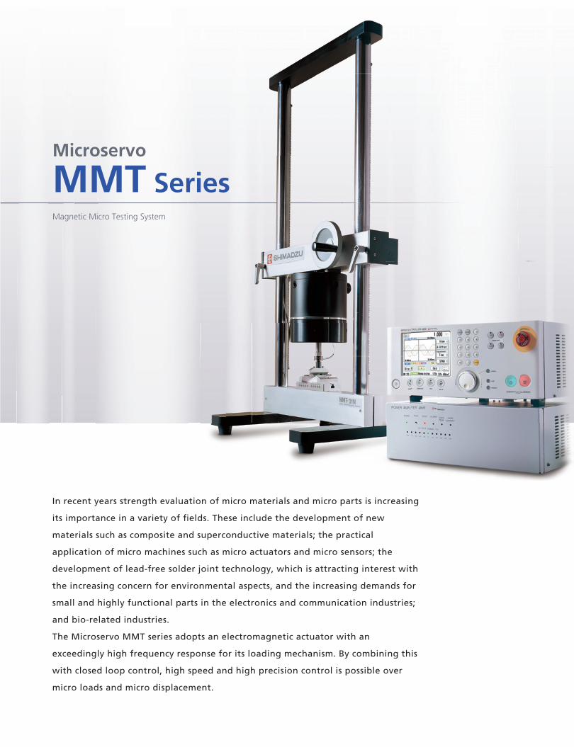
In recent years strength evaluation of micro materials and micro parts is increasing
its importance in a variety of fields. These include the development of new
materials such as composite and superconductive materials; the practical
application of micro machines such as micro actuators and micro sensors; the
development of lead-free solder joint technology, which is attracting interest with
the increasing concern for environmental aspects, and the increasing demands for
small and highly functional parts in the electronics and communication industries;
and bio-related industries.
The Microservo MMT series adopts an electromagnetic actuator with an
exceedingly high frequency response for its loading mechanism. By combining this
with closed loop control, high speed and high precision control is possible over
micro loads and micro displacement.
100
100 G10 G1 G0.1 G0.01 G100
10
1
101Frequency (Hz)
Am
plitu
de (m
m)
0.10.1
0.01 cm/sec 0.1 cm/sec 1 cm/sec
cm/sec
10
cm/sec
100
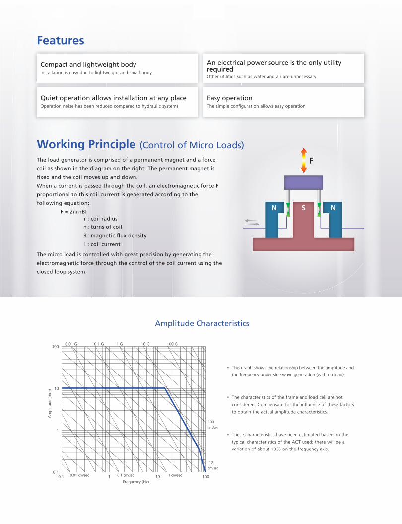
Amplitude Characteristics
• This graph shows the relationship between the amplitude and
the frequency under sine wave generation (with no load).
• The characteristics of the frame and load cell are not
considered. Compensate for the influence of these factors
to obtain the actual amplitude characteristics.
• These characteristics have been estimated based on the
typical characteristics of the ACT used; there will be a
variation of about 10% on the frequency axis.
N S N
F
F = 2πrnBI
Working Principle (Control of Micro Loads)
: coil radius
: turns of coil
: coil current
r
n
B
I
Features
Compact and lightweight body An electrical power source is the only utility required required
Quiet operation allows installation at any place Easy operation
Installation is easy due to lightweight and small body
Operation noise has been reduced compared to hydraulic systems
Other utilities such as water and air are unnecessary
The load generator is comprised of a permanent magnet and a force
coil as shown in the diagram on the right. The permanent magnet is
fixed and the coil moves up and down.
When a current is passed through the coil, an electromagnetic force F
proportional to this coil current is generated according to the
following equation:
The micro load is controlled with great precision by generating the
electromagnetic force through the control of the coil current using the
closed loop system.
4
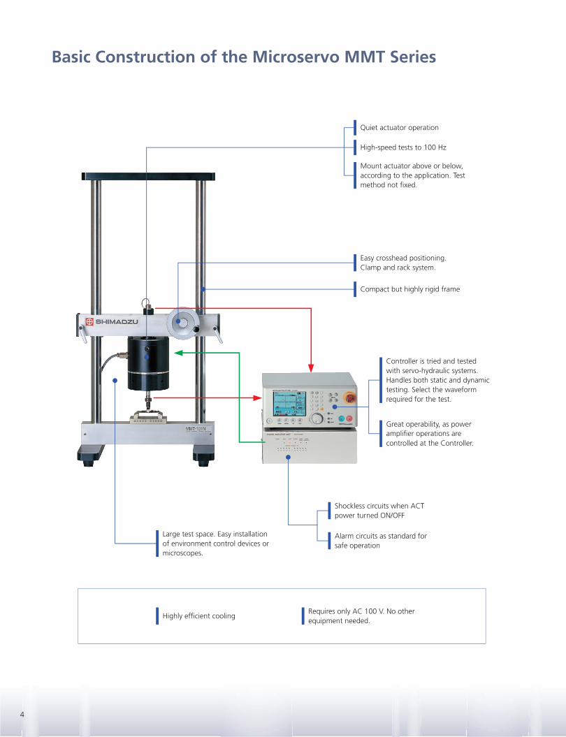
Basic Construction of the Microservo MMT Series
Shockless circuits when ACT power turned ON/OFF
Easy crosshead positioning.Clamp and rack system.
Alarm circuits as standard for safe operation
Highly efficient coolingRequires only AC 100 V. No other equipment needed.
Controller is tried and tested with servo-hydraulic systems. Handles both static and dynamic testing. Select the waveform required for the test.
Great operability, as power amplifier operations arecontrolled at the Controller.
Mount actuator above or below, according to the application. Test method not fixed.
Large test space. Easy installation of environment control devices or microscopes.
Quiet actuator operation
High-speed tests to 100 Hz
Compact but highly rigid frame

5Microservo MMT Series
Magnetic Micro Testing System
Selection of the right materials for
optimized design, Examination of the best
structure, Cost reduction, Improving the
reliability of products, Development of
environmentally friendly products, . . . etc.
Electrical Parts
Lead-Free Solder
Medical andDental Materials
Medical Products Food Products
MEMSThin Objects
Ceramics
Various Standards
Electronic Parts
Mobile Phones
SuperconductiveMaterials
Microfibers
Endurance testing and
vibration testing of connectors,
switches, and sensors
Board bending tests
Key pressing tests
Liquid crystal compression
tests
Endurance testing and
vibration testing of connectors,
switches, and sensors
Bonding wire tensile tests
IC chip shearing tests
Lead pull tests
Vibration tests
Robustness of terminations and integral
mounting devices (IEC 60068-2-21)
Endurance testing of IC cards
(JIS X6305)
Artificial blood vessels
Biomaterials
Endurance testing of teeth and bones
Compression testing of
capsules and pills
Tensile testing of paper, foil
and film
Texture tests
High temperature bending
tests
Tensile testing of carbon fibers, glass
fibers and aramid fibers
Tensile testing
Materials evaluation at very
low temperatures
Tensile tests
Shear fatigue tests
Endurance testing of micro
machines, micro elements, and
shape-memory alloys
Evaluation of Physical Properties,Endurance and Fatigue Strength
Applications
for

6
Tensile Test JigTest force: 100 NSpecimen shape: Round bar (ø4)orflat plate (1 mm thickness × 5 mmwidth maximum)
Test force: 100 NSpecimen shape: Round bar (ø0.5to 3 mm)orflat plate (1 mm thickness × 4 mmwidth maximum)
Test force: 100 NPunch tip radius: ø3Punch material: RubberSpecimen:Mobile phones, keyboards
Test force: 100 NLower platen: ø110 mmUpper platen: ø30 mm* Various compression testing jigs,including tooth type, spherical typeand those for key pressing tests, are available.
Test force: 100 NPunch tip radius × width: R2 × 60mmSupport roller radius × width:R2 × 60 mmSupport spacing: 20 to 100 mm
Test force: 100 NPunch tip radius × width: R2 × 60 mmPunch span: 20 to 60 mmSupport roller radius × width:R2 × 60 mmSupport spacing: 20 to 100 mm
Temperature range: Roomtemperature + 10 to 300°C Temperature range: Room
temperature + 10 to 50°C
Compression Test JigDrill Chuck Grip Key Pressing Test Jig
3-Point Bending Test Jig 4-Point Bending Test Jig Thermostatic Chamber Constant Temperature WaterImmersion Test Equipment
Microscope Excitation Table Card Insertion Test Jig X-Y StageDistance: ± 12.5 mm
Applicable Test Devices
Major Specifications
1000 × 500 × 1200 mm (approx.)
approx. 150 kg
MMT-500NV-10
Max. ± 500 N
348-20803-00
MMT-101NV-10
348-20801-00
MMT-101NV-2
Max. ± 100 N
MMT-250NV-10
348-20802-00
Max. ± 250 N
MMT-11NV-2
Max. ± 10 N
Test force, piston stroke (can be expanded by adding options)
Main Unit Model
Part No.
Test force
Piston stroke
Frequency
Controlled items
Load cell (standard accessory*1)
Jigs and test devices
Indication accuracy
Installation space (W × D × H)
Total weight
Power supply
within ± 0.5% indicated value or within ± 0.02% dynamic max. test force, whichever is larger*2
Not included in standard configuration (standard specification). (Select options or consult Shimadzu.)
within ± 1% indicated value or within ± 0.1% max. stroke, whichever is larger: :
348-20801-01 348-20800-01
Max. ± 2 mmMax. ± 10 mm
7
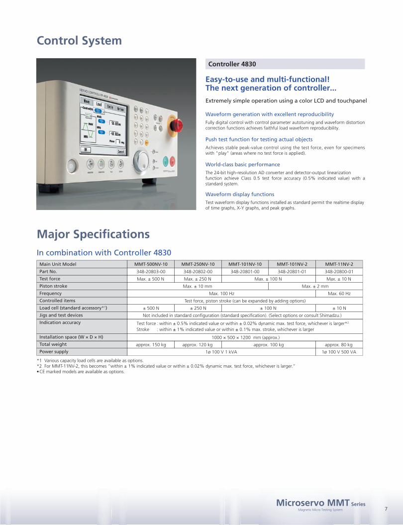
Controller 4830
Easy-to-use and multi-functional!The next generation of controller...
Extremely simple operation using a color LCD and touchpanel
Waveform generation with excellent reproducibility
Push test function for testing actual objects
World-class basic performance
Waveform display functions
Fully digital control with control parameter autotuning and waveform distortioncorrection functions achieves faithful load waveform reproducibility.
Achieves stable peak-value control using the test force, even for specimenswith "play" (areas where no test force is applied).
The 24-bit high-resolution AD converter and detector-output linearizationfunction achieve Class 0.5 test force accuracy (0.5% indicated value) with a standard system.
Test waveform display functions installed as standard permit the realtime displayof time graphs, X-Y graphs, and peak graphs.
In combination with Controller 4830
*1 Various capacity load cells are available as options.*2 For MMT-11NV-2, this becomes “within ± 1% indicated value or within ± 0.02% dynamic max. test force, whichever is larger.”•CE marked models are available as options.
Control System
approx. 120 kg approx. 100 kg approx. 80 kg
1ø 100 V 1 kVA
Max. 100 Hz
± 500 N ± 250 N ± 100 N ± 10 N
Max. 60 Hz
1ø 100 V 500 VA
Microservo MMT SeriesMagnetic Micro Testing System
Test force Stroke
Company names, product/service names and logos used in this publication are trademarks and trade names of Shimadzu Corporation or its affiliates, whether or not they are used with trademark symbol “TM” or “®”.Third-party trademarks and trade names may be used in this publication to refer to either the entities or their products/services. Shimadzu disclaims any proprietary interest in trademarks and trade names other than its own.
For Research Use Only. Not for use in diagnostic procedures. The contents of this publication are provided to you “as is” without warranty of any kind, and are subject to change without notice. Shimadzu does not assume any responsibility or liability for any damage, whether direct or indirect, relating to the use of this publication.
© Shimadzu Corporation, 2013www.shimadzu.com/an/
Microservo M
MT Series
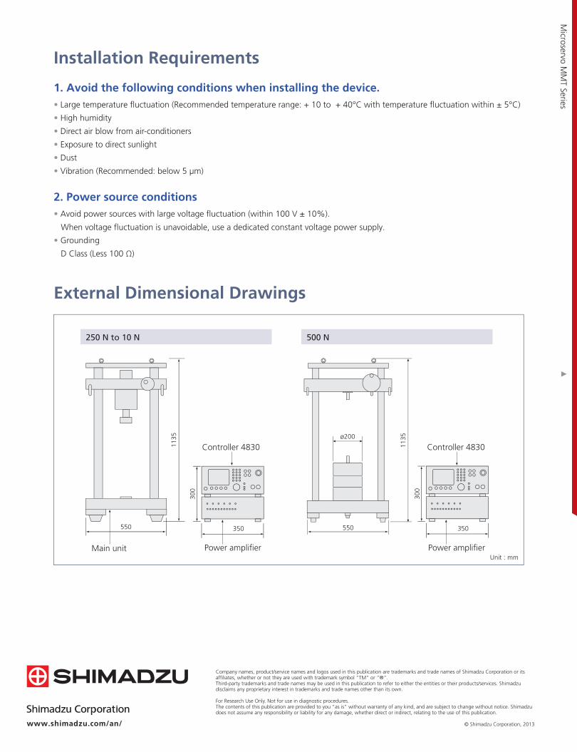
350550
1135
300
250 N to 10 N
Main unit Power amplifier Power amplifier
550
1135
350
300
500 N
ø200
Controller 4830
Unit : mm
Installation Requirements
External Dimensional Drawings
1. Avoid the following conditions when installing the device.
• High humidity
• Large temperature fluctuation (Recommended temperature range: + 10 to + 40°C with temperature fluctuation within ± 5°C)
• Direct air blow from air-conditioners
• Exposure to direct sunlight
• Dust
• Vibration (Recommended: below 5 μm)
2. Power source conditions
• Grounding
• Avoid power sources with large voltage fluctuation (within 100 V ± 10%).
D Class (Less 100 Ω)
When voltage fluctuation is unavoidable, use a dedicated constant voltage power supply.
Controller 4830