Embed Size (px)
Citation preview

IEEE Std C37.48™-2005(Revision of IEEE Std C37.48-1997)
C37.48TM
IEEE Guide for the Application,Operation, and Maintenance of High-Voltage Fuses, DistributionEnclosed Single-Pole Air Switches,Fuse Disconnecting Switches, andAccessories
3 Park Avenue, New York, NY10016-5997, USA
IEEE Power Engineering Society
Sponsored by theSwitchgear Committee
20 May 2005
Print: SH95318PDF: SS95318

The Institute of Electrical and Electronics Engineers, Inc.3 Park Avenue, New York, NY 10016-5997, USA
Copyright © 2005 by the Institute of Electrical and Electronics Engineers, Inc.All rights reserved. Published 20 May 2005. Printed in the United States of America.
IEEE is a registered trademark in the U.S. Patent & Trademark Office, owned by the Institute of Electrical and ElectronicsEngineers, Incorporated.
National Electrical Code and NEC are both registered trademarks in the U.S. Patent & Trademark Office, owned by theNational Fire Protection Association, Incorporated.
Print: ISBN 0-7381-4667-6 SH95318PDF: ISBN 0-7381-4668-4 SS95318
No part of this publication may be reproduced in any form, in an electronic retrieval system or otherwise, without the priorwritten permission of the publisher.
IEEE Std C37.48™-2005(Revision of
IEEE Std C37.48-1997)
IEEE Guide for the Application, Operation, and Maintenance of High-Voltage Fuses, Distribution Enclosed Single-Pole Air Switches, Fuse Disconnecting Switches, and Accessories
Sponsor
Switchgear Committeeof theIEEE Power Engineering Society
Approved 24 January 2005
IEEE-SA Standards Board
Abstract: Information on the application, operation and maintenance of high-voltage fuses (above1000 V and through 169 kV), distribution enclosed single-pole air switches, fuse disconnectingswitches, and accessories for use on ac distribution systems is provided. These include enclosed,open, and open-link types of distribution cutouts and fuses; distribution current-limiting fuses; dis-tribution enclosed single-pole air switches; power fuses, including current-limiting types; outdoorand indoor fuse disconnecting switches; fuse supports, mountings, and links, all of the type usedexclusively with the above; and removable switch blades for certain products among the above.Keywords: current-limiting fuses, expulsion type fuses, distribution class fuses, power class fuses,fuse enclosure packages, high-voltage fuses, fuse, fuse applications, fuse disconnecting switches

IEEE Standards documents are developed within the IEEE Societies and the Standards Coordinating Committees of theIEEE Standards Association (IEEE-SA) Standards Board. The IEEE develops its standards through a consensusdevelopment process, approved by the American National Standards Institute, which brings together volunteersrepresenting varied viewpoints and interests to achieve the final product. Volunteers are not necessarily members of theInstitute and serve without compensation. While the IEEE administers the process and establishes rules to promote fairnessin the consensus development process, the IEEE does not independently evaluate, test, or verify the accuracy of any of theinformation contained in its standards.
Use of an IEEE Standard is wholly voluntary. The IEEE disclaims liability for any personal injury, property or otherdamage, of any nature whatsoever, whether special, indirect, consequential, or compensatory, directly or indirectly resultingfrom the publication, use of, or reliance upon this, or any other IEEE Standard document.
The IEEE does not warrant or represent the accuracy or content of the material contained herein, and expressly disclaimsany express or implied warranty, including any implied warranty of merchantability or fitness for a specific purpose, or thatthe use of the material contained herein is free from patent infringement. IEEE Standards documents are supplied “AS IS.”
The existence of an IEEE Standard does not imply that there are no other ways to produce, test, measure, purchase, market,or provide other goods and services related to the scope of the IEEE Standard. Furthermore, the viewpoint expressed at thetime a standard is approved and issued is subject to change brought about through developments in the state of the art andcomments received from users of the standard. Every IEEE Standard is subjected to review at least every five years forrevision or reaffirmation. When a document is more than five years old and has not been reaffirmed, it is reasonable toconclude that its contents, although still of some value, do not wholly reflect the present state of the art. Users are cautionedto check to determine that they have the latest edition of any IEEE Standard.
In publishing and making this document available, the IEEE is not suggesting or rendering professional or other servicesfor, or on behalf of, any person or entity. Nor is the IEEE undertaking to perform any duty owed by any other person orentity to another. Any person utilizing this, and any other IEEE Standards document, should rely upon the advice of a com-petent professional in determining the exercise of reasonable care in any given circumstances.
Interpretations: Occasionally questions may arise regarding the meaning of portions of standards as they relate to specificapplications. When the need for interpretations is brought to the attention of IEEE, the Institute will initiate action to prepareappropriate responses. Since IEEE Standards represent a consensus of concerned interests, it is important to ensure that anyinterpretation has also received the concurrence of a balance of interests. For this reason, IEEE and the members of itssocieties and Standards Coordinating Committees are not able to provide an instant response to interpretation requests exceptin those cases where the matter has previously received formal consideration. At lectures, symposia, seminars, or educationalcourses, an individual presenting information on IEEE standards shall make it clear that his or her views should be consideredthe personal views of that individual rather than the formal position, explanation, or interpretation of the IEEE.
Comments for revision of IEEE Standards are welcome from any interested party, regardless of membership affiliation withIEEE. Suggestions for changes in documents should be in the form of a proposed change of text, together with appropriatesupporting comments. Comments on standards and requests for interpretations should be addressed to:
Secretary, IEEE-SA Standards Board
445 Hoes Lane
Piscataway, NJ 08854
USA
Authorization to photocopy portions of any individual standard for internal or personal use is granted by the Institute ofElectrical and Electronics Engineers, Inc., provided that the appropriate fee is paid to Copyright Clearance Center. Toarrange for payment of licensing fee, please contact Copyright Clearance Center, Customer Service, 222 Rosewood Drive,Danvers, MA 01923 USA; +1 978 750 8400. Permission to photocopy portions of any individual standard for educationalclassroom use can also be obtained through the Copyright Clearance Center.
NOTE−Attention is called to the possibility that implementation of this standard may require use of subjectmatter covered by patent rights. By publication of this standard, no position is taken with respect to the exist-ence or validity of any patent rights in connection therewith. The IEEE shall not be responsible for identifyingpatents for which a license may be required by an IEEE standard or for conducting inquiries into the legal valid-ity or scope of those patents that are brought to its attention.

Introduction
This guide is a revision of IEEE Std C37.48™-1997 to bring it up-to-date and in line with present dayrequirements for high-voltage fuses and switches. Significant changes include the clarification and expan-sion of application areas that have been reported as causing some confusion. Some additional informationregarding the effect of ambient temperature on the current rating of a fuse has been added, as well as infor-mation regarding parallel fuses.
This guide was prepared by the Revision of Fuse Standards working group of the IEEE Subcommittee onHigh-Voltage Fuses. Liaison was maintained with the International Electrotechnical Commission (IEC) dur-ing the development of the revisions in order to incorporate the latest activities at the time of publication. Itis one of a series of complementary standards covering various types of high-voltage fuses and switches,arranged so that certain standards apply to all devices while other standards provide additional specificationsfor a particular device. For any device, IEEE Std C37.40™-2003, IEEE Std C37.41™-2000, plus anyadditional standards covering that device, constitute a complete standard for the device. In addition, thisdocument provides application, operation, and maintenance guidance for all the devices, and is supple-mented by IEEE Std C37.48.1™-2002, which is an operation, classification, application, and coordinationguide for current-limiting fuses.
The following standards make up this series:
ANSI C37.42-1996, American National Standard Specifications for High Voltage Expulsion Type Distribu-tion Class Fuses, Cutouts, Fuse Disconnecting Switches and Fuse Links.
ANSI C37.45-1981 (R1992), American National Standard Specifications for Distribution Enclosed Single-Pole Air Switches.
ANSI C37.46-2000, American National Standard for High Voltage Expulsion and Current-limiting TypePower Class Fuses and Fuse Disconnecting Switches.
ANSI C37.47-2000, American National Standard for High-Voltage Current-limiting Type DistributionClass Fuses and Fuse Disconnecting Switches.
IEEE Std C37.40™-2003, IEEE Standard Service Conditions and Definitions for High-Voltage Fuses, Distri-bution Enclosed Single-Pole Air Switches, Fuse Disconnecting Switches, and Accessories.
IEEE Std C37.41™-2000, IEEE Standard Design Tests for High-Voltage Fuses, Distribution Enclosed Sin-gle-Pole Air Switches, Fuse Disconnecting Switches, and Accessories.
IEEE Std C37.48™ -2004, IEEE Guide for Application, Operation, and Maintenance of High-Voltage Fuses,Distribution Enclosed Single-Pole Air Switches, Fuse Disconnecting Switches, and Accessories.
IEEE Std C37.48.1™-2002, IEEE Guide for the Operation, Classification, Application, and Coordination ofCurrent-Limiting Fuses with Rated Voltages 1–38 kV.
This introduction in not part of IEEE Std C37.48-2005, IEEE Guide for the Application, Operation, and Mainte-nance of High-Voltage Fuses, Distribution Enclosed Single-Pole Air Switches, Fuse Disconnecting Switches, andAccessories.
Copyright © 2005 IEEE. All rights reserved. iii
Notice to users
Errata
Errata, if any, for this and all other standards can be accessed at the following URL: http://standards.ieee.org/reading/ieee/updates/errata/index.html. Users are encouraged to check this URL forerrata periodically.
Interpretations
Current interpretations can be accessed at the following URL: http://standards.ieee.org/reading/ieee/interp/index.html.
Patents
Attention is called to the possibility that implementation of this standard may require use of subject mattercovered by patent rights. By publication of this standard, no position is taken with respect to the existence orvalidity of any patent rights in connection therewith. The IEEE shall not be responsible for identifyingpatents or patent applications for which a license may be required to implement an IEEE standard or forconducting inquiries into the legal validity or scope of those patents that are brought to its attention.
iv Copyright © 2005 IEEE. All rights reserved.

Participants
At the time this standard was completed, the working group on revision of fuse standards had the followingmembership:
John G. Leach, ChairGlenn R. Borchardt, Secretary
At the time of approval, the High-Voltage Fuse Subcommittee had the following membership:
Tim E. Royster, ChairJohn G. Leach, Secretary
The following members of the individual balloting committee voted on this standard. Balloters may havevoted for approval, disapproval, or abstention.
John G. Angelis Richard H. Arndt L. Ronald Beard Terrance A. Bellei Fredrick J. BrownH. Edward FoelkerStephen P. Hassler
James R. Marek Frank J. Muench Donald M. ParkerR. Neville ParryRadhakrishna Ranjan Philip Rosen Tim E. Royster
John S. Schaffer David ServiesMark W. Stavnes Frank M. StepniakJohn G. St.Clair E. M. “Al” WorlandJanusz Zawadzki
John G. Angelis Richard H. Arndt L. Ronald Beard Terrance A. Bellei Glenn R. Borchardt Fredrick J. BrownRaymond L. Capra
H. Edward FoelkerStephen P. Hassler James R. Marek Frank J. Muench R. Neville ParryHerbert M. PflanzRadhakrishna Ranjan
John S. Schaffer E. William Schmunk David ServiesMark W. Stavnes Frank M. StepniakJohn G. St.Clair John G. WoodJanusz Zawadzki
Donald AkersChris AmbroseWallace BinderGlenn BorchardtHarvey BowlesRobert BrownTed BurseRaymond CapraTommy CooperR. DaubertMatthew DavisGuru Dutt DhingraJerry DiSciulloAlexander DixonRandall DotsonAmir El-SheikhGary EngmannRabiz FodaMarcel FortinFredric Friend
Mietek GlinkowskiWilliam GoldbachRandall GrovesKen HanusJohn E. HarderEdward Horgan Jr.David JacksonJoseph L. KoepfingerDavid KrauseStephen R. LambertJohn LeachJason LinGregory LuriFrank MayleGary MichelGeorges MontilletCharles MorseFrank MuenchT.W. OlsenNeville Parry
Robert PuckettRadhakrishnan RanjanCarl ReigartMichael RobertsTimothy RoysterE. William SchmunkJames SmithJohn G. St. ClairAllan St. PeterFrank StepniakJohn TeixeiraStanton TelanderJane Ann VernerElbert WorlandCharles WagnerTom WandeloskiJames WilsonJanusz Zawadzki
Copyright © 2005 IEEE. All rights reserved
. v
When the IEEE-SA Standards Board approved this standard on 24 January 2005, it had the followingmembership:
Don Wright, ChairSteve M. Mills, Vice ChairJudith Gorman, Secretary
*Member Emeritus
Also included are the following nonvoting IEEE-SA Standards Board liaisons:
Satish K. Aggarwal, NRC RepresentativeRichard DeBlasio, DOE Representative
Alan Cookson, NIST Representative
Michael FisherIEEE Standards Project Editor
Chuck AdamsStephen BergerMark D. BowmanJoseph A. BruderBob DavisRoberto de Marca BoissonJulian Forster*Arnold M. GreenspanMark S. Halpin
Raymond HapemanRichard J. HollemanRichard H. HulettLowell G. JohnsonJoseph L. Koepfinger*Hermann KochThomas J. McGean
Daleep C. MohlaPaul NikolichT. W. OlsenRonald C. PetersenGary S. RobinsonFrank StoneMalcolm V. ThadenDoug ToppingJoe D. Watson
vi
Copyr ight © 2005 IEEE. All rights reserved.
Contents
1. Overview.............................................................................................................................................. 1
1.1 Scope............................................................................................................................................ 11.2 Background.................................................................................................................................. 21.3 Description of fuse-enclosure packages (FEPs) using expulsion-type indoor
power class fuses ......................................................................................................................... 21.4 Description of FEPs using current-limiting type indoor distribution and power class fuses ...... 2
2. References............................................................................................................................................ 3
3. Abbreviations....................................................................................................................................... 4
4. General application guidelines for all fuse types................................................................................. 4
4.1 Introduction.................................................................................................................................. 44.2 Service conditions........................................................................................................................ 54.3 Selection of class and type of fuse............................................................................................... 54.4 Clearances and spacing ................................................................................................................ 74.5 Fuse position ................................................................................................................................ 74.6 Noise level ................................................................................................................................... 74.7 Selection of fuse voltage rating ................................................................................................... 74.8 Selection of continuous current rating (all applications except capacitor fuses and
fuses used in enclosures—see 5.2, 5.3, and 5.4).......................................................................... 94.9 Selection of interrupting rating .................................................................................................. 124.10 Fuse-to-fuse coordination procedure ......................................................................................... 134.11 Coordination for motor starter fuses (motor protection) ........................................................... 144.12 Effects of ambient temperature on a fuse .................................................................................. 14
5. Additional application guidelines for specific devices ...................................................................... 16
5.1 Current-limiting fuses ................................................................................................................ 165.2 Current-limiting fuses used in fuse enclosure packages ............................................................ 245.3 Expulsion fuses in enclosures .................................................................................................... 265.4 External fuses for shunt capacitors ............................................................................................ 28
6. Operation guidelines for various fuse types ...................................................................................... 41
6.1 Use of nonexpendable cap on expendable-cap cutouts ............................................................. 416.2 Operating speed ......................................................................................................................... 416.3 Locking or latching of fuses, blades, or links in closed position ............................................... 416.4 Fuseholder position.................................................................................................................... 416.5 Voltage withstand of blown fuses.............................................................................................. 416.6 Replacement and handling of fuses ........................................................................................... 426.7 Replacement of exhaust control device ..................................................................................... 436.8 Operation of energized fuses ..................................................................................................... 436.9 Storing spare fuse units and replaceable parts ........................................................................... 43
7. Additional operation guidelines for specific devices......................................................................... 43
7.1 Capacitor fuses........................................................................................................................... 437.2 Liquid-submerged expulsion fuses in enclosures ...................................................................... 44
Copyright © 2005 IEEE. All rights reserved. vii

8. Maintenance for all fuse types ........................................................................................................... 44
8.1 Safety precautions...................................................................................................................... 448.2 Frequency of maintenance ......................................................................................................... 458.3 Inspection of fuse or switching device. ..................................................................................... 458.4 Inspection of fuse links in distribution cutouts .......................................................................... 45
9. Additional maintenance guidelines for specific devices.................................................................... 45
9.1 Capacitor fuses........................................................................................................................... 459.2 Liquid-submerged expulsion fuses in enclosures ...................................................................... 46
Annex A (informative) Bibliography ............................................................................................................ 47
viii Copyright © 2005 IEEE. All rights reserved.
IEEE Guide for the Application, Operation, and Maintenance of High-Voltage Fuses, Distribution Enclosed Single-Pole Air Switches, Fuse Disconnecting Switches, and Accessories
1. Overview
1.1 Scope
This guide presents information on the application, operation, and maintenance of high-voltage fuses (above1000 V), distribution enclosed single-pole air switches, fuse disconnecting switches, and accessories for useon ac distribution systems. Devices with rated maximum voltages to 169 kV are covered. These guidelinesapply to the following specific types of equipment:
a) Distribution and power class expulsion-type fuses.
b) Distribution and power class current-limiting type fuses.
c) Distribution and power class fuse disconnecting switches.
d) Items a) through c) used in fuse-enclosure packages (see types listed in 1.3 and 1.4).
e) Fuse supports, and fuse mountings, of the type intended for use with distribution and power classfuses, and fuse disconnecting switches.
f) Removable switch blades of the type used exclusively with distribution class oil cutouts, power classfuses, and distribution class fuse disconnecting switches.
g) Fuse links of the type used exclusively with distribution class oil cutouts, power class fuses, and dis-tribution class fuse disconnecting switches.
h) Distribution class oil cutouts.
i) Distribution class enclosed single-pole air switches.
j) Distribution and power classes of expulsion, current-limiting and combination external capacitorfuses used with a capacitor unit, groups of units, or capacitor banks.
Copyright © 2005 IEEE. All rights reserved. 1
IEEEStd C37.48-2005 IEEE GUIDE FOR THE APPLICATION, OPERATION, AND MAINTENANCE OF HIGH-VOLTAGE FUSES
1.2 Background
The distribution class and power class expulsion-type fuses listed in 1.1 are similar to those now covered inIEC 60282-2. The distribution class expulsion-type fuses are similar to the class “A” fuses covered in theIEC document and the power class fuses are similar to their class “B” fuses. At present, IEEE and ANSIstandards do not cover the class “C” fuses listed in the IEC standard. Some of the current-limiting type fuseslisted in 1.1 are similar to those now covered in IEC 60282-1. However, significant differences exist in thetesting requirements of IEC and IEEE/ANSI. IEEE fuse standards reflect, primarily, applications commonin North America, and in countries that use electrical systems designed using similar principles. IEC stan-dards tend to rely heavily on practices common in Europe. Since IEC testing differences include testing atdifferent voltages for the same fuse rated voltage, and different or no testing for fuses intended for use in asurrounding temperature above 40 °C, the user is advised to exercise extreme caution if devices specifiedand tested per IEC standards are compared to those specified and tested per IEEE/ANSI standards. The dif-ferences in test requirements may result in devices tested to IEC not being suitable for applications wheredevices tested to IEEE and ANSI standards are required, or vice versa.
In the headings and the text of this document there will be some areas where information is included inbrackets [ ]. The information in the brackets is a term used in IEC standards that may be similar to the termused in this document, a term that is common in some parts of the world, or a term that has been used previ-ously in IEEE or ANSI standards. Caution is again advised when making comparisons.
1.3 Description of fuse-enclosure packages (FEPs) using expulsion-type indoor power class fuses
— Type 1E: A fuse mounted in an enclosure with relatively free air circulation within the enclosure (forexample, an expulsion fuse mounted in an enclosure or in a vault)
— Type 2E: A fuse mounted in a container with restricted air flow surrounding the fuse, but relativelyfree air circulation within the enclosure on the outside of the container (for example, an expulsionfuse in an enclosure with insulating barriers that form a container that restricts the airflow)
— Type 3E: A fuse mounted in an enclosure, directly immersed in liquid, with relatively free liquid cir-culating around the fuse (for example, an expulsion fuse in a switchgear enclosure)
1.4 Description of FEPs using current-limiting type indoor distribution and power class fuses
— Type 1C: A fuse mounted in an enclosure with relatively free air circulation within the enclosure (forexample, a fuse mounted in a live front pad mounted transformer or in a vault)
— Type 2C: A fuse mounted in a container with restricted air flow surrounding the fuse, but with rela-tively free air circulation within the enclosure on the outside surfaces of the container (for example,a fuse inside a canister in a vault)
— Type 3C: A fuse mounted in a container with restricted air flow surrounding the fuse, but relativelyfree liquid circulating within the enclosure on the outside surfaces of the container (for example, afuse inside a canister immersed in transformer oil)
— Type 4C: A combination of types 2C and 3C, where the container is partially in air and partially inliquid (for example, a fuse inside a transformer bushing)
— Type 5C: A fuse mounted in an enclosure, directly immersed in liquid, with relatively free liquid cir-culation around the fuse (for example, an oil immersed fuse in a transformer or switchgearenclosure)
2 Copyright © 2005 IEEE. All rights reserved.

IEEEDISTRIBUTION ENCLOSED SINGLE-POLE AIR SWITCHES, FUSE DISCONNECTING SWITCES & ACCESSORIES Std C37.48-2005
2. References
It is intended that this standard be used in conjunction with the following referenced standards. When thestandard referenced below is superseded by an approved revision, the revised document may or may notapply. At the time of publication of this document, the editions listed below were valid. Since all standardsare subject to revision at varying times, a revised document may or may not apply. In the interim periodprior to revision of this standard, all parties making agreements based on these documents are encouraged toinvestigate the possibility of using the most recent editions of the relevant standards.
ANSI C37.46-2000, American National Standard for High Voltage Expulsion and Current-Limiting TypeDistribution Class Fuses and Fuse Disconnecting Switches. 1
ANSI C37.47-2000, American National Standard for High Voltage Current-Limiting Type DistributionClass Fuses and Fuse Disconnecting Switches.
IEC 60282-1 (2002-01-29), High-voltage fuses—Part 1:Current-limiting fuses.2
IEC 60282-2 (1997-12-17), High Voltage Fuses—Part 2: Expulsion fuses.
IEEE Std 18™-2002, IEEE Standard for Shunt Power Capacitors.3, 4
IEEE Std C37.40™ -2003, IEEE Standard Service Conditions and Definitions for High-Voltage Fuses, Dis-tribution Enclosed Single-Pole Air Switches, Fuse Disconnecting Switches, and Accessories.
IEEE Std C37.41™-2000, IEEE Standard Design Tests for High-Voltage Fuses, Distribution Enclosed Sin-gle-Pole Air Switches, Fuse Disconnecting Switches, and Accessories.
IEEE Std C37.48.1™-2002, IEEE Guide for the Operation, Classification, Application, and Coordination ofCurrent-limiting Fuses with Rated Voltages 1–38 kV.
IEEE Std C37.99™ -2000, IEEE Guide for the Protection of Shunt Capacitor Banks.
IEEE Std C62.92.2™, IEEE Guide for the Application of Neutral Grounding in Electrical Utility System PartII—Introduction.
IEEE Std C62.92.4™, IEEE Guide for the Application of Neutral Grounding in Electrical Utility SystemsPart IV –Distribution.
NEMA CP 1-2000, Shunt Capacitors.5
NFPA 70-2002: National Electrical Code® (NEC®).6
1ANSI publications are available from the Sales Department, American National Standards Institute, 25 West 43rd Street, 4th Floor,New York, NY 10036, USA (http://www.ansi.org/).2IEC publications are available from the Sales Department of the International Electrotechnical Commission, Case Postale 131, 3, ruede Varembé, CH-1211, Genève 20, Switzerland/Suisse (http://www.iec.ch/). IEC publications are also available in the United Statesfrom the Sales Department, American National Standards Institute, 25 West 43rd Street, 4th Floor, New York, NY 10036, USA (http://www.ansi.org/).3IEEE publications are available from the Institute of Electrical and Electronics Engineers, Inc., 445 Hoes Lane, Piscataway, NJ 08854,USA (http://standards.ieee.org/).4The IEEE standards or products referred to in this clause are trademarks of the Institute of Electrical and Electronics Engineers, Inc.5NEMA publications are available from Global Engineering Documents, 15 Inverness Way East, Englewood, CO 80112, USA (http://global.ihs.com/).6The NEC is published by the National Fire Protection Association, Batterymarch Park, Quincy, MA 02269, USA (http://www.nfpa.org). Copies are also available from the Institute of Electrical and Electronics Engineers, Inc., 445 Hoes Lane, Piscataway, NJ 08854, USA (http://standards.ieee.org/).
Copyright © 2005 IEEE. All rights reserved. 3
IEEEStd C37.48-2005 IEEE GUIDE FOR THE APPLICATION, OPERATION, AND MAINTENANCE OF HIGH-VOLTAGE FUSES
NFPA 70E, 2004 Edition: Electrical Safety in the Workplace.
NOTE—Fuse standards listed as “ANSI C37.xx”, were formerly developed by NEMA. The responsibility for maintain-ing them has passed to the IEEE and, at their next revision, they will carry the designation “IEEE C37.xx”.7
3. Abbreviations
FEP fuse enclosure package
F/C fuse container
RMAT rated maximum application temperature
TCC time-current characteristic
4. General application guidelines for all fuse types
4.1 Introduction
The application, operation, and maintenance of equipment covered by this guide is the responsibility of theuser, who is expected to take into account system-specific requirements. As an aid in obtaining satisfactoryperformance of equipment, this guide provides information on some of the more important features of theabove functions for normal conditions of service; unusual conditions may require special measures.
Although fuses are single-phase devices, they can be applied with single- or three-phase equipment or lines,or a combination of these. However, characteristics of the power system should be considered when select-ing all fuses.
A fuse, when applied in an electric circuit within the limits of its ratings, protects the circuit. Its primaryfunction is to isolate faulted equipment from the system. When applied with other equipment in a coordi-nated overcurrent protection scheme, it may also limit service interruptions to only a predetermined sectionof a power system. In many applications, it is possible that the equipment connected to the system can beprotected from excessive damage. In this latter application, the primary function is to remove the faultedequipment from the system, and the secondary function is to minimize, or in some cases prevent, damage tothe connected equipment as much as possible, considering the varying fault or overload circumstances thatcan occur.
Fuse performance depends upon the integrity, including quality assurance and quality control processes,with which the fuse was manufactured, the correctness of its application, and the attention it receives after itis installed. If not properly applied and maintained, it might not perform properly when required, whichmight result in considerable damage to costly equipment or extensive interruptions in service.
It cannot be stressed too strongly that prescribed safety rules and manufacturers’ recommendations andinstructions should be adhered to at all times when operating or maintaining these devices near energizedequipment or conductors. This is especially true for devices where air-insulated blades, insulating barriersor liners, or fuses are removed or replaced while mating contacts are energized. (In some cases, NFPA 70E,2004 Edition may be applicable.)
7Notes in text, tables, and figures are given for information only, and do not contain requirements needed to implement the standard.
4 Copyright © 2005 IEEE. All rights reserved.
IEEEDISTRIBUTION ENCLOSED SINGLE-POLE AIR SWITCHES, FUSE DISCONNECTING SWITCES & ACCESSORIES Std C37.48-2005
4.2 Service conditions
4.2.1 Usual
Usual service conditions conforming to this guide are defined in IEEE Std C37.40-2003. These conditionsspecify limits in altitude and ambient temperature.
4.2.2 Unusual
Unusual service conditions are defined in IEEE Std C37.40-2003, which gives examples of such conditions.Equipment covered by IEEE Std C37.40 that depends on air at atmospheric pressure for its insulating andcooling medium will have a higher temperature rise and a lower dielectric withstand when operated at alti-tudes higher than 1000 m. Historically, equipment covered by IEEE Std C37.40 has used correction factorsfor dielectric strength and rated continuous current when applied at altitudes above 1000 m. In addition,equipment designed for standard temperature use could be used at its normal rated continuous current with-out exceeding ultimate standard temperature limits if the ambient temperature did not exceed the maximumambient temperature assigned to the device in accordance with IEEE Std C37.40-2003, multiplied by anappropriate factor. Altitude correction factors are being studied by the Switchgear Committee, and will beadded to IEEE Std C37.40-2003 directly or by reference when they are approved. In the meantime, usersshould consult the manufacturer for appropriate derating when the equipment is applied above 1000 m.
If, during service, the fuse will be subjected to mechanical vibratory stress that may damage the fuse ele-ment, the manufacturer should be consulted to verify that it can withstand these conditions.
4.3 Selection of class and type of fuse
No generalizations can be made about selecting the class and type of fuse that should be used at a particularlocation. In selection of the class of fuse, factors such as power being supplied, dielectric properties of theequipment being protected, X/R ratios, fault currents available, and transient recovery voltage (TRV) sever-ity require consideration. The major classes of fuses are power class and distribution class.
4.3.1 Fuse class
4.3.1.1 Power class fuses
Power class fuses are as follows:
a) Generally used in three-phase applications.
b) Generally used in substations, cabinets, or vaults where a large amount of electrical power is beingsupplied to a distribution system or in a facility that requires large quantities of energy.
c) Generally used in that part of a system where high dielectric properties are required for allequipment.
d) Normally placed in a position on the system where fault currents are high, X/R ratios are high, andTRV characteristics are more severe than those found in the applications where distribution fusesare used.
e) Used in single-phase applications where severe faults, high X/R, or severe TRV is anticipated in anarea where distribution fuses would normally be used.
4.3.1.2 Distribution class fuses
Distribution class fuses are as follows:
a) Generally used in single-phase applications.
Copyright © 2005 IEEE. All rights reserved. 5
IEEEStd C37.48-2005 IEEE GUIDE FOR THE APPLICATION, OPERATION, AND MAINTENANCE OF HIGH-VOLTAGE FUSES
b) Generally used in the distribution line on single-phase taps for sectionalizing purposes or for pro-tecting single-phase transformers supplying residential or small business energy requirements.
c) Generally used in that part of a system where the requirements of the system can be accommodatedby the distribution fuse’s rated interrupting capabilities, and dielectric properties.
d) Suitable for use in three-phase applications where the high capabilities of the power fuse are notrequired and other application requirements are met.
4.3.2 Fuse types
4.3.2.1 Expulsion-type fuses
An expulsion fuse is a vented device in which the expulsion effect of the gases produced by the interactionof the arc with other parts of the fuse results in the current interruption in the circuit. A consideration in theirapplication is the criteria that the gases expelled are properly directed, and that the noise and pressurecreated is acceptable. Some power class expulsion fuses can be provided with an exhaust-control device tovirtually eliminate the effect of these gases. Manufacturers’ recommendations for the use of expulsion-typefuses should be followed. In most cases, expulsion fuses do not appreciably limit the circuit’s prospectivefault current.
4.3.2.2 Non-expulsion-type fuses
Non-expulsion-type fuses may be current-limiting or non-current-limiting. When a current-limiting fuse isexposed to a current high enough to produce melting before the first peak of current, it abruptly introducessufficient resistance into the circuit to prevent that peak being reached. The lowest current at which a partic-ular fuse exhibits this current-limiting action is called its threshold current. Typically, this current may befrom about 25 to 50 times the fuse’s current rating, depending on fuse design and circuit X/R. This guidewill refer to such currents as “high” currents. Current-limiting fuses can also interrupt lower currents, onesthat do not produce a current-limiting action. However, differences in the ability of certain types of design tointerrupt these “low” currents leads to three different classes of current-limiting fuses—backup, general-pur-pose, and full-range. IEEE Std C37.48.1 discusses the design and application of current-limiting fuses inmore detail. The major uses for non-expulsion-type fuses are in applications where the clearances togrounded parts are limited or the current-limiting properties of current-limiting fuses are required.
4.3.2.2.1 Backup current-limiting fuse
This is a current-limiting fuse that provides only fault current interrupting duty from its rated maximuminterrupting current down to its rated minimum interrupting current (see 5.1.3.1). Some auxiliary device isused to interrupt any lower faults or overcurrents. The low current interrupting ability of different types ofbackup fuses varies significantly. The minimum interrupting current of a particular type or rating may pro-duce a melting time as short as a few cycles to as long as 1000 s or more.
4.3.2.2.2 General-purpose current-limiting fuse
This is a current-limiting fuse that can satisfactorily interrupt high and low fault currents and overcurrents. Itis required that a fuse must demonstrate an interrupting capability with currents as low as will cause themelting time of the fuse to be at least 1 h (see 5.1.3.2).
4.3.2.2.3 Full-range current-limiting fuse
This is a current-limiting fuse that can satisfactorily interrupt high and low fault currents, as well as anyovercurrent that causes the fuse to melt, with the fuse applied at its rated maximum application temperaturespecified (see 4.12.1 and 5.1.3.3).
6 Copyright © 2005 IEEE. All rights reserved.

IEEEDISTRIBUTION ENCLOSED SINGLE-POLE AIR SWITCHES, FUSE DISCONNECTING SWITCES & ACCESSORIES Std C37.48-2005
4.3.2.2.4 Non-current-limiting fuses
There are other types of non-expulsion-type fuses such as liquid fuses, vacuum fuses, or SF6 fuses. How-ever, their application is very special. In all cases the manufacturer’s recommendations should be followed.These types of non-expulsion fuses do not appreciably limit the circuit’s prospective fault current.
4.4 Clearances and spacing
Minimum electrical spacings and clearances for power fuse and disconnecting switch installations shall bein accordance with tables 7, 8, and 9 of ANSI C37.46-2000. The application should recognize the conditionsprevalent during design testing (per IEEE Std C37.41-2000) and generally conform to the test clearancesand conditions as a minimum, unless the manufacturer recommends the minimum clearances to be observed.
Expulsion fuses should be applied with adequate clearance in the direction or directions in which theyare vented, and facilities should be provided to ensure that operators are not exposed to fuse dischargeseither during replacement or when working in the area. When this is not possible, the circuit should bede-energized.
4.5 Fuse position
The positioning of the fuses should be such that their operation is facilitated. When devices are used by autility, the operating practices of that utility should be adhered to.
4.6 Noise level
Expulsion fuses may produce intense short-term noise levels during fault interruption. The height, location,and exhaust control of expulsion fuses should be such as to minimize the noise level at any location nor-mally occupied by personnel. Some power-class expulsion fuses can be provided with an exhaust-controldevice to virtually eliminate the noise produced during an interruption.
4.7 Selection of fuse voltage rating
(See 5.4.2.2 and 5.4.3.2 for specific guidelines for voltage rating selection for capacitor fuses.)
The selection of the proper voltage rating for fuses is based on consideration of the following systemparameters:
a) Maximum system line-to-line or line-to-ground power-frequency recovery voltage.
b) System neutral grounding.
c) Single- or three-phase circuits
The rated voltage of expulsion fuses may exceed the system voltage by any desired amount. Care should betaken in applying current-limiting fuses with higher voltage ratings than the system voltage. Current-limit-ing fuses can produce peak arc voltages higher than the fuse voltage rating. These overvoltages should notexceed system and equipment insulation levels. The sparkover voltage of source side connected surge arrest-ers should be considered. The fuse manufacturer’s recommendations should be followed in this regard.
4.7.1 Power class fuses
The fuse should have a maximum voltage rating equal to or exceeding the maximum system line-to-linevoltage.
Copyright © 2005 IEEE. All rights reserved. 7
IEEEStd C37.48-2005 IEEE GUIDE FOR THE APPLICATION, OPERATION, AND MAINTENANCE OF HIGH-VOLTAGE FUSES
Most power fuses are used on three-phase applications. When used on a single-phase circuit of an effec-tively grounded system (see IEEE Std C62.92 for a description of system grounding), the fuse should have amaximum voltage rating of at least 1.15 times maximum line-to-ground voltage of the system. However, ifthe fuse has been tested for rated interrupting current at rated maximum voltage, or if the fault current wherethe fuse is to be applied does not exceed 87% of the fuse rated interrupting current, then the fuse need onlyhave a maximum voltage rating equal to or greater than the maximum line-to-ground voltage of the system,when applied on a single-phase circuit of an effectively grounded system.
4.7.2 Distribution class fuses
4.7.2.1 Fuses for ungrounded-neutral systems or systems having higher resistance grounding than effectively grounded neutral (multigrounded) systems
A single-voltage rated distribution fuse should have a maximum voltage rating equal to or exceeding themaximum system line-to-line voltage. A slant-voltage-rated (multiple-voltage-rated) cutout (e.g., 15/27 kV)should have a maximum voltage rating to the left of the slant equal to or exceeding the maximum systemline-to-line voltage.
4.7.2.2 Fuses for effectively grounded-neutral (multigrounded) systems
4.7.2.2.1 Single-voltage-rated distribution fuses
a) In single-phase, line-to-neutral circuits, the fuse should have a maximum voltage rating equal to orexceeding the maximum system line-to-ground voltage, and a basic insulation level (BIL) coordi-nated with the line-to-ground insulation of other connected apparatus.
b) In three-phase circuits where multiphase faults not involving ground can occur, the fuse should havea maximum voltage rating equal to or exceeding the maximum system line-to-line voltage.
c) In three-phase circuits where multiphase faults not involving ground cannot occur or are unlikely(for example, where phase isolation is employed as in underground or cubicle construction), and thefuse is not required to protect transformers against secondary faults of the types that would imposegreater than line-to-ground recovery voltage, the fuse may have a maximum voltage rating equal toor exceeding the maximum system line-to-ground voltage. It should have a BIL coordinated with theline-to-ground insulation of other connected apparatus. Another device may be required to cleartransformer secondary faults, should they occur.
4.7.2.2.2 Slant-voltage-rated (multiple-voltage-rated) distribution cutouts
a) In single-phase, line-to-neutral circuits, the cutout should have a maximum voltage rating to the leftof the slant equal to or exceeding the maximum system line-to-ground voltage.
b) In three-phase circuits, the cutout should have a maximum voltage rating to the right of the slantequal to or exceeding the maximum system line-to-line voltage. Some of the criteria for using slant-voltage-rated cutouts in three-phase circuits as herein set forth are:
1) Three-phase faults not involving ground, which impose 87% of line-to-line voltage across thefirst cutout to clear, seldom occur. Operation of another device may be required to clear suchfaults, but experience indicates such cases are rare.
2) Phase-to-phase faults not involving ground generally cause two cutouts to operate in series toclear the fault. Even with differences in fuse-link melting time, both cutouts work together toclear high-current faults. On medium-current faults, the possibility exists of load current con-tinuing to flow through one of the cutouts, after fault clearing by series operation of the twocutouts. Operation of another device may be required if the cutout does not clear the continuingload current, but experience indicates that such cases are rare.
8 Copyright © 2005 IEEE. All rights reserved.

IEEEDISTRIBUTION ENCLOSED SINGLE-POLE AIR SWITCHES, FUSE DISCONNECTING SWITCES & ACCESSORIES Std C37.48-2005
3) The maximum current to be cleared by one cutout operating alone at line-to-line voltage is lim-ited to approximately the one-cycle melting current of the fuse link in the second cutoutinvolved. Slant-voltage-rated cutouts will generally clear such relatively low currents at fullline-to-line recovery voltage.
4) The BIL of a slant-voltage-rated cutout should be coordinated with the line-to-ground insula-tion of other connected apparatus. Consideration should also be given to service conditionslisted in IEEE Std C37.40-2003, Clause 3, as they apply to dielectric strength.
5) Manufacturer’s recommendations should be followed on the suitability of particular slant-volt-age-rated cutouts for three-phase application.
4.8 Selection of continuous current rating (all applications except capacitor fuses and fuses used in enclosures—see 5.2, 5.3, and 5.4)
Selecting a fuse for its continuous current rating is a very complex procedure as it generally also involvesselecting appropriate melting and clearing time-current characteristics. Different fuse designs that have thesame current rating will generally have somewhat different TCC curves. There are therefore few generaliza-tions as to the selection of a current rating for a high-voltage fuse since there are radically different objec-tives for using a fuse as an overcurrent protective device. Considerations include the type and rating of theequipment being protected, the nature of the loads imposed by the equipment or circuits, special operatingpractices of the user such as loading of transformers, special operating requirements of the user such as abil-ity to withstand cold load pick-up after extended outages, and coordination with other series protectivedevices.
This portion of the guide cannot, therefore, provide a step-by-step procedure for current rating selection, butcan only provide what considerations should be taken into account. A listing of the most commonly usedapplications for high-voltage fuses follows, together with commonly accepted “desirable” objectives thatcan be achieved with proper fuse type, ampere rating, and time-current characteristics (TCC) selection.However, in some cases, compromises will be required as desired requirements may be contradictory (e.g.,some desired result may be met by using a higher current rating than is preferred to meet a different charac-teristic). The effect of ambient temperature on the current rating and TCC of the fuse is presented in 4.12.
4.8.1 Fuse applications on primary distribution systems
4.8.1.1 Fuses for distribution transformers—residential, industrial, institutional, and commercial
Some desirable protection characteristics to be considered in selecting fuses for these applications are asfollows:
a) To protect the distribution system from the effect of faults at or within the transformer, and coordi-nate with the next upstream overcurrent protective device up to the maximum fault current availableat the transformer fuse.
b) To provide maximum protection to the transformer from through-faults. The degree of transformerprotection is determined by comparing the total clearing time-current curve for the selected fusewith the appropriate transformer short-time loading curve. Both curves need to be properly adjustedto reflect differences between primary- and secondary-phase currents and winding currentsassociated with the specific transformer connection involved and the types of possible faults in thesecondary circuit.
c) To provide detection and isolation of internal transformer faults and reduce the possibility of trans-former case rupture.
d) To permit loading the transformer to the maximum loading practice of the user.
Copyright © 2005 IEEE. All rights reserved. 9
IEEEStd C37.48-2005 IEEE GUIDE FOR THE APPLICATION, OPERATION, AND MAINTENANCE OF HIGH-VOLTAGE FUSES
e) To withstand combined transformer magnetizing inrush and load pickup current after short-time (upto 1 min) service interruption, and combined transformer magnetizing inrush and load pickup cur-rent after extended (30 min and longer) outages.
f) To properly coordinate with overcurrent protection devices on the secondary of the transformer.
g) To withstand surge discharges through a transformer with a grounded primary winding that experi-ences saturation of its magnetic circuit by a lightning-induced surge voltage with a long time waveshape (primarily with small transformers 25 kVA and lower).
h) To withstand surge currents that may be discharged through an arrester located on the load side ofthe fuse and ahead of the protected transformer. This surge may be in addition to that referred to initem g) above.
4.8.1.2 Fuses for reclosers or circuit-breaker bypass switches
Some desirable protection characteristics to be considered in selecting fuses in these applications are asfollows:
a) To protect the substation transformer from feeder faults in the zone from the bypassed device to thenext main circuit downstream overcurrent protective device, and coordinate with the next upstreamovercurrent protective device up to the maximum through-fault current available at the bypass fuse.
b) To permit loading of the feeder to the maximum loading practice of the user.
c) To properly coordinate with main circuit downstream overcurrent protective devices.
4.8.1.3 Fuses for sectionalizing
Some desirable protection characteristics to be considered in selecting fuses for these applications are asfollows:
a) To protect conductors from burn-down or extreme heating in the zone from the sectionalizing fuseto the next main circuit downstream overcurrent protective device, and coordinate with the nextupstream overcurrent protective device up to the maximum fault current available at the sectionaliz-ing fuse.
b) To permit loading of the circuit to be maximum loading practice of the user.
c) To properly coordinate with main circuit downstream overcurrent protective devices.
4.8.2 Fuse applications on subtransmission systems
Some desirable protection characteristics to be considered in selecting fuses for these applications are asfollows:
a) To protect the substation bus from faults at or within the distribution substation transformer, andcoordinate with all upstream overcurrent protective devices up to the maximum fault current avail-able on the substation bus.
b) To provide maximum protection to the transformer from through-faults. The degree of transformerprotection is determined by comparing the total clearing time-current curve for the selected fusewith the appropriate transformer short-time loading curve. Both curves need to be properly adjustedto reflect differences between primary and secondary phase currents and winding currents associatedwith specific transformer connection involved and the types of possible faults in the secondary cir-cuit.
c) To provide detection and isolation of internal transformer faults and reduce the possibility of a trans-former case rupture.
d) To permit loading the transformer to the maximum loading practice of the user.
e) To withstand combined transformer magnetizing inrush and load pickup current after short-time (upto 1 min) voltage interruption on the substation bus.
10 Copyright © 2005 IEEE. All rights reserved.

IEEEDISTRIBUTION ENCLOSED SINGLE-POLE AIR SWITCHES, FUSE DISCONNECTING SWITCES & ACCESSORIES Std C37.48-2005
f) To properly coordinate with overcurrent protective devices on the secondary of transformer.
4.8.3 Fuses for motor protection
Some desirable protection characteristics to be considered in selecting fuses for these applications are asfollows:
a) To protect the supply system from faults at or within the motor and from cable faults between themotor and the motor starter, that are above the “takeover” point from the associated device that pro-vides low overcurrent protection.
b) To coordinate with upstream protective devices up to the maximum available fault current at themotor starter location.
c) To permit maximum loading of the motor under continuous loading, emergency overloading, andfrequent motor start conditions, within the ratings of the motor and the loading practice of the user.
4.8.4 Parallel fuses
For many years, fuse manufacturers have manufactured both current-limiting and expulsion-type multi-bar-rel fuse units comprising up to four barrels that are mounted in a parallel arrangement. These factory-assem-bled units have been fully tested in these arrangements and are considered to be single fuse units. A catalogand/or style number, covering the parallel arrangement, identifies such parallel assemblies. Such “factory”paralleled arrangements are not the subject of this subclause.
Configurations of two or more fuses have been successfully used in parallel for many years. This has beenaccomplished by installing two or more fuses and/or their fuse supports [mounting(s)] connected in parallel.This may be done by a user, a third party assembler, or by a manufacturer supplying a device that holds twoor more fuses in a single fuse support. This provides for increased current ratings. The continuous currentcarrying capability of the combination will usually be somewhat less than the sum of the current ratings ofthe individual parallel fuses due to variations in path resistances and proximity heating effects. The fusemanufacturer should be consulted to determine the appropriate derating factor; in many cases, a 10% derat-ing factor for two fuses and a 15% derating factor when three or more fuses are used in parallel have beenused. For installations and equipment covered by the National Electrical Code® (NEC®) (NFPA 70-2002),any provisions of that code prohibiting or governing the paralleling of fuses shall be observed.
Before a user places fuses and their supports in parallel, the manufacturer should be consulted to verify thatthe fuse and the fuse support would function correctly when used together and to obtain guidelines on howto connect the fuses so they have equal current paths. Only fuses from the same manufacturer and that havethe same type reference and rating should be connected in parallel.
The fuses and the fuse support(s), or the manufacturer’s device to hold multiple fuses, form a resistive cur-rent divider that divides the current flowing through each fuse according to the resistance of each currentpath. Adequate sharing is normally achieved if the resistance of the current path for each fuse lies withinapproximately 2% to 3% of the other fuse(s) current path(s). This assures that each of the fuses will experi-ence approximately the same current under both steady state and fault interrupting conditions. If the currentpath of any given fuse has a significantly lower resistance than the other(s), more current will flow throughthat path, increasing the duty on that fuse. In some cases, the duty may cause damage to the fuse and it maynot successfully carry its share of the load current or interrupt a faulted circuit.
Fuses that are paralleled need to be tested in their fuse support(s), or with an equivalent mounting arrange-ment, as both the fuse resistance and the impedance of the current path through the fuse support(s) controlthe current distribution through the fuses. Generally, the manufacturer can provide information as to how thefuses have been tested, to verify performance, particularly for continuous current and circuit interruptiontests. These tests are specified in the fuse standards. Unless the manufacturer advises otherwise, the maxi-mum breaking capacity of the parallel combination of fuses should be taken as being no greater than that for
Copyright © 2005 IEEE. All rights reserved. 11

IEEEStd C37.48-2005 IEEE GUIDE FOR THE APPLICATION, OPERATION, AND MAINTENANCE OF HIGH-VOLTAGE FUSES
a single fuse, while the minimum breaking current of the combination should be taken as being no lowerthan n times that for a single fuse of the same given type, where n is the number of parallel fuses.
When very large continuous current ratings are achieved by paralleling current-limiting fuses, these parallelcombinations may not provide any current-limiting action (that is reduce the peak current value) even atcurrent levels as high as the typical interrupting ratings of 50 kA or 63 kA. The I 2t values associated withparalleled current-limiting fuses during operation will be approximately equal to n2 × I 2t of a single fuse-link, where n is the number of fuse-links connected in parallel.
4.8.5 Fuse selection for multiphase applications
Care should be exercised when selecting fuses for applications in multiphase circuits. The application ofsome fuses, such as power fuses that were tested only at 87% of their rated maximum voltage, slant-voltage-rated cutouts, and other types of fuses rated line-to-neutral used in grounded-wye, grounded-wye applica-tions, may require certain operational assumptions. These devices are often applied under the premise thatthe majority of the faults will include ground or that with a phase-to-phase fault, two fuses will be effec-tively in series and will share the phase-to-phase voltage. For two fuses to share the voltage, they must arcsimultaneously. Consequently, fuses in all phases should be of the same fuse rating, and the same model ortype of fuse, In most cases, the fuses should also be from the same manufacturer; consult the manufacturersfor more information.
4.9 Selection of interrupting rating
All fuses are assigned a rated maximum interrupting current (their maximum demonstrated current interrupt-ing capability) and some current-limiting fuses may also have an assigned rated minimum interrupting cur-rent (their minimum demonstrated current interruption capability). In many applications, the available faultcurrent is within the interrupting capability of a single fuse. In some applications, the available fault currentis either higher or lower than the interrupting capability of a single fuse, and two interrupting devices arethen used in series. In many of these types of applications, an expulsion fuse is generally used for clearingthe low fault currents and a backup current-limiting fuse is used for clearing the high fault currents. Coordi-nation of these two devices is covered in 4.1. When a single fuse is used for an application, the interruptingrating of the fuse shall be equal to or greater than the maximum fault current available at the fuse location.The fuse shall also have the capability to interrupt the lowest fault current that it sees and that persists forsufficient time to cause it to melt. When two devices are used in series, generally the device used for clearingthe high fault currents is a backup current-limiting fuse or possibly another type of current-limiting fuse. Thedevice for clearing the low fault currents is generally an expulsion fuse or some other type of low fault clear-ing interrupter. The rated maximum interrupting current of the high fault-clearing device should be equal toor greater than the maximum fault current available at this location. The maximum current interrupting rat-ing of the low current fault-clearing device should be greater than the minimum current interrupting rating ofthe high current fault-clearing device. The low current fault-clearing device should also have the capabilityto interrupt the lowest fault current that it sees and that persists for sufficient time to cause it to melt. Thelow current fault-clearing device should also have the capability to withstand the maximum I 2t let-throughof the high current fault-clearing device when it is interrupting the maximum fault available at this location.
Modern fuses normally have their rated maximum interrupting current specified in symmetrical amperes.However, the standard interrupting tests also check their ability to interrupt asymmetrical fault currentsassociated with specified X/R ratios. These X/R ratios are generally more severe than those experienced onactual power systems. For the rare cases where system X/R is greater than that specified in the testing of thefuse, reduction of the interrupting rating may be necessary. The fuse manufacturer should be consulted.
Since power fuses are often used for three-phase applications, some manufacturers provide equivalent three-phase interrupting ratings so they may be compared with other types of circuit interrupters that are rated forthree-phase capability.
12 Copyright © 2005 IEEE. All rights reserved.
IEEEDISTRIBUTION ENCLOSED SINGLE-POLE AIR SWITCHES, FUSE DISCONNECTING SWITCES & ACCESSORIES Std C37.48-2005
4.10 Fuse-to-fuse coordination procedure
For the fuses on an electric system to operate properly and provide the desired system protection, consider-ation of voltage, continuous current, and interrupting ratings is not sufficient to select the proper fuse for aparticular application. One must also ensure that the fuse being selected will operate correctly relative to theother series connected protective devices that are used in the system. A discussion on the procedures neces-sary to achieve this with all possible series devices is beyond the scope of fuse standards; however, some ofthe most popular devices are covered in IEEE Std C37.48.1-2002. For coordination information not coveredin this standard, or IEEE Std C37.48.1-2002, consult the manufacturers of the fuses and/or devices that areconnected in series. When the series devices are two fuses, the procedure by which coordination is accom-plished is called fuse-to-fuse coordination. The coordination information that follows applies to fuses thatuse a current responsive element for detecting and melting when a particular current and time occurs (a fuseas defined in IEEE Std C37.40-2003). Electronic and other types of fuses not addressed in IEEE test stan-dards are specialty devices, and their manufacturer should be consulted for coordination considerations.
The primary information required to select fuses that coordinate with one another is usually provided in theform of two curves that represent the melting and clearing characteristics of the fuses. The minimum meltingtime-current characteristic curve shows the minimum time, expressed in seconds, required to melt thefusible element(s) for a particular value of symmetrical power-frequency current. The total clearingtime-current characteristic curve shows the maximum time, expressed in seconds, to complete current inter-ruption at a particular value of symmetrical current. Both curves take into account variations resulting frommanufacturing tolerances and represent performance under specific conditions (see IEEE Std C37.41-2000).
For all types of fuses, both the minimum melting curves and total clearing curves are plotted on log-logscales with a lower time limit of 0.01 s. The upper limit of time depends on the type of fuse, and is specifiedin 12.1.5 of IEEE Std C37.41-2000. As current increases, the melting time of a fuse decreases, and the melt-ing I 2t decreases towards a fixed value, which is a function of the fusible element material and geometry.
For fuses that are not current-limiting, clearing cannot occur until a natural current zero occurs. For longmelting times this may require several cycles of arcing, while at short melting times, it cannot occur beforethe first current zero. Time-current curves are generated using symmetrical currents because, with asymmet-rical currents, each fuse would have an infinite number of curves depending on the current initiation closingangle and circuit X/R. However, for coordination purposes at high currents, the longest time that a fusemight take to clear is one asymmetrical loop, no matter how high the current. This value is approximately0.013 s (0.8 of a cycle) for typical test X/R values. Consequently, the total clearing time-current characteris-tic curve of a non-current-limiting fuse is drawn down to a time of approximately 0.013 s, at which time itbecomes a horizontal line giving a constant clearing time for all higher currents. On the curves, this time isoften labeled “minimum time for safe coordination.” As a result, the total clearing curve of a non-current-limiting fuse will always cross the minimum melting curve of any larger fuse when these devices arecompared for coordination purposes, resulting in special coordination considerations that will be discussedlater.
Current-limiting fuses, when operating in their current-limiting range, are capable of clearing the circuit inless than one half cycle. Additional characteristic information for current-limiting fuses is therefore providedby most manufacturers in terms of I 2t (strictly ½i 2dt). The minimum melting I 2t and total clearing I 2t of afuse is generally presented in tabular form or as curves showing I 2t as a function of the available fault cur-rent. Maximum melting I 2t may also be provided for some fuses. When coordinating fuses in a system, it isgenerally desired that the protecting fuse (down stream fuse, fuse closest to the load) melt and then clear thecircuit before the protected (upstream fuse, fuse closest to the source) melts. This method isolates the faultedportion of the circuit with a minimum of disruption to the remainder of the circuit. Properly coordinatingfuses in the area above 0.01 s is basically a matter of keeping the minimum melting curve of the protectedfuse (upstream fuse) above and to the right of the total clearing curve of the protecting fuse (down streamfuse) within the range of fault current available at the protecting fuse. To allow for variables such as preload-ing and ambient temperature variations, the manufacturer may be consulted. In the absence of manufac-
Copyright © 2005 IEEE. All rights reserved. 13

IEEEStd C37.48-2005 IEEE GUIDE FOR THE APPLICATION, OPERATION, AND MAINTENANCE OF HIGH-VOLTAGE FUSES
turer’s data, one of the following commonly used techniques may be used. A value of 75% of the minimummelting time of the protected fuse is generally used to make allowances for operating variables such as pre-heating of the fuse element by the load current, normal variations in ambient temperature, and preventingdamage to the protected fuse’s element. To use this 75% method, align the 4-second line of the protectedfuse minimum melt curve with the three-second line of the protecting fuse total clearing curve. Anothermethod is to allow a 10% safety margin in current for any value of time.
When the protecting fuse is a non current-limiting device, its clearing curve will become a constant value at0.013 s and will cross the minimum melting curve of the protected fuse. Coordination exists only up to thepoint where the clearing curve crosses the shifted minimum melt TCC curve of the protected fuse. If thefault current at the protecting fuse exceeds this value, a possible solution is to use a larger protected fuse. Ifthis is not an option, the combination of a backup current-limiting fuse in series with the non-current-limit-ing protecting fuse is an option that can be explored to achieve coordination. Here again the melting curve ofthe protected fuse should be above and to the right of the clearing curve of the combination fuses. This isdiscussed in detail for combinations of current-limiting and expulsion fuses in the current-limiting fuseapplication guide IEEE Std C37.48.1-2002. When a combination of fuses is used at a particular location,these two fuses also need further coordination between them. This additional coordination is discussed in5.1.3.1 and IEEE Std C37.48.1-2002 (if duplicate data is presented in these documents, the document withthe latest date is the preferred.)
When the protecting fuse is a current-limiting type, coordination can be achieved at times less than 0.01 s ifthe minimum melting I 2t of the source side fuse is greater than the maximum let-through I 2t of the protect-ing current-limiting fuse. Consult the fuse manufacturer for appropriate safety margins in this regard. In theabsence of advice from the manufacturer, a margin that has been used is that 75% of the minimum melt I 2tof the protected fuse should be greater than the total clearing (let-through) I 2t of the protecting fuse.
For additional coordination information on current-limiting fuses, see 5.1 and IEEE Std C37.48.1-2002.
4.11 Coordination for motor starter fuses (motor protection)
These fuses are normally selected on the basis of the assigned “R” value, which specifies the melting currentin the 15 s to 35 s region of the time-current characteristic curve (see ANSI C37.46-2000). This coordinateswith the motor starter overcurrent protective device settings to give full protection to the motor circuit. How-ever, it is necessary to ensure that the allowable continuous current of the fuse, at the application ambienttemperature, is adequate for the full load current of the motor, or any sustained motor overload conditions.
4.12 Effects of ambient temperature on a fuse
4.12.1 Rated maximum application temperature
IEEE Std C37.40-2003 recognizes that fuses can be designed and tested as being suitable for two sets ofusual service conditions. The difference between the conditions lies in the value of the rated maximumapplication temperature assigned to the fuse by its manufacturer. If it is not intended that a fuse be appliedunder conditions where the temperature of the fluid in contact with the fuse exceeds 40 ºC, the first set ofusual service conditions applies. Interrupting tests are performed at the temperature conditions prevailing atthe site of the testing (between –30 ºC and 40 ºC). This covers outdoor applications in most of the world, anduse in large enclosures where there is relatively free fluid circulation around the fuse (e.g., a vault). If themanufacturer rates a fuse as being suitable for use in a surrounding temperature higher than 40 ºC, the sec-ond set of conditions apply, with the acceptable ambient temperature now being from –30 ºC to the ratedmaximum application temperature (RMAT) specified by the manufacturer. Fuses suitable for this second setof conditions are subject to the same testing as fuses of the first category, together with additional interrupt-ing current tests, performed at the fuse’s RMAT (with some exceptions for expulsion fuses, see 5.3.4).Because surrounding temperatures above 40 ºC can normally only occur if the fuse is mounted in an enclo-
14 Copyright © 2005 IEEE. All rights reserved.

IEEEDISTRIBUTION ENCLOSED SINGLE-POLE AIR SWITCHES, FUSE DISCONNECTING SWITCES & ACCESSORIES Std C37.48-2005
sure of some sort, this latter testing is often called “fuses in enclosures testing.” If the fuse is in a relativelyclose fitting container, or if the container significantly changes the heat flow from the fuse, testing of the“fuse enclosure package” (FEP), that is the combination of fuse and enclosure, is normally necessary. Test-ing the FEP may be required even if the RMAT of the FEP were not higher than 40 ºC if, inside the FEP, thefuse itself is subjected to immediately surrounding temperatures above 40 ºC.
Obviously, the higher the ambient temperature, the greater its effect will be on a fuse. Information relating tothe effect of ambient temperature on fuses in enclosures is covered in 5.2 and 5.3. The rest of 4.12 will relatespecifically to fuses not in enclosures, i.e., fuses not intended for use in ambient temperatures above 40 ºC.
4.12.2 Rated continuous current and allowable continuous current
Fuses designed and tested to present standards are required to carry a current at least equal to their rated con-tinuous current (name-plate current) in an ambient temperature of up to 40 ºC without exceeding the maxi-mum temperatures specified in Table 1 of IEEE Std C37.40-2003. It should be noted, however, that someolder designs of expulsion fuses use an ambient temperature of 30 ºC as a basis for their rated continuouscurrent. If the ambient temperature is less than the above values, it is likely that most fuses could carry ahigher continuous current without exceeding the specified maximum temperatures. In addition, many fuseshave been designed to achieve lower temperatures than those specified, when carrying their rated continuouscurrent. The current that a fuse can carry continuously, at a particular ambient temperature, without deterio-ration and without exceeding the specified temperatures, is defined as its allowable continuous current.When manufacturers assign such ratings to their fuses, the information is usually in the form of de-rating(re-rating) factors applied to the fuse’s rated continuous current, or presented as a table of current ratingsrelated to temperature.
It should be noted that there are some designs of fuses for which the maximum contact temperatures speci-fied in IEEE Std C37.40-2003 are not the limiting factor in setting an acceptable continuous current for thefuse. For example, some full-range fuses melt at currents that do not cause their contacts to exceed the tem-perature rise specified in IEEE Std C37.40-2003. This is particularly true of fuses in a homogeneous seriesthat have a current rating less than the maximum. The definition for allowable continuous current in IEEEStd C37.40 prior to the 2003 publication required that allowable continuous current be the maximum currentthat did not cause the specified contact temperature to be exceeded. Therefore, the manufacturer of such afuse was unable to assign allowable continuous currents, but instead would use some other, non-standard,term such as “maximum continuous current” to indicate a current that would not cause long term deteriora-tion of the fuse’s elements. This situation has been corrected in IEEE Std C37.40-2003, with allowable con-tinuous current just being defined as a current that does not cause the contact temperature to exceed thespecified maximum value.
4.12.3 Time-current characteristics
The time-current characteristic (TCC) curve of a fuse is determined at 25 ºC ± 5 ºC. Ambient temperaturesthat differ from this may cause a shift in the TCC, with higher temperatures causing the fuse to melt fasterfor a given current. The degree of change to a fuse’s TCC is a function of the individual fuse design, and isdifferent for different types of fuse.
The most significant area of concern is usually change to the long time melting characteristics of fuses, sincethis may change the way a fuse is affected by an overload.
4.12.4 Fuse selection
The effects of ambient temperatures below 25 ºC generally do not have to be considered, as these tempera-tures produce longer melting times than those shown on the minimum melting TCC curves, and theoperating temperatures are less than those obtained during the temperature rise tests. In most applications
Copyright © 2005 IEEE. All rights reserved. 15
IEEEStd C37.48-2005 IEEE GUIDE FOR THE APPLICATION, OPERATION, AND MAINTENANCE OF HIGH-VOLTAGE FUSES
between 25 ºC and 40 ºC, the effects of ambient temperature do not have to be considered since the decreasein melting current is generally less than 5% and most coordinating margins are greater than this.
5. Additional application guidelines for specific devices
5.1 Current-limiting fuses
5.1.1 General
Different types of current-limiting fuses have different capabilities of interrupting low currents. For thisreason, numerous techniques have been developed to enable current-limiting fuses to interrupt these lowcurrents. As a result, three different types of current-limiting fuses—backup, general-purpose, and full-rangehave been defined and are recognized in the referenced industry standards. Each type has unique operationand application characteristics.
Many of these fuses have a similar external appearance. However, each type of fuse has different internalstructures that allow them to function correctly, according to the requirements for each type of fuse. Sincebackup current-limiting fuses are not designed to interrupt low currents, another means (such as a series con-nected device) is necessary to interrupt during overload or low fault current conditions. General-purpose andfull-range fuses incorporate low current interrupting capability into the fuse design to different degrees.
5.1.2 Descriptions of the three types of current-limiting fuses
The description of the various types of current-limiting fuse is as follows:
a) A backup current-limiting fuse is capable of interrupting all continuous currents from its rated max-imum interrupting current down to its rated minimum interrupting current. It is applied in conjunc-tion with a second interrupting device that can interrupt currents below the minimum interruptingcurrent of the backup fuse.
b) A general-purpose current-limiting fuse is defined as being capable of interrupting all currents fromits rated maximum interrupting current down to the current that causes melting of the fusible ele-ment(s) in 1 h or more.
c) A full-range current-limiting fuse is capable of interrupting all currents from its rated maximuminterrupting current down to the minimum continuous current that can cause the fusible element tomelt with the fuse applied at its rated maximum application temperature, a temperature specified bythe fuse manufacturer.
5.1.3 Selection guidelines for current-limiting fuses
Several factors must be considered in the selection of different types of current-limiting fuses. One impor-tant factor, not to be overlooked, is the fuse’s ability to interrupt low current conditions. Principles guidingthe selection of current-limiting fuses are summarized below.
5.1.3.1 Backup current-limiting fuse coordination
A backup fuse can interrupt any current between its rated minimum interrupting current and its rated maxi-mum interrupting current. If a backup fuse is melted open at a current less than its minimum interrupting rat-ing, the fuse may not interrupt the circuit. Because of this, a backup fuse should not be used in applicationswhere it will be required to interrupt currents less than its rated minimum interrupting current. This leads toparticularly rigorous coordination rules being needed for the successful application of backup fuses. Thebackup fuse is always applied in series with another interrupting device that will interrupt currents below itsrated minimum interrupting current. The series device may be another fuse or a breaker. In some cases, cur-
16 Copyright © 2005 IEEE. All rights reserved.
IEEEDISTRIBUTION ENCLOSED SINGLE-POLE AIR SWITCHES, FUSE DISCONNECTING SWITCES & ACCESSORIES Std C37.48-2005
rents below the fuse’s minimum interrupting current may be interrupted by a device that is tripped by astriker, deployed when the backup fuse’s element(s) melt open and begin to arc. This device is coordinatedto protect the backup fuse from failure. Special testing of the fuse (not covered in the IEEE/ANSI C37 seriesof fuse standards) is necessary for this type of coordination to be successful (see IEC 60282-1). More com-monly, expulsion fuses are used with backup fuses to achieve the necessary low current interruptingcapability.
A backup fuse used out-of-doors in series with a fuse cutout presents a special case of coordination. Typi-cally, backup fuses used in this application are rated by the largest expulsion fuse link that they may be usedwith while still meeting coordination rules. For instance, one type of backup fuse that can be used with a 12ampere type K expulsion fuse link is designated as being a 12K coordinating fuse.
For all types of backup fuses, manufacturers’ recommendations for application should be followed. If manu-facturers’ recommendations are not available, some of the following coordination information may apply.
Four fundamental areas have to be addressed to ensure that proper coordination exists between backup fusesand series-connected low current interrupting devices. Because the series connected device is frequently anexpulsion fuse, this is the series device that will be discussed in the following paragraphs. However, the pro-tection principles involved are the same for other series devices.
First, each fuse must protect the other in its area of non-operation; second, unless the backup fuse is to bereplaced after each expulsion fuse operation, it must not be damaged by such an operation; and third, over-load currents must not damage the backup fuse. The fourth area, strictly speaking, is not directly related tothe coordination with the expulsion fuse, but it is the requirement that the backup fuse, like the expulsionfuse, is not damaged by surges, such as transformer inrush current. The same rules that are used to select anexpulsion fuse for this requirement also apply to the backup fuse, and so this area will not be discussedfurther. However, it may be noted that if the expulsion fuse has been correctly chosen, a backup fuse thatcoordinates correctly with it usually meets those same surge requirements.
5.1.3.1.1 Devices protecting each other
Primary coordination between the series expulsion fuse and the backup current-limiting fuse ensures that thetwo will work together to clear all currents from the lowest current that will cause the expulsion fuse’s ele-ment to melt up to the current corresponding to the rated maximum interrupting current of the current-limit-ing fuse. Achieving this primary coordination requires that when the appropriate time-current characteristiccurves for the two devices are overlaid, the total clearing characteristic curve of the expulsion fuse mustcross the minimum melting characteristic curve of the current-limiting fuse at a point correspondingto a current that is greater than the minimum interrupting rating of the current-limiting fuse, but lessthan the maximum interrupting rating of the expulsion fuse. When this occurs, each fuse protects theother fuse in its zone of “vulnerability.” The curves must always cross at a current higher than the minimuminterrupting rating of the backup fuse, or it may be called upon to try and interrupt a current that it cannot.Depending upon the relative location of the two curves, one of two different types of coordination will exist.These two methods of coordination are commonly referred to as “matched-melt” coordination and “time-current curve crossover” coordination, although matched-melt coordination should in fact be considered aform of time-current curve crossover coordination with some additional requirements. Figure 1 and Figure 2illustrate the principles involved.
a) Matched-melt coordination: For this method of coordination, in addition to the basic coordinationrules described above, another criterion must be met. This is to ensure that the expulsion fuse meltsopen any time the two-fuse combination clears an overload or fault. In general, matched-melt coor-dination will result in the minimum melting time-current characteristic of the expulsion fuse lying tothe left of the minimum melting TCC of the backup fuse for all times longer than 0.01 s, as shown inFigure 1. However, this is not a reliable method of ensuring that the expulsion fuse will melt at timesshorter than 0.01 s. To be certain that the expulsion fuse will always melt open at any current that
Copyright © 2005 IEEE. All rights reserved. 17

IEEEStd C37.48-2005 IEEE GUIDE FOR THE APPLICATION, OPERATION, AND MAINTENANCE OF HIGH-VOLTAGE FUSES
causes the current-limiting fuse to operate, the minimum total I 2t let through by the current-limitingfuse should be equal to, or greater than, the maximum melt I 2t of the series expulsion fuse., at 0.01 sand less. It is this criterion from which the method’s name is derived.
One conservative approach to ensuring that the current-limiting fuse will let through sufficientenergy to melt open the expulsion fuse is to choose a current-limiting fuse that has a minimum melt-ing I 2t greater than the maximum melting I 2t of the expulsion fuse used in series with it. However,a more practical approach is to take into account the fact that the current-limiting fuse will, underalmost all practical circumstances, let through more I 2t than its minimum melting I 2t. Minimummelting I 2t values correspond to very short fuse melting times, and worst-case manufacturing toler-ances. Therefore, not only will the actual I 2t that causes melting likely be higher than the publishedminimum values, additional I 2t will be let through as a result of the current during the arcing thatoccurs after melting, and that continues until the fuse has cleared. Experience has shown that excel-lent coordination can be realized as long as the maximum melting I 2t of the expulsion fuse does notexceed approximately twice the minimum melting I 2t of the current-limiting fuse. The only circum-stances under which such an approach could result in the failure of the expulsion fuse to melt open isif a very short duration surge of current (e.g,. a lightning surge) were to occur and its magnitude justhappened to be such that the I 2t of the surge exceeded the melting I 2t of the current-limiting fuse,but was less than the melting I 2t of the expulsion fuse. Obviously, such a situation would very rarelydevelop, and thus need not be a significant consideration in selecting the best current-limiting fusefor a particular application.
As is obvious from the preceding paragraph, in order to use the matched-melt method of coordina-tion, one must know the values of the short-time maximum melting I 2t for the expulsion fuse andthe minimum melting I 2t for the current-limiting fuse. Although the latter is usually included in theperformance data published by the current-limiting fuse manufacturer, the expulsion fuse manufac-turer does not normally publish the former. However, it can be readily calculated from the expulsionfuse’s minimum melting time-current characteristic curve. One method of calculation involves firstdetermining the current corresponding to the value of time representing the fewest whole number ofquarter-cycles. For many published curves this might be the current corresponding to three (3) quar-ter cycles (0.0125 s). Once the current has been determined from the expulsion fuse’s minimummelting curve, it should be increased by an appropriate factor to take into account variations result-ing from manufacturing tolerances. In the case of expulsion fuses having silver elements, this factoris 10%. For fuses with elements made from other materials, this factor is normally 20%. After thecurrent has been corrected to allow for manufacturing tolerances, the maximum melting I 2t of theexpulsion fuse can be calculated by first squaring this current and then multiplying that value by thetime (expressed in seconds) that was the basis for determining the current. Obviously, should theexpulsion fuse manufacturer publish a value for the fuse’s maximum melting I 2t, that value shouldbe used rather than the value that one would obtain from the previously described procedure.
The principal advantage of the matched-melt method is that the expulsion fuse will melt open even ifthe current-limiting fuse does the actual clearing. This is the approach that should be used with thosebackup current-limiting fuses that may not have a long-term voltage withstand capability. Whenapplied in series with a fuse cutout, the melting open of the cutout link ensures that the fuseholderwill always drop open. Having the cutout drop open provides a visual indication as to the locationof the fault that caused the fuses to operate and also serves to remove the voltage stress from the cur-rent-limiting fuse which has operated. The latter function is also accomplished by any other type ofexpulsion fuse that would be used in series with the current-limiting fuse. Therefore, when the cur-rent-limiting fuse is properly coordinated with any series-connected expulsion fuse using thematched-melt method, the current-limiting fuse is not likely to have the system’s voltage impressedacross it after it has operated.
Another advantage of this coordination method is that in most three-phase applications, the voltagerating of the backup current-limiting fuse need only be equal to the system’s line-to-neutral voltageas long as the voltage rating of the expulsion fuse is equal to the system’s line-to-line voltage. This is
18 Copyright © 2005 IEEE. All rights reserved.

IEEEDISTRIBUTION ENCLOSED SINGLE-POLE AIR SWITCHES, FUSE DISCONNECTING SWITCES & ACCESSORIES Std C37.48-2005
the main reason why this coordination method is sometimes used with the under-oil backup current-limiting fuse.
b) Time-current curve crossover coordination: The second method for coordinating backup current-limiting fuses is referred to as time-current curve-crossover coordination. This method of coordina-tion is frequently used with under-oil backup current-limiting fuses, and is illustrated in Figure 2. Inthe example shown, the minimum melting TCC curve of the expulsion fuses crosses the minimummelting TCC curve of the expulsion fuse at a time longer than 0.01 s, making it less likely that thecombination would meet the requirements for matched-melt coordination. When a fault current ishigher than this crossover point, the current-limiting fuse may melt and clear without letting throughsufficient energy to melt the expulsion fuse. Time-current crossover curve coordination is rarelyused in applying outdoor backup current-limiting fuses, since there is no assurance that a series cut-out would melt and drop open using this method. If the cutout does not open, full voltage can beimpressed on a weathered outdoor backup fuse that may no longer have full voltage withstandcapability.
Because of the location of the intersection or crossover point of the expulsion fuse’s total clearingTCC curve and the backup fuse’s minimum melt TCC curve, one need not be concerned with themelt I 2t values of the two fuses when using this method of coordination. The principal criterion tobe satisfied is that the previously discussed crossover point must correspond to a current that isgreater than the rated minimum interrupting current of the current-limiting fuse, but less than therated maximum interrupting current of the expulsion fuse. The manufacturers of the expulsion fuseand the current-limiting fuse are required to publish values for these performance characteristics.
Figure 1—An example of matched-melt coordination
Copyright © 2005 IEEE. All rights reserved. 19

IEEEStd C37.48-2005 IEEE GUIDE FOR THE APPLICATION, OPERATION, AND MAINTENANCE OF HIGH-VOLTAGE FUSES
The principal advantage of the time-current curve crossover method, compared to matched-meltcoordination, is that it normally permits the use of a fuse having a smaller current rating. This can besignificant in several regards.
First, the lower the current-limiting fuse’s current rating is, the less energy it is apt to let throughunder fault conditions. Obviously, the lower the energy that is let through by the current-limitingfuse, the better the protection will be against eventful failure anywhere on the system, that is pro-tected by the current-limiting fuse. In addition, the fault will have less effect on the rest of the distri-bution system as voltage drops are minimized.
Second, the lower the current rating of the current-limiting fuse, the smaller it is apt to be and theless space it is apt to require for installation.
Third, when this method of coordination is used rather than matched-melt coordination, often thelargest available backup fuse rating can then be used to protect larger transformers.
5.1.3.1.2 Prevention of damage to the backup current-limiting fuse
For applications of backup current-limiting fuses on the primaries of transformers, there is another selectioncriterion that is particularly important from the standpoint of serviceability and operability. The concepts tobe discussed are illustrated in Figure 3, and involve currents up to the value corresponding to a bolted faultat the secondary terminals of the transformer (i.e., a fault limited only by the transformer’s impedance). Acurrent-limiting fuse should be chosen such that this current is less than the current corresponding to thecrossover point of the expulsion fuse’s total-clearing curve and the backup fuse’s minimum melt curve by anappropriate margin. This ensures that the backup fuse does not melt with, and more importantly is not dam-aged by, a fault external to the transformer. A damaged backup fuse could later melt at a current below its
Figure 2—An example of time-current crossover coordination
20 Copyright © 2005 IEEE. All rights reserved.

IEEEDISTRIBUTION ENCLOSED SINGLE-POLE AIR SWITCHES, FUSE DISCONNECTING SWITCES & ACCESSORIES Std C37.48-2005
minimum I/C and fail to interrupt this current. The “appropriate margin” is discussed in the followingparagraphs.
Although not published by the fuse manufacturer, one can envision a “no-damage” characteristic curve,which lies slightly below and to the left of the minimum melting curve of a backup current-limiting fuse.The separation between the published minimum melting curve and the imaginary no-damage curve repre-sents a margin of safety and is intended to compensate for various factors associated with real-life (practical)applications. Some factors affect the accuracy of the calculation of the bolted secondary fault current. Theseinclude the tolerances on the transformer impedance, system line voltage fluctuations, and the use of taps.Other factors involve actual damage to the fuse element(s), caused by partial melting and mechanical stress,which can occur prior to the complete severing of the element. Only after the element(s) completely meltsopen can arcing be initiated, indicating the end of the “melting time,” and it is this time that is used to plotthe TCC curve.
If the fuse manufacturer has a recommended margin, this should be used. In the absence of appropriateinformation, a commonly used method involves setting the no-damage current equal to 80% of the currentshown on the minimum melting curve for any particular melting time. Since proper coordination betweenthe backup current-limiting fuse and the series expulsion fuse requires that the current-limiting fuse not bedamaged by any current equal to or less than the bolted secondary fault current, this method requires that thecalculated bolted secondary fault current be no greater than 80% of the current-limiting fuse minimum melt-ing current at a time corresponding to the total-clearing time of the expulsion fuse (with a current equal tothe bolted secondary fault current). Conversely, the backup fuse’s minimum melt current must equal at least125% of the calculated bolted secondary fault current at a time corresponding to the expulsion fuse’s total-clearing time at that current.
When a backup current-limiting fuse has been chosen using appropriate bolted secondary fault current coor-dination, it is not necessary to provide access to permit a current-limiting fuse located inside the transformerto be replaced “in the field.” If bolted secondary fault coordination is not achieved, then the backup fusemust also be replaced any time the expulsion fuse operates.
Copyright © 2005 IEEE. All rights reserved. 21

IEEEStd C37.48-2005 IEEE GUIDE FOR THE APPLICATION, OPERATION, AND MAINTENANCE OF HIGH-VOLTAGE FUSES
5.1.3.1.3 Overload protection for the backup current-limiting fuse
There is another aspect of coordination that must be considered before one can be sure that a backup fuse isproperly coordinated. This requires that checks be made to show that the backup current-limiting fuse willnot melt or be damaged as a result of overloads. This is also illustrated in Figure 3. First, when the backupfuse is used for transformer protection, the total-clearing curve of the expulsion fuse should not cross the no-damage curve discussed in 5.1.3.1.2 for all currents below the bolted secondary fault current of the trans-former. This is particularly important for “dual-element” expulsion fuses that may have a “knee” that causesthe curve to approach the backup fuse minimum melting curve at times longer than those considered duringthe coordination described in 5.1.3.1.2. In other words, for all expulsion fuse clearing times from the valuecorresponding to the clearing time at the bolted secondary fault current up to 1000 s or more, the corre-sponding current on the expulsion fuse’s total-clearing curve should be no more than 80% of the correspond-ing current on the current-limiting fuse’s minimum melting curve (unless the fuse manufacturer specifies adifferent no-damage criterion). Preloading should not affect this coordination as any shifting to the left ofthe characteristic curves due to I 2R heating of the fuse elements, or ambient oil temperature rise will be asmuch or more for the expulsion fuse as for the current-limiting fuse.
The second condition to be satisfied is that under preloaded conditions, the maximum current that the expul-sion fuse can carry without melting for a relatively long period of time (i.e,. greater than 5 min) must be lessthan the maximum continuous current rating of the current-limiting fuse. When the expulsion fuse is locatedinside equipment, such as a transformer, any shifting of the curve caused by temperatures produced by over-load conditions should be taken into account when this criterion is examined. For example, some types ofexpulsion fuses experience a significant shift in their total-clearing TCC curve at elevated temperatures. A“dual” element type fuse in oil at 100 ºC can have its long time melting characteristic shifted, in terms of
Figure 3—Fuse “no-damage” margin
22 Copyright © 2005 IEEE. All rights reserved.

IEEEDISTRIBUTION ENCLOSED SINGLE-POLE AIR SWITCHES, FUSE DISCONNECTING SWITCES & ACCESSORIES Std C37.48-2005
current, to about 60% of the values published at 25 ºC. Overload protection for the backup fuse can also beprovided by secondary protection.
5.1.3.1.4 Presentation of backup current-limiting fuse operating characteristics
For backup current-limiting fuses, currents that are less than the minimum rated interrupting current, but willstill melt the element(s), are often shown as a dashed or broken line on the minimum melting TCC curve.Currents less than the minimum current the fuse can interrupt are usually not shown on the total clearingcurve since the fuse cannot reliably interrupt those currents.
The fuse manufacturer also provides the maximum interrupting rating of the fuse. This rating should not beexceeded. Other characteristics such as minimum-melt I 2t, maximum let-through I 2t, and peak let-throughcurrent versus available current charts are also published and generally available. This data provides neededinformation to properly apply and coordinate these fuses.
Caution should be exercised when replacing a backup fuse, or the series device with which it is coordinated,after either, or both, have operated. Coordination between the two devices is critical to preventing damage tothe devices and the associated equipment. Therefore, replacement of either protective device with one of adifferent rating or supplied by a different manufacturer should be done only after a careful review of the totalprotection scheme to be sure that coordination is maintained. Because backup fuses are always coordinatedwith another device, care is often necessary when the series device has operated. See 5.1.3.1.2 for coordina-tion techniques to prevent backup fuse damage, and 6.6.3 for a discussion of fuse damage caused by theoperation of a series device.
5.1.3.2 General-purpose current-limiting fuses
A general-purpose fuse is defined by standards (IEEE Std C37.40 and IEEE Std C37.41) as a device that caninterrupt any fault current between a current that will cause the fuse to melt in not less than 1 h and its ratedmaximum interrupting current. Typically, these fuses are used for transformer through-fault protection (formelting times less than about 1 h), or to protect the system from the effects of a high current, low impedancefault.
General-purpose CL fuses may not require any series device to be used with them. However, care should betaken so that the fuse is not called upon to interrupt overload currents that are below its one-hour melt cur-rent. In addition, general-purpose fuses should not be subjected to currents between their rated continuouscurrent and their one-hour melt current, even if such a current does not result in melting. Operating a fuse inthis zone can lead to fuse deterioration, which might later prevent the fuse from performing successfully atcurrents it could otherwise interrupt.
One method of ensuring that the general-purpose fuse is not overloaded, or required to interrupt overloadconditions, is to apply the fuse in conjunction with load or temperature sensing devices such as a secondaryor primary breaker in liquid-filled distribution transformers. This prevents the fuse from melting open as aresult of overloads or very long duration low current transformer through faults. Breakers must be selectedso that they will interrupt the current going through the transformer before the general-purpose fuse,mounted to the primary of the transformer, is damaged. A secondary breaker will not protect the transformerfuse from being damaged by a high-impedance primary fault.
When this type of fuse is applied, care must be exercised to be sure that any derating of the fuse, caused byelevated temperature around the fuse or restricted air flow, is included in the selection process. When usingsome types of general-purpose fuses in drywell canisters, for instance, the continuous current rating mayrequire derating, as a result of the restricted airflow around the fuse. If this fuse is used in a very warm envi-ronment, say 100 °C, in an overloaded transformer, an additional derating is usually required. After deratingis factored in, the load current may be at or above the rated continuous current of the fuse. In this case, the
Copyright © 2005 IEEE. All rights reserved. 23

IEEEStd C37.48-2005 IEEE GUIDE FOR THE APPLICATION, OPERATION, AND MAINTENANCE OF HIGH-VOLTAGE FUSES
manufacturer should be consulted for advice concerning the temperature and environment that the fuse wastested in to be sure there is adequate margin for the application.
Although not required by standards, some fuse manufacturers can provide the one-hour capability of eachgeneral-purpose fuse (this is sometimes known as the minimum current required for successful interruptionand is sometimes expressed as a percentage of the fuse’s continuous current rating) and the maximum tem-perature in which the fuse may be used. This may be done in table form or taken from time-current curvesthat are extended beyond the normal 1000 s point on the time axis, the upper limit on most TCC curves.Other application data sometimes supplied in charts and curves includes minimum melt I 2t, maximum let-through I 2t, and peak let-through current versus available current.
5.1.3.3 Full-range current-limiting fuses
A full-range current-limiting fuse, as defined by standards (IEEE Std C37.40 and IEEE Std C37.41), caninterrupt any continuous current between the minimum current that can cause melting of its elements, withthe fuse applied at the maximum temperature specified by the manufacturer, and its rated interrupting cur-rent.
A full-range current-limiting fuse does not require any other associated device to protect it from overloads orhigh-impedance faults, as long as the ambient temperature surrounding the fuse does not exceed itsmaximum application ambient temperature. Full-range fuses can be used to protect against both faults andoverloads.
A common application parameter for full-range fuses is the continuous current rating at the typical servicetemperature (25 °C typically, with a range from 10 °C to 40 °C specified as typical in the standards). Thisrating is based on the temperature rise of the fuse, compared with limitations detailed in standards. TCCcurves, minimum melt I 2t, maximum let-through I 2t, and peak let-through current versus available currentcharts and tables are also often supplied.
Other criteria such as voltage ranges must also be used in selecting a fuse for a given application. Normalcurrent-limiting fuse application guides must be followed with full-range fuses. These fuses can also experi-ence difficulty if exposed to transient overcurrent conditions. Factors such as magnetizing inrush currentlevels need to be considered, as do coordination rules with other protecting and protected devices.
5.2 Current-limiting fuses used in fuse enclosure packages
5.2.1 General
Many applications require the use of current-limiting fuses in enclosures where the fuse and the associatedcontacts may be subjected to air temperatures above 40 °C. Other applications may require the fuse to beimmersed in a liquid such as transformer oil. Current-limiting fuses intended for such service shall complywith the applicable design tests specified in accordance with IEEE Std C37.41-2000, ANSI C37.46-2000,and ANSI C37.47-2000.
When current-limiting fuses are applied in enclosures of any type, the performance characteristics of thetotal system should be evaluated.
5.2.2 Applicable devices
See 1.4 for fuse container and enclosure package (FEP) types covered by this clause.
24 Copyright © 2005 IEEE. All rights reserved.
IEEEDISTRIBUTION ENCLOSED SINGLE-POLE AIR SWITCHES, FUSE DISCONNECTING SWITCES & ACCESSORIES Std C37.48-2005
5.2.3 Clearances and spacing
The use of adequate insulating barriers may permit reduced separations when verified by proper tests.
5.2.4 Considerations for ambient temperature
5.2.4.1 Rated maximum application temperature
The FEP application should take into consideration any higher fuse operating temperatures caused by itsconfinement or by elevated ambient temperatures. The supplier of the FEP specifies the rated maximumapplication temperature, (RMAT) in degrees Celsius, preferably selected from the R20 series of preferrednumbers (typically 56, 63, 71, 80, 90, 100, 112, 125, or 140). It is the maximum ambient temperature atwhich a device is suitable for use without causing any deterioration that would inhibit its ability to interruptthe circuit. In addition to the usual testing, a fuse has to demonstrate successful current interruption in anenclosure with the ambient temperature equal to the RMAT. The R20 series is comprised of the numbers 1,1.12, 1.25, 1.40, 1.60, 1.80, 2.00, 2.24, 1.50, 2.80, 3.15, 3.55, 4.00, 4.50, 5.00, 5.60, 6.30, 7.10, 8.00, 9.00,and their multiples of 10.
5.2.4.2 Rated continuous current and allowable continuous current for an FEP
Fuses used in an FEP may not be able to carry their rated continuous current (nameplate rating or ratingmarked on the fuse) without deterioration or without exceeding the maximum temperatures specified inIEEE Std C37.40-2003. This would also be the case for a fuse not in an enclosure, but subject to an ambienttemperature over 40 ºC (30 ºC for some older designs). The current a fuse can carry continuously underthese different circumstances, without exceeding the specified temperatures, is defined as its allowable con-tinuous current. This current is linked to a specific ambient temperature. Such a rating, when the fuse is apart of an FEP, should be available from the FEP manufacturer, or often the fuse manufacturer. Informationwould normally be provided in the form of de-rating (re-rating) factors applied to the fuse’s rated continuouscurrent, and would allow for the effect of enclosure and/or ambient temperature. Alternatively, a table ofcurrent ratings related to temperature may be supplied.
In some cases, the RMAT assigned to a fuse may be higher than the maximum temperatures permitted inTable 1 of IEEE Std C37.40-2003. This is because it may be anticipated that, in practice, the RMAT willoccur in equipment experiencing severe overload or failure conditions. In this case, the fuse cannot beassigned an allowable continuous current at its RMAT, since the permitted temperatures would be exceededeven without taking into account any temperature rise caused by current in the fuse. It cannot be assumed,therefore, that a fuse will have an allowable continuous current at its RMAT. In some cases, fuses will onlybe assigned such a current rating at a lower temperature where they would be expected to operate continu-ously. There are some circumstances under which a fuse may be required, and is able, to carry a particularcontinuous current at some ambient temperature, or in an enclosure, which produces temperatures in excessof those specified in Table 1 of IEEE Std C37.40-2003. In this case, the application should be by agreementbetween the manufacturer and user.
5.2.4.3 Time-current characteristics
The modification of the thermal environment for the fuse due to it being in an enclosure will cause someshift of the fuse TCC. The largest shift occurs at the long time end. Details of the resulting effect on the TCCbecause of a particular enclosure should be available from the FEP manufacturer. It is normally in the formof multiplying factors applied to the fuse’s TCC.
It may be noted that use of the general rule of thumb coordinating factor, that is maximum clearing time ofthe load side protective device should not exceed 75% of the minimum melt time of the source side device,generally provides sufficient allowance for TCC shift in the 0.01 s to 1000 s region. However, for general-
Copyright © 2005 IEEE. All rights reserved. 25

IEEEStd C37.48-2005 IEEE GUIDE FOR THE APPLICATION, OPERATION, AND MAINTENANCE OF HIGH-VOLTAGE FUSES
purpose and full-range fuses, this rule may be insufficient for times longer than 1000 s. Consult the manu-facturer for specific adjustment information.
A second derating factor may be published by the FEP supplier. This factor gives the percentage reductionof the long time minimum-melting current as related to the ambient temperature around the FEP comparedto the standard 25 °C. When no specific derating factor is provided, the following derating factors for theFEP long time minimum melt current may be used as a guide.
— Type (1C) 0.4%/°C of air temperature above 25 °C
— Type (2C) 0.4%/°C of air temperature above 25 °C
— Type (3C) 0.2%/°C of top oil temperature above 25 °C
— Type (4C) 0.1%/°C of top oil temperature above 25 °C
— Type (5C) 0.2%/°C of top oil temperature above 25 °C
5.2.4.4 Fuse selection
When a fuse is to be used at an ambient temperature over 40 ºC, or in an FEP, it is important to assess theeffect of the environment on the fuse. The actual maximum application temperature should be compared tothe fuse’s RMAT and the effect on current rating and TCC are relevant. It is important that conditions arenot such as to cause deterioration of the fuse and associated components; an example of such a conditionwould be overloading backup and general-purpose current-limiting fuses. It is also very important to ensurethat changes in the fuse’s TCC do not result in a fuse being called upon to interrupt a current for which it isnot designed and tested. Attention should therefore be given to fuse coordination under all anticipated ambi-ent temperature conditions.
Change to the melting TCC due to enclosure and elevated ambient temperature is usually of significance togeneral-purpose and full-range current-limiting fuses, while the change in TCC is usually much less signifi-cant for backup fuses. Therefore, backup-type current-limiting fuses that are coordinated with other fuses (oroverload sensing devices) intended to operate at low overload currents require no TCC derating factors.However, care should still be taken to ensure that backup fuses used at high temperatures do not have theirpermissible current rating reduced to the point that they are subject to overloading and possibledeterioration.
Backup current-limiting fuses that trip an interrupter switch after the fuse element melts may require a derat-ing factor.
5.3 Expulsion fuses in enclosures
5.3.1 General
When expulsion fuses are applied in enclosures of any type, the performance characteristics of the total sys-tem should be evaluated.
The fuse, fuse container (if present), and the enclosure produce a system with interacting effects. Eachcomponent may be supplied by a different manufacturer. Data should be available from the componentmanufacturers to permit proper application. Suitability of a specific application of a fuse inside a container(F/C) should be the responsibility of the manufacturer of the F/C. Suitability of a specific application of afuse or F/C in an enclosure should be the responsibility of the switchgear manufacturer. Proper applicationof the switchgear, based on the recommendations of the switchgear manufacturer, should be the responsibil-ity of the user.
Application guidelines in this clause are in addition to those shown in Clause 4.
26 Copyright © 2005 IEEE. All rights reserved.

IEEEDISTRIBUTION ENCLOSED SINGLE-POLE AIR SWITCHES, FUSE DISCONNECTING SWITCES & ACCESSORIES Std C37.48-2005
5.3.2 Applicable devices
a) Many applications require the use of expulsion fuses in air-insulated fuse enclosure packages, wherethe fuse and associated contacts may be subjected to air temperatures above 40 °C. This subclauseapplies to the use of fuses that are in conformance with applicable sections of ANSI C37.46-2000and IEEE Std C37.41-2000.
b) Some applications require expulsion fuses to be immersed in a liquid.
This clause also applies to expulsion fuses that are immersed in liquid and used in switchgear (not directlyassociated with transformers).
5.3.3 Clearances and spacing
Expulsion fuses generate high-pressure gases that are expelled during the interruption process. These gasesshould not be directed in a manner that reduces the dielectric withstand between phases and from phases toground to a level that will result in dielectric breakdown.
Three-phase assemblies should be capable of withstanding the transient and power-frequency recovery volt-ages associated with the simultaneous operation of fuses in all three phases.
Clearances between fuses of adjacent phases and from each fuse to ground should be sufficient to maintainadequate dielectric withstand at all times. Manufacturer’s recommendations for proper clearances and spac-ing should be followed.
The use of adequate insulating barriers may permit reduced separations when verified by proper tests.
5.3.4 Rated maximum application temperature
Expulsion fuses used in enclosures or containers are assigned a rated maximum application temperature,(RMAT) in degrees Celsius, preferably selected from the R20 series of preferred numbers (typically 56, 63,71, 80, 90, 100, 112, 125, or 140). It is the maximum ambient temperature at which a device is suitable foruse without causing any deterioration that would inhibit its ability to interrupt the circuit. In addition to theusual testing, a fuse has to demonstrate successful current interruption in the enclosure with the ambienttemperature equal to the normal test ambient temperature, if the assigned RMAT is 55 ºC or less, and at theRMAT if it is higher than 55 ºC.
5.3.5 Reduction of allowable continuous current capability
An application that subjects the fuse to high ambient temperatures may result in a reduction of the allowablecontinuous current that the fuse or fuse container (F/C) is capable of carrying, since the capabilities are usu-ally related to a lower ambient temperature.
Allowable continuous current is the designated value of current that the fuse is capable of carrying in a spec-ified ambient without exceeding the maximum total temperature limits permitted by the device design.
The manufacturer of the fuse or F/C should provide the allowable continuous current for each fuse applied.Usually, these capabilities are available based upon a 25 °C ± 5 °C reference ambient. Factors normally pub-lished by the fuse manufacturer give the percent reduction of the allowable continuous current capability forambient temperatures above 25 °C.
An additional factor will be needed if a fuse normally intended to be used alone is placed in a close-fittingcontainer, thus producing a F/C. This factor adjusts for the condition that the temperature of air surroundingthe fuse inside the container will be higher than the ambient temperature of the air surrounding the F/C.
Copyright © 2005 IEEE. All rights reserved. 27

IEEEStd C37.48-2005 IEEE GUIDE FOR THE APPLICATION, OPERATION, AND MAINTENANCE OF HIGH-VOLTAGE FUSES
5.3.6 Time-current characteristics
When an expulsion fuse is used in an enclosure or container, an increase in surrounding temperature cancause a change in the fuse’s melting time-current characteristics. Information on the resulting effect on theTCC because of a particular enclosure should be available from the enclosure manufacturer. Care should betaken if the change in characteristics affects coordination with other devices in a system. In the case ofexpulsion fuses used under oil, some designs are significantly more sensitive to oil temperature than are oth-ers and so it is difficult to generalize. However, since present standards only cover such fuses when used inswitchgear, and switchgear oil temperatures are not usually very high, this does not usually present a coordi-nation problem.
5.3.7 Operating forces
The manufacturer of the fuse or F/C should be consulted for the direction and magnitude of the force exertedby the assembly when it operates at its maximum interrupting rating.
5.4 External fuses for shunt capacitors
Fuses that are to be used for overcurrent protection of shunt capacitor banks have some operating andapplication requirements that differ from the requirements of fuses used for overcurrent protection in otherapplications. This subclause provides application guidelines for fuses that are mounted external to the capac-itor(s), that are intended for the overcurrent protection of the capacitor(s) and that comply with applicabledesign tests of IEEE Std C37.41-2000. This document (IEEE Std C37.48) supplements information shownin IEEE Std C37.99-2000 regarding fuse application.
5.4.1 General application information for external fuses for shunt capacitor banks
An external fuse used for shunt capacitor-bank protection, within the limits of its ratings, minimizes damageto the system and to the capacitor bank or capacitor unit resulting from a fault. For many installations, reduc-ing the risk of capacitor tank rupture is a primary concern. Proper fuse performance will depend upon thecorrectness of the application and the attention the fuse receives before, during, and after its installation.
There are two kinds of external capacitor fuses—capacitor line fuses and capacitor unit fuses. Capacitor linefuses (also commonly referred to as “group” fuses) are used for the protection of the entire capacitor bankinstallation, whereas capacitor unit fuses (often referred to as “individual” fusing) are used for the protectionof individual capacitor units. Some installations incorporate both capacitor line fuses and capacitor unitfuses. Often, small distribution capacitor banks are protected by just capacitor line fuses.
Typically, the melting of the fuse is initiated by power-frequency overcurrent and/or for capacitor unit fuses,from stored capacitor energy that is discharged through the fuse.
Power-frequency current and stored energy factors that should be considered when determining the properprotection for a capacitor bank are—the system fault current available at the capacitor bank location, thetype of capacitor bank connection (such as delta or wye, neutral grounded or ungrounded), the rating of thecapacitor unit or capacitor bank in terms of volt-amperes reactive (usually divided by 1000 and expressed askvar), and the number of capacitor units in parallel.
For applications where capacitor line or capacitor unit fuses are used in enclosures or vaults, expulsion fusesthat have controlled venting or current-limiting fuses should be considered.
28 Copyright © 2005 IEEE. All rights reserved.

IEEEDISTRIBUTION ENCLOSED SINGLE-POLE AIR SWITCHES, FUSE DISCONNECTING SWITCES & ACCESSORIES Std C37.48-2005
5.4.2 Guide for capacitor line (group) fuse application
Typically, when small wye-connected or single series group delta connected distribution capacitor banks areprotected by fuses, only capacitor line fuses are employed. For larger banks a line fuse may be used to pro-tect the bank along with unit fuses for protection of each capacitor unit.
5.4.2.1 Application characteristics of capacitor line fuses
Some desirable characteristics for capacitor line fuses may be to
a) Protect the distribution system or substation bus from major faults at, or within, the capacitor bank,and coordinate with the next upstream overcurrent protective device up to the maximum fault cur-rent available at the capacitor bank.
b) Provide earliest possible isolation of one or more phases of a capacitor bank having a faulted capac-itor unit, if no capacitor unit fuses are used.
c) Permit higher current loading associated with: plus-side tolerance of capacitance in capacitor units,operating voltage in excess of nameplate rating, and the presence of harmonic currents (a fuse isoften chosen to have an allowable continuous current of 135% of the nominal capacitor current, see5.4.2.3.1).
d) Operate, when one phase of an ungrounded-wye bank becomes faulted to neutral, within a time spanthat will minimize the probability of damaging the capacitor units in the unfaulted phases due toovervoltage.
e) Withstand the transient energizing current from the system and from other nearby energized capaci-tor banks.
f) Withstand or operate (user’s choice) on discharge current from the capacitor bank into a fault on thesystem near the capacitor bank. It may be noted that a fuse melting characteristic that would berequired if the bank is to remain connected during such a fault may provide less desirable bank pro-tection than that obtained with a fuse having a characteristic that would result in operation with afault close to the bank.
Some considerations where only capacitor line fuses are used
— It is important that the fuse have a time-current total clearing characteristic consistent with thedegree of risk associated with capacitor unit rupture that is acceptable for the type of installation andlocation contemplated for the capacitor bank.
— Where line fuses are used on an ungrounded-wye-connected bank, the capacitor units on theunfaulted phases are subjected to overvoltages up to 1.73 per unit until the fault is cleared by the linefuse.
— Where line fuses are connected outside of the delta on a delta connected bank, a faulted capacitorunit is not disconnected from the circuit if only one fuse operates.
5.4.2.2 Selection of rated maximum voltage for capacitor line fuses
The rated voltage Vf of the fuse is its rated maximum voltage, i.e., the maximum power-frequency rms volt-age (including any system overvoltage) at which it is intended to be applied.
The rated maximum voltage of the fuse selected for capacitor line fuse applications should be equal to orgreater than the maximum expected system operating voltage. This basis for rating selection does notnecessarily assure proper fuse operation during transient or short time overvoltages associated with restrik-ing circuit breakers, system faults, etc.
The rated voltage of expulsion fuses may exceed that required by the application by any desired amount.
Copyright © 2005 IEEE. All rights reserved. 29
IEEEStd C37.48-2005 IEEE GUIDE FOR THE APPLICATION, OPERATION, AND MAINTENANCE OF HIGH-VOLTAGE FUSES
Current-limiting fuses may produce peak arc voltages that are substantially higher than normal system peakpower-frequency voltage. Selection of current-limiting fuses having a rated maximum voltage that is consid-erably higher than system power-frequency voltage may result in arc voltages that may cause insulationdamage or surge arrester failure. The lowest available voltage rated current-limiting fuse that meets theapplication voltage requirement is recommended. If higher voltage rated current-limiting fuses are to beused, consult the manufacturer.
For ungrounded capacitor banks (ungrounded-wye or delta-connected), the voltage across the second linefuse to clear is system line-to-line voltage, regardless of the system grounding at the capacitor bank(ungrounded systems, including uni-grounded systems, or grounded-wye systems, including impedancegrounded systems). For ungrounded-wye or delta-connected capacitor banks, a single-voltage-rated expul-sion fuse or a current-limiting fuse should have a maximum rated voltage equal to, or exceeding, the maxi-mum system line-to-line voltage. A slant-voltage-rated (multiple-voltage-rated) cutout should have amaximum rated voltage to the left of the slant equal to, or exceeding, the maximum system line-to-line volt-age (e.g., a 15/27 kV slant-voltage-rated cutout can be used on these systems when the system’s line-to-linevoltage does not exceed 15 kV).
For grounded-neutral, wye-connected capacitor banks applied on effectively grounded (multigrounded fourwire) systems, a distribution class single-voltage-rated expulsion fuse or current-limiting fuse should have amaximum rated voltage equal to, or exceeding, the maximum system line-to-ground voltage. Power classexpulsion and current-limiting fuses may be tested as three-phase devices. One test series at rated (maxi-mum) interrupting current may be performed at only 87% of rated maximum voltage, with another testseries performed at full rated maximum voltage but 87% of rated interrupting current. As a result, powerclass expulsion fuses or power class current-limiting fuses should have a maximum rated voltage equal to, orexceeding, 1.15 times the maximum system line-to-ground voltage, unless the fuse has been tested for ratedinterrupting current at rated maximum voltage or the available fault current at the capacitor bank locationdoes not exceed 87% of the fuse’s rated interrupting current. A slant-voltage-rated (multiple-voltage-rated)cutout should have a maximum rated voltage to the left of the slant equal to, or exceeding, the maximumsystem line-to-ground voltage (e.g., a 15/27 kV slant-voltage-rated cutout can be used for this applicationwhen the system’s line-to-ground voltage does not exceed 15 kV).
The application guidelines of the two previous paragraphs are based on the usual application where the fusecutouts are located close to the capacitor bank and a three-phase fault not involving ground is not likely tooccur. For applications where the fuses are located remote from the capacitor bank, or the capacitor bankconstruction is such that a three-phase fault not involving ground needs to be considered, the recovery con-ditions for this fault should be used to select the appropriate fuse. For these applications a single-voltage-rated expulsion fuse or current-limiting fuse should have a maximum rated voltage equal to, or exceeding,the maximum system line-to-line voltage. Likewise, a slant-voltage-rated (multiple-voltage-rated) cutoutshould have a maximum rated voltage to the left of the slant equal to, or exceeding, the maximum systemline-to-line voltage (e.g., a 15/27 kV slant-voltage-rated cutout should be used for this application when thesystem’s line-to-line voltage does not exceed 15 kV).
It may be noted that, in the event of a three-phase ungrounded fault, the first capacitor line fuse to clearwould see a recovery voltage of 1.5 times the line-to-ground voltage after clearing the fault current in itsphase. The probability of the occurrence of such faults will have an effect, as indicated above, on the deter-mination of the fuse voltage rating selected for the application. See 4.7 for further information on fuse volt-age rating selection for three-phase applications.
The insulation withstand voltage level (BIL, power frequency voltages, and creepage) of the mounting usedfor the line fuse should be consistent with the system insulation level.
30 Copyright © 2005 IEEE. All rights reserved.

IEEEDISTRIBUTION ENCLOSED SINGLE-POLE AIR SWITCHES, FUSE DISCONNECTING SWITCES & ACCESSORIES Std C37.48-2005
5.4.2.3 Selection of current rating for capacitor line fuses
5.4.2.3.1 Allowance factor
In general, the capacitor bank fuse should be selected based on the highest anticipated capacitor bankcurrent. Specifically, the fuse selected should have an allowable maximum continuous current-carryingcapability, as differentiated from its nominal ampere rating, which is greater than this highest anticipatedcapacitor bank current level.
It follows, then, that this maximum capacitor bank current should be accurately known. This maximum cur-rent can be estimated by first calculating the nominal capacitor bank current and then applying correctionfactors.
The nominal capacitor line fuse current is equal to the nominal capacitor bank phase current. This nominalphase current (Inominal) for three-phase capacitor banks can be calculated using Equation (1):
A (1)
wherekvar3φ is the nominal three-phase rating of the capacitor bank, measured in volt-amperes reactive
divided by 1000 (kvar), and kVφ – φ is the nominal phase-to-phase voltage rating of the capacitor bank in kilovolts.
For single-phase capacitor banks, this nominal phase current can be calculated using Equation (2):
A (2)
wherekvar is the nominal single-phase rating of the capacitor bank (in kvar),kV is the nominal single-phase voltage rating of the capacitor bank (in kilovolts).
Equation (1) and Equation (2) provide a method for calculating the nominal phase current for single-phaseor three-phase capacitor banks wherein the nominal system voltage is equal to the nominal voltage rating ofthe capacitor bank. When fusing the individual legs of a delta-connected capacitor bank, the current in eachleg (i.e., the current seen by the capacitor line fuse) may be determined by multiplying the nominal capacitorbank phase current by 0.58. For systems operating at a nominal system voltage below the nominal voltagerating of the capacitor bank, the adjusted bank phase current (I 'nominal) can be determined by usingEquation (3):
A (3)
whereInominal is the nominal capacitor bank phase current,
kVsystem is the nominal system voltage in kilovolts, and
kVnominal is the nominal voltage rating of the capacitor bank in kilovolts.
The same base reference is used for all voltage parameters (e.g., either a phase-to-phase or phase-to-groundvoltage reference).
Inominal
kvar3φ
3kVφ φ–
-----------------------=
InominalkvarkV
-----------=
I'nominal Inominal
kVsystem
kVnominal--------------------=
Copyright © 2005 IEEE. All rights reserved. 31

IEEEStd C37.48-2005 IEEE GUIDE FOR THE APPLICATION, OPERATION, AND MAINTENANCE OF HIGH-VOLTAGE FUSES
Once the nominal capacitor bank current has been calculated from the system voltage, capacitor bankvoltage, and capacitor bank kvar rating, the highest anticipated capacitor bank current is then determined byconsidering the possibility of a system voltage higher than nominal, capacitor manufacturing tolerances, andthe presence of harmonics. Past capacitor standards allowed a 6% higher system voltage (excluding harmon-ics), a +15% capacitance tolerance, and a +10% higher current due to harmonic content. These factors, takentogether, would require that the nominal capacitor bank current, calculated based on rated voltage and kvar,be increased by an allowance as high as 34% (1.06 × 1.15 × 1.1 = 1.34). This was typically rounded to anallowance of 35% when conservatively selecting a capacitor line fuse. Recent capacitor standards, currentlyIEEE Std 18-2002 and NEMA CP 1-2000, have changed the allowable variations listed earlier. This new tol-erance results in an allowance of 29% (1.06 × 1.10 × 1.1 = 1.29). Since the age of the capacitors to be usedin an installation is not generally known, the use of the older allowance of 35% is usually prudent.
In practice, the operating variables described above rarely attain the maximum values listed, and it is evenless likely that they will all be at their maximum value at the same time. Consequently, some presently usedallowances are as low as 17% for ungrounded banks and 25% for grounded banks. When applying expul-sion-type fuses, use of such allowances will typically result in the selection of a fuse ampere rating that canwithstand inrush currents that result during switching of the capacitor bank even when other energized banksare nearby.
For small current rated expulsion fuses (less than 25 ampere), or for current-limiting type fuses, a slowerspeed ratio and/or a larger current rating may be required because of system transients caused by lightning,nearby faults, or switching of back-to-back banks.
When applying current-limiting type fuses, greater allowances may be required even with higher currentrated fuses so the fuse can withstand these transient currents. For these types of applications, it is recom-mended that the manufacturer of the selected capacitor line fuse be consulted.
In addition, capacitor banks for certain types of industrial users may have currents of high harmonic content.Sufficient allowance must be made for these cases.
5.4.2.3.2 Adjustment for ambient temperature
Some manufacturers publish a maximum allowable continuous current for each fuse ampere rating when itis operating in a 25 °C or 30 °C ambient temperature. Peak load capabilities should be reduced according tomanufacturers’ recommendations to reflect operation in ambient temperatures as high as 40 °C (higher, ifthe installation warrants). Correction for a higher ambient recognizes that power-factor correction and volt-age regulation provided by shunt capacitor banks is most crucial on those days when the load is highest. Thiscondition may be coincident with summer peak loads and/or heat storms.
5.4.2.3.3 Maximum size fuse
Subclauses 5.4.2.3.1 and 5.4.2.3.2 guide the selection of the minimum size fuse. The maximum size fuse forthe application is determined by case rupture considerations. (See 5.4.2.5)
For ungrounded-wye-connected banks, the ability of the capacitor units in the unfaulted phases to withstandthe overvoltage described in 5.4.2.1 until the fault is cleared should be considered.
The smallest size fuse that meets the guidelines in 5.4.2.3.1 and 5.4.2.3.2 is usually preferred for case rup-ture considerations and to minimize the time that the capacitors in the unfaulted phases of an ungroundedneutral capacitor bank are exposed to overvoltage.
32 Copyright © 2005 IEEE. All rights reserved.

IEEEDISTRIBUTION ENCLOSED SINGLE-POLE AIR SWITCHES, FUSE DISCONNECTING SWITCES & ACCESSORIES Std C37.48-2005
5.4.2.4 Selection of rated interrupting current for capacitor line fuses
Generally capacitor line fuses used for the protection of small capacitor banks must be capable of interrupt-ing both capacitive type fault currents and inductive type fault currents. The capacitive and inductive faultcurrent interrupting ratings for capacitor line fuses should be equal to or greater than the maximum fault cur-rent of each type that is available at the bank’s location. Both types of fault current interrupting ratings arespecified in symmetrical amperes and are directly comparable to calculated fault current values of each typethat are available at the capacitor bank location.
Capacitive current faults occur when there is some amount of capacitance that remains in series with the fuseas it is interrupting the circuit. A typical minimum capacitive type current the fuse may be required to inter-rupt can occur when there is progressive pack failures within the capacitor unit and the fuse is sized torespond prior to complete capacitor unit failure. A typical maximum capacitive type current the fuse may berequired to interrupt can occur with a capacitor bank that has an ungrounded-neutral and only one seriesgroup of capacitors per phase. This current is three times the normal bank current and occurs if one phase isfully faulted.
For some larger capacitor banks, a line fuse may be used to protect the bank along with capacitor unit fusesfor protection of each individual capacitor unit. Depending on the application and capacitor bank configura-tion, the line fuse may not need to meet the capacitive current interrupting requirements associated with acapacitor line fuse. For example in a grounded-wye bank with a single series group, the individual capacitorunit fuses will normally respond to failures within a capacitor unit thereby preventing the operation of theline fuse. As each individual capacitor unit is removed by its capacitor unit fuse, the line fuse sees decreas-ing current, and should only operate in the event of a catastrophic failure or fault external to the bank. In thiscase, the line fuse will see the full available inductive-type fault current. Another example where a line fusemay not need to meet the capacitive current interrupting requirements for a capacitor line fuse is a grounded-wye capacitor bank with multiple series groups protected by a switch/fuse combination. As successiveindividual capacitor units in a series group are isolated from the bank by their respective fuses, the survivingunits are protected against overvoltage stress by the capacitor unbalance protection. In this selective coordi-nation scheme, the line fuse will only respond in cases where a line-to-ground, line-to-line, or three-phaseinductive-type fault occurs. Other examples, including delta connected banks with a single series group,illustrate this point. A capacitor line fuse, rated for capacitive current interruption, must be used for the pro-tection of banks where the configuration of the bank is such that interruption of capacitive currents by theline fuse cannot be ruled out.
Inductive fault currents are always possible in capacitor banks protected by capacitor line fuses since induc-tive fault currents can occur in the leads to the capacitor bank, in equipment between the fuses and thecapacitor bank (switches, arresters, etc.), for some types of capacitor unit failure, or in the case of a majorfault within the bank.
If the prospective inductive fault current at the capacitor bank exceeds the interrupting rating of an expul-sion-type capacitor line fuse, or the capability of the connected equipment, a current-limiting fuse may beused. This can be a general-purpose or full-range fuse to replace the expulsion fuse or the addition of abackup current-limiting fuse in series with the expulsion fuse. The let-through current of the current-limitingline fuse should be less than the withstand capability of the associated switch(es), expulsion fuse(s), andcapacitor unit(s).
For applications where capacitor line fuses are used in enclosures or vaults, expulsion fuses that have con-trolled venting or current-limiting fuses should be used.
Copyright © 2005 IEEE. All rights reserved. 33

IEEEStd C37.48-2005 IEEE GUIDE FOR THE APPLICATION, OPERATION, AND MAINTENANCE OF HIGH-VOLTAGE FUSES
5.4.2.5 Capacitor unit rupture protection for banks protected by line fuses only
In addition to consideration for the fuse’s rated maximum interrupting current, proper capacitor line fuseselection will also consider the maximum fault current that the capacitor unit can withstand withoutrupturing.
Capacitor units consist of series and parallel packs within a metal case that is filled with a dielectric fluid.These packs usually consist of a metal foil electrode and a film dielectric. Capacitor unit failure typicallybegins with the failure of a single pack. When this pack fails and shorts out, the voltage across and the cur-rent through the remaining packs increases. This increased stress causes additional packs to fail and, if thefailure process is allowed to continue, it will result in all of the capacitor unit series packs being shorted.Other capacitor unit failures may be caused by improper internal connections or dielectric failure to the case.Capacitor failure may lead to case rupture.
To determine case rupture protection, the total clearing curve for the fuse or fuse link is compared to thecapacitor unit’s case rupture curve. For typical case rupture curves, see Figure 4. The currents for both ofthese curves are expressed in symmetrical values. The degree of case rupture protection will be dependenton the fuse’s current rating and the shape of its time-current characteristic curve. Protection is obtained if thetotal clearing curve of the fuse is to the left of and below the capacitor unit’s case rupture curve.
For expulsion or other types of non-current-limiting fuses, the lower part of the total clearing curve turns andbecomes asymptotic with the 0.8 cycle (0.013 s for 60 Hz) line. Therefore, a fuse curve that is otherwise tothe left of the capacitor case rupture curve will always intersect with the case rupture curve at this time. Thisintersection delineates the highest equivalent available symmetric fault current for which the fuse will pro-tect the capacitor unit from case rupture. To avoid case rupture when using these types of fuses, the capaci-tive current or inductive current available at the bank location should be less than this value.
For inductive fault currents, the symmetrical current available at the bank should be used instead of theasymmetrical current available. This is an acceptable practice for rupture protection comparisons sincecapacitors usually will degenerate into a total unit failure at or near a peak voltage, thereby producing a sym-metrical current fault.
If the prospective inductive fault current at the bank location exceeds the capacitor unit’s withstand level,the system fault current may be limited by the use of general-purpose, full-range or backup type current-lim-iting fuses. When an expulsion fuse/backup current-limiting fuse combination is used as a capacitor linefuse, the series expulsion fuse should coordinate with the current-limiting fuse such that all currents belowthe rated minimum interrupting current of the backup fuse are cleared by the expulsion fuse before thebackup fuse melts open.
On these systems with high inductive faults, the use of a current-limiting fuse will reduce the probability ofcase rupture. Protection in the area where the clearing time of the current-limiting fuse is greater than0.010 s is determined by comparing the total clearing curve of the fuse to the capacitor unit’s case rupturecurve. Protection is obtained in this area if the total clearing curve of the fuse is to the left of and below thecapacitor unit’s case rupture curve. Generally, when a current-limiting fuse is properly selected for capacitorcase rupture protection for current levels below the current-limiting fuse’s 0.010 s total clearing current, thecurrent-limiting action of the current-limiting fuse will also provide adequate case rupture protection athigher currents. In the event that extrapolation of the curves up to the maximum short-circuit current avail-able at the capacitor bank location indicates possible intersection, the capacitor and fuse manufacturersshould be consulted. An example of a capacitor case rupture curve characteristics is shown in Figure 4.
As capacitor bank size is increased by the use of multiple parallel capacitor units, the size of the capacitorline fuse will also increase. As the fuse size increases, its total clearing curve will move towards the rightwhile the rupture curve remains constant. As a result, the bank size that can be protected with a line fuse islimited. If the system requires that amount of capacitance in that location, one solution is to use larger kvar
34 Copyright © 2005 IEEE. All rights reserved.

IEEEDISTRIBUTION ENCLOSED SINGLE-POLE AIR SWITCHES, FUSE DISCONNECTING SWITCES & ACCESSORIES Std C37.48-2005
capacitor units in the bank since larger units may have greater withstand capabilities. Another solution maybe to use multiple smaller banks in the same basic location, spacing them some number of poles apart.
Capacitor manufacturers should be able to provide the case rupture curves mentioned above and/or provideadditional information or assistance regarding the protection of their capacitor units. The total clearingcurves are available from the fuse manufacturer.
Figure 4—An example of capacitor case rupture curve characteristics
NOTE—Typical case rupture characteristics for two types of capacitors. Curves vary by manufacturer and unitconstruction; refer to the manufacturer for actual curves.
Copyright © 2005 IEEE. All rights reserved. 35

IEEEStd C37.48-2005 IEEE GUIDE FOR THE APPLICATION, OPERATION, AND MAINTENANCE OF HIGH-VOLTAGE FUSES
5.4.3 Guide for capacitor unit fuse application
Capacitor unit fuses are used to protect individual capacitor units in a capacitor bank. An unbalance protec-tion scheme is used for capacitor bank protection. The setting of the unbalance protection may affect thevoltage across the individual fuse when it clears, and should be considered in determining the fuse rating.Some single series group grounded-wye capacitor banks on grounded-wye systems and some single seriesgroup delta connected capacitors banks (regardless of system grounding) may not require unbalance protec-tion for reliable capacitor bank protection.
5.4.3.1 Application characteristics of capacitor unit fuses
Some desirable characteristics for capacitor unit fuses may be to:
a) Provide earliest possible isolation of a faulted capacitor unit.
b) Permit maximum normal loading associated with
1) Capacitance of the capacitor unit larger than nominal.
2) Voltage across the capacitor unit higher than nominal, due to system operating voltage abovenominal and/or increased voltage across the remaining capacitor units in a group resultingwhen parallel capacitor units are isolated.
3) The presence of harmonics in the capacitor current.
c) Withstand the discharge transient outrush current from an individual capacitor unit into a faultedcapacitor unit within the same series group.
5.4.3.2 Selection of rated maximum voltage for capacitor unit fuses
The rated voltage Vf of the fuse is its rated maximum voltage, i.e., the maximum power frequency rms volt-age (including any system overvoltage and capacitor voltage unbalance) at which it is intended to beapplied.
The selection of the unit fuse voltage rating is based on achieving proper fuse operation at the maximumcontinuous system operating voltage. This basis for voltage rating selection does not include provision foroperation during transient or short-time overvoltages associated with restriking circuit breakers, systemfaults, etc.
An expulsion fuse or a current-limiting fuse should have a rated maximum voltage equal to or exceeding themaximum power frequency voltage that will appear across the fuse following its operation. Higher thannominal capacitor bank voltages can result from higher than nominal system voltages or from voltage unbal-ance within the bank. Formulae are available in IEEE Std C37.99-2000 for calculating the voltage across acapacitor group as a function of the number of isolated capacitor units, the number of series groups, and thecapacitor bank connection. For example, for a small bank operating at rated voltage, the operation of the firstfuse may result in 109% voltage across the affected series group (with an alarm), the operation of the secondfuse may result in 120% voltage across the affected series group until the unbalance voltage protection tripsand operates. In this case, the fuse rating should be at least 1.2 times nameplate rating of the capacitor unit.If the capacitor bank will be operated at above rated voltage, the fuse rating may need to be even higher.
The unbalance protection in a capacitor bank should be fast enough to avoid the last fuse in a series groupever having to operate without a capacitor in parallel and with a very high recovery voltage. Refer to IEEEStd C37.99-2000 for information on unbalance protection.
An expulsion fuse can have a rated maximum voltage that exceeds the power frequency system voltage byany amount. If the bank is fused with current-limiting fuses and a fuse could be subjected to an inductivecurrent fault, care should be taken in applying fuses with voltage ratings much greater than the maximumsystem voltage. The fuse manufacturer should be consulted in this regard.
36 Copyright © 2005 IEEE. All rights reserved.
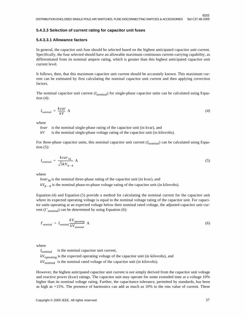
IEEEDISTRIBUTION ENCLOSED SINGLE-POLE AIR SWITCHES, FUSE DISCONNECTING SWITCES & ACCESSORIES Std C37.48-2005
5.4.3.3 Selection of current rating for capacitor unit fuses
5.4.3.3.1 Allowance factors
In general, the capacitor unit fuse should be selected based on the highest anticipated capacitor unit current.Specifically, the fuse selected should have an allowable maximum continuous current-carrying capability, asdifferentiated from its nominal ampere rating, which is greater than this highest anticipated capacitor unitcurrent level.
It follows, then, that this maximum capacitor unit current should be accurately known. This maximum cur-rent can be estimated by first calculating the nominal capacitor unit current and then applying correctionfactors.
The nominal capacitor unit current (Inominal) for single-phase capacitor units can be calculated using Equa-tion (4):
A (4)
wherekvar is the nominal single-phase rating of the capacitor unit (in kvar), andkV is the nominal single-phase voltage rating of the capacitor unit (in kilovolts).
For three-phase capacitor units, this nominal capacitor unit current (Inominal) can be calculated using Equa-tion (5):
A (5)
wherekvar3φ is the nominal three-phase rating of the capacitor unit (in kvar), and
kVφ – φ is the nominal phase-to-phase voltage rating of the capacitor unit (in kilovolts).
Equation (4) and Equation (5) provide a method for calculating the nominal current for the capacitor unitwhere its expected operating voltage is equal to the nominal voltage rating of the capacitor unit. For capaci-tor units operating at an expected voltage below their nominal rated voltage, the adjusted capacitor unit cur-rent (I 'nominal) can be determined by using Equation (6):
A (6)
whereInominal is the nominal capacitor unit current,
kVoperating is the expected operating voltage of the capacitor unit (in kilovolts), and
kVnominal is the nominal rated voltage of the capacitor unit (in kilovolts).
However, the highest anticipated capacitor unit current is not simply derived from the capacitor unit voltageand reactive power (kvar) ratings. The capacitor unit may operate for some extended time at a voltage 10%higher than its nominal voltage rating. Further, the capacitance tolerance, permitted by standards, has beenas high as +15%. The presence of harmonics can add as much as 10% to the rms value of current. These
InominalkvarkV
-----------=
Inominal
kvar3φ
3kVφ φ–
-----------------------=
I'nominal Inominal
kVoperating
kVnominal----------------------=
Copyright © 2005 IEEE. All rights reserved. 37
IEEEStd C37.48-2005 IEEE GUIDE FOR THE APPLICATION, OPERATION, AND MAINTENANCE OF HIGH-VOLTAGE FUSES
factors, taken together, would require that the nominal capacitor unit current, calculated based on rated volt-age and kvar, be increased by an allowance as high as 39% (l.1 × 1.15 × 1.1 = 1.39).
In practice, however, the operating variables described previously rarely attain the maximum values listed,and it is even less likely that they will all be at their maximum values at the same time. Consequently, somepresently used allowances are as low as 22% for ungrounded banks and 31% for grounded banks. Capacitorbanks for certain types of industrial users, on the other hand, may have currents of high harmonic content.Sufficient allowance must be factored in for these cases.
A further factor needs to be considered while selecting the current rating of a capacitor unit fuse. Whencapacitor units are paralleled within a capacitor bank and a full-fault occurs in one of the capacitor units,there is an energy discharge out of the other parallel-connected capacitor unit into the faulted capacitor unit.The discharge consists of a damped high frequency current whose characteristics depend upon such factorsas capacitor bank construction (number, rating, and spacing of capacitor units) and the location of the faultedcapacitor unit. The capacitor unit fuses of capacitor units connected in parallel with the faulted capacitorshould be capable of withstanding this outrush current without melting and without damage that would altertheir time-current-characteristics (TCC). Some manufacturers may limit the application of certain fuses toavoid this type of damage.
For some current-limiting fuses the current rating may be dictated by the level of inrush and outrush currentsoccurring during operation of the capacitor bank, and by how frequently the capacitor bank is switched. Theapplication data of the fuse manufacturer should be consulted for the selection of fuses for frequentlyswitched back-to-back capacitor bank applications, or capacitor bank applications where a large number ofnearby faults are expected.
5.4.3.3.2 Adjustment for ambient temperature
Some fuse manufacturers publish a maximum allowable continuous current-carrying capability for eachampere rating based on a 25 °C or 30 °C ambient temperature. Continuous-current-carrying capabilities ofthese fuses should be reduced to reflect operation in ambient temperatures as high as 40 °C (the recom-mended maximum operating temperature for capacitors).
5.4.3.4 Selection of rated interrupting current for capacitor unit fuses
Capacitor unit fuses may be required to interrupt capacitive type fault currents. With some bank configura-tions and some fault conditions they may also be required to interrupt inductive type fault currents. Thecapacitive and inductive fault current interrupting ratings for capacitor unit fuses should be equal to orgreater than the maximum fault current of each type that is available at the fuse location. Both types of faultcurrent interrupting ratings are specified in symmetrical amperes and are directly comparable to the calcu-lated values of each type that is available at the capacitor fuse location.
Capacitive current faults occur when there is some amount of capacitance that remains in series with the fuseas it is interrupting the circuit. A typical minimum capacitive type current the fuse may be required to inter-rupt can occur when there is progressive pack failures within the capacitor unit and the fuse is sized torespond prior to complete capacitor unit failure. A typical maximum capacitive type current the fuse may berequired to interrupt can occur with a capacitor bank that has an ungrounded-neutral and only one seriesgroup of many parallel connected capacitors per phase. This current is three times the normal bank currentand occurs if the failing capacitor unit is fully faulted. This maximum capacitive current to be interruptedcould be as high as 50 times the normal capacitor unit current if it is a large bank with many parallel capaci-tor units.
On systems where inductive fault currents can occur, (such as wye-connected single series group capacitorbanks with a grounded neutral and/or a grounded capacitor bank frame, or single series group delta con-nected banks) the maximum inductive fault current available at the bank location requires consideration. For
38 Copyright © 2005 IEEE. All rights reserved.

IEEEDISTRIBUTION ENCLOSED SINGLE-POLE AIR SWITCHES, FUSE DISCONNECTING SWITCES & ACCESSORIES Std C37.48-2005
the wye-connected banks listed previously, the fault current will be the available phase-to-neutral faultcurrent, and for the delta bank it will be the available phase-to-phase fault current. Fuses are rated for theirinterrupting capability in symmetrical amperes.
If the available inductive-fault current at the capacitor fuse location exceeds the interrupting rating of anexpulsion-type unit fuse, a current-limiting unit fuse may be used.
For applications where capacitor units are used in enclosures or vaults and capacitor unit fuses are required,current-limiting fuses should be used.
5.4.3.5 Capacitor unit rupture protection for capacitor banks protected by capacitor unit fuses
In addition to consideration of the fuse rated maximum interrupting current, proper capacitor unit fuse selec-tion will also consider the maximum fault current that the capacitor unit can withstand without rupturing.
Capacitor units consist of series and parallel packs within a metal case that is filled with a dielectric fluid.The packs usually consist of metal foil electrodes and a film dielectric. Capacitor unit failure typicallybegins with the failure of a single pack. When this pack fails and shorts out, the voltage across and the cur-rent through the remaining packs increase. The increased stress causes additional packs to fail. If the failureprocess is allowed to continue, it will result in all of the capacitor unit series packs shorted. Other capacitorunit failures may be caused by improper internal connections or dielectric failure to the case. Capacitor unitfailure may lead to case rupture.
When the capacitor unit is completely shorted, the power-frequency current through it depends upon variousfactors. For example, in a single series group grounded-wye bank applied on an effectively grounded systemor a single series group delta bank, the current will be the system inductive fault current that is available atthe bank location. With multiple series group capacitor banks or ungrounded-wye-connected banks, thepower-frequency current will be the available capacitive current that is allowed by the capacitors that remainin the circuit.
To determine case rupture protection, the total clearing curve for the fuse or fuse link is compared to thecapacitor unit’s case rupture curve. The currents for both of these curves are expressed in symmetrical val-ues. The degree of case rupture protection will be dependent on the fuse’s current rating and the shape of itstime-current characteristic curve. Protection is obtained if the total clearing curve of the fuse is to the left ofand below the capacitor unit’s case rupture curve.
For expulsion or other types of non-current-limiting fuses, the lower part of the total clearing curve turns andbecomes asymptotic with the 0.8 cycle (0.013 s for 60 Hz) line. Therefore, a fuse curve that is otherwise tothe left of the capacitor case rupture curve will always intersect with the case rupture curve at this time. Thisintersection delineates the highest available symmetric fault current for which the fuse will protect thecapacitor unit from case rupture. To avoid case rupture when using these types of fuses, the capacitive cur-rent or inductive current available at the fuse location should be less than this value.
For inductive fault currents, the symmetrical current available at the bank should be used instead of theasymmetrical current available. This is an acceptable practice for rupture protection comparisons sincecapacitors usually will degenerate into a total unit failure at or near a peak voltage, thereby producing a sym-metrical current fault.
If the bank can be subjected to inductive type fault currents and these fault currents exceed the capacitor unitwithstand level, the system fault current can be limited by the use of current-limiting fuses. Protection in thearea where the clearing time of the current-limiting fuse is greater than 0.010 s is determined by comparingthe total clearing curve of the fuse to the capacitor unit’s case rupture curve. Protection is obtained in thisarea if the total clearing curve of the fuse is to the left of and below the capacitor unit’s case rupture curve.
Copyright © 2005 IEEE. All rights reserved. 39

IEEEStd C37.48-2005 IEEE GUIDE FOR THE APPLICATION, OPERATION, AND MAINTENANCE OF HIGH-VOLTAGE FUSES
Generally when a current-limiting fuse is properly selected for capacitor case rupture protection for currentlevels below the current-limiting fuse’s 0.010 s total clearing current, the current-limiting action of the cur-rent-limiting fuse will also provide adequate case rupture protection at higher currents. In the event thatextrapolation of the curves up to the maximum short circuit current available at the capacitor bank locationindicates possible intersection, the capacitor and fuse manufacturers should be consulted. An example of acapacitor case rupture curve characteristics is shown in Figure 4.
Many station banks have multiple series groups or other configurations such that capacitance remains in thecircuit when a single capacitor unit fails. Since these fault currents are relatively small as compared to induc-tive system faults, a current-limiting fuse is not normally required to limit available fault current.
The use of current-limiting fuses as a capacitor unit fuse is normally limited to the following:
a) Wye-connected single series group capacitor banks with a grounded neutral and/or a groundedcapacitor bank frame, or a single series group delta connected bank
b) Metal-enclosed banks because of their non-gassing operation
c) Applications where the discharge from many parallel units has enough energy that it exceeds thedischarge interrupting capacity of expulsion fuses or the withstand ability of the capacitor unit cases
Capacitor manufacturers should be able to provide the case rupture curves (tank rupture curves) mentionedabove and/or provide additional information or assistance regarding the protection of their capacitor units.The fuse total clearing curves are available from the fuse manufacturer.
5.4.3.6 Selection of the capacitor unit fuse for discharge-energy withstand
If a capacitor unit failure occurs in a capacitor bank, where the capacitor units are protected by unit fuses, theenergy stored in the parallel connected unfaulted capacitors will discharge through the unit fuses on theseunits and into the failed capacitor unit and its fuse. For the calculation of stored energy, see the definition ofcapacitor stored energy in IEEE Std C37.40-2003.
The capacitor unit fuse of a fully-faulted capacitor unit that is part of a parallel-group of other capacitorsunits must be able to operate and withstand, without bursting during operation, the outrush current from thehealthy parallel capacitors as they discharge into the faulted capacitor unit. The energy stored in the parallelconnected capacitor units is available to be absorbed by the fuse and the faulted capacitor unit. While thefuse itself may absorb only a portion of the total energy available in the parallel-connected capacitor units,the withstand requirement for the fuse is determined by the total energy that is available for this discharge.
Capacitor units also have a discharge-energy withstand capability that is related to their construction. If thecapacitor bank design can produce a total discharge-energy that is equal to or less than the withstandcapability of the capacitor units, then the fuse is not required to limit the discharge. A fuse with a discharge-energy rating equal to or exceeding this total discharge-energy should be selected without regard to currentlimitation.
If a capacitor bank design has the capability to discharge more energy than the capacitor units can withstand,then the use of current-limiting fuses should be considered. Current-limiting fuses are capable of limiting thedischarge energy from adjacent parallel connected capacitor units into the faulted capacitor unit. For properprotection of the capacitor unit from the discharge energy of the parallel capacitor units, the maximum let-through I 2t of the fuse should be less than the withstand I 2t of the capacitor unit. For specific guidelines inthis area, the capacitor and fuse manufacturers should be consulted.
Other methods that can be used to eliminate excessive discharge energy are as follows:
a) To use more series groups and less parallel units
b) To use two smaller parallel capacitor banks
40 Copyright © 2005 IEEE. All rights reserved.

IEEEDISTRIBUTION ENCLOSED SINGLE-POLE AIR SWITCHES, FUSE DISCONNECTING SWITCES & ACCESSORIES Std C37.48-2005
The discharge-energy rating for a capacitor unit fuse is the maximum stored energy at rated voltage withwhich the fuse will be required to operate and successfully interrupt the circuit. Typical discharge-energyratings for expulsion-type capacitor unit fuses range from 10 kJ to 30 kJ. The application of these fuses maybe limited to less than the maximum discharge energy rating of the fuse by the withstand capability of thecapacitor unit. The rating for current-limiting capacitor unit fuses are usually 40 kJ or higher.
6. Operation guidelines for various fuse types
6.1 Use of nonexpendable cap on expendable-cap cutouts
Installation of nonexpendable cap on an expendable-cap cutout results in a reduction of the expendable-capcutout interrupting capability.
Refer to manufacturers’ instructions as to the reduction in the rating.
6.2 Operating speed
Any of the devices that are designed to disconnect or close an energized circuit should be operated in arapid, positive manner since the success of this function may be dependent upon the use of proper procedureand technique as established by the manufacturer.
6.3 Locking or latching of fuses, blades, or links in closed position
Special care should be taken to see that the fuse, blade, or link is securely locked, latched, or held fast in theclosed position as recommended by the manufacturer. The fuse carrier assembly of distribution oil fuse cut-outs or other devices applied in sealed enclosures should be locked and sealed; therefore, the sealing gasketsmust be maintained in good condition for satisfactory operation.
6.4 Fuseholder position
Certain types of outdoor fuses should not be left hanging in the open position as a means of isolating theequipment from the system since rain water may collect in the fuse tube and cause swelling or other damage,thus impairing the interrupting capability of the fuse. If an equipment installation or a circuit is to be left outof service, the fuseholders may be hung upright from a pin or hook on the pole.
6.5 Voltage withstand of blown fuses
Many fuse cutouts and other “drop-open” fuses are designed to incorporate a drop-open action following aninterrupting operation. This action quickly removes all voltage stress across the fuse holder.
Many applications of non-drop-open fuses, such as the backup current-limiting type, utilize a series expul-sion fuse, or other device coordinated to provide isolation means to prevent possible dielectric breakdown ofa contaminated non-drop-open fuse if subjected to long-time voltage stress. Also, many capacitor unit fuseshave a disconnector that removes any long-term voltage stress from a blown fuse.
For those applications where long-time voltage stress can occur across a blown fuse, and dielectricbreakdown would permit resumption of current flow, the fuse manufacturer should be consulted as to theadequacy of the proposed fuse for this application.
Copyright © 2005 IEEE. All rights reserved. 41

IEEEStd C37.48-2005 IEEE GUIDE FOR THE APPLICATION, OPERATION, AND MAINTENANCE OF HIGH-VOLTAGE FUSES
6.6 Replacement and handling of fuses
Replacement fuses should be those recommended by the manufacturer. Care is particularly required in cer-tain applications, see 4.8.5 and 5.1.3.1.4.
6.6.1 Replacement of fuses
Replacement of fuses should be done with the circuit de-energized, unless their design, testing, and the man-ufacturer’s recommendations permit replacement while energized. In the case of fuses that are under thecontrol of a utility, fuse replacement should be done using utility practices developed in conjunction with thefuse’s manufacturer. However, expulsion fuses should never be replaced from within the venting area withthe circuit energized.
6.6.2 Handling of current-limiting fuses
Careless handling of current-limiting fuses may result in damage to the fuse. This damage may be clearlyvisible, such as denting of the fuse cap or cracking or breakage of the fuse tube. On the other hand, it may beinvisible—such as breakage of an element inside the fuse or disruption of a seal in an under-oil fuse. Thisdamage can interfere with key performance requirements placed on the fuse, that is a damaged fuse may notbe able to carry its rated continuous current or it may not be able to interrupt a faulted circuit. If eitheroccurs, other equipment, as well as those working on the equipment, can be affected adversely.
Some typical causes of damage include, but are not limited, to the following:
— Dropping or mishandling a fuse
— Excessive force in closing a fuse into its mounting
— Improper alignment of the fuse with its fuse support during insertion or removal
— Over-tightening connection points
— Excessive lead size or weight causing too high a cantilever force being placed on a fuse
— Using a fuse in a thermal environment beyond its rating.
The manufacturer should be consulted as to proper installation force and acceptable mountings as well assafe handling guidelines. If damage is suspected, the fuse should be removed from service.
6.6.3 Fuses subject to partial melting or deterioration
There are fuse constructions that are subject to partial melting or damage by current that is not of sufficientmagnitude and time to cause total melting of the fuse. For such fuses, it is important that the following pre-cautions be observed:
a) In two- or three-phase applications it is advisable to replace the fuse units (or fuse links) in allphases when the fuses in one or more phases are found to have blown unless
1) The manufacturer’s instructions are followed for determining the suitability of the fuse(s) forcontinued service.
2) There is proof that no damaging current occurred in the remaining phase(s).
b) In applications where these fuses are used in series with other fuses or interrupting devices in thesame phase in such a manner that their melting or clearing curves cross one another, or both, it isadvisable after an operation to follow carefully the manufacturer’s instructions for determining thesuitability of the fuse(s) for continued service.
42 Copyright © 2005 IEEE. All rights reserved.

IEEEDISTRIBUTION ENCLOSED SINGLE-POLE AIR SWITCHES, FUSE DISCONNECTING SWITCES & ACCESSORIES Std C37.48-2005
6.6.4 Re-energization after fuses have blown
It is advisable to locate and correct the situation that caused the fuse to operate before re-energizing. Theoperator should be aware that a potential hazard may exist if the circuit is re-energized with the fault condi-tion still present.
6.7 Replacement of exhaust control device
The exhaust-control device on the fuse may be suitable for reuse after a fuse operation. This is dependentupon the fault magnitudes, and numbers of fault-current interruptions it has experienced. It is advisable,after the operation of a fuse, to inspect the exhaust-control device and follow carefully the manufacturer’sinstructions for determining the suitability of the device for further service.
6.8 Operation of energized fuses
A fuse or piece of fused equipment not equipped with a means of breaking load should not be opened unlessthe fuse has blown or the circuit has been de-energized.
When a fuse or piece of fused equipment equipped with a means of breaking load is used, it should not beopened immediately after the circuit has been energized. The time delay before opening will vary consider-ably, depending upon the continuous current rating of the fuse, but should be adequate to allow the fuse tointerrupt any existing fault current that might exceed the load-break rating of the device. For large-sized fuselinks above 100 amperes, this time delay could be as long as 10 min.
6.9 Storing spare fuse units and replaceable parts
Spare fuse units and replaceable parts of fuse units should be stored in such a manner that they will not bedamaged, and will be available when needed. If several types and ratings of fuses are used in a givenlocation, the spare parts should be suitably marked, coded, or indexed to show the mountings, circuits, orequipment with which they are to be used. This will minimize the possibility of improper use. Consult themanufacturer for recommendations.
7. Additional operation guidelines for specific devices
The following operational guidelines are in addition to those in Clause 6.
7.1 Capacitor fuses
7.1.1 General operating requirements for capacitor fuses
The fuse should be capable of carrying normal capacitive currents including currents above capacitor ratedcurrent that results from system overvoltage, system harmonics, or higher than rated capacitance.
The fuse should also be capable of carrying transient currents that can normally occur in capacitor banks.
Care should be taken to discharge the capacitors after de-energization, and to ground the entire capacitorbank before any maintenance is performed. Refer to 5.4 for complete capacitor fuse application guidelines.
Copyright © 2005 IEEE. All rights reserved. 43

IEEEStd C37.48-2005 IEEE GUIDE FOR THE APPLICATION, OPERATION, AND MAINTENANCE OF HIGH-VOLTAGE FUSES
7.1.2 Capacitor fuse replacement
Fuses used on capacitor units should not be handled, removed, or replaced unless due precautions are takenbeforehand to de-energize, discharge and ground the capacitor units. The entire capacitor bank should be de-energized and grounded while replacing capacitor-unit fuses. Capacitor line fuses may be handled usinglive-line tools.
Capacitor units used in power applications usually have a discharge resistor to reduce the capacitor unit volt-age to a specified value in a specified time after being de-energized. This internal-discharge device shouldnot be considered as a substitute for the recommended safety practice of manually discharging the residualstored energy before working on capacitor units. Capacitor units may be damaged if discharged too soonafter being de-energized. It is recommended that at least 5 min be allowed for adequate discharge throughthe discharge resistor, and then the capacitor terminals should be shorted together and connected to ground.Refer to IEEE Std 18-2002 or NEMA CP 1-2000 for complete information in regard to discharging ofcapacitor units.
When installing or removing capacitor unit fuses, the fuse link leader should first be disconnected from thecapacitor bushing to avoid twisting of the fusible element.
When replacing a capacitor unit fuse, it may be desirable to check the continuity and the condition of thefuses or fuse links on adjacent parallel capacitor units.
7.2 Liquid-submerged expulsion fuses in enclosures
7.2.1 Liquid in which the fuse is submerged
The liquid is an integral part of the equipment design and the fuse performance, and manufacturer’s recom-mendations should be followed.
The operation of the fuse may cause carbon to form in the liquid. The degree to which this will affect theequipment characteristics depends upon the number of operations as well as their magnitude and duration.Operating experience will usually be the best basis for establishing a maintenance schedule. See Clause 8and Clause 9 for additional information.
7.2.2 Removal and replacement of fuses
A sealed enclosure (tank) may have a pressure greater than atmospheric. This internal pressure should bereturned to atmospheric pressure prior to removing fuses.
8. Maintenance for all fuse types
8.1 Safety precautions
Examination and maintenance of equipment that is connected to an energized circuit should be done at a safedistance from any exposed energized parts of equipment or conductors, or the circuit and equipment shouldbe de-energized. In the case of equipment on capacitor installations, precautions should be taken to dis-charge the capacitors after de-energization. Alternatively, live line techniques may be employed if they areadequate to ensure safety to personnel.
44 Copyright © 2005 IEEE. All rights reserved.

IEEEDISTRIBUTION ENCLOSED SINGLE-POLE AIR SWITCHES, FUSE DISCONNECTING SWITCES & ACCESSORIES Std C37.48-2005
8.2 Frequency of maintenance
All fuses should be maintained in accordance with the manufacturer’s recommendations.
8.3 Inspection of fuse or switching device.
Equipment within the scope of this guide usually consists of several parts, some current-carrying and somenon-current-carrying, all subject to atmospheric and other environmental conditions. The equipment is alsosubject to the normal and abnormal operating conditions of the system in which it is connected. The fre-quency and completeness of inspection will necessarily be a function of the service reliability required andthe conditions at the specific equipment location and must be determined by the user. Some of the items thatshould be considered are as follows:
a) The equipment should be given a general examination for obvious defects and to ensure that bolts,nuts, washers, pins, and terminal connectors are securely in place and in good condition.
b) Insulators and other porcelain or plastic parts should be inspected for breaks, cracks, burns, orcontamination. Insulators and other insulating surfaces should be cleaned of any excessive contami-nation, such as salt deposits and cement or road dust, to avoid flashover as a result of the accumula-tion of foreign substances on their surfaces. Cracked or broken insulators and other insulating partsshould be replaced. To prevent flashover, consideration should be given to replacing badly burnedinsulating parts.
c) Current-contact surfaces should be examined for pitting, burning, alignment, and to ensure that thecontacts when closed are held together with adequate pressure. Badly pitted, burned, or distortedcontacts should be replaced. Alignment and spring pressure should be adjusted if required.
d) Vent holes on equipment so equipped should be examined to ensure the holes are not plugged withdirt or other foreign substances, and cleaned if necessary.
e) If applicable to the equipment, the fuse unit or fuse tube and renewable element should be examinedfor corrosion of the fuse element or connecting conductors, excessive erosion or delamination of theinside of fuse tubes, tracking and dirt on the outside of the fuse tube, and improper assembly thatmay prevent proper operation. Components showing significant signs of deterioration should bereplaced. Fuse tubes made of organic material may be refinished according to manufacturer’sspecifications.
f) Current-carrying parts, such as blades or fuse links, should be examined for thermal damage result-ing from heavy short-circuit currents or overloads. Damaged fuse links and other parts significantlydeformed should be replaced.
g) The mechanical operation should be checked per manufacturer’s recommendations.
8.4 Inspection of fuse links in distribution cutouts
Fuse links in distribution cutouts may require periodic replacement since corrosion of the lower terminal ofthe fuse link (generally a flexible cable) at the lower open-end of the fuse holder may cause breakage ormelting at this point rather than at the current-responsive element. Link-break cutouts are more susceptibleto this problem because of the mechanical strain placed upon the fuse link by the link-break mechanism.
9. Additional maintenance guidelines for specific devices
9.1 Capacitor fuses
Care should be taken to discharge and ground capacitors before maintenance is performed. See 7.1.2 for fur-ther information.
Copyright © 2005 IEEE. All rights reserved. 45

IEEEStd C37.48-2005 IEEE GUIDE FOR THE APPLICATION, OPERATION, AND MAINTENANCE OF HIGH-VOLTAGE FUSES
9.2 Liquid-submerged expulsion fuses in enclosures
The following is additional requirement for liquid-immersed fuses.
9.2.1 Liquid
The level and quality of the liquid in the equipment may affect the performance of the expulsion fuse. Allgasketed joints and seals should be properly maintained.
Inspection should include checking the tank for liquid leakage and for indications of any external damage ordeterioration. The level of the liquid should be checked to see that it is in accordance with the switchgearmanufacturer’s recommendation. Liquid should not be withdrawn from, or added to, the switchgear while itis energized unless there is a suitable means or procedure for this function.
9.2.2 Inspection of fuse components
Manufacturer’s recommendations and requirements for inspection and maintenance of fuse componentsshould be followed. Replacement fuses should be those recommended by the switchgear manufacturer.Many users have established procedures to allow inspection and maintenance of energized equipment. In theabsence of such procedures, the equipment should be de-energized before performing any inspection ormaintenance.
The following are some general guidelines for inspecting and maintaining fuse components:
a) All current-carrying components of a fuse carrier or bayonet assembly should be inspected. Anycomponents showing indication of excessive heating or damage from arcing should be replaced.Excessive arc damage or heating of contact surfaces may indicate the need to inspect internal con-tacts. This generally requires removing the unit from service.
b) Any fuse carrier or cartridge showing signs of cracks, erosion, tracking, or excessive wear should bereplaced.
c) All seals and gaskets should be checked and any that are deteriorated or deformed should bereplaced. Manufacturer-approved replacements should be used.
d) Electrical connections should be checked to determine that they are clean and tightly secured.
e) Satisfactory condition of the fuse should be verified, as recommended by the manufacturer.
46 Copyright © 2005 IEEE. All rights reserved.

IEEEDISTRIBUTION ENCLOSED SINGLE-POLE AIR SWITCHES, FUSE DISCONNECTING SWITCES & ACCESSORIES Std C37.48-2005
Annex A
(informative)
Bibliography
[B1] ANSI C37.42-1996, American National Standard Specifications for High Voltage Expulsion Type Dis-tribution Class Fuses, Cutouts, Fuse Disconnecting Switches and Fuse Links.
[B2] ANSI C37.45-1981 (Reaff 1992), American National Standard Specifications for High Voltage Distri-bution Class Enclosed Single-Pole Air Switches.
[B3] ANSI C37.53.1-1989, American National Standard for Switchgear – High-Voltage Current-LimitingMotor-Starter Fuses—Conformance Test Procedures.
[B4] IEEE Std C37.100™-1992, IEEE Standard Definitions for Power Switchgear.
[B5] IEEE Std 1036™ -1992, IEEE Guide for Application of Shunt Power Capacitors.
Copyright © 2005 IEEE. All rights reserved. 47