Embed Size (px)
Citation preview
)PC FILE COPYNaval Research LaboratoryWashington, DC 20375.5000
NRL R 9271
CAD/CAM Feasibility Study
N LYNN M. KEUTHAN
N ~Mdps Elecronic Warfare Systems BrammTactical Elecronic Warfare Division
II0I
SEP 1, 1990DTD
9 0 0 912 02,2
- for pubice w~rn ditvkbuton ub
1 Form ApprovedREPORT DOCUMENTATION PAGE oMB No.04o
Public reporting burden for this collection of information is estimated to average 1 hour per response, including the time for reviewin structions,. searching existing data sources,gathering and maintaining the data needed, and competing and reviewing the collecton of Information Send comments retgrding this burden estimate o any other aspect of thiscollection of information, including suggetions for reducing this burden, to Washington Headguarters Services. Oirectorate for Information Operatlons and Rea orS. 12 IS JeffersonOavis Highway. Suite 1204, Arlington, VA 22202-4302. and to the Office of Management and Budget. Paperwork Reduction Project (0704.0 18), Washington. DC 20503.
1. AGENCY USE ONLY (Leave blank) 2. REPORT DATE 3. REPORT TYPE AND DATES COVEREDSeptember 11, 1990 Final 1987-1990
4. TITLE AND SUBTITLE 5. FUNDING NUMBERS
CAD/CAM Feasibility Study PE - 64255NPR - W0672
6. AUTHOR(S) WU - DN 120-188
Lynn M. Keuthan
7. PERFORMING ORGANIZATION NAME(S) AND ADDRESS(ES) S. PERFORMING ORGANIZATIONREPORT NUMBER
Naval Research Laboratory NRL Report 9271Washington, D.C. 20375-5000
9. SPONSORING /MONITORING AGENCY NAME(S) AND ADDRESS(ES) 10. SPONSORING/ MONITORINGChief of Naval Research (ONR) AGENCY REPORT NUMBER
Arlington, VA 22217-
Naval Air Systems Command (NAVAIR)Washington, D.C. 20361-8030
11. SUPPLEMENTARY NOTES
12a. DISTRIBUTION / AVAILABILITY STATEMENT 12b. DISTRIBUTION CODE
Approved for public release; distribution unlimited.
/
13. ABSTRACT (Maximum 200 words)
-' This report addresses the effectiveness and capabilities of computer-aided design and digitial and analogsimulation in an R&D microprocessor environment. The range of tools available, present capabilities ofCAD/CAM systems, and complex modeling features are presented and explained. Advanced computer-aidedengineering and simulation tools may assist in testing new theories and developing complex hardware andsoftware systems in a more expedient manner. .- . ----
, /
14. SUBJECT TERMS 15. NUMBER OF PAGESComputer-aided design Computer-aided engineering 68Digitial simulation Fault simulation 16. PRICE CODEAnalog simulation '-Hazard analysis ( ' t (
17. SECURITY CLASSIFICATION 1B. SECURITY CLASSIFICATION 19. SECURITY CLASSIFICATION 20. LIMITATION OF ABSTRACTOF REPORT OF THIS PAGE OF ABSTRACTUNCLASSIFIED UNCLASSIFIED UNCLASSIFIED UL
NSN 7540-01-280-5500 Standard Form 298 (Rev 2-89)Prescribed by ANSI SId 139-18298.102
CONTENTS
FOREWORD .................................................................................... 1
GENERAL ...................................................................................... 2
CRITERIA....................................................................................... 2
Companies Polled......................................................................... 3Demonstrations and Comparisons ..................................................... 3Comparison of Companies ............................................................ 3Companies Meeting Fewer Requirements.............................................. 6
PC-Based Systems........................................................................ 7Additional Companies..................................................................... 8Logic Simulation Systems................................................................. 9
Available Logic Simulators ........................................................... 10Physical Modeling Capabilities........................................................ 10
Printed-Circuit-Board Work Systems...................................................... 12
STANDARDS.................................................................................... 12
TESTING INTERFACES........................................................................14
DOCUMENTATION ............................................................................ 14
PROPOSED SOLUTIONS ....................................................................... 15
Proposed Solution Number One .......................................................... 15Proposed Solution Number Two .......................................................... 16Proposed Solution Number Three ......................................................... 16
PRICE/PERFORMANCE FOR THREE PROPOSED SYSTEM SOLUTIONS.................... 17
SYSTEM MAINTENANCE...................................................................... 17
RESULTS OF EVALUATION OF TERADYNE'S CAD/CAM SYSTEM ........................ 18
Background............................................................................... 18Goals of the Evaluation .................................................................. 18
DETAILED DISCUSSION OF GOALS .......................................................... 19
Goal Number One ........................................................................ 19Goal Number Two ....................................................................... 19Goal Number Three ...................................................................... 20
111
Goal Number Four.......................................................................26Goal Number Five ....................................................................... 27Goal Number Six......................................................................... 27Goal Number Seven...................................................................... 27Goal Number Eight.......................................................................28Additional Results of Evaluation.......................................................... 28
SUMMARY...................................................................................... 33
ACKNOWLEDGMENTS........................................................................33
LITERATURE OBTAINED ..................................................................... 33
ABBREVIATIONS AND ACRONYMS .......................................................... 34
APPENDIX A - Directory of Vendors........................................................... 37
APPENDIX B - Request-for-Information (RFI) Letter............................................41
APPENDIX C - CAD/CAM Requirements...................................................... 43
APPENDIX D - Internal NRL Memorandum ................................................... 45
APPENDIX E - Comparison Charts............................................................. 47
APPENDIX F - Comparison Graphs............................................................53
APPENDIX G - Relative Pricing................................................................ 55
APPENDIX H - Application Note............................................................... 57
APPENDIX I - Worst-Case Timing Analysis Ensures Board Reliability.........................63
D1C TABIunarino. c"L
Distribution I
Av.aiatilitY Codes
's Iu ' Avail
3!id 10f
Dist
iv
CAD/CAM FEASIBILITY STUDY
FOREWORD
As research progresses and relies on advanced technological tools and as researchers designsystems to test theories and to compare techniques, it becomes necessary to expedite the design cycle andto minimize divergences from the central issues of the research programs. For research areas that relyon highly computative processes, digital signal processing (DSP) calculations, and analog waveforms,digital and analog simulation techniques can provide the needed vehicle for analysis.
Digital and analog simulation techniques can be applied to devices ranging from simple logic gatesand operational amplifiers to advanced versions of microprocessors and complicated feedback systems.Digital simulation becomes especially valuable when considering complex logic and timing across a boardor system level.
In such complex systems, timing problems may occur only when devices operate at the leadingedge of the manufacturers' specifications. Likewise, when possible timing hazards are considered, asimulator must distinguish between possible timing problems and problems that would never occurbecause of gate propagation, common signal origination, or other properties of digital hardware.
The value of digital simulation also becomes obvious when considering the hazards arising froma combination of signals with unknown states, pulses wider than the delay time of a gate, or acombination of both. When a digital simulation system can describe these hazards, pinpoint theorigination, and determine whet&.er these hazards persist over a period of time, then the system becomesa reliable and powerful tool for supporting advanced research.
In addition, systems with digital and analog or radio-frequency microwave parts can be difficultto characterize without the use of advanced simulation tools. These complex systems are used, forexample, to analyze and develop tracking radar systems. Advanced simulation provides a means forcomparing different electronic countermeasure (ECM) techniques.
After comparing a spectrum of designs in simulation, a computer-aided design/computer-aidedmanufacturing (CAD/CAM) system can readily take the design to printed-circuit-board (PCB) layout.With the proper CAD/CAM equipment, the engineer or researcher can take a design to PCB layout ina relatively small percentage of time and effort.
Simulation results can provide more design reliability than wire-wrap prototypes or even morethan the use of a prototype PCB. Further, simulation makes possible the use of new theories and techni-ques in a testing mode sooner for real world applications and thus provide reliable systems in anexpedient manner.
Manuscript approved April 17, 1990.
LYNN M. KEUTHAN
A designer can spend an appreciable amount of time just in comparing the burgeoning numberof CAD/CAM systems available today. Considerable additional time is also required to point out themain features and drawbacks in each system investigated. These procedures have already been carriedout in this study. This report includes significant features and explanations of the capabilities of thevarious available packages used in computer-aided design (CAD).
GENERAL
Computer-aided design and computer-aided manufacturing are subsets of computer-aidedengineering (CAE). This report outlines the results of an extensive study on CAD/CAM/CAE systems.Having accepted these definitions, liberty is taken in this report to interchange CAD/CAM and CAE.The report contains a listing of certain companies identified as possible CAD/CAM vendors. Alsoincluded is a listing of requirements desired in a computer-aided engineering system.
This report identifies companies that are possible CAD/CAM vendors. A listing of requirementsdesired in a CAE system is also included. Companies that responded to the feasibility study inquiriesare identified. Comparisons are made across all desired criteria for the respondents, and threeCAD/CAM solutions are identified with recommendations. These three are compared. Finally, the resultsof an evaluation of one particular CAD/CAM solution are outlined considering the needs of the NavalResearch Laboratory (NRL).
CRITERIA
Having considered all phases of CAD, a list of requirements was developed for CAD/CAMsystems. Table 1 lists these phases.
Table 1 - CAD Phases Considered inDeveloping Requirements
Schematic Entry User Interface*Logic Simulation System IntegrationPrinted-Circuit-Board Maintenance*
(PCB) Design Vendor Support*Training Design DocumentationSystem Upgrade*
*Critical areas of concern
To the critical areas of concern listed in the table we must add price per performance. Becauseof the volatility of the CAD/CAM market and the ongoing state of the art, the ability to upgrade andvendor support are of primary concern and, as such, were weighted heavily in preparing the final analysisand recommendations.
The impressive number of companies entering and exiting the CAD/CAM market illustrates thetremendous degree of competition in these fields and underlines the amount of resources required fordesigning CAE systems. Overall, however, this market does not seem to favor large companies oversmall ones. Small companies generally offer systems lower in cost than those offered by long establishedcompanies. At this point, the marketplace is consolidating. Company acquisitions in an effort to extendCAD/CAM capabilities or "buy out the competition" actions are numerous. The major CAD/CAMcompanies for higher end systems are becoming more evident. Companies that provide PC-basedpackages are numerous, and no one particular company dominates the market. Considering all factors,
2
NRL REPORT 9271
the choice of a CAE system for which support can reasonably be assured continues to be difficult andcritical.
Companies Polled
The companies polled were principally selected from advertisers in computer magazines over thepast five years. Articles listing manufacturers of CAD/CAM products were obtained primarily from DNUMagazin, Computer D , EDN News, and Electronic Design.
Fifty-seven companies were polled to ascertain whether or not these organizations could meet thedesired requirements for CAE development. These companies (Appendix A) were sent a letter (AppendixB) that stated the objective of the feasibility study and listed the criteria (Appendix C) for the study. Theletter indicates that the survey is for information only, and not a Request for Proposal (RFP).
Twenty-eight companies answered with some sort of response, only slightly less than half thenumber of companies polled. A few of the larger companies, notably Computer Vision, G.E. Calma,Hewlett-Packard, and Tektronix, responded individually to each requirement. However, the majority ofcompanies merely provided available literature; individual requirements were not addressed. Only threecompanies offered products more suited for analog design or analysis: Analog Design Tools,AUTODESK, and Versacad.
Design Computation responded to listed requirements and indicated where their products differedfrom these. This company also demonstrated flexibility in an attempt to meet additional requirementsbeyond their current capabilities.
Great Softwestern responded enthusiastically that "we meet this requirement" but failed to provideany supporting literature to verify the statement. What was submitted by this company appeared tocategorize the company as functioning more in the role of consultant rather than a system manufacturer.No pricing data were supplied.
Demonstrations and Comparisons
Twelve demonstrations of systems were viewed after the inputs from the 28 companies had beenstudied and analyzed. Tektronix was found to meet 99.5% of all the stated requirments, and ademonstration was arranged for NRL's Ships EW Branch and other members of the Tactical ElectronicWarfare Division. (A copy of the memorandum that listed the specifics of items covered by the demonst-raion appears in Appendix D.) The percentages of the requirements fulfilled for the various companieswere compiled and tabulated (Appendix E) and compared graphically (Appendix F.)
Pricing was compared for the 24 companies that provide digital CAD/CAM systems and cross-compared with the percentage of the requirements met. Pricing is based on basic quotations plus anyadditional costs for hardware and physical modeling if available and not included in the basic quotation(Appendix G.)
Comparison of Companies
Five companies were found to meet at least 90% of the identified requirements. In order ofhighest percentage first, these companies are Tektronix, Racal-Redac, Silvar-Lisco, Hewlett-Packard, andTeradyne.
3
LYNN M. KEUTHAN
As an example of the market volatility, mentioned earlier, the CAE Systems Division ofTektronix, whose submittal lacked only the desired resolution, was recently acquired by Mentor Graphics.Previous buyers from Tektronix are being phased over to the new owner in a two-year period as allsystems are integrated.
Since the takeover, Tektronix has continued to work with the Ships EW Branch to make theiroriginal system available at the original price of about $50,000. If the Tektronix system is purchased,Ships EW will be phased over later to Mentor Graphics at no additional cost. The specifics of thetransition to Mentor Graphics remain unclear at this time. The new owner plans to adopt the TektronixASIC and microwave-design systems because the Mentor Graphics company has no comparablecapabilities. Discussions are underway concerning the incorporation of some Tektronix databasefunctionality into the front-end schematic design or, possibly, keeping the Tektronix Database Designer'sSchematic Capture (DDSC) as a separate product. Many customers have bought the latter solely for itsdatabase functionality.
All of these details imply uncertainties in integration in both Tektronix and Mentor Graphicproducts. Even those who currently own the Tektronix CAE system may have to contend with inevitablyhigher maintenance costs and something less than the original Tektronix service.
Racal-Redac, meeting 95% of listed requirements, offers a system for $189,500. This firm hasbeen a major player in CAD/CAM systems for some time and has a steady and well-supported base ofcustomers. A turnkey interface has been maintained to HHB's CADAT (the package known as Visula-CADAT). HHB has added analog simulation capabilities, beginning with the Visula-CADAT version.
Racal-Redac acquired HHB Cadat in 1988. The current company name is Racal-HHB. (Thedirectory in Appendix A lists the headquarters of Racal-HHB as Racal-Redac and the headquarters forthe CADAT simulator as HHB-Cadat.) This was a friendly merger caused by the close existing tiesbetween the companies. Both companies realized a tremendous benefit because of an already existingsoftware interface between Racal-Redac's schematic package and HHB's CADAT simulator. Thissimulator runs on SUN, Apollo, DEC, and PC workstations. Interfaces to HHB CADAT are stillavailable for a number of other packages including those provided by Cadnetix and Computer Vision.
The Racal-Redac system is extremely user-friendly and well integrated. Many industry standardshave been adopted (e.g., NFS and SQL) and it is planned to adopt the X-windows operating system inter-face standard. This system runs on the SUN, Apollo, and VAX workstation platforms. It is extremelyversatile and offers a functional solution at a competitive price.
Silvar-Lisco supplies 92% of the requirements with their CAD/CAM system. Extensive softwarepackages are available for CAE applications. This company is traditionally known for ASIC design ratherthan PCB design and may have geared its products for ASIC design and development.
Silvar-Lisco also compares well in the needed technical requirements for CAD and development.Some concern exists, however, about the availability of reliable support and service. The company seemsto expect the customers to travel to their facility in Nashua, New Hampshire, for product demonstrations.Initially, the company was reluctant to provide any pricing data in the absence of a formal RFP but finallyprovided the information that their software is licensed for a base fee of $79,000 to which $11,850 isadded to cover maintenance. These figures do not include hardware costs, and the charges are assessedon an annual basis.
4
NRL REPORT 9271
Hewlett-Packard, meeting 91% of the stated requirements, offers a well-integrated system forschematic capture, logic simulation, and PCB design. Gen-Rad's HILO-ill is integrated to theirschematic and PCB products to assure logic simulation capability.
The logic simulator HILO-nl addresses each requirement for logic simulation in conjunction witha physical modeler, HI-CHIP. The package is available from Hewlett-Packard for $69,200. Theadditional HILO-Ill cost of the HI-CHIP physical modeler depends on the particular device supportrequired.
Logic Automation intends to support HILO-Ill soon with their physical modelers. GenRad haddiscontinued adding devices and upgrades to their HILO-MI during the last two years, but lately effortshave been resumed in research and development aimed at updating GenRad's model libraries for thisproduct.
Hewlett-Packard also addresses many of the desired features of a CAD/CAM system. Theyprovide excellent front-end database management capabilities not available elsewhere. The designer canadd information fields to a schematic design. However, Hewlett-Packard is lacking in the areas of openarchitecture, versatility, and flexible configuration.
The Hewlett-Packard package runs solely on the HP9000, Model 350 workstation. This closedarchitecture does not allow networking to other workstations or the transferring of files. Not only is thechoice of platforms limited but hardware interfaces are also limited to their own plotter, printer, andsoftware development station. This can add considerable additional expenses in hardware.
At this time, high-quality Houston Instruments plotters and a number of printers have beenprocured and are available to the Ships EW Branch. Additional procurements have been placed forneeded software development tools that were selected as the best technical solution and the most cost-effective. Hewlett-Packard provides no support in addressing interfacing needs to other systems. Adesigner's board-application code can not be easily downloaded to a development station other than onemade by Hewlett-Packard. This vendor's station costs about $60,000.
Without HI-CHIP, Hewlett-Packard's CAD/CAM system can be purchased for $138,411.Although the company claims to be moving more positively in the direction of open architecture, therequirement for interface with their proprietary equipment still exists.
Teradyne meets 90% of specified requirements. They provide extensive and elaborate tools forCAE. Such tools include schematic capture, logic simulation, physical modeling, PCB design, thermalanalysis, and extensive production board testing devices. Teradyne has recently acquired CaseTechnology and AIDA, thereby broadening its base in many phases of CAE.
Teradyne has well-developed business relationships with board-testing and computer-manufacturing companies. These relationships permit the company to address many questions relatingto the interfacing of their equipment (e.g., with Tektronix DAS 9200). Teradyne has also a history ofjoint demonstrations with Digital Equipment Corporation.
Teradyne offers some of the most sophisticated logic and fault simulation tools available.Appendix I provides a selection of their logic simulation features.
Teradyne's logic simulator, LASAR, detects many possible logic-design problems that couldotherwise not be detected until many production boards had been delivered to the field. The cost of this
5
LYNN M. KEUTHAN
system, $180,300, excluding hardware, is justified by the tremendous system features and customersupport available.
Companies Meeting Fewer Requirements
Four more companies meet at least 80% of the listed requirements. With their respectivepercentages these are: Computer Vision, 88%; Mentor Graphics, 87%; G.E. Calma, 82%; and ScientificCalculations, 81%.
Computer Vision, boasting the most sales in CAD/CAM development, supplied the most elaboratedata package. Each requirement was specifically addressed, and prices were given; installation require-ments were defined, and sufficient additional information was provided to enable the actual purchase ofthe package.
The company interfaces with HHB's CADAT for logic simulation. To purchase this packagethrough Computer Vision, the applicable price is $25,000 with an additional $129,059 for the HHB CAThardware modeler. Another additional cost of $99,800 for hardware and software support of PCB designis difficult to justify; the company develops only schematic capture and PCB-design software.
Mentor Graphics has a product that runs on the Apollo* with the addition of certain proprietaryhardware; the system has a closed architecture. No high-level language interface is provided forchanging schematics or for writing simulation files. Since their software has controls built in to maintaina proprietary system, ASCII files from a designer's program code cannot be easily transferred to adevelopment station for either debugging or for PROM burning (or vice versa for simulation). All thesefactors limit flexibility in a research-oriented environment.
The Mentor Graphics system is sold as a "designated workstation." This means that softwareinstalled on one particular workstation cannot be accessed from another workstation. When designingschematics, a "schematic-capture workstation" must be purchased. Essentially, software is licensed tothe one workstation and for any software on that workstation to be executed elsewhere, a unique worksta-tion must be acquired.
Mentor Graphics' complete CAD/CAM package can be purchased for about $250,000. NRL'sEW Support Measures Branch is currently using this company's CAD/CAM system. Should Ships EWBranch wish to network to this existing system it would be necessary to purchase another complete pckageat $250,000 and a $6,000 cable to connect the two workstations. The only possible plus in making suchan arrangement would be that Ships EW Branch would have access to the other branch's high-qualityplotter.
Mentor Graphics has made a number of acquisitions recently. These include the Tektronix CAEDivision and Silicon Compiler Systems. Both of these acquisitions were strategic, buying out competitorsto the Mentor Graphics product line. No previous interfaces existed to the CAD packages produced bythese companies, and products overlap in functionality; the completion of integration will be difficult.Mentor Graphic's attempts to "corner the market" will not necessarily produce a better CAD/CAMpackage for its customers. Since the CAD/CAM package, which originated with Silicon CompilerSystems, Inc., runs on the SUN workstation, Mentor Graphics hopes also to port its CAD/CAM packageto this platform.
*It should be noted that Apollo was recently acquired by Hewlett-Packard.
6
NRL REPORT 9271
The advantage of using Mentor Graphics' software for all areas of desired CAD/CAMdevelopment (schematic capture, logic simulation, and PCB design) is compromised by limitations in theclosed architecture and in the use of proprietary hardware. Competitive products that specialize in aparticular phase of computer-aided design surpass Mentor Graphic's performance in these phases.
The G.E. Calma system offers schematic capture and PCB design capability for interface withHHB's CADAT. However, the latter must be purchased from HHB and then integrated with the Calmaproduct. This product runs on both the VAXStation and Apollo workstation; it was available for about$172,000 at the time of this CAD/CAM survey.
General Electric Company sold the G.E. Calma operation in 1988. The CAD portion was soldto Structural Dynamics Research Corporation (SDRC); the remainder was sold to Computer Vision. G.E.at one time held a controlling interest in SDRC. At that time, SDRC supplied CAD software to G.E.The latter then integrated it with their CAD/CAM products. In 1988 SDRC bought back stock held byG.E. SDRC uses the CAD video terminals and the software bought from G.E. for drafting, solidsmodeling, finite-element analysis, test data, and plastics design application software.
Scientific Calculations was one of the first companies to enter CAD/CAM development. Theyprovide an extremely powerful and user-friendly package for schematic entry and PCB design,SCICARDS.
Recently, Scientific Calculations introduced a new package called MicroCARDS, which wasdesigned for the novice designer. This package continually offers menus to the designer, thus allowingthe choice of various options. This format is particularly useful in PCB design work, stepping thedesigner through a complete board layout.
Scientific Calculations fails, however, to provide some newer features of CAD/CAMdevelopment. These include a high-level language interface, manipulation of board application code instandard ASCII files, and interfaces to testing equipment. Another drawback is that the package cannotbe purchased outright. It is available only by licensing. The licensing fee is $100,000 up front and$1,000 a month afterward. These charges do not include interfacing to logic simulation or the cost ofhardware. If the system is not heavily utilized and if Scientific Calculations does not add the newerCAD/CAM features, the package represents a rather expensive investment.
Cadnetix, meeting 71% of listed requirements, claims that their product is aimed toward ASIC
design rather than PCB design.
PC-Based Systems
When all available PC-based products are compared, few truly stand out as versatile and widelyused. Some PC-based companies have tried to "pseudosimulate" mainframe world capabilities. Thesecompanies tend to offer substandard products across the areas of schematic capture, logic simulation, andPCB design. Where schematic design alone is considered, three PC-based companies are noteworthy:Case Technology, OrCad Systems, and Personal CAD Systems.
Case Technology meets 99% of schematic capture requirements. It was recently acquired byTeradyne, a company that, as we have seen, produces the LASAR logic simulator. Therefore, CaseTechnology's package can no longer be purchased with HHB's CADAT simulator. The only commonplatform presently available between Case Technology software and LASAR is the VAXStation platform,making the Case PC-based platform unusable with logic simulation. At this writing, Teradyne has noplans to port LASAR to the PC.
7
LYNN M. KEUTHAN
OrCad Systems meets 89% of schematic capture requirements; Personal CAD Systems meets84%. Both packages are well developed and accepted in the marketplace; both are extremely user-friendly.
Comparing the respective packages produced by OrCad Systems and Personal CAD Systems, onlyOrCad provides standard interfaces. One of the more common of these is their FutureNet netlist. Thispackage provides a turnkey interface to HHB's CADAT. Other interfaces include those to PCB packagesof Computer Vision, Scientific Calculations, and CAD Software. It is also noted that OrCad hasestablished and maintained good customer support.
One of the oldest PC-based companies in the market is FutureNet, which was recently acquiredby Data I/O. FutureNet, often noted for its schematic entry package, has been interfaced to a numberof other CAD/CAM products. Fortunately, this situation has provided a standard interface for companiesproducing PC-based software packages, just as IBM, with its early entry into the PC-computer market,established standard PC operating system interfaces.
Recently, FutureNet was compelled by Data I/O to redesign its schematic entry design. As aresult, FutureNet no longer provides upgrades to its schematic-entry packages, although earlier this wastheir strong point in selling to long-held customers.
About a year ago, Data I/O/FutureNet produced a back-end PCB product to interface with theirschematic entry design. Recently, this was taken off the market. Even in the schematic-entry front-end,the FutureNet package tends to be difficult to work with, and not as sophisticated as other availablepackages.
Additional Companies
Two companies, Daisy Systems and Valid Logic, which have made a name for themselves, failedto respond to the invitation to participate in the feasibility study. Two contacts in Valid Logic, madeearlier, have left that company. The more useful of these two is now with Digital Equipment Corporation(DEC). Recently DEC was used as a beta test site for Valid Logic. The latter company appears to beshort staffed.
Although Daisy Systems has long portrayed itself to be a PC-based company, this company hasalways required additional proprietary hardware to operate on the PC. This hardware places the companyon a closed-architecture platform at the price of a standard stand-alone workstation such as the Apolloworkstation or DEC's VAXStation. In an effort to enter the standard workstation market, Daisyadvertised compatibility with a VAX platform. In this system configuration, all software was based onthe PC and the main function of the VAX was to serve as a file sorter. This is a rather expensiveapplication for a VAX.
Another company that failed to respond to the invitation to participate in this study was CADSoftware, Inc., a newer company in the CAD/CAM market. The president of this company was formerlywith Racal-Redac along with a number of CAD Software employees. At this writing, it is only knownthat the company does have a PCB package on the market.
At NRL, the Engineering Services Divison (ESD) has purchased six software packages from CADSoftware. Designers previously using Racal-Redac for PCB design are now waiting in line to use thePADS PCB package from CAD Software. This package claims to interface with a number of schematic-entry packages, including those offered by FutureNet and OrCad. ESD is currently interfacing PADSPCB with OrCad.
8
NRL REPORT 9271
PADS PCB is an extremely powerful PC-based package. When interfaced with a schematic-entrypackage, it provides automatic wire connections and pin-outs. PADS PCB also includes powerful auto-placement and auto-routing software. Their auto-routing package includes a sophisticated "rip-up" routerthat continues to rip-up and reroute a board until the operation is successful. This PCB package is pricedat $5,475.
Logic Simulation Systems
William D. Billowitch, Executive Vice President of Quadtree Software, as quoted in AppendixH, notes that simulating board design can have many benefits beyond simply developing a breadboard.Simulation, he points out, saves considerable time and money in the testing phase. Simulation techniquesnot only verify logic design but provide timing analvsis and fault simulation, and also significantlyincrease the level of complexity available for verifying designs. In the present areas of concern at NRLShips EW Branch, this offers invaluable capabilities for dealing with microprocessor and simulationresearch.
Many levels of logic simulation are available for ASIC and board-level design. They includestructural (gate) level, behavioral modeling, and physical modeling. Gate-level simulation involvesmodeling simple gate structures such as "AND" and "OR" gates or flip-flops. This level of simulationis the most simplistic and detailed, therefore it results in the slowest speed of execution. At themicroprocessor level, gate simulation becomes impractical and unavailable.
Behavioral models are used most commonly in logic simulation. Implementing behavioral modelsrequires an understanding of the functionality of the device being modeled. Sophisticated logic simulatorsprovide comprehensive behavioral-model libraries. Many also allow a designer to build a uniquebehavioral model, using a high-level language such as C or a company-designed C-like language.
Hardware models use the actual device as the simulation model. By so doing, a designer is assuredof an accurate logic model. Timing accuracy, however, must sometimes be limited by economic factors.This can lead to producing inaccurate timing analysis. Because of the need for communication betweenthe hardware modeler and the simulator and scheduling of hardware models, the timing of the hardware-modeled device is slowed down to approximately the same speed as that of the logic simulator softwaremodel. Hardware models do provide the most accurate simulation for complex VLSI devices.
Testing complex board designs becomes possible through fault simulation. Test patterns can bedeveloped by creating a simulated circuit, drawing an applied waveform, or specifying applied testpatterns. After testing and verifying the design logic of a circuit, a designer, through fault simulation,can test the design further by injecting (imposing) faults at the simulation inputs. A designer, throughconcurrent fault simulation, can consider and rapidly test for the occurrence of the most likely combina-tions.
Also necessary in any true logic simulator is the need for simulation of random-access memory(RAM), read-only memory (ROM), and programmable logic devices (PLDs). Simulation is implementedthrough high-level language files that allow a designer to easily modify the program code or the PALlogic. Typically, this is a time-consuming task if done by breadboarding a design.
Logic simulators also give a designer unlimited capability to monitor timing signals. Generally, CAEtool sets have a bandwidth equal to the timing resolution of the simulator, generally less than 1 ns. Inaddition, unlike a logic analyzer, triggering is automatic, allowing every signal to be monitored.
9
LYNN M. KEUTHAN
Available Logic Simulators
Several PC-based companies claim to have logic-simulation capabilities. These include OrCadSystems, Personal CAD Systems, Spectrum Software, Viewlogic Systems, and Visionics. All of thesepackages tend to have simplistic timing analysis at best. PCAD, offered by Personal CAD Systems, evenrequires a designer to input the logic for simple "AND" and "OR" gates to create the applicable logicsimulation. Only OrCad and Viewlogic claim the capability for RAM, ROM, and PLD simulation. Notone of these packages has the capability to do behavioral modeling, physical modeling, or faultsimulation.
Appendix I notes that timing analysis becomes more of a hindrance than a help if the analysisproduces timing errors that would actually never occur in real life. This can occur if the logic simulatordoes not take into account such items as common ambiguities between signals, correlation, and glitchanalysis.
Common ambiguities occur when two signals reconverge from a common point in the circuit. Acommon delay has been added to both. Only sophisticated simulators can detect this. Only two logicsimulation companies have addressed this point in this study: Teradyne with its LASAR simulator, andHHB with its CADAT simulator.
Also, both companies address correlation and glitch analysis. Correlation techniques take intoaccount that certain gate structures tend to "follow" one another through a circuit; therefore, certainmin/max timings never occur in the real world. Not only do LASAR and CADAT allow the setting ofvarious min/max combinations, but they actually put together the most typical combinations likely tooccur.
As for glitches, many higher-end logic simulators either report all the glitches occurring in a designor allow a designer to specify the smallest-width glitch to report. So specifying does not guarantee thatglitches narrower than the width specified will not cause failures in board design. These two approachescan either create an overly pessimistic simulation analysis showing glitches that would not affect actualboard performance, or overlook glitches that might well cause design problems. Only Teradyne'sLASAR completely addresses these simulation problems and identifies glitches with detailed "hazard"reports which allow a designer to make an appropriate decision on whether a timing violation has, in fact,occurred.
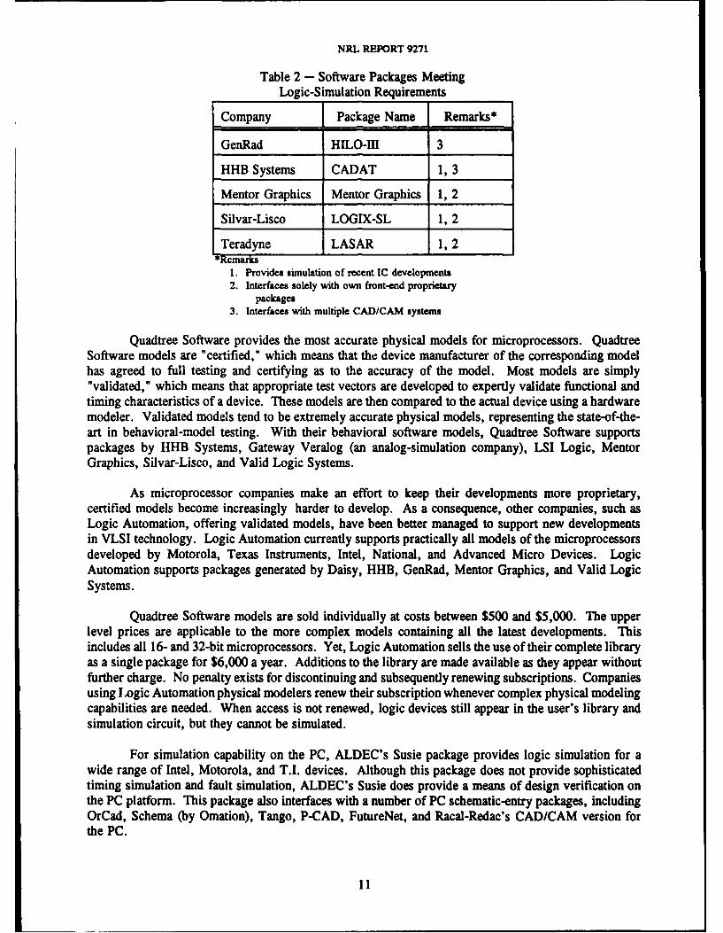
Looking at the cost of the various packages which meet necessary logic-simulation requirements, onlythe HHB CADAT costs less than $200,000; this version is available for about that amount. Only fourof six available simulators meet the requirement cited in this study for support of recent developmentsin IC and, in particular, support VLSI devices. Among these, only CADAT offers the widest range ofplatforms, including Apollo, VAX VMS and ULTRIX, SUN, PC, and HP. Table 2 presents a summaryof information pertaining to these packages.
Physical Modeling Capabilities
Of the six companies offering logic simulation, only HHB and Teradyne offer physical modelingcapabilities directly. The others rely on such physical modeling companies as GenRad, QuadtreeSoftware, and Logic Automation. HI-CHIP, GenRad's physical modeler, sells for $69,200. Tektronix(as previously stated, the CAE Division was recently acquired by Mentor Graphics) and Hewlett-Packardsell HILO-Ill and HI-CHIP as options for their CAD/CAM packages.
10
NRL REPORT 9271
Table 2 - Software Packages MeetingLogic-Simulation Requirements
Company Package Name Remarks*
GenRad HILO-III 3
HHB Systems CADAT 1,3
Mentor Graphics Mentor Graphics 1, 2
Silvar-Lisco LOGIX-SL 1, 2
Teradyne LASAR 1, 2*Remarks
I. Provides simulation of recent IC developments2. Interfaces solely with own front-end proprietary
packages3. Interfaces with multiple CAD/CAM systems
Quadtree Software provides the most accurate physical models for microprocessors. QuadtreeSoftware models are "certified," which means that the device manufacturer of the corresponding modelhas agreed to full testing and certifying as to the accuracy of the model. Most models are simply"validated," which means that appropriate test vectors are developed to expertly validate functional andtiming characteristics of a device. These models are then compared to the actual device using a hardwaremodeler. Validated models tend to be extremely accurate physical models, representing the state-of-the-art in behavioral-model testing. With their behavioral software models, Quadtree Software supportspackages by HHB Systems, Gateway Veralog (an analog-simulation company), LSI Logic, MentorGraphics, Silvar-Lisco, and Valid Logic Systems.
As microprocessor companies make an effort to keep their developments more proprietary,certified models become increasingly harder to develop. As a consequence, other companies, such asLogic Automation, offering validated models, have been better managed to support new developmentsin VLSI technology. Logic Automation currently supports practically all models of the microprocessorsdeveloped by Motorola, Texas Instruments, Intel, National, and Advanced Micro Devices. LogicAutomation supports packages generated by Daisy, HHB, GenRad, Mentor Graphics, and Valid LogicSystems.
Quadtree Software models are sold individually at costs between $500 and $5,000. The upperlevel prices are applicable to the more complex models containing all the latest developments. Thisincludes all 16- and 32-bit microprocessors. Yet, Logic Automation sells the use of their complete libraryas a single package for $6,000 a year. Additions to the library are made available as they appear withoutfurther charge. No penalty exists for discontinuing and subsequently renewing subscriptions. Companiesusing I ogic Automation physical modelers renew their subscription whenever complex physical modelingcapabilities are needed. When access is not renewed, logic devices still appear in the user's library andsimulation circuit, but they cannot be simulated.
For simulation capability on the PC, ALDEC's Susie package provides logic simulation for awide range of Intel, Motorola, and T.I. devices. Although this package does not provide sophisticatedtiming simulation and fault simulation, ALDEC's Susie does provide a means of design verification onthe PC platform. This package also interfaces with a number of PC schematic-entry packages, includingOrCad, Schema (by Omation), Tango, P-CAD, FutureNet, and Racal-Redac's CAD/CAM version forthe PC.
11
LYNN M. KEUTHAN
Printed-Circuit-Board Work Systems
Almost all of the large workstation-based companies meet the primary requirements for a PCBsystem. The larger companies, those meeting at least 80% of all requirements, also provide excellenttools for routing multilayer boards, for creating power and ground planes, and for routing at high speeds.
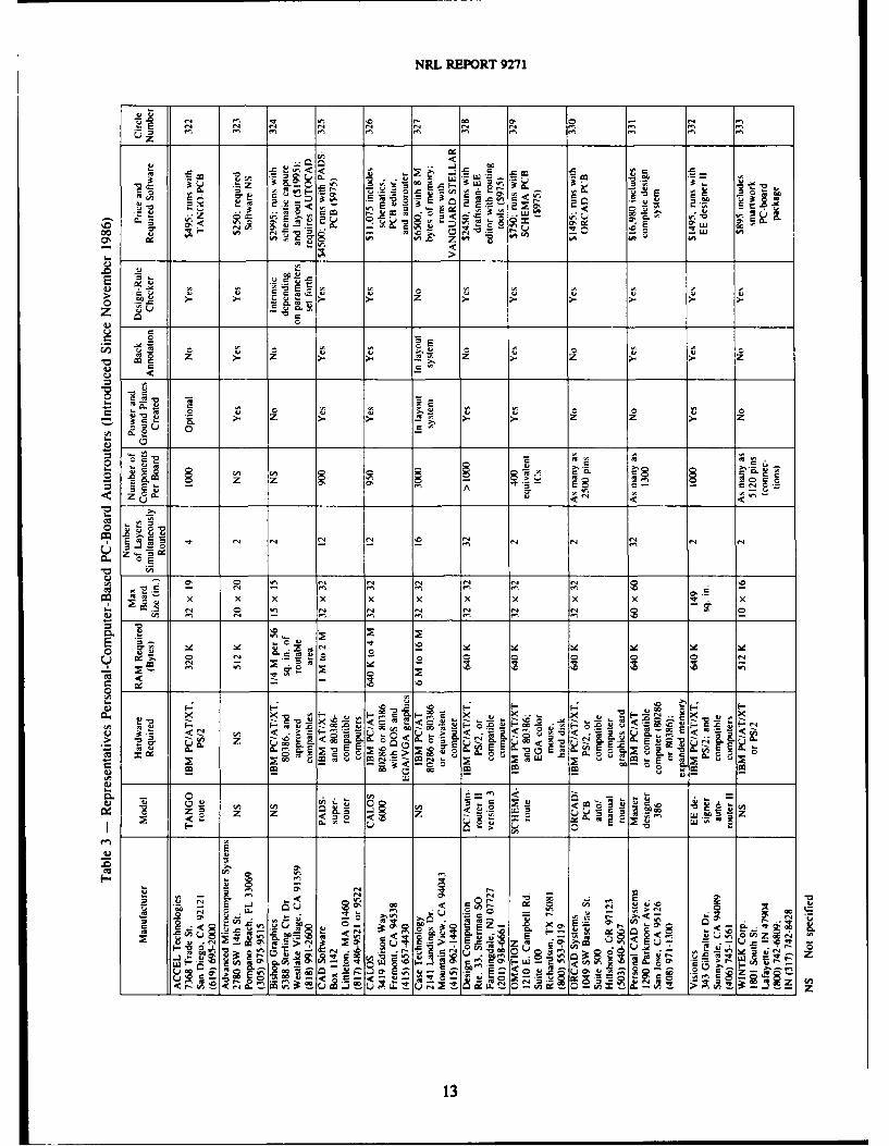
A few PC-based companies are beginning to compete with the powerful autorouting tools foundpreviously only on large workstations. Table 3, reproduced from EDN News of January 1988, lists andcompares PC-based companies that have entered the autorouting arena. Only CAD Software and CALOSroute up to 12 layers simultaneously, create power- and ground-planes, and provide back annotation.These two packages also provide design-rule checkers and route boards up to about 3 x 3 ft withapproximately 1000 components. CAD Software and CALOS are also the only two companies thatprovide rip-up and retry autorouting algorithms. PADS Super-router costs about half the price of theCALOS 6000.
Some PC-based packages, such as OrCad and PCAD, have incorporated many features availablepreviously only on mainframe workstations. These features include surface mount, placement of integatedcircuits (ICs) on top of ICs, and component placement on both sides and use of small outline packages(SOPs). With these packages, the layout engineer can also place copper zones on any layer of any size.Copper zones can be created by using vertical, horizontal, and 450 lines down to 1-mil resolution. MostPC PCB packages include layout error checking for track-to-track, pad-to-track, and pad-to-pad spacing.Most also have more than one routing algorithm, allowing shorter tracks to be placed first and then usinga rip-up and retry strategy to route the remaining signals.
Limitations on the PC still exist because of memory limitations. Claims by PC PCB companiesof routing boards with thousands of components are often misleading. To compare numbers of com-ponents routed by using different PC packages, a baseline must be established. This baseline mustinclude the type of package used (e.g., 14-pin dip) and the total length of tracks placed. The number ofcomponents which can be placed depends upon these factors, which in turn rely on the amount ofmemory addressable by the PCB package.
Another limit caused by the amount of addressable memory is the number of layers which canbe routed simultaneously. OrCad plans to add addressing prefixes to allow their package to accessexpanded or extended memory as a RAMdisk or hard disk. Other PC PCB manufacturers are trying toovercome the handicap of only a small number of libraries being currently available. Many PC CADmanufacturers are making efforts to increase drastically the size of schematic and PCB libraries for theirrespective packages, particularly for leadless chip carrier (LCC) and SOP parts.
STANDARDS
A number of companies intend to adopt new standards being developed. One recently proposedstandard for an operating-system interface has been developed by a group at the Massachusetts Instituteof Technology (MIT). A committee was formed that included representatives from large computer-industry companies. This committee agreed to adopt the X-windows format.
Several of the CAD/CAM companies intend to adopt the X-windows format. Included are Racal-Redac, Silvar-Lisco, and Tektronix. (The latter's decision antedates the aforementioned acquisition byMentor Graphics.) X-windows is intended to become a standard for all workstation operating systems.This standard is being designed to allow a user to move from one platform to another and then pop upan identical window for operating application software. This will provide transparency across thenetwork.
12
NRL REPORT 9271
z
-o< <z E -S
**- .-~- -n c4O 2", .J acr ~ ~ gz 8-E -t _
-Zj u, A 0 U UL 4.
z 'Aa.>
~cE .7.s
E- Z > .
-z z .>. z.
r, CL r So E
C- L
E ru
I- 0 CLA
CA >
om <
*0 0' E__ E_0,0 -0 0' 0. E. m. m. (4 '0
0 . < .
w ,
U c
u- :2-- < < -4;Ca.u - - U
A. - 0 T, a,, a W,02u..
<u ,
_ ~ ~ 6 <. . _- >
_ ~13
LYNN M. KEUTHAN
Racal-Redac has decided to adopt X-windows for their CAE system. They made a furtherdecision to include it with other industry standards such as NFS, a network file-format standard, andStructured Query Language (SQL).
As a company required to interface to many systems with its testing devices, Tektronix hasadopted all of the industry standards, NFS, SQL, and planned to adopt the X-windows standard. Hewle-tt-Packard has adopted the Electronic Design Interface Format (EDIF) for file exchange. The lattercompany may be slow to adopt other standards since, to date, the choice of the company has been aproprietary, closed-architecture system.
It is anticipated that such companies as Computer Vision and Mentor Graphics will make everyeffort to keep their systems closed and proprietary. This probably means that it will be some time beforeindustry standards are more widely adopted, in particular X-windows.
TESTING INTERFACES
The most prevalent testing interface is the one developed by Test System Strategies, Inc. (TSSI).This company was formed as an offshoot of Tektronix. Its founders decided that an industry standardshould exist for interfacing with testing equipment to allow for board testing in completing the design andsimulation of hardware.
Most large companies have adopted the TSSI interface for integration to testing equipment. Thesecompanies include Computer Vision, G.E. Calma, HHB, GenRad, Mentor Graphics, Racal-Redac, Silvar-Lisco, Tektronix, and Teradyne. This provides an interface to Tektronix's powerful Digital AnalysisSystem (DAS 9200). The DAS 9200 provides prototype and limited production-board testing capabilitiesas well as board software debugging and analysis.
DOCUMENTATION
Documentation requirements normally consume a great deal of the engineer's time. They includesuch items as reports, proposals, manuals, and system specifications. In designing digital hardware,documentation can include incremental design annotations for each stage of a design, design annotationsfor possible trouble-shooting, annotations specifying connections to a larger system, and internal designannotations.
Documentation packages that allow an engineer to expediently document design decisions andtheir effects on board design are necessary in a CAE system. The first package to allow a designer toincorporate schematics and text was developed by Interleaf. This has been the standard such package forcomparison for documentation capability. It provides tremendous capability in manipulating text andschematics to yield presentation-quality documentation. This advanced electronic publishing system runson the SUN, Apollo, Apple, Digital, and IBM workstations.
In the interim since Interleaf developed their documentation package, another company, Ventura,has also marketed a comparable documentation package. Ventura was subsequently acquired by theXerox Corporation who now markets the Ventura publication package. These packages offer tremendouscapabilities for integrating schematics, waveforms, and text supplying the additional documentation needsof a design engineer.
14
NRL REPORT 9271
PROPOSED SOLUTIONS
Proposed Solution Number One
The first solution recommended for CAD/CAM development is a PC-based system making useof the OrCad System schematic entry and PCB packages, the HHB CADAT logic simulator, and LogicAutomation physical modelers. The inclusion of HHB CADAT also permits interfacing to the Interleafdocumentation package. The overall system would cost about $32,000. The Interleaf package would costan additional $5,000.
This solution provides the interfaces needed to develop an integrated, turnkey system for CAE.OrCad meets more of the schematic entry requirements than any other package available for operatingon the PC, 89% of such requirements. The solution is one of the most versatile and user-friendlypackages available. OrCad's package is available at $3,080. NRL's Ships EW Branch already hasseveral of OrCad's schematic-entry packages.
To repeat some of the factors that led to this solution: Of the six possible sources of logicsimulation identified as supporting all requirements to some degree, only four of these have kept up withnew IC and VLSI developments. Of this group, only the CADAT package offers more than oneinterface, and a version is available for PC-based systems. The CADAT package, because of itsinterfacing and state-of-the-art logic simulation capabilities, is the most widely used logic simulator at thistime. CADAT is also the only logic simulator providing these capabilities for less than $200,000, asDASH-CADAT PLUS.
Two companies that specialize in physical modeling also interface to CADAT to produce evenmore modeling capability for complex microprocessor devices. These companies are Quadtree Softwareand Logic Automation. The latter is the only source of physical models for the most recent Intel,Motorola, and Texas Instruments microprocessors.
CADAT is one of only two logic simulators that explicitly provide concurrent fault simulation.This feature saves considerable time when testing multiple-serial fault paths.
OrCads PCB package is adequate for boards with up to approximately 200 14-pin dip-typepackages. Copper zones of any size can be created on any layer down to 1-mil resolution manually and5-mil resolution with autorouting. OrCad's package does not back-annotate gate or pin swap. Instead,OrCad allows the designer to recompile a schematic which has already been laid out. Any changes inthe design can be rerouted without affecting routed unchanged connections. OrCad has several routingalgorithms, including a 90 ° strategy, a no-via strategy, a rip-up option, and an optimizer. The rip-upoption reprioritizes routes by accommodating any unrouted signals directly and ripping up any previouslyrouted signals in the path. The optimizer attempts to reduce vias and tracks.
In summary, this PC-based solution will allow quick access to the hardware necessary to supportthe software. It also provides an easy means for transfering files to other PCs. An 80286-based PC witha 130-megabyte hard disk and 16 megabytes of memory is recommended. This configuration meets allnecessary installation requirements and still allows a significant reserve of memory for simulation andCB-design computations, and it allows sufficient storage of design files along with applicable software.
15
LYNN M. KEUTHAN
Proposed Solution Number Two
The second CAD/CAM system solution recommended is that by Racal-Redac and HHB's Visula-CADAT version on a SUN platform. This system costs $189,500 with the inclusion of Interleaf s $5,000documentation package.
Racal-Redac meets 95% of the stated requirements, more than any other system after MentorGraphics' acquisition of the Tektronix CAE division. Not only is this an exceptionally powerfulCAD/CAM system, but it is also well-integrated and user-friendly. The company has developed a broadbase of customers, including many in the military. Two systems are in place at NRL, and the companyservices the Metropolitan Washington area from a Northern Virginia location.
Racal-Redac has already adopted applicable industry-wide standards, including NFS and SQL.It has agreed to the adoption of X-windows. When these standards are used with platforms such as theApollo, VAX and SUN, tremendous flexibility becomes available to manipulate files and interface withadditional equipment.
Through the CADAT interface a designer has a direct connection to testing equipment utilizingthe TSSI format. Also, standard ASCII files are created; this allows a designer an easy access to uploadand download program code used to develop a system.
Configuration control, as used in the military aerospace communities, is a part of the system.This results in design reliability, availability of MIL-SPEC versions of parts, and the addition of controlsto ensure proper documentation.
Through the Interleaf documentation package a designer can easily integrate text with schematics.Accuracy is ensured by denying access for editing a schematic after the documentation package has beenentered. Such editing is restricted to the original schematic rather than a documentation copy.
The benefits of CADAT that have been covered in Solution No. 1 are equally available in thissolution. These also include plans by HHB to enlarge its analog simulation capabilities by using the SUNplatform and Visula-CADAT. Should analog simulation beyond simple components (such as pull-upresistors) be desired in the future, this system would be the best solution. It would then allow concurrentsimulation of analog and digital components on a board or comparisons of "equivalent" analog and digitalcircuitry.
Proposed Solution Number Three
The system described in this solution is what would be offered by Teradyne for about $249,300with the VAXStation 3520 or 3540 workstations. The system would have superb capability for schematicentry, logic simulation, and PCB design. Teradyne's recent acquisition of Case Technology gives theformer access to one of the leading schematic-entry and PCB-design packages. A fully-integratedoperating environment between the schematic-entry package and LASAR has now been effected.
As already noted in some detail, the Case Technology package is extremely user-friendly uidversatile. Placement and routing software is interactive to provide both manual and automatic placementand routing of isolated areas or of an entire board layout, including multilayered boards. Tremendousflexibility exists to define wire widths and pad sizes for soldering.
Not only does Teradyne allow min/typ/max timing, but it will also take into account such circuitproperties as gates that tend to track one another and the common origination of signals. LASAR
16
NRL REPORT 9271
provides detailed hazard reports that completely describe any possible design problem and suggest thelikely causes of the hazard. With the use of Teradyne's hazard reports, a designer has greater flexibilityin logic simulation to determine the sources of glitches and to decide whether they will affect the actualboard operation. Serial and concurrent fault-simulation capabilities are provided along with test-patterngeneration for board verification.
Teradyne's recent acquisition of AIDA added more board-testing capability. From this moveintegretion of logic simulation and board testing has developed. This integration has made it possible toinput additional information to the board-testing equipment to test for current loading and power-sourcearcing.
Running on the VAX platform provides a standard and familiar operating-system environment.This also provides more powerful operating system tools and easy transfer of files from other VAXsystems, including those based on mainframes. When compared to using the PC platform, the use of thisplatform greatly reduces running time. Comparisons of compute time for running Teradyne's LASARon the SUN vs running on the VAX, show the VAX VUP (VAX unit of performance) as having morecomputational power than the SUN MIP (millions of instructions per second) for this particularapplication software.
The Teradyne system can be purchased for $249,300. This price includes hardware modelingfor the Intel 20826, Motorola 68000 and 68020, and Texas Instrument TMS32020 and TMS320C25. Itappears to be more efficient and less costly for NRL to purchase the VAXStation from Teradyne thanfrom Digital Equipment Corporation under the GSA Schedule. This would allow acquiring the Teradynesystem for $180,300. $83,800 of this would be for schematic design, logic, and fault simulation, plusthe PCB layout with design-rule checker. The remaining $96,500 would cover the cost of the hardwaremodeling subsystem.
In an environment heavily geared toward production, many board-design problems may goundiscovered until manufacturing is completed and mass production has begun. The Teradyne systemwould preclude most of these problems and save countless manhours of work. This solution offers themost comprehensive set of logic- and fault-simulation capabilities while providing flexibility in a CAEsystem. In such an environment or one where design reliability is critical, this system would be thenumber-one recommended system.
PRICE/PERFORMANCE FOR THREE PROPOSED SYSTEM SOLUTIONS
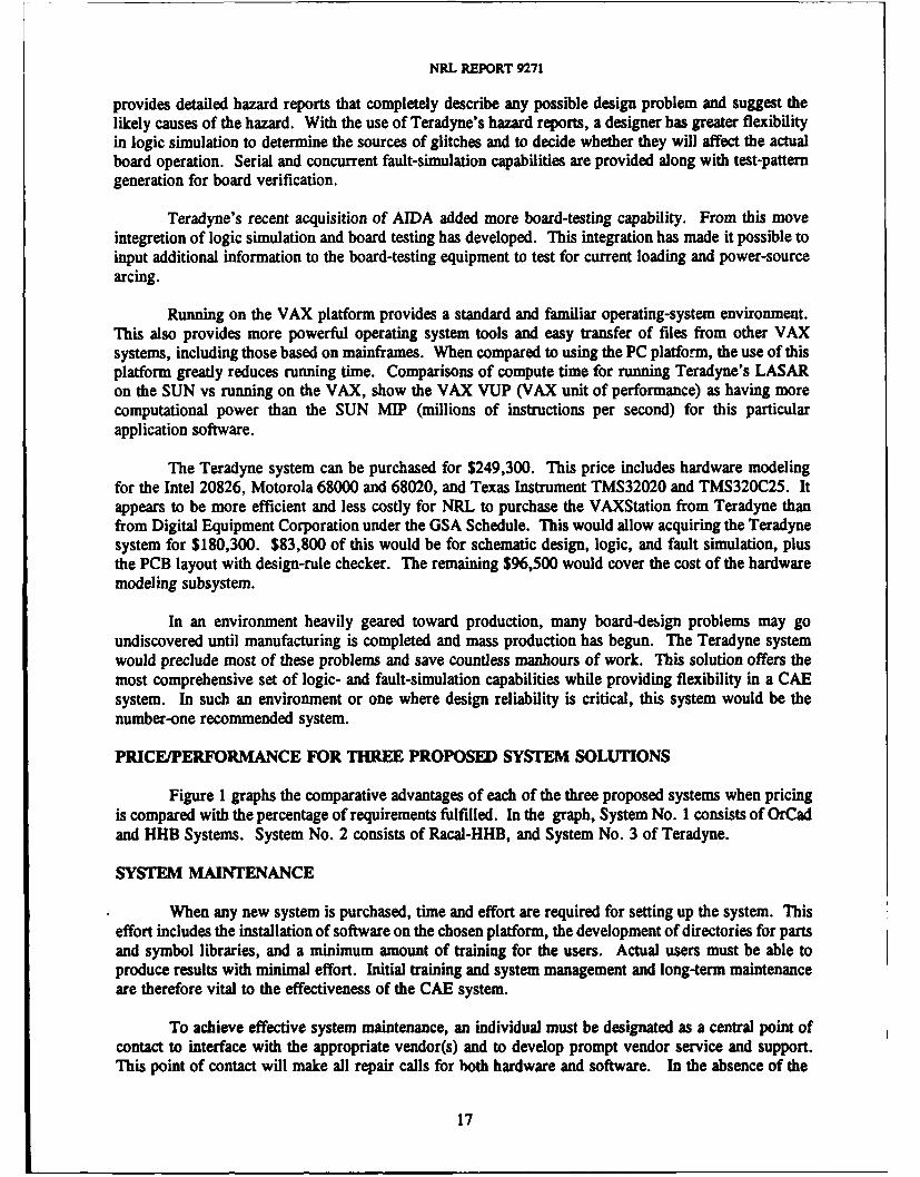
Figure 1 graphs the comparative advantages of each of the three proposed systems when pricingis compared with the percentage of requirements fulfilled. In the graph, System No. I consists of OrCadand HHB Systems. System No. 2 consists of Racal-HHB, and System No. 3 of Teradyne.
SYSTEM MAINTENANCE
When any new system is purchased, time and effort are required for setting up the system. Thiseffort includes the installation of software on the chosen platform, the development of directories for partsand symbol libraries, and a minimum amount of training for the users. Actual users must be able toproduce results with minimal effort. Initial training and system management and long-term maintenanceare therefore vital to the effectiveness of the CAE system.
To achieve effective system maintenance, an individual must be designated as a central point ofcontact to interface with the appropriate vendor(s) and to develop prompt vendor service and support.This point of contact will make all repair calls for both hardware and software. In the absence of the
17
LYNN M. KEUTHAN
COMPARISON OF THREE SYSTEM SOLUTIONS
200 iTflu$RftD
180160
Z 140 syxs 3*s's2
120
1 100
80
40. SYS120j
088 90 iYS i9 800
PERCENTAGE OF~ REQUIREMENTS
*System No. 3 has added simulation and testing capabilities beyond requirements.
Fig. 1 - Graph of comparative system advantages
primary point of contact, one or two alternates should be named to place service calls. This arrangement
will assure the proper functioning of the CAD/CAM system and its maximum use and benefits.
RESULTS OF EVALUATION OF TERADYNE'S CAD/CAM SYSTEM
Background
In the period of 5 to 7 June, 1989, Code 5740 at NRL conducted an evaluation of Teradyne'sElectrical CAD/CAM System. This was made possible by that company by loaning a system for theevaluation. Appropriate engineering support was also provided.
After this brief period at NRL, Teradyne continued the work at their headquarters. This phaseof support addressed areas that, because of lack of enough time, could not be appropriately evaluated inthe NRL phase.
Goals of the Evaluation
To evaluate the Teradyne system, a set of goals was compiled:
*Follow the simulation process through step-by-step. (Examine accuracy and ease-of-use.)
*Intuitively analyze LASAR's process of integrating program code, memory, andprogrammable logic into the simulation process.
*Test the input of the CASE netlist generated by OrCad.
*Compare the PCB layout and routing between PadsPCB and CASE for a simple circuit.
18
NRL REPORT 9271
" Test both layout and routing for a complex multilayer board.
* Examine LASAR's ties to analog simulators (in particular to Analog Design Tool's simulator)and examine the front-end simulation of DACs.
" Analyze LASAR' capability as a tool for accomplishing reverse engineering.
These evaluation goals were also made available to Teradyne so that they could demonstrate theability of their system in accomplishing these goals. The successful accomplishment of the goals was thecriterion for determining whether the Teradyne system met the CAD/CAM requirements of NRL Code5740.
DETAILED DISCUSSION OF GOALS
Goal Number One
This goal was designed to determine how much time is required for a relative novice designerto learn Teradyne's CAD/CAM system and determine whether such a person might learn the system onhis/her own. Two approaches were taken.
In the first approach, a Teradyne applications engineer stepped through the design and simulationprocess with a schematic supplied by NRL. During this process, NRL personnel received hands-onpractice with the system. After about four hours, the flow of the design process, the most commonlyused commands, and the system menu started to become familiar to the participants. It became evidentthat a designer could successfully bring up the system and take a design through schematic entry, theelectrical design rules checker, simulation, and PCB layout with minimal reference to the manuals. Itwas also found that Teradyne's menu supplied one- and two-keystroke easily executed commands. It waslearned that the interface was identical regardless of whether the user was entering a schematic, runningthrough a simulation, or creating a PCB layout.
For the second approach, a second copy of the system was loaded on a personal computer toallow a designer unfamiliar with the system to learn with only the manuals as a guide. The manuals wereeasy to follow. They contained tutorials for each procedure. The particular designer participating in thisactivity was a student summer employee who spent about one week in learning the system completely.The student also spent time learning OrCad. Both the OrCad and CASE systems were easy to use; thelatter required more time because it provides more capability than the former.
Goal Number Two
This goal was designed to "see" the Teradyne system in action, dynamically changing simulationresults with input-circuit changes. The objective was to verify that the system would accomplish theclaims of the promotional literature and that simulation results would .igree with the actual hardwareresults.
For this procedure, NRL provided a schematic of an 80286 circuit containing 59 ICs and 89components. The schematic was taken from a board that had already been wire-wrapped and tested. Theboard contained 64K of ROM and 16K of RAM; it also contained 3 PALs. NRL provided code for aprogram initializing a counter/timer and USART. It then outputs a message to a monitor through RS232and allows commands to be input to examine or modify memory, input and output to ports, examineregisters, set breakpoints, and execute code.
19
LYNN M. KEUTHAN
This schematic was entered into the CASE VANGUARD portion of the system; it occupied threeE-size drawings. A library symbol was created for Intel's 82389 chip, a 149-pin PGA device. Thesimulator imports PAL code by using PALGEN or Circuit Maker, with JEDEC files supplied. (CircuitMaker packages the fuse-map files into PAL models.)
A Teradyne engineer wrote a program to automatically load the NRL PAL files that had beencreated by using PALASM. For the ROM model, Teradyne's LASAR simulator accepts Intel HEX code.The schematic was compiled. The process of compilation identified problems in the circuit entry. Aftermaking corrections and recompiling, the simulation process was started.
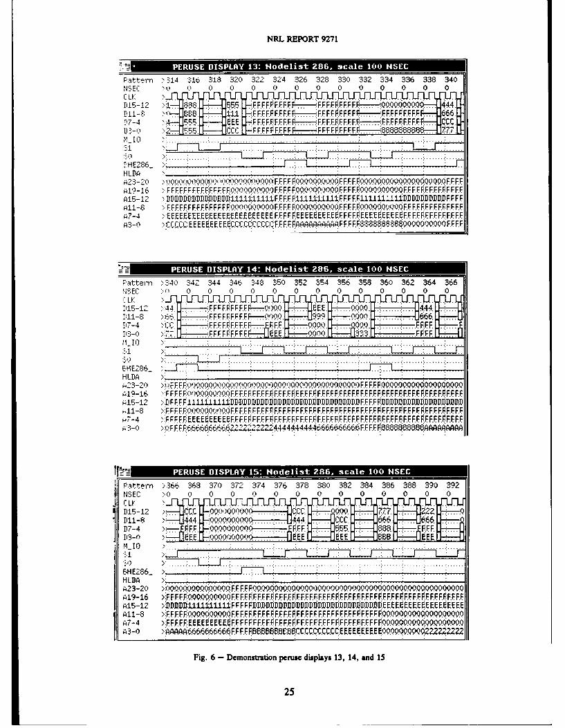
The first simulation run produced an overflow error in the ROM model. A block of code filledwith Fs after the program code overflowed past the 80286 start address, FFFFO, where the 80286automatically initializes. The block of Fs was removed from the simulation code, and the 80286 startaddress was forced to FFFFO. The simulation was then rerun with the 80286 finding the initial jumpinstruction at FFFFO. This proved that the PAL model was functioning correctly and had been loadedcorrectly with the engineer's program. However, the 80286 did not jump to the correct program code.Apparently, the ROM model was not functioning correctly.
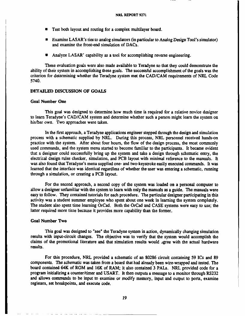
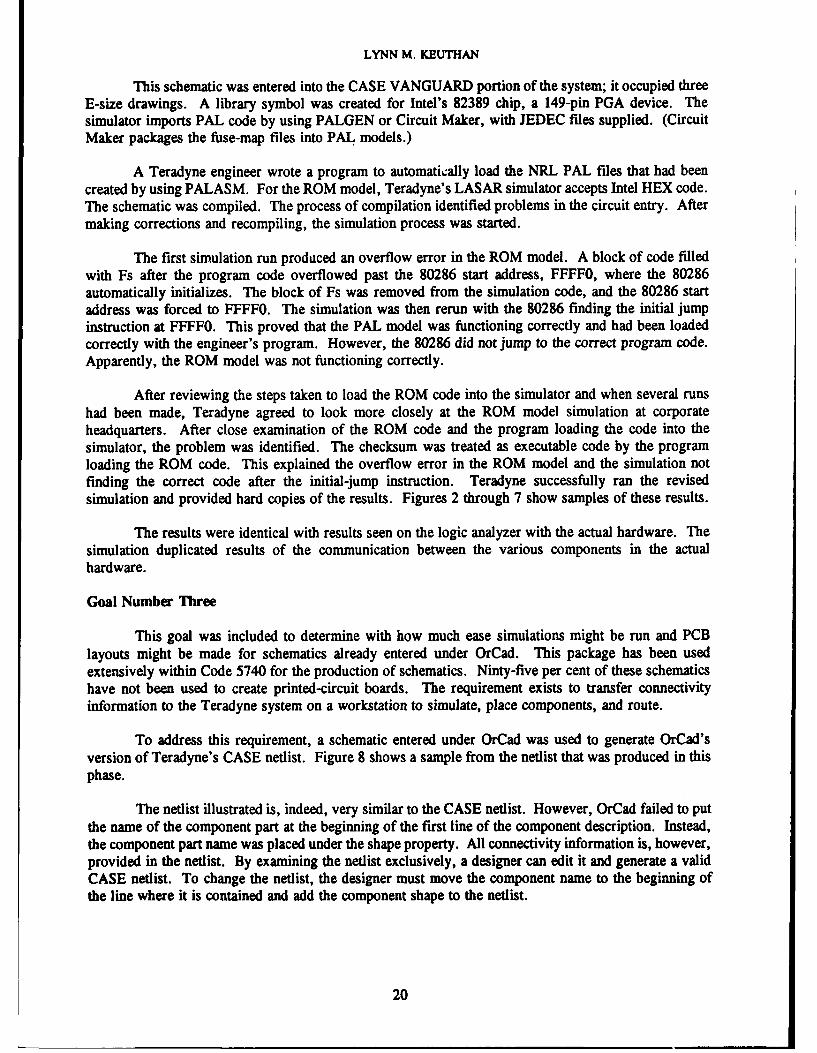
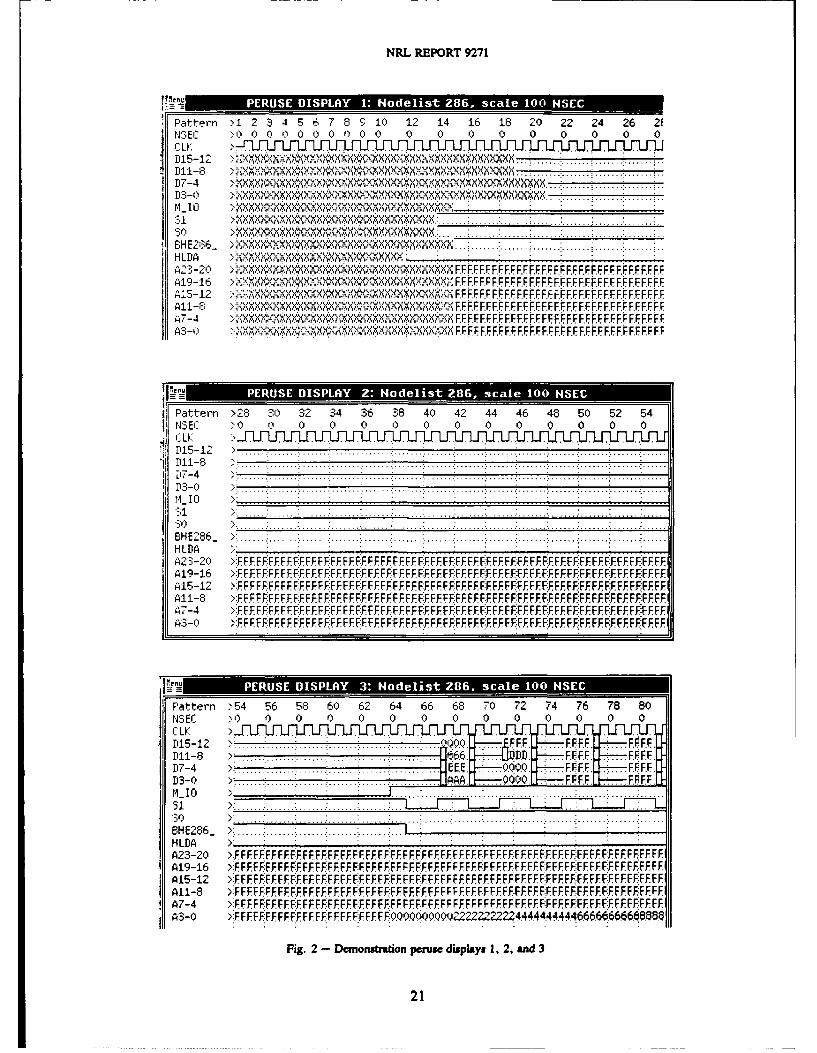
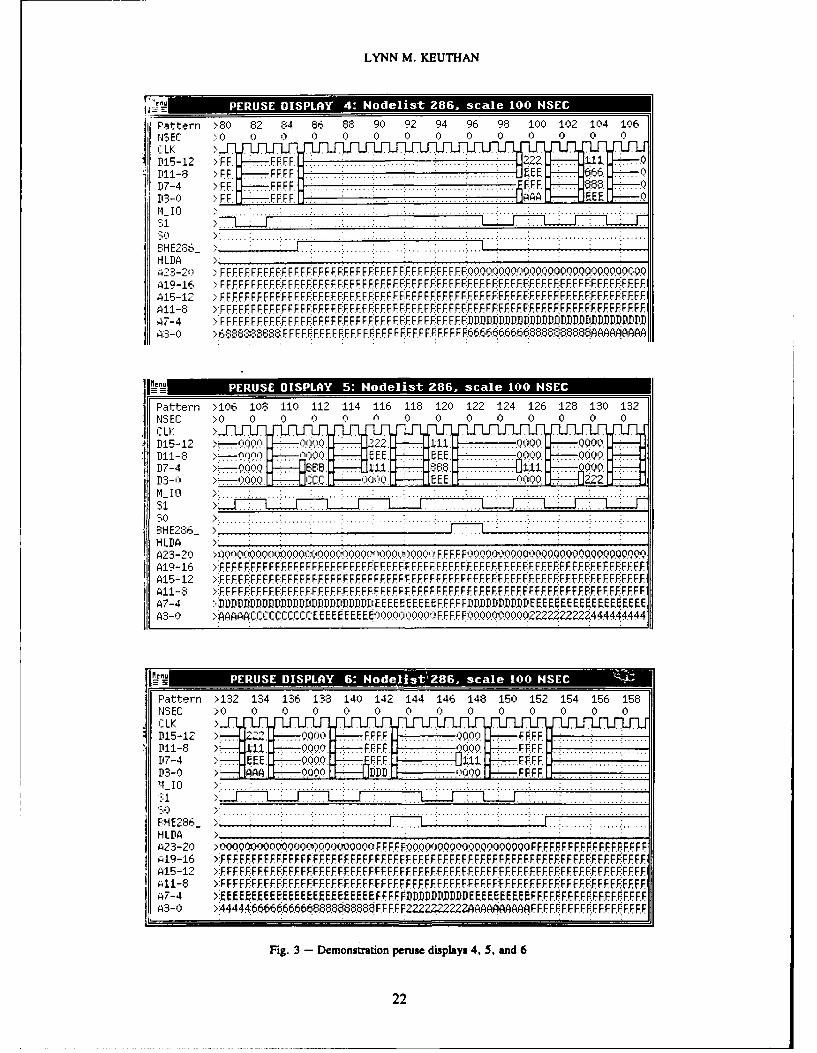
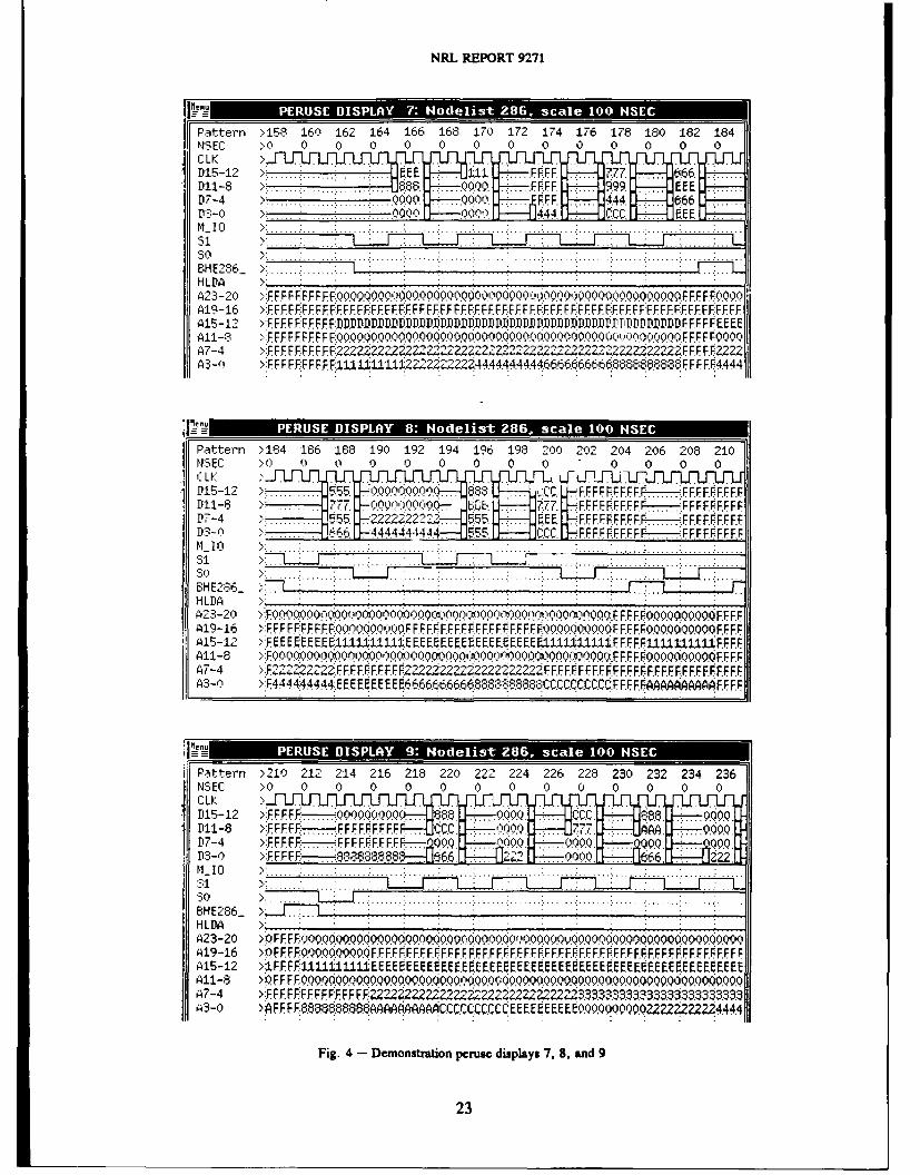
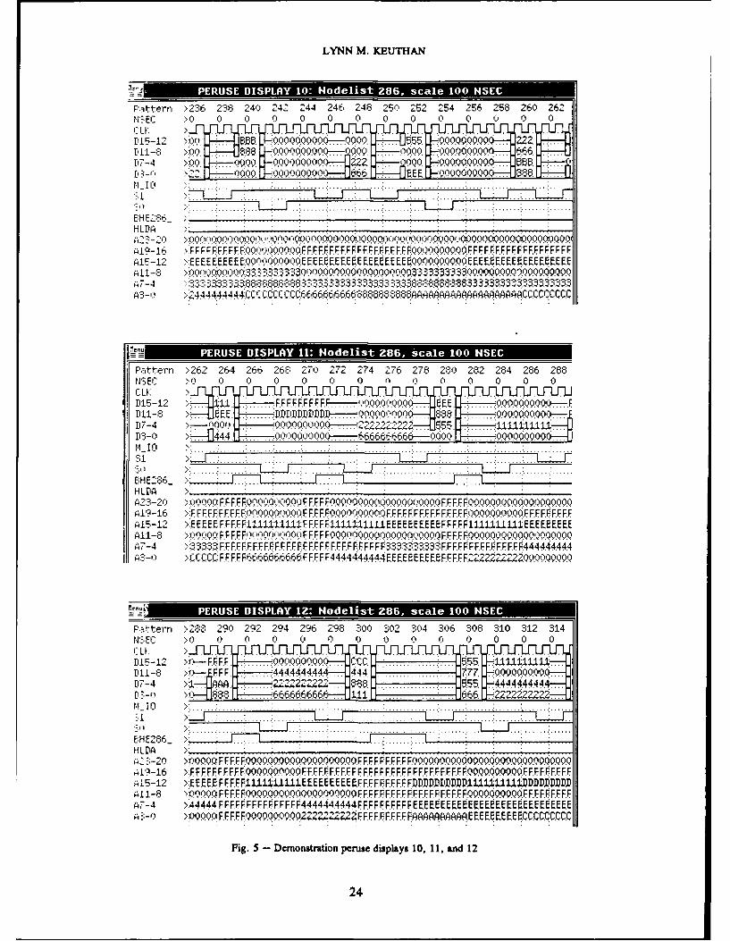
After reviewing the steps taken to load the ROM code into the simulator and when several runshad been made, Teradyne agreed to look more closely at the ROM model simulation at corporateheadquarters. After close examination of the ROM code and the program loading the code into thesimulator, the problem was identified. The checksum was treated as executable code by the programloading the ROM code. This explained the overflow error in the ROM model and the simulation notfinding the correct code after the initial-jump instruction. Teradyne successfully ran the revisedsimulation and provided hard copies of the results. Figures 2 through 7 show samples of these results.
The results were identical with results seen on the logic analyzer with the actual hardware. Thesimulation duplicated results of the communication between the various components in the actualhardware.
Goal Number Three
This goal was included to determine with how much ease simulations might be run and PCBlayouts might be made for schematics already entered under OrCad. This package has been usedextensively within Code 5740 for the production of schematics. Ninty-five per cent of these schematicshave not been used to create printed-circuit boards. The requirement exists to transfer connectivityinformation to the Teradyne system on a workstation to simulate, place components, and route.
To address this requirement, a schematic entered under OrCad was used to generate OrCad'sversion of Teradyne's CASE netlist. Figure 8 shows a sample from the netlist that was produced in thisphase.
The netlist illustrated is, indeed, very similar to the CASE netlist. However, OrCad failed to putthe name of the component part at the beginning of the first line of the component description. Instead,the component part name was placed under the shape property. All connectivity information is, however,provided in the netlist. By examining the netlist exclusively, a designer can edit it and generate a validCASE netlist. To change the netlist, the designer must move the component name to the beginning ofthe line where it is contained and add the component shape to the netlist.
20
NRL REPORT 9271
7TenL aa
Fattern >1 2 3 4 5 6 7 8 10 12 14 16 18 20 22 24 26 2ENSEC >0 000000000 0 0 0 0 0 0 0 0
D 1 1 -8 >.......... . ... ... . .
D. . . . ..............
:'1 X, ., +',' X X,'.X: :X X X X :.. ...; ....... ....... ....... ....... :....... :....... .
BH E 28 ; ....... .......... .............. .HLDA ' . .M
A2:',-20 .X",m M~~~ -," FFF.FFFF.FFFFFFFF.FFFFFF.FFFFFFFFFE.A19-16 ...... ., < x.xx., x,, , F F FE F FE FE F F F. F F.FA-12 ." XXXXXX'X FF FF.EF.FF.FFFF.F.FF.FF.FF.FFFF.FAHI-8 . .,F F.F r FF F F F.F EF..F FF PF F F FE FF F
A.7- F.FFFF.FFFF. F FF.F FF. F.F.F.F.F .FF. FF.F FF
1110Pattern >28 30 32 34 36 38 40 42 44 46 48 50 52 541:3 EC > 0 0 0 0 0 0 0 0 0 0O 0 0 0
Z 1 -1 7 .. .. .4 ......... .. ............................. ............................... ......................ij7-4 "
D 3 - 0 ........................ ....... ...................................... F.....................................
A] > : ..... : . . . .:.. . . .:. . . ." . . . .:. . ..: . . ... .. ..: .... .. : ..... .. " . ...: ..... : .. ..... .:. . .
B H E 2 8 6 _ > : ........ ......... ........ ....... ........ ....... ........ ....... ........ . ..... ....... ....... ....... .....HLDA
A23-20 :':F FFFFFF F F FEE F FF. F F FF.FF FF. FFE. F FF:EFE FF F F: FEF FEFE FE FFF FEA19-16 ":F FF,.FFF F.P FF.F. FFF. FF. FF. FFF F FF. F:F FF. FFFF. FF. F. F F-:FF FF. FF. FF. FF FF. FF. FF. FFF FF.
A15-12 >.-FFF FF FF.FFEFEFF F FF. FF FFF FF. F. F E FEF FE FF. F FF. F FE F FE:FF. FE FFF FEZI1-8 >F FF FEEF FF. F. FF.FFE FF. FF FF. FEFE FE. F F F FF. FF FF. FF.F FE FF.EFEEFE F:E FFFP:FE FE
E74 -FF.FE:FF.FF.F:.FE FE.F FFFEFFEFE.FF.EE .F.EEFE FEF FE EEEEFE FE F:EFEEFEFEg3-0l >.F FFFEFFFFE. FEFFE FE FE FEFE F.FE FEFEFEFE FEFFEEFE.E F:EE .E FE FE E E FEFEF.
Pattern >54 56 58 60 62 64 66 68 70 72 74 76 78 80NSEC >0 0 0 0 0 0 0 0 0 0 0 0 0 0
Cii -8 >,[-. , .. .,. .F FF ., .. .... .
M 55- 1 2 >:............... ...... : .......:....... .......:... .A. + ..F .FF .. FF .F.
D1 -8 > ...... EFF........E ........ F............. .... E..ED 7 -4 > :.. .. ......... . ...... .. . .. .. : .. ... .. ...:....... : F F ..... .. ..
H L1 y ... ....... . .......
AT- >:F FEFE:E E . .EFEFF FEF:.E E F FFFFF .F.FE EFFE FE.F FEFEFE:E FE:EE E:FEFE,H2 6 : . .. ... . . .. . , .. . . . . . . . . . . ..... . ,
A,3-0 >F FE FFE FE F F FE FE F FE. FF-'Q'F.Q9QQQ0Q2222'2-,222.444444444666F666666.68.86I
Fig. 2 - Demonstraton peruse displays 1, 2, and 3
21
LYNN M. KEUTHAN
'ernu *I1J32MIMI MErv RTMJPattern >80 8, 2 84 86 88 90 92 94 96 98 100 102 104 106
11SEC ' 3 0 0 0 0 0 0
D,15-12 >.FF. .... ......FF...... :....... .... 222rn-s ...F FFFF ....... 6..0
D7-4 >FF. FF.. FF ........................... FF 68
HLDe
A19-16 >FFFFFFFFFFFFFFFFFFFFFFFFFFFFFFFPFFFF
A7-4 >:FFFFF:FFFFFFFFFF FFFFFFFF4FFFFFFFFFFFFFFFDD.DDIUPUUDDWDD MD PlDIA3 >S-QR6 U F F FFF F F F F F F F F F F F. F F..F F F F F .FFF EF F ,6 E-E0a-
I1vn* PEUS DISPA 5' H ei. .. .. 28,scl 00
Pattern >106 108 110 112 114 116 118 120 122 124 126 128 130 132.NSEC >0 0 0 0 0 0 0 0 0 0 0 0 0
CLKD 15-12 N7 I~ ........ ..... 111 000 000
P7-4 .-..0 .E 1 6 4 0
8HUO' > . ! -1
A23-20 >)lfQflQ0W f0 ylf -,QflflQflllOi)li F FF F F090090000000.009At141 >FFFFF:FFFfFFFFFF FFFFFFFFFF FFFFFF FFFFFFFFFF.FFFFFFFFFFFFFFFFFFFFFEFF
A:-- > 4 AAA CUCC CQCCC E. EBEEEOQt FFFF'v0f022222 22221444 44444
JPattern >132 134 136 138 140 142 144 146 148 150 152 154 156 158U-SEC >0 0 0 0 01 0 0 0 0 0 0 0
D15-12 >. QOQ Z2..000 FF F.F.00 .... F
HE0 ~ . -. 09M0. F.U FF .00 FF F .........
D3-0 >OQQ0000c)OQ00 FA F F F.. F00000000.00 F FFF .... FFFF .... FF.FF19-1 >FFFFFFF ..................FFF...FF....F...FF.........FFF....F...FF F F FF F F F :F F EF .F ...F .
>4-1 >FFFFFFFFFFFFFFFFFFFFFFFFFFFFFF.FF..F......
A1j-12 >FFFFFF.FFFFF.FFFFFFFFFFFFFFFFFFFFFFF.F.FFFFF.FFF.FF.FFFFFFFFFF.FFFFFF.FF.FFFF.074 >EE EEEE~EE~EEFFFFFPnDPDDPEEBEEEFFFFF5F.F.FFFFFFF.-FFFF.FFFFF.F.FFFF.:F.FFF.-FFF..FF..FF.
A3-0 >44444 6666666666666666 .8?8.F.F F F 222n2222222j'AAAF F.F F.FFFFFF F FF F FF.F
Fig. 3 - Demonstration peruse displays 4, 5, and 6
22
NRL REPORT 9271
Pattern >158 160 162 164 166 168 170 172 174 176 178 180 182 184NS0 0 0 0 0 0CLK
A111
15 -12 > . . . 11 . FFFF ....
11- > . ................. ... ..00.FF.FF . . ...D7-4 > 000 10 .FF 4.4 666
D3-) . 0.. 000 00. 4.44. CC -4EE
Sl >: ........ ....... :.... : - - .. - . .. - .:. . .:. .... .._
S O E 6 > ' : ........ ............... .....:. .. ! ....... . .... .... ....... :. ......; ...
H L DA > . ..; ." .. .. . .. iA23-20 >:E E F F FiF 0FE F 00Q0.0 .0.N)OO F F FF 0 OA19-16 >E FEF:FF F FF F FF. FF.FF. FF. F FFF F. FFFF F. F:FF F. FF.F FFFF.FF F FF FF F U FFF F. FF.F FA15-12 > F FFFF.FU.DP.DDfDPDPDD DP DU flPPPDD flPDDDR.F F.F F.F EE EEA11-8 >.F FF FEFE FF F-QQ 090. .O.Q.0 .. fl.l .j.Q.Q F.F F0000A7-4 >:. F. FE FEFF F F F.22 Z2Z222 Z2?2.22-9 222 2222 22222 12 2. F F F F FZA3-Ol >:F FI F FiFE FiE F4UUUI1;UI Z2~Z222Z44444444446666666666.6666.?868FF F F. 4.
Pattern >184 186 188 190 192 194 196 198 200 202 204 206 208 2100:EC > 0 0 0 0 0 0 0 0 0 0
:L ..-.. .U...... . . .F-......D15-12 > . .0.QOQ l 0 88 ,:. FF F: F F FFF F.F .. FFFFFF.IPl. 7. >N0X .-E, ?.77.. F.FFF.FF.FFF. FF.FF.r F.FFF.FP-4 5 5 5FFFF?2FFF .:.5.F.FFFP.FFF . .FFFFFFFD3-0 ........... . 6 4444444444. 555 .CC. F F F.F F FF. .FF F FF FF.I~l I ,..'... ... ....... ......: ....... ....... ...........: :
...1................... ..' o> : ........: ........ .L ,- ..:.. .. .... ..... ... .. ... .. .... ... ... . L. ....BHE286_ -. -----
I 5-12 !FEE EE E EE E51UtlJ11szE EE EEEE E EEE EE E E1,1, 1J .F FF FFIJ±111 U F. F.FAli- 8 Fflf.flf000r n)(00o:)00o.ooo}o00 (:n)000 Qa)00 .(F. F.F FF.00QQ.a00.0.9F EFA7-4 2NFZZ2.FF.F F. FF FFFF222Z22222222.ZFFFF.FFFF FFFFFFFFFFFFFFFFF
A3-0 >:F44 444444 EE EEEEE EE E6666666?6666. 68888CC.CC.CCCC.F EF F F F fFF
ii Pattern >210 212 214 216 218 220 222 224 226 228 230 232 234 236N$EC >0 0 0 0 0 0 00 0 0 0 0
CLLP115-12 > *FF F F F..0 0 0000 .FFF0Q FCCC Q..0.P1-S >!F. ! FFF.FFF ......,......8.88066P7-4 >F FFF F F FFF FFFFFH-r 0 fOQ 9...90 . 00P3-0) >FFFE .66 866 6A000. . 6.. 2m_ Io > : .....:. ...:. ..: : : : : ........ :.. ..... i.. .....: ....... :: ........ ... .. i.. ...... : ..............:.. ....
o> .......". .... ..................................i .......i. .....i .......i. .......:. .....................BH E286_ > . - T -71 ..; .HLDA X; ;
A23-20 >VF.FF-f'.: .0Q .0000000. 0.0 0090WWI) 090'v.Q.00090.0)0.. QA19-16 >:F FE E . F. F FF. F.F F.F F. F .F.F F FF. FF .F F.F.F F.FF. FF.FF.F ..FF.F. FF.F F.
A11-8 > [F:QQ.QQ Q.QQQQ9QQQQ QQQQ ppQQ Q9
id7-04 B0 EiFFi ~ 22 222 22222233.033.0900.9.23Z22.Z2Z24.44
Fig. 4 - Demonstration peruse displays 7, 8, and 9
23
LYNN M. KEUTHAN
Patt-ern >236 238 '40 24' 244 246 248 250 252 254 256 258 260 262NBE' > 0 0 0 0 0 0 0 0 0 0 0 0
11512 >.ijOQoQO 55, 000050-00 *iQQQ..22Z
P 4 >;0 'O0'-.- 00000( 222 . 00 90.0065117- 96 I.?i)X
4
EH E28rH L ' fD lfI fAO~lrvfQi ~O%000.(~0Q0000000tOOU00)0
A9l 2 2 0 Flp)00OFFFOFFFFKFFF0Q0QQ9FFFFFFFFFFF
EU.. lil
Il~eni .. .........
NSEC4 -0 0 0 0Q 0 0 0 0 9 00 0 0
1ff~~~~...... 1 ......... T11...FFFFF.-f'A00 E....00000in ~ >... SE . fl~PULDD D-----0o~oo ............ .. . :.0.Q0.0---SH'8 -r 1.771. 0f9'(00 k--222222 55
A1Q1 lb 99 FFFFFFQOoOFFO000fuFFFFFFF.FF.FFFF00FFFFF ! O FFF FFH15-12 >.EESEEFFIFF11UtLU±FFF1.FIFIIUUXIII11EEEEEEEEF.FFFIlLUIUUIElEEEEEEEE
u11 9 )00QF FF Fc't.t FF000''i00%®tQF . 000000.000A7-4 ;&33,tFF FF FFF F.FF FF FF FF FF FFFF FFFFF3 FFR FR . .FF4444.I HQ-'. .CFFFFF666-! i6FFFFF444444.444EEEEEE.EEBFFFFF22P Z000
Paittern >288 290 292 294 296 298 300 302 0' 0 308 310 312 314N'3-EC 0l 0 Q 0 0 0 0 0 0 0
115-12 > '-F.FF.F. . .........0.5.0:1 1 I..P111-8 >9- FF.F .. .444444444 . 444.7 ....
P7-4 >1, ~ .. 22222 .. . 66 ................ .55 .- 44444 44
P3-0 t 66 6666666e 1.1 .,. . . . ........ ... ..
E:H E286.
A1916 >IF09 FF FFF. FFOOO00000000R000000.OOFF FFFFFFFF FFFFFF FFFO.00.OFF FFF FF
A7-4 > 44444:FF FPFFF FFFFFF44444444,4 FFFFFF F F EEE EEEEE EE9EEEE EEE EEEE ES-u>1000 FEF EF FQ0.0.0.000 2Zr4 2222ZF F F F F FF FEF FAAAAAAAE SE SE SE EEC QQ.C
Fig. 5 - Demonstration peruse displays 10, 11, and 12
24
NRL REPORT 9271
P.ttern '314 316 318 320 322 324 326 323 330 332 334 336 338 340;NSEC > Q 0) 0 0 0 0 0 0 0 0 0 0
,-..
jJ J -1'15-12 55..66 . 555 FF FFEFfF......F.FFFFFFFFF--.9®0.00Q00. 444.rn- >i'.. 68 . i FFFFFFF FF .F... FFFFF..FF-. FFFFF-..66.6.
',_ ; 55 ;=.F .F.FFFFFFFFFFFFF... ... F F6-- "7.7
H L1 D A .. .. ." - .. .. . .. .. .. .. .. ........ . : . .. .. .. .. ...,. ..... . ...... ...... .. .,.. . .. .. .. . .... ........ . .. . ... . . . . ... . F .F , Q , : . ... . . .. . . . . . ... . .. . ... . . . . . . . . . . .
ELH E2%&H2- - - Of ,,OQO', [ ,r"r 'y'OQn r"OO!.FE F FrOc FOOQOb0F F F FFQOQOQOQQ OOOQ.QQOO FFF F
419-16 .F FF FFFF EE .FF.E E:OO.,00OQF.FFF0QQOQO.lOE.F.EFFO~QO.QOO.O9F.FF E F.FFFEFF.415-12 Phf D lD fOI tIP~~lU 1tU F.E F. F F1~tUUUULE F.F FF£%tI lUPLDfDDPD F.F F.F41I-6 E:FFFF:FEFEFFFE FOOOq Q~QO FFFQQ~QO0000FFFFOOQQ.QQ.QFEFFFFFFFFFFF
A7-4 >:EE.EE.EEEEEEE.EE.EEEEEE.EEEE EF.F.FF.EE.EEEEEEEEFF.F.E.EEEEEEEE.EF.:F.F-.F.F.F.FF.F...-', >f CCEE EE EEEE ECCCCC 'CCC': FEFFFFlMu-3A4PRF F FFF6666?666?69000000000OFFFF
I. . m u - -• 2.. . . . . . . .. . . . I I . .
Pattern :340 342 344 346 348 350 352 354 356 358 360 362 364 366NS EC Q. 0 0 0 0 0 0 0 0 0 0 0 0 0
il- K >J.7 . 666f7-4 ;- 4.....EF.F.F... ..90....... .. F. 4- ,. ..... . . .. .. . . . .115 2 4: . ............FFFFFFFF Q Q ...... ... : 0.. .: . . .. . . 6.. " . . ..D7-4 ........: .. : ... .. .. ... : ... .... .. EFEF.11 10o. aUOFM',- 1'0 .. . . . ... L . .... ..... .- ....... " ...... :....... ....... ... ...... ....... :........ i....... : ........ i ......
6HE'c86_ - . .HLDA ):: :
2-2,') ,"i FE E. 0E,)qOQ20,:Q.,,QQ.,OQQQ,QOQQQ.:QQQ.0.QQQ. E F.E RO.QQQQQO.Q0.QQQQQ.QA19-16 I FFFFg.O.OOQ FFFFFFFFFFF.FFF.F.FFFFFFFF.FFFFFF.F.FF.FFFF.F.F.FF.FF,'FEFFF.F
11- >A FFFEOQQQOOQIJF.FF.F.FFFFFFFEF.EFFF.F.F.EF.EEFFEEFFFEFFEEFF.EEF.EE
, "FEFE.66666666. 2 22444444444.46666.6666.F FE F688. 66 .66 $.RAAAA
Pattern >:366 368 370 372 374 376 378 380 382 384 386 388 390 392ItJ3EC ,0 0 0 0 0 0 0 0 0 0 0 0 0
* t'15-12 :OQ............ QU O fq!Q. 77 7. ?, ZZZ.111-8 >- U.Q 0........ r4.... 444. CU :666 ... 66.
3 >: . "...... . ...... ........ ....... ....... R.HL7]4 SEE. ' :"O" '0. .... .. EE SEE ,. E.........E.
HLDA >A23-20 >..0M .90000000 FE F F. QOQ..O.O..009Q.0000 0 .. QQQQ QQQ. .QQ.09000Q0.QA19-16 >FFE..Q.0Q.OrQQFEFF.FFF FEFE FF FFFF FfF.FFFFFFFF.FF F FFFEF.FFEHFE FA15-12 D.DDI Ut1Ut1FFFFFPDDIWDDD.PPD.DDPDDPDPDDPEEEEEEEEEEEEEEEE411-8 >FFFEOQO.OQQQQQQFFFEFFF FFFFFFFEFF.F.FFFFFFFFFFFQ.00.QQQ.0..QQQ0
A7-4 >FFEFFE.EEEEEEEFFFFFFFFEFFFFFEFEFFFFFFF FF.FFFFQQFF..9.QQ.Q.QQ.Q.0..A3-0 >AAA6666666666EFFEFBB8E8EEECCCCCCC.CCEEEEEEEEO.0009.QQ.Q0222222222
Fig. 6 - Demonstration peruse displays 13, 14, and 15
25
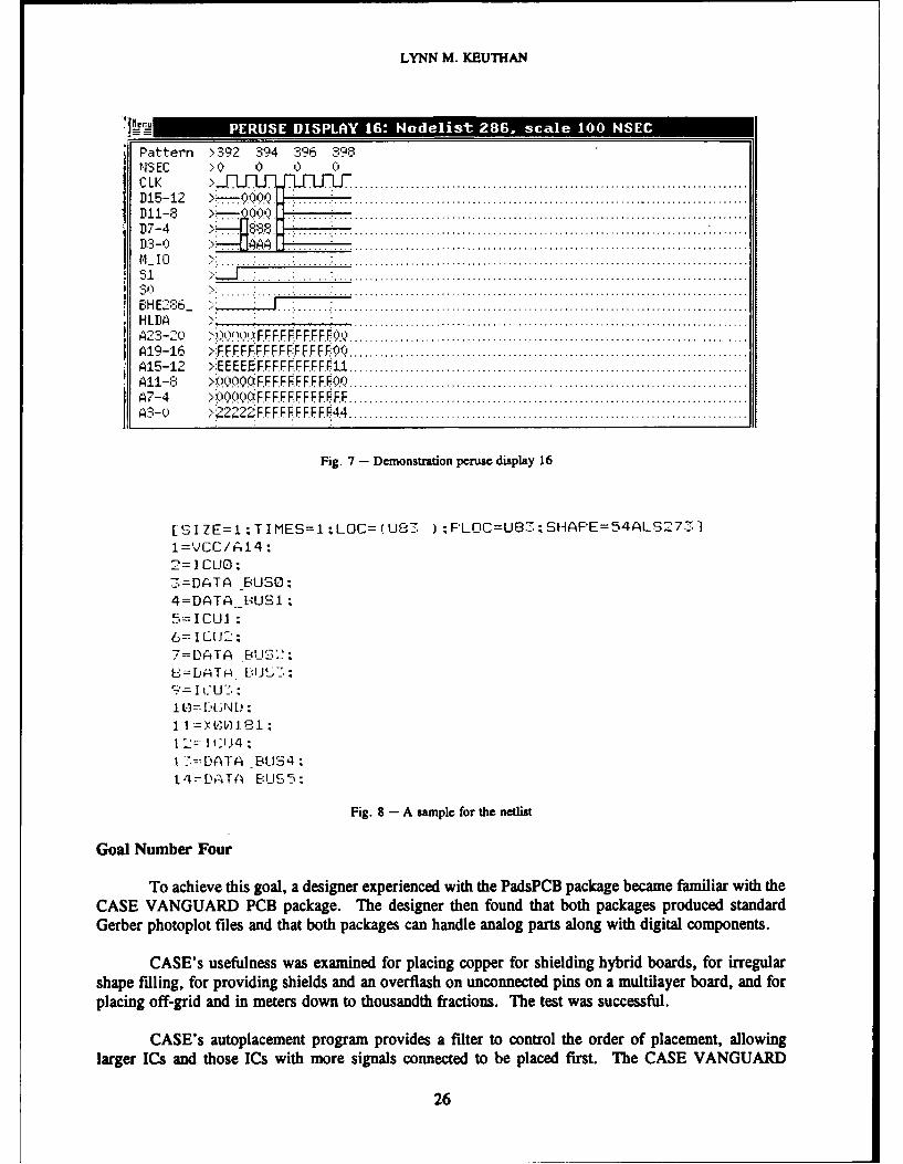
LYNN M. KEUTHAN
. E- II . A
Pattern ,392 3 94 _.'ISEC > 0 0 ,0 1C L K >. .............................................................................D 1 5 - 1 2 > ............................................................... .. ...................D 1 1 - 8 ... .............................................................................D7-4 " °
1 13 - 0 .. .' ".: . . . . . . . . . . . . . . . . . . . . . . . . . . . . . . . . . . . . . . . . . . . . . . . . . . . . . . . . . . . . . . . . . . . . . . . . . . . . . .i I0 "OS l I > ... .. ..... .: ........:. ................................................................................'. .. . ..
H L B A > L ... ..... . .. . ... " ...............................................................................
H L . . >D A;0 !, : : Q ..............................................................................A1-23 -2 F0 FE F'XI:FEFF F ; ( ..............................................................................
A15-12 >XE EE E f P FI FF F F FF I P 1, ..............................................................................A 1 1- 8 Q 0 0 0 F F F F F F F F F P ........................................ ......................................A 7- 4 >i)()0Q 6 FF F F F FF F r F F ..............................................................................A3 - 0 > 2 2 F F F I F F F F FF 44 ..............................................................................
Fig. 7 - Demonstration peruse display 16
[SIlZE=1 zT IMES=I zLOC= (USS- )F'LOC=U83 S1AF'E=54ALS73
1=VCC/A14;
-. =DATA _BUS-30:
4=DATA [BUSI:,-=ICUI-
6=I1C J2:7=DATA -BUS'_-';BS=DjATFA B!J--...
.
E-IIU .
Q ' =-II.'U -_, :
1 12- , - I'4
1 -'=-DATA _BUS4t4=DATA E:US5 ;
Fig. 8 - A sample for the ntlist
Goal Number Four
To achieve this goal, a designer experienced with the PadsPCB package became familiar with theCASE VANGUARD PCB package. The designer then found that both packages produced standardGerber photoplot files and that both packages can handle analog parts along with digital components.
CASE's usefulness was examined for placing copper for shielding hybrid boards, for irregularshape filling, for providing shields and an overflash on unconnected pins on a multilayer board, and forplacing off-grid and in meters down to thousandth fractions. Thbe test was successful.
CASE's autoplacement program provides a filter to control the order of placement, allowinglarger ICs and those ICs with more signals connected to be placed first. The CASE VANGUARD
26
NRL REPORT 9271
package was also more automated since all the needed information is passed directly from the schematiccapture program.
Goal Number Five
This goal was designed to test the ability of the Teradyne system to add multiple power and signalplanes and to route a multilayer board. Also tested was the ability to create varying pad sizes for pinsand to produce artwork for both surface-mount technology and Gerber photoplotting.
Among the items provided by Teradyne for the test was a copy of the schematic entry and PCBlayout system for the PC. The complex schematic used for Goal No. 2 was also used for Goal No. 5.
A 135-pin 80386 PGA layout model was modified to a 149-pin PGA layout model for the 82389device. All similar logic gates were automatically packaged together with the same reference designators.The components were manually placed optimally (with understanding of the purpose of the circuit).Analog and clock lines were manually routed also. Because of circuit complexity, 8 megabytes ofextended memory were needed for autorouting. The layout, with manually routed signals, was sent toTeradyne for routing to be completed with the autorouter. Artwork was produced for an 8-layer boardcomprising four signal layers, one GND layer, one +5 Vdc layer, one analog GND layer, and one layerproviding ± 12 Vdc.
Goal Number Six
The importance of this goal arises from the fact that a substantial amount of analog-related designand testing is done by Code 5740. In support of this work, a contract is being negotiated for an analogdesign and simulation system. A system produced by Analog Design Tools (ADT) proved to be one oftwo systems with extensive capability. This company also agreed to contract out work to recognizedexperts in vacuum tubes and relays to provide reliable models of such vintage 1920 devices. Anotherreason for seeking an interface with ADT is their unique menu-driven interface, an interface not availablefrom any other simulation package.
With the CASE VANGUARD schematic entry, a designer can build circuits that include bothanalog and digital parts. The system provides a shell around the schematic entry portion. CASE allowsthe designer to run SPICE and PSPICE directly from its menu. Because ADT is based on the SPICEsimulator developed at the University of California at Berkeley, ADT's package can also be run from theCASE menu. Digital input to DAC devices is provided through the CASE system, and analog signalsto A/Ds are, stepwise, linearly integrated to provide the digital information back to CASE after analogsimulation.
Also, Teradyne already has contracts with customers that are running both analog and digitalsimulations through the use of the digital simulation capability of the Teradyne system, mated with ADT'sanalog simulation system. The CASE VANGUARD schematic entry is the interface for this combination.
Goal Number Seven
The schematic used in this goal was the one used for Goal No. 3. Two digital interfaces wereused in the circuit. One of these used the Multibus II standard interface. Protocol for this interface ishandled by Intel's Message Passing Coprocessor (MPC) chip, the 82389, a 149-pin device. Forsimulation purposes, Teradyne uses hardware modeling for complex microprocessor parts; actual partsare used in the hardware modeler.
27
LYNN M. KEUTHAN
The hardware modeler is run on a VAXStation other than the Model 3100 supplied by Teradynefor the evaluation. The modeler interfaces through either the Q-Bus or through the Unibus. There is nobus structure in the 3100; it has an SCSI port. The modeler is nonportable. To watch a simulation withthe 82389 or another complex microprocessor requires continuing the evaluation at Teradyne corporateheadquarters. In the actual test, an alternate approach was taken.
Teradyne had both software and hardware models of Intel's 80286 microprocessor. The companysimulated this circuit with the hardware modeler at their headquarters. The hardware model ran exactlyas the software model. It was concluded that all software overhead for the hardware models wastransparently executed with respect to the circuit simulation. Thus, by using hardware modeling for anycomplex device, an accurate simulation displaying the complex signal-timing patterns could be obtained.
Goal Number Eight
This goal was designed to examine the ability of a designer to determine functionality fromexamining outputs of a circuit with known inputs. It was established that the system's hardware modeleris ideally suited for this purpose. Any existing digital hardware can be mounted on the hardwaremodeler. Leads can then be connected to all inputs and outputs. Inputs can be generated from thecomputer, and outputs can be monitored on the timing diagram. Additional tools exist for generatingmultiple input patterns automatically. This considerably reduces the time required to generate test results.
Figure 9 is a diagram of the counter/timer circuit that was used to test the acheivement of thisgoal. The circuit was entered into the CASE schematic entry system. Inputs were then applied to thecircuit to test how well the goal might be realized in an individual circuit.
Figures 10 through 13 show the hard copy simulation results. One input causes the outputs tosequence through a counting pattern at the same rate as the second input. By assuming that this circuitwas actual hardware and that the hardware could be broken down into the three parts identified withblocks on the circuit, a second set of simulations was run with a subset of the circuit. The set of hardcopies indicates how, by using this approach, a large amount of information can be accumulated withrespect to circuit functionality.
Additional Results of the Evaluation
Along with the information derived and discussed in the preceding paragraphs, the followingfeatures were found to be valuable assets in the schematic design process:
" Teradyne's Electrical Rule Checker (ERC) provided error and warning messages about realcircuit design problems that would have led to unreliable operation. The ERC identifiedproblems with:
" Mixing technologies," Multiple outputs, tied together without tri-state outputs," Low driving current," Open collector outputs, tied to signals driving both to VCC and GND," Excessive capacitance on lines," Signals without sources," Signals without input loading.
* Teradyne's toll-free customer support was able to provide ready answers to questions onsoftware operation. Directions were given on where to locate operations on the menu, whatquick-and-easy commands were available without the menu, and clarification of differencesencountered when using different operating systems.
28
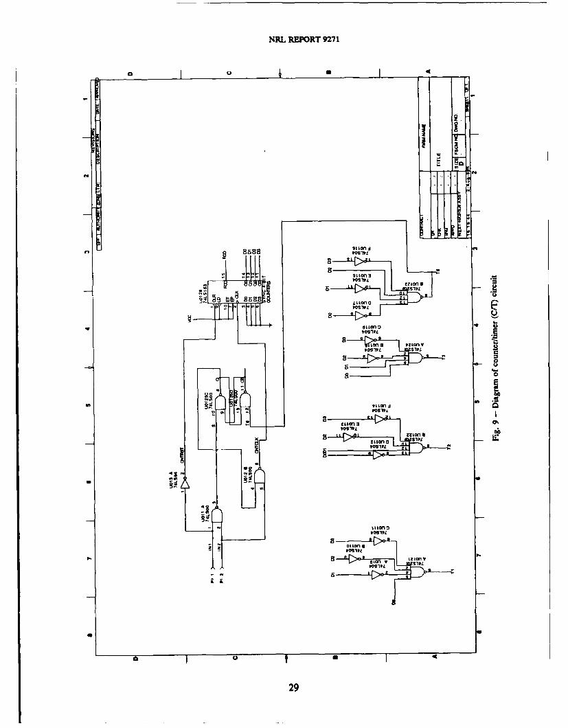
NRL RMPRT 9271
('4L
monns )?9n,O1P
LLL n-OIW
a -L~ jU, 0,ft3
b a - 8 L
0~ - :ZL'1 6
229
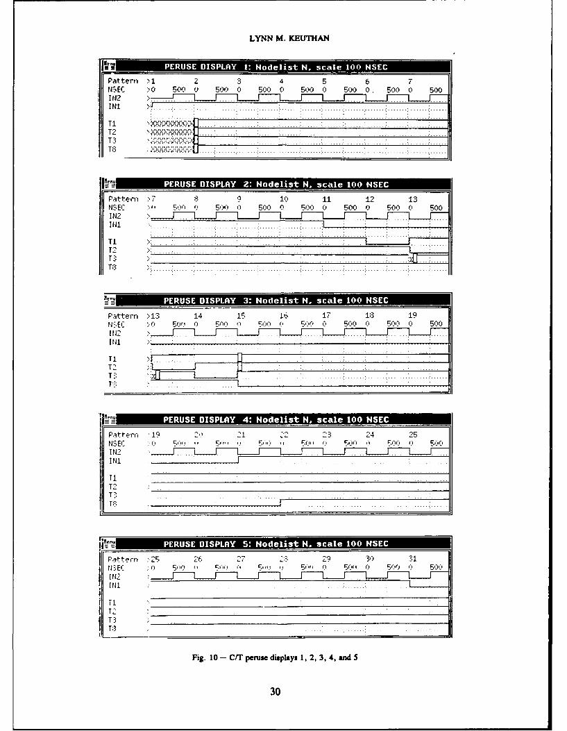
LYNN M. KEUTHAN
Pattern >1 234 5 6 7tISEC '0 50d0 500 0 500 0 5OO 0 S00 0. 50o 0 500IrJ2
TI
Pattern >7 9 10) 11 12 1351"'1 '~' 0 500 0 500 o 500 Soo50 0 500
I NI
TI
T:3
Z. ....... .... .... . .. . .....
Pa-ttern )13 14 15 16 17 183 19N :El ErIf f) % 50" 0 0 500 01 500,- 0 5001 Q
T11
T::
It l
Patte~rn 119 -~ 1 24 25
?iI 2'' .... . ii,- - --- ii- - -tL-r r ri- ,J -I NI
T1T
Fatt rn ;25 26 27 2329 30 31
USE' 5 ' 5'' 5.~ ''Q 5'' 0 500
Fig. 10 - C/T peruse displays 1, 2, 3, 4, and 5
30
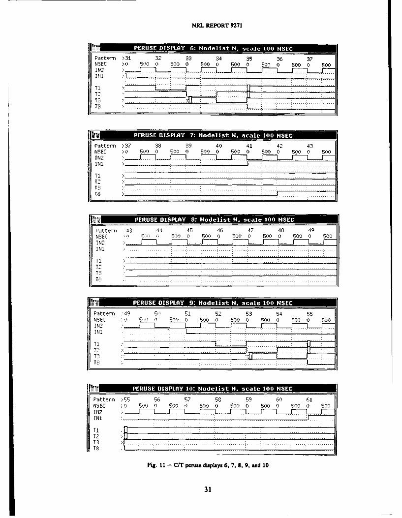
NRL RE-PORT 9271
Pattern >31 32 33 34 35 36 37SEfl >0 51)o 0 500 0 So0 Q S00 0 500 0 500 0 500
I1
T -i .. ... ...
Patte'rn >37 38 39 40 41 42 43NSEC > 0 5VO A 500 0 S00 0 50^0 0 500 0 5-00 0 510
IN .. . . . . . . .. . . . . . . . .. . . .. . .
Patter~n '4: 44 45 46 47 48 49tJ'EC In) SOO.' 5 0 5(" 0 o 0 500 0 500 O 0 500
T I. . . . .. . . . . .. . . .. . .. . . . .. . . . . . .. . . ... .. .
T .. ... .. . . ...... . .
I'--E 5"' f) 97() 500 (1 500 0 500 0 50 0o ;500o
IN.
T; .... -. j
FPattern ~55 56 F57 53 59 60 61IJ3EC 0 5Q 0 500 0) 500) 0 5-00 0 50O0 500O 500Q112INI
T1T2 ..T3 I
Fig. I1I - CT peruse displays 6, 7,9, 9, and 10
31
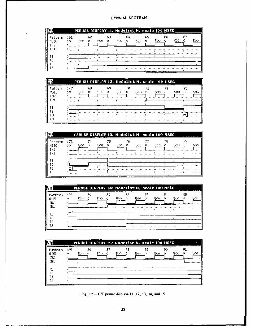
LYNN M. KE-UTHAN
PatteFrn >61 62 63 64 65 66 67NSEC >0~ 500 0 500 0 500 0 500 0 500 0 500o 0 500IN2 ... .
T
II 3n ... . .S.. . .. .. . ... ..
Paittern > 6 68 69 70 71 72 731 )3Ef C >0 500 Q 500 0 500 0 500 0 500 0 500 '0 500
IN
T1 -- -- -- - . ...
TI.. .. ........ ........... ... ........... ........ . ......
T -8 . . . . . . . . .. . . . . . . . . . . . ... . . . . . . . . . .. . . .. . . . .
Pa~tterni >791 -4 71 -6 e 6 75
fN3 EC >4 500 (1 500 0 500 0 5 00 4 '' 0 5002 0 E-00
INI
T-l
TI.
T 32
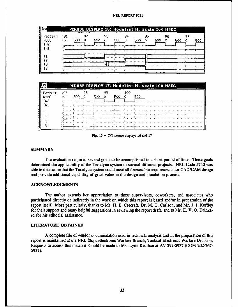
NRL REPORT 9271
Paten Q 92 93 9495 96 97Pattern .. I9
NSEC .0 500 0 500 0 500 0 500 0 500 0 500 0 500I N '2 .. ........I N1 >1J: : : : " :
.. . . ... . . ... . .. . .. . . . .. . . .. . . . . . .. . ... .. .... . . .. .... . .. .. ... .. ....,.. .. .. . ... . . .
TI" . J . .. . . . . .
P...ttern :.9. 9 99 100
N:3EC >( 500 0 500 0 500 0 500I.... . .. .... . .. .. . .. .. .. .. .. .. ... . ... . ... .. .. .. .. .. .. .. ... .. ..
- - - - ... .. .. .. ... . .. .. .. ... .. .. .. .. .. .. .. .. ... .._- . .. . . . . •.... . ..... . . . .. . ... . . . .... . . . . . . : . . . . .. . . . . . . . . . . . . . . . . . .. . . . . . . . . . . . . . . . . . . . . . . . . . . . . . . . .
TIT- , . . . . . . . . . . . . . . . ,. . . .-. . . . . . .-. . . . .. .' . . . . . . . .: . . . . . . . . . . . . . . . . . . . . . . . . . . . .* . . . . . . . . . . . . . . . . . .
T .. . . . . . . ... . . . . . . . . :.: . . .. .. . . . . . ... . . . . . ... . . . . . . ... . . . . . . . . . . . . . . . . . . . . . . . . . . . . . . . . . . . . . . . . . . . . . . . . . .T3T 8. . . . . .:. . . .•. . . .. . . .:. . . . . . . . . . . . . . . . . . . . . . . . . . . . . . . . . . . . . . . . . . . . . . . . . .. . . . . . .
Fig. 13 - C/T peruse displays 16 and 17
SUMMARY
The evaluation required several goals to be accomplished in a short period of time. These goalsdetermined the applicability of the Teradyne system to several different projects. NRL Code 5740 wasable to determine that the Teradyne system could meet all foreseeable requirements for CAD/CAM designand provide additional capability of great value in the design and simulation process.
ACKNOWLEDGMENTS
The author extends her appreciation to those supervisors, coworkers, and associates whoparticipated directly or indirectly in the work on which this report is based and/or in preparation of thereport itself. More particularly, thanks to Mr. H. E. Crecraft, Dr. M. C. Carlson, and Mr. J. J. Koffleyfor their support and many helpful suggestions in reviewing the report draft, and to Mr. E. V. 0. Drinka-rd for his editorial assistance.
LITERATURE OBTAINED
A complete file of vendor documentation used in technical analysis and in the preparation of thisreport is maintained at the NRL Ships Electronic Warfare Branch, Tactical Electronic Warfare Division.Requests to access this material should be made to Ms. Lynn Keuthan at AV 297-5937 (COM 202-767-5937).
33
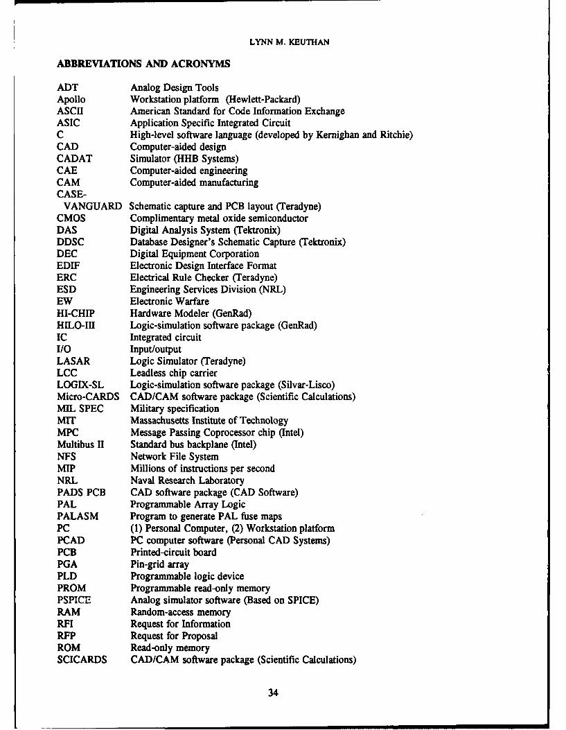
LYNN M. KEUTHAN
ABBREVIATIONS AND ACRONYMS
ADT Analog Design ToolsApollo Workstation platform (Hewlett-Packard)ASCII American Standard for Code Information ExchangeASIC Application Specific Integrated CircuitC High-level software language (developed by Kernighan and Ritchie)CAD Computer-aided designCADAT Simulator (HHB Systems)CAE Computer-aided engineeringCAM Computer-aided manufacturingCASE-VANGUARD Schematic capture and PCB layout (Teradyne)CMOS Complimentary metal oxide semiconductorDAS Digital Analysis System (Tektronix)DDSC Database Designer's Schematic Capture (Tektronix)DEC Digital Equipment CorporationEDIF Electronic Design Interface FormatERC Electrical Rule Checker (Teradyne)ESD Engineering Services Division (NRL)EW Electronic WarfareHI-CHIP Hardware Modeler (GenRad)HILO-III Logic-simulation software package (GenRad)IC Integrated circuitI/0 Input/outputLASAR Logic Simulator (Teradyne)LCC Leadless chip carrierLOGIX-SL Logic-simulation software package (Silvar-Lisco)Micro-CARDS CAD/CAM software package (Scientific Calculations)MIL SPEC Military specificationMIT Massachusetts Institute of TechnologyMPC Message Passing Coprocessor chip (Intel)Multibus II Standard bus backplane (Intel)NFS Network File SystemMIP Millions of instructions per secondNRL Naval Research LaboratoryPADS PCB CAD software package (CAD Software)PAL Programmable Array LogicPALASM Program to generate PAL fuse mapsPC (1) Personal Computer, (2) Workstation platformPCAD PC computer software (Personal CAD Systems)PCB Printed-circuit boardPGA Pin-grid arrayPLD Programmable logic devicePROM Programmable read-only memoryPSPICE Analog simulator software (Based on SPICE)RAM Random-access memoryRFI Request for InformationRFP Request for ProposalROM Read-only memorySCICARDS CAD/CAM software package (Scientific Calculations)
34
NRL REPORT 9271
SOP Small outline packageSPICE Simulator software (University of California at Berkeley)SQL Struatured Query LanguageSUN Workstation platform (Sun Microsystems, Inc.)Susie Logic-Simulation package (ALDEC)TEW Tactical Electronic Warfare (NRL)TSSI Test Systems Strategies, Inc.ULTRIX Operating System (Digital Equipment Corporation version of UNIX)UNIX Operating system (AT&T Bell Labs)VLSI Very large scale integrationVMS Operating system (Digital Equipment Corportion)VUP VAX Unit of Performance
35
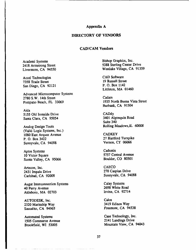
Appendix A
DIRECTORY OF VENDORS
CAD/CAM Vendors
Academi Systems Bishop Graphics, Inc.2418 Armstrong Street 5388 Sterling Center DriveLivermore, CA 94550 Westlake Village, CA 91359
Accel Technologies CAD Software7358 Trade Street 19 Russell StreetSan Diego, CA 92121 P.O. Box 1142
Littleton, MA 01460Advanced Microcomputer Systems2780 S.W. 14th Street CadamPompano Beach, FL 33069 1935 North Buena Vista Street
Burbank, CA 91504Aida5155 Old Ironside Drive CADdySanta Clara, CA 95054 3401 Algonquin Road
Suite 340Analog Design Tools Rolling Meadows,IL 60008(Valid Logic Systems, Inc.)1080 East Arquez Avenue CADKEYP. 0. Box 3422 27 Hartford TurnpikeSunnyvale, CA 94088 Vernon, CT 06066
Aptos Systems Cadnetix10 Victor Square 5757 Central AvenueScotts Valley, CA 95066 Boulder, CO 80301
Artecon, Inc. CAECO2431 Impala Drive 270 Caspian DriveCarlsbad, CA 92008 Sunnyvale, CA 94088
Augat Interconnection Systems Calay Systems40 Perry Avenue 2698 White RoadAttleboro, MA 02703 Irvine, CA 92714
AUTODESK, Inc. Calos2320 Marinship Way 3419 Edison WaySausalito, CA 94965 Freemont, CA 94538
Automated Systems Case Technology, Inc.1505 Commerce Avenue 2141 Landings DriveBrookfield, WI 53005 Mountain View, CA 94043
37
LYNN M. KEUTHAN
Computervision Innovative Computer-Aided100 Crosby Drive Technology, Inc.Bedford, MA 01730 14979 Prairie Avenue
Lawndale, CA 90260Daisy Systems700 Middlefield Road Intergraph, Inc.Mountain View, CA 94039 One Madison Industrial Park
Huntsville, AL 35807Dasoft resign Systems1827B Fifth Street Lucasfilm LimitedBerkeley, CA 94706 P. 0. Box 2009
San Rafael, CA 94912Data Development Corporation1717 South Orange Avenue Mentor Graphics, Inc.Suite 200 8500 S.W. Creekside DriveOrlando, FL 32806 Building 1
Beaverton, OR 97005Design Computation, Inc.10 Frederick Avenue OmationNeptune, NJ 07753 1210 East Campbell Road
Suite 100Douglas Electronics Richardson, TX 75081718 Marina BoulevardSan Leandro, CA 94577 Optima Technology
900 Middlesex TurnpikeFuturenet/Data I/O Corp. Building 59310 Topanga Canyon Boulevard Billerica, MA 01821Catsworth, CA 91311
OrCad Systems, Inc.GenRad, Inc. 1094 S.W. Baseline Street300 Baker Avenue Suite 500Concord, MA 01742 Hillsboro, OR 97123
Great SoftWestern PAFEC, Inc.270 West Hickory Street 5550A Peachtree ParkwaySuite 202 Technology Park, AtlantaDenton, TX 76201 Norcross, GA 30092
Hewlett-Packard, Inc. Personal CAD Systems1507 Page Mill Road 1290 Parkmoor AvenuePalo Alto, CA 94304 San Jose, CA 95126
HHB Systems Phase Three Logic1000 Wyckoff Avenue P. 0. Box 985Mahwah, NJ 07430 Hillsboro, OR 97123
IBM Corporation Phoenix Data Systems400 Columbus Avenue 2500 Grant RoadValhalla, NY 10595 Mountain View, CA 94043
38
NRL REPORT 9271
Quadtree Software Corporation Versacad(Will be Silocon West Corp.) 7372 Prince Drive5150 E. Pacific Coast Highway Huntington Beach, CA 92647Suite 320Long Beach, CA 90804 Viewlogic Systems
275 Boston Post Road, WestRacal-Redac, Inc. Marlboro, MA 017524 Liberty WayWestford, MA 10886 Visionics
343 Gibraltar DriveRoyal Digital Systems Sunnyvale, CA 940893600 West Bayshore RoadPalo Alto, CA 94303 Wire Graphics
95 Sherwood AvenueScientific Calculations, Inc. Farmingdale, NY 117357635 Main StreetFishers, NY 14453 Vendors Supplying CAD/CAM Products.
Documentation and PlatformsShared Resources3047 Orchard Parkway AldecSan Josd, CA 95134 3525 Old Conejo Road, #111
Newbury Park, CA 91320DSilvar-Lisco, Inc.1080 March Road Digital Equipment CorporationMenlo Park, CA 94025 Continental Blvd. MKO1IW83
Merrimack, NH 03054-9987SoftCircuits701 N.W. 13th Street Interleaf, Inc.Suite C-4 10 Canal ParkBoca Raton, FL 33432 Cambridge, MA 02141
Spectrum Software Logic Automation, Inc.1021 South Wolfe Road P. 0. Box 310Sunnyvale, CA 94086 Beaverton, OR 97075
Tektronix, Inc. Sun Microsystems, Inc.CAE Systems Division 2550 Garcia Avenue700 Professional Drive Mountain View, CA 94043Gaithersburg, MD 20877-6026
Xerox CorporationTeradyne 800 Long Ridge RoadDesign & Test Automation Stamford, CT 06904321 Harrison AvenueBoston, MA 02118
Valid Logic Systems, Inc.2820 Orchard ParkwaySan Josd, CA 95134
39
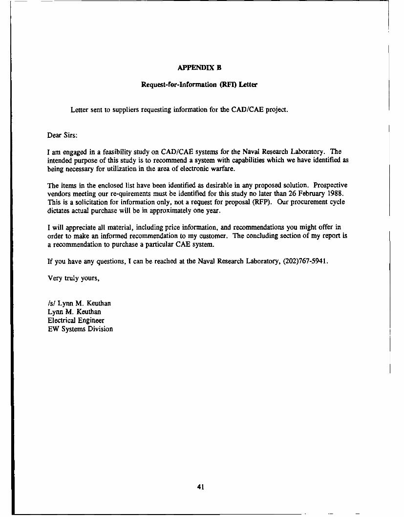
APPENDIX B
Request-for-Information (RFI) Letter
Letter sent to suppliers requesting information for the CAD/CAE project.
Dear Sirs:
I am engaged in a feasibility study on CAD/CAE systems for the Naval Research Laboratory. Theintended purpose of this study is to recommend a system with capabilities which we have identified asbeing necessary for utilization in the area of electronic warfare.
The items in the enclosed list have been identified as desirable in any proposed solution. Prospectivevendors meeting our re-quirements must be identified for this study no later than 26 February 1988.This is a solicitation for information only, not a request for proposal (RFP). Our procurement cycledictates actual purchase will be in approximately one year.
I will appreciate all material, including price information, and recommendations you might offer inorder to make an informed recommendation to my customer. The concluding section of my report isa recommendation to purchase a particular CAE system.
If you have any questions, I can be reached at the Naval Research Laboratory, (202)767-5941.
Very truly yours,
/s/ Lynn M. KeuthanLynn M. KeuthanElectrical EngineerEW Systems Division
41
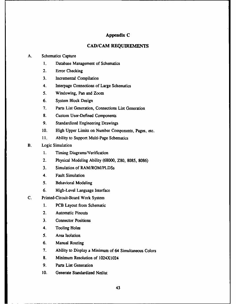
Appendix C
CAD/CAM REQUIREMENTS
A. Schematics Capture
1. Database Management of Schematics
2. Error Checking
3. Incremental Compilation
4. Interpage Connections of Large Schematics
5. Windowing, Pan and Zoom
6. System Block Design
7. Parts List Generation, Connections List Generation
8. Custom User-Defined Components
9. Standardized Engineering Drawings
10. High Upper Limits on Number Components, Pages, etc.
11. Ability to Support Multi-Page Schematics
B. Logic Simulation
1. Timing Diagrams/Verification
2. Physical Modeling Ability (68000, Z80, 8085, 8086)
3. Simulation of RAM/ROM/PLDSs
4. Fault Simulation
5. Behavioral Modeling
6. High-Level Language Interface
C. Printed-Circuit-Board Work System
1. PCB Layout from Schematic
2. Automatic Pinouts
3. Connector Positions
4. Tooling Holes
5. Area Isolation
6. Manual Routing
7. Ability to Display a Minimum of 64 Simultaneous Colors
8. Minimum Resolution of 1024X1024
9. Parts List Generation
10. Generate Standardized Netlist
43
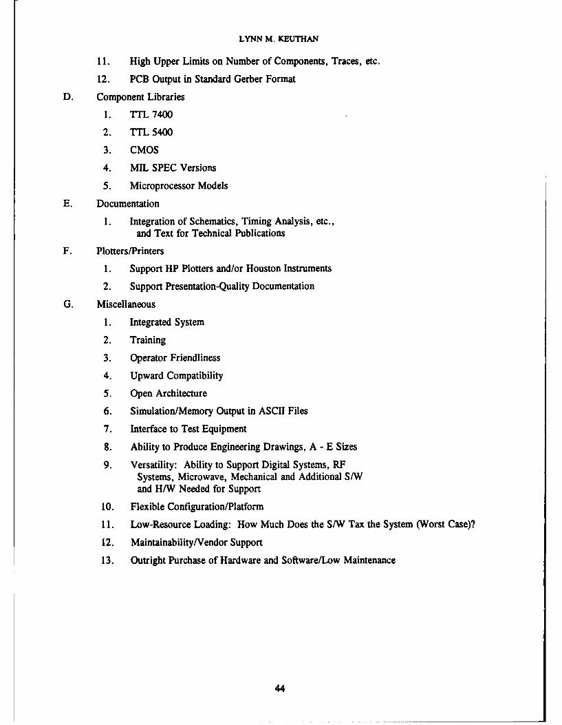
LYNN M. KEUTHAN
11. High Upper Limits on Number of Components, Traces, etc.
12. PCB Output in Standard Gerber Format
D. Component Libraries
1. ITL 7400
2. FTTL 5400
3. CMOS
4. MIL SPEC Versions
5. Microprocessor Models
E. Documentation
1. Integration of Schematics, Timing Analysis, etc.,and Text for Technical Publications
F. Plotters/Printers
1. Support HP Plotters and/or Houston Instruments
2. Support Presentation-Quality Documentation
G. Miscellaneous
1. Integrated System
2. Training
3. Operator Friendliness
4. Upward Compatibility
5. Open Architecture
6. Simulation/Memory Output in ASCII Files
7. Interface to Test Equipment
8. Ability to Produce Engineering Drawings, A - E Sizes
9. Versatility: Ability to Support Digital Systems, RFSystems, Microwave, Mechanical and Additional S/Wand H/W Needed for Support
10. Flexible Configuration/Platform
11. Low-Resource Loading: How Much Does the S/W Tax the System (Worst Case)?
12. Maintainability/Vendor Support
13. Outright Purchase of Hardware and Software/Low Maintenance
44
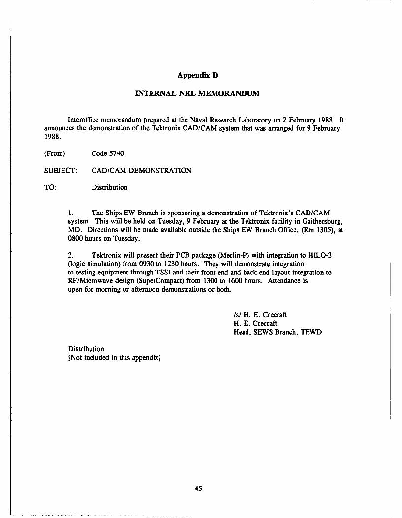
Appendix D
INTERNAL NRL MEMORANDUM
Interoffice memorandum prepared at the Naval Research Laboratory on 2 February 1988. Itannounces the demonstration of the Tektronix CAD/CAM system that was arranged for 9 February1988.
(From) Code 5740
SUBJECT: CAD/CAM DEMONSTRATION
TO: Distribution
1. The Ships EW Branch is sponsoring a demonstration of Tektronix's CAD/CAMsystem This will be held on Tuesday, 9 February at the Tektronix facility in Gaithersburg,MD. Directions will be made available outside the Ships EW Branch Office, (Rn 1305), at0800 hours on Tuesday.
2. Tektronix will present their PCB package (Merlin-P) with integration to HILO-3(logic simulation) from 0930 to 1230 hours. They will demonstrate integrationto testing equipment through TSSI and their front-end and back-end layout integration toRF/Microwave design (SuperCompact) from 1300 to 1600 hours. Attendance isopen for morning or afternoon demonstrations or both.
/s/ H. E. CrecraftH. E. CrecraftHead, SEWS Branch, TEWD
Distribution[Not included in this appendix]
45
Appendix E
COMPARISON CHARTS
The numbering (A1-G13) of requirements in Fig. El in this appendix corresponds tothe numbers listed in Appendix C. The degree to which a specific requirement is met is rated from0 to 5 where 5 corresponds to a full meeting of requirements.
47
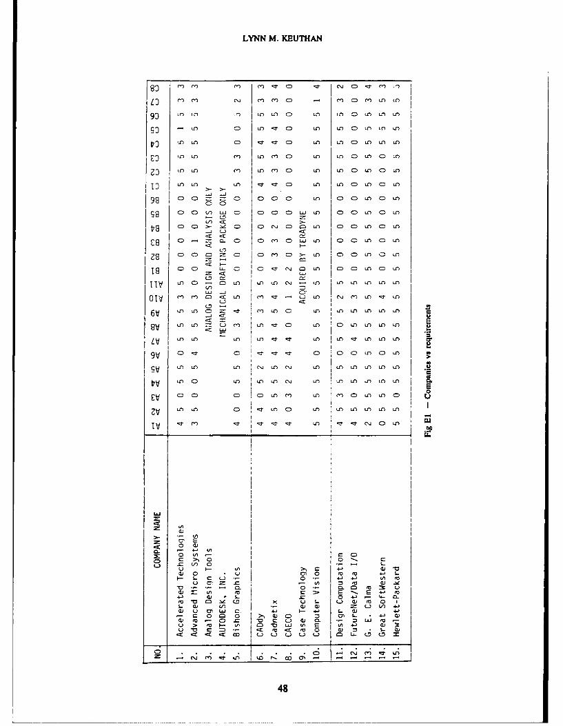
LYNN M. KEUTHAN
m M' m' r C .- C (J C:) -;:I- 'm
m ' (NJ ' C ') C) - M'* C) M' LO tA
93 LO ) !,~) LO LA CD L- 10 C:) t.0 LI in
so - in C:) LA - v C-) LA in C) LA LO iO
.7 n LA n C) -Z 'z1 C) in U-) C:) in in iO
£3 D LO (1) in m' a) LO in) C:) in C) LO
mLA n C') Ln m' C:) Ul LO C) Ln C:) LA)
13 LA) LA LA -~ :r CD LA L C) LO C) Ln
98 C) C) C) C ( C-- LA
98 C: L. ) C C) C) J Dw - CD C) in C) in
19 C) C) >- z C) C) e~j CD cm Ln CC)Ln C) in
CD~ '~ C:) C) m' C:) Lw L CD C) Uin CD in
CD) CC) m' cDmc)>- LA c) C) LA D) LA
CD C) CD :j C~ 9= F DCDL Da
iV LA C)D- Ln Ln LA c(NJ LA I"- Ln in LA LA
01 r m m) :x n MC' :J - n cj Mn mn -:I in
iinC ('inC) in in in in iO in
6V) *L' C)) in C) iniLO inn L- Im U' Ur L DL L nL
in iO n in in) ::J r in) IO ::I n in in
9v C) D C) r -z C:) C) C)- in c) in
1 9 n in in *C\) in C\J in in in, in in in
V i n in) C) inn C)j in in in in in in
iv L" LALnJ )i
0 L) a Co C >0 0 c
=) L n 0 S-L) c- :i) (1) CwJ 0 0) 0 cv (0 4-i S-.
- CL) I0 4i 4- 0i to
W /I c C~ E - E +.1 m
4 1i Q) S- -0 4-) 4- 0mv :0 ~CO x u S. L.) 0)c 0 1S- (U i) a) cu u V. ) i -
0) m 0 LJ C. Z-1 -, 4J ..~c 0C 1=0 1 cu 0 0) 0. LU
u > LA M- -/ 0 w v) El 4S (U 4..U~ ~ m ~ v~ 0 m) w-0~ ~ ) L)L) i Li 0 L- ( cm
48
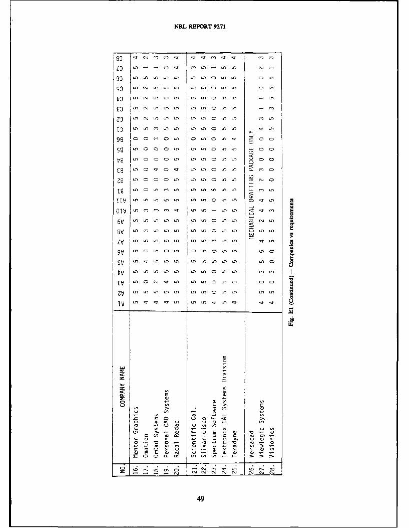
NRL REPORT 9271
LD U) m 't mI nI U Lfl mf C\h
go U) L U-) U) U) Ul U) C m Lfl C) LO
to LO " LI) U) U) m) LI C ) u) Cn 14)
E3 Uf) C\j LO) U) LO Ur) U) C Uf) Lo m-
3 ) (n J U~ C) ) UO U) U0 C ) I ) -o I)m
10 LnJ U) U) Ln LO) LO C U) U) -I) U
ID U) C)C)U ) U) U') CD m) It 5 C)C
98 C CD c) U-) M U') CD U) m C C)
m8Il CC U LO U) C) Ln U) LU CD CD
m) CC ) u-) CD m) U n~ m CD
U) C) cD CD un U) Lo CD m) U) 0. C
19 ) CD CO C U) UO LO C U) U) (\J C
18V LI) CO U) C) U- ) m U) CD U) LLO CZ ) U-)
01v m) m) en mI ,z Ll U-) C m) <) E
6V U) m nmm O) C Lo U)
9V CIO mL LI) U) U) Ln CD U Lo L-) U) U)
LV U) Lo u- ) ln U) L) en) U) U) -zr U)
9 ) Lnc- U) c) U) C U) C ) Lo U) L C) a
LO 'LO UO LO U) U)U U ) ) C 0
U-) U) UO U) U) U) UO CDO U O m) (I)
EV U) CD (J ;I UO UO U) C= m) L C C)
2 U)L U) U) UO L-0 U) Un) C o U) U U')
IV U- !: zr -I O L ,r L
E cu
Ul) 4-)>
(0 4JL LLU U~C E C= ) 04- -C>0. aj <c u 00 L.)(a 4-) u ro 0 U) LV)S- LM V U
(. 0 c, (1 4 J VS. 0 C ~)S - 0 u 00 C-
0-Va 0- Cr - .V ra -04-) (a) )V) rkW> 4a( nU0 ma L S.. 0 (- ) - .c s-GO) E s-. wJ ma U 0 CL a) o)
C> CO la V) U) U) I--~
0; .O , 0 C; C 1; L) LO o- -\(J CNJ (NJ (NJ (NI (NJ (NJ (N
49
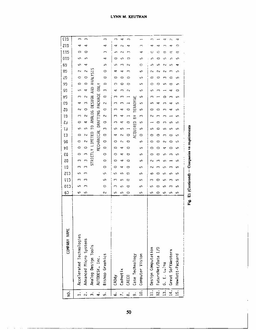
LYNN M. KEUTHAN
151 CD (n Lnj (n ' -ID c C C
09IS in -Z D C) 0-0 in in 0D u) in in
69 u) 3- mn nj 0 -n in C\J in zr
00 -Jj 0~ 0 0 0 'T 00u m " n
00 C >-- 0: 000) CDC n 00 CDn c0 in
LC) I- 0f ml m nli in in r) - .- ~ CD
Lj
cn 0j cl 0D r M- 00 L m .- 0 ) m LnlO
in i - m in in) .-j M - in Zzr m in mnw0
0O c 0m . ()- 0- c, t m N 0zl n 0 ~ 0 0 m 0 in
- -C 2- : <r CD m -,I- CD m n 00 mJ m in
00 LU m 0 n ml 0n in 00 ' 0n m
j
13 CD m~ I- 0 cl 0 ~ CD i. 00 CD nC m CD in
in CD w C0D:J D Ln C D t- C -
mDm CD CD I- CD in CD CD in m in
m1) i m in in I CD in m 0 n n in
11 - mm in m in 0 in m.0 CDin m in
01TO min m m in c) in in 0 in m in
6) u-) fn u-) in n C0 in in D in in in
Ln
0 a
0 U' iC0D a > 0 0- C
_s-_ C i 0 - .u I ( >) C -JWa) 0 C)0 ra tro 4-j 5-
I- L LC 4~J + LCAU~~~ eC CW A fl I )-
-0 0*- C) cc M. Ua) 2: U ~c E -- E 4-' eu4-. a) S- A= .C 4-'.- 4- 0-mV =~ cm x iD S- LU cu- 0 0 1S- cu iv C) ) m: .J 4-'
) VU OL 0- 4-' F- 4-' c C)12 C- 00C 0 >1 CU 0CD 0) L- 4-. C
v oC) f- -0 aC tj C a) 0- ; = U (aU > ro F- Ln 0 D V ij Ln E (A 4-I )
Ur (a <0 r V 0 Q) * S.- C
cr ~ m u n '0 r ~.. - - -. CD
50
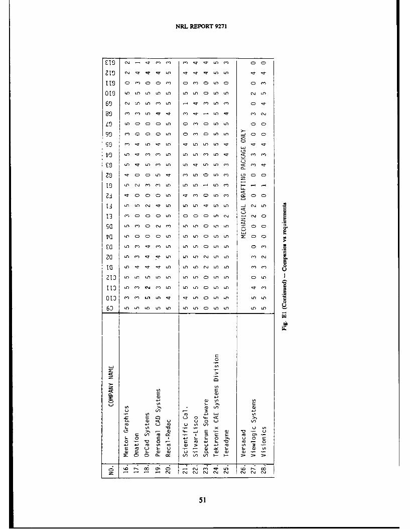
NRL REPORT 9271
ecj m rn mm: CT Ln m c:)C:
CI > C- m o m: cn Cm C) in cD cm
019) LO LO Ul an Lf an) n) (= LCn an c~j an
69~ "in a-n m in - m in m CD ::I-
m9 mn inn -: - - - iO -.t m C\J
i nc c c) i: C n cm c i- n a) cc>
9cc MiDCDC n Cm) M C n in __ c)cD
99 m t~- in -Z- an -:I in Uin in - - z
in -zl- m m in in) in m in -r m mo
in) - in m in in r in in m m T
~-t Cc CD M- m inc C:)n m O c:)c:
a9 n C\Ji m m in in in) .- U- m i -
U-U
in m c. m) in m CDin in CD Cc
in Ucc i~ zl n in inc Zzin in -j cc
13 i m C DC m CD CD iCD in in cmiC:
::2E t
Co U-) m - inn in in C). in n m CDm
ZoJ n in) -- :I-n in in cj in in m in
113 U- n m n aL'n m n in in CD in in CD ml
0 mnm ij in u) Ln in c in in in i
0
60~ u- in an in in in u-n c in in -
bw
CC Ln
IA
a) 4V) * s.- >1 E
'A >) n a)
IAut 4- LaL a/I
Lu IA L/)
C. ) E a) 4-.,2-a -a in 0 c~ m-u~CC5- CI J C 5 0>~ u 0 c
o~ 0- CM 4- S- fu-4-a M- ul L)t a 41i (0 LAa (05-) S.- U *- - a) -V S.- £ aa) E S. ) a) U - CL a) CU a...2: Cc 0 a- V) in Vn - I
51
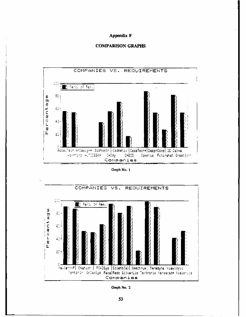
Appendix F
COMPARISON GRAPHS
COQMPANIES VS. REQLUIREMENTS
a) Ec1r)
^ r ,. CsEC ec Depvs Futre Gre~1at-
Graph No. 1
COMPANIES VS. REQUIREMENTS
AL Per:. : e.
4-)
0.
-elv.-PI Oma~tvo 1,0DS~% IScierftCall S~ectrumI Teradjne \~iew'locic,:0rBjj Paca1Redc Silva!ALis Tektroriix Versacad* Visic'-:2
Co r.,, p a r ie
Graph No. 2
53
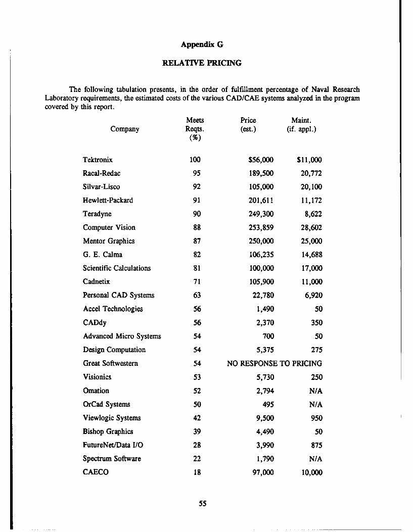
Appendix G
RELATIVE PRICING
The following tabulation presents, in the order of fulfillment percentage of Naval ResearchLaboratory requirements, the estimated costs of the various CAD/CAE systems analyzed in the programcovered by this report.
Meets Price Maint.Company Reqts. (est.) (if. appl.)
Tektronix 100 $56,000 $11,000
Racal-Redac 95 189,500 20,772
Silvar-Lisco 92 105,000 20,100
Hewlett-Packard 91 201,611 11,172
Teradyne 90 249,300 8,622
Computer Vision 88 253,859 28,602
Mentor Graphics 87 250,000 25,000
G. E. Calma 82 106,235 14,688
Scientific Calculations 81 100,000 17,000
Cadnetix 71 105,900 11,000
Personal CAD Systems 63 22,780 6,920
Accel Technologies 56 1,490 50
CADdy 56 2,370 350
Advanced Micro Systems 54 700 50
Design Computation 54 5,375 275
Great Softwestern 54 NO RESPONSE TO PRICING
Visionics 53 5,730 250
Omation 52 2,794 N/A
OrCad Systems 50 495 N/A
Viewlogic Systems 42 9,500 950
Bishop Graphics 39 4,490 50
FutureNet/Data I/O 28 3,990 875
Spectrum Software 22 1,790 N/A
CAECO 18 97,000 10,000
55
Appendix H
APPLICATION NOTE
by William D. Billowitch, Executive Vice President, Quadtree
Successful Board-Level Simulation Dependson Accurate Models
If you have ever designed a logic board and had the experience of having to wait for devicesamples to arrive before you could debug the board or became frustrated when wire-wrap boards wereassembled improperly (or when pins 1-8 and 9-16 of an IC socket were wired in reverse), or you had tofight to keep your favorite oscilloscope or logic analyzer from being "borrowed" by your friend in theother lab, you can appreciate the benefits of simulating your board design rather than developing thebreadboard.
In fact, many design and analysis decisions can be more easily handled through the use of logicsimulation rather than through more commonly used techniques. For example the problem of runningthe design over temperature or voltage to assure the design will work when stressed under actualoperating conditions.
Steps in Logic Simulation
With low-cost schematic entry stations and powerful supermicro workstations or shareablesupermini server processors, board-level logic simulation is in reach of every digital designer.
Performing board-level logic simulation on a workstation is not much different in principle thandoing test bench debugging. The difference is that different tools are used to accomplish the task.
The first step is to describe the design to the logic simulator. Unless you enjoy writing lengthy"from-to" lists of each componvnt's interconnectivity to other components, you begin by creating aschematic of the circuit on the workstation screen in an analogous manner to drawing it on paper. Thisinvolves using the CAE system's schematic capture software package. Once the circuit diagram isentered it is easily modified and you can generate draftsman-quality drawings from a plotter.
Most schematic capture packages perform an adequate job of allowing you to enter drawings.However, you may want to consider a few areas when making your selection:
* How much of a circuit can be viewed at once?
* How long does it take to pan or move a view of the drawing from one area to another?
0 How easy is it to move components on the screen? Do the connections snap into thecorrect position when moved?
* Can components and connections be easily duplicated or copied?
* Can symbols be easily created and entered into the schedule?
57
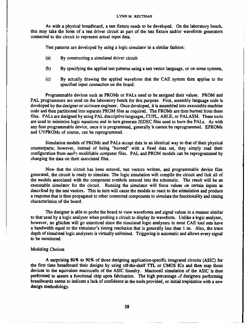
LYNN M. KEUTHAN
As with a physical breadboard, a test fixture needs to be developed. On the laboratory bench,this may take the form of a test driver circuit as part of the test fixture and/or waveform generatorsconnected to the circuit to represent actual input data.
Test patterns are developed by using a logic simulator in a similar fashion:
(a) By constructing a simulated driver circuit
(b) By specifying the applied test patterns using a test vector language, or on some systems,
(c) By actually drawing the applied waveform that the CAE system then applies to thespecified input connection on the board.
Programmable devices such as PROMs or PALs need to be assigned their values. PROM andPAL programmers are used on the laboratory bench for this purpose. First, assembly language code isdeveloped by the designer or software engineer. Once developed, it is assembled into executable machinecode and then partitioned into separate PROM files as required. The PROMs are then burned from thesefiles. PALs are designed by using PAL descriptive languages, CUPL, ABLE, or PALASM. These toolsare used to minimize logic equations and in turn generate JEDEC files used to burn the PALs. As withany fuse programmable device, once it is programmed, generally it cannot be reprogrammed. EPROMsand UVPROMs of course, can be reprogrammed.
Simulation models of PROMs and PALs accept data in an identical way to that of their physicalcounterparts; however, instead of being "burned" with a fixed data set, they simply read theirconfiguration from easily modifiable computer files. PAL and PROM models can be reprogrammed bychanging the data on their associated files.
Now that the circuit has been entered, test vectors written, and programmable device filesgenerated, the circuit is ready to simulate. The logic simulation will compile the circuit and link all ofthe models associated with the component symbols entered into the schematic. The result will be anexecutable simulator for the circuit. Running the simulator will force values on certain inputs asdescribed by the test vectors. This in turn will cause the models to react to the stimulation and producea response that is then propagated to other connected components to simulate the functionality and timingcharacteristics of the board.
The designer is able to probe the board to view waveforms and signal values in a manner similarto that used by a logic analyzer when probing a circuit to display its waveform. Unlike a logic analyzer,however, no glitches will go unnoticed since the simulated logic analyzers in most CAE tool sets havea bandwidth equal to the simulator's timing resolution that is generally less than 1 ns. Also, the tracedepth of simulated logic analyzers is virtually unlimited. Triggering is automatic and allows every signalto be monitored.
Modeling Choices
A surprising 80% to 90% of those designing application-specific integrated circuits (ASIC) forthe first time breadboard their designs by using off-the-shelf TTL or CMOS ICs and then map thosedevices to the equivalent macrocells of the ASIC foundry. Macrocell simulation of the ASIC is thenperformed to assure a functional chip upon fabrication. The high percentage if designers performingbreadboards seems to indicate a lack of confidence in the tools provided, or initial trepidation with a newdesign methodology.
58
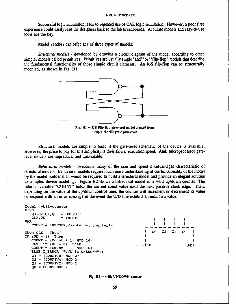
NRL REPORT 9271
Successful logic simulation leads to repeated use of CAE logic simulation. However, a poor firstexperience could easily lead the designers back to the lab breadboards. Accurate models and easy-to-usetools are the key.
Model vendors can offer any of three types of models:
Structural models - developed by drawing a circuit diagram of the model according to othersimpler models called primitives. Primitives are usually single "and""or""flip-flop" models that describethe fundamental functionality of those simple circuit elements. An R-S flip-flop can be structurallymodeled, as shown in Fig. H1.
Fig. Hi - R-S Flip-flop structural model created from2-input NAND grate primitives
Structural models are simple to build if the gate-level schematic of the device is available.However, the price to pay for this simplicity is their slower execution speed. And, microprocessor gate-level models are impractical and unavailable.
Behavioral models - overcome many of the size and speed disadvantages characteristic ofstructural models. Behavioral models require much more understanding of the functionality of the modelby the model builder than would be required to build a structural model and provide an elegant solutionto complex device modeling. Figure H2 shows a behavioral model of a 4-bit up/down counter. Theinternal variable "COUNT" holds the current count value until the next positive clock edge. Then,depending on the value of the up/down control time, the counter will increment or decrement its valueor respond with an error message in the event the U/D line exhibits an unknown value.
Model 4-bit-counter,PINS
Q3,Q2,QI,QO = OUTPUT;CLK,UD = INPUT; i
VARCOUNT = INTEGER;/*internal counter*/ I I I
When CLK Then ( I 03 02 01 00 IIF (UD = 1) Then I
COUNT = (Count + 1) MOD 16;ELSE if (UD = 0) Then --- clk U/O--COUNT = (Count - 1) MOD 16;ELSE X ERROR ("U/D is UNKNOWN");Q3 = (COUNT/8) MOD 2;Q2 = (COUNT/4) MOD 2;Q1 = (COUNT/2) MOD 2;QO = COUNT MOD 2;
Fig. H2 - 4-Bit UPIDOWN counter
59
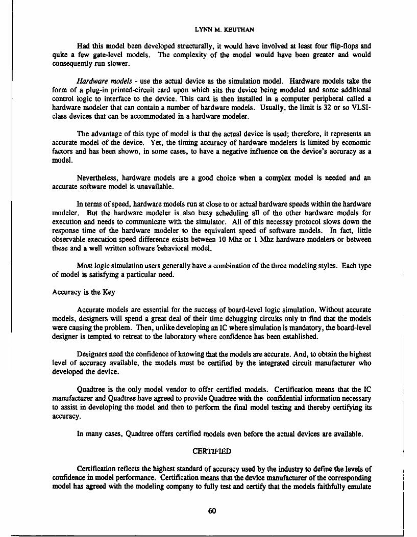
LYNN M. KEUTHAN
Had this model been developed structurally, it would have involved at least four flip-flops andquite a few gate-level models. The complexity of the model would have been greater and wouldconsequently run slower.
Hardware models - use the actual device as the simulation model. Hardware models take theform of a plug-in printed-circuit card upon which sits the device being modeled and some additionalcontrol logic to interface to the device. This card is then installed in a computer peripheral called ahardware modeler that can contain a number of hardware models. Usually, the limit is 32 or so VLSI-class devices that can be accommodated in a hardware modeler.
The advantage of this type of model is that the actual device is used; therefore, it represents anaccurate model of the device. Yet, the timing accuracy of hardware modelers is limited by economicfactors and has been shown, in some cases, to have a negative influence on the device's accuracy as amodel.
Nevertheless, hardware models are a good choice when a complex model is needed and anaccurate software model is unavailable.
In terms of speed, hardware models run at close to or actual hardware speeds within the hardwaremodeler. But the hardware modeler is also busy scheduling all of the other hardware models forexecution and needs to communicate with the simulator. All of this necessay protocol slows down theresponse time of the hardware modeler to the equivalent speed of software models. In fact, littleobservable execution speed difference exists between 10 Mhz or I Mhz hardware modelers or betweenthese and a well written software behavioral model.
Most logic simulation users generally have a combination of the three modeling styles. Each type
of model is satisfying a particular need.
Accuracy is the Key
Accurate models are essential for the success of board-level logic simulation. Without accuratemodels, designers will spend a great deal of their time debugging circuits only to find that the modelswere causing the problem. Then, unlike developing an IC where simulation is mandatory, the board-leveldesigner is tempted to retreat to the laboratory where confidence has been established.
Designers need the confidence of knowing that the models are accurate. And, to obtain the highestlevel of accuracy available, the models must be certified by the integrated circuit manufacturer whodeveloped the device.
Quadtree is the only model vendor to offer certified models. Certification means that the ICmanufacturer and Quadtree have agreed to provide Quadtree with the confidential information necessaryto assist in developing the model and then to perform the final model testing and thereby certifying itsaccuracy.
In many cases, Quadtree offers certified models even before the actual devices are available.
CERTIFIED
Certification reflects the highest standard of accuracy used by the industry to define the levels ofconfidence in model performance. Certification means that the device manufacturer of the correspondingmodel has agreed with the modeling company to fully test and certify that the models faithfully emulate
60
NRL REPORT 9271
their actual devices. In many cases, certified models will be available even before the device samplesare available from the IC manufacturer, thereby allowing the digital designer to design the latest devicesinto products sooner.
VERIFIED
Verification reflects the second highest standard of accuracy used by the industry to define levelsof confidence in model performance. Verification means that the device manufacturer of thecorresponding model has provided the modeling company with detailed proprietary information about themodeled device, including in many cases, test patterns but has not signed an agreement requiring theystate the models have been certified.
VALIDATED
Validation reflects the third highest standard of accuracy used by the industry to define the levelsof confidence in model performance. Test vectors are used that were developed with expertunderstanding of the functions and timing characteristics of each device. Validated models are sometimessubjected to tests that have been previously tested for accuracy. Validated models are directly comparedto the actual device by using a hardware modeler and represent the state of the art in behavioral modeltesting when verification or certification is unobtainable.
Figure H3 shows the certified model development cycle.
Quadtree Offers AccurateTEST Full-Function Models PROPRIETARYVECTORS I ........o i-Ic
SDEVELOPMENT I
DESIGNERS'S CHOICE ;,,
MODEL
rHARDWARE ]. , IC ]
| MODEL MODEL VENDOR I
Fig. H3 - Certified quadtree model development cycle
Designers' Choice
Designers have many options in selecting appropriate systems for their needs. The choices willfactor in cost, accuracy, and customer support. In an industry that changes so rapidly, it is best toevaluate carefully each vendor for its long-term commitment to the highest quality of products and forits support to customers throughout the design phase.
61
Appendix I
SYSTEM DESIGN AND DEVELOPMENT TOOLS, COMPUTER DESIGN
Worst-Case Timing Analysis Ensures Board Reliability*By Lauro Rizzatti and Mary Wasilewski
By accounting for component performance variations, worst-case timing analysis uncovers errorsthat wouldn't be discovered during breadboarding.
As printed circuit board designers continue pushing the limits of circuit performance, they facethe increasingly critical and demanding chore of verifying the timing of new designs. The potential fortiming problems that can devastate product-development timetables multiplies when designing a complexVLSI board, where custom and semicustom ICs interact with standard off-the-shelf components in adense, high-speed environment.
Subtle timing problems that produce marginal performance and intermittent failures are notapparent during the design and may not become evident until after volume production is in full swing andenough boards have gone through the test cycle to produce some meaningful statistics. Such marginalityand intermittent failures can severely depress production yields, tie up expensive technicians in difficultand time-consuming board diagnosis, and saddle a vendor with a high rate of field failures. In a fast-moving and highly competitive market, such problems can turn a promising new product into a costlyfailure.
Timing errors must therefore be identified and corrected before a design is released to production.Manual timing analysis of board designs containing tens or hundreds of thousands of gates, however, isa time-consuming task. And a hardi .. prototype-since it is only one physical implementation of thedesign-does not tell the designer whetier the design can tolerate all the timing interactions that can occuras components vary independently within their timing-specification ranges.
Some measure of a board's timing performance can be provided by software tools for timingverification, which analyze the topology of a design and calculate delays along the various paths in acircuit to predict likely timing problems. But these tools provide only a partial verification since theydo not include any analysis of a circuit's logic states. A timing verifier may analyze the circuit as thoughall data paths were enabled all the time, for example. In actual board operations, though, some paths cannot be enabled when other paths are active.
Because so many timing parameters are state-dependent, only a timing analysis that is performedas an integral part of logic simulation can ensure that board timing will be correct in actual operation.Although this combined logic simulation and timing analysis requires additional time and effort duringdesign, it results in a faster move into volume production and, thus, a shortened time-to-market. Thisprocess also ensures higher levels of product quality and reliability.
*Reprinted with permission from the November 15, 1987 issue of COMPUTER DEISGN, Copyright 1987, PennWell PublishingCompany, Advanced Technology Group.The authors arm applications engineers in the Design and Test Automation Group of Teradyne (Boston, MA).
63
LYNN M. KEUTHAN
Full worst-case timing analysis, a relatively compute-intensive process, does not have to be a partof early logic simulations, when a design is evolving rapidly. To get a rough measure of timingperformance at some intermediate stage of design, an engineer might simulate the design by using onlytypical timing values. Once the design has been fine-tuned and is considered near its final form,however, a complete worst-case simulation using minimum and maximum timing values provides finaldesign verification.
Structural and Functional Timing
The first requirement for combined logic simulation and worst-case timing analysis at the boardlevel is a simulation model of the board. This includes models of each component on the board, and net-list information of how the components connect one to another.
Generally, designers use a mix of modeling levels. Although board parts may be modeled at thetransistor level, they are more commonly modeled at higher levels (gate, functional or behavioral) toreduce simulation run time and memory requirements. When software models are not available,hardware modeling may also join the lineup with the electrical responses of a real device beingincorporated into the simulation.
The modeling language's ability to represent timing parameters accurately at every modeling leveldepends on whether or not it can express timing parameters and values functionally as well asstructurally. IC designers might model timing structurally, assigning independent delay values to eachprimitive within the device. But, board designers have no internal timing information on most of thecomponents on a board; they have only the pin-level-or functional-timing data available from a vendor'sspec sheet.
Functional timing parameters include input-to-output propagation delays, wire and loading delays,and input-to-input timing constraints such as setup and hold of data relative to the clock. Even when adevice's structural timing is known, the functional timing information found on a spec sheet is valuablefor true worst-case timing analysis because it reflects margining to account for lot variations and minormask changes as well as for the range of operating specifications.
Modeling Functional Timing
The more device models a designer can pull from the simulator's library, the better, since thesemodels typically include functional timing information. The designer will have to model devices notavailable in the model library. The vendor's spec book will likely include several pages of functionaltiming information, including pin-dependent and state-conditional delay values. A modeling languageflexible enough to let the designer include all relevant information into the timing model helps ensureaccurate timing analysis.
An essential aspect of modeling flexibility is the ability to model minimum, typical, and maximumdelay values based on device technology and fan-out. CMOS devices, for example, are extremely load-sensitive, and the simulator should be able to automatically calculate the appropriate minimum, typical,and maximum delays individually for each device based on the load being driven.
To achieve greatest modeling efficiency, the designer must specify functional device timing,generically and specifically. Generic specifications quickly characterize timing behavior common to aparticular device type, such as a 7474 flip-flop. But because a device's timing characteristics varyaccording to the technology used-Low-Power Schottky, Advanced Schottky or Fairchild AdvancedSchottky technology, for instance-these generic timing specifications should be expressed by using
64
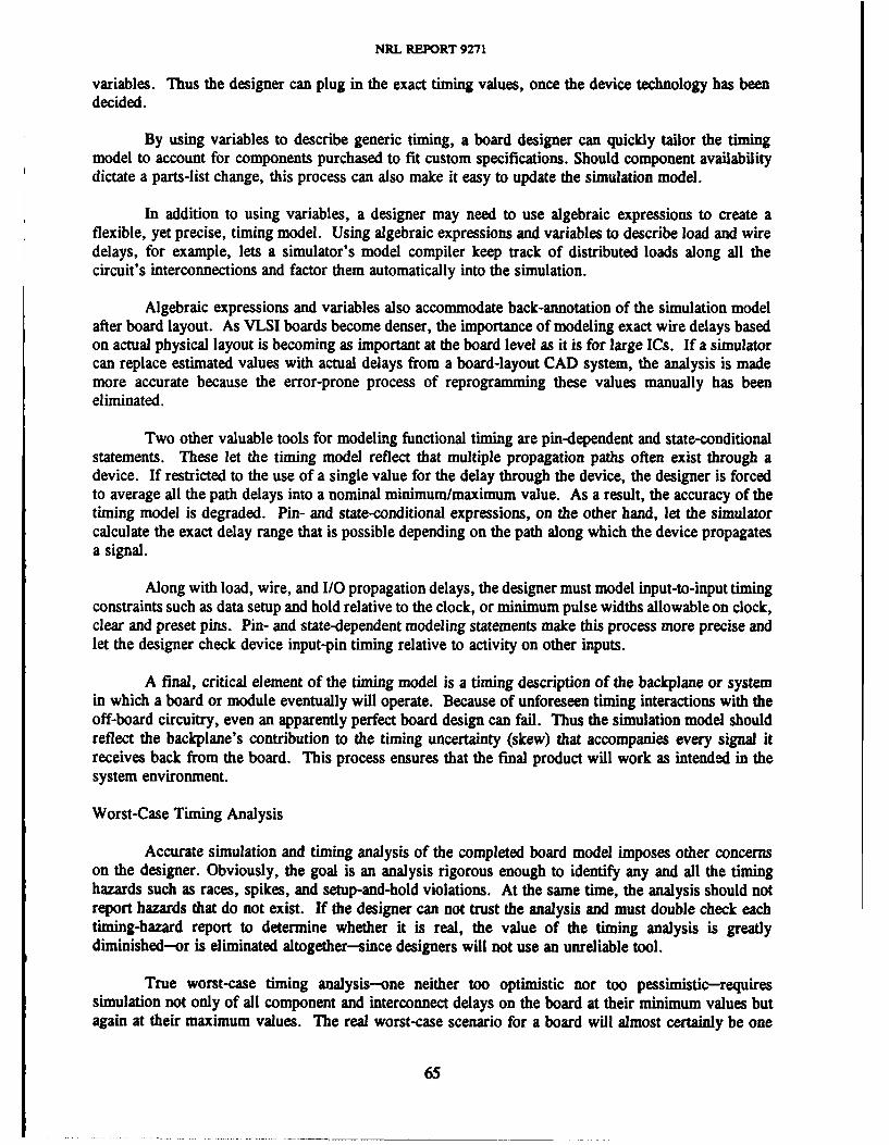
NRL REPORT 9271
variables. Thus the designer can plug in the exact timing values, once the device technology has beendecided.
By using variables to describe generic timing, a board designer can quickly tailor the timingmodel to account for components purchased to fit custom specifications. Should component availabilitydictate a parts-list change, this process can also make it easy to update the simulation model.
In addition to using variables, a designer may need to use algebraic expressions to create aflexible, yet precise, timing model. Using algebraic expressions and variables to describe load and wiredelays, for example, lets a simulator's model compiler keep track of distributed loads along all thecircuit's interconnections and factor them automatically into the simulation.
Algebraic expressions and variables also accommodate back-annotation of the simulation modelafter board layout. As VLSI boards become denser, the importance of modeling exact wire delays basedon actual physical layout is becoming as important at the board level as it is for large ICs. If a simulatorcan replace estimated values with actual delays from a board-layout CAD system, the analysis is mademore accurate because the error-prone process of reprogramming these values manually has beeneliminated.
Two other valuable tools for modeling functional timing are pin-dependent and state-conditionalstatements. These let the timing model reflect that multiple propagation paths often exist through adevice. If restricted to the use of a single value for the delay through the device, the designer is forcedto average all the path delays into a nominal minimum/maximum value. As a result, the accuracy of thetiming model is degraded. Pin- and state-conditional expressions, on the other hand, let the simulatorcalculate the exact delay range that is possible depending on the path along which the device propagatesa signal.
Along with load, wire, and I/0 propagation delays, the designer must model input-to-input timingconstraints such as data setup and hold relative to the clock, or minimum pulse widths allowable on clock,clear and preset pins. Pin- and state-dependent modeling statements make this process more precise andlet the designer check device input-pin timing relative to activity on other inputs.
A final, critical element of the timing model is a timing description of the backplane or systemin which a board or module eventually will operate. Because of unforeseen timing interactions with theoff-board circuitry, even an apparently perfect board design can fail. Thus the simulation model shouldreflect the backplane's contribution to the timing uncertainty (skew) that accompanies every signal itreceives back from the board. This process ensures that the final product will work as intended in thesystem environment.
Worst-Case Timing Analysis
Accurate simulation and timing analysis of the completed board model imposes other concernson the designer. Obviously, the goal is an analysis rigorous enough to identify any and all the timinghazards such as races, spikes, and setup-and-hold violations. At the same time, the analysis should notreport hazards that do not exist. If the designer can not trust the analysis and must double check eachtiming-hazard report to determine whether it is real, the value of the timing analysis is greatlydiminished-or is eliminated altogether-since designers will not use an unreliable tool.
True worst-case timing analysis-one neither too optimistic nor too pessimistic-requiressimulation not only of all component and interconnect delays on the board at their minimum values butagain at their maximum values. The real worst-case scenario for a board will almost certainly be one
65
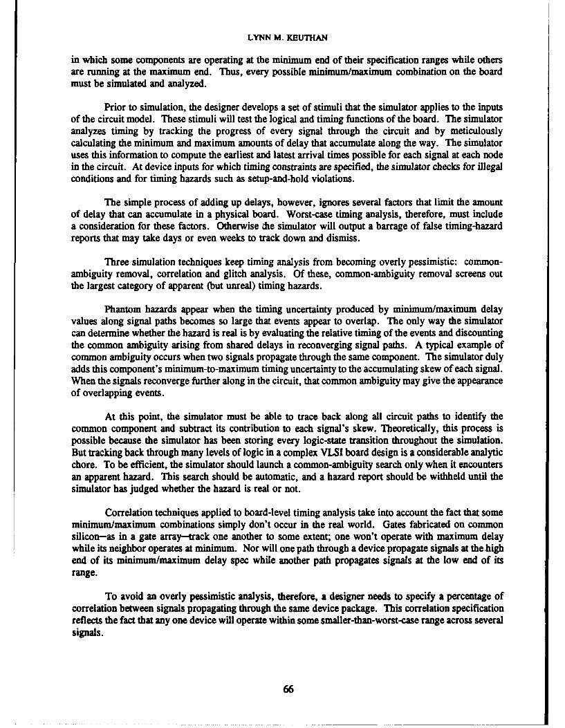
LYNN M. KEUTHAN
in which some components are operating at the minimum end of their specification ranges while othersare running at the maximum end. Thus, every possible minimum/maximum combination on the boardmust be simulated and analyzed.
Prior to simulation, the designer develops a set of stimuli that the simulator applies to the inputsof the circuit model. These stimuli will test the logical and timing functions of the board. The simulatoranalyzes timing by tracking the progress of every signal through the circuit and by meticulouslycalculating the minimum and maximum amounts of delay that accumulate along the way. The simulatoruses this information to compute the earliest and latest arrival times possible for each signal at each nodein the circuit. At device inputs for which timing constraints are specified, the simulator checks for illegalconditions and for timing hazards such as setup-and-hold violations.
The simple process of adding up delays, however, ignores several factors that limit the amountof delay that can accumulate in a physical board. Worst-case timing analysis, therefore, must includea consideration for these factors. Otherwise he simulator will output a barrage of false timing-hazardreports that may take days or even weeks to track down and dismiss.
Three simulation techniques keep timing analysis from becoming overly pessimistic: common-ambiguity removal, correlation and glitch analysis. Of these, common-ambiguity removal screens outthe largest category of apparent (but unreal) timing hazards.
Phantom hazards appear when the timing uncertainty produced by minimum/maximum delayvalues along signal paths becomes so large that events appear to overlap. The only way the simulatorcan determine whether the hazard is real is by evaluating the relative timing of the events and discountingthe common ambiguity arising from shared delays in reconverging signal paths. A typical example ofcommon ambiguity occurs when two signals propagate through the same component. The simulator dulyadds this component's minimum-to-maximum timing uncertainty to the accumulating skew of each signal.When the signals reconverge further along in the circuit, that common ambiguity may give the appearanceof overlapping events.
At this point, the simulator must be able to trace back along all circuit paths to identify thecommon component and subtract its contribution to each signal's skew. Theoretically, this process ispossible because the simulator has been storing every logic-state transition throughout the simulation.But tracking back through many levels of logic in a complex VLSI board design is a considerable analyticchore. To be efficient, the simulator should launch a common-ambiguity search only when it encountersan apparent hazard. This search should be automatic, and a hazard report should be withheld until thesimulator has judged whether the hazard is real or not.
Correlation techniques applied to board-level timing analysis take into account the fact that someminimum/maximum combinations simply don't occur in the real world. Gates fabricated on commonsilicon-as in a gate array-track one another to some extent; one won't operate with maximum delaywhile its neighbor operates at minimum. Nor will one path through a device propagate signals at the highend of its minimum/maximum delay spec while another path propagates signals at the low end of itsrange.
To avoid an overly pessimistic analysis, therefore, a designer needs to specify a percentage ofcorrelation between signals propagating through the same device package. This correlation specificationreflects the fact that any one device will operate within some smaller-than-worst-case range across severalsignals.
66
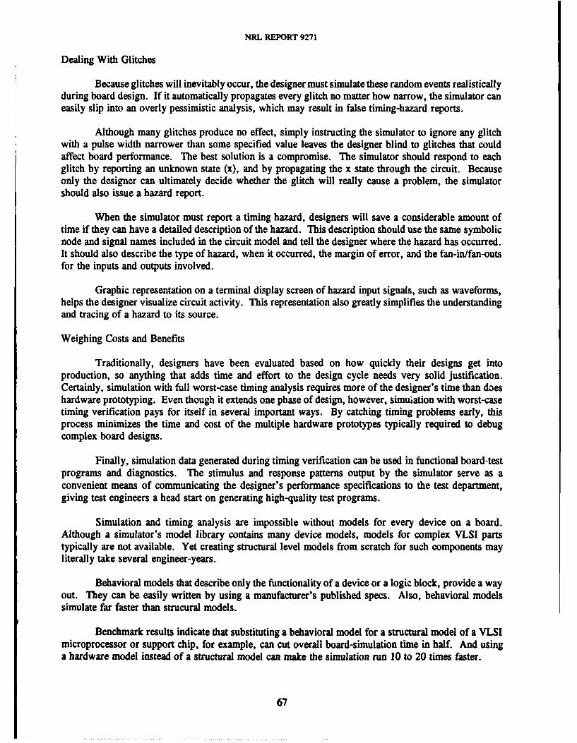
NRL REPORT 9271
Dealing With Glitches
Because glitches will inevitably occur, the designer must simulate these random events realisticallyduring board design. If it automatically propagates every glitch no matter how narrow, the simulator caneasily slip into an overly pessimistic analysis, which may result in false timing-hazard reports.
Although many glitches produce no effect, simply instructing the simulator to ignore any glitchwith a pulse width narrower than some specified value leaves the designer blind to glitches that couldaffect board performance. The best solution is a compromise. The simulator should respond to eachglitch by reporting an unknown state (x), and by propagating the x state through the circuit. Becauseonly the designer can ultimately decide whether the glitch will really cause a problem, the simulatorshould also issue a hazard report.
When the simulator must report a timing hazard, designers will save a considerable amount oftime if they can have a detailed description of the hazard. This description should use the same symbolicnode and signal names included in the circuit model and tell the designer where the hazard has occurred.It should also describe the type of hazard, when it occurred, the margin of error, and the fan-in/fan-outsfor the inputs and outputs involved.
Graphic representation on a terminal display screen of hazard input signals, such as waveforms,helps the designer visualize circuit activity. This representation also greatly simplifies the understandingand tracing of a hazard to its source.
Weighing Costs and Benefits
Traditionally, designers have been evaluated based on how quickly their designs get intoproduction, so anything that adds time and effort to the design cycle needs very solid justification.Certainly, simulation with full worst-case timing analysis requires more of the designer's time than doeshardware prototyping. Even though it extends one phase of design, however, simulation with worst-casetiming verification pays for itself in several important ways. By catching timing problems early, thisprocess minimizes the time and cost of the multiple hardware prototypes typically required to debugcomplex board designs.
Finally, simulation data generated during timing verification can be used in functional board-testprograms and diagnostics. The stimulus and response patterns output by the simulator serve as aconvenient means of communicating the designer's performance specifications to the test department,giving test engineers a head start on generating high-quality test programs.
Simulation and timing analysis are impossible without models for every device on a board.Although a simulator's model library contains many device models, models for complex VLSI partstypically are not available. Yet creating structural level models from scratch for such components mayliterally take several engineer-years.
Behavioral models that describe only the functionality of a device or a logic block, provide a wayout. They can be easily written by using a manufacturer's published specs. Also, behavioral modelssimulate far faster than strucural models.
Benchmark results indicate that substituting a behavioral model for a structural model of a VLSImicroprocessor or support chip, for example, can cut overall board-simulation time in half. And usinga hardware model instead of a structural model can make the simulation run 10 to 20 times faster.
67
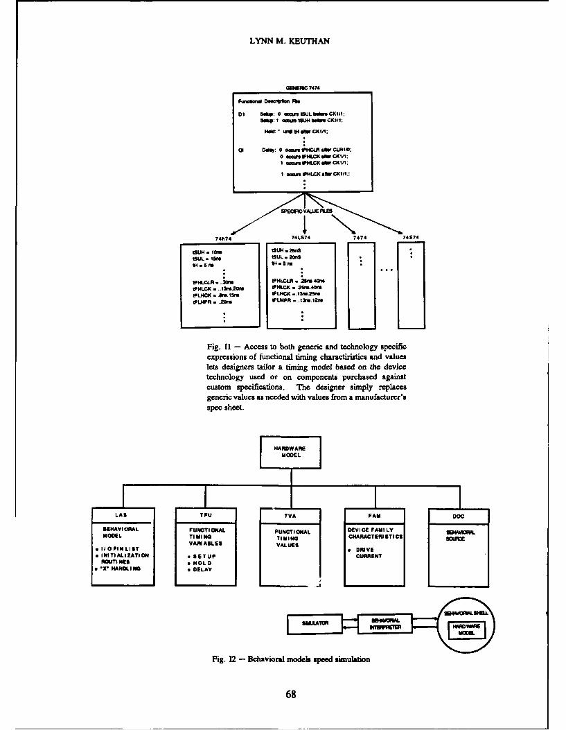
LYNN M. KEUTHAN
GEERC 7474
FWuwW Deaum Ff
01 5So 0 ocan tSUL beft.CIII;
so": wI 04"tU aoft CKI:
01 D"la: 0 oem,,;WAAR sW CLR1IO.0 aamsHLCN sCIbcci/II acews VHLCI( sAW 0(111
I acais I4LCKI( ibCII.
SPEICV.LUE FILE
707?4 74LS74 7474 74S74
ISUL . ISMtlL .*nIH .55 M I.5 no
* 3CPHLCLR - .. 21 PLL Seu 4Cm
IPHLCI( . ..131.20W IPHLCI( 25.40MlIP4CK . Amn. 15M IPL4CK( 1311625f1PLHPR . .20M IPLAPA -. 13re.12M
Fig. 11 - Access to both generic and technology specificexpressions of functional timing charactiristics and valueslets designers tailor a timing model based on the devicetechnology used or on components purchased againstcustom specifications. The designer simply replacesgeneric values as needed with values from a manufacturer'sspec sheet.
SEHVIRA FNCIOALFUNCTION4AL DEVICE FAMILY 84VW
MOE IIGTIMING CHARACTERI STI CS
Fig.LS 2- AeBaLoE$ modUES spee ViuaIn
INITALIZTIONoSETP CUR6N
NRL REPORT 9271
Two prerequisites exist for accurate worst-case timing analysis during simulations in whichbehavioral models are used. The simulator must be able to model and simulate functional timingdescriptions, and the behavioral modeling language must support propagation of x (unknown) logic statesas well as the standard 0, 1, and z (tristate) logic values through the behavioral model. Since timing haz-ards such as races or setup-and-hold violations will cause a device's output to become unknown, thesimulator's ability to propagate x states to the appropriate output pins of a behavioral model alerts adesigner to the problem.
Hardware models by themselves do not support true worst-case timing analysis because a singlephysical copy of a device cannot express the part's full range of minimum/maximum timing. Moreover,a simulator flags timing hazards by propagating x's when component outputs become unknown, but aphysical device cannot produce x's-only Is and Os.
Designers can solve the first problem by creating a software description of functional timingparameters and minimum/maximum values based on the vendor's spec sheet for the device. The simula-tor can then use this description for all timing evauations, referencing the hardware model itself only forlogical responses.
Thus, the simulator can perform minimum/maximum and full worst-case timing analysis. It canalso simulate full-board performance over a wide range of input timing parameters without requiringelaborate hardware to supply these various inputs physically to the hardware model.
To compensate for the hardware model's inability to propagate x states, the designer uses abehavioral language to write a behavioral shell. Residing in the simulator's model library along with thefunctional timing files on the device, this behavioral shell contains I/O pin list information, deviceinitialization requirements and rules for propagation of x states through the device when unknown or il-legal inputs are received.
By letting the simulator propagate x states correctly and use device responses only when thehardware model is properly initialized and synchronized, the behavioral shell ensures accurate, repeatabletiming analyses based on simulations using a hardware model.
When board designers at Teradyne's Manufacturing Systems Division began simulating theirboards by using the Lasar Version 6 simulation system, they unanimously reported that flagging timingerrors was Lasar's most valuable contribution. While timing flaws occurred less frequently than logicerrors, their tendency to make the design fail intermittently-or fail in worst-case situations-made themfar more difficult and tedious to diagnose. As a result, the engineers welcomed a tool that could automatethat chore.
A typical example of marginal performance involved a board on which pulses were created byusing the propagation delay of several components. Lasar's worst-case timing analysis revealed to twodesigners something that they had failed to consider: the pulse could be too narrow if all the componentswere operating at the fast end of their specifications.
Another designer discovered that what he had assumed to be a sound design (based on simulationusing typical timing values) proved to be marginal when subjected to a true worst-case analysis. Thedesigner found that the register's setup requirements were violated if data arrived at a register slower thanthf- typical time but still well within the allowable minimum/maximum range. The design also could nottolerate a faster-than-typical arrival of a latch-enable at the register.
69
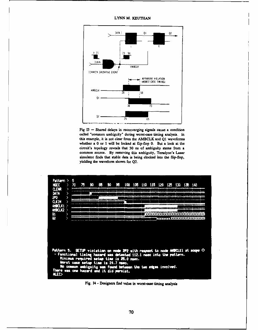
LYNN M. KEUTHAN
20 0
0 50
Fi 3-Shrddlysi eovegn inascuea odtocaled com on xnbguiy~ urig wrstcas tiinganaysi.Qithsexmleit sntcerfoNh AM BCK nIQCwvfom
w Cth rOM O r il el e flip-flop 0.EN APPtalookaOLATIO
circuit's~~~~~~~ topolog reveal tht3Tso m IIsemG ro)co Msce.B eoigthsabgiy Trdn' aa
simulator f5d0htsal at sbigcokd notefi-lp
caige 14-mo Desigrs" fdauein worst-case timing analysis.I
thsexmle t sno lerfrmth MBL adQ70veom
NRL REPORT 9271
In another case, the output of a multiplexer was to provide data to a flip-flop. But, in certaincircumstances, this multiplexer produced a glitch. Worst-case timing analysis determined that this glitchcould occur too close to the clock signal, thus violating the flip-flop's setup time requirement.
For each timing hazard, Lasar issued a hazard report that included both a detailed description anda graphic representation of the hazard. With these reports, the designers could understand and quicklycorrect the timing problems.
71