Embed Size (px)
Citation preview

Cadfil is a registered trade mark of Crescent Consultants LtdEmail: [email protected] Web: http://www.cadfil.com FEM Data Export. Page 1 of 5
Cadfil
Mandrel
Definition
Mesh (.mnd)
Winding
Program
Generated as
normal and
thickness
Angle File
(.th2) created
X R Angle t/t0 Slope
-362.00000 51.02870 85.58755 12.84866 82.38777
-361.75000 52.89932 75.89994 13.91123 82.38777
-361.50000 54.76994 69.54415 15.46581 82.38777
-361.25000 56.64056 64.90489 16.05614 82.38777
-361.00000 58.51117 61.21518 16.61810 82.38777
-360.75000 60.38179 58.12904 15.27558 82.38777
-360.50000 61.85809 56.01766 12.01105 80.21295
-360.25000 63.30739 54.00607 10.42121 80.21295
-360.00000 64.75669 52.43104 9.36588 80.21295
.......
.......
.......
EXPORTING DATA FROM CADFIL FOR FINITE
ELEMENT MODELING –(Example creating NASTRAN Bulk
Data File - bdf)

Cadfil is a registered trade mark of Crescent Consultants LtdEmail: [email protected] Web: http://www.cadfil.com FEM Data Export. Page 2 of 5
Original Mandel
used for winding
program shown
in the Cadfil
Mandrel Editor
Meshing Grading
changed to suite
Analysis mesh
requirements

Cadfil is a registered trade mark of Crescent Consultants LtdEmail: [email protected] Web: http://www.cadfil.com FEM Data Export. Page 3 of 5
Specify
circumferential
mesh grading to
complete the
surface mesh for
the analysis
Final refined
surface mesh for
export.
The Nastran export option uses
the re-graded mesh and one or
more Cadfil thickness data files
(.th2) to automatically write the
bulk data file.
Cadfil is a registered trade mark of Crescent Consultants LtdEmail: [email protected] Web: http://www.cadfil.com FEM Data Export. Page 4 of 5
BEGIN BULK
$Nastran bdf file from cadfil, www.cadfil.com
$08-APR-12 21:40:54 V12
GRID* 1 -0.365336E+03 0.000000E+00*G000001
*G000001 0.000000E+00
GRID* 2 -0.365201E+03 0.000000E+00*G000002
*G000002 0.103877E+02
GRID* 3 -0.365201E+03 0.127653E+01*G000003
*G000003 0.103090E+02
GRID* 4 -0.365201E+03 0.253370E+01*G000004
*G000004 0.100740E+02
....
....
CTRIA3 49 101 1 50 51 49
CTRIA3 50 101 1 51 52 50
CTRIA3 51 101 1 52 2 51
CQUAD4 52 102 3 2 53 54 52
CQUAD4 53 102 4 3 54 55 53
CQUAD4 54 102 5 4 55 56 54
CQUAD4 55 102 6 5 56 57 55
....
....
CORD2R* 49 0 0.00000000E+00 0.00000000E+00*CA00049
*CA00049 0.00000000E+00 -0.99991542E+00 -0.39427841E-02 0.12393921E-01*CB00049
*CB00049 0.13005954E-01 -0.30312696E+00 0.95286142E+00
CORD2R* 50 0 0.00000000E+00 0.00000000E+00*CA00050
*CA00050 0.00000000E+00 -0.99991542E+00 -0.23898449E-02 0.12784501E-01*CB00050
*CB00050 0.13005953E-01 -0.18373390E+00 0.98288997E+00
CORD2R* 51 0 0.00000000E+00 0.00000000E+00*CA00051
*CA00051 0.00000000E+00 -0.99991542E+00 -0.80065724E-03 0.12981285E-01*CB00051
*CB00051 0.13005953E-01 -0.61555722E-01 0.99801891E+00
....
....
PCOMP 106 0.000 +P100006
+P100006 1 0.749 64.588 YES 1 0.749 -64.588 YES
PCOMP 107 0.000 +P100007
+P100007 1 0.393 50.014 YES 1 0.393 -50.014 YES
PCOMP 108 0.000 +P100008
+P100008 1 0.304 41.496 YES 1 0.304 -41.496 YES
....
....
ENDDATA
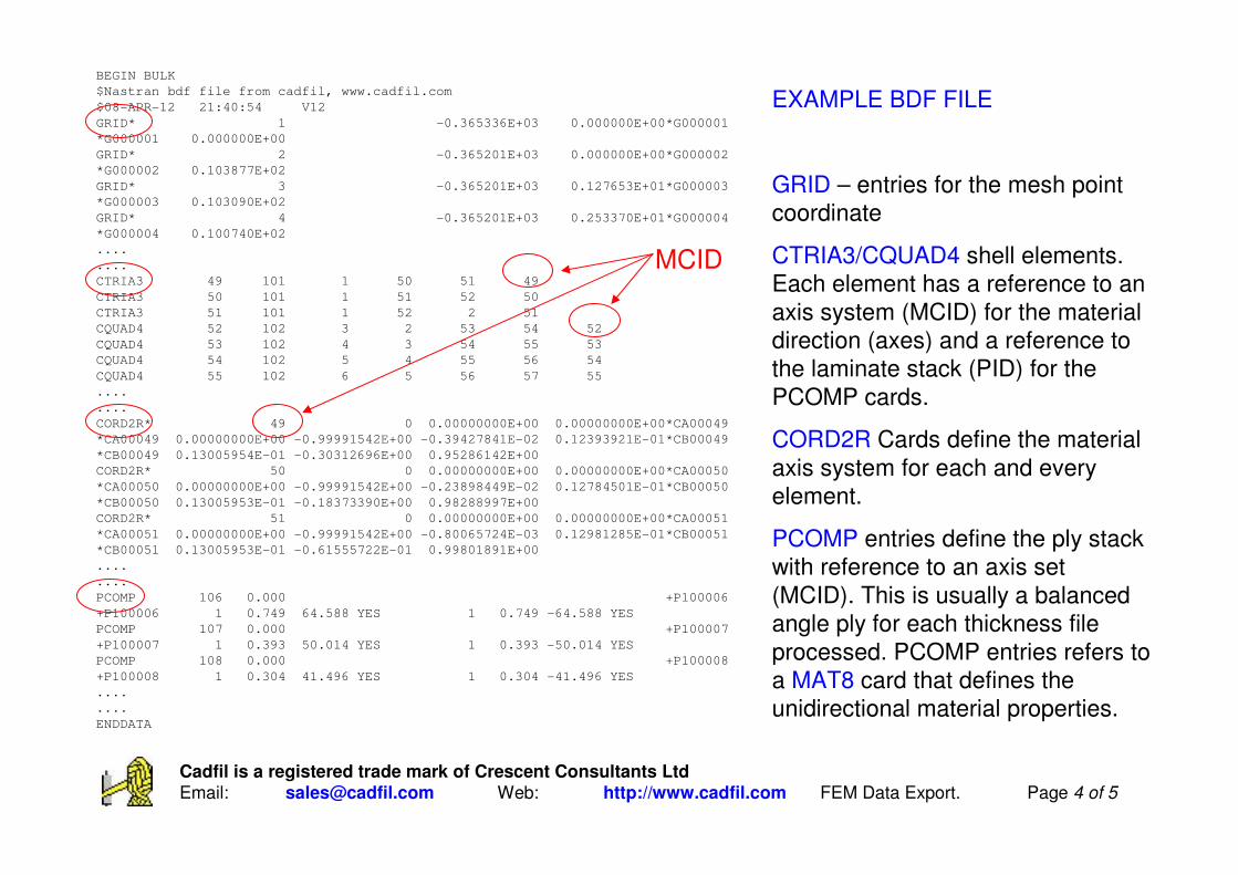
EXAMPLE BDF FILE
GRID – entries for the mesh point
coordinate
CTRIA3/CQUAD4 shell elements.
Each element has a reference to an
axis system (MCID) for the material
direction (axes) and a reference to
the laminate stack (PID) for the
PCOMP cards.
CORD2R Cards define the material
axis system for each and every
element.
PCOMP entries define the ply stack
with reference to an axis set
(MCID). This is usually a balanced
angle ply for each thickness file
processed. PCOMP entries refers to
a MAT8 card that defines the
unidirectional material properties.
MCID

Cadfil is a registered trade mark of Crescent Consultants LtdEmail: [email protected] Web: http://www.cadfil.com FEM Data Export. Page 5 of 5
These Views are taken from the MSC Pre-Processor software after importing a Cadfil
Bulk data file (.bdf). The View top left shows the full shell mesh. The View top middle
shows the principal material orientations for the angle-plies. View top right shows the
banded PCOMP entries. As can be see the PCOMP entries are in constant in bands
around the mandrel as the winding angle and thickness are a constant around the band,
only the ply orientation changes. The grey zone at the mandrel has been assigned a
default (dummy) property because this area of the mandrel was not over-wound in
CADFIL in this example.