Embed Size (px)
Citation preview
2010 Version 1
p r e c a s t @ f p m cc a n n . co. u k w w w. f p m cc a n n . co. u k
FP McCann
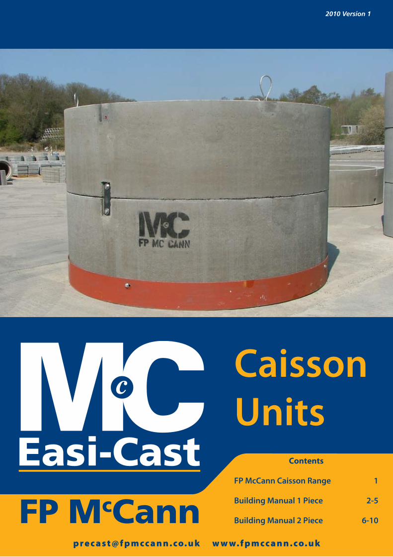
CaissonUnits
Contents
FP McCann Caisson Range 1
Building Manual 1 Piece 2-5
Building Manual 2 Piece 6-10
1 www.fpmccann.co.uk [email protected]
FP M cCann Precast Concrete Systems P1
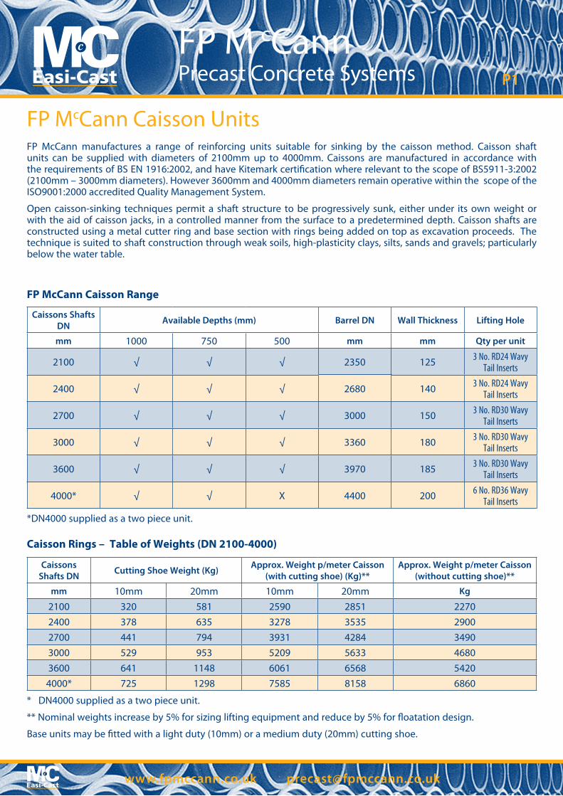
FP McCann Caisson Range
FP McCann Caisson Units
Caissons Shafts DN Available Depths (mm) Barrel DN Wall Thickness Lifting Hole
mm 1000 750 500 mm mm Qty per unit
2100 √ √ √ 2350 125 3 No. RD24 Wavy Tail Inserts
2400 √ √ √ 2680 140 3 No. RD24 Wavy Tail Inserts
2700 √ √ √ 3000 150 3 No. RD30 Wavy Tail Inserts
3000 √ √ √ 3360 180 3 No. RD30 Wavy Tail Inserts
3600 √ √ √ 3970 185 3 No. RD30 Wavy Tail Inserts
4000* √ √ X 4400 200 6 No. RD36 Wavy Tail Inserts
*DN4000 supplied as a two piece unit.
Caisson Rings – Table of Weights (DN 2100-4000)
Caissons Shafts DN Cutting Shoe Weight (Kg) Approx. Weight p/meter Caisson
(with cutting shoe) (Kg)**Approx. Weight p/meter Caisson
(without cutting shoe)**
mm 10mm 20mm 10mm 20mm Kg
2100 320 581 2590 2851 22702400 378 635 3278 3535 29002700 441 794 3931 4284 34903000 529 953 5209 5633 46803600 641 1148 6061 6568 54204000* 725 1298 7585 8158 6860
* DN4000 supplied as a two piece unit.
** Nominal weights increase by 5% for sizing lifting equipment and reduce by 5% for �oatation design.
Base units may be �tted with a light duty (10mm) or a medium duty (20mm) cutting shoe.
FP McCann manufactures a range of reinforcing units suitable for sinking by the caisson method. Caisson shaft units can be supplied with diameters of 2100mm up to 4000mm. Caissons are manufactured in accordance with the requirements of BS EN 1916:2002, and have Kitemark certi�cation where relevant to the scope of BS5911-3:2002 (2100mm – 3000mm diameters). However 3600mm and 4000mm diameters remain operative within the scope of the ISO9001:2000 accredited Quality Management System.
Open caisson-sinking techniques permit a shaft structure to be progressively sunk, either under its own weight or with the aid of caisson jacks, in a controlled manner from the surface to a predetermined depth. Caisson shafts are constructed using a metal cutter ring and base section with rings being added on top as excavation proceeds. The technique is suited to shaft construction through weak soils, high-plasticity clays, silts, sands and gravels; particularly below the water table.
2 www.fpmccann.co.uk [email protected]
FP McCann Precast Concrete Systems P2
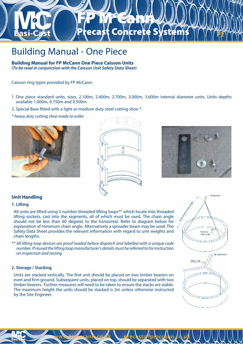
Building Manual - One PieceBuilding Manual for FP McCann One Piece Caisson Units(To be read in conjunction with the Caisson Unit Safety Data Sheet)
Caisson ring types provided by FP McCann:
1. One piece standard units, sizes, 2.100m, 2.400m, 2.700m, 3.000m, 3.600m internal diameter units. Units depths available 1.000m, 0.750m and 0.500m.
2. Special Base fitted with a light or medium duty steel cutting shoe *.
* heavy duty cutting shoe made to order
Unit Handling1. Lifting
All units are lifted using 3 number threaded lifting loops** which locate into threaded lifting sockets, cast into the segments, all of which must be used. The chain angle should not be less than 60 degrees to the horizontal. Refer to diagram below for explanation of minimum chain angle. Alternatively a spreader beam may be used. The Safety Data Sheet provides the relevant information with regard to unit weights and chain lengths.
** All lifting loop devices are proof loaded before dispatch and labelled with a unique code number. If reused the lifting loop manufacturer’s details must be referred to for instruction on inspection and testing.
2. Storage / Stacking
Units are stacked vertically. The first unit should be placed on two timber bearers on even and firm ground. Subsequent units, placed on top, should be separated with two timber bearers. Further measures will need to be taken to ensure the stacks are stable. The maximum height the units should be stacked is 2m unless otherwise instructed by the Site Engineer.
3 www.fpmccann.co.uk [email protected]
FP McCann Precast Concrete Systems P3
Building Manual - One PieceShaft design
The units are designed by FP McCann for handling and installation only. The overall shaft design should be undertaken by the Scheme Engineer. For advice contact FP McCann Technical Department.
Joint seal
All rings have a tongue and groove circle joint which has been designed to incorporate a bitumen rubber compressible. The seal should be fitted on site just prior to installation.
Building Sequence
The sequence of installation described in this document is indicative only and the exact method of installation is the responsibility of the Contractor. Health and Safety measures that apply specifically to the caisson units and their fittings are indicated, other measures that apply to the shaft construction e.g. temporary guard rails to the top of the shaft, are the responsibility of the Contractor.
Building Sequence
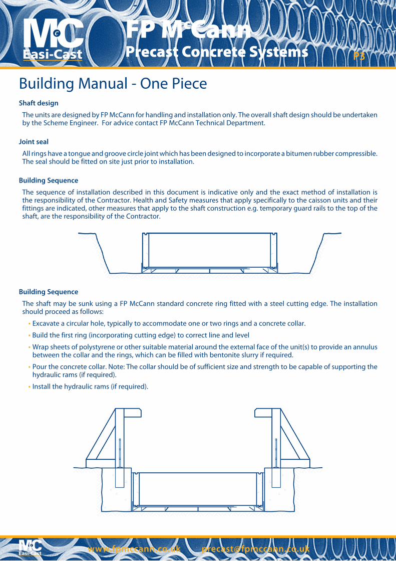
The shaft may be sunk using a FP McCann standard concrete ring fitted with a steel cutting edge. The installation should proceed as follows:
• Excavate a circular hole, typically to accommodate one or two rings and a concrete collar.
• Build the first ring (incorporating cutting edge) to correct line and level
• Wrap sheets of polystyrene or other suitable material around the external face of the unit(s) to provide an annulus between the collar and the rings, which can be filled with bentonite slurry if required.
• Pour the concrete collar. Note: The collar should be of sufficient size and strength to be capable of supporting the hydraulic rams (if required).
• Install the hydraulic rams (if required).
4 www.fpmccann.co.uk [email protected]
FP McCann Precast Concrete Systems P4
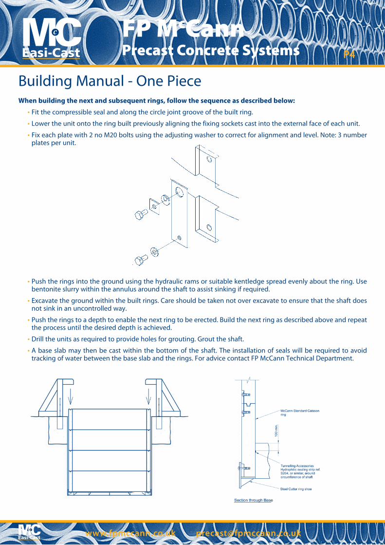
When building the next and subsequent rings, follow the sequence as described below:
• Fit the compressible seal and along the circle joint groove of the built ring.
• Lower the unit onto the ring built previously aligning the fixing sockets cast into the external face of each unit.
• Fix each plate with 2 no M20 bolts using the adjusting washer to correct for alignment and level. Note: 3 number plates per unit.
Building Manual - One Piece
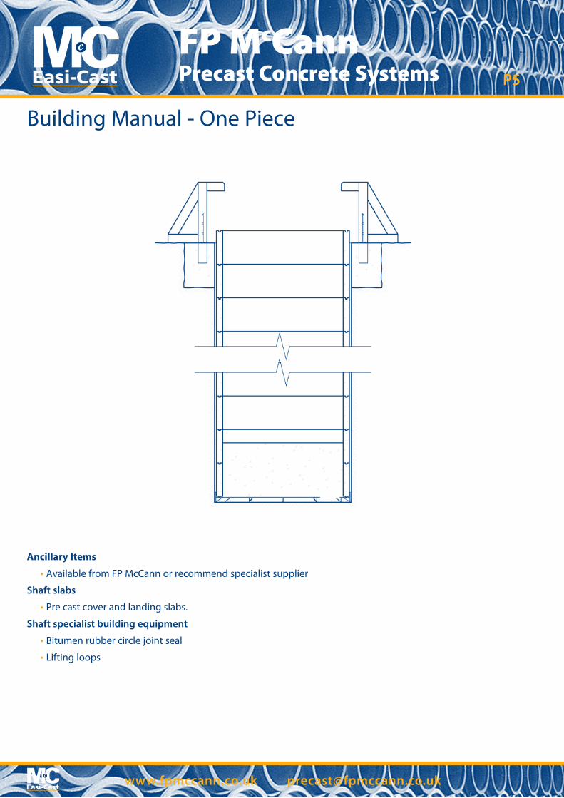
• Push the rings into the ground using the hydraulic rams or suitable kentledge spread evenly about the ring. Use bentonite slurry within the annulus around the shaft to assist sinking if required.
• Excavate the ground within the built rings. Care should be taken not over excavate to ensure that the shaft does not sink in an uncontrolled way.
• Push the rings to a depth to enable the next ring to be erected. Build the next ring as described above and repeat the process until the desired depth is achieved.
• Drill the units as required to provide holes for grouting. Grout the shaft.
• A base slab may then be cast within the bottom of the shaft. The installation of seals will be required to avoid tracking of water between the base slab and the rings. For advice contact FP McCann Technical Department.
5 www.fpmccann.co.uk [email protected]
FP McCann Precast Concrete Systems P5
Building Manual - One Piece
Ancillary Items
• Available from FP McCann or recommend specialist supplier
Shaft slabs
• Pre cast cover and landing slabs.
Shaft specialist building equipment
• Bitumen rubber circle joint seal
• Lifting loops
6 www.fpmccann.co.uk [email protected]
FP McCann Precast Concrete Systems P6
Building Manual - Two PieceBuilding Manual for FP McCann Two Piece Caisson Units(To be read in conjunction with the Caisson Unit Safety Data Sheet)
Caisson ring types provided by FP McCann:
1. Two piece standard unit size 4.000m internal diameter units. Unit depths available 1.000m and 0.750m.
2. Special bases fitted with a light or medium duty steel cutting shoe *.
* heavy duty cutting shoe made to order
Unit Handling
1. Lifting
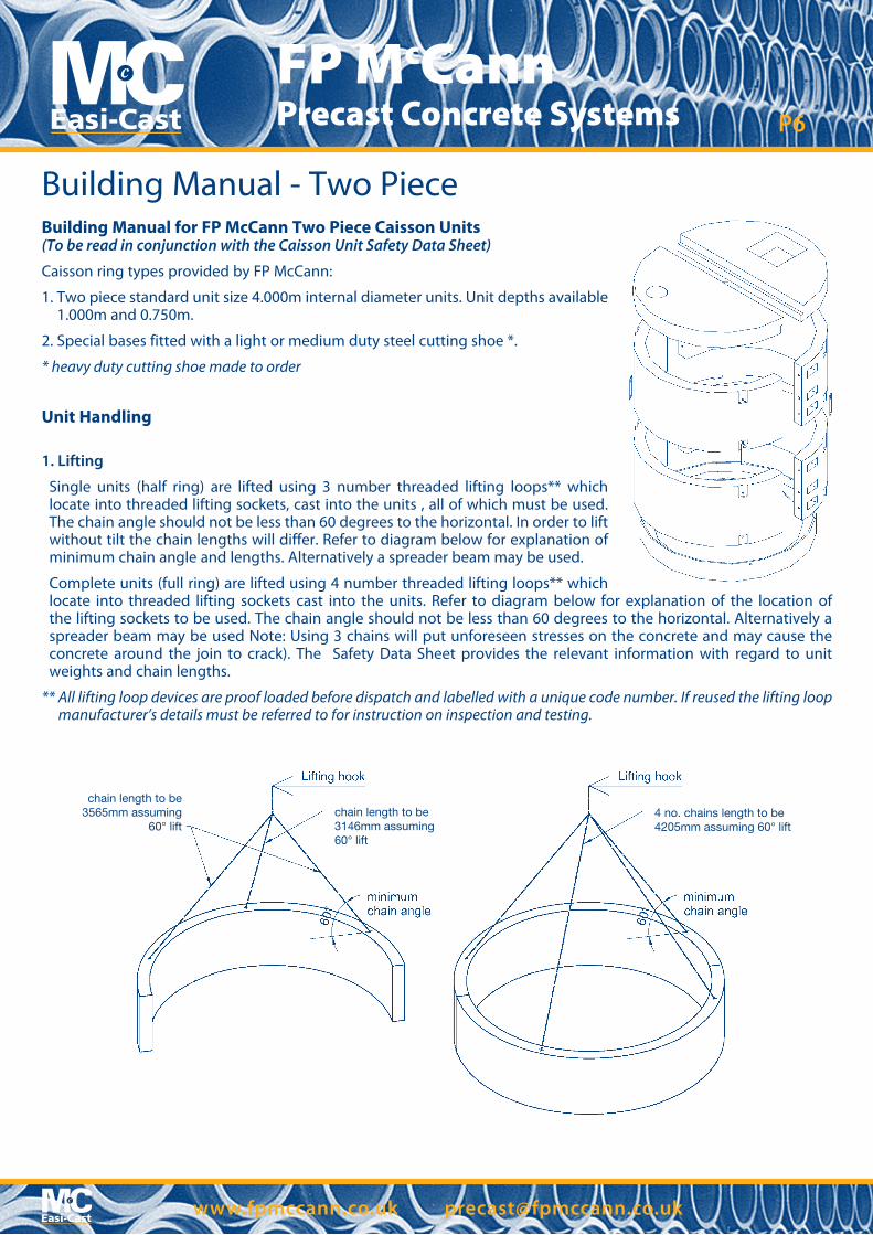
Single units (half ring) are lifted using 3 number threaded lifting loops** which locate into threaded lifting sockets, cast into the units , all of which must be used. The chain angle should not be less than 60 degrees to the horizontal. In order to lift without tilt the chain lengths will differ. Refer to diagram below for explanation of minimum chain angle and lengths. Alternatively a spreader beam may be used.
Complete units (full ring) are lifted using 4 number threaded lifting loops** which locate into threaded lifting sockets cast into the units. Refer to diagram below for explanation of the location of the lifting sockets to be used. The chain angle should not be less than 60 degrees to the horizontal. Alternatively a spreader beam may be used Note: Using 3 chains will put unforeseen stresses on the concrete and may cause the concrete around the join to crack). The Safety Data Sheet provides the relevant information with regard to unit weights and chain lengths.
** All lifting loop devices are proof loaded before dispatch and labelled with a unique code number. If reused the lifting loop manufacturer’s details must be referred to for instruction on inspection and testing.
chain length to be3565mm assuming
60° liftchain length to be3146mm assuming 60° lift
4 no. chains length to be4205mm assuming 60° lift
7 www.fpmccann.co.uk [email protected]
FP McCann Precast Concrete Systems P7
2. Storage / Stacking
Units are stacked vertically. The first unit should be placed on two timber bearers on even and firm ground. Subsequent units, placed on top, should be separated with two timber bearers. Further measures will need to be taken to ensure the stacks are stable. The maximum height the units should be stacked is 2m unless otherwise instructed by the Site Engineer.
Shaft design
The units are designed by FP McCann for handling and installation only. The overall shaft design should be undertaken by the Scheme Engineer. For advice contact FP McCann Technical Department.
Joint seal
All rings have a tongue and groove circle joint which has been designed to incorporate a bitumen rubber compressible seal. The seal should be fitted on site just prior to installation.
Building Sequence
The sequence of installation described in this document is indicative only and the exact method of installation is the responsibility of the Contractor. Health and Safety measures that apply specifically to the caisson units and their fittings are indicated, other measures that apply to the shaft construction e.g. temporary guard rails to the top of the shaft, are the responsibility of the Contractor.
Building Manual - Two Piece
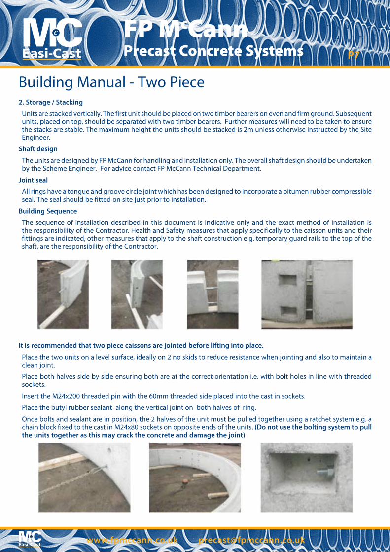
It is recommended that two piece caissons are jointed before lifting into place.
Place the two units on a level surface, ideally on 2 no skids to reduce resistance when jointing and also to maintain a clean joint.
Place both halves side by side ensuring both are at the correct orientation i.e. with bolt holes in line with threaded sockets.
Insert the M24x200 threaded pin with the 60mm threaded side placed into the cast in sockets.
Place the butyl rubber sealant along the vertical joint on both halves of ring.
Once bolts and sealant are in position, the 2 halves of the unit must be pulled together using a ratchet system e.g. a chain block fixed to the cast in M24x80 sockets on opposite ends of the units. (Do not use the bolting system to pull the units together as this may crack the concrete and damage the joint)
8 www.fpmccann.co.uk [email protected]
FP McCann Precast Concrete Systems P8
Building Manual - Two Piece
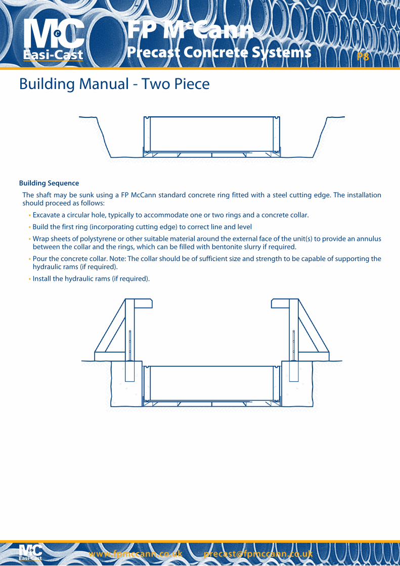
Building Sequence
The shaft may be sunk using a FP McCann standard concrete ring fitted with a steel cutting edge. The installation should proceed as follows:
• Excavate a circular hole, typically to accommodate one or two rings and a concrete collar.
• Build the first ring (incorporating cutting edge) to correct line and level
• Wrap sheets of polystyrene or other suitable material around the external face of the unit(s) to provide an annulus between the collar and the rings, which can be filled with bentonite slurry if required.
• Pour the concrete collar. Note: The collar should be of sufficient size and strength to be capable of supporting the hydraulic rams (if required).
• Install the hydraulic rams (if required).
9 www.fpmccann.co.uk [email protected]
FP McCann Precast Concrete Systems P9
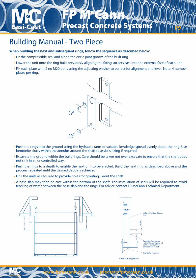
When building the next and subsequent rings, follow the sequence as described below:
• Fit the compressible seal and along the circle joint groove of the built ring.
• Lower the unit onto the ring built previously aligning the fixing sockets cast into the external face of each unit.
• Fix each plate with 2 no M20 bolts using the adjusting washer to correct for alignment and level. Note: 4 number plates per ring.
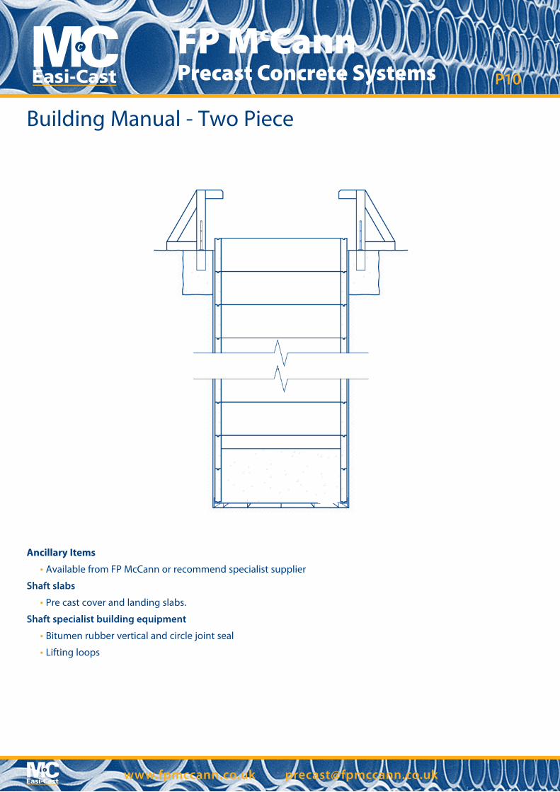
• Push the rings into the ground using the hydraulic rams or suitable kentledge spread evenly about the ring. Use bentonite slurry within the annulus around the shaft to assist sinking if required.
• Excavate the ground within the built rings. Care should be taken not over excavate to ensure that the shaft does not sink in an uncontrolled way.
• Push the rings to a depth to enable the next unit to be erected. Build the next ring as described above and the process repeated until the desired depth is achieved.
• Drill the units as required to provide holes for grouting. Grout the shaft.
• A base slab may then be cast within the bottom of the shaft. The installation of seals will be required to avoid tracking of water between the base slab and the rings. For advice contact FP McCann Technical Department.
Building Manual - Two Piece
10 www.fpmccann.co.uk [email protected]
FP McCann Precast Concrete Systems P10
Ancillary Items
• Available from FP McCann or recommend specialist supplier
Shaft slabs
• Pre cast cover and landing slabs.
Shaft specialist building equipment
• Bitumen rubber vertical and circle joint seal
• Lifting loops
Building Manual - Two Piece

Knockloughrim Quarry3 Drumard Road
MagherafeltBT45 8QA
Tel: 028 7964 2558Fax: 028 7964 4224
EllistownWhitehill RoadLeicestershire
EnglandLE67 1ET
Tel: 01530 240000Fax: 01530 240013
AlnwickLittle Houghton
NorthumberlandEnglandNE66 3JX
Tel: 01665 577653Fax: 01665 577711
TelfordDoseley Telford
ShropshireTF4 3BX
Tel: 01952 630300Fax: 01952 501537
CadebyBrasscote Lane
Cadeby, NuneatonWarks
CV13 0BB
Tel: 01455 290780Fax: 01455 292189
Precast Office Locations
Precast Head Office