Embed Size (px)
Citation preview
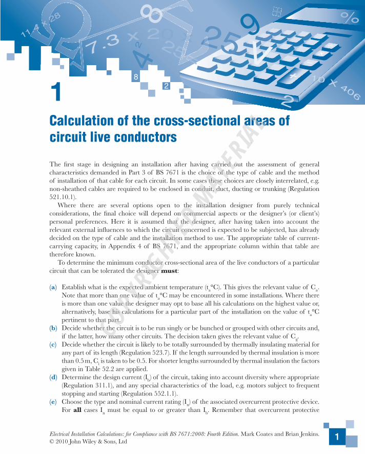
Calculation of the cross-sectional areas of circuit live conductors
1
9
2
8
=
++
47.3 x 20 x 25 V2
8
%
2 2511.4 x 28
10 X 406
1 2
1Calculation of the cross-sectional areas of circuit live conductors
The first stage in designing an installation after having carried out the assessment of general characteristics demanded in Part 3 of BS 7671 is the choice of the type of cable and the method of installation of that cable for each circuit. In some cases these choices are closely interrelated, e.g. non-sheathed cables are required to be enclosed in conduit, duct, ducting or trunking (Regulation 521.10.1).
Where there are several options open to the installation designer from purely technical considerations, the final choice will depend on commercial aspects or the designer’s (or client’s) personal preferences. Here it is assumed that the designer, after having taken into account the relevant external influences to which the circuit concerned is expected to be subjected, has already decided on the type of cable and the installation method to use. The appropriate table of current-carrying capacity, in Appendix 4 of BS 7671, and the appropriate column within that table are therefore known.
To determine the minimum conductor cross-sectional area of the live conductors of a particular circuit that can be tolerated the designer must:
(a) Establish what is the expected ambient temperature (ta°C). This gives the relevant value of Ca. Note that more than one value of ta°C may be encountered in some installations. Where there is more than one value the designer may opt to base all his calculations on the highest value or, alternatively, base his calculations for a particular part of the installation on the value of ta°C pertinent to that part.
(b) Decide whether the circuit is to be run singly or be bunched or grouped with other circuits and, if the latter, how many other circuits. The decision taken gives the relevant value of Cg.
(c) Decide whether the circuit is likely to be totally surrounded by thermally insulating material for any part of its length (Regulation 523.7). If the length surrounded by thermal insulation is more than 0.5 m, Ci is taken to be 0.5. For shorter lengths surrounded by thermal insulation the factors given in Table 52.2 are applied.
(d) Determine the design current (Ib) of the circuit, taking into account diversity where appropriate (Regulation 311.1), and any special characteristics of the load, e.g. motors subject to frequent stopping and starting (Regulation 552.1.1).
(e) Choose the type and nominal current rating (In) of the associated overcurrent protective device. For all cases In must be equal to or greater than Ib. Remember that overcurrent protective
Electrical Installation Calculations: for Compliance with BS 7671:2008: Fourth Edition. Mark Coates and Brian Jenkins. © 2010 John Wiley & Sons, Ltd
COPYRIG
HTED M
ATERIAL
Electrical Installations Calculations
2
devices must comply with Chapter 43 of BS 7671 as regards their breaking capacity, but for the present let it be assumed the chosen devices do so comply.
(f) Establish whether it is intended the overcurrent protective device is to give:(i) overload protection only, or(ii) short circuit protection only, or(iii) overload and short circuit protection.
The intended function of the overcurrent protective device not only determines whether Ib or In is used as the basis for calculating the minimum cross-sectional area of the live conductors, but also influences the value of Ca that is to be used in the calculations.
(g) Establish the maximum voltage drop that can be tolerated.(h) Estimate the route length of the circuit.
If the cable circuit is to be buried direct in the ground or in buried ducts there are further factors the designer must consider. These factors include:
(a) The thermal resistivity of the ground. The tabulated ratings given for buried cables in BS 7671 are for cables buried ‘in or around buildings’. These ratings assume that the cables are buried in dry made-up ground that is likely to contain rubble, clinker and similar materials having poor thermal properties. Because of this the ratings are based on a soil thermal resistivity of 2.5 K.m/W. This is considerably higher than the accepted value of 1.2 K.m/W for the natural soil in the UK, see BS IEC 60827–3-1. Tabulated ratings for buried cables based on a thermal resistivity of 1.2 K.m/W are given in ERA Reports 69–30 Parts III and IV as well as being provided by some UK cable suppliers. The thermal properties of the soil determine the value of Cs selected from Table 4B3 of BS 7671.
(b) The depth of burial of the cables or ducts. The deeper a circuit is buried the lower its current rating. The tabulated ratings given in BS 7671 are for a depth of burial of 0.8 m and no factors are given for different depths of burial. Derating factors for different depths, Cb, may be obtained from the cable supplier or taken from ERA Report 69–30 Part III or IV. However the ratings in many manufacturers’ data and in the ERA reports are for a depth of burial of 0.5 m. Thus the factors for different depths of burial would have to be manipulated before being applied to ratings based on a depth of 0.8 m.
(c) Ground ambient temperature. The tabulated ratings for buried cables given in BS 7671 are based on a ground ambient temperature of 20°C. This is applicable under buildings, but the designer should be aware that the accepted ground ambient temperature for general conditions in the UK is 15°C, see BS IEC 60287–3-1.
(d) Overload protection of buried cables. The requirement of Regulation 433.1.1 (iii) is applicable to circuits where the tabulated current ratings are based on an ambient temperature of 30°C. To achieve overload protection for a buried cable circuit the 1.45 factor given in Regulation 433.1.1 (iii) should be reduced to 1.3. In BS 7671 this is achieved by applying a factor of 0.9 to the current-carrying capacity, Iz, as required by Regulation 433.1.4. As an alternative the overload protective device should be selected such that I2 < 1.3Iz.
It cannot be emphasized too strongly that unless all the foregoing items are available it is not possible to design any circuit.
Calculation of the cross-sectional areas of circuit live conductors
3
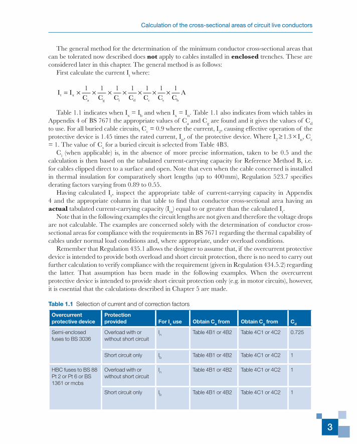
The general method for the determination of the minimum conductor cross-sectional areas that can be tolerated now described does not apply to cables installed in enclosed trenches. These are considered later in this chapter. The general method is as follows:
First calculate the current It where:
I IC C C C C C C
At xa g i d c s b
= × × × × × × ×1 1 1 1 1 1 1
Table 1.1 indicates when Ix = Ib and when Ix = In. Table 1.1 also indicates from which tables in Appendix 4 of BS 7671 the appropriate values of Ca and Cg are found and it gives the values of Cd to use. For all buried cable circuits, Cc = 0.9 where the current, I2, causing effective operation of the protective device is 1.45 times the rated current, In, of the protective device. Where I2 ≥ 1.3 × In, Cc = 1. The value of Cs for a buried circuit is selected from Table 4B3.
Ci (when applicable) is, in the absence of more precise information, taken to be 0.5 and the calculation is then based on the tabulated current-carrying capacity for Reference Method B, i.e. for cables clipped direct to a surface and open. Note that even when the cable concerned is installed in thermal insulation for comparatively short lengths (up to 400 mm), Regulation 523.7 specifies derating factors varying from 0.89 to 0.55.
Having calculated It, inspect the appropriate table of current-carrying capacity in Appendix 4 and the appropriate column in that table to find that conductor cross-sectional area having an actual tabulated current-carrying capacity (Ita) equal to or greater than the calculated It.
Note that in the following examples the circuit lengths are not given and therefore the voltage drops are not calculable. The examples are concerned solely with the determination of conductor cross-sectional areas for compliance with the requirements in BS 7671 regarding the thermal capability of cables under normal load conditions and, where appropriate, under overload conditions.
Remember that Regulation 435.1 allows the designer to assume that, if the overcurrent protective device is intended to provide both overload and short circuit protection, there is no need to carry out further calculation to verify compliance with the requirement (given in Regulation 434.5.2) regarding the latter. That assumption has been made in the following examples. When the overcurrent protective device is intended to provide short circuit protection only (e.g. in motor circuits), however, it is essential that the calculations described in Chapter 5 are made.
Table 1.1 Selection of current and of correction factors
Overcurrent protective device
Protection provided For Ix use Obtain Ca from Obtain Cg from Cd
Semi-enclosed fuses to BS 3036
Overload with or without short circuit
In Table 4B1 or 4B2 Table 4C1 or 4C2 0.725
Short circuit only Ib Table 4B1 or 4B2 Table 4C1 or 4C2 1
HBC fuses to BS 88 Pt 2 or Pt 6 or BS 1361 or mcbs
Overload with or without short circuit
In Table 4B1 or 4B2 Table 4C1 or 4C2 1
Short circuit only Ib Table 4B1 or 4B2 Table 4C1 or 4C2 1
Electrical Installations Calculations
4
Overcurrent protective devices are also frequently intended to provide automatic disconnection of the supply in the event of an earth fault (i.e. to provide protection against indirect contact) and the calculations that are then necessary are described in Chapter 3.
In practice, particularly with single-phase circuits which are not bunched, it will be found that voltage drop under normal load conditions determines the cross-sectional area of the circuit live conductors that can be used. For this reason Chapter 2 deals with voltage drop calculations as these are sensibly the next stage in circuit design.
General circuits
Example 1.1
A single-phase circuit is to be wired in insulated and sheathed single-core cables having copper conductors and thermoplastic insulation, 70°C. The cables are to be installed in free air, horizontal, flat spaced on cable supports (Reference Method E).
If Ib = 135 A, ta = 50°C and overload and short circuit protection is to be provided by a BS 88–2.2 ‘gG’ fuse, what is the minimum current rating for that fuse and the minimum cross-sectional area of the cable conductors that can be used?
Answer
Because In ≥ Ib, select In from the standard ratings of BS 88–2.2. Therefore In = 160 A.From Table 4B1, Ca = 0.71. As there is no grouping, Cg = 1. Also Ci = 1 and Cd = 1.Thus:
I A At = × =1601
0 71225 4
..
From Table 4D1A Column 11 it is found that 50 mm2 is inadequate because Ita would be only 219 A. The minimum conductor cross-sectional area that can be used is 70 mm2 having Ita = 281 A.
Example 1.2
A d.c. circuit has a design current of 28 A. It is to be wired in a two-core cable having 90°C thermosetting insulation and copper conductors. It is to be installed in trunking with five other similar circuits.
If ta = 40°C and the circuit is to be protected by a 45 A HBC fuse to BS 1361 against short circuit faults only, what is the minimum conductor cross-sectional area that can be used?
Answer
From Table 4C1, Cg = 0.57 (there being a total of six circuits).From Table 4B1, Ca = 0.91. Also Ci = 1 and Cd = 1.Thus:
I A At = × × =281
0 911
0 5754
. .
Calculation of the cross-sectional areas of circuit live conductors
5
From Table 4E2A Column 2 the minimum conductor cross-sectional area that can be used is found to be 10 mm2 having Ita = 57 A.
Note that in this example the Ib of 28 A is used to determine It because only short circuit protection is intended and that it is still necessary to check that the 10 mm2 conductors will comply with Regulation 434.5.2, using the procedure described in Chapter 5.
Example 1.3
A single-phase circuit has Ib = 17 A and is to be wired in flat two-core (with cpc) 70º C thermoplastic insulated and sheathed cable having copper conductors, grouped with four other similar cables, all clipped direct.
If ta = 45°C and the circuit is to be protected against both overload and short circuit by a semi-enclosed fuse to BS 3036, what should be the nominal current rating of that fuse and the minimum cross-sectional area of cable conductor?
Answer
Because In ≥ Ib select from the standard ratings for BS 3036 fuses, In = 20 A.From Table 4C1, Cg = 0.60 (there being a total of five circuits).From Table 4B1, Ca = 0.79. Also Ci = 1 and Cd = 0.725.Thus:
I A At = × × × =201
0 791
0 601
0 72558 2
. . ..
From Table 4D5A Column 7 it is found that the minimum conductor cross-sectional area that can be used is 10 mm2 having Ita = 64 A.
Circuits in thermally insulating walls
Example 1.4
Five similar three-phase circuits each having Ib = 30 A are to be wired in single-core 70°C thermoplastic insulated non-sheathed cables having copper conductors. The circuits are installed in trunking in a thermally insulating wall, the trunking being in contact with a thermally conductive surface on one side (Reference Method A).
If the circuits are protected against both overload and short circuit by 32 A BS 88–2.2 ‘gG’ fuses and ta = 45°C, what is the minimum conductor cross-sectional area that can be used?
Answer
From Table 4C1, Cg = 0.60. From Table 4B1, Ca = 0.79. Also Ci = 1 and Cd = 1.Thus:
I A At = × × =321
0 791
0 6067 5
. ..
Electrical Installations Calculations
6
From Table 4D1A Column 3 it is found that the minimum conductor cross-sectional area that can be used is 25 mm2 having Ita = 73 A.
Circuits totally surrounded by thermally insulating material
Example 1.5
Six similar single-phase circuits each having Ib = 8 A are to be wired in single-core 70°C thermoplastic insulated non-sheathed cables having copper conductors. The cables are enclosed in conduit totally surrounded by thermally insulating material.
If the ambient temperature is expected to be 45°C and each circuit is protected by a 10 A miniature circuit breaker against both overload and short circuit, what is the minimum cross-sectional area of conductor that can be used?
Answer
From Table 4C1, Cg = 0.57. From Table 4B1, Ca = 0.79.The relevant table of current-carrying capacity is Table 4D1A. Column 2 must not be used
because it relates to Reference Method A where the conduit enclosing the cable(s) is in contact with a thermally conductive surface on one side. In this example the conduit is totally surrounded by thermally insulating material: Regulation 523.7 indicates that in such cases the factor Ci (= 0.5) has to be related to the current-carrying capacities for cables clipped direct (Reference Method C). Thus:
I A 44.4At = × × × =101
0 791
0 571
0 5. . .
From Column 6 of Table 4D1A it is found that the minimum conductor cross-sectional area that can be used is 6 mm2 having Ita = 47 A.
Note that exactly the same procedure must be used if the cable(s) concerned are not in conduit but still totally surrounded by thermally insulating material. Regulation 523.7, as already indicated, gives derating or correction factors for cables installed in thermal insulation for comparatively short lengths, i.e. up to 0.4 m.
Circuits in varying external influences and installation conditions
In practice, the problem is frequently encountered that a circuit is so run that the relevant values of Ca and/or Cg are not constant or applicable over the whole circuit length. In such cases, provided that the Reference Method does remain the same, the quickest way of determining the minimum conductor cross-sectional area that can be used is to calculate the product CaCg for each section of the circuit and then to use the lowest such product in the equation for determining It.
Example 1.6
A single-phase circuit is to be wired in single-core 70°C thermoplastic insulated non-sheathed cables having copper conductors and protected against both overload and short circuit by a 25 A BS 88–2.2
Calculation of the cross-sectional areas of circuit live conductors
7
‘gG’ fuse. For approximately the first third of its route it is run in trunking with six other similar circuits in an ambient temperature of 30°C. For the remaining two-thirds of its route it is run in conduit on a wall but with no other circuits and where the ambient temperature is 50°C.
Determine the minimum conductor cross-sectional area that can be used.
Answer
The method of installation is Reference Method B throughout, so proceed as follows.For the first third of the route: Ca = 1 and, from Table 4C1, Cg = 0.54. Thus:
CaCg = 0.54.
For the remaining two-thirds of the route: from Table 4B1, Ca = 0.71 but Cg = 1.Thus:
CaCg = 0.71
The more onerous section of the route is therefore the first third, i.e. in the trunking and
I A At = =25
0 5446 3
..
From Table 4D1A Column 4 it is found that the minimum conductor cross-sectional area that can be used is 10 mm2 having Ita = 57 A. The designer has two options. Either the whole circuit is run in 10 mm2 or a check can be made to find out if it would be possible to reduce the cross-sectional area over that part of the circuit run singly in conduit.
In the present case for that part:
I A At = =25
0 7135 2
..
Again from Table 4D1A Column 4 it would be found that a conductor cross-sectional area of 6 mm2 could be used. Whether the designer opts to take advantage of this is a matter of personal choice.
Now consider the case where the Reference Method is not the same throughout. Then the procedure to use is to treat each section separately and using the appropriate values of the relevant correction factors calculate the required It.
Example 1.7
A three-phase circuit having Ib = 35 A is to be wired in multicore non-armoured 70°C thermoplastic insulated and sheathed cables having copper conductors and is protected against both overload and short circuit by a TP&N 40 A miniature circuit breaker (mcb). For approximately three-quarters of its length it is run in trunking with four other similar circuits in an expected ambient temperature
Electrical Installations Calculations
8
of 25°C. For the remaining part of its route it is run singly clipped direct to a wall but where the ambient temperature is 45°C.
Determine the minimum conductor cross-sectional area that can be used.
Answer
When grouped in trunking: from Table 4C1, Cg = 0.6. From Table 4B1, Ca = 1.03.Thus:
I A At = × × =401
1 031
0 6064 7
. ..
From Table 4D2A Column 5 the minimum conductor cross-sectional area that can be used is found to be 25 mm2 having Ita = 80 A.
When run singly, clipped direct: from Table 4B1, Ca = 0.79. Also Cg = 1.Thus:
I A At = × =401
0 7950 6
..
From Table 4D2A Column 7 the minimum conductor cross-sectional area that can be used is found to be 10 mm2 having Ita = 57 A.
Whether, for the circuit concerned, the designer opts to reduce the cable cross-sectional area where it exits from the trunking, is a matter of personal choice.
Circuits in ventilated trenches
Example 1.8
Four similar single-phase circuits are to be wired in single-core non-armoured 70°C thermoplastic insulated and sheathed cables having aluminium conductors. These cables are to be supported on the walls of a ventilated trench (Installation Method 56) vertically spaced by at least one cable diameter.
If, for each circuit, Ib = 175 A and each circuit is to be protected by a 200 A BS 88–2.2 ‘gG’ fuse against short circuit current only, what is the minimum conductor cross-sectional area that can be used, ta being 50°C?
Answer
Inspection of Table 4C1 shows that no grouping factor (Cg) is given for spaced cables fixed to a surface. Provided the cable spacing of at least one cable diameter is used, Cg = 1. From Table 4B1, Ca = 0.71.
Thus:
I A At = × =1751
0 71246 5
..
Calculation of the cross-sectional areas of circuit live conductors
9
According to Table 4A2 Reference Method B is applicable to Installation Method 56. From Table 4H1A Column 4 the minimum conductor cross-sectional area that can be used is found to be 185 mm2 having Ita = 266 A.
Example 1.9
Seven similar three-phase circuits are to be wired in multicore non-armoured 70°C thermoplastic insulated and sheathed cables having copper conductors. These cables are to be supported on the walls of a ventilated trench (Installation Method 56) spaced at least two cable diameters apart.
If, for each circuit, Ib = 55 A and each circuit is to be protected by 63 A BS 88–2.2 ‘gG’ fuses against both overload and short circuit, what is the minimum conductor cross-sectional area that can be used, ta being 35°C?
Answer
Inspection of Table 4C1 shows that no grouping factor (Cg) is given for spaced cables installed on a surface. Provided a cable spacing of at least two cable diameters is used, Cg = 1. From Table 4B1, Ca = 0.94.
Thus:
I A At = × =631
0 9467
.
From Table 4D2A Column 5 the minimum conductor cross-sectional area that can be used is found to be 25 mm2 having Ita = 80 A.
Note that in Table 4A2 there are no spacing requirements for multicore cables. Note 2 to Table 4C1 states that no rating factor needs to be applied if the horizontal clearance between adjacent cables exceeds twice their overall diameter. No advice is given in BS 7671 for clearances between cables mounted vertically, one above another. It is suggested that the vertical clearance between cables should be at least three times the cable diameter. Because of the restricted air flow in trenches, even in ventilated trenches, the number of horizontal layers of cables should be limited. Of course, wherever possible, the spacing between cables should be as large as the trench dimensions allow. It should be noted that, for large single-core cables, an increase in the spacing will increase the voltage drop.
Circuits using mineral-insulated cables
The next two examples illustrate two important points concerning mineral-insulated cables.
Example 1.10
A single-phase circuit is run in light duty, thermoplastic covered, mineral-insulated cable, clipped direct. The circuit is protected by a 25 A semi-enclosed fuse to BS 3036 against both overload and short circuit.
If ta = 45°C, what is the minimum conductor cross-sectional area that can be used?
Electrical Installations Calculations
10
Answer
From Table 4B1, Ca = 0.78.Thus:
I A At = × =251
0 7832 1
..
From Table 4G1A Column 2 the minimum conductor cross-sectional area that can be used is found to be 4 mm2 having Ita = 40 A.
Note that although protection is being provided by a semi-enclosed fuse it is not necessary to use the 0.725 factor normally associated with such fuses in order to determine It.
Also note that had the cable been bare and exposed to touch, Note 2 to Table 4G1A indicates that the tabulated values have to be multiplied by 0.9 and Ita would then have been 36 A. In this case 4 mm2 conductors would still be acceptable.
Example 1.11
Six similar single-phase circuits are run in heavy duty single-core mineral-insulated cables, bare and not exposed to touch, bunched and clipped direct.
If each circuit is protected by a 50 A BS 88–2.2 ‘gG’ fuse against both overload and short circuit and ta = 35°C, what is the minimum conductor cross-sectional area that can be used?
Answer
From Table 4B1, for 105°C sheath temperature, Ca = 0.96.Thus:
I A At = × =501
0 9652 1
..
From Table 4G2A Column 2 the minimum conductor cross-sectional area that can be used is found to be 4 mm2 having Ita = 55 A.
Note that as indicated in Note 2 to Table 4G2A it is not necessary to apply a grouping factor. For mineral-insulated cables exposed to touch or having thermoplastic covering it is, however, necessary to apply grouping factors, as given in Table 4C1, 4C4 or 4C5.
Circuits on perforated metal cable trays
Example 1.12
Six similar three-phase circuits are to be run in multicore non-armoured cables having 90°C thermosetting insulation and copper conductors, installed as a single layer on a perforated metal cable tray.
If each circuit is protected against both overload and short circuit by a 50 A mcb and ta = 60°C, what is the minimum conductor cross-sectional area that can be used?
Calculation of the cross-sectional areas of circuit live conductors
11
Answer
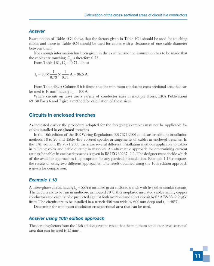
Examination of Table 4C4 shows that the factors given in Table 4C1 should be used for touching cables and those in Table 4C4 should be used for cables with a clearance of one cable diameter between them.
Not enough information has been given in the example and the assumption has to be made that the cables are touching. Cg is therefore 0.73.
From Table 4B1, Ca = 0.71. Thus:
I A At = × × =501
0 731
0 7196 5
. ..
From Table 4E2A Column 9 it is found that the minimum conductor cross-sectional area that can be used is 16 mm2 having Ita = 100 A.
Where circuits on trays use a variety of conductor sizes in multiple layers, ERA Publications 69–30 Parts 6 and 7 give a method for calculation of those sizes.
Circuits in enclosed trenches
As indicated earlier the procedure adopted for the foregoing examples may not be applicable for cables installed in enclosed trenches.
In the 16th edition of the IEE Wiring Regulations, BS 7671:2001, and earlier editions installation methods 18 to 20 and Table 4B3 covered specific arrangements of cables in enclosed trenches. In the 17th edition, BS 7671:2008 there are several different installation methods applicable to cables in building voids and cable ducting in masonry. An alternative approach for determining current ratings for cables in enclosed trenches is given in BS IEC 60287–2-1. The designer must decide which of the available approaches is appropriate for any particular installation. Example 1.13 compares the results of using two different approaches. The result obtained using the 16th edition approach is given for comparison.
Example 1.13
A three-phase circuit having Ib = 55 A is installed in an enclosed trench with five other similar circuits. The circuits are to be run in multicore armoured 70°C thermoplastic insulated cables having copper conductors and each is to be protected against both overload and short circuit by 63 A BS 88–2.2 ‘gG’ fuses. The circuits are to be installed in a trench 450 mm wide by 600 mm deep and ta = 40°C.
Determine the minimum conductor cross-sectional area that can be used.
Answer using 16th edition approach
The derating factors from the 16th edition gave the result that the minimum conductor cross-sectional area that can be used is 25 mm2.
Electrical Installations Calculations
12
Answer using 17th edition approach
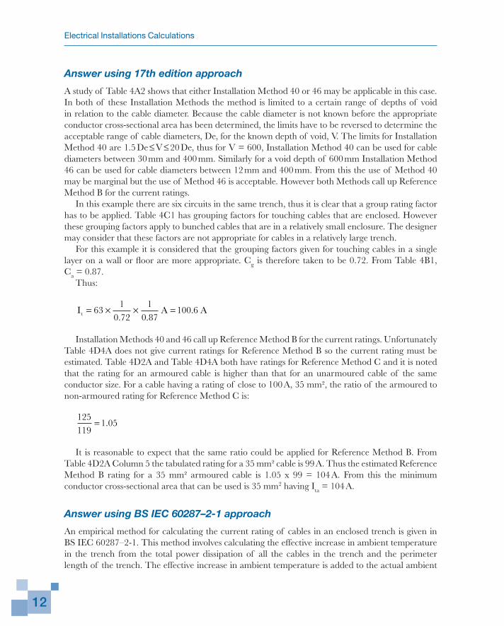
A study of Table 4A2 shows that either Installation Method 40 or 46 may be applicable in this case. In both of these Installation Methods the method is limited to a certain range of depths of void in relation to the cable diameter. Because the cable diameter is not known before the appropriate conductor cross-sectional area has been determined, the limits have to be reversed to determine the acceptable range of cable diameters, De, for the known depth of void, V. The limits for Installation Method 40 are 1.5 De ≤ V ≤ 20 De, thus for V = 600, Installation Method 40 can be used for cable diameters between 30 mm and 400 mm. Similarly for a void depth of 600 mm Installation Method 46 can be used for cable diameters between 12 mm and 400 mm. From this the use of Method 40 may be marginal but the use of Method 46 is acceptable. However both Methods call up Reference Method B for the current ratings.
In this example there are six circuits in the same trench, thus it is clear that a group rating factor has to be applied. Table 4C1 has grouping factors for touching cables that are enclosed. However these grouping factors apply to bunched cables that are in a relatively small enclosure. The designer may consider that these factors are not appropriate for cables in a relatively large trench.
For this example it is considered that the grouping factors given for touching cables in a single layer on a wall or floor are more appropriate. Cg is therefore taken to be 0.72. From Table 4B1, Ca = 0.87.
Thus:
I A At = × × =631
0 721
0 87100 6
. ..
Installation Methods 40 and 46 call up Reference Method B for the current ratings. Unfortunately Table 4D4A does not give current ratings for Reference Method B so the current rating must be estimated. Table 4D2A and Table 4D4A both have ratings for Reference Method C and it is noted that the rating for an armoured cable is higher than that for an unarmoured cable of the same conductor size. For a cable having a rating of close to 100 A, 35 mm², the ratio of the armoured to non-armoured rating for Reference Method C is:
125119
1 05= .
It is reasonable to expect that the same ratio could be applied for Reference Method B. From Table 4D2A Column 5 the tabulated rating for a 35 mm² cable is 99 A. Thus the estimated Reference Method B rating for a 35 mm² armoured cable is 1.05 x 99 = 104 A. From this the minimum conductor cross-sectional area that can be used is 35 mm2 having Ita = 104 A.
Answer using BS IEC 60287–2-1 approach
An empirical method for calculating the current rating of cables in an enclosed trench is given in BS IEC 60287–2-1. This method involves calculating the effective increase in ambient temperature in the trench from the total power dissipation of all the cables in the trench and the perimeter length of the trench. The effective increase in ambient temperature is added to the actual ambient
Calculation of the cross-sectional areas of circuit live conductors
13
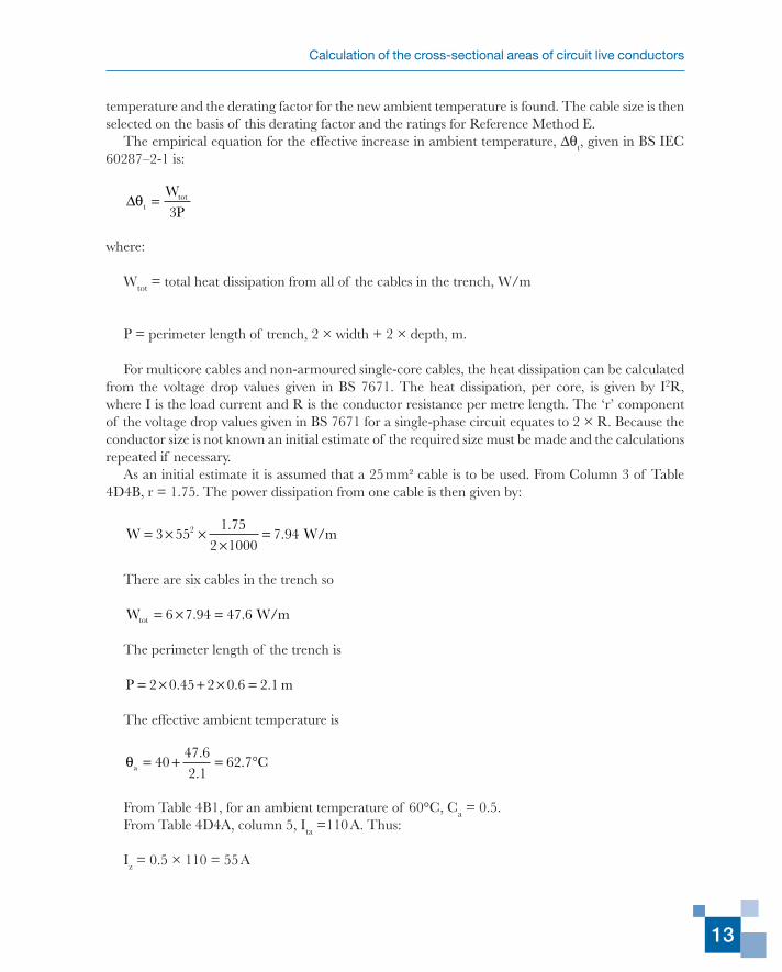
temperature and the derating factor for the new ambient temperature is found. The cable size is then selected on the basis of this derating factor and the ratings for Reference Method E.
The empirical equation for the effective increase in ambient temperature, ∆θt, given in BS IEC 60287–2-1 is:
∆θttotWP
=3
where:
Wtot = total heat dissipation from all of the cables in the trench, W/m
P = perimeter length of trench, 2 × width + 2 × depth, m.
For multicore cables and non-armoured single-core cables, the heat dissipation can be calculated from the voltage drop values given in BS 7671. The heat dissipation, per core, is given by I2R, where I is the load current and R is the conductor resistance per metre length. The ‘r’ component of the voltage drop values given in BS 7671 for a single-phase circuit equates to 2 × R. Because the conductor size is not known an initial estimate of the required size must be made and the calculations repeated if necessary.
As an initial estimate it is assumed that a 25 mm² cable is to be used. From Column 3 of Table 4D4B, r = 1.75. The power dissipation from one cable is then given by:
W = × ××
=3 551 75
2 10007 942 .
. W/m
There are six cables in the trench so
Wtot = × =6 7 94 47 6. . W/m
The perimeter length of the trench is
P = × + × =2 0 45 2 0 6 2 1. . . m
The effective ambient temperature is
θa = + = °4047 62 1
62 7..
. C
From Table 4B1, for an ambient temperature of 60°C, Ca = 0.5.From Table 4D4A, column 5, Ita =110 A. Thus:
Iz = 0.5 × 110 = 55 A
Electrical Installations Calculations
14
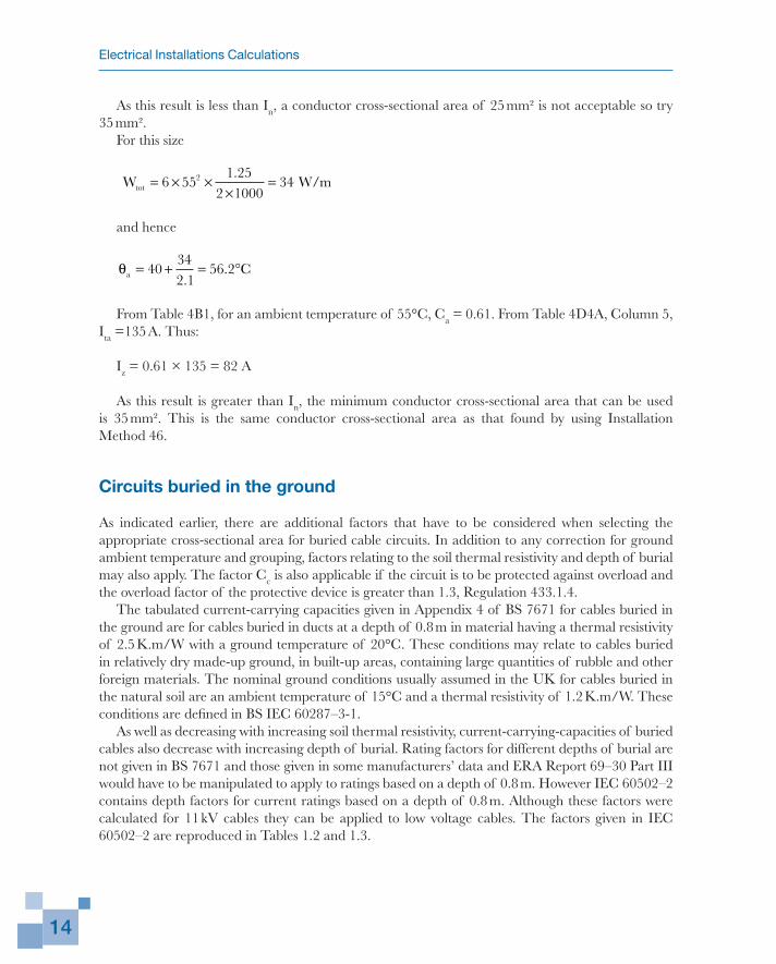
As this result is less than In, a conductor cross-sectional area of 25 mm² is not acceptable so try 35 mm².
For this size
Wtot = × ××
=6 551 25
2 1000342 .
W/m
and hence
θa = + = °40342 1
56 2.
. C
From Table 4B1, for an ambient temperature of 55°C, Ca = 0.61. From Table 4D4A, Column 5, Ita =135 A. Thus:
Iz = 0.61 × 135 = 82 A
As this result is greater than In, the minimum conductor cross-sectional area that can be used is 35 mm². This is the same conductor cross-sectional area as that found by using Installation Method 46.
Circuits buried in the ground
As indicated earlier, there are additional factors that have to be considered when selecting the appropriate cross-sectional area for buried cable circuits. In addition to any correction for ground ambient temperature and grouping, factors relating to the soil thermal resistivity and depth of burial may also apply. The factor Cc is also applicable if the circuit is to be protected against overload and the overload factor of the protective device is greater than 1.3, Regulation 433.1.4.
The tabulated current-carrying capacities given in Appendix 4 of BS 7671 for cables buried in the ground are for cables buried in ducts at a depth of 0.8 m in material having a thermal resistivity of 2.5 K.m/W with a ground temperature of 20°C. These conditions may relate to cables buried in relatively dry made-up ground, in built-up areas, containing large quantities of rubble and other foreign materials. The nominal ground conditions usually assumed in the UK for cables buried in the natural soil are an ambient temperature of 15°C and a thermal resistivity of 1.2 K.m/W. These conditions are defined in BS IEC 60287–3-1.
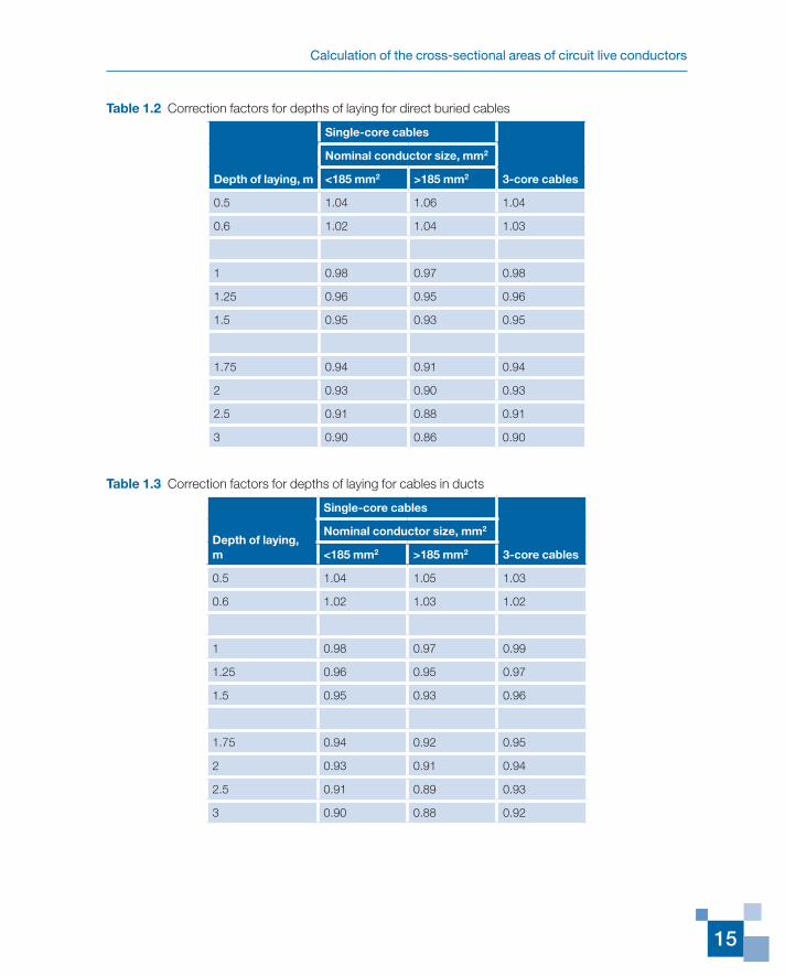
As well as decreasing with increasing soil thermal resistivity, current-carrying-capacities of buried cables also decrease with increasing depth of burial. Rating factors for different depths of burial are not given in BS 7671 and those given in some manufacturers’ data and ERA Report 69–30 Part III would have to be manipulated to apply to ratings based on a depth of 0.8 m. However IEC 60502–2 contains depth factors for current ratings based on a depth of 0.8 m. Although these factors were calculated for 11 kV cables they can be applied to low voltage cables. The factors given in IEC 60502–2 are reproduced in Tables 1.2 and 1.3.
Calculation of the cross-sectional areas of circuit live conductors
15
Table 1.2 Correction factors for depths of laying for direct buried cables
Depth of laying, m
Single-core cables
3-core cables
Nominal conductor size, mm2
<185 mm2 >185 mm2
0.5 1.04 1.06 1.04
0.6 1.02 1.04 1.03
1 0.98 0.97 0.98
1.25 0.96 0.95 0.96
1.5 0.95 0.93 0.95
1.75 0.94 0.91 0.94
2 0.93 0.90 0.93
2.5 0.91 0.88 0.91
3 0.90 0.86 0.90
Table 1.3 Correction factors for depths of laying for cables in ducts
Depth of laying, m
Single-core cables
3-core cables
Nominal conductor size, mm2
<185 mm2 >185 mm2
0.5 1.04 1.05 1.03
0.6 1.02 1.03 1.02
1 0.98 0.97 0.99
1.25 0.96 0.95 0.97
1.5 0.95 0.93 0.96
1.75 0.94 0.92 0.95
2 0.93 0.91 0.94
2.5 0.91 0.89 0.93
3 0.90 0.88 0.92
Electrical Installations Calculations
16
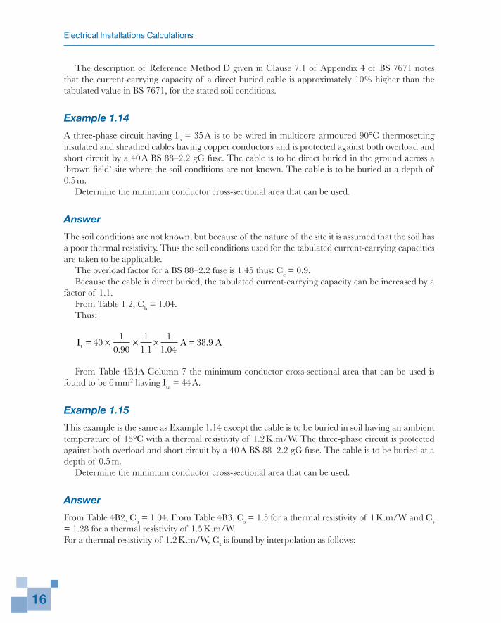
The description of Reference Method D given in Clause 7.1 of Appendix 4 of BS 7671 notes that the current-carrying capacity of a direct buried cable is approximately 10% higher than the tabulated value in BS 7671, for the stated soil conditions.
Example 1.14
A three-phase circuit having Ib = 35 A is to be wired in multicore armoured 90°C thermosetting insulated and sheathed cables having copper conductors and is protected against both overload and short circuit by a 40 A BS 88–2.2 gG fuse. The cable is to be direct buried in the ground across a ‘brown field’ site where the soil conditions are not known. The cable is to be buried at a depth of 0.5 m.
Determine the minimum conductor cross-sectional area that can be used.
Answer
The soil conditions are not known, but because of the nature of the site it is assumed that the soil has a poor thermal resistivity. Thus the soil conditions used for the tabulated current-carrying capacities are taken to be applicable.
The overload factor for a BS 88–2.2 fuse is 1.45 thus: Cc = 0.9.Because the cable is direct buried, the tabulated current-carrying capacity can be increased by a
factor of 1.1.From Table 1.2, Cb = 1.04.Thus:
I A At = × × × =401
0 901
1 11
1 0438 9
. . ..
From Table 4E4A Column 7 the minimum conductor cross-sectional area that can be used is found to be 6 mm2 having Ita = 44 A.
Example 1.15
This example is the same as Example 1.14 except the cable is to be buried in soil having an ambient temperature of 15°C with a thermal resistivity of 1.2 K.m/W. The three-phase circuit is protected against both overload and short circuit by a 40 A BS 88–2.2 gG fuse. The cable is to be buried at a depth of 0.5 m.
Determine the minimum conductor cross-sectional area that can be used.
Answer
From Table 4B2, Ca = 1.04. From Table 4B3, Cs = 1.5 for a thermal resistivity of 1 K.m/W and Cs = 1.28 for a thermal resistivity of 1.5 K.m/W.For a thermal resistivity of 1.2 K.m/W, Cs is found by interpolation as follows:
Calculation of the cross-sectional areas of circuit live conductors
17
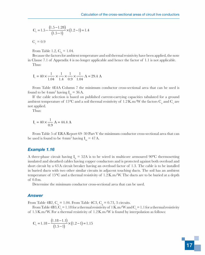
Cs = −−( )
−( ) × −( ) =1 51 5 1 28
1 5 11 2 1 1 4.
. .
.. .
Cc = 0.9
From Table 1.2, Cb = 1.04.Because the factors for ambient temperature and soil thermal resistivity have been applied, the note
in Clause 7.1 of Appendix 4 is no longer applicable and hence the factor of 1.1 is not applicable.Thus:
I A At = × × × × =401
1 041
1 41
0 91
1 0429 4
. . . ..
From Table 4E4A Column 7 the minimum conductor cross-sectional area that can be used is found to be 4 mm2 having Ita = 36 A.
If the cable selection is based on published current-carrying capacities tabulated for a ground ambient temperature of 15°C and a soil thermal resistivity of 1.2 K.m/W the factors Ca and Cs are not applied.
Thus:
I A At = × =401
0 944 4
..
From Table 5 of ERA Report 69–30 Part V the minimum conductor cross-sectional area that can be used is found to be 4 mm2 having Ita = 47 A.
Example 1.16
A three-phase circuit having Ib = 52A is to be wired in multicore armoured 90°C thermosetting insulated and sheathed cables having copper conductors and is protected against both overload and short circuit by a 63 A circuit breaker having an overload factor of 1.3. The cable is to be installed in buried ducts with two other similar circuits in adjacent touching ducts. The soil has an ambient temperature of 15°C and a thermal resistivity of 1.2 K.m/W. The ducts are to be buried at a depth of 0.8 m.
Determine the minimum conductor cross-sectional area that can be used.
Answer
From Table 4B2, Ca = 1.04. From Table 4C3, Cg = 0.73, 3 circuits.From Table 4B3, Cs = 1.18 for a thermal resistivity of 1 K.m/W and Cs = 1.1 for a thermal resistivity
of 1.5 K.m/W. For a thermal resistivity of 1.2 K.m/W is found by interpolation as follows:
Cs = −−( )−( ) × −( ) =1 18
1 18 1 1
1 5 11 2 1 1 15.
. .
.. .
Electrical Installations Calculations
18
Cc = 1
Thus:
I A At = × × × =631
1 041
1 151
0 7372 2
. . ..
From Table 4E4A Column 7 the minimum conductor cross-sectional area that can be used is found to be 16 mm2 having Ita = 75 A.
Grouped circuits not liable to simultaneous overload
Inspection of Table 4C1 of Appendix 4 of BS 7671 immediately shows that, particularly for circuits grouped in enclosures or bunched and clipped direct to a non-metallic surface, the grouping factor Cg can lead to a significant increase in the conductor cross-sectional area to be used.
However, for such grouped circuits, BS 7671 in item 5.1.2 and 6.2.2 of the Preface to the tables of conductor current-carrying capacities offers a method of limiting increases in conductor cross-sectional areas – provided that the grouped circuits are not liable to simultaneous overload.
This method consists of calculating It from:
II
C C C CAt
b
a i g c
=
and then calculating It from:
IC C
IC
IC
CAt
a i
n
cb
g
g
= +−
10 48
12
22
2
2.
Whichever is the greater of the two values of It so obtained is then used when inspecting the appropriate table of conductor current-carrying capacities to establish the conductor cross-sectional area having an actual tabulated current-carrying capacity (Ita) equal to or greater than that value of It.
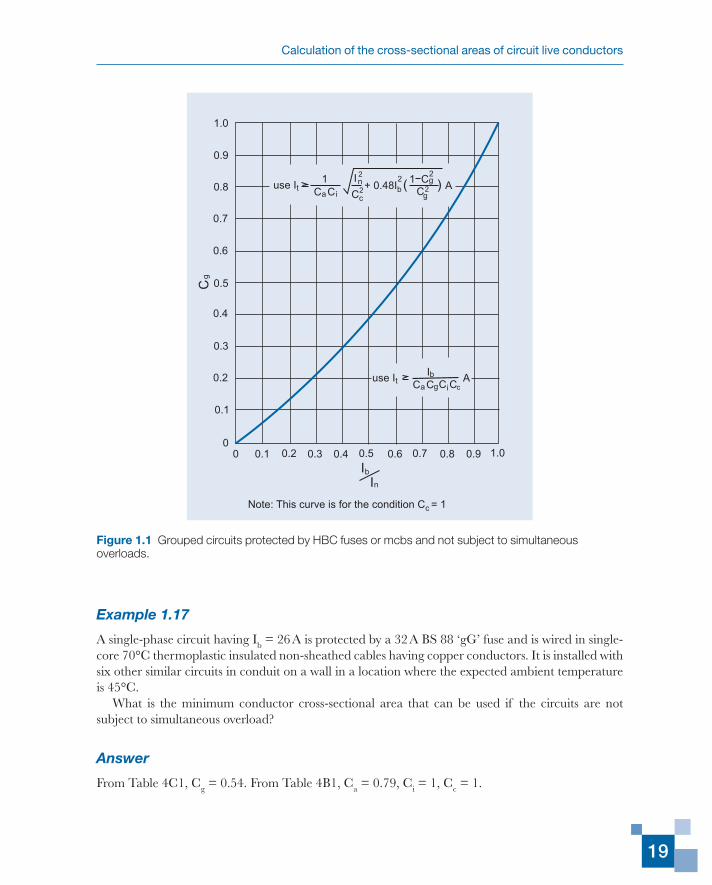
Figures 1.1 and 1.2 have been developed as a convenient design aid, for the conditions where Cc = 1, and are used in the following manner.
For a particular case, the values of Cg and Ib/In are known and Figure 1.1 immediately shows which of the two expressions gives the higher value of It.
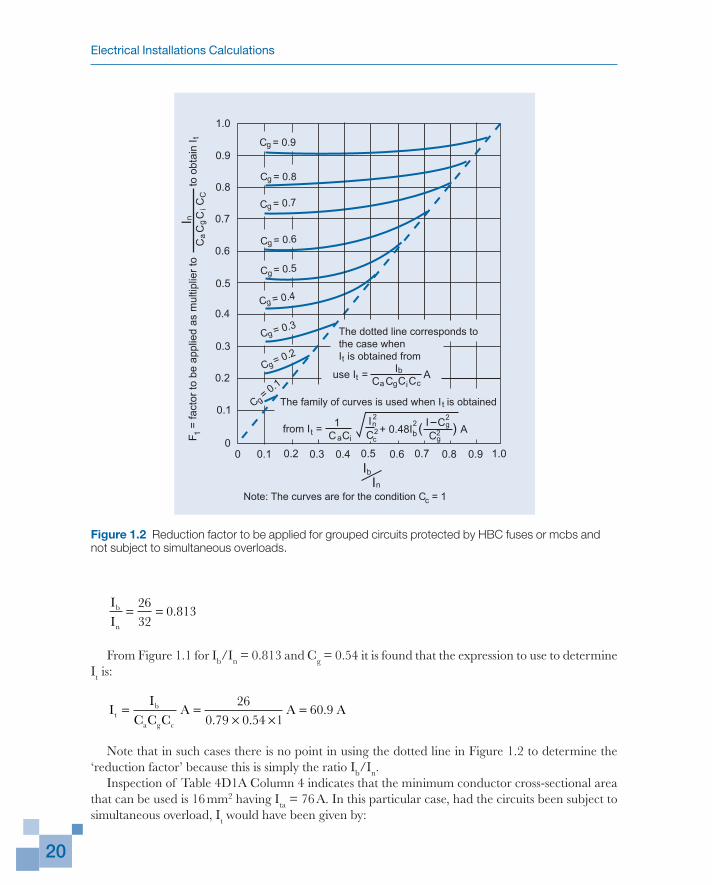
Figure 1.2, by using either the broken line (but see comment in Example 1.17) or the appropriate curve from the family of curves, gives the value of the reduction factor F1. As indicated, this factor F1 is applied as a multiplier to In/CaCgCi to obtain It which, as before, is used to determine the minimum conductor cross-sectional area that can be tolerated. Thus Figure 1.2 also gives a very rapid indication as to whether or not it is worthwhile taking advantage of this particular option.
Calculation of the cross-sectional areas of circuit live conductors
19
Example 1.17
A single-phase circuit having Ib = 26 A is protected by a 32 A BS 88 ‘gG’ fuse and is wired in single-core 70°C thermoplastic insulated non-sheathed cables having copper conductors. It is installed with six other similar circuits in conduit on a wall in a location where the expected ambient temperature is 45°C.
What is the minimum conductor cross-sectional area that can be used if the circuits are not subject to simultaneous overload?
Answer
From Table 4C1, Cg = 0.54. From Table 4B1, Ca = 0.79, Ci = 1, Cc = 1.
1.0
0.9
0.8
0.7
0.6
0.5
0.4
0.3
0.2
0.1
00 0.1 0.2 0.3 0.4 0.5 0.6 0.7 0.8 0.9 1.0
Cg
Ib
In
use I 1
C Cta i
+ 0.48I ( ) A n2
b2 1 C g
2
C g2
use I IC Ct
a g C Cib A
I
C2c
c
Note: This curve is for the condition C = 1c
Figure 1.1 Grouped circuits protected by HBC fuses or mcbs and not subject to simultaneous overloads.
Electrical Installations Calculations
20
II
b
n
= =2632
0 813.
From Figure 1.1 for Ib/In = 0.813 and Cg = 0.54 it is found that the expression to use to determine It is:
II
C C CA A At
b
a g c
= =× ×
=26
0 79 0 54 160 9
. ..
Note that in such cases there is no point in using the dotted line in Figure 1.2 to determine the ‘reduction factor’ because this is simply the ratio Ib/In.
Inspection of Table 4D1A Column 4 indicates that the minimum conductor cross-sectional area that can be used is 16 mm2 having Ita = 76 A. In this particular case, had the circuits been subject to simultaneous overload, It would have been given by:
1.0
0.9
0.8
0.7
0.6
0.5
0.4
0.3
0.2
0.1
00 0.1 0.2 0.3 0.4 0.5 0.6 0.7 0.8 0.9 1.0
IbIn
from I = 1C Cta i
+ 0.48I ( ) A nb2 I C g
2
C g2
use I = IC Ct
a g C Cib A
The dotted line corresponds tothe case whenI is obtained from
The family of curves is used when I is obtainedt
C = 0.9g
C = 0.8g
C = 0.7g
C = 0.6g
C = 0.5g
C = 0.4g
C = 0.3g
C = 0.2g
C = 0.1
g
t
c
IC
2
2c
Note: The curves are for the condition C = 1c
F =
fact
or to
be
appl
ied
as m
ultip
lier t
o
to
obta
in I
1t
C
C C
Ca
i
gI nC
Figure 1.2 Reduction factor to be applied for grouped circuits protected by HBC fuses or mcbs and not subject to simultaneous overloads.
Calculation of the cross-sectional areas of circuit live conductors
21
II
C C CA At
n
a g c
= =× ×
=32
0 79 0 54 175
. .
One could still have used a 16 mm2 conductor area, so no advantage has been gained because the circuits were not subject to simultaneous overload.
Example 1.18
Eight similar three-phase circuits are wired in 90°C thermosetting insulated multicore cables having copper conductors, these being bunched and clipped direct. ta = 50°C, Ib = 34 A and In = 40 A, the protection against overcurrent being provided by miniature circuit breakers.
If it can be assumed that the circuits are not subject to simultaneous overload, what is the minimum conductor cross-sectional area that can be used?
Answer
From Table 4C1, Cg = 0.52. From Table 4B1, Ca = 0.80, Ci = 1, Cc = 1.
II
b
n
= =3440
0 85.
For that value of Ib/In and Cg = 0.52, from Figure 1.1 it is found that the expression to determine It is:
II
C C CA A At
b
a g c
= =× ×
=34
0 80 0 52 181 7
. ..
From Table 4E2A Column 7 it is then found that the minimum conductor cross-sectional area to use is 16 mm2 having Ita = 96 A.
In this case some advantage has been gained because if one assumed that the circuits were subject to simultaneous overload, It would have been given by:
II
C C CA A At
n
a g c
= =× ×
=40
0 80 0 52 196 2
. ..
and it would have been found that the minimum conductor cross-sectional area would be 25 mm2.
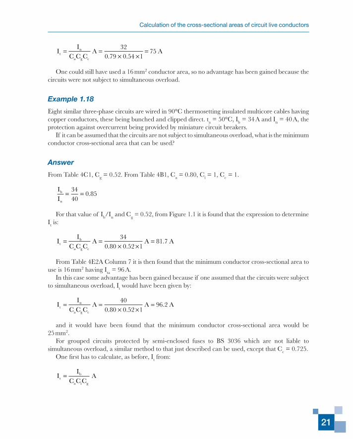
For grouped circuits protected by semi-enclosed fuses to BS 3036 which are not liable to simultaneous overload, a similar method to that just described can be used, except that Cc = 0.725.
One first has to calculate, as before, It from:
II
C C CAt
b
a i g
=
Electrical Installations Calculations
22
and then from:
IC C
IC
IC
CAt
a i
n
c
b g
g
= +−
10 48
12
2 2
2
2.
Whichever is the greater of the two values obtained is then used when inspecting the appropriate table of conductor current-carrying capacities to establish the conductor cross-sectional area having an actual tabulated current-carrying capacity (Ita) equal to or greater than that value of It.
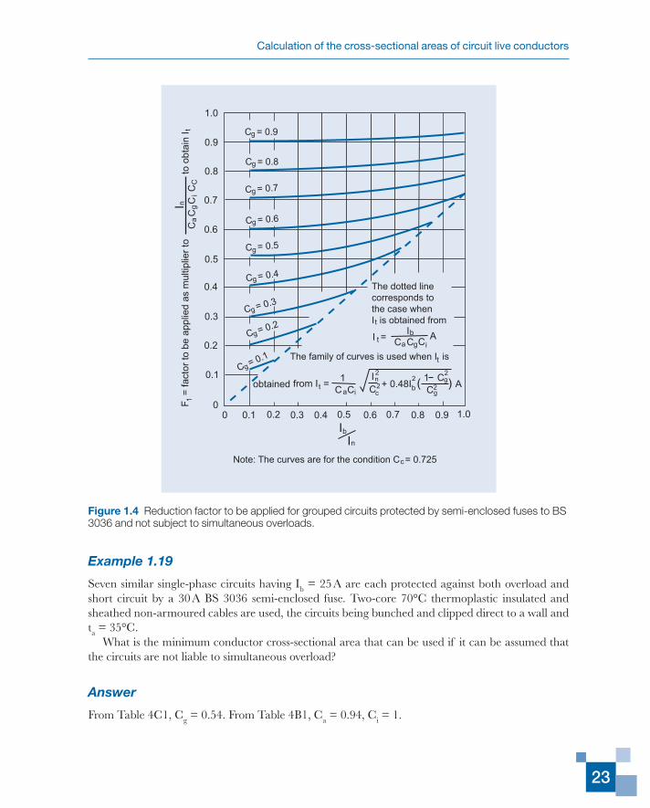
Figures 1.3 and 1.4 have been developed as a convenient design aid, similar to Figures 1.1 and 1.2 but for circuits protected by semi-enclosed fuses.
1.0
0.9
0.8
0.7
0.6
0.5
0.4
0.3
0.2
0.1
00 0.1 0.2 0.3 0.4 0.5 0.6 0.7 0.8 0.9 1.0
Cg
Ib
In
use I I
C Cta g Ci
b A
use I 1
C Cta i
+ 0.48I ( ) A n2
b2 1 C g
2
C g2
I
C2c
Note: This curve is for the condition C = 0.725c
Figure 1.3 Grouped circuits protected by semi-enclosed fuses to BS 3036 and not subject to simultaneous overloads.
Calculation of the cross-sectional areas of circuit live conductors
23
Example 1.19
Seven similar single-phase circuits having Ib = 25 A are each protected against both overload and short circuit by a 30 A BS 3036 semi-enclosed fuse. Two-core 70°C thermoplastic insulated and sheathed non-armoured cables are used, the circuits being bunched and clipped direct to a wall and ta = 35°C.
What is the minimum conductor cross-sectional area that can be used if it can be assumed that the circuits are not liable to simultaneous overload?
Answer
From Table 4C1, Cg = 0.54. From Table 4B1, Ca = 0.94, Ci = 1.
1.0
0.9
0.8
0.7
0.6
0.5
0.4
0.3
0.2
0.1
00 0.1 0.2 0.3 0.4 0.5 0.6 0.7 0.8 0.9 1.0
Ib
In
I = I
C Cta g Ci
b A
The family of curves is used when I ist
C = 0.9g
C = 0.8g
C = 0.7g
C = 0.6g
C = 0.5g
C = 0.4g
C = 0.3g
C = 0.2g
C = 0.1g
The dotted linecorresponds tothe case whenI is obtained fromt
obtained from I = 1
C Cta i
+ 0.48I ( ) A nb2 1 C g
2
C g2IC
2
2c
F =
fact
or to
be
appl
ied
as m
ultip
lier
to
to
obt
ain
I1
t
C C
C C
ai
gI n
C
Note: The curves are for the condition C = 0.725c
Figure 1.4 Reduction factor to be applied for grouped circuits protected by semi-enclosed fuses to BS 3036 and not subject to simultaneous overloads.
Electrical Installations Calculations
24
II
b
n
= =2530
0 83.
From Figure 1.3 for Ib/In = 0.83 and Cg = 0.54 it is seen that It has to be found from:
IC C
IC
IC
CAt
a i
n
cb
g
g
= +−
10 48
12
22
2
2.
From Figure 1.4 it is then found that the ‘reduction factor’ F1 is approximately 0.65, so that:
IF I
C C CA A At
n
c g a
=×
× ×=
×× ×
=1 0 65 300 725 0 54 0 94
53.
. . .
From Table 4D2A Column 6 the minimum conductor cross-sectional area that can be used is found to be 10 mm2 having Ita = 63 A.
In those cases where there is very little difference between It and Ita it would be advisable to use the actual formula as a check. In the present case there is no need to do this, but It so obtained would have been found to be 50.9 A.
BS 7671 offers another way of effecting some reduction in the cross-sectional areas of grouped cables as indicated in Note 9 to Table 4C1.
Normally a group of N loaded cables require a grouping correction factor of Cg applied to the actual tabulated current-carrying capacity (Ita). However, if M cables of that group are known to be carrying currents not greater than 0.3CgIta A, the other cables can be sized by using the grouping correction factor corresponding to (N – M) cables.
Circuits in low ambient temperatures
All the examples so far, except those for buried cables, have concerned an ambient temperature of 30°C or greater. Consider now the case where the expected ambient temperature is less than 30°C (i.e. is less than the reference ambient temperature).
Table 4B1 of BS 7671 gives ambient temperature correction factors principally for ambient temperatures exceeding 30°C. These factors are based on the fact that with such ambient temperatures the limiting parameter is the maximum normal operating temperature for the type of cable insulation concerned and are given by:
Ct t
tap a
p
=−−
30
These factors therefore apply if the protective device is providing overload protection with or without short circuit protection or is providing short circuit protection only.
For ambient temperatures below 30°C, however, it will be found that the limiting parameter is now the maximum tolerable temperature under overload conditions (to) where:
Calculation of the cross-sectional areas of circuit live conductors
25
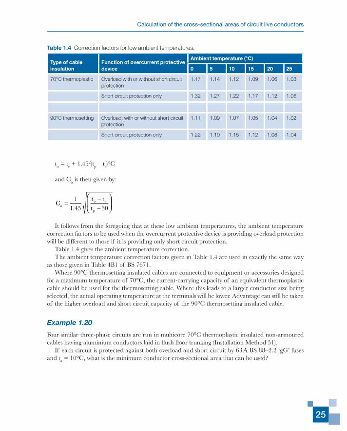
to = tr + 1.452(tp – tr)°C
and Ca is then given by:
Ct tta
o a
p
=−−
11 45 30.
It follows from the foregoing that at these low ambient temperatures, the ambient temperature correction factors to be used when the overcurrent protective device is providing overload protection will be different to those if it is providing only short circuit protection.
Table 1.4 gives the ambient temperature correction.The ambient temperature correction factors given in Table 1.4 are used in exactly the same way
as those given in Table 4B1 of BS 7671.Where 90°C thermosetting insulated cables are connected to equipment or accessories designed
for a maximum temperature of 70°C, the current-carrying capacity of an equivalent thermoplastic cable should be used for the thermosetting cable. Where this leads to a larger conductor size being selected, the actual operating temperature at the terminals will be lower. Advantage can still be taken of the higher overload and short circuit capacity of the 90°C thermosetting insulated cable.
Example 1.20
Four similar three-phase circuits are run in multicore 70°C thermoplastic insulated non-armoured cables having aluminium conductors laid in flush floor trunking (Installation Method 51).
If each circuit is protected against both overload and short circuit by 63 A BS 88–2.2 ‘gG’ fuses and ta = 10°C, what is the minimum conductor cross-sectional area that can be used?
Table 1.4 Correction factors for low ambient temperatures.
Type of cable insulation
Function of overcurrent protective device
Ambient temperature (°C)
0 5 10 15 20 25
70°C thermoplastic Overload with or without short circuit protection
1.17 1.14 1.12 1.09 1.06 1.03
Short circuit protection only 1.32 1.27 1.22 1.17 1.12 1.06
90°C thermosetting Overload, with or without short circuit protection
1.11 1.09 1.07 1.05 1.04 1.02
Short circuit protection only 1.22 1.19 1.15 1.12 1.08 1.04
Electrical Installations Calculations
26
Answer
From Table 4A2 the Reference Method is Method B.From Table 4C1, Cg = 0.65. From Table 1.4 above, Ca = 1.12.Thus:
I A At = × × =631
0 651
1 1286 5
. ..
From Table 4H2A Column 5 the minimum conductor cross-sectional area that can be used is found to be 50 mm2, having Ita = 92 A.
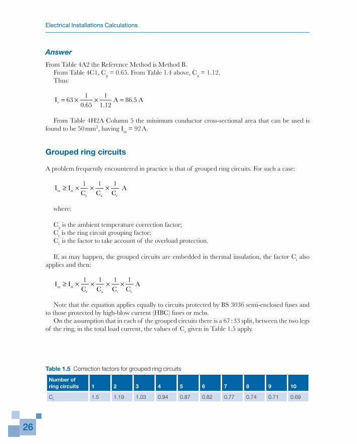
Grouped ring circuits
A problem frequently encountered in practice is that of grouped ring circuits. For such a case:
I IC C Cta n
r a c
≥ × × ×1 1 1
A
where:
Ca is the ambient temperature correction factor;
Cr is the ring circuit grouping factor;
Cc is the factor to take account of the overload protection.
If, as may happen, the grouped circuits are embedded in thermal insulation, the factor Ci also applies and then:
I IC C C C
Ata nr a i c
≥ × × × ×1 1 1 1
Note that the equation applies equally to circuits protected by BS 3036 semi-enclosed fuses and to those protected by high-blow current (HBC) fuses or mcbs.
On the assumption that in each of the grouped circuits there is a 67 : 33 split, between the two legs of the ring, in the total load current, the values of Cr given in Table 1.5 apply.
Table 1.5 Correction factors for grouped ring circuits
Number of ring circuits 1 2 3 4 5 6 7 8 9 10
Cr 1.5 1.19 1.03 0.94 0.87 0.82 0.77 0.74 0.71 0.69
Calculation of the cross-sectional areas of circuit live conductors
27
Example 1.21
Eight single-phase ring circuits are grouped in a common trunking. It is intended to use two-core (with cpc) 70°C thermoplastic insulated and sheathed flat cables having copper conductors.
If ta = 40°C and each circuit is to be protected by a 32 A mcb, what is the minimum conductor cross-sectional area that can be used?
Answer
From Table 1.5 earlier, Cr = 0.74. From Table 4B1, Ca = 0.87. Also Cc = 1.Thus:
I A At = × × =321
0 741
0 8749 7
. ..
Because Table 4D5A does not include current-carrying capacities for flat twin and earth cables in trunking, Table 4D2A has to be consulted. From Column 4 of this table it is found that the minimum conductor cross-sectional area that can be used is 10 mm2 having Ita= 52 A.
Motor circuits subject to frequent stopping and starting
Regulation 552.1.1 requires that where a motor is intended for intermittent duty and for frequent stopping and starting, account shall be taken of any cumulative effects of the starting periods upon the temperature rise of the equipment of the circuit. That equipment, of course, includes the cables feeding the motor.
When motors are regularly restarted soon after they have been stopped the cables supplying the motor may not have time to cool to close to the ambient temperature, this time being anything from about 20 minutes to several hours depending on their size and the method of installation.
Furthermore, starting currents (for direct-on-line starting) can be between 5 and 8 times the full load current.
The calculation of any accurate factor to take account of frequent stopping and starting is complex and requires that information is provided on:
(a) the actual magnitude of the starting current;(b) the duration of, and rate of decay, of the starting current;(c) the full load current;(d) the first choice cable size to calculate its time constant;(e) the time intervals between stopping and starting.
It is suggested that the cable cross-sectional area is chosen on the basis of its current-carrying capacity being 1.4 times the full load current.
Electrical Installations Calculations
28
Example 1.22
A 7.5 kW 230 V single-phase motor is subject to frequent stopping and starting. The cable supplying the motor via a direct-on-line starter is two-core non-armoured cable having 90°C thermosetting insulation and copper conductors, clipped direct.
If the ambient temperature is 50°C, what should be the conductor cross-sectional area?
Answer
The full load current is:
7 5 1000230
32 6.
.×
=A A
The conductor current-carrying capacity should therefore be at least 1.4 × 32.6 A = 45.6 A.As the ambient temperature is 50°C, from Table 4B1 (assuming the circuit overcurrent protective
device is other than a BS 3036 semi-enclosed fuse), Ca is found to be 0.82.The cross-sectional area of the conductor should therefore have Ita of at least 45.6/0.82 A =
55.6 A.From Table 4E2A Column 6 it is found that the minimum conductor cross-sectional area to use
is 6 mm2 having Ita = 58 A.Due account has to be taken of the motor efficiency and motor power factor where these are
known.
Example 1.23
A 400 V three-phase motor has a rating of 15 kW at a power factor of 0.8 lagging, the efficiency being 90%.
If this motor is subject to frequent stopping and starting and it is intended to use a multicore armoured 90°C thermosetting insulated cable having copper conductors, installed in free air, what should be their cross-sectional area when ta = 35°C?
Answer
The full load current of the motor is:
15 1000
0 8 0 9 3 40030
×× × ×
=. .
(A A per phase)
The conductor current-carrying capacity should therefore be at least:
1.4 × 30 A = 42 A
As the ambient temperature is 35°C, from Table 4B1, Ca is found to be 0.96.The cross-sectional area of the conductors should therefore have Ita of at least:
Calculation of the cross-sectional areas of circuit live conductors
29
42/0.96 A = 43.8 A
From Table 4E4A Column 5 it is found that the minimum conductor cross-sectional area is 4 mm2 having Ita = 44 A.
Note that in this example no mention is made of the nominal current rating of the overcurrent protective device for the motor circuit. The omission is deliberate because that device, in very many motor circuits, is providing short circuit protection only. Overload protection is provided by, for example, thermal overload relays in the motor starter. The nominal current rating of the overcurrent protective device in the motor circuit and its operating characteristics must be such as to provide adequate short circuit protection to the circuit conductors (i.e. give compliance with the adiabatic equation in Regulation 434.5.2), but not cause disconnection of the motor circuit because of high starting currents.
Circuits for star-delta starting of motors
Another problem associated with motors is the current demand when star-delta starting is used. With star-delta starters, six conductors (two per phase) are required between the starter and the motor, the star or delta connections being made in the starter.
During the running condition, the current carried by each of the six cables is 1/√3 times that of the supply cables to the starter (the connection being delta). If the motor cables are not grouped they require a current-carrying capacity 58% that of the supply cables. In practice it is far more likely that the motor cables are grouped together. Therefore the grouping correction factor (Cg) for two circuits applies and the required current-carrying capacity for the motor cables becomes 72% that for the supply cables, assuming the cables are either enclosed or bunched and clipped to a non-metallic surface.
If a delta-connected motor is started direct-on-line the starting current may be between 5 and 8 times the full load current depending on the size and design of that motor. When star-delta starting is used, the current taken from the supply is one-third of that taken when starting direct on line. Hence the starting current in star may be between 1.67 and 2.67 times the full load current. During the starting period, because the star connection is used, the current in each of the motor cables equals that in the supply cables.
Because the starting current is only carried for a short period, advantage can be taken of the thermal inertia of the cables and the cables chosen because their running condition will be satisfactory for the starting current.
Example 1.24
A 400 V three-phase 20 kW motor has a power factor of 0.86 lagging and an efficiency of 90%. Star-delta starting is to be used. The supply cables to the starter are single-core 90°C thermosetting insulated (copper conductors) in conduit. The motor cables from the starter are also single-core thermosetting insulated (copper conductors) and in another length of conduit.
What is the minimum conductor cross-sectional area for both circuits if ta = 30°C?
Electrical Installations Calculations
30
Answer
The line current =×
× × ×=
20 1000
3 400 0 86 0 9037 3
. ..A A
There are no correction factors to be applied.From Table 4E1A Column 5, it is found that the minimum conductor cross-sectional area for the
supply cables is 6 mm2 having Ita = 48 A.For the cables from the starter to the motor, each cable carries:
37 3
321 5
..A A=
But now it is necessary to apply the grouping factor for two circuits, which from Table 4C1 is 0.8. Thus:
I A At = =21 50 8
26 9..
.
Again from Table 4E1A Column 5 it is found that these cables can be of 2.5 mm2 cross-sectional area, having Ita = 28 A.
As already stated, although during starting the cables between the motor and the starter may be carrying a current of 37.3 × 2.67 A (= 99.6 A), the time the motor is held in star will generally be less than the time taken for these cables to reach the maximum permitted normal operating temperature.
Change of parameters of already installed circuits
The occasion may arise, for example when there is a change of tenancy of the premises concerned or it is intended to change the load or other circuit details, that the user wishes to determine whether an already installed cable will be adequate. In such cases the following method should be used.
The type of cable and its cross-sectional area are established so that the relevant table in Appendix 4 of BS 7671 and the appropriate column in that table are identified. From that table and column, Ita is obtained.
Then determine the product:
Ita × Ca × Cg × CI x Cc A.
Denote this product by ItcA.The cable concerned could therefore be used:
(a) for a circuit protected against both overload and short circuit by an HBC fuse or an mcb having a nominal current rating not greater than ItcA, and when the design current (Ib) of the circuit is less than that nominal current rating; or
Calculation of the cross-sectional areas of circuit live conductors
31
(b) for a circuit only protected against short circuit by an HBC fuse or mcb where the design current of the circuit is not greater than Itc A. The nominal current rating of the device can be greater than Itc (see Regulation 434.5.1) and is determined by the load characteristics together with the need to comply with Regulation 434.5.2.
If it is intended to use semi-enclosed fuses to BS 3036 then:
Itc = Ita × Ca × Cg × Ci × 0.725 A
but only if it is intended that the fuses are to give overload protection, with or without short circuit protection. In the unlikely event that such a fuse is intended to give only short circuit protection then the 0.725 factor is not used to determine Itc.
The symbol Itc has been used here in an attempt to clarify a point which sometimes causes confusion. When the overcurrent protective device is other than a semi-enclosed fuse to BS 3036, Itc has exactly the same identity as what is termed in BS 7671 the current-carrying capacity for continuous service under the particular installation conditions concerned and denoted by Iz.
When the overcurrent protection device is a semi-enclosed fuse to BS 3036, Iz is given by:
Iz = Ita × Ca × Cg × Ci A,
i.e. exactly the same expression as that for HBC fuses and mcbs. In other words, the effective current-carrying capacity of a conductor is totally independent of the type of overcurrent protective device associated with that conductor.
The factor 0.725 is only applied when determining the nominal current of a semi-enclosed fuse that can be used for a given conductor to take account of the higher fusing factor of such a fuse.
Example 1.25
An existing cable for a three-phase circuit is multicore non-armoured 70°C thermoplastic insulated having copper conductors of 25 mm2 cross-sectional area and is installed with five other similar cables in trunking.
What is the maximum nominal current of ‘gG’ fuses to BS 88–2.2 that can be used to protect this cable against both overload and short circuit if ta = 50°C?
Answer
From Table 4D2A Column 5, Ita = 80 A.From Table 4C1, Cg = 0.57 (there being a total of six circuits). From Table 4B1, Ca = 0.71.As Ci = 1,
Itc = 80 × 0.57 × 0.71 A = 32.4 A.
From the standard nominal current ratings for BS 88–2.2 fuses the maximum that can be used is 32 A. The design current Ib also must not exceed 32 A.
Electrical Installations Calculations
32
Example 1.26
An existing cable for a three-phase circuit is multicore armoured having 90°C thermosetting insulation and copper conductors of 35 mm2 cross-sectional area. It is clipped direct and is not bunched with any other cable.
If ta = 10°C and it is intended to protect the cable against short circuit current only, using HBC fuses, what is the maximum design current that can be tolerated?
Answer
From Table 1.4 of this Chapter, Ca = 1.15. Also Cg = 1 and Ci = 1. From Table 4E4A Column 3, Ita = 154 A.
Then:
Itc = 154 × 1.15 A= 177 A.
The maximum value of Ib therefore is 177 A.The nominal current rating of the HBC fuse may be greater than 177 A. It will be determined by
the load characteristics and will possibly be limited by the need to comply with Regulation 434.5.2.
Example 1.27
An existing cable is a two-core flat 70°C thermoplastic insulated cable having copper conductors of 16 mm2 which is clipped direct, bunched with four other similar cables.
If ta = 40°C and it is intended to protect the cable using a BS 3036 semi-enclosed fuse against overload, what is the maximum nominal rating that fuse can have?
Answer
From Table 4D5A, Column 6, Tta = 85 A. From Table 4C1, Cg = 0.60. From Table 4B1, Ca = 0.87.
Thus:
Itc = 85 × 0.60 × 0.87 × 0.725 A = 32.2 A
The maximum nominal current rating of the semi-enclosed fuse is therefore 30 A.The design current of the circuit also must not exceed 30 A.
Example 1.28
An existing cable is an armoured multicore cable having aluminium conductors of 70 mm2 cross-sectional area and 90°C thermosetting insulation. It is clipped direct to a non-metallic surface, not grouped with the cables of other circuits and ta = 50°C. The three-phase equipment fed by this cable is to be changed for equipment having a much higher kW rating and it is proposed to run a similar cable in parallel with that existing.
Calculation of the cross-sectional areas of circuit live conductors
33
If overcurrent protection (both overload and short circuit) is to be provided by BS 88–2.2 ‘gG’ fuses, what is the maximum nominal rating of those fuses and the maximum load current for the circuit?
Answer
From Table 4J4A, Column 3, Ita = 174 A. From Table 4B1, Ca = 0.82.Assuming that the additional cable will be touching or very close to the original cable it is also
necessary to apply the appropriate grouping factor, Cg.From Table 4C1, Cg = 0.85.Thus:
Itc = 174 × 0.82 × 0.85 A = 121A
As there are two identical cables in parallel this value has to be doubled, i.e. Itc = 242 A.From the standard nominal ratings for BS 88–2.2 ‘gG’ fuses it is found that the maximum that can
be used is 200 A and this is also the maximum value of Ib that can be tolerated for the circuit.
Admixtures of cable sizes in enclosures
Last, but far from least in this chapter the problem of mixed cable sizes and loads in trunking or other cable enclosures is considered.
The table of grouping correction factors (Table 4C1) in BS 7671, as indicated in Note 1 to that table, is applicable only to groups of cables where the cables are all of a similar size and are equally loaded. For this reason all the examples so far given in this chapter have concerned such groups but in practice it is infinitely more likely that trunking or conduit will contain cables of various sizes and with different loadings.
Where the range of sizes in a particular enclosure is not great, using the appropriate grouping correction factor from Table 4C1 can be justified. Where a wide range of sizes is accommodated in an enclosure, however, using the Table 4C1 correction factor can lead to oversizing the large cables but undersizing of the small cables.
The following method is based on one that was developed by Mr N.S. Bryant when he was with Pirelli General plc and put forward by him at an IEE discussion meeting in March 1984. There are six steps in the method and, for the purpose of illustration, after the description of each step the values for the specific example chosen are given.
Example 1.29
It is intended to run in 75 mm × 50 mm trunking the following circuits:
Circuit 1 Three-phase circuit Ib = 60 A
Circuit 2 Three-phase circuit Ib = 50 A
Circuit 3 Single-phase circuit Ib = 40 A
Circuit 4 Single-phase circuit Ib = 30 A
Circuit 5 Single-phase circuit Ib = 5 A
Electrical Installations Calculations
34
Circuit 6 Single-phase circuit Ib = 5 A
Circuit 7 Single-phase circuit Ib = 5 A
The expected ambient temperature is 30°C. Determine the conductor cross-sectional areas, when single-core 70°C thermoplastic insulated cables having copper conductors are used for all the circuits and check that they are thermally adequate.
Answer
Step 1Establish the conductor cross-sectional areas based on voltage drop requirements or by experience or by applying a single grouping correction factor.
Assume it is decided to use the following cables:
Circuit 1 3 cables 35 mm2
Circuit 2 3 cables 35 mm2
Circuit 3 2 cables 25 mm2
Circuit 4 2 cables 25 mm2
Circuit 5 2 cables 1.5 mm2
Circuit 6 2 cables 1.5 mm2
Circuit 7 2 cables 1.5 mm2
Step 2Calculate the ‘fill factor’ for the chosen sizes of cable and trunking where:
fill factorsum of the overall cable cross-sectional areas
=iinternal area of the trunking
The cable cross-sectional areas are found from the cable manufacturer’s data either as such or, if a cable overall diameter (De) is given, by the equation:
π4
2 2D mme
For the example, the cable cross-sectional areas are:
for 35 mm2 95 mm2
for 25 mm2 5.4 mm2
for 1.5 mm2 9.1 mm2
The sum of all the cable cross-sectional areas is:
(6 × 95) + (4 × 75.4) + (6 × 9.1) mm2 = 926 mm2
The internal area of the trunking is:
Calculation of the cross-sectional areas of circuit live conductors
35
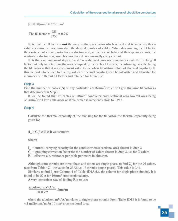
(75 × 50) mm2 = 3750 mm2
The fill factor = =926
37500 247.
Note that the fill factor is not the same as the space factor which is used to determine whether a cable enclosure can accommodate the desired number of cables. When determining the fill factor the existence of circuit protective conductors and, in the case of balanced three-phase circuits, the neutral conductor, is ignored because they do not normally carry current.
Note that examination of steps 2, 3 and 5 reveals that it is not necessary to calculate the trunking fill factor but only to determine the area occupied by the cables. However, the advantage in calculating the fill factor is that it is a convenient value to use when tabulating values of thermal capability. If this method is to be used frequently, values of thermal capability can be calculated and tabulated for a number of different fill factors and retained for future use.
Step 3Find the number of cables (N) of any particular size (S mm2) which will give the same fill factor as that determined in Step 2.
It will be found that 26 cables of 10 mm2 conductor cross-sectional area (overall area being 36.3 mm2) will give a fill factor of 0.252 which is sufficiently close to 0.247.
Step 4
Calculate the thermal capability of the trunking for the fill factor, the thermal capability being given by:
(Ita × Cg)2 × N × R watts/metre
where:
Ita = current-carrying capacity for the conductor cross-sectional area chosen in Step 3
Cg = grouping correction factor for the number of cables chosen in Step 3, i.e. for N cables
R = effective a.c. resistance per cable per metre in ohms/m.
Although some circuits are three-phase and others are single-phase, to find Cg for the 26 cables, take from Table 4C1 the value for 26/2, i.e. 13 circuits (single-phase). This value is 0.44.
Similarly to find Ita use Column 4 of Table 4D1A (i.e. the column for single-phase circuits). It is found to be 57 A for 10 mm2 cross-sectional area.
A very convenient way of finding R is to use:
tabulated mV A m1000 2×
ohms m
where the tabulated mV/A/m relates to single-phase circuits. From Table 4D1B it is found to be 4.4 milliohms/m for 10 mm2 cross-sectional area.
Electrical Installations Calculations
36
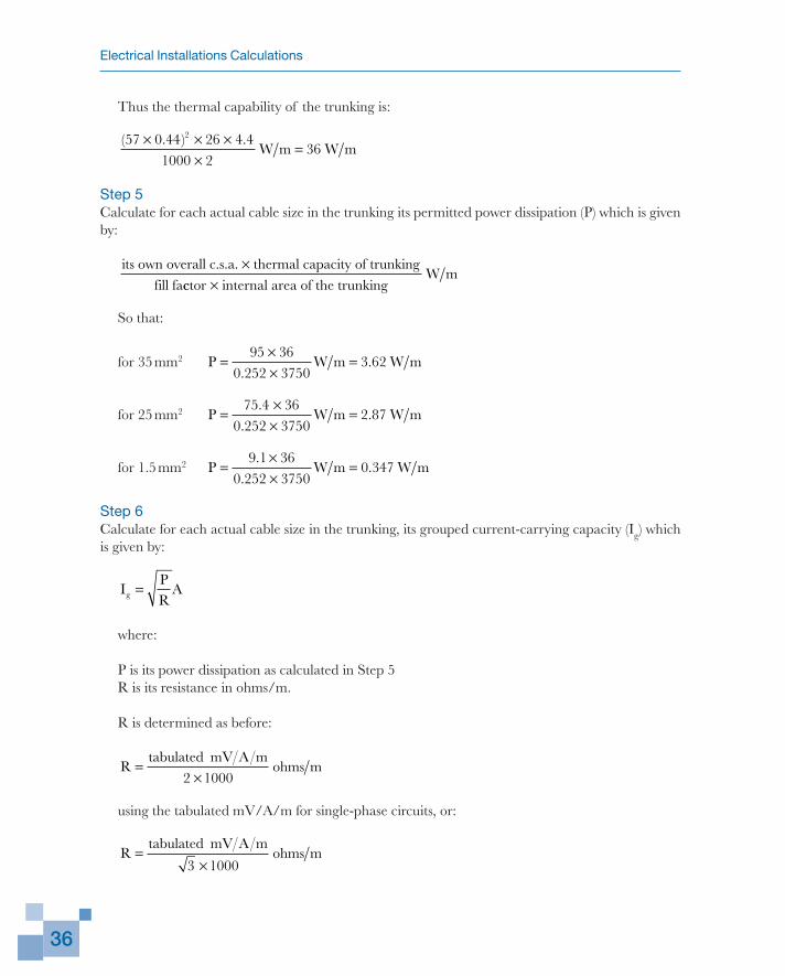
Thus the thermal capability of the trunking is:
( . ) .57 0 44 26 4 41000 2
362× × ×
×=W m W m
Step 5Calculate for each actual cable size in the trunking its permitted power dissipation (P) which is given by:
its own overall c.s.a. thermal capacity of trunkingfill fa
×cctor internal area of the trunking×
W m
So that:
for 35 mm2 P W m W m=××
=95 36
0 252 37503 62
..
for 25 mm2 P W m W m=×
×=
75 4 360 252 3750
2 87.
..
for 1.5 mm2 P W m W m=××
=9 1 36
0 252 37500 347
..
.
Step 6Calculate for each actual cable size in the trunking, its grouped current-carrying capacity (Ig) which is given by:
IPR
Ag =
where:
P is its power dissipation as calculated in Step 5
R is its resistance in ohms/m.
R is determined as before:
Rtabulated m
ohms m=×
mV A2 1000
using the tabulated mV/A/m for single-phase circuits, or:
Rtabulated m
ohms m=× mV A
3 1000
Calculation of the cross-sectional areas of circuit live conductors
37
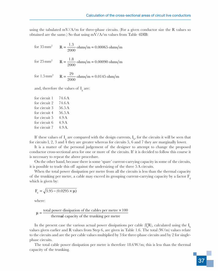
using the tabulated mV/A/m for three-phase circuits. (For a given conductor size the R values so obtained are the same.) So that using mV/A/m values from Table 4DIB:
for 35 mm2 R ohms m ohms m= =1 3
20000 00065
..
for 25 mm2 R ohms m ohms m= =1 8
20000 00090
..
for 1.5 mm2 R ohms m ohm m= =29
20000 0145.
and, therefore the values of Ig are:
for circuit 1 74.6 A
for circuit 2 74.6 A
for circuit 3 56.5 A
for circuit 4 56.5 A
for circuit 5 4.9 A
for circuit 6 4.9 A
for circuit 7 4.9 A.
If these values of Ig are compared with the design currents, Ib, for the circuits it will be seen that for circuits l, 2, 3 and 4 they are greater whereas for circuits 5, 6 and 7 they are marginally lower.
It is a matter of the personal judgement of the designer to attempt to change the proposed conductor cross-sectional area for one or more of the circuits. If it is decided to follow this course it is necessary to repeat the above procedure.
On the other hand, because there is some ‘spare’ current-carrying capacity in some of the circuits, it is possible to trade this off against the undersizing of the three 5 A circuits.
When the total power dissipation per metre from all the circuits is less than the thermal capacity of the trunking per metre, a cable may exceed its grouping current-carrying capacity by a factor Fg which is given by:
Fg = − ×3 95 0 0295. ( . µ)
where:
µ =×total power dissipation of the cables per metre 100
thermaal capacity of the trunking per metre
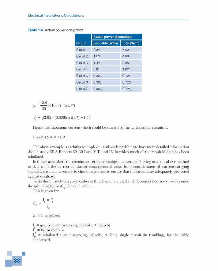
In the present case the various actual power dissipations per cable (Ib2R), calculated using the Ib
values given earlier and R values from Step 6, are given in Table 1.6. The total (W/m) values relate to the circuits and are the per cable values multiplied by 3 for three-phase circuits and by 2 for single-phase circuits.
The total cable power dissipation per metre is therefore 18.6 W/m; this is less than the thermal capacity of the trunking.
Electrical Installations Calculations
38
µ = × =18 636
100 51 7.
% . %
Fg = − × =3 95 0 0295 51 7 1 56. ( . . ) .
Hence the maximum current which could be carried by the light current circuits is:
1.56 × 4.9 A = 7.6 A
The above example is a relatively simple one and readers wishing to have more detailed information should study ERA Reports 69–30 Parts VIII and IX in which much of the required data has been tabulated.
In those cases where the circuits concerned are subject to overload, having used the above method to determine the correct conductor cross-sectional areas from consideration of current-carrying capacity, it is then necessary to check these areas to ensure that the circuits are adequately protected against overload.
To do this the methods given earlier in this chapter are used and it becomes necessary to determine the grouping factor (Cg) for each circuit.
This is given by:
CI F
Igg g
ta
=×
where, as before:
Ig = group current-carrying capacity, A (Step 6)
Fg = factor (Step 6)
Ita = tabulated current-carrying capacity, A for a single circuit (in trunking), for the cable concerned.
Table 1.6 Actual power dissipation
Circuit
Actual power dissipation
per cable (W/m) total (W/m)
Circuit l 2.34 7.02
Circuit 2 1.63 4.88
Circuit 3 1.44 2.88
Circuit 4 0.81 1.62
Circuit 5 0.363 0.726
Circuit 6 0.363 0.726
Circuit 7 0.363 0.726
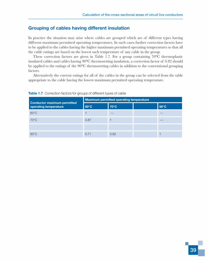
Calculation of the cross-sectional areas of circuit live conductors
39
Grouping of cables having different insulation
In practice the situation may arise where cables are grouped which are of different types having different maximum permitted operating temperatures. In such cases further correction factors have to be applied to the cables having the higher maximum permitted operating temperatures so that all the cable ratings are based on the lowest such temperature of any cable in the group.
These correction factors are given in Table 1.7. For a group containing 70°C thermoplastic insulated cables and cables having 90°C thermosetting insulation, a correction factor of 0.82 should be applied to the ratings of the 90°C thermosetting cables in addition to the conventional grouping factors.
Alternatively the current ratings for all of the cables in the group can be selected from the table appropriate to the cable having the lowest maximum permitted operating temperature.
Table 1.7 Correction factors for groups of different types of cable
Conductor maximum permitted operating temperature
Maximum permitted operating temperature
60°C 70°C 90°C
60°C 1 — —
70°C 0.87 1 —
90°C 0.71 0.82 1