Embed Size (px)
Citation preview
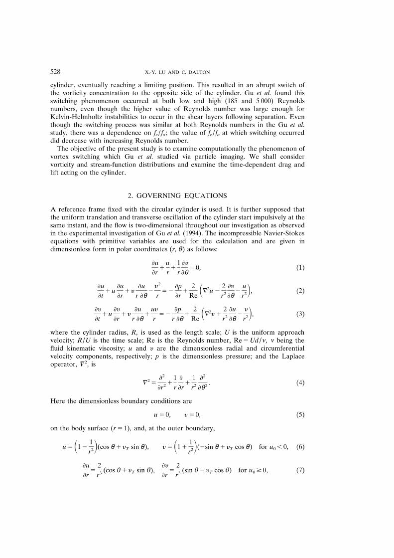
Journal of Fluids and Structures (1996) 10 , 527 – 541
CALCULATION OF THE TIMING OF VORTEX FORMATION FROM AN OSCILLATING CYLINDER
X . -Y . L U AND C . D ALTON
Department of Mechanical Engineering , Uni y ersity of Houston Houston , Texas 7 7 2 0 4 - 4 7 9 2 , U .S .A .
(Received 23 February 1996)
Vortex shedding from a transversely oscillating circular cylinder in a uniform flow is studied by numerical solutions of the two-dimensional unsteady Navier-Stokes equations with a primitive-variable formulation . As the frequency of excitation of the cylinder is increased relative to the inherent vortex formation frequency , the initially formed concentration of vorticity moves closer to the cylinder until a limiting position is reached ; at this point , the vorticity concentration abruptly switches to the opposite side of the cylinder . This process induces distinct changes of the topology of the corresponding streamline patterns . In addition , the influence of this vorticity-switching on forces acting on the cylinder is also investigated .
÷ 1996 Academic Press Limited
1 . INTRODUCTION
A RISER ON AN OFFSHORE PLATFORM in deep water can be subjected to currents of dif ferent magnitudes and directions at various elevations . Thus , a riser excited at one elevation due to vortex shedding oscillates at another elevation while exposed to the current at that elevation . Numerous investigators have recognized that the frequency of this forced oscillation can have dramatic ef fects on the vortex-shedding frequency of the oscillating cylinder . For example , a forced oscillation at or near the inherent vortex-shedding frequency , which is called the synchronization condition , produces a sharp change in the phase angle , f L , between the unsteady lift coef ficient , C L , and the cylinder displacement , y . This change occurs at f e / f o , 1 , where f e is the excitation frequency and f o is the vortex-shedding frequency from the stationary cylinder . In this range of f e / f o values , the amplitude of C L reaches a peak value . These variations in lift coef ficient amplitude and phase angle accompany a change in sign of the energy transfer between the cylinder and the fluid .
These observations are well known and have been documented by many inves- tigators , a few of whom are Grif fin (1971 , 1973) , Koopmann (1967) , Sarpkaya (1979) , Ongoren & Rockwell (1988a , b) and Pantazopoulos (1994) . A particular focus of these studies has been on the near wake with emphasis on excitation at or near the inherent vortex formation frequency , i . e ., synchronization . Williamson & Roshko (1988) found that there was an excitation frequency threshold at suf ficiently large oscillating amplitudes , beyond which the downstream vortex street experienced a basic change . Particle streaks provided a visualization of the flow and revealed the formation of vortex pairs during each half-cycle of the cylinder oscillation .
In a recent particle-imaging study of the timing of vortex formation from a circular cylinder which is undergoing forced transverse oscillations in a uniform approach flow , Gu et al . (1995) found some abrupt changes in flow topology . As f e / f o increased at a given amplitude and Reynolds number , the wake vorticity moved closer to the
0889 – 9746 / 96 / 050527 1 15 $18 . 00 ÷ 1996 Academic Press Limited
X . -Y . LU AND C . DALTON 528
cylinder , eventually reaching a limiting position . This resulted in an abrupt switch of the vorticity concentration to the opposite side of the cylinder . Gu et al . found this switching phenomenon occurred at both low and high (185 and 5 000) Reynolds numbers , even though the higher value of Reynolds number was large enough for Kelvin-Helmholtz instabilities to occur in the shear layers following separation . Even though the switching process was similar at both Reynolds numbers in the Gu et al . study , there was a dependence on f e / f o ; the value of f e / f o at which switching occurred did decrease with increasing Reynolds number .
The objective of the present study is to examine computationally the phenomenon of vortex switching which Gu et al . studied via particle imaging . We shall consider vorticity and stream-function distributions and examine the time-dependent drag and lift acting on the cylinder .
2 . GOVERNING EQUATIONS
A reference frame fixed with the circular cylinder is used . It is further supposed that the uniform translation and transverse oscillation of the cylinder start impulsively at the same instant , and the flow is two-dimensional throughout our investigation as observed in the experimental investigation of Gu et al . (1994) . The incompressible Navier-Stokes equations with primitive variables are used for the calculation and are given in dimensionless form in polar coordinates ( r , θ ) as follows :
u
r 1
u
r 1
1 r
y
θ 5 0 , (1)
u
t 1 u
u
r 1 y
u
r θ 2
y 2
r 5 2
p
r 1
2 Re
S = 2 u 2 2 r 2
y
θ 2
u
r 2 D , (2)
y
t 1 u
y
r 1 y
u
r θ 1
u y
r 5 2
p
r θ 1
2 Re
S = 2 y 1 2 r 2
u
θ 2
y
r 2 D , (3)
where the cylinder radius , R , is used as the length scale ; U is the uniform approach velocity ; R / U is the time scale ; Re is the Reynolds number , Re 5 Ud / … , … being the fluid kinematic viscosity ; u and y are the dimensionless radial and circumferential velocity components , respectively ; p is the dimensionless pressure ; and the Laplace operator , = 2 , is
= 2 5 2
r 2 1 1 r
r 1
1 r 2
2
θ 2 . (4)
Here the dimensionless boundary conditions are
u 5 0 , y 5 0 , (5)
on the body surface ( r 5 1) , and , at the outer boundary ,
u 5 S 1 2 1 r 2 D (cos θ 1 y T sin θ ) , y 5 S 1 1
1 r 2 D ( 2 sin θ 1 y T cos θ ) for u 0 , 0 , (6)
u
r 5
2 r 3 (cos θ 1 y T sin θ ) ,
y
r 5
2 r 3 (sin θ 2 y T cos θ ) for u 0 $ 0 , (7)
VORTEX FORMATION FROM OSCILLATING CYLINDER 529
where u 0 is the radial velocity normal to the outer boundary , and y T is given as
y T 5 d y e
d t (8)
and
y e 5 A e cos(2 π f e t ) , (9)
with A e and f e as the oscillating amplitude and frequency , respectively . In the circumferential direction , we use periodic boundary conditions .
3 . NUMERICAL METHOD
We consider the Navier-Stokes equations written in vector form ,
V t
5 2 = p 1 L ( V ) 1 N ( V ) , (10)
where V is the velocity vector and L ( V ) and N ( V ) represent the viscous terms and convective terms , respectively , i . e .,
L ( V ) 5 2
Re = 2 V , (11)
N ( V ) 5 2 ( V ? = ) V . (12)
Using the fractional-step method of Kim & Moin (1985) for the incompressible Navier-Stokes equations , the semi-discrete form can be obtained by splitting equation (10) into two substeps as
V ̂ 2 V n
D t 5 N D ( V ) 1 L D ( V ) , (13)
V n 1 1 2 V ̂ D t
5 2 = p n 1 1 , (14)
where V ̂ is the intermediate velocity , L D ( V ) and N D ( V ) respectively denote dif ference discretization forms for the terms of L ( V ) and N ( V ) . In the splitting method , it is required that the velocity field V n 1 1 satisfies the incompressibility constraint ,
= ? V n 1 1 5 0 . (15)
Incorporating the requirement from equation (15) into (14) , we finally arrive at a separately solvable elliptic equation for the pressure in the form
= 2 p n 1 1/2 5 1 D t
= ? V ̂ . (16)
To solve the elliptic equation given in equation (16) , a pressure boundary condition must be implemented . The pressure boundary condition may be taken as a key factor for solving the incompressible Navier-Stokes equations . According to a study on the pressure boundary conditions (Gresho & Sani 1987) , the condition is given as
p r
5 2 2
Re ( = 3 = 3 V ) ? n r , (17)
where n r indicates the unit vector in the radial direction .
X . -Y . LU AND C . DALTON 530
2
1
0
–1
–2
2
1
0
–1
–2
2
1
0
–1
–2
CL,
CD
CL,
CD
CL,
CD
(a)
(b)
(c)
0 50 100 150 200t
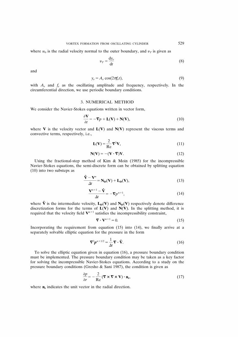
Figure 1 . Lift and drag coef ficients , C L and C D , for steady flow past cylinder at (a) Re 5 185 , (b) Re 5 500 , (c) Re 5 1000 : —— , C D ; - - - - , C L . In (a) , the average value of C D is C # D 5 1 ? 31 and the Strouhal number is
St 5 0 ? 195 ; in (b) , C # D 5 1 ? 22 , St 5 0 ? 222 ; in (c) , C # D 5 1 ? 21 , St 5 0 ? 224 .
In this study , a staggered grid , which is uniformly spaced in the circumferential direction and is exponentially stretched in the radial direction , is employed for the discretization of the governing equations . All the spatial derivatives are discretized using a second-order central dif ference scheme . The time derivative in equation (13) is solved using a second-order Adams-Bashforth scheme .
T ABLE 1 Experimental and calculated values for C # D and C L rms for
the nonoscillating cylinder
Experimental Calculated
Re C # D C L rms St C # D C L rms St
185 500
1 000
1 ? 28 1 ? 18 1 ? 15
— 0 ? 6 —
0 ? 19 0 ? 21 0 ? 22
1 ? 31 1 ? 22 1 ? 21
0 ? 422 0 ? 67 0 ? 78
0 ? 195 0 ? 222 0 ? 224
VORTEX FORMATION FROM OSCILLATING CYLINDER 531
2
1
0
–1
CL,
CD
0 50 100 150 200
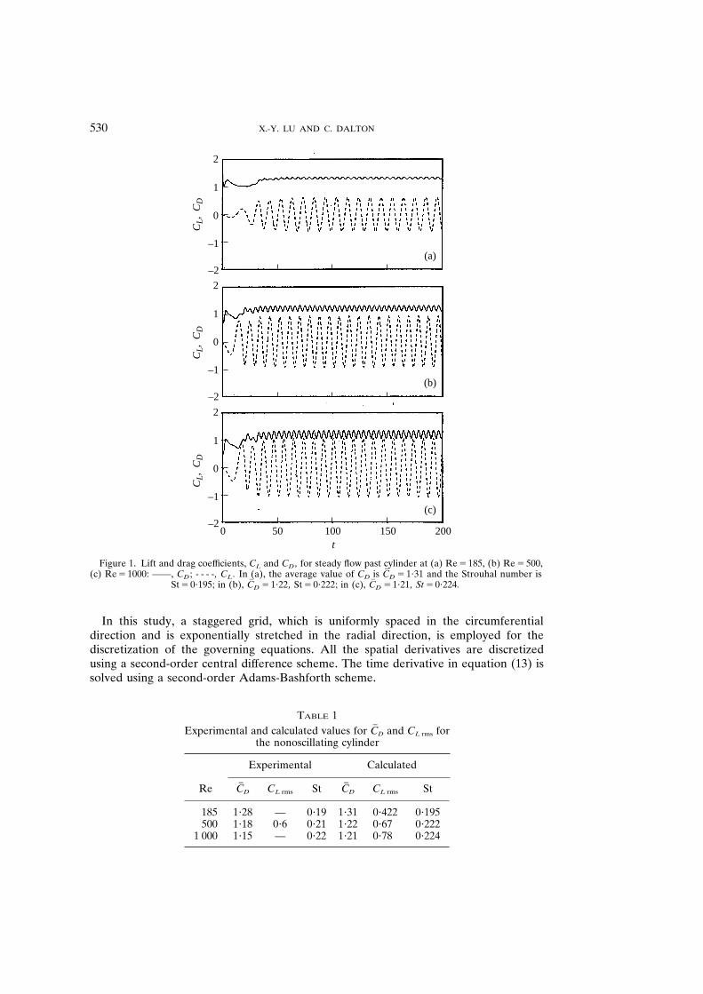
t Figure 2 . Lift and drag coef ficients for dif ferent grid resolutions and time steps for Re 5 185 , nonoscillating
case : —— , 256 3 128 , D t 5 0 ? 002 : C # D 5 1 ? 31 , C L rms 5 0 ? 430 , St 5 0 ? 195 ; - - - - , 512 3 256 , D t 5 0 ? 001 : C # D 5 1 ? 30 , C L rms 5 0 ? 422 , St 5 0 ? 192 .
The computational loop to advance the solution from one time level to the next consists of the following three substeps . First , the discretized equation (13) is advanced explicitly to obtain the new intermediate velocity using a second-order Adams- Bashforth scheme . Then , using the intermediate velocity from equation (13) , the pressure Poisson equation (16) is solved for the new pressure field . The last step is that equation (14) is solved for the new velocity .
2
1·5
1
0·5
0
–0·5
–1100 120 140 160 180 200
t
CL(256 128, dt = 0·002)CD(256 128, dt = 0·002)CL(512 256, dt = 0·001)CD(512 256, dt = 0·001)
CL,
CD
++++
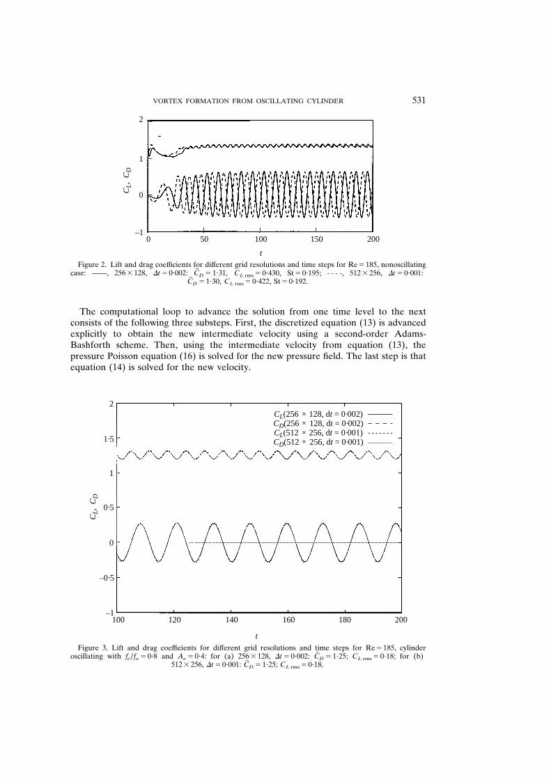
Figure 3 . Lift and drag coef ficients for dif ferent grid resolutions and time steps for Re 5 185 , cylinder oscillating with f e / f o 5 0 ? 8 and A e 5 0 ? 4 : for (a) 256 3 128 , D t 5 0 ? 002 : C # D 5 1 ? 25 ; C L rms 5 0 ? 18 ; for (b)
512 3 256 , D t 5 0 ? 001 : C # D 5 1 ? 25 ; C L rms 5 0 ? 18 .
X . -Y . LU AND C . DALTON 532
fe/fo = 0·8
1·5
1·0
0·5
0
–0·5
–1·00 60 120 180 240 300 360
θ(deg)
Cp
fe/fo = 0·9fe/fo = 1·0fe/fo = 1·12fe/fo = 1·2
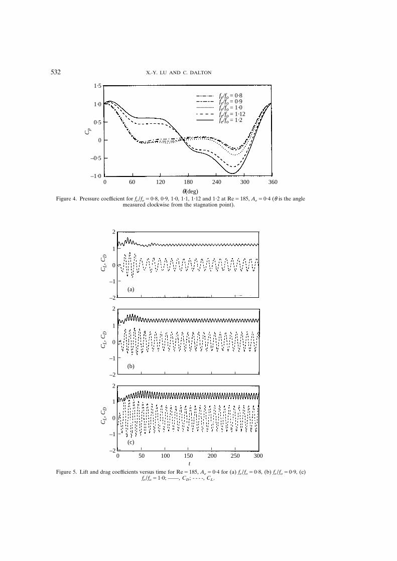
Figure 4 . Pressure coef ficient for f e / f o 5 0 ? 8 , 0 ? 9 , 1 ? 0 , 1 ? 1 , 1 ? 12 and 1 ? 2 at Re 5 185 , A e 5 0 ? 4 ( θ is the angle measured clockwise from the stagnation point) .
2
1
0
–1
–2
CL, C
D
(a)
0 50 100 150 200t
2
1
0
–1
–2
CL, C
D
(b)
2
1
0
–1
–2
CL, C
D
(c)
250 300
Figure 5 . Lift and drag coef ficients versus time for Re 5 185 , A e 5 0 ? 4 for (a) f e / f o 5 0 ? 8 , (b) f e / f o 5 0 ? 9 , (c) f e / f o 5 1 ? 0 ; —— , C D ; - - - - , C L .
VORTEX FORMATION FROM OSCILLATING CYLINDER 533
2
1
0
–1
–2
CL, C
D
(d)
0 50 100 150 200t
2
1
0
–1
–2
CL, C
D
(e)
2
1
0
–1
–2
CL, C
D
(f)
250 300
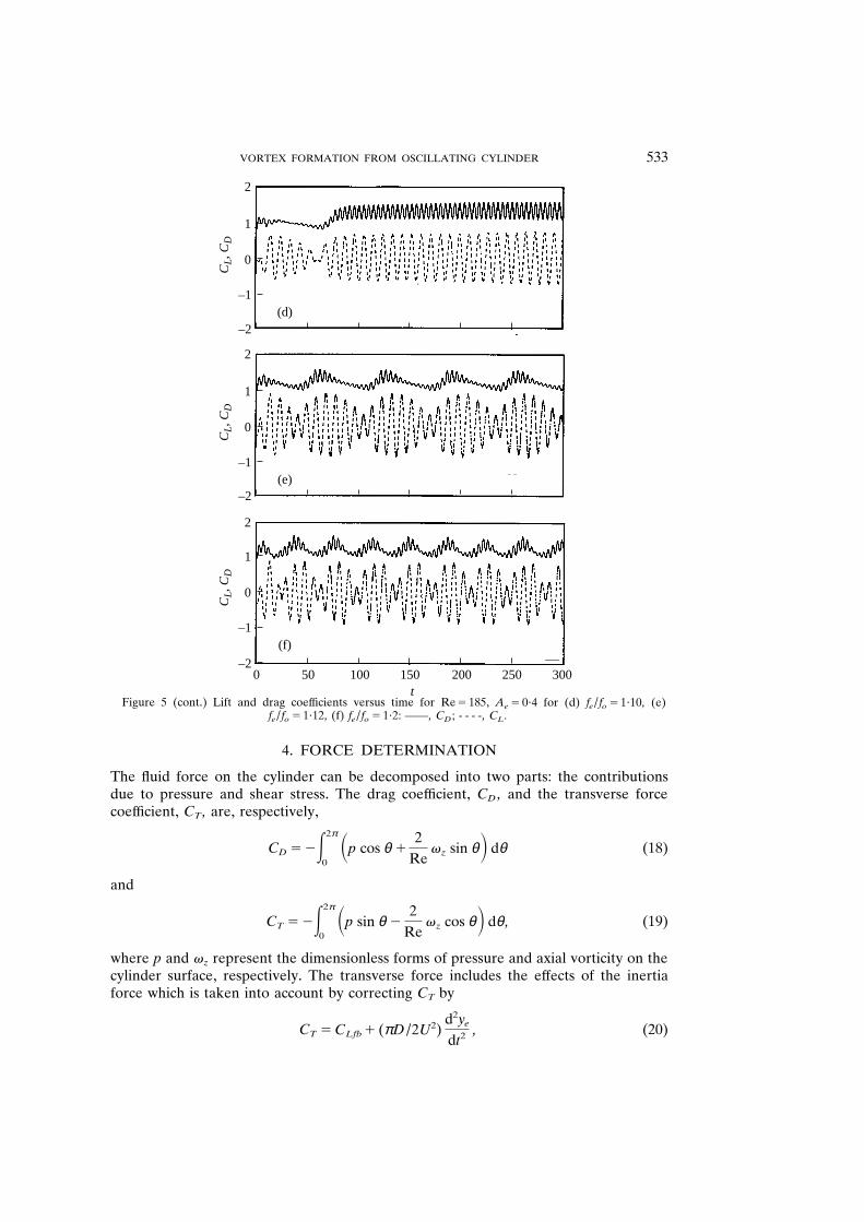
Figure 5 (cont . ) Lift and drag coef ficients versus time for Re 5 185 , A e 5 0 ? 4 for (d) f e / f o 5 1 ? 10 , (e) f e / f o 5 1 ? 12 , (f) f e / f o 5 1 ? 2 : —— , C D ; - - - - , C L .
4 . FORCE DETERMINATION
The fluid force on the cylinder can be decomposed into two parts : the contributions due to pressure and shear stress . The drag coef ficient , C D , and the transverse force coef ficient , C T , are , respectively ,
C D 5 2 E 2 π
0 S p cos θ 1
2 Re
v z sin θ D d θ (18)
and
C T 5 2 E 2 π
0 S p sin θ 2
2 Re
v z cos θ D d θ , (19)
where p and v z represent the dimensionless forms of pressure and axial vorticity on the cylinder surface , respectively . The transverse force includes the ef fects of the inertia force which is taken into account by correcting C T by
C T 5 C Lfb 1 ( π D / 2 U 2 ) d 2 y e
d t 2 , (20)
X . -Y . LU AND C . DALTON 534
fe/fo =1·1
fe/fo =0·9 fe/fo =1·12
fe/fo =1·0 fe/fo =1·2
fe/fo =0·8
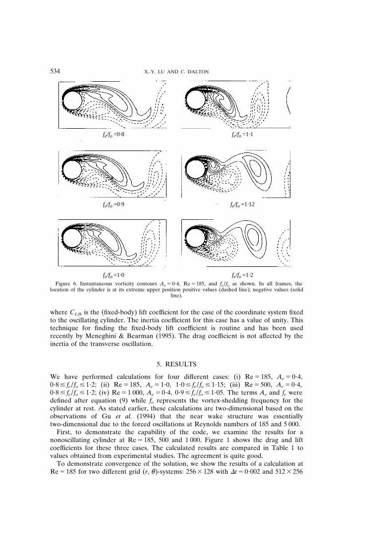
Figure 6 . Instantaneous vorticity contours A e 5 0 ? 4 , Re 5 185 , and f e / f o as shown . In all frames , the location of the cylinder is at its extreme upper position positive values (dashed line) ; negative values (solid
line) .
where C Lfb is the (fixed-body) lift coef ficient for the case of the coordinate system fixed to the oscillating cylinder . The inertia coef ficient for this case has a value of unity . This technique for finding the fixed-body lift coef ficient is routine and has been used recently by Meneghini & Bearman (1995) . The drag coef ficient is not af fected by the inertia of the transverse oscillation .
5 . RESULTS
We have performed calculations for four dif ferent cases : (i) Re 5 185 , A e 5 0 ? 4 , 0 ? 8 # f e / f o # 1 ? 2 ; (ii) Re 5 185 , A e 5 1 ? 0 , 1 ? 0 # f e / f o # 1 ? 15 ; (iii) Re 5 500 , A e 5 0 ? 4 , 0 ? 8 # f e / f o # 1 ? 2 ; (iv) Re 5 1 000 , A e 5 0 ? 4 , 0 ? 9 # f e / f o # 1 ? 05 . The terms A e and f e were defined after equation (9) while f o represents the vortex-shedding frequency for the cylinder at rest . As stated earlier , these calculations are two-dimensional based on the observations of Gu et al . (1994) that the near wake structure was essentially two-dimensional due to the forced oscillations at Reynolds numbers of 185 and 5 000 .
First , to demonstrate the capability of the code , we examine the results for a nonoscillating cylinder at Re 5 185 , 500 and 1 000 . Figure 1 shows the drag and lift coef ficients for these three cases . The calculated results are compared in Table 1 to values obtained from experimental studies . The agreement is quite good .
To demonstrate convergence of the solution , we show the results of a calculation at Re 5 185 for two dif ferent grid ( r , θ )-systems : 256 3 128 with D t 5 0 ? 002 and 512 3 256
VORTEX FORMATION FROM OSCILLATING CYLINDER 535
fe/fo =1·1
fe/fo =0·9 fe/fo =1·12
fe/fo =1·0 fe/fo =1·2
fe/fo =0·8
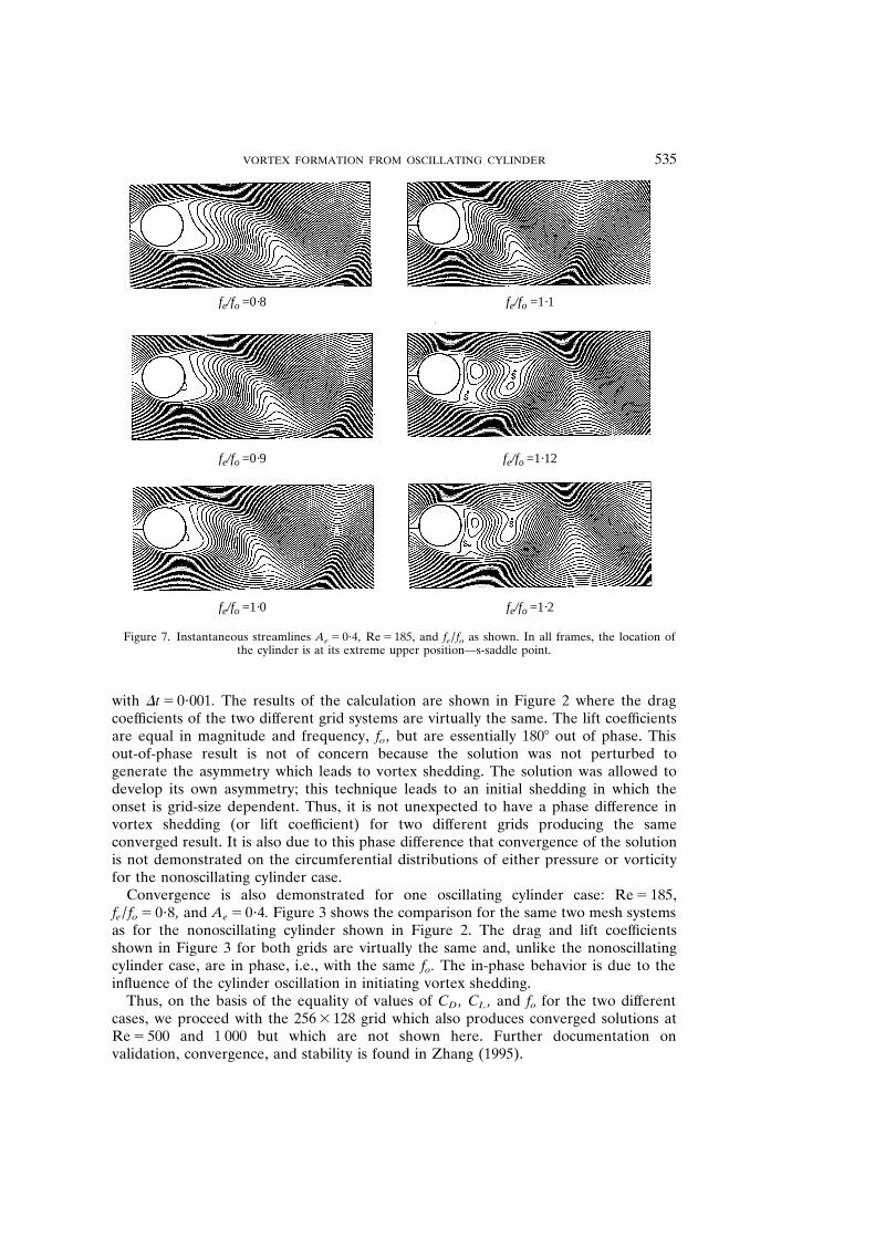
Figure 7 . Instantaneous streamlines A e 5 0 ? 4 , Re 5 185 , and f e / f o as shown . In all frames , the location of the cylinder is at its extreme upper position—s-saddle point .
with D t 5 0 ? 001 . The results of the calculation are shown in Figure 2 where the drag coef ficients of the two dif ferent grid systems are virtually the same . The lift coef ficients are equal in magnitude and frequency , f o , but are essentially 180 8 out of phase . This out-of-phase result is not of concern because the solution was not perturbed to generate the asymmetry which leads to vortex shedding . The solution was allowed to develop its own asymmetry ; this technique leads to an initial shedding in which the onset is grid-size dependent . Thus , it is not unexpected to have a phase dif ference in vortex shedding (or lift coef ficient) for two dif ferent grids producing the same converged result . It is also due to this phase dif ference that convergence of the solution is not demonstrated on the circumferential distributions of either pressure or vorticity for the nonoscillating cylinder case .
Convergence is also demonstrated for one oscillating cylinder case : Re 5 185 , f e / f o 5 0 ? 8 , and A e 5 0 ? 4 . Figure 3 shows the comparison for the same two mesh systems as for the nonoscillating cylinder shown in Figure 2 . The drag and lift coef ficients shown in Figure 3 for both grids are virtually the same and , unlike the nonoscillating cylinder case , are in phase , i . e ., with the same f o . The in-phase behavior is due to the influence of the cylinder oscillation in initiating vortex shedding .
Thus , on the basis of the equality of values of C D , C L , and f o for the two dif ferent cases , we proceed with the 256 3 128 grid which also produces converged solutions at Re 5 500 and 1 000 but which are not shown here . Further documentation on validation , convergence , and stability is found in Zhang (1995) .
X . -Y . LU AND C . DALTON 536
1·5
1·4
1·3
1·2
0·6
0·5
0·4
0·3
0·2
0·1
0
–0·1
–0·2
Tim
e-av
erag
e va
lue
of C
D
R.m
.s. v
alue
of C
LB
ase
pres
sure
0·7 0·8 0·9 1·0 1·1 1·2 1·3
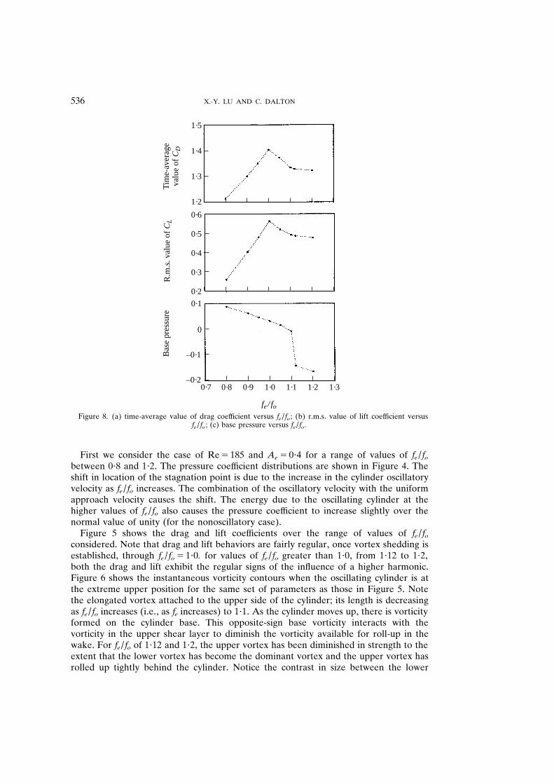
fe/ fo Figure 8 . (a) time-average value of drag coef ficient versus f e / f o ; (b) r . m . s . value of lift coef ficient versus
f e / f o ; (c) base pressure versus f e / f o .
First we consider the case of Re 5 185 and A e 5 0 ? 4 for a range of values of f e / f o between 0 ? 8 and 1 ? 2 . The pressure coef ficient distributions are shown in Figure 4 . The shift in location of the stagnation point is due to the increase in the cylinder oscillatory velocity as f e / f o increases . The combination of the oscillatory velocity with the uniform approach velocity causes the shift . The energy due to the oscillating cylinder at the higher values of f e / f o also causes the pressure coef ficient to increase slightly over the normal value of unity (for the nonoscillatory case) .
Figure 5 shows the drag and lift coef ficients over the range of values of f e / f o considered . Note that drag and lift behaviors are fairly regular , once vortex shedding is established , through f e / f o 5 1 ? 0 . for values of f e / f o greater than 1 ? 0 , from 1 ? 12 to 1 ? 2 , both the drag and lift exhibit the regular signs of the influence of a higher harmonic . Figure 6 shows the instantaneous vorticity contours when the oscillating cylinder is at the extreme upper position for the same set of parameters as those in Figure 5 . Note the elongated vortex attached to the upper side of the cylinder ; its length is decreasing as f e / f o increases (i . e ., as f e increases) to 1 ? 1 . As the cylinder moves up , there is vorticity formed on the cylinder base . This opposite-sign base vorticity interacts with the vorticity in the upper shear layer to diminish the vorticity available for roll-up in the wake . For f e / f o of 1 ? 12 and 1 ? 2 , the upper vortex has been diminished in strength to the extent that the lower vortex has become the dominant vortex and the upper vortex has rolled up tightly behind the cylinder . Notice the contrast in size between the lower
VORTEX FORMATION FROM OSCILLATING CYLINDER 537
fe/fo =1·0
fe/fo =1·05
fe/fo =1·1
fe/fo =1·15
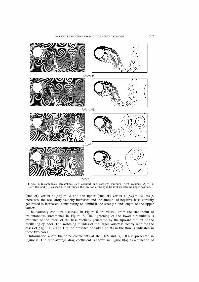
Figure 9 . Instantaneous streamlines (left column) and vorticity contours (right column) ; A e 5 1 ? 0 , Re 5 185 , and f e / f o as shown . In all frames , the location of the cylinder is at its extreme upper position .
(smaller) vortex at f e / f o 5 0 ? 8 and the upper (smaller) vortex at f e / f 0 5 1 ? 2 . As f e
increases , the oscillatory velocity increases and the amount of negative base vorticity generated is increased , contributing to diminish the strength and length of the upper vortex .
The vorticity contours discussed in Figure 6 are viewed from the standpoint of instantaneous streamlines in Figure 7 . The tightening of the lower streamlines is evidence of the ef fect of the base vorticity generated by the upward motion of the oscillating cylinder . The switching of sides of the larger vortex is clearly seen for the cases of f e / f o 5 1 ? 12 and 1 ? 2 ; the presence of saddle points in the flow is indicated in these two cases .
Information about the force coef ficients at Re 5 185 and A e 5 0 ? 4 is presented in Figure 8 . The time-average drag coef ficient is shown in Figure 8(a) as a function of
X . -Y . LU AND C . DALTON 538
fe/fo=0·8
fe/fo=0·9
fe/fo=0·95
fe/fo=1·0
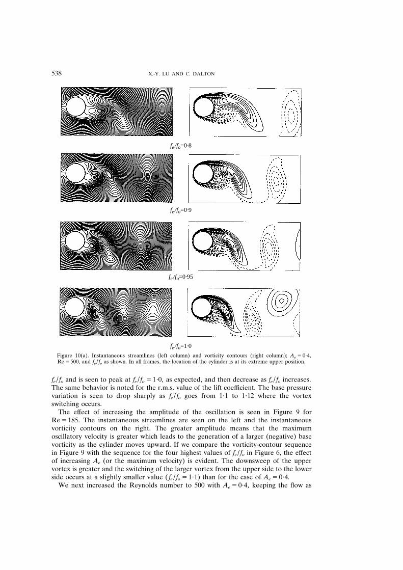
Figure 10(a) . Instantaneous streamlines (left column) and vorticity contours (right column) ; A e 5 0 ? 4 , Re 5 500 , and f e / f o as shown . In all frames , the location of the cylinder is at its extreme upper position .
f e / f o and is seen to peak at f e / f o 5 1 ? 0 , as expected , and then decrease as f e / f o increases . The same behavior is noted for the r . m . s . value of the lift coef ficient . The base pressure variation is seen to drop sharply as f e / f o goes from 1 ? 1 to 1 ? 12 where the vortex switching occurs .
The ef fect of increasing the amplitude of the oscillation is seen in Figure 9 for Re 5 185 . The instantaneous streamlines are seen on the left and the instantaneous vorticity contours on the right . The greater amplitude means that the maximum oscillatory velocity is greater which leads to the generation of a larger (negative) base vorticity as the cylinder moves upward . If we compare the vorticity-contour sequence in Figure 9 with the sequence for the four highest values of f e / f o in Figure 6 , the ef fect of increasing A e (or the maximum velocity) is evident . The downsweep of the upper vortex is greater and the switching of the larger vortex from the upper side to the lower side occurs at a slightly smaller value ( f e / f o 5 1 ? 1) than for the case of A e 5 0 ? 4 .
We next increased the Reynolds number to 500 with A e 5 0 ? 4 , keeping the flow as
VORTEX FORMATION FROM OSCILLATING CYLINDER 539
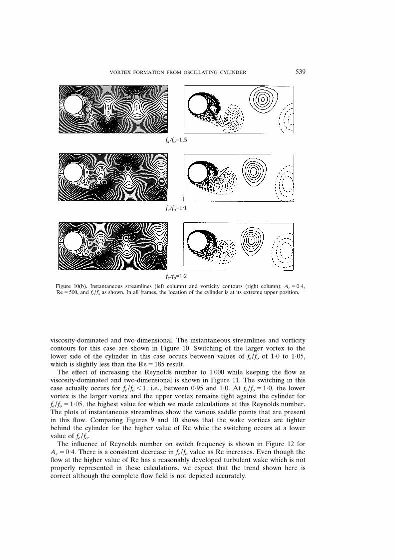
fe/fo=1‚5
fe/fo=1·1
fe/fo=1·2
Figure 10(b) . Instantaneous streamlines (left column) and vorticity contours (right column) ; A e 5 0 ? 4 , Re 5 500 , and f e / f o as shown . In all frames , the location of the cylinder is at its extreme upper position .
viscosity-dominated and two-dimensional . The instantaneous streamlines and vorticity contours for this case are shown in Figure 10 . Switching of the larger vortex to the lower side of the cylinder in this case occurs between values of f e / f o of 1 ? 0 to 1 ? 05 , which is slightly less than the Re 5 185 result .
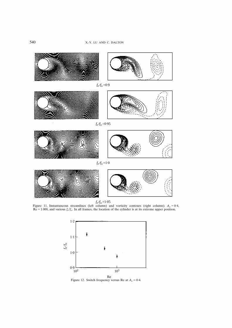
The ef fect of increasing the Reynolds number to 1 000 while keeping the flow as viscosity-dominated and two-dimensional is shown in Figure 11 . The switching in this case actually occurs for f e / f o , 1 , i . e ., between 0 ? 95 and 1 ? 0 . At f e / f o 5 1 ? 0 , the lower vortex is the larger vortex and the upper vortex remains tight against the cylinder for f e / f o 5 1 ? 05 , the highest value for which we made calculations at this Reynolds number . The plots of instantaneous streamlines show the various saddle points that are present in this flow . Comparing Figures 9 and 10 shows that the wake vortices are tighter behind the cylinder for the higher value of Re while the switching occurs at a lower value of f e / f o .
The influence of Reynolds number on switch frequency is shown in Figure 12 for A e 5 0 ? 4 . There is a consistent decrease in f e / f o value as Re increases . Even though the flow at the higher value of Re has a reasonably developed turbulent wake which is not properly represented in these calculations , we expect that the trend shown here is correct although the complete flow field is not depicted accurately .
X . -Y . LU AND C . DALTON 540
fe/fo =0·95
fe/fo =1·0
fe/fo =1·05
fe/fo =0·9
Figure 11 . Instantaneous streamlines (left column) and vorticity contours (right column) ; A e 5 0 ? 4 , Re 5 1 000 , and various f e / f o . In all frames , the location of the cylinder is at its extreme upper position .
1·2
1·1
1·0
0·9102 103
f e/f
o
Re Figure 12 . Switch frequency versus Re at A e 5 0 ? 4 .
VORTEX FORMATION FROM OSCILLATING CYLINDER 541
6 . CONCLUSIONS
These calculations support the contention of Gu et al . (1994) that the mechanism of vortex switching from one side of the cylinder to the other is the development to a high degree of concentration of vorticity in the wake of the approach flow to the cylinder . This concentration of vorticity involves the entire near wake and results in a tighter vortex structure as the f e / f o ratio increases . The ef fect of increasing the amplitude of oscillation at Re 5 185 is shown to lower the value of f e / f o at which vortex switching occurs . Similarly , increasing the Reynolds number to 500 and then to 1 000 at a given amplitude has the same ef fect ; the value of f e / f o at which switching occurs is decreased . A sharp change in base pressure is also noted as switching occurs at Re 5 185 .
ACKNOWLEDGMENTS
We are grateful to NSF for Grant ID INT924844 and to the Pittsburgh Supercomputing Center for Grant CBT91004P used in support of this project .
R EFERENCES
G RESHO , P . M . & S ANI , R . 1987 On pressure boundary conditions for the incompressible Navier-Stokes equations . International Journal for Numerical Methods in Fluids 7 , 1111 – 1145 .
G RIFFIN , O . M . 1971 The unsteady wake of an oscillating cylinder at low Reynolds number . Journal of Applied Mechanics 38 , 729 – 738 .
G RIFFIN , O . M . 1973 Instability in the vortex street wake of vibrating bluf f bodies . Journal of Fluids Engineering 95 , 569 – 581 .
G U , W ., C HYU , C . & R OCKWELL , D . 1994 Timing of vortex formation from an oscillating cylinder . Physics of Fluids 6 , 3677 – 3682 .
K IM , J . & M OIN , P . 1985 Application of a fractional-step method to incompressible Navier- Stokes equations . Journal of Computational Physics 59 , 308 – 323 .
K OOPMANN , G . H . 1967 The vortex wakes of vibrating cylinders at low Reynolds numbers . Journal of Fluid Mechanics 28 , 501 – 512 .
M ENEGHINI , J . R . & B EARMAN , P . W . 1995 Numerical simulation of high amplitude oscillatory flow about a circular cylinder . Journal of Fluids and Structures 9 , 435 – 455 .
O NGOREN , A . & R OCKWELL , D . 1988a Flow structure from an oscillating cylinder . Part 1 : Mechanisms of phase shift and recovery of the near wake . Journal of Fluid Mechanics 191 , 197 – 223 .
O NGOREN , A . & R OCKWELL , D . 1988b Flow structure from an oscillating cylinder . Part 2 : Mode computation in the near wake . Journal of Fluid Mechanics 191 , 225 – 245 .
P ANTAZOPOULOS , M . S . 1994 Vortex-induced vibration parameters : a critical review . In Proceedings International Conference on Of fshore Mechanics and Arctic Engineering , Houston , TX , U . S . A . Vol . 1 , pp . 199 – 255 .
S ARPKAYA , T . 1979 Vortex-induced oscillations—a selective review . Journal of Applied Mechanics 46 , 241 – 258 .
W ILLIAMSON , C . H . K . & R OSHKO , A . 1988 . Vortex formation in the wake of an oscillating cylinder . Journal of Fluids and Structures 2 , 355 – 381 .
Z HANG , J . -F . 1995 . A numerical study of three-dimensional unsteady flows past a circular cylinder , Ph . D . dissertation , University of Houston , Houston , Texas , U . S . A .