Embed Size (px)
Citation preview
Job Number 08-015H
Volume/Sheet No. of
Client/Contract Tt/Robles Diversion
Phase/Subject Tainter Gate Analysis
Design Topic Loading Conditions
Made By PRC/VRG Date 12/17/2008 Checked By EGL Date 2/13/2009 Page No.
Task: Input
Information
Determine the environmental loads and loading combinations for the analysis of the existing tainter gates. Important
Notes:
1. Environmental loads and load combinations based on EM 1110-2-2702, Design of Spillway Tainter Gates, USACE, 1 January 2000.
2. Structural steel is Federal Specification Q-S-741, type II or ASTM Designation A7 (Original Construction Specifications)
3. Site seismicity provided in Table 2 of the Ground Motion Hazard Evaluation for Robles Diversion Dam Modification Project , by AMEC Geomatrix, Inc. Oakland, CA, dated November 12, 2008.
4. OBE - 50% probability of exceedence during the service life. This corresponds to a return period of 144 years for a project with a service life of 100 years. [ER 1110-2-1806]
Calculations:
Loads
Gravity
Selfweight D 6.25 k Determined by the finite element modeling.
Mud Weight M 0.94 k Based on future silt loading from removal of the Matilija Dam (top of girders filled with silt).
No. Girders 6
Girder Length 14.58 ft d 8 bf 4
γm 125 pcf tw 0.27 tf 0.425
Gate Length 16 ft
Ice Weight C 0.34 k Iced surface is one side of skin plate, top of girders, and downstream face of girders.
Iced surface area 288 sf
Skin Plate 152 sf Ice thickness 0.25 in
Girders 136 sf γice 56 pcf
Hydrostatic
Max that will ever occur H1 11.50 ft Calculate hydrostatic pressure on the skin plate based on depth of water.
Design (10-yr return period) H2 11.50 ft Use H1, river is flashy.
Normal (50% annual exceedance) H3 11.50 ft Use H1, river is flashy.
Existing Sill 755.50 ft Dam Raise 2.00 ft γw 62.5 pcf
Existing Crest 765.00 ft New Crest 767.00 ft
Machinery
Max Downward Q1 0.00 k Wire rope hoist system.
At-Rest Downward Q2 0.00 k Wire rope hoist system.
Max Upward Q3 7.50 k Design drawing 40-D-4331, Radial Gate Hoist, Capacity - 7500 Pounds, Assembly - List of Parts.
0.11 k/in Contact pressure due to wire rope on gate end girders under gate jammed condition
Ice Impact I 0.00 klf Inflow hydrographs show that the reservoir does not sustain a WSEL sufficiently long to establish icing; collaborated by CMWD Staff.
Workbook: Tainter Gates
Worksheet: Loading and DCRs 1
2/13/2009
10:05 AM
1
Job Number 08-015H
Volume/Sheet No. of
Client/Contract Tt/Robles Diversion
Phase/Subject Tainter Gate Analysis
Design Topic Loading Conditions
Made By PRC/VRG Date 12/17/2008 Checked By EGL Date 2/13/2009 Page No.
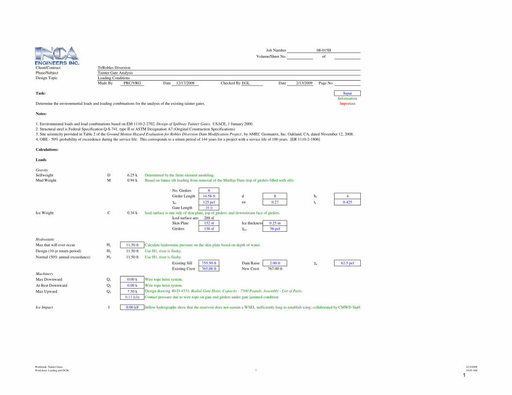
Side Seal Friction Fs 0.33 k Eqn. 3-2, EM 2702.
µs 0.5 d 3.50 in
l 12.13 ft h 11.50 ft
l1 12.13 ft δ 0.25 in
l2 0.00 ft E 900 psi sealsunlimited.com
S 0.83 plf I 0.00439 in^3
γw 62.5 pcf
Trunnion Pin Friction Ft 0.30 EM 2702
Earthquake E 0.318 g When gate is open - OBE applied to selfweight, mud and ice.
When gate is closed - disregard inertial forces, use hydrodynamic pressure.
Elevation y p
767.00 ft 0.00 ft 0.00 psf
766.00 ft 1.00 ft 58.97 psf
765.00 ft 2.00 ft 83.40 psf
764.00 ft 3.00 ft 102.15 psf
763.00 ft 4.00 ft 117.95 psf
762.00 ft 5.00 ft 131.87 psf
761.00 ft 6.00 ft 144.46 psf
760.00 ft 7.00 ft 156.03 psf
759.00 ft 8.00 ft 166.81 psf
758.00 ft 9.00 ft 176.92 psf
757.00 ft 10.00 ft 186.49 psf
756.00 ft 11.00 ft 195.60 psf
755.50 ft 11.50 ft 199.99 psf
Wave WA 0.00 ft
Wind W 3.73 k ASCE 7-05, Paragraph 6.5.10
qh 17 psf As 184 sf
G 0.85 I 1.15
Cf 1.4 V 85 mph
Workbook: Tainter Gates
Worksheet: Loading and DCRs 2
2/13/2009
10:05 AM
2
Job Number 08-015H
Volume/Sheet No. of
Client/Contract Tt/Robles Diversion
Phase/Subject Tainter Gate Analysis
Design Topic Loading Conditions
Made By PRC/VRG Date 12/17/2008 Checked By EGL Date 2/13/2009 Page No.
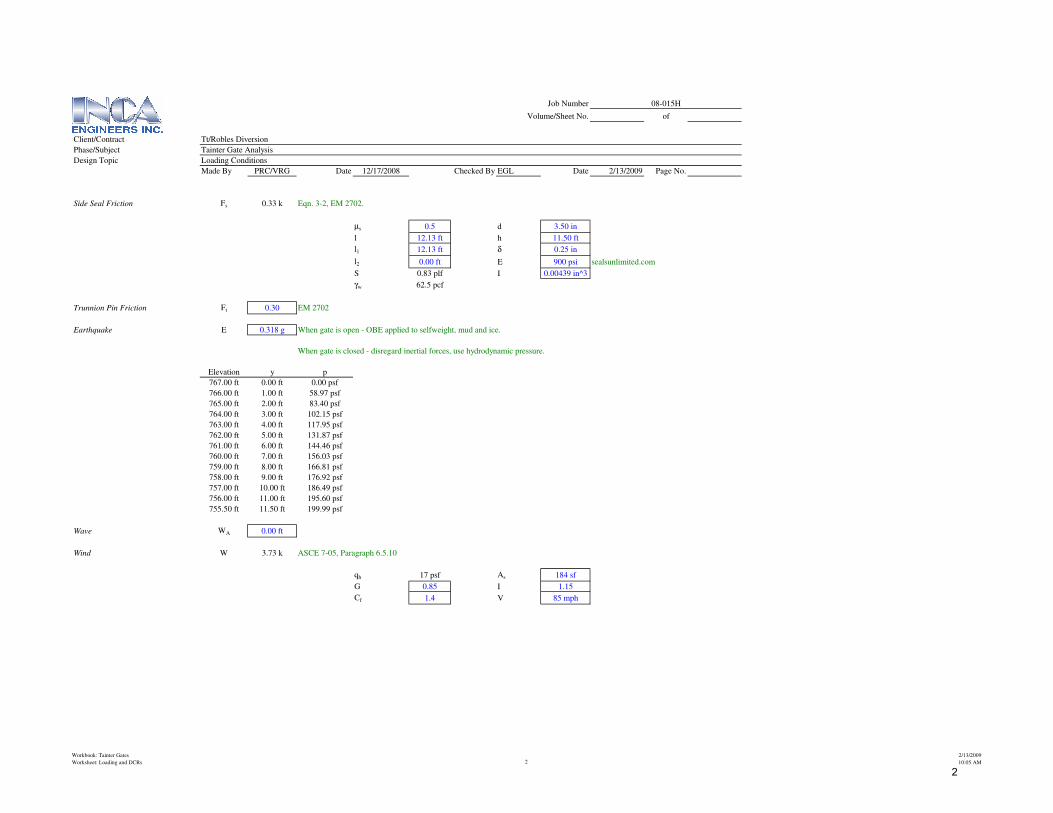
Selfweight Mud Ice Hydrostatic Hydrostatic Hydrostatic Downward Downward Upward Impact Friction Friction Earthquake Wave Wind
Load Cases D M C H1 H2 H3 Q1 Q2 Q3 I Fs Ft E WA W
LC 1 - Gate Closed
Eqn 3-5 1.2 1.6 1.6 1.4 1.2 Extreme Pool
Eqn 3-6A 1.2 1.6 1.6 1.4 1.2 Operating Pool
Eqn 3-6 B 1.2 1.6 1.6 1.4 1.2 1.2 Operating Pool
Eqn 3-6 C 1.2 1.6 1.6 1.4 1.2 kI Operating Pool
Eqn 3-7 1.2 1.6 1.6 1.2 1.0 Earthquake
LC 2 - Gate Operating with 2 Hoists
Eqn 3-8 1.2 1.6 1.6 1.4 1.4 1.0 Extreme Pool
Eqn 3-9 A 1.2 1.6 1.6 1.4 1.4 1.0 1.2 Operating Pool
Eqn 3-9 B 1.2 1.6 1.6 1.4 kI 1.4 1.0 Operating Pool
LC 3 - Gate Operating with 1 Hoist
Eqn 3-10 1.2 1.6 1.6 1.4 1.4 1.0
LC 4 - Gate Jammed
Eqn 3-11 A 1.2 1.6 1.6 1.4 1.2
Eqn 3-11 B 1.2 1.6 1.6 1.4 1.2
LC 5 - Gate Fully Opened
Eqn 3-12 A kd 1.6 1.6 1.3
Eqn 3-12 B kd 1.6 1.6 1.0
Eqn 3-12 C kd 1.6 1.6 1.2
Gate Opening 0.00 ft
Tributary
Girder G-G Spacing Girder El. Midheight Height Note
Top El. 767.00 ft Existing Gate Extended by 2ft
2.00 ft 766.00 ft
A 765.00 ft 3.05 ft Sheet 767-D-252, 16'-0" x 9'-0" and 10'-0" x 9'-6" Radial Gates
2.10 ft 763.95 ft
B 762.90 ft 1.95 ft Sheet 767-D-252, 16'-0" x 9'-0" and 10'-0" x 9'-6" Radial Gates
1.81 ft 762.00 ft
C 761.09 ft 1.69 ft Sheet 767-D-252, 16'-0" x 9'-0" and 10'-0" x 9'-6" Radial Gates
1.57 ft 760.31 ft
D 759.52 ft 1.48 ft Sheet 767-D-252, 16'-0" x 9'-0" and 10'-0" x 9'-6" Radial Gates
1.38 ft 758.83 ft
E 758.14 ft 1.28 ft Sheet 767-D-252, 16'-0" x 9'-0" and 10'-0" x 9'-6" Radial Gates
1.19 ft 757.55 ft
F 756.96 ft 1.13 ft Sheet 767-D-252, 16'-0" x 9'-0" and 10'-0" x 9'-6" Radial Gates
1.08 ft 756.42 ft
G 755.88 ft 0.73 ft Sheet 767-D-252, 16'-0" x 9'-0" and 10'-0" x 9'-6" Radial Gates
0.38 ft 755.69 ft
Bottom 755.50 ft 0.19 ft Sheet 767-D-252, 16'-0" x 9'-0" and 10'-0" x 9'-6" Radial Gates
Workbook: Tainter Gates
Worksheet: Loading and DCRs 3
2/13/2009
10:05 AM
3
Job Number 08-015H
Volume/Sheet No. of
Client/Contract Tt/Robles Diversion
Phase/Subject Tainter Gate Analysis
Design Topic Loading Conditions
Made By PRC/VRG Date 12/17/2008 Checked By EGL Date 2/13/2009 Page No.
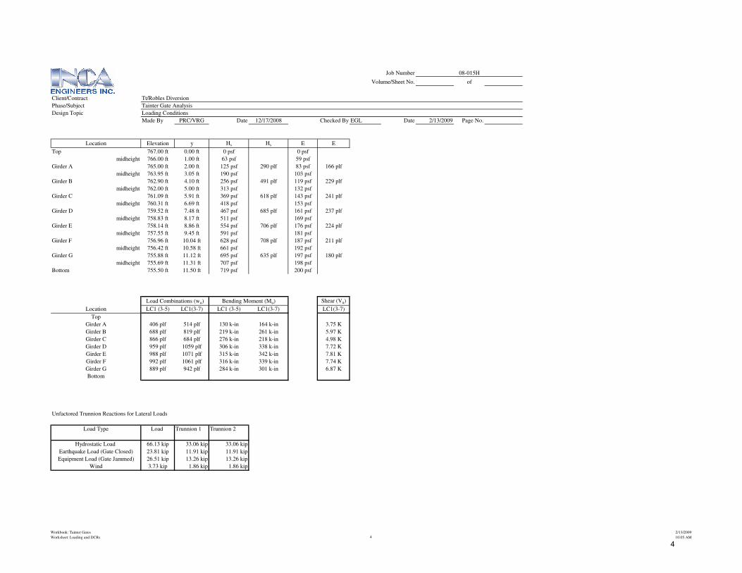
Location Elevation y Hs Hs E E
Top 767.00 ft 0.00 ft 0 psf 0 psf
midheight 766.00 ft 1.00 ft 63 psf 59 psf
Girder A 765.00 ft 2.00 ft 125 psf 290 plf 83 psf 166 plf
midheight 763.95 ft 3.05 ft 190 psf 103 psf
Girder B 762.90 ft 4.10 ft 256 psf 491 plf 119 psf 229 plf
midheight 762.00 ft 5.00 ft 313 psf 132 psf
Girder C 761.09 ft 5.91 ft 369 psf 618 plf 143 psf 241 plf
midheight 760.31 ft 6.69 ft 418 psf 153 psf
Girder D 759.52 ft 7.48 ft 467 psf 685 plf 161 psf 237 plf
midheight 758.83 ft 8.17 ft 511 psf 169 psf
Girder E 758.14 ft 8.86 ft 554 psf 706 plf 176 psf 224 plf
midheight 757.55 ft 9.45 ft 591 psf 181 psf
Girder F 756.96 ft 10.04 ft 628 psf 708 plf 187 psf 211 plf
midheight 756.42 ft 10.58 ft 661 psf 192 psf
Girder G 755.88 ft 11.12 ft 695 psf 635 plf 197 psf 180 plf
midheight 755.69 ft 11.31 ft 707 psf 198 psf
Bottom 755.50 ft 11.50 ft 719 psf 200 psf
Shear (Vu)
Location LC1 (3-5) LC1(3-7) LC1 (3-5) LC1(3-7) LC1(3-7)
Top
Girder A 406 plf 514 plf 130 k-in 164 k-in 3.75 K
Girder B 688 plf 819 plf 219 k-in 261 k-in 5.97 K
Girder C 866 plf 684 plf 276 k-in 218 k-in 4.98 K
Girder D 959 plf 1059 plf 306 k-in 338 k-in 7.72 K
Girder E 988 plf 1071 plf 315 k-in 342 k-in 7.81 K
Girder F 992 plf 1061 plf 316 k-in 339 k-in 7.74 K
Girder G 889 plf 942 plf 284 k-in 301 k-in 6.87 K
Bottom
Unfactored Trunnion Reactions for Lateral Loads
Load Type Load Trunnion 1 Trunnion 2
Hydrostatic Load 66.13 kip 33.06 kip 33.06 kip
Earthquake Load (Gate Closed) 23.81 kip 11.91 kip 11.91 kip
Equipment Load (Gate Jammed) 26.51 kip 13.26 kip 13.26 kip
Wind 3.73 kip 1.86 kip 1.86 kip
Load Combinations (wu) Bending Moment (Mu)
Workbook: Tainter Gates
Worksheet: Loading and DCRs 4
2/13/2009
10:05 AM
4
References
(1) Crane Handbook by Whiting Corporation
(2) CMAA 70, 2004
(3) Drawings Provided by CESPL
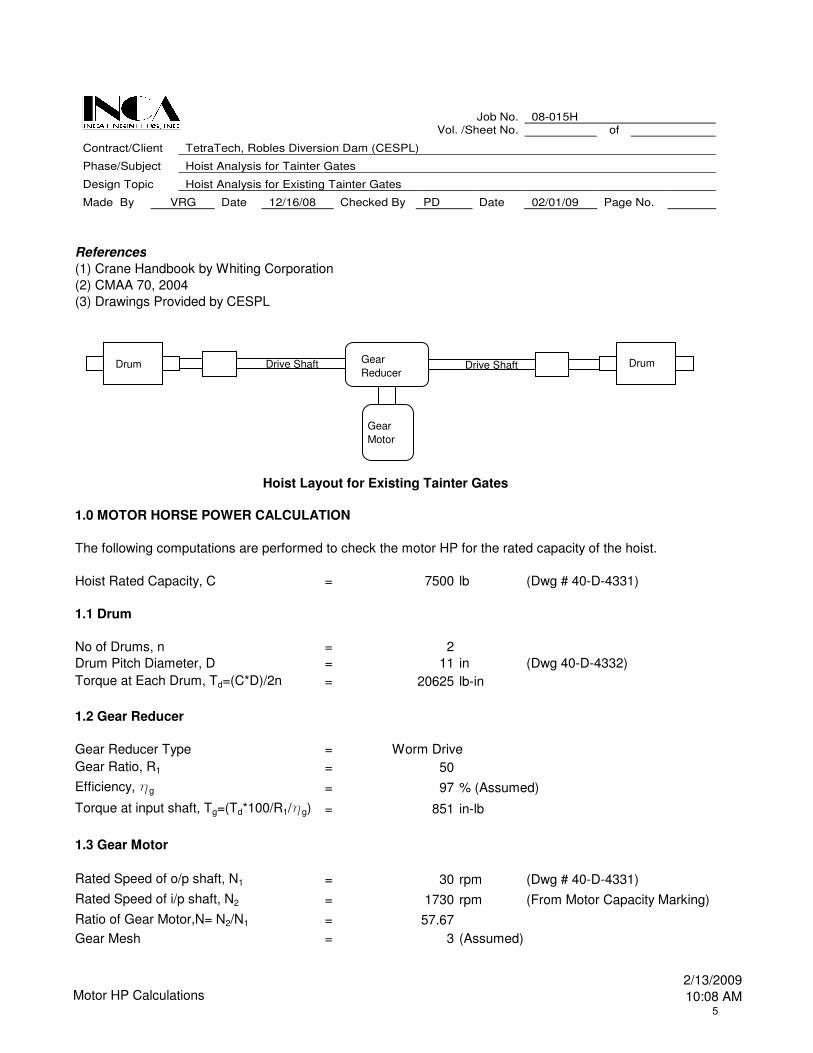
1.0 MOTOR HORSE POWER CALCULATION
Hoist Rated Capacity, C = 7500 lb (Dwg # 40-D-4331)
1.1 Drum
No of Drums, n = 2
Drum Pitch Diameter, D = 11 in (Dwg 40-D-4332)
Torque at Each Drum, Td=(C*D)/2n = 20625 lb-in
1.2 Gear Reducer
Gear Reducer Type = Worm Drive
Gear Ratio, R1 = 50
Efficiency, hg = 97 % (Assumed)
Torque at input shaft, Tg=(Td*100/R1/hg) = 851 in-lb
1.3 Gear Motor
Rated Speed of o/p shaft, N1 = 30 rpm (Dwg # 40-D-4331)
Rated Speed of i/p shaft, N2 = 1730 rpm (From Motor Capacity Marking)
Ratio of Gear Motor,N= N2/N1 = 57.67
Gear Mesh = 3 (Assumed)
The following computations are performed to check the motor HP for the rated capacity of the hoist.
Job No. 08-015H Vol. /Sheet No. of
Contract/Client TetraTech, Robles Diversion Dam (CESPL)
Phase/Subject Hoist Analysis for Tainter Gates
Design Topic Hoist Analysis for Existing Tainter Gates
Made By VRG Date 12/16/08 Checked By PD Date 02/01/09 Page No.
Gear
Motor
Gear
ReducerDrive Shaft Drive ShaftDrum Drum
Hoist Layout for Existing Tainter Gates
Motor HP Calculations2/13/2009
10:08 AM5
Job No. 08-015H Vol. /Sheet No. of
Contract/Client TetraTech, Robles Diversion Dam (CESPL)
Phase/Subject Hoist Analysis for Tainter Gates
Design Topic Hoist Analysis for Existing Tainter Gates
Made By VRG Date 12/16/08 Checked By PD Date 02/01/09 Page No.
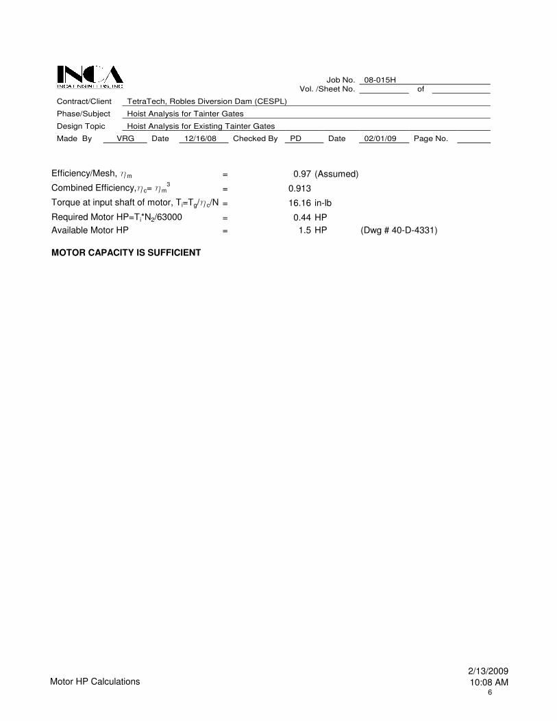
Efficiency/Mesh, hm = 0.97 (Assumed)
Combined Efficiency,hc= hm3
= 0.913
Torque at input shaft of motor, Ti=Tg/hc/N = 16.16 in-lb
Required Motor HP=Ti*N2/63000 = 0.44 HP
Available Motor HP = 1.5 HP (Dwg # 40-D-4331)
MOTOR CAPACITY IS SUFFICIENT
Motor HP Calculations2/13/2009
10:08 AM6
References
(1) Crane Handbook by Whiting Corporation
(2) Drawings Provided by CESPL
(3) CMAA 70, 2004
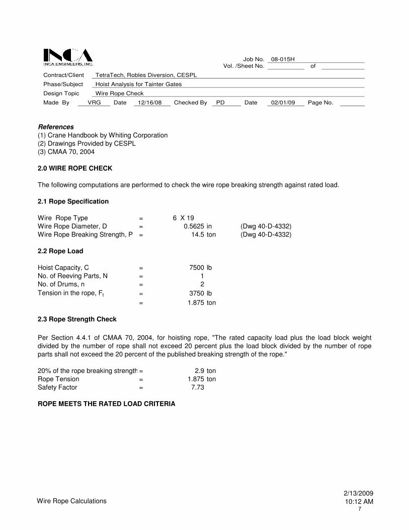
2.0 WIRE ROPE CHECK
The following computations are performed to check the wire rope breaking strength against rated load.
2.1 Rope Specification
Wire Rope Type = 6 X 19
Wire Rope Diameter, D = 0.5625 in (Dwg 40-D-4332)
Wire Rope Breaking Strength, P = 14.5 ton (Dwg 40-D-4332)
2.2 Rope Load
Hoist Capacity, C = 7500 lb
No. of Reeving Parts, N = 1
No. of Drums, n = 2
Tension in the rope, Ft = 3750 lb
= 1.875 ton
2.3 Rope Strength Check
20% of the rope breaking strength = 2.9 ton
Rope Tension = 1.875 ton
Safety Factor = 7.73
ROPE MEETS THE RATED LOAD CRITERIA
Per Section 4.4.1 of CMAA 70, 2004, for hoisting rope, "The rated capacity load plus the load block weight
divided by the number of rope shall not exceed 20 percent plus the load block divided by the number of rope
parts shall not exceed the 20 percent of the published breaking strength of the rope."
Job No. 08-015H Vol. /Sheet No. of
Contract/Client TetraTech, Robles Diversion, CESPL
Phase/Subject Hoist Analysis for Tainter Gates
Design Topic Wire Rope Check
Made By VRG Date 12/16/08 Checked By PD Date 02/01/09 Page No.
Wire Rope Calculations2/13/2009
10:12 AM7
References
(1) Drawings Provided by CESPL, Dwg # 40-D-4332
(2) CMAA 70, 2004
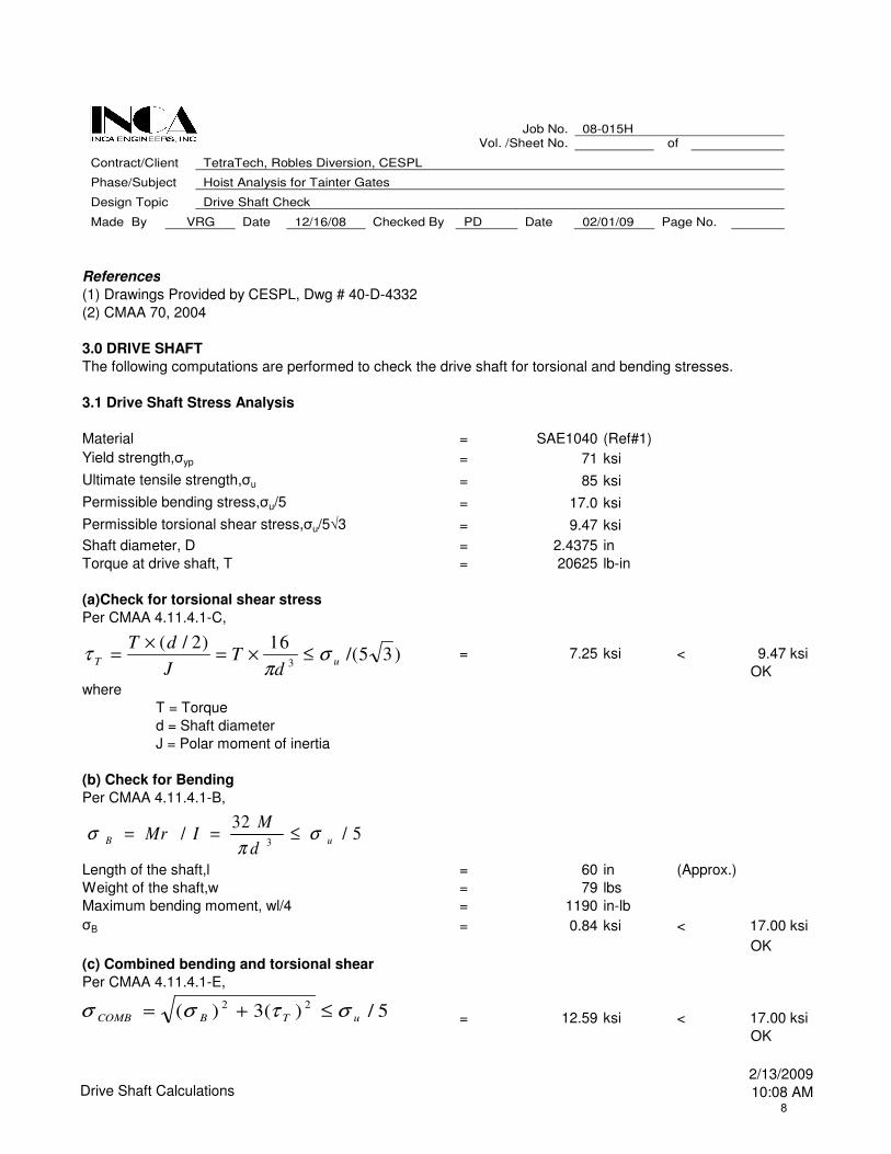
3.0 DRIVE SHAFT
The following computations are performed to check the drive shaft for torsional and bending stresses.
3.1 Drive Shaft Stress Analysis
Material = SAE1040 (Ref#1)
Yield strength,σyp = 71 ksi
Ultimate tensile strength,σu = 85 ksi
Permissible bending stress,σu/5 = 17.0 ksi
Permissible torsional shear stress,σu/5√3 = 9.47 ksi
Shaft diameter, D = 2.4375 in
Torque at drive shaft, T = 20625 lb-in
(a)Check for torsional shear stress
Per CMAA 4.11.4.1-C,
= 7.25 ksi < 9.47 ksi
OK
where
T = Torque
d = Shaft diameter
J = Polar moment of inertia
(b) Check for Bending
Per CMAA 4.11.4.1-B,
Length of the shaft,l = 60 in (Approx.)
Weight of the shaft,w = 79 lbs
Maximum bending moment, wl/4 = 1190 in-lb
σB = 0.84 ksi < 17.00 ksi
OK
(c) Combined bending and torsional shear
Per CMAA 4.11.4.1-E,
= 12.59 ksi < 17.00 ksi
OK
Job No. 08-015H Vol. /Sheet No. of
Contract/Client TetraTech, Robles Diversion, CESPL
Phase/Subject Hoist Analysis for Tainter Gates
Design Topic Drive Shaft Check
Made By VRG Date 12/16/08 Checked By PD Date 02/01/09 Page No.
)35/(16)2/(
3 uTd
TJ
dTσ
πτ ≤×=
×=
5/32
/3 uB
d
MIMr σ
πσ ≤==
5/)(3)( 22
uTBCOMB στσσ ≤+=
Drive Shaft Calculations2/13/2009
10:08 AM8
References
(1) Crane Handbook by Whiting Corporation
(2) CMAA 70, 2004
(3) Drawings Provided by CESPL
(4) EM 1110-2-2702, Design of Spillway Tainter Gates
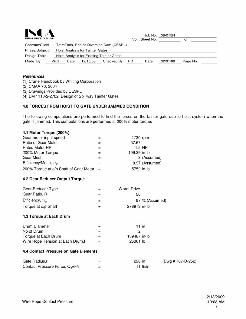
4.0 FORCES FROM HOIST TO GATE UNDER JAMMED CONDITION
Gear motor input speed = 1730 rpm
Ratio of Gear Motor = 57.67
Rated Motor HP = 1.5 HP
200% Motor Torque = 109.29 in-lb
Gear Mesh = 3 (Assumed)
Efficiency/Mesh, hm = 0.97 (Assumed)
200% Torque at o/p Shaft of Gear Motor = 5752 in-lb
4.2 Gear Reducer Output Torque
Gear Reducer Type = Worm Drive
Gear Ratio, R1 = 50
Efficiency, hg = 97 % (Assumed)
Torque at o/p Shaft = 278973 in-lb
4.3 Torque at Each Drum
Drum Diameter = 11 in
No of Drum = 2
Torque at Each Drum = 139487 in-lb
Wire Rope Tension at Each Drum,F = 25361 lb
4.4 Contact Pressure on Gate Elements
Gate Radius,r = 228 in (Dwg # 767-D-252)
Contact Pressure Force, Q3=F/r = 111 lb/in
The following computations are performed to find the forces on the tainter gate due to hoist system when the
gate is jammed. This computations are performed at 200% motor torque.
4.1 Motor Torque (200%)
Job No. 08-015H Vol. /Sheet No. of
Contract/Client TetraTech, Robles Diversion Dam (CESPL)
Phase/Subject Hoist Analysis for Tainter Gates
Design Topic Hoist Analysis for Existing Tainter Gates
Made By VRG Date 12/16/08 Checked By PD Date 02/01/09 Page No.
Wire Rope Contact Pressure2/13/2009
10:08 AM9
References
(1) EM 1110-2-2702, Design of Spillway Tainter Gates
(2) Drawings Provided by CESPL
(3) SAP 2000 Analysis Results for Existing Tainter Gates
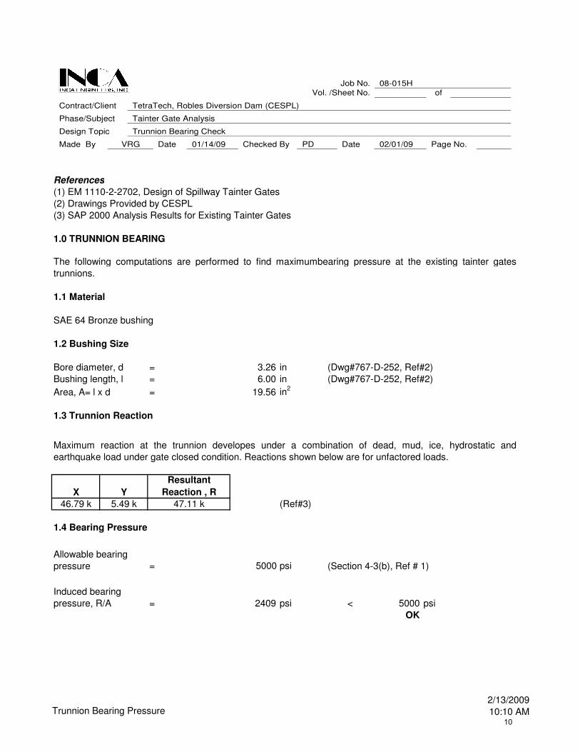
1.0 TRUNNION BEARING
1.1 Material
SAE 64 Bronze bushing
1.2 Bushing Size
Bore diameter, d = 3.26 in (Dwg#767-D-252, Ref#2)
Bushing length, l = 6.00 in (Dwg#767-D-252, Ref#2)
Area, A= l x d = 19.56 in2
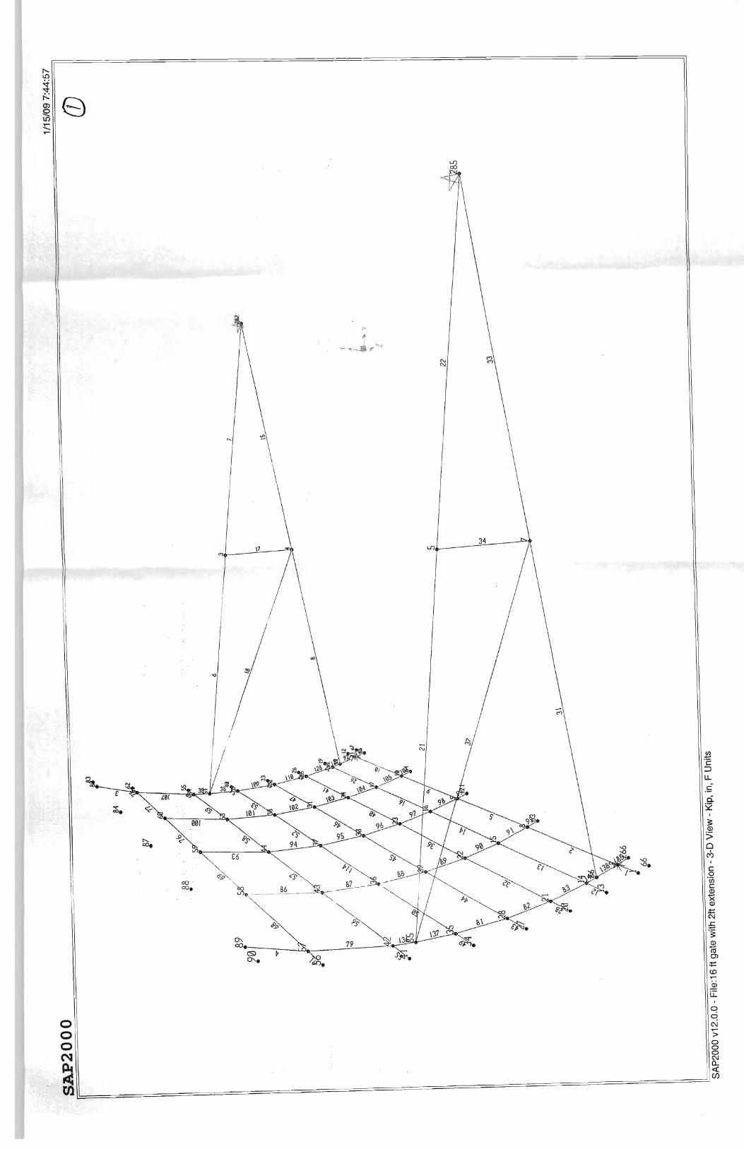
1.3 Trunnion Reaction
X Y
Resultant
Reaction , R
46.79 k 5.49 k 47.11 k (Ref#3)
1.4 Bearing Pressure
= 5000 psi
= 2409 psi < 5000 psi
OK
The following computations are performed to find maximumbearing pressure at the existing tainter gates
trunnions.
Maximum reaction at the trunnion developes under a combination of dead, mud, ice, hydrostatic and
earthquake load under gate closed condition. Reactions shown below are for unfactored loads.
Allowable bearing
pressure
Induced bearing
pressure, R/A
(Section 4-3(b), Ref # 1)
Job No. 08-015H Vol. /Sheet No. of
Contract/Client TetraTech, Robles Diversion Dam (CESPL)
Phase/Subject Tainter Gate Analysis
Design Topic Trunnion Bearing Check
Made By VRG Date 01/14/09 Checked By PD Date 02/01/09 Page No.
Trunnion Bearing Pressure 2/13/2009
10:10 AM10

Job Number 08-015H
Volume/Sheet No. of
Client/Contract Tt/Robles Diversion
Phase/Subject 30 ft Tainter Gate Analysis
Design Topic Loading Conditions and DCRs
Made By VRG Date 1/16/2008 Checked By SVL Date 3/16/2009 Page No.
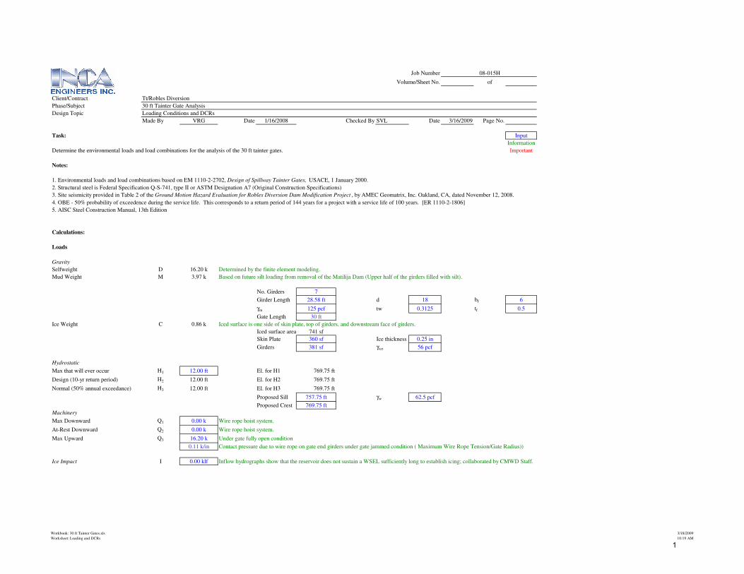
Task: Input
Information
Determine the environmental loads and load combinations for the analysis of the 30 ft tainter gates. Important
Notes:
1. Environmental loads and load combinations based on EM 1110-2-2702, Design of Spillway Tainter Gates, USACE, 1 January 2000.
2. Structural steel is Federal Specification Q-S-741, type II or ASTM Designation A7 (Original Construction Specifications)
3. Site seismicity provided in Table 2 of the Ground Motion Hazard Evaluation for Robles Diversion Dam Modification Project , by AMEC Geomatrix, Inc. Oakland, CA, dated November 12, 2008.
4. OBE - 50% probability of exceedence during the service life. This corresponds to a return period of 144 years for a project with a service life of 100 years. [ER 1110-2-1806]
5. AISC Steel Construction Manual, 13th Edition
Calculations:
Loads
Gravity
Selfweight D 16.20 k Determined by the finite element modeling.
Mud Weight M 3.97 k Based on future silt loading from removal of the Matilija Dam (Upper half of the girders filled with silt).
No. Girders 7
Girder Length 28.58 ft d 18 bf 6
γm 125 pcf tw 0.3125 tf 0.5
Gate Length 30 ft
Ice Weight C 0.86 k Iced surface is one side of skin plate, top of girders, and downstream face of girders.
Iced surface area 741 sf
Skin Plate 360 sf Ice thickness 0.25 in
Girders 381 sf γice 56 pcf
Hydrostatic
Max that will ever occur H1 12.00 ft El. for H1 769.75 ft
Design (10-yr return period) H2 12.00 ft El. for H2 769.75 ft
Normal (50% annual exceedance) H3 12.00 ft El. for H3 769.75 ft
Proposed Sill 757.75 ft γw 62.5 pcf
Proposed Crest 769.75 ft
Machinery
Max Downward Q1 0.00 k Wire rope hoist system.
At-Rest Downward Q2 0.00 k Wire rope hoist system.
Max Upward Q3 16.20 k Under gate fully open condition
0.11 k/in Contact pressure due to wire rope on gate end girders under gate jammed condition ( Maximum Wire Rope Tension/Gate Radius))
Ice Impact I 0.00 klf Inflow hydrographs show that the reservoir does not sustain a WSEL sufficiently long to establish icing; collaborated by CMWD Staff.
Workbook: 30 ft Tainter Gates.xls
Worksheet: Loading and DCRs
3/18/2009
10:19 AM
1
Job Number 08-015H
Volume/Sheet No. of
Client/Contract Tt/Robles Diversion
Phase/Subject 30 ft Tainter Gate Analysis
Design Topic Loading Conditions and DCRs
Made By VRG Date 1/16/2008 Checked By SVL Date 3/16/2009 Page No.
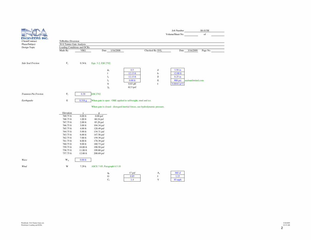
Side Seal Friction Fs 0.34 k Eqn. 3-2, EM 2702.
µs 0.5 d 3.50 in
l 12.13 ft h 12.00 ft
l1 12.13 ft δ 0.25 in
l2 0.00 ft E 900 psi sealsunlimited.com
S 0.83 plf I 0.0044 in^3
γw 62.5 pcf
Trunnion Pin Friction Ft 0.30 EM 2702
Earthquake E 0.318 g When gate is open - OBE applied to selfweight, mud and ice.
When gate is closed - disregard inertial forces, use hydrodynamic pressure.
Elevation y p
769.75 ft 0.00 ft 0.00 psf
768.75 ft 1.00 ft 60.24 psf
767.75 ft 2.00 ft 85.20 psf
766.75 ft 3.00 ft 104.34 psf
765.75 ft 4.00 ft 120.49 psf
764.75 ft 5.00 ft 134.71 psf
763.75 ft 6.00 ft 147.56 psf
762.75 ft 7.00 ft 159.39 psf
761.75 ft 8.00 ft 170.39 psf
760.75 ft 9.00 ft 180.73 psf
759.75 ft 10.00 ft 190.50 psf
758.75 ft 11.00 ft 199.80 psf
757.75 ft 12.00 ft 208.69 psf
Wave WA 0.00 ft
Wind W 7.29 k ASCE 7-05, Paragraph 6.5.10
qh 17 psf As 360 sf
G 0.85 I 1.15
Cf 1.4 V 85 mph
Workbook: 30 ft Tainter Gates.xls
Worksheet: Loading and DCRs
3/18/2009
10:19 AM
2
Job Number 08-015H
Volume/Sheet No. of
Client/Contract Tt/Robles Diversion
Phase/Subject 30 ft Tainter Gate Analysis
Design Topic Loading Conditions and DCRs
Made By VRG Date 1/16/2008 Checked By SVL Date 3/16/2009 Page No.
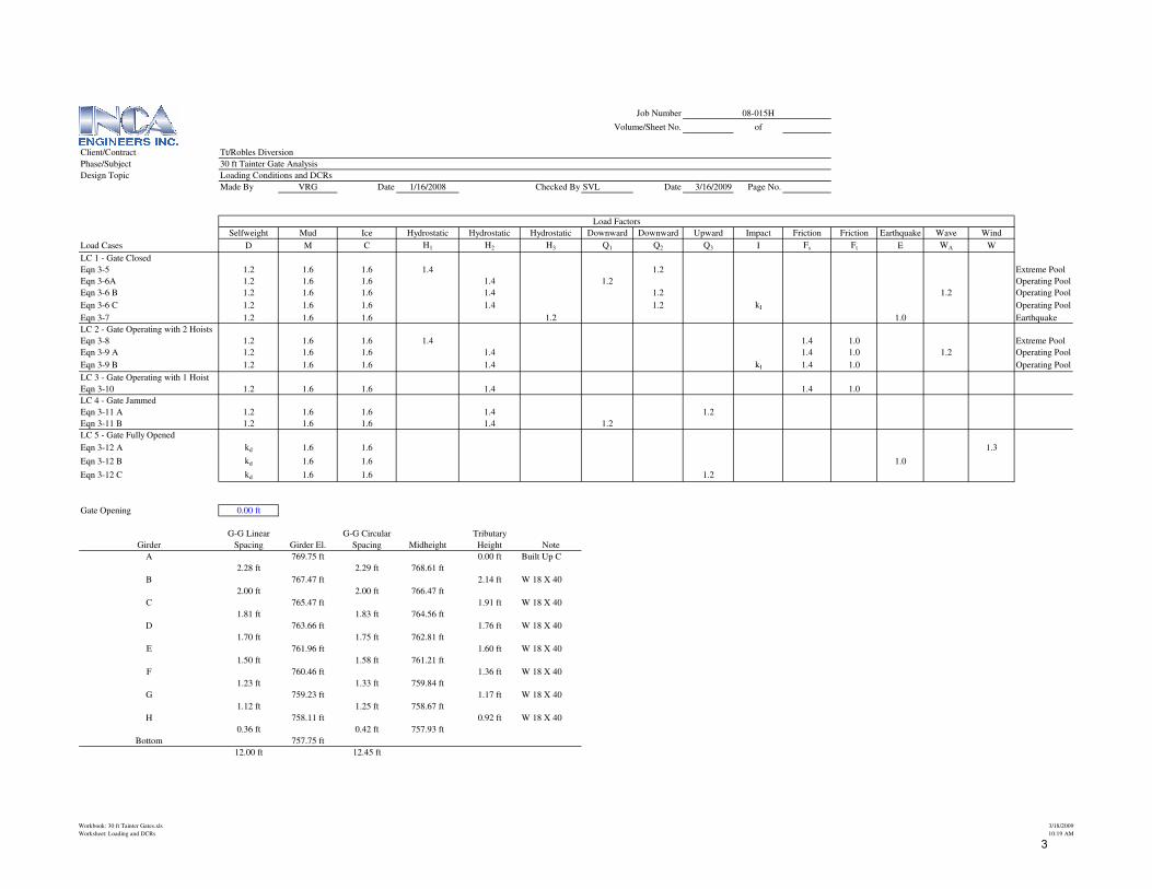
Selfweight Mud Ice Hydrostatic Hydrostatic Hydrostatic Downward Downward Upward Impact Friction Friction Earthquake Wave Wind
Load Cases D M C H1 H2 H3 Q1 Q2 Q3 I Fs Ft E WA W
LC 1 - Gate Closed
Eqn 3-5 1.2 1.6 1.6 1.4 1.2 Extreme Pool
Eqn 3-6A 1.2 1.6 1.6 1.4 1.2 Operating Pool
Eqn 3-6 B 1.2 1.6 1.6 1.4 1.2 1.2 Operating Pool
Eqn 3-6 C 1.2 1.6 1.6 1.4 1.2 kI Operating Pool
Eqn 3-7 1.2 1.6 1.6 1.2 1.0 Earthquake
LC 2 - Gate Operating with 2 Hoists
Eqn 3-8 1.2 1.6 1.6 1.4 1.4 1.0 Extreme Pool
Eqn 3-9 A 1.2 1.6 1.6 1.4 1.4 1.0 1.2 Operating Pool
Eqn 3-9 B 1.2 1.6 1.6 1.4 kI 1.4 1.0 Operating Pool
LC 3 - Gate Operating with 1 Hoist
Eqn 3-10 1.2 1.6 1.6 1.4 1.4 1.0
LC 4 - Gate Jammed
Eqn 3-11 A 1.2 1.6 1.6 1.4 1.2
Eqn 3-11 B 1.2 1.6 1.6 1.4 1.2
LC 5 - Gate Fully Opened
Eqn 3-12 A kd 1.6 1.6 1.3
Eqn 3-12 B kd 1.6 1.6 1.0
Eqn 3-12 C kd 1.6 1.6 1.2
Gate Opening 0.00 ft
G-G Linear G-G Circular Tributary
Girder Spacing Girder El. Spacing Midheight Height Note
A 769.75 ft 0.00 ft Built Up C
2.28 ft 2.29 ft 768.61 ft
B 767.47 ft 2.14 ft W 18 X 40
2.00 ft 2.00 ft 766.47 ft
C 765.47 ft 1.91 ft W 18 X 40
1.81 ft 1.83 ft 764.56 ft
D 763.66 ft 1.76 ft W 18 X 40
1.70 ft 1.75 ft 762.81 ft
E 761.96 ft 1.60 ft W 18 X 40
1.50 ft 1.58 ft 761.21 ft
F 760.46 ft 1.36 ft W 18 X 40
1.23 ft 1.33 ft 759.84 ft
G 759.23 ft 1.17 ft W 18 X 40
1.12 ft 1.25 ft 758.67 ft
H 758.11 ft 0.92 ft W 18 X 40
0.36 ft 0.42 ft 757.93 ft
Bottom 757.75 ft
12.00 ft 12.45 ft
Load Factors
Workbook: 30 ft Tainter Gates.xls
Worksheet: Loading and DCRs
3/18/2009
10:19 AM
3
Job Number 08-015H
Volume/Sheet No. of
Client/Contract Tt/Robles Diversion
Phase/Subject 30 ft Tainter Gate Analysis
Design Topic Loading Conditions and DCRs
Made By VRG Date 1/16/2008 Checked By SVL Date 3/16/2009 Page No.
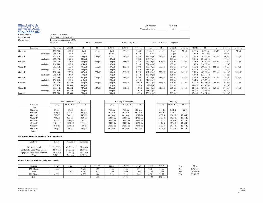
Location Elevation y for H1 Hs1 Hs1 E for H1 E for H1 y for H2 Hs2 Hs2 E for H2 E for H2 y for H3 Hs3 Hs3 E for H3 E for H3
Girder A 769.75 ft 0.00 ft 0 psf 41 plf 0 psf 37 plf 0.00 ft 0.00 psf 41 plf 0 psf 37 plf 0.00 ft 0.00 psf 41 plf 0 psf 37 plf
midheight 768.61 ft 1.14 ft 71 psf 64 psf 1.14 ft 71.28 psf 64 psf 1.14 ft 71.28 psf 64 psf
Girder B 767.47 ft 2.28 ft 143 psf 295 plf 91 psf 185 plf 2.28 ft 142.55 psf 295 plf 91 psf 185 plf 2.28 ft 142.55 psf 295 plf 91 psf 185 plf
midheight 766.47 ft 3.28 ft 205 psf 109 psf 3.28 ft 204.97 psf 109 psf 3.28 ft 204.97 psf 109 psf
Girder C 765.47 ft 4.28 ft 267 psf 504 plf 125 psf 235 plf 4.28 ft 267.40 psf 504 plf 125 psf 235 plf 4.28 ft 267.40 psf 504 plf 125 psf 235 plf
midheight 764.56 ft 5.19 ft 324 psf 137 psf 5.19 ft 324.09 psf 137 psf 5.19 ft 324.09 psf 137 psf
Girder D 763.66 ft 6.09 ft 381 psf 666 plf 149 psf 260 plf 6.09 ft 380.79 psf 666 plf 149 psf 260 plf 6.09 ft 380.79 psf 666 plf 149 psf 260 plf
midheight 762.81 ft 6.94 ft 434 psf 159 psf 6.94 ft 433.94 psf 159 psf 6.94 ft 433.94 psf 159 psf
Girder E 761.96 ft 7.79 ft 487 psf 775 plf 168 psf 268 plf 7.79 ft 487.09 psf 775 plf 168 psf 268 plf 7.79 ft 487.09 psf 775 plf 168 psf 268 plf
midheight 761.21 ft 8.54 ft 534 psf 176 psf 8.54 ft 533.99 psf 176 psf 8.54 ft 533.99 psf 176 psf
Girder F 760.46 ft 9.29 ft 581 psf 787 plf 184 psf 249 plf 9.29 ft 580.89 psf 787 plf 184 psf 249 plf 9.29 ft 580.89 psf 787 plf 184 psf 249 plf
midheight 759.84 ft 9.91 ft 619 psf 190 psf 9.91 ft 619.25 psf 190 psf 9.91 ft 619.25 psf 190 psf
Girder G 759.23 ft 10.52 ft 658 psf 768 plf 195 psf 228 plf 10.52 ft 657.61 psf 768 plf 195 psf 228 plf 10.52 ft 657.61 psf 768 plf 195 psf 228 plf
midheight 758.67 ft 11.08 ft 692 psf 201 psf 11.08 ft 692.45 psf 201 psf 11.08 ft 692.45 psf 201 psf
Girder H 758.11 ft 11.64 ft 727 psf 529 plf 206 psf 151 plf 11.64 ft 727.30 psf 529 plf 206 psf 151 plf 11.64 ft 727.30 psf 529 plf 206 psf 151 plf
midheight 757.93 ft 11.82 ft 739 psf 207 psf 11.82 ft 738.65 psf 207 psf 11.82 ft 738.65 psf 207 psf
Bottom 757.75 ft 12.00 ft 750 psf 209 psf 12.00 ft 750.01 psf 209 psf 12.00 ft 750.01 psf 209 psf
Location (3-5) (3-6 A,B,C) (3-7) (3-5) (3-6 A,B,C) (3-7) (3-5) (3-6 A,B,C) (3-7)
Top
Girder A 57 plf 57 plf 85 plf 70 k-in 70 k-in 105 k-in 0.81 K 0.81 K 1.22 K
Girder B 414 plf 414 plf 540 plf 507 k-in 507 k-in 662 k-in 5.91 K 5.91 K 7.72 K
Girder C 706 plf 706 plf 840 plf 865 k-in 865 k-in 1029 k-in 10.09 K 10.09 K 12.00 K
Girder D 933 plf 933 plf 1059 plf 1143 k-in 1143 k-in 1298 k-in 13.33 K 13.33 K 15.14 K
Girder E 1085 plf 1085 plf 1198 plf 1329 k-in 1329 k-in 1467 k-in 15.50 K 15.50 K 17.12 K
Girder F 1101 plf 1101 plf 1193 plf 1349 k-in 1349 k-in 1462 k-in 15.74 K 15.74 K 17.05 K
Girder G 1075 plf 1075 plf 1150 plf 1318 k-in 1318 k-in 1409 k-in 15.37 K 15.37 K 16.44 K
Girder H 740 plf 740 plf 785 plf 907 k-in 907 k-in 962 k-in 10.58 K 10.58 K 11.22 K
Bottom
Unfactored Trunnion Reactions for Lateral Loads
Load Type Load Trunnion 1 Trunnion 2
Hydrostatic Load 135.00 kip 67.50 kip 67.50 kip
Earthquake Load (Gate Closed) 48.40 kip 24.20 kip 24.20 kip
Equipment Load (Gate Jammed) 24.54 kip 12.27 kip 12.27 kip
Wind 7.29 kip 3.64 kip 3.64 kip
Girder A Section Modulus (Built up Channel)
Element b (in) h (in) t (in) A (in2) X (in) AX (in3) d (in) I0 (in4) Ad2
(in4) Xbar 9.0 in
D/S Flange 4.000 0.250 1.00 17.88 17.88 8.88 0.01 78.77 IXX 269.2 in^4
Web 17.500 0.250 4.38 9.00 39.38 0.00 111.65 0.00 Sxc 29.9 in^3
U/S Flange 4.000 0.250 1.00 0.13 0.13 8.88 0.01 78.77 Sxt 29.9 in^3
SUM 6.38 57.38 111.66 157.53
Shear (Vu)Load Combinations (wu) Bending Moment (Mu)
Workbook: 30 ft Tainter Gates.xls
Worksheet: Loading and DCRs
3/18/2009
10:19 AM
4
Job Number 08-015H
Volume/Sheet No. of
Client/Contract Tt/Robles Diversion
Phase/Subject 30 ft Tainter Gate Analysis
Design Topic Loading Conditions and DCRs
Made By VRG Date 1/16/2008 Checked By SVL Date 3/16/2009 Page No.
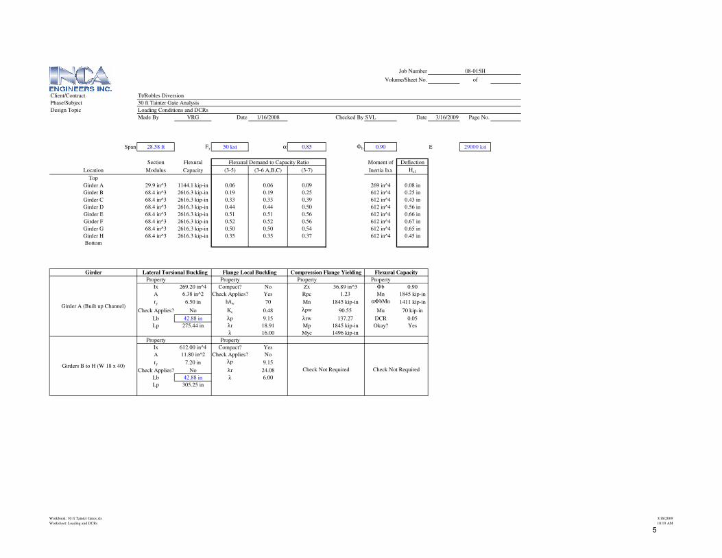
Span 28.58 ft Fy 50 ksi α 0.85 Φb 0.90 E 29000 ksi
Section Flexural Moment of Deflection
Location Modulus Capacity (3-5) (3-6 A,B,C) (3-7) Inertia Ixx Hs1
Top
Girder A 29.9 in^3 1144.1 kip-in 0.06 0.06 0.09 269 in^4 0.08 in
Girder B 68.4 in^3 2616.3 kip-in 0.19 0.19 0.25 612 in^4 0.25 in
Girder C 68.4 in^3 2616.3 kip-in 0.33 0.33 0.39 612 in^4 0.43 in
Girder D 68.4 in^3 2616.3 kip-in 0.44 0.44 0.50 612 in^4 0.56 in
Girder E 68.4 in^3 2616.3 kip-in 0.51 0.51 0.56 612 in^4 0.66 in
Girder F 68.4 in^3 2616.3 kip-in 0.52 0.52 0.56 612 in^4 0.67 in
Girder G 68.4 in^3 2616.3 kip-in 0.50 0.50 0.54 612 in^4 0.65 in
Girder H 68.4 in^3 2616.3 kip-in 0.35 0.35 0.37 612 in^4 0.45 in
Bottom
Girder
Property Property Property Property
Ix 269.20 in^4 Compact? No Zx 36.89 in^3 Φb 0.90
A 6.38 in^2 Check Applies? Yes Rpc 1.23 Mn 1845 kip-in
ry 6.50 in h/tw 70 Mn 1845 kip-in αΦbMn 1411 kip-in
Check Applies? No Kc 0.48 λpw 90.55 Mu 70 kip-in
Lb 42.88 in λp 9.15 λrw 137.27 DCR 0.05
Lp 275.44 in λr 18.91 Mp 1845 kip-in Okay? Yes
λ 16.00 Myc 1496 kip-in
Property Property
Ix 612.00 in^4 Compact? Yes
A 11.80 in^2 Check Applies? No
ry 7.20 in λp 9.15
Check Applies? No λr 24.08
Lb 42.88 in λ 6.00
Lp 305.25 in
Flange Local Buckling Compression Flange Yielding
Flexural Demand to Capacity Ratio
Girder A (Built up Channel)
Girders B to H (W 18 x 40)Check Not Required
Flexural Capacity
Check Not Required
Lateral Torsional Buckling
Workbook: 30 ft Tainter Gates.xls
Worksheet: Loading and DCRs
3/18/2009
10:19 AM
5
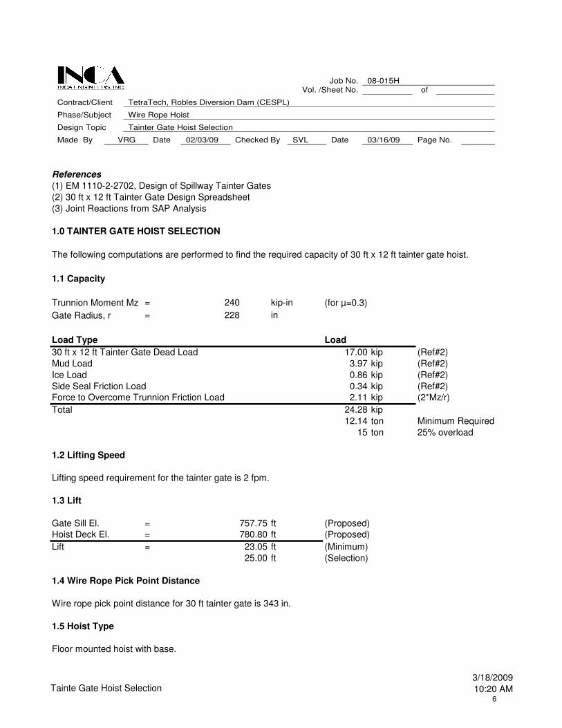
References
(1) EM 1110-2-2702, Design of Spillway Tainter Gates
(2) 30 ft x 12 ft Tainter Gate Design Spreadsheet
(3) Joint Reactions from SAP Analysis
1.0 TAINTER GATE HOIST SELECTION
1.1 Capacity
Trunnion Moment Mz = 240 kip-in (for µ=0.3)
Gate Radius, r = 228 in
Load Type Load
30 ft x 12 ft Tainter Gate Dead Load 17.00 kip (Ref#2)
Mud Load 3.97 kip (Ref#2)
Ice Load 0.86 kip (Ref#2)
Side Seal Friction Load 0.34 kip (Ref#2)
Force to Overcome Trunnion Friction Load 2.11 kip (2*Mz/r)
Total 24.28 kip
12.14 ton Minimum Required
15 ton 25% overload
1.2 Lifting Speed
Lifting speed requirement for the tainter gate is 2 fpm.
1.3 Lift
Gate Sill El. = 757.75 ft (Proposed)
Hoist Deck El. = 780.80 ft (Proposed)
Lift = 23.05 ft (Minimum)
25.00 ft (Selection)
1.4 Wire Rope Pick Point Distance
Wire rope pick point distance for 30 ft tainter gate is 343 in.
1.5 Hoist Type
Floor mounted hoist with base.
The following computations are performed to find the required capacity of 30 ft x 12 ft tainter gate hoist.
Job No. 08-015H Vol. /Sheet No. of
Contract/Client TetraTech, Robles Diversion Dam (CESPL)
Phase/Subject Wire Rope Hoist
Design Topic Tainter Gate Hoist Selection
Made By VRG Date 02/03/09 Checked By SVL Date 03/16/09 Page No.
Tainte Gate Hoist Selection3/18/2009
10:20 AM6
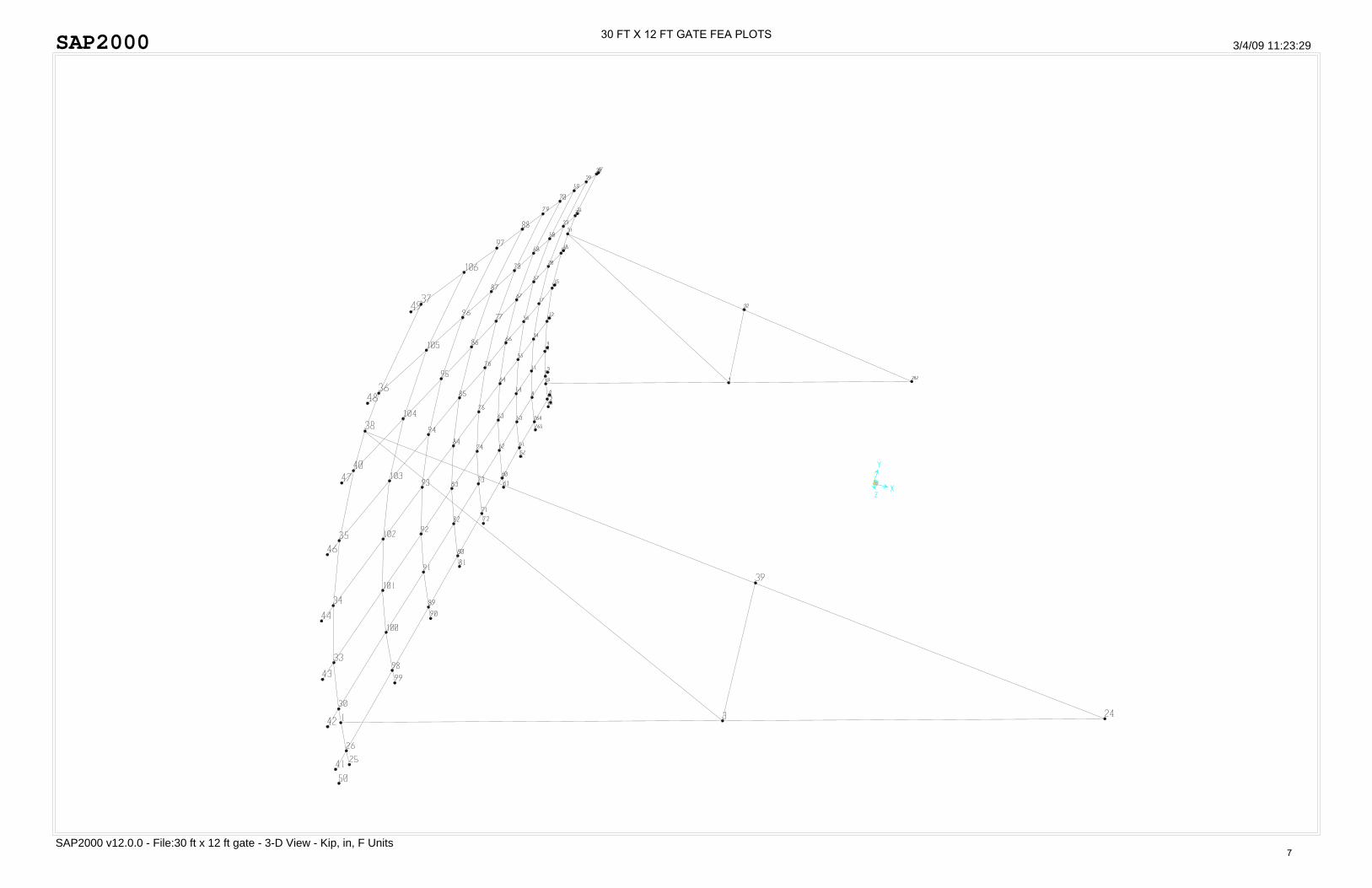
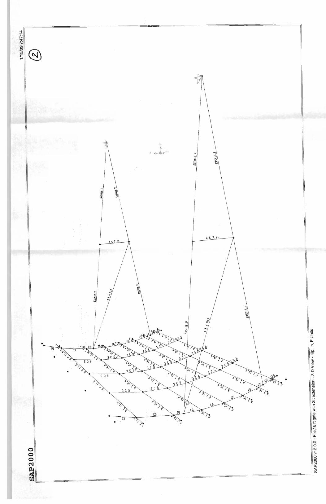
SAP2000
SAP2000 v12.0.0 - File:30 ft x 12 ft gate - 3-D View - Kip, in, F Units
3/4/09 11:23:29 30 FT X 12 FT GATE FEA PLOTS
7
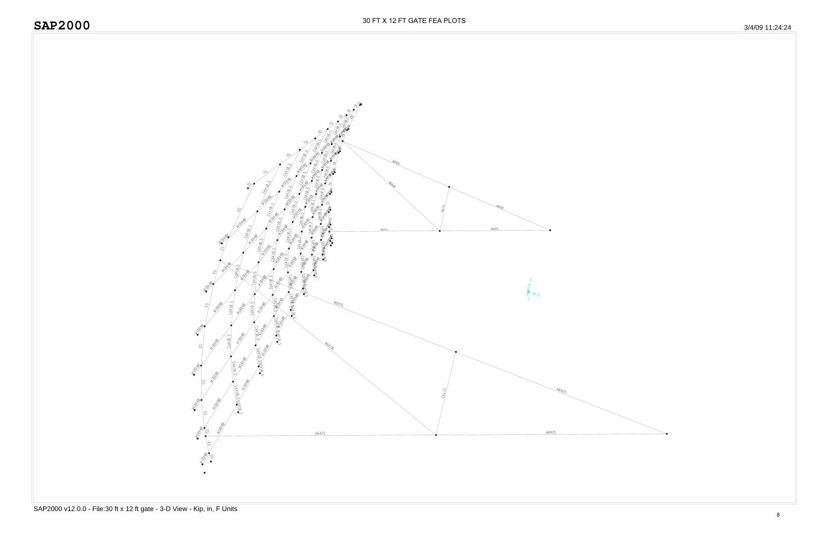
SAP2000
SAP2000 v12.0.0 - File:30 ft x 12 ft gate - 3-D View - Kip, in, F Units
3/4/09 11:24:24 30 FT X 12 FT GATE FEA PLOTS
8
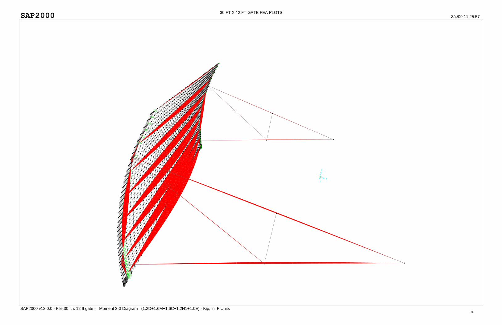
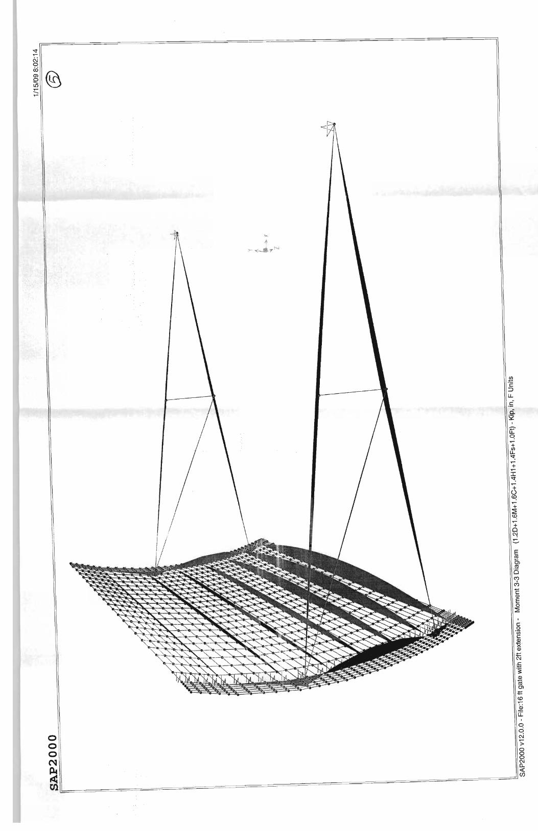
SAP2000
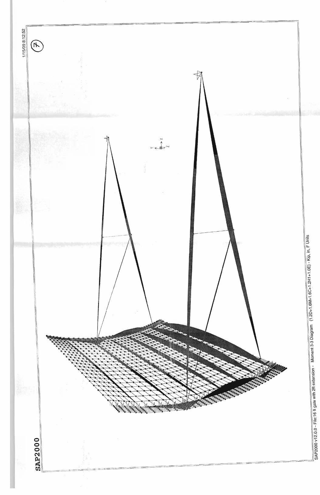
SAP2000 v12.0.0 - File:30 ft x 12 ft gate - Moment 3-3 Diagram (1.2D+1.6M+1.6C+1.2H1+1.0E) - Kip, in, F Units
3/4/09 11:25:57 30 FT X 12 FT GATE FEA PLOTS
9
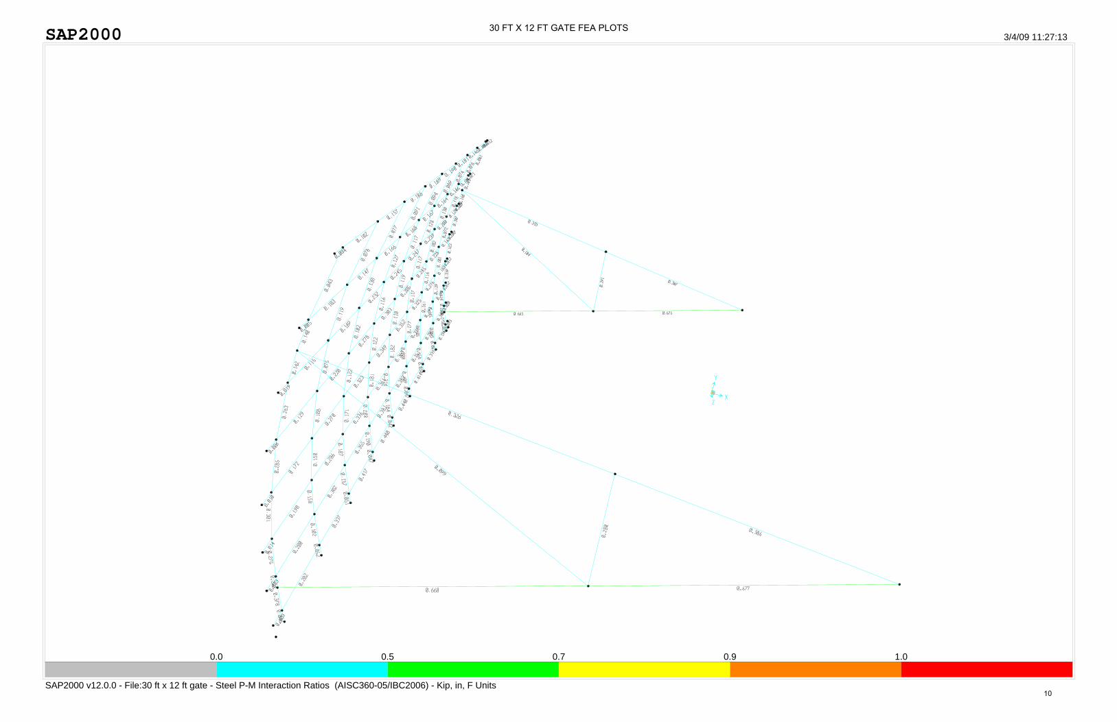
SAP2000
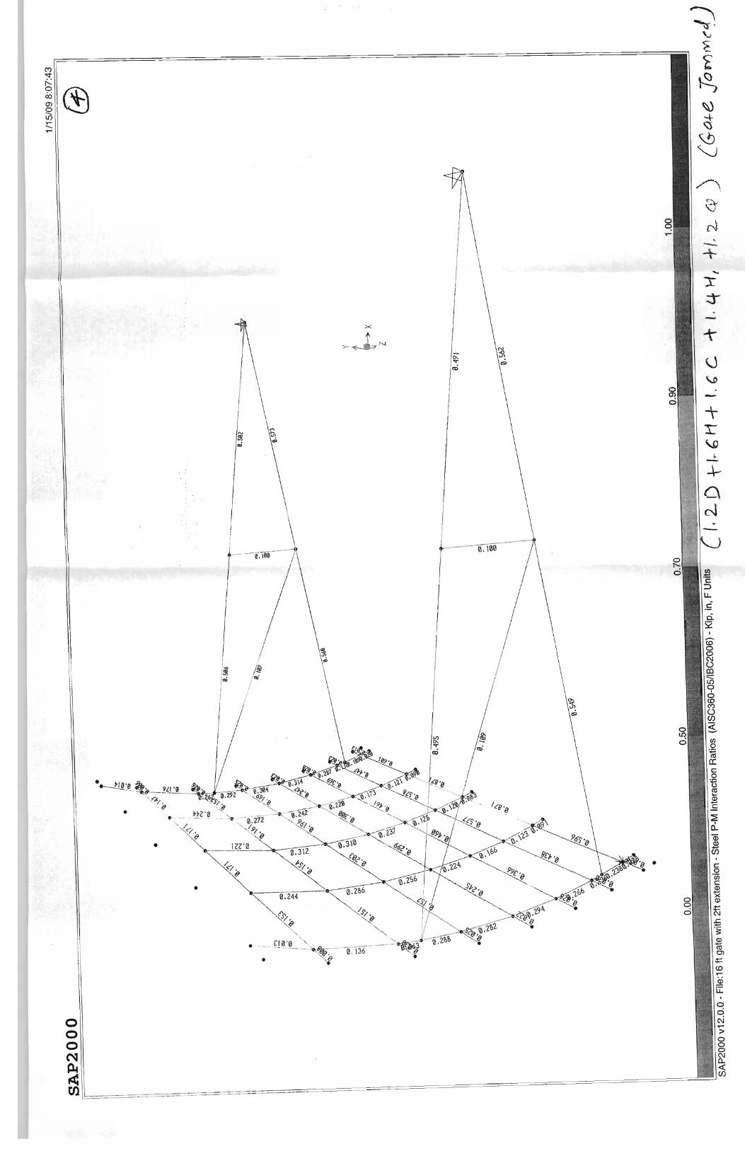
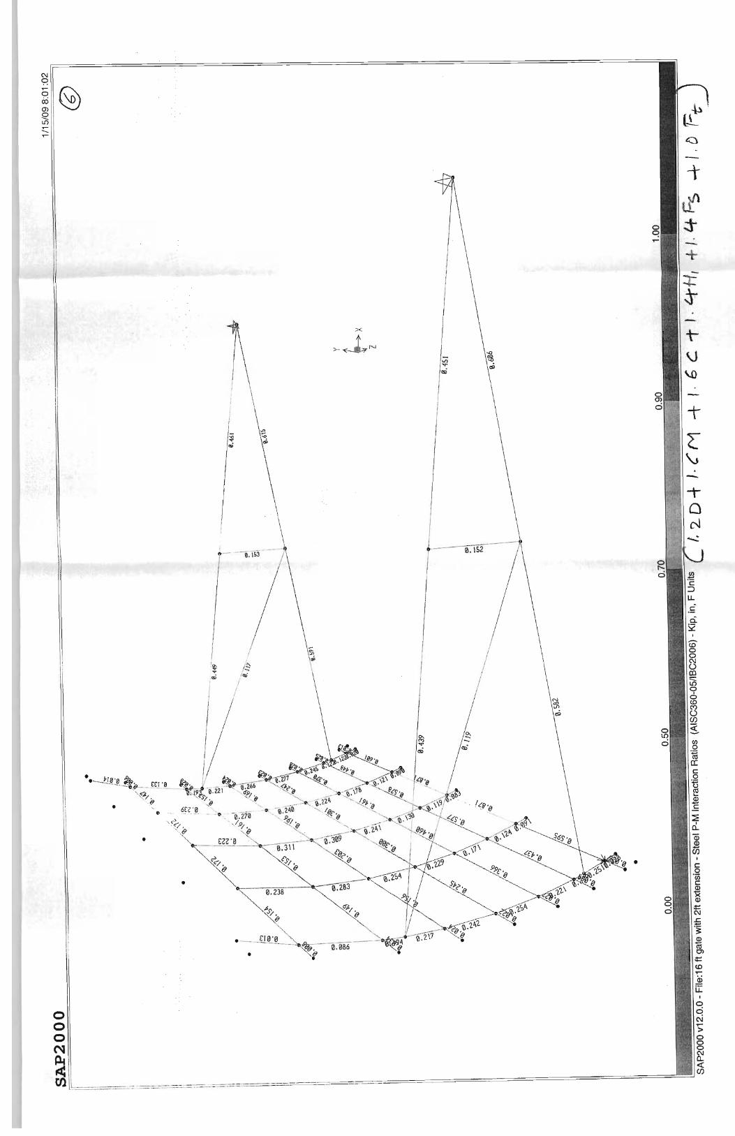
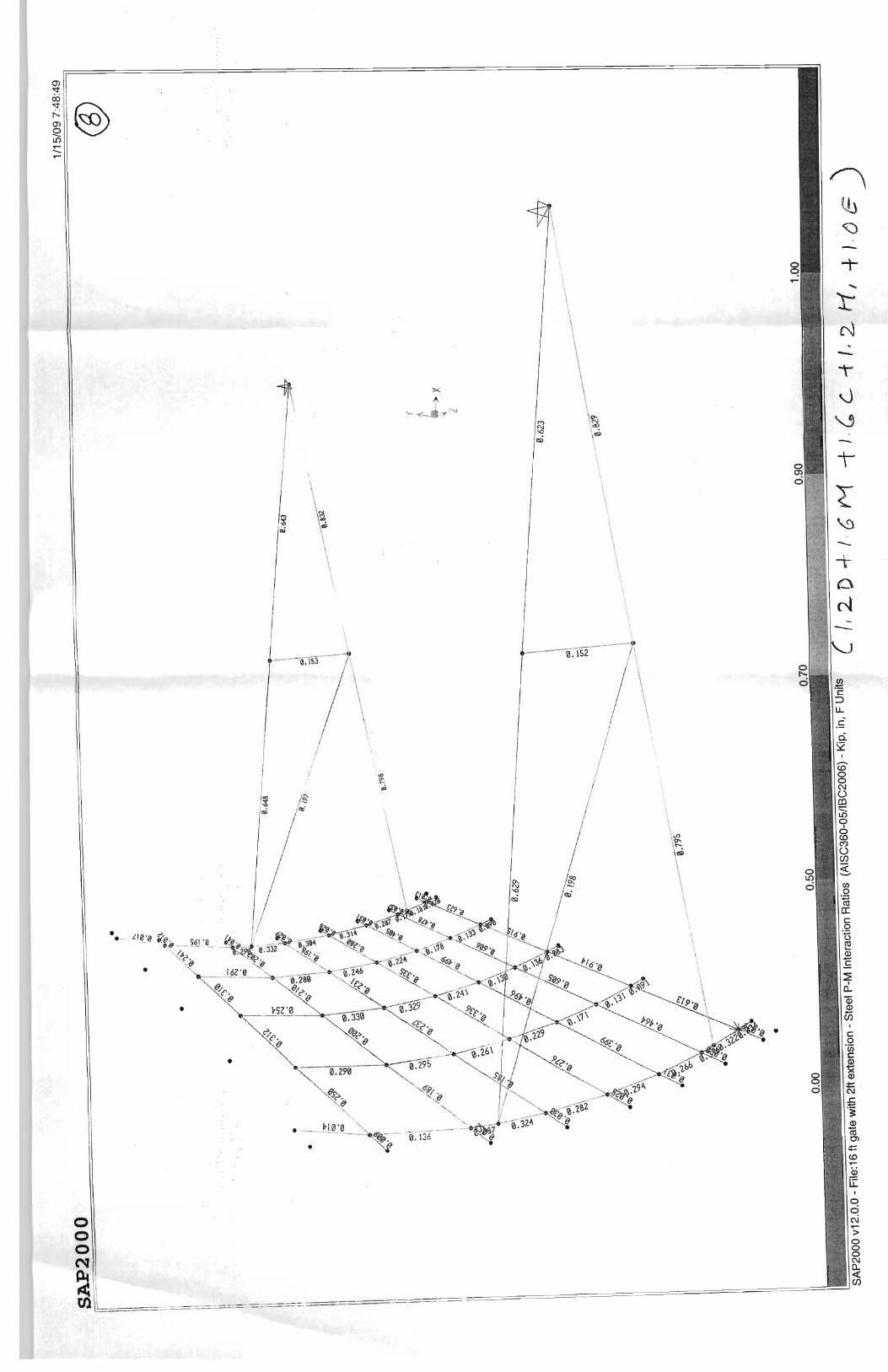
SAP2000 v12.0.0 - File:30 ft x 12 ft gate - Steel P-M Interaction Ratios (AISC360-05/IBC2006) - Kip, in, F Units
3/4/09 11:27:13
0.0 0.5 0.7 0.9 1.0
30 FT X 12 FT GATE FEA PLOTS
10
SAP2000
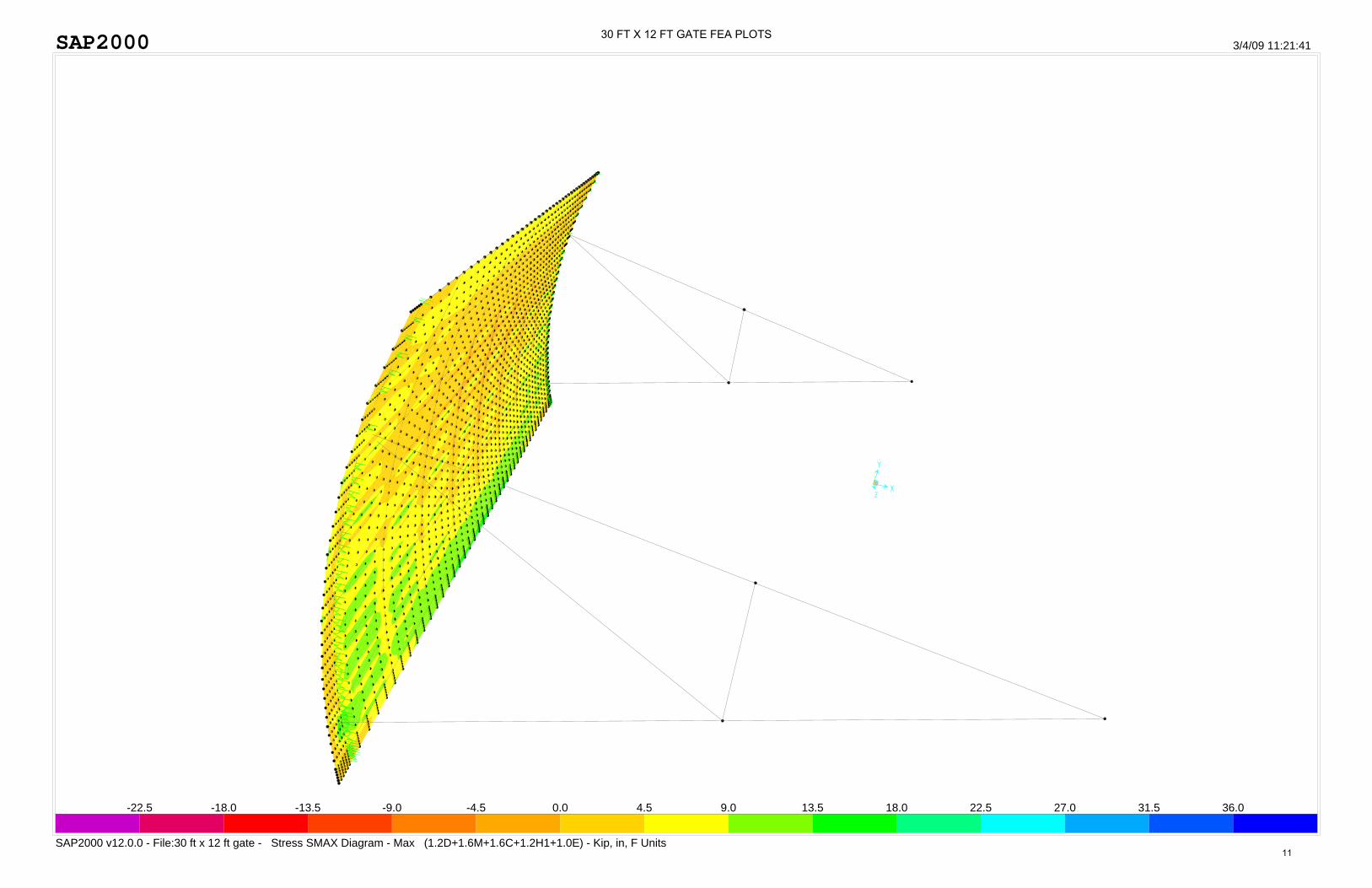
SAP2000 v12.0.0 - File:30 ft x 12 ft gate - Stress SMAX Diagram - Max (1.2D+1.6M+1.6C+1.2H1+1.0E) - Kip, in, F Units
3/4/09 11:21:41
-22.5 -18.0 -13.5 -9.0 -4.5 0.0 4.5 9.0 13.5 18.0 22.5 27.0 31.5 36.0
30 FT X 12 FT GATE FEA PLOTS
11