Embed Size (px)
Citation preview
Technical memorandum
CALIBRATION OF MULTIPORTREFLECTOMETERS
Indexing terms: Measurement and measuring,Microwave measurements
Abstract: The paper describes a calibration tech-nique for multiport reflectometers using only fourdifferent short-circuit terminations and a matchedload. The calibration constants that are evaluatedare the constants associated with the bilinearrelationship which holds between the waves at therelevant measurement ports.
Introduction
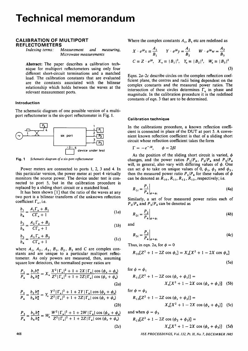
The schematic diagram of one possible version of a multi-port reflectometer is the six-port reflectometer in Fig. 1.
©• rx six port
~ t - 5device under test
Fig. 1 Schematic diagram of a six-port reflectometer
Power meters are connected to ports 1, 2, 3 and 4. Inthis particular version, the power meter at port 4 virtuallymonitors the source power. The device under test is con-nected to port 5, but in the calibration procedure isreplaced by a sliding short circuit or a matched load.
It has been shown [1] that the ratio of the waves at anytwo port is a bilinear transform of the unknown reflectioncoefficient Fu, i.e.
AXTU
CTU + 1
A2 Tu + B
cr,, + \
CTU
(la)
(ib)
(lc)
where Ay, A2, A3, Bu B2, B3 and C are complex con-stants and are unique to a particular multiport reflec-tometer. As only powers are measured, then, assumingsquare low detectors, the normalised power ratios are
a „" z2|r 2z\ru\ cos(02
(2a)
P, b,
P4 bM
P, b,
v— J»
(2b)
P 4 bAb% cos
(2c)
Where the complex constants Au Bx etc are redefined as
X • e»x = ^Bx
(3)
Eqns. 2a-2c describe circles on the complex reflection coef-ficient plane, the centres and radii being dependent on thecomplex constants and the measured power ratios. Theintersection of these circles determines Fu in phase andmagnitude. In the calibration procedure it is the redefinedconstants of eqn. 3 that are to be determined.
Calibration technique
In the calibrations procedure, a known reflection coeffi-cient is connected in place of the DUT at port 5. A conve-nient known reflection coefficient is that of a sliding shortcircuit whose reflection coefficient takes the form
r = -e-jf, 4> = 20/
As the position of the sliding short circuit is varied, 0changes, and the power ratios PJP4, PJPA a n d ^3/^4will, in general, also vary with differing values of </>. Onecan set $ to take on unique values of 0, <f>u <f>2 and (f)3,then the measured power ratio PJP^ for these values of <f)can be denoted a s ^ 1 0 , R 1 1 , R 1 2 , R13,respectively; i.e.
(4a)
Similarly, a set of four measured power ratios each ofP2/P4 and P3/P4 can be denoted as
^2i —
and
Thus, in eqn. 2a, for </> = 0
Rl0[Z2 + 1-2Z cos # J = Xn[X2 + 1 - 2X cos
(4c)
(5a)
468
f o r <j) = 4>x
R^IZ2 + 1-2Z cos (</>2 + 0 J ] =
Xn[X2 + 1 - 2X cos (<px + 0 J ] (5b)
for 0 = 02
Ri2[Z2 + 1 - 2Z cos (02 + 02)] =
Xn[X2 + 1 - 2X cos (0X + 02)] (5c)
and when 0 = 0 3
K1 3[Z2 + 1-2Z cos (02 + 03)] =
XnlX2 + 1 - 2X cos (4>x + 03)] (5d)
IEE PROCEEDINGS, Vol. 132, Pt. H, No. 7, DECEMBER 1985
Subtracting eqns. 5a from 56, 5a from 5c and 5a from 5d for P, Q, Clt C2, and C3 in the resulting expression one
obtains (See Appendix)
"n (M (Z2 + 1) + 2Z(giY cos 0Z + a12 sin 0Z) = 0
where
where
4Xn • sin ( 0x + y ) sin ^ = C12 (66)
(6c)
cos
(10a)
cos 02 - Rl3a3 cos 03]/At (106)a i sin 0! - ^ 1 2 a 2 sin 02 + K13a3 sin 03]/Aj
(10c)
- 2 Z [ K n cos (0Z cos 0 J (7a)
- 2Z[K12 cos (0Z + (j>2) - R10 cos 0 J (7b)
C13 = (^i3-^io)(Z2 + l)
-2Z[K 1 3 cos (0 z + 0 3 ) - J R l o c o s 0 z ] (7c)
dividing eqn. 5a by eqn. 5b and eqn. 5a by eqn. 5c
• 02
c s i n T
12
c13
• 03sin Y
0
Rearranging eqn. 8a
tan <bx = —0i
P • sin y - sin y
0i 09cos - ^ - P • cos - ^
2 2
where
• 02
c, sinT
Re-arranging eqn. 86
Q • sin -£ - sin - 1
tan O,. =
where
c
cos —• - 0 • cos ^2 * 2
• 0 3s inT
(8a)
(8a)
(86)
(9a)
(96)
(9c)
Eliminating tan 0X from eqns. 9a and 9c and substituting
IEE PROCEEDINGS, Vol. 132, Pt. H, No. 7, DECEMBER 1985
and
sin
a, =
02 - 03
sin
• 01siny
01 - 03
(lOd)
(lla)
(116)
sin
a-, =• 03
siny
(lie)
In a similar manner for port 2, the four power ratios ofP2/P4. can be written by examination of eqns. lOa-lOd*
(Z2 + 1) + 2Z(a21 cos 0Z + a22 sin 0Z) = 0
where
(12a)
021 = [(«i - a2 + a3)^2o - ^2ia i cos 0 j
+ /?2 2 a2 cos 0 2 - i?23 a3 cos 03]/A2 (126)
022 = C^2iai sin 0 j - R22<*2 sin 0 2 + i?2 3a3 sin 03]/A2
(12c)
A2 = (R21 — ̂ 2o) a l ~~ (-^22 — ^2o)a2 + (^23 ~ -^2o)a3
(I2d)
Solving for 02 from eqns. 10a and 12a
0Z = tan 1
022 - 012(13)
In the above equation, al l5 a12 etc. are known in terms ofthe power ratios R{j; al5 a2 and <x3 are also known in termsof 0X, 02 and 0 3 , which are set by the sliding short circuit.Thus, 0Z, which is one of the redefined constants of eqn. 3,is determined.
Once 0Z is known, Z can be evaluated from either eqn.10a or eqn. 12a. Once Z and 0Z have been determined, therest of the constants can be found. It is to be noted that Zis in quadratic form, giving rise to two values of Z. Now Zoccurs in the denominator of eqns. 2a-2c: for a perfectlymatched six-port with matched detectors, Z would be zero.On this basis, for a reasonably well matched six-port anddetectors, the smaller value of Z in eqn. 10a is chosen.
It is also to be noted that X is in quadratic form, givingrise to two values of X and hence two values of Xn. These
469

two values of Xn correspond to the locus of F in the trans-formed plane corresponding to | F | -> 0 and | F | —> oo[2]. The correct value of Xn (in most cases) can thus bededuced. Another way to eliminate this ambiguity is touse, in addition, a matched termination as a calibratingstandard; then from eqn. 2a
(14a)
(14b)
(14c)
x
and,
y
p" p
in
similarly,
Pi
i rh
- 0
• 0
and
in-o
Calibration procedure
Step 1: Matched termination connected to port 5; then, byinserting the measured power ratios in eqns. 14a-14c, Xn,Yn and Wn are determined.Step 2: Sliding short circuit connected to port 5. Evaluatethe measured power ratios R-ti as defined in eqns. 4a-4c,for four different values of <f) (<j> = 0, </>l5 $ 2 , $3). (pz is nowdetermined from eqn. 13. The value of Z is then deter-mined from eqn. 10a or 12a.Step 3: Determine C l l 5 C12 and C1 3 from eqns. la-lc. (\)x
can then be determined from eqns. 9a or 9c. The value ofX then follows from eqn. 6a.
This completes the evaluation of all the constants ineqn. 2a associated with port 1. The constants associatedwith port 2, i.e. Y and (f)y, are determined from expressionswhich can be written down by examination of eqns. 6a-6c,eqns. la-lc and eqns. 9a — 9b, with the appropriate powerratios. Similarly, for the constants W and (f)w associatedwith port 3.
Conclusions
A computer program based on the scheme outlined in thispaper has been used to calibrate a six- and a seven-portreflectometer. The reflection coefficient of several devicesusing such a calibrated reflectometer agrees within experi-mental uncertainty, compared with values obtained fromconventional measurement.
Acknowledgment
The author wishes to thank Professor A.L. Cullen formany useful discussions and helpful interest.
References
1 ENGEN, G.F.: 'The six port reflectometer: An alternative networkanalyser', IEEE Trans., 1977, MTT-25, pp. 1075-1080
2 KASA, I.: 'Closed form mathematical solutions to some networkanalyser calibration equations', ibid., 1974, IM-23, pp. 399-402
3 CULLEN, A.L, JUDAH, S.K., and NIKRAVESH, F.: 'Impedancemeasurement using a 6-port directional coupler', IEE Proc. H, Micro-waves, Opt. & Antennas, 1980, 127, pp. 92-98
4 WOODS, D.: 'Analysis and calibration theory of the general 6-portreflectometer employing four amplitude detectors', Proc. IEE, 1979,126, (2) pp. 221-228
18th March 1985
Department of Electronic EngineeringUniversity of Hull,Hull HU6 7RX
Appendix
S.K. JUDAH
4180H
The starting point is eqn. 9a and 9c; eliminating tan (j)x
from these two equations
- I sin
_ sin
T sin
(19)
Substituting for P and Q in eqn. 19 from eqns. 9b and 9done obtains
Cuflti - C12 a2 + C13 a3 = 0 (20)
where al5 a2 and a3 are defined in eqns. l l a - l l c . Substitu-ting in eqn. 20 for C l l 5 C12 and C13 from eqns. la-lc, oneobtains
(Z2 + 1)
+ 2Z[{(a1 - a2 + cc3)R10 - RnOti^ cos 0X
+ Ri2a2 C0S 02 ~ ^13 a3 C 0 S $3} C 0 S ^z
+ {^uai sin (fri — -Ri2a2 sin 0 2
+ K1 3a3 s in03} sin 02] = 0 (21)
Substituting in eqn. 21 from eqns. \0b-\0d, leads to
(Z2 + 1) + 2Z(gtl cos <f>z + g12 sin (f>z) = 0
470 IEE PROCEEDINGS, Vol. 132, Pt. H, No. 7, DECEMBER 1985