Embed Size (px)
Citation preview
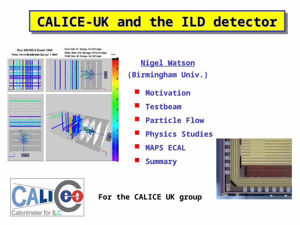
CALICE-UK and the ILD detectorCALICE-UK and the ILD detectorCALICE-UK and the ILD detectorCALICE-UK and the ILD detector
Nigel Watson
(Birmingham Univ.)
For the CALICE UK group
Motivation
Testbeam
Particle Flow
Physics Studies
MAPS ECAL
Summary
ILD-UK, Cambridge, 21-Sep-2007Nigel Watson / Birmingham
Mass (jet1+jet2)
Mass (
jet3
+je
t4)
Mass (
jet3
+je
t4)
Mass (jet1+jet2)
E/E = 60%/EE/E = 60%/E E/E = 30%/EE/E = 30%/E
Equivalent best LEP detector Goal at ILC
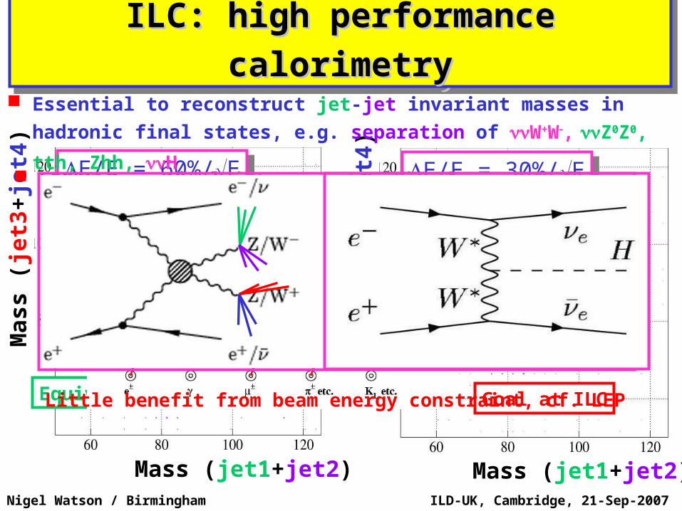
Essential to reconstruct jet-jet invariant masses in hadronic
final states, e.g. separation of W+W, Z0Z0, tth, Zhh, H
ILC: high performance ILC: high performance
calorimetrycalorimetry
ILC: high performance ILC: high performance
calorimetrycalorimetry
LEP/SLD: optimal jet reconstruction by energy flow Explicit association of tracks/clusters Replace poor calorimeter measurements with tracker
measurements – no “double counting”
Little benefit from beam energy constraint, cf. LEP
ILD-UK, Cambridge, 21-Sep-2007Nigel Watson / Birmingham
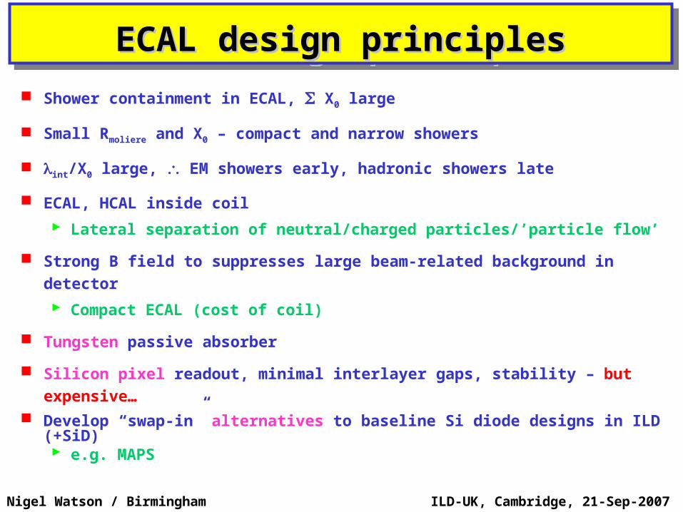
Shower containment in ECAL, X0 large
Small Rmoliere and X0 – compact and narrow showers
int/X0 large, EM showers early, hadronic showers late
ECAL, HCAL inside coil
Lateral separation of neutral/charged particles/’particle flow’
Strong B field to suppresses large beam-related background in detector
Compact ECAL (cost of coil)
Tungsten passive absorber
Silicon pixel readout, minimal interlayer gaps, stability – but expensive…
Develop “swap-in” alternatives to baseline Si diode designs in ILD (+SiD) e.g. MAPS
ECAL design principlesECAL design principlesECAL design principlesECAL design principles
ILD-UK, Cambridge, 21-Sep-2007Nigel Watson / Birmingham
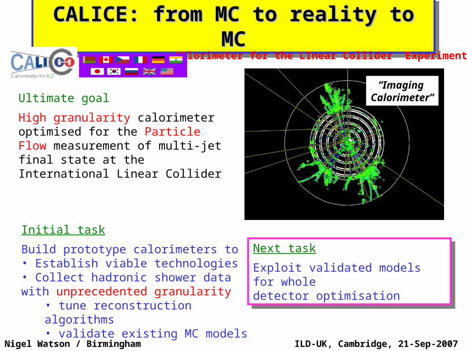
CALICE: from MC to reality to MCCALICE: from MC to reality to MCCALICE: from MC to reality to MCCALICE: from MC to reality to MC
Initial task
Build prototype calorimeters to• Establish viable technologies• Collect hadronic shower data with unprecedented granularity
• tune reconstruction algorithms• validate existing MC models
Ultimate goal
High granularity calorimeter optimised for the Particle Flow measurement of multi-jet final state at the International Linear Collider
CAlorimeter for the LInear Collider Experiment
Scint. Strips-Fe TCMT
“Imaging Calorimeter”
Next task
Exploit validated models for wholedetector optimisation
Next task
Exploit validated models for wholedetector optimisation
ILD-UK, Cambridge, 21-Sep-2007Nigel Watson / Birmingham
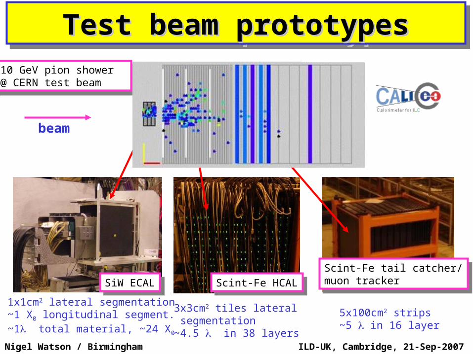
Test beam prototypesTest beam prototypesTest beam prototypesTest beam prototypes
1x1cm2 lateral segmentation~1 X0 longitudinal segment.~1 total material, ~24 X0
3x3cm2 tiles lateral segmentation~4.5 in 38 layers
5x100cm2 strips~5 in 16 layer
10 GeV pion shower @ CERN test beam
10 GeV pion shower @ CERN test beam
SiW ECALSiW ECAL Scint-Fe HCALScint-Fe HCALScint-Fe tail catcher/muon tracker
Scint-Fe tail catcher/muon tracker
beam
ILD-UK, Cambridge, 21-Sep-2007Nigel Watson / Birmingham
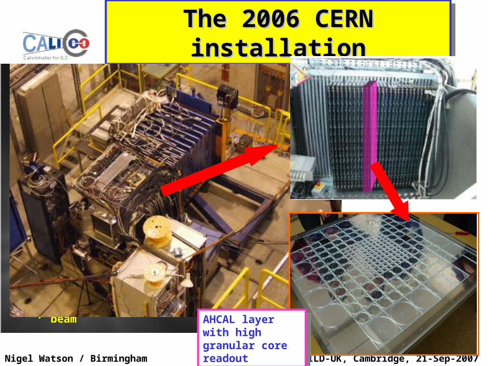
The 2006 CERN The 2006 CERN installationinstallation
The 2006 CERN The 2006 CERN installationinstallation
HCAL
Tail Catcher
ECAL
beam AHCAL layer with high granular core readout
AHCAL layer with high granular core readout
G4 Workshop / 13-Sep-2007Nigel Watson / Birmingham
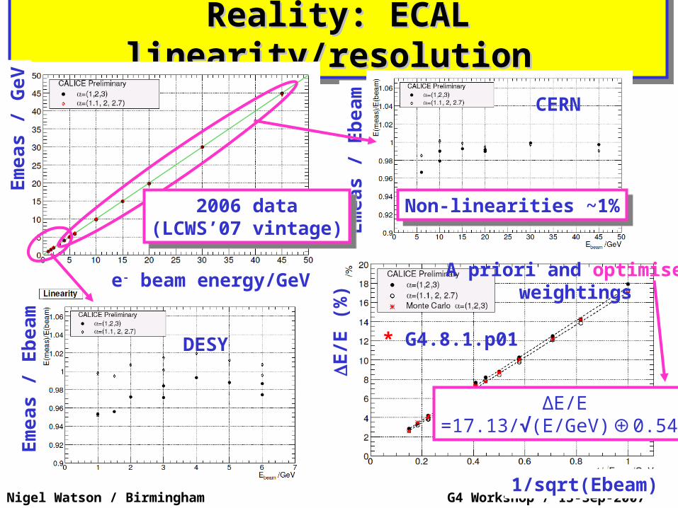
Reality: ECAL linearity/resolution Reality: ECAL linearity/resolution Reality: ECAL linearity/resolution Reality: ECAL linearity/resolution Em
eas /
GeV
e- beam energy/GeV
Em
eas /
Eb
eam
Em
eas /
Eb
eam
DESY
CERN
Non-linearities ~1%Non-linearities ~1%
* G4.8.1.p01E
/E (
%)
1/sqrt(Ebeam)
∆E/E=17.13/√(E/GeV)⊕0.54%
A priori and optimised weightings
2006 data(LCWS’07 vintage)
2006 data(LCWS’07 vintage)
G4 Workshop / 13-Sep-2007Nigel Watson / Birmingham
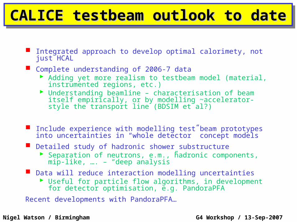
CALICE testbeam outlook to dateCALICE testbeam outlook to dateCALICE testbeam outlook to dateCALICE testbeam outlook to date
Integrated approach to develop optimal calorimety, not just HCAL
Complete understanding of 2006-7 data Adding yet more realism to testbeam model (material,
instrumented regions, etc.) Understanding beamline – characterisation of beam itself
empirically, or by modelling ~accelerator-style the transport line (BDSIM et al?)
Include experience with modelling test beam prototypes into uncertainties in “whole detector” concept models
Detailed study of hadronic shower substructure Separation of neutrons, e.m., hadronic components, mip-
like, …. – “deep analysis” Data will reduce interaction modelling uncertainties
Useful for particle flow algorithms, in development for detector optimisation, e.g. PandoraPFA
Recent developments with PandoraPFA…
ILD-UK, Cambridge, 21-Sep-2007CALICE-UK, Cambridge, 20/9/2007
Nigel Watson / BirminghamMark Thomson
Recent Improvements
Technical Improvements minor bug fixes reduced memory footprint (~ factor 2) by on-the-fly deleting of temporary clusters, rather than waiting to event end
Use of tracks (still TrackCheater) Photon Identification
EM cluster profile identification Particle ID
Much improved particle ID : electrons, conversions,
KS+-, -p (no impact on PFA) Some tagging of K± ± and ± ±kinksNo explicit muon ID yet
Fragment Removal “Calibration” – some interesting issues…
Overview:
ILD-UK, Cambridge, 21-Sep-2007CALICE-UK, Cambridge, 20/9/2007
Nigel Watson / BirminghamMark Thomson
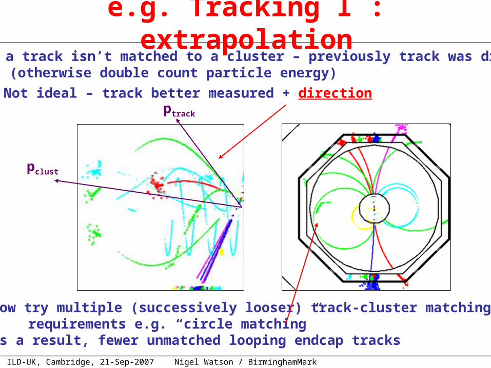
e.g. Tracking I : extrapolation If a track isn’t matched to a cluster – previously track was dropped (otherwise double count particle energy) Not ideal – track better measured + direction
ptrack
pclust
Now try multiple (successively looser) track-cluster matching requirements e.g. “circle matching” As a result, fewer unmatched looping endcap tracks
ILD-UK, Cambridge, 21-Sep-2007CALICE-UK, Cambridge, 20/9/2007
Nigel Watson / BirminghamMark Thomson
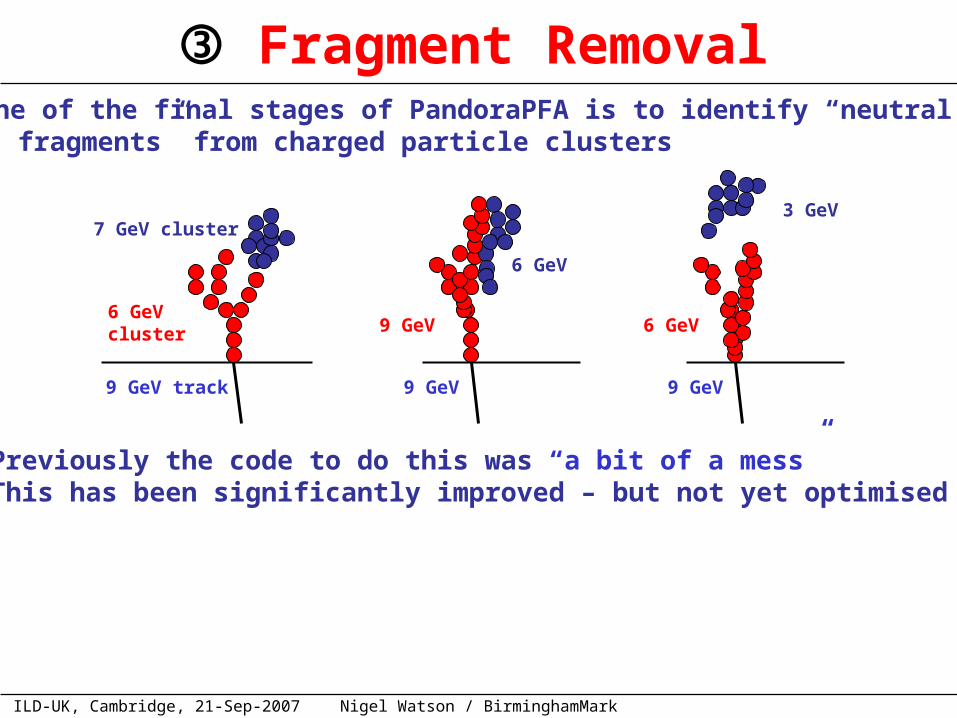
Fragment Removal One of the final stages of PandoraPFA is to identify “neutral fragments” from charged particle clusters
9 GeV track
6 GeV cluster
7 GeV cluster
9 GeV
9 GeV
6 GeV
9 GeV
6 GeV
3 GeV
Previously the code to do this was “a bit of a mess” This has been significantly improved – but not yet optimised
ILD-UK, Cambridge, 21-Sep-2007CALICE-UK, Cambridge, 20/9/2007
Nigel Watson / BirminghamMark Thomson
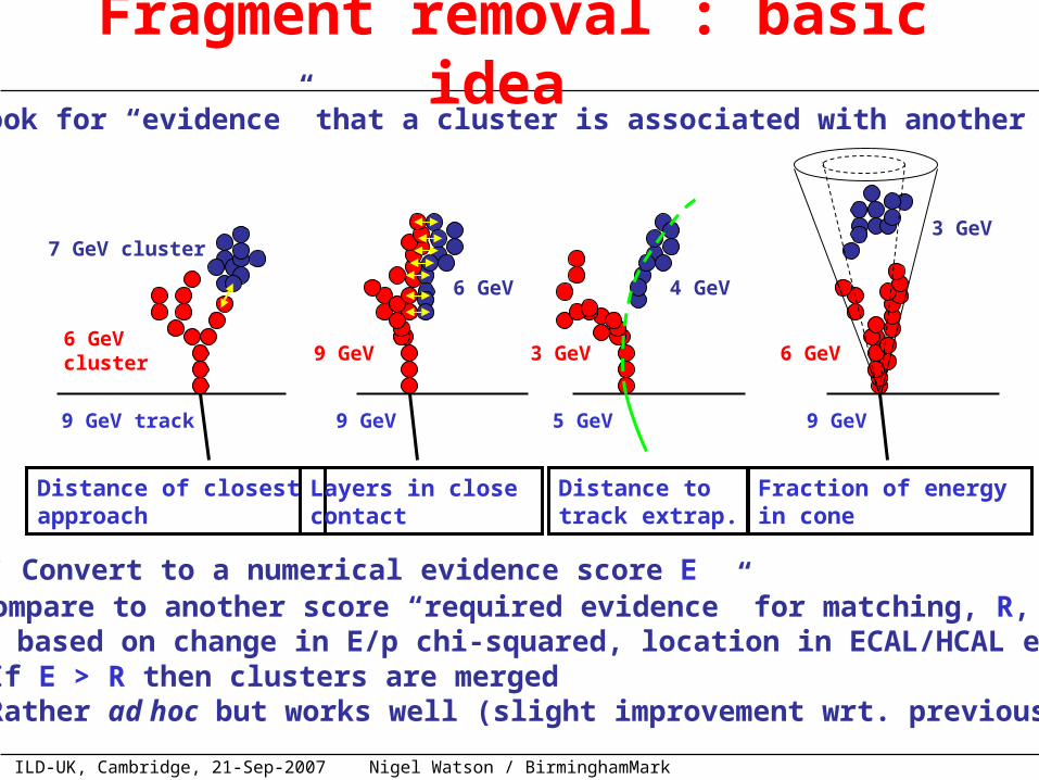
Fragment removal : basic idea Look for “evidence” that a cluster is associated with another
9 GeV track
6 GeV cluster
7 GeV cluster
9 GeV
6 GeV
3 GeV
9 GeV
9 GeV
6 GeV
5 GeV
3 GeV
4 GeV
Distance of closest approach
Layers in close contact
Distance totrack extrap.
Fraction of energy in cone
Convert to a numerical evidence score E Compare to another score “required evidence” for matching, R, based on change in E/p chi-squared, location in ECAL/HCAL etc. If E > R then clusters are merged Rather ad hoc but works well (slight improvement wrt. previous)
ILD-UK, Cambridge, 21-Sep-2007CALICE-UK, Cambridge, 20/9/2007
Nigel Watson / BirminghamMark Thomson
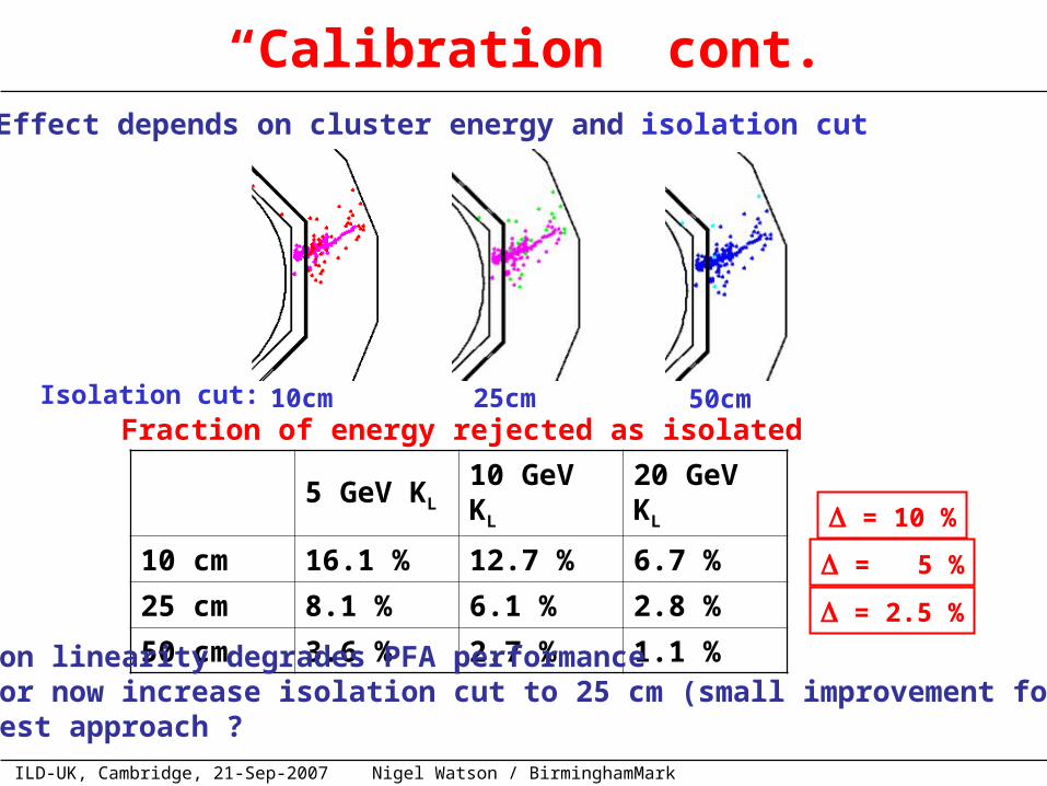
“Calibration” cont. Effect depends on cluster energy and isolation cut
10cm 25cm 50cmIsolation cut:
5 GeV KL 10 GeV KL 20 GeV KL
10 cm 16.1 % 12.7 % 6.7 %
25 cm 8.1 % 6.1 % 2.8 %
50 cm 3.6 % 2.7 % 1.1 %
Fraction of energy rejected as isolated
= 10 %
= 5 %
= 2.5 %
Non linearity degrades PFA performance For now increase isolation cut to 25 cm (small improvement for PFA) Best approach ?
ILD-UK, Cambridge, 21-Sep-2007CALICE-UK, Cambridge, 20/9/2007
Nigel Watson / BirminghamMark Thomson
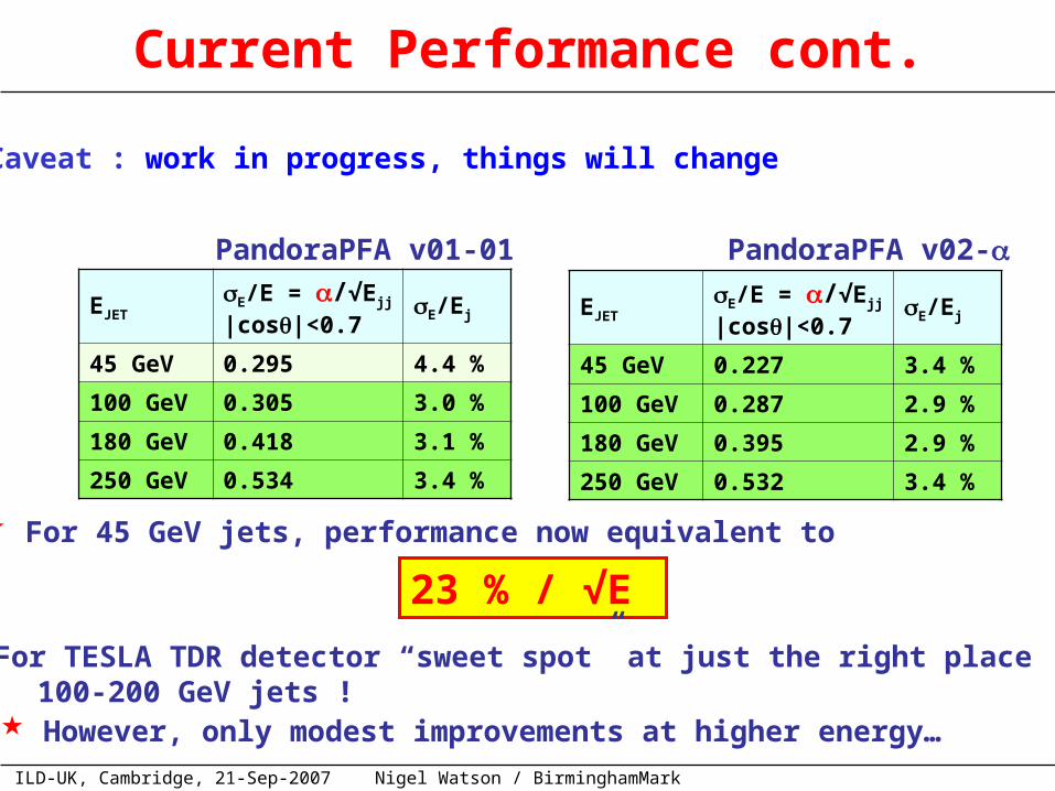
EJETE/E = /√Ejj |cos|<0.7
E/Ej
45 GeV 0.295 4.4 %
100 GeV 0.305 3.0 %
180 GeV 0.418 3.1 %
250 GeV 0.534 3.4 %
EJETE/E = /√Ejj |cos|<0.7
E/Ej
45 GeV 0.227 3.4 %
100 GeV 0.287 2.9 %
180 GeV 0.395 2.9 %
250 GeV 0.532 3.4 %
PandoraPFA v01-01 PandoraPFA v02-
Current Performance cont.
For 45 GeV jets, performance now equivalent to
23 % / √E
For TESLA TDR detector “sweet spot” at just the right place 100-200 GeV jets !
Caveat : work in progress, things will change
However, only modest improvements at higher energy…
ILD-UK, Cambridge, 21-Sep-2007CALICE-UK, Cambridge, 20/9/2007
Nigel Watson / BirminghamMark Thomson
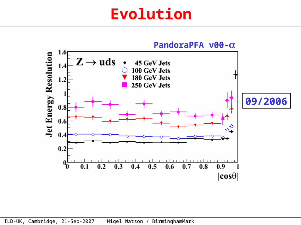
Evolution
PandoraPFA v00-
09/2006
ILD-UK, Cambridge, 21-Sep-2007CALICE-UK, Cambridge, 20/9/2007
Nigel Watson / BirminghamMark Thomson
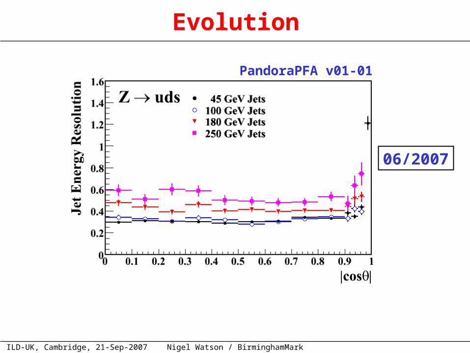
Evolution
PandoraPFA v01-01
06/2007
ILD-UK, Cambridge, 21-Sep-2007CALICE-UK, Cambridge, 20/9/2007
Nigel Watson / BirminghamMark Thomson
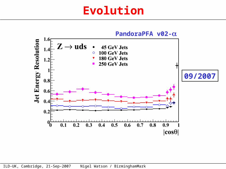
Evolution
09/2007
PandoraPFA v02-
ILD-UK, Cambridge, 21-Sep-2007CALICE-UK, Cambridge, 20/9/2007
Nigel Watson / BirminghamMark Thomson
Summary
Concentrated on lower energy performance – major improvements !Also improvements in structure of code + almost certainly some new
Some small improvements for higher energy jets
Summary:
Development of high performance PFA is highly non-trivial User feedback very helpful (thanks Wenbiao) Major improvements on current performance possible
• “just” needs effort + fresh ideas PandoraPFA needs a spring-clean (a lot of now redundant code) + plenty of scope for speed improvements
• again needs new effort (I just don’t have time)
Perspective:
ILD-UK, Cambridge, 21-Sep-2007CALICE-UK, Cambridge, 20/9/2007
Nigel Watson / BirminghamMark Thomson
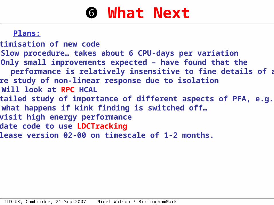
What Next
Optimisation of new code Slow procedure… takes about 6 CPU-days per variation Only small improvements expected – have found that the performance is relatively insensitive to fine details of alg.
More study of non-linear response due to isolation• Will look at RPC HCAL
Detailed study of importance of different aspects of PFA, e.g. what happens if kink finding is switched off… Revisit high energy performance Update code to use LDCTracking Release version 02-00 on timescale of 1-2 months.
Plans:
ILD-UK, Cambridge, 21-Sep-2007Nigel Watson / Birmingham
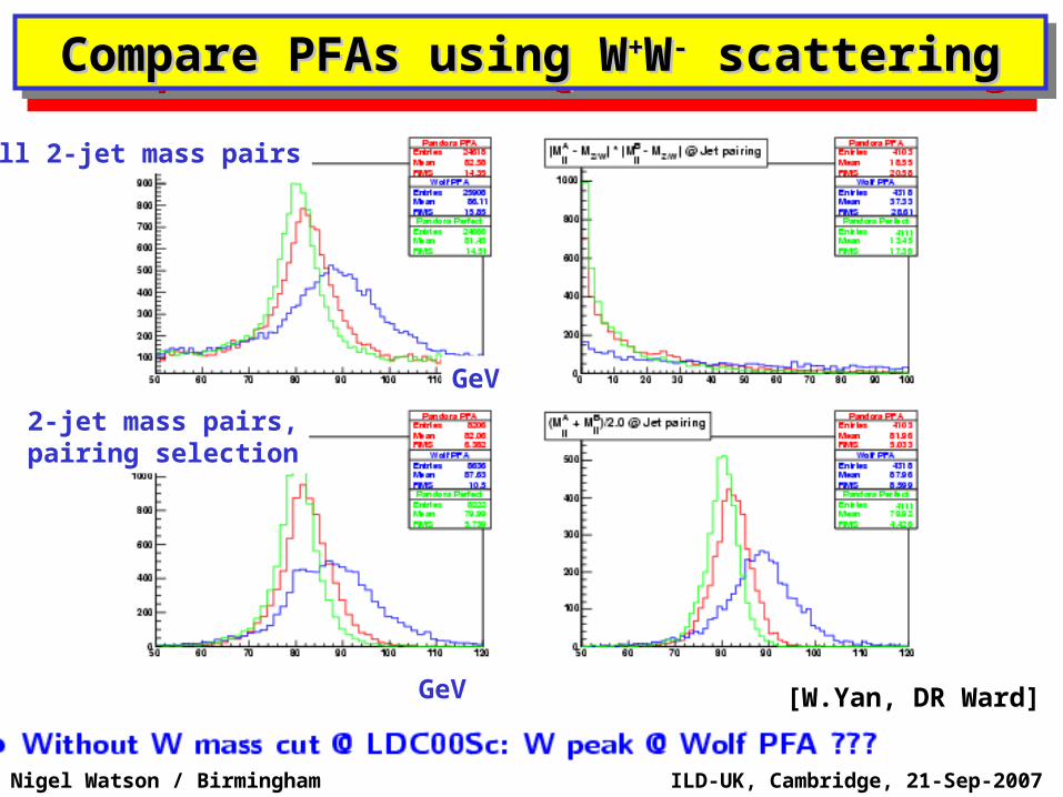
Compare PFAs using WCompare PFAs using W++WW-- scattering scatteringCompare PFAs using WCompare PFAs using W++WW-- scattering scattering
All 2-jet mass pairs
2-jet mass pairs,pairing selection
GeV
GeV [W.Yan, DR Ward]
ILD-UK, Cambridge, 21-Sep-2007Nigel Watson / Birmingham
ILD-UK, Cambridge, 21-Sep-2007Nigel Watson / Birmingham
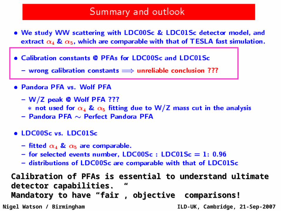
Calibration of PFAs is essential to understand ultimate Calibration of PFAs is essential to understand ultimate detector capabilities.detector capabilities.Mandatory to have “fair”, objective comparisons!Mandatory to have “fair”, objective comparisons!
ILD-UK, Cambridge, 21-Sep-2007Nigel Watson / Birmingham
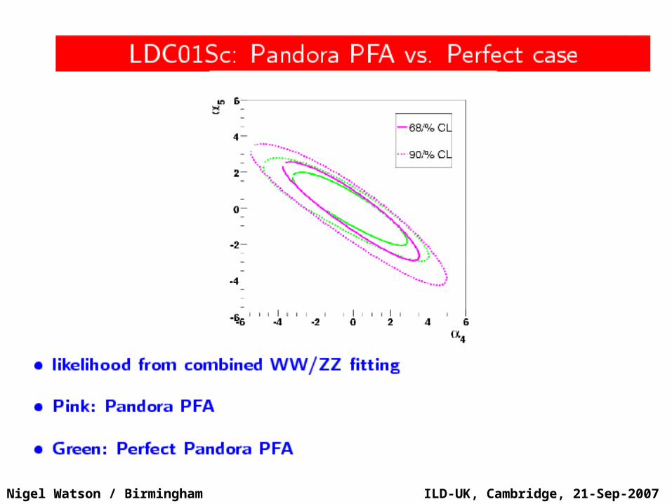
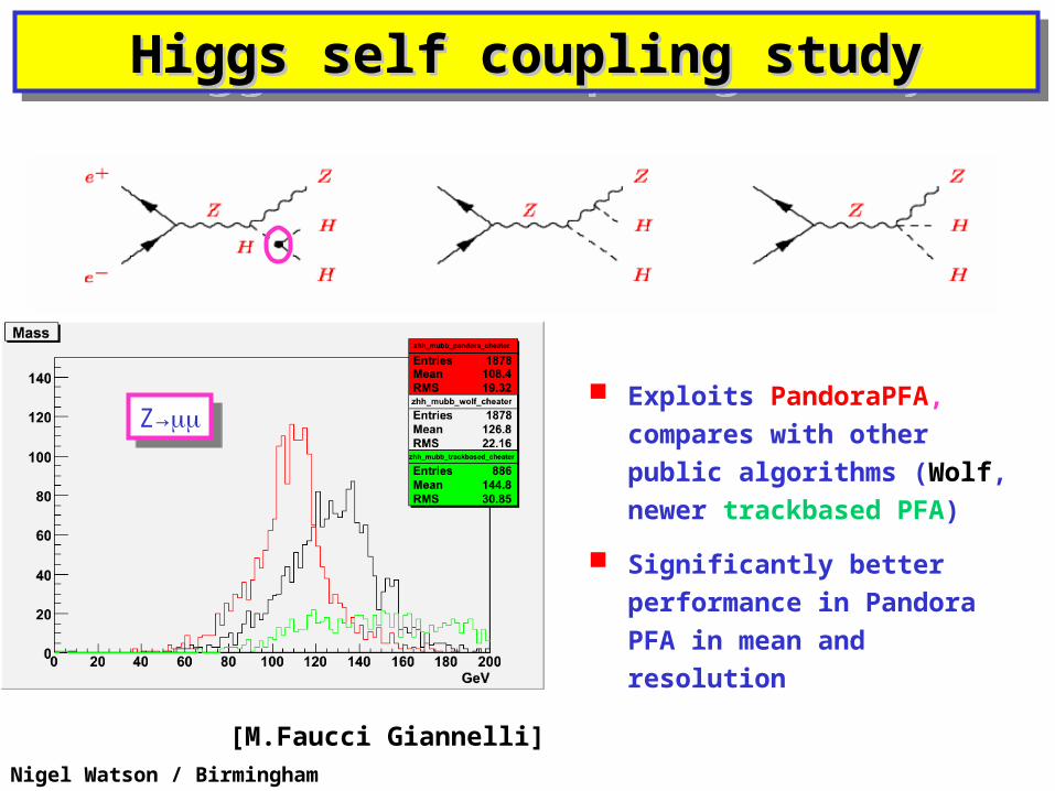
Higgs self coupling studyHiggs self coupling studyHiggs self coupling studyHiggs self coupling study
Michele slides I
[M.Faucci Giannelli]
Exploits PandoraPFA, compares with other public algorithms (Wolf, newer trackbased PFA)
Significantly better performance in Pandora PFA in mean and resolution
Z→Z→
ILD-UK, Cambridge, 21-Sep-2007Nigel Watson / Birmingham
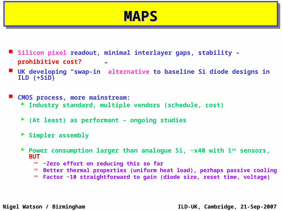
Silicon pixel readout, minimal interlayer gaps, stability – prohibitive cost?
UK developing “swap-in” alternative to baseline Si diode designs in ILD (+SiD)
CMOS process, more mainstream: Industry standard, multiple vendors (schedule, cost)
(At least) as performant – ongoing studies
Simpler assembly
Power consumption larger than analogue Si, ~x40 with 1st sensors, BUT
~Zero effort on reducing this so far Better thermal properties (uniform heat load), perhaps passive cooling Factor ~10 straightforward to gain (diode size, reset time, voltage)
MAPSMAPSMAPSMAPS
ILD-UK, Cambridge, 21-Sep-2007Nigel Watson / Birmingham
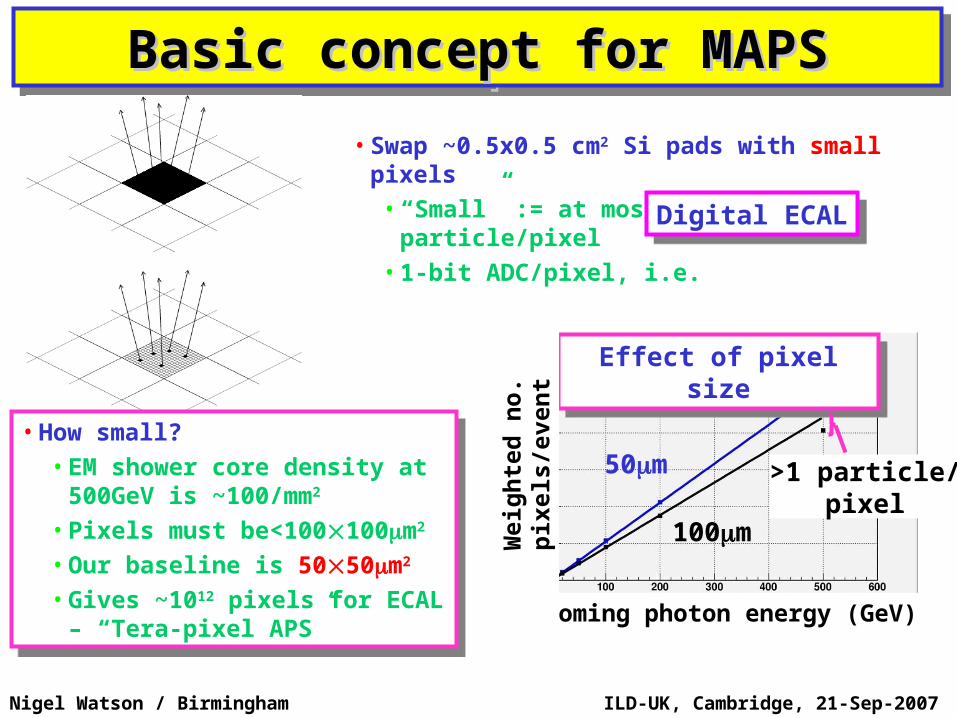
Basic concept for MAPSBasic concept for MAPSBasic concept for MAPSBasic concept for MAPS
• How small?• EM shower core density at
500GeV is ~100/mm2
• Pixels must be<100100m2
• Our baseline is 5050m2
• Gives ~1012 pixels for ECAL – “Tera-pixel APS”
• How small?• EM shower core density at
500GeV is ~100/mm2
• Pixels must be<100100m2
• Our baseline is 5050m2
• Gives ~1012 pixels for ECAL – “Tera-pixel APS”
• Swap ~0.5x0.5 cm2 Si pads with small pixels• “Small” := at most one particle/pixel• 1-bit ADC/pixel, i.e.
Digital ECALDigital ECAL
Effect of pixel sizeEffect of pixel size
50m
100m
>1 particle/pixel
Incoming photon energy (GeV)
Weig
hte
d n
o.
pix
els
/even
t
ILD-UK, Cambridge, 21-Sep-2007Nigel Watson / Birmingham
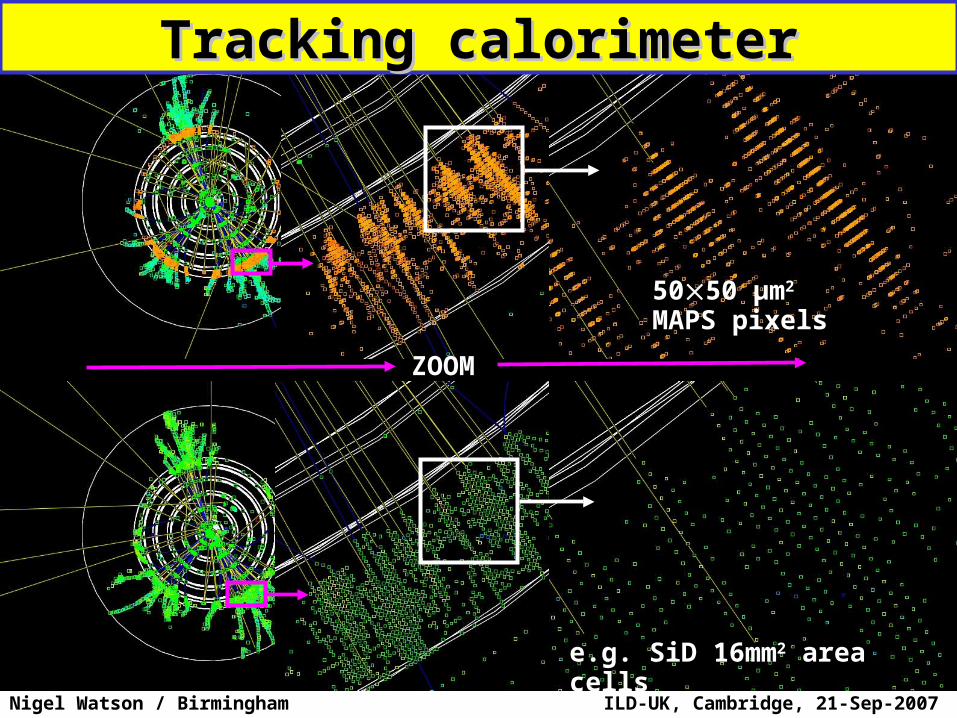
e.g. SiD 16mm2 area cells
ZOOM
5050 μm2
MAPS pixels
Tracking calorimeterTracking calorimeter
ILD-UK, Cambridge, 21-Sep-2007Nigel Watson / Birmingham
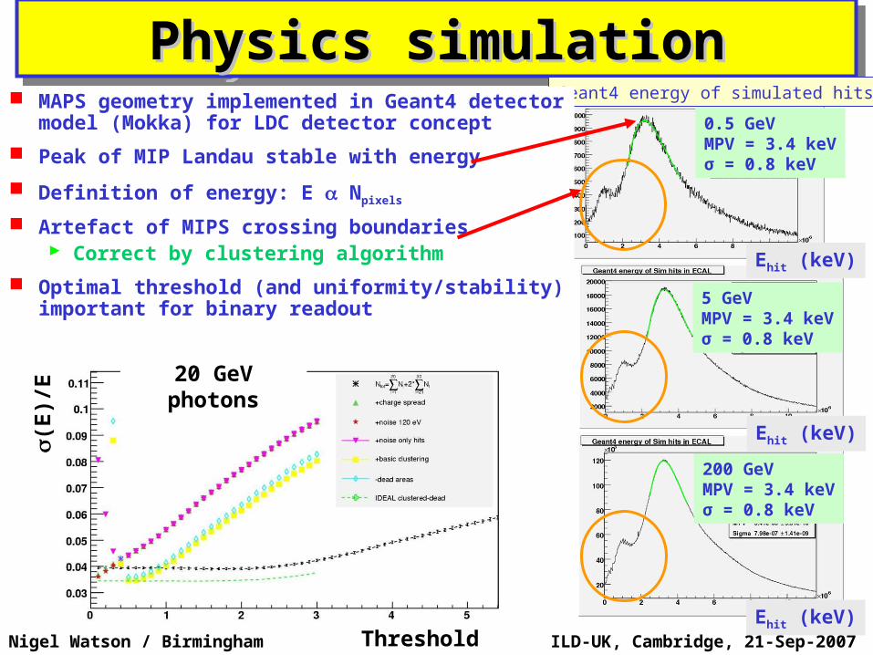
Physics simulationPhysics simulationPhysics simulationPhysics simulation0.5 GeVMPV = 3.4 keVσ = 0.8 keV
5 GeVMPV = 3.4 keVσ = 0.8 keV
200 GeVMPV = 3.4 keVσ = 0.8 keV
Geant4 energy of simulated hits
Ehit (keV)
Ehit (keV)
Ehit (keV)
MAPS geometry implemented in Geant4 detector model (Mokka) for LDC detector concept
Peak of MIP Landau stable with energy
Definition of energy: E Npixels
Artefact of MIPS crossing boundaries Correct by clustering algorithm
Optimal threshold (and uniformity/stability) important for binary readout
Threshold (keV)
(E)/
E 20 GeV photons
ILD-UK, Cambridge, 21-Sep-2007Nigel Watson / Birmingham
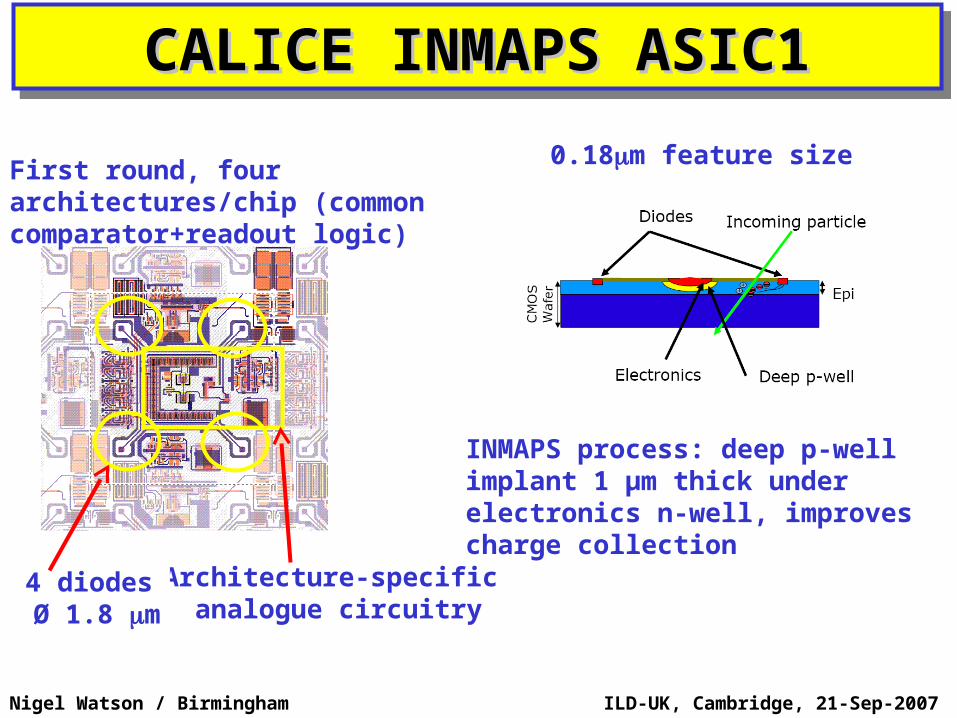
CALICE INMAPS ASIC1CALICE INMAPS ASIC1CALICE INMAPS ASIC1CALICE INMAPS ASIC1
Architecture-specific analogue circuitry
4 diodes Ø 1.8 m
First round, four architectures/chip (common comparator+readout logic)
INMAPS process: deep p-well implant 1 μm thick under electronics n-well, improves charge collection
0.18m feature size
ILD-UK, Cambridge, 21-Sep-2007Nigel Watson / Birmingham
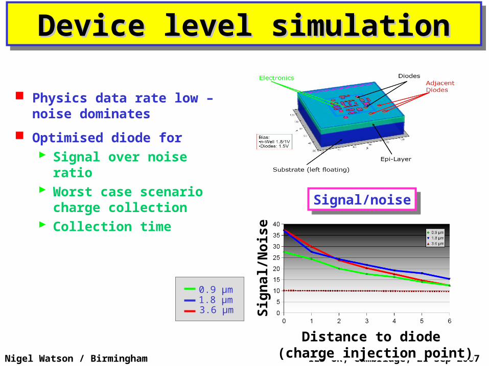
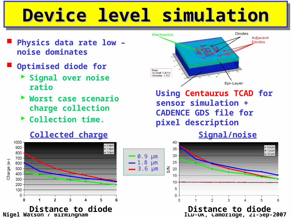
Physics data rate low – noise dominates
Optimised diode for Signal over noise ratio Worst case scenario
charge collection Collection time
Device level simulationDevice level simulationDevice level simulationDevice level simulation
Signal/noiseSignal/noise
0.9 μm1.8 μm3.6 μm
Distance to diode (charge injection point)
Sig
nal/
Nois
e
ILD-UK, Cambridge, 21-Sep-2007Nigel Watson / Birmingham
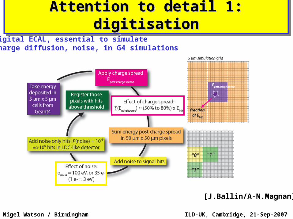
Attention to detail 1: digitisationAttention to detail 1: digitisationAttention to detail 1: digitisationAttention to detail 1: digitisation
[J.Ballin/A-M.Magnan]
Digital ECAL, essential to simulatecharge diffusion, noise, in G4 simulations
ILD-UK, Cambridge, 21-Sep-2007Nigel Watson / Birmingham
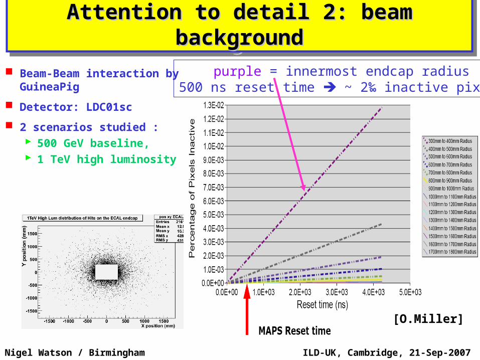
Attention to detail 2: beam Attention to detail 2: beam backgroundbackground
Attention to detail 2: beam Attention to detail 2: beam backgroundbackground
Beam-Beam interaction by GuineaPig
Detector: LDC01sc
2 scenarios studied : 500 GeV baseline, 1 TeV high luminosity
purple = innermost endcap radius500 ns reset time ~ 2‰ inactive pixels
[O.Miller]
ILD-UK, Cambridge, 21-Sep-2007Nigel Watson / Birmingham
Near future plansNear future plansNear future plansNear future plans
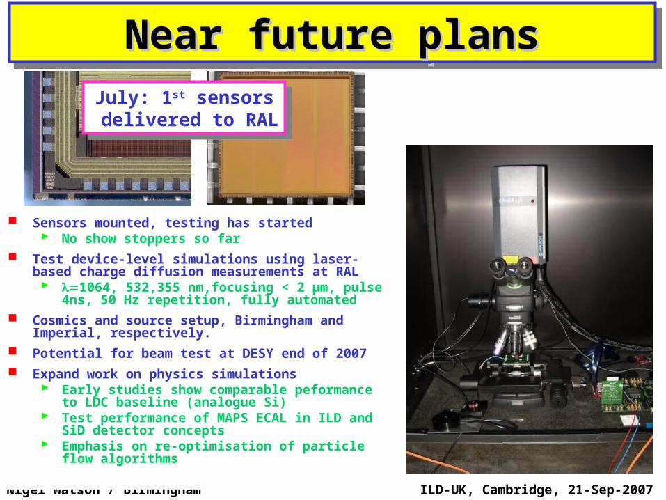
Sensors mounted, testing has started No show stoppers so far
Test device-level simulations using laser-based charge diffusion measurements at RAL 1064, 532,355 nm,focusing < 2 μm, pulse
4ns, 50 Hz repetition, fully automated Cosmics and source setup, Birmingham and
Imperial, respectively. Potential for beam test at DESY end of 2007 Expand work on physics simulations
Early studies show comparable peformance to LDC baseline (analogue Si)
Test performance of MAPS ECAL in ILD and SiD detector concepts
Emphasis on re-optimisation of particle flow algorithms
July: 1st sensors delivered to RAL
July: 1st sensors delivered to RAL
ILD-UK, Cambridge, 21-Sep-2007Nigel Watson / Birmingham
SummarySummarySummarySummary UK well placed to play big part in ILD
Make use of large CALICE datasets to optimise detector design Test hadronic models / reduce dependence on MC model unknowns Design detectors that we have proven we can build Cannot test complete PFA algorithms directly with testbeam data –
but can examine some key areas, e.g. fragment removal, etc. Physics studies for LoI
Two mature examples already, others in preparation, more essential! Easy to get involved, quick start up with ILC s/w framework, PFA
“local” expertise/assistance available PandoraPFA
The most performant PFA so far Essential tool for ILD (+other) concepts – but needs further development
and optimisation …and people – from where?
ECAL senstive detector: alternative to (LDC) baseline SiW CMOS MAPS digital ECAL for ILC
Multi-vendors, cost/performance gains New INMAPS deep p-well process (optimise charge collection) Four architectures for sensor on first chips, delivered to RAL Jul 2007 Tests of sensor performance, charge diffusion to start in August Physics benchmark studies with MAPS ECAL to evaluate performance
relative to standard analogue Si-W designs, for both SiD and LDC detector concepts
Now is a good time to join ILC detector concept study
ILD-UK, Cambridge, 21-Sep-2007Nigel Watson / Birmingham
Backup slides…Backup slides…Backup slides…Backup slides…
ILD-UK, Cambridge, 21-Sep-2007Nigel Watson / Birmingham
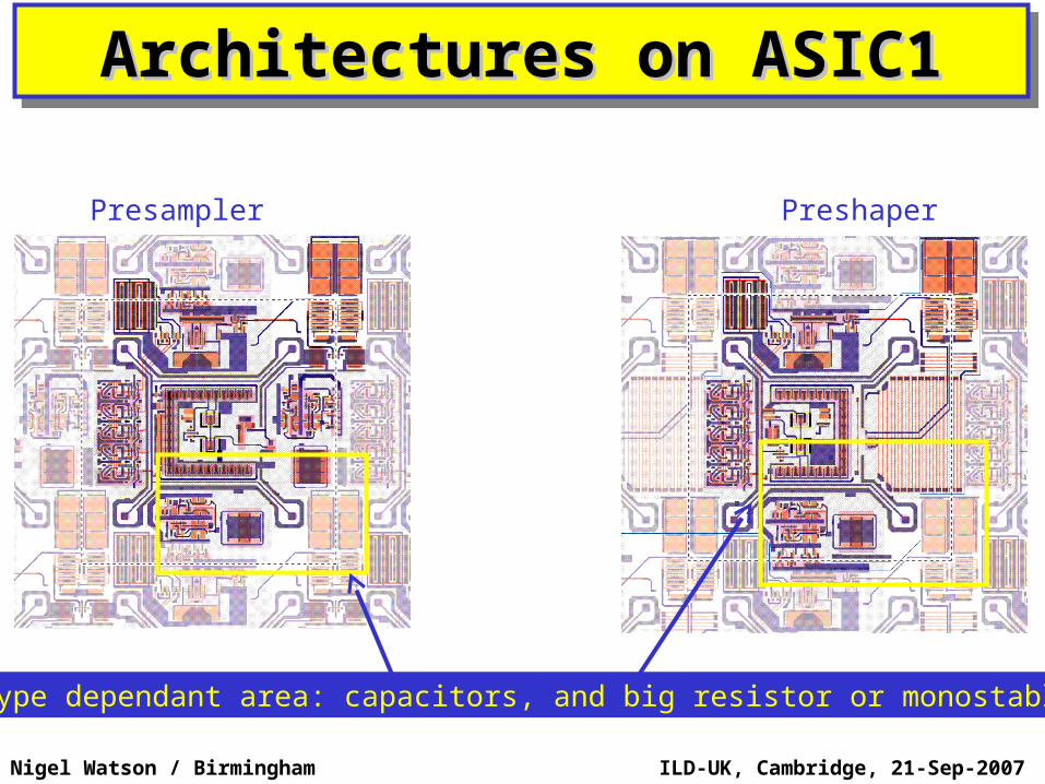
Architectures on ASIC1Architectures on ASIC1Architectures on ASIC1Architectures on ASIC1
Presampler Preshaper
Type dependant area: capacitors, and big resistor or monostable
Nigel Watson / Birmingham
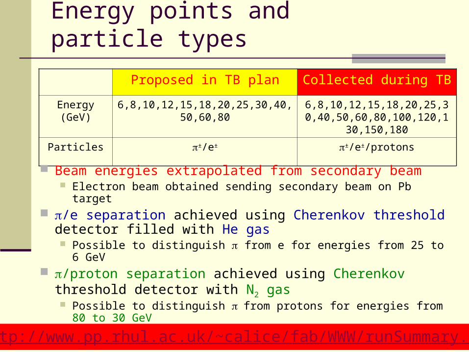
Energy points and particle types
Proposed in TB plan Collected during TB
Energy (GeV) 6,8,10,12,15,18,20,25,30,40,50,60,80 6,8,10,12,15,18,20,25,30,40,50,60,80,100,120,130,150,180
Particles ±/e± ±/e±/protons
Beam energies extrapolated from secondary beam Electron beam obtained sending secondary beam on Pb target
/e separation achieved using Cherenkov threshold detector filled with He gas Possible to distinguish from e for energies from 25 to 6 GeV
/proton separation achieved using Cherenkov threshold detector with N2 gas Possible to distinguish from protons for energies from 80 to 30
GeV
http://www.pp.rhul.ac.uk/~calice/fab/WWW/runSummary.htm
Nigel Watson / Birmingham
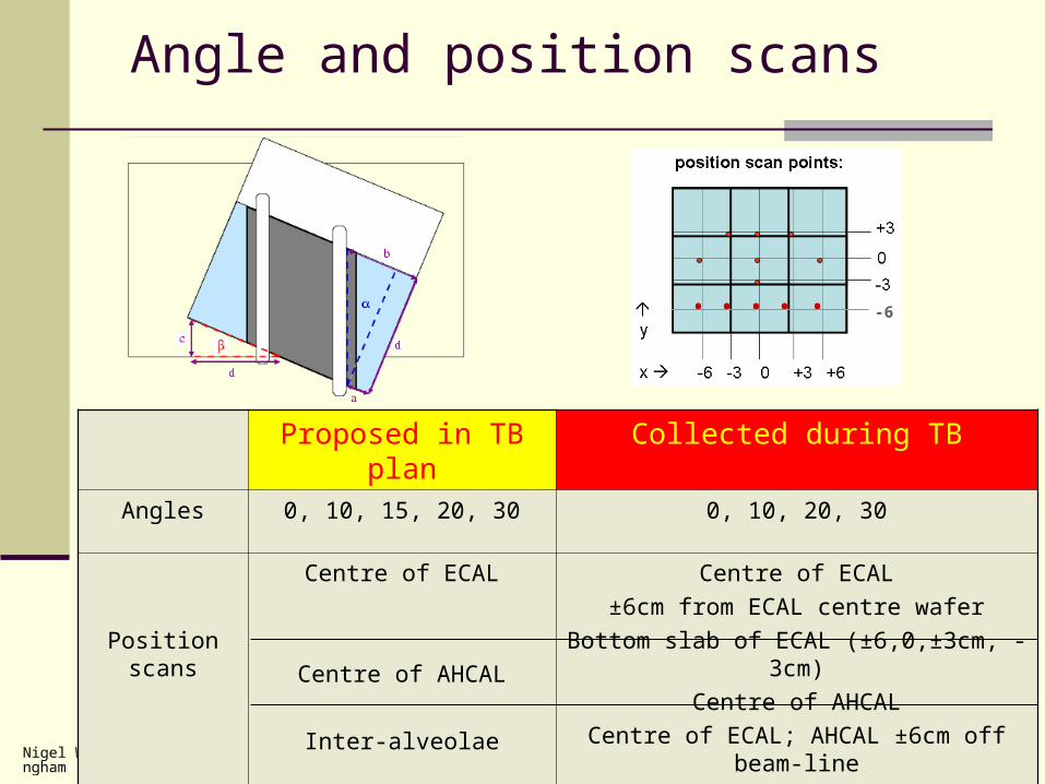
Angle and position scans
Proposed in TB plan Collected during TB
Angles 0, 10, 15, 20, 30 0, 10, 20, 30
Position scans
Centre of ECAL
Centre of AHCAL
Inter-alveolae
Centre of ECAL
±6cm from ECAL centre wafer
Bottom slab of ECAL (±6,0,±3cm, -3cm)
Centre of AHCAL
Centre of ECAL; AHCAL ±6cm off beam-line
Inter-alveolae (±3cm, ±3cm)
• • • • • -6
Nigel Watson / Birmingham
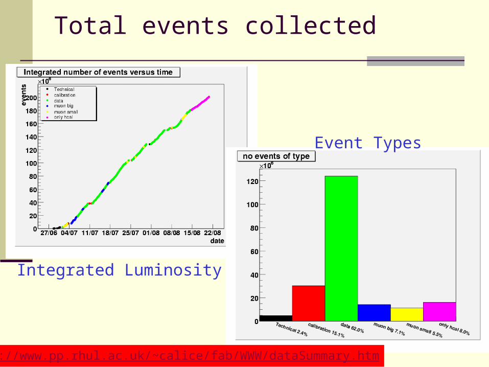
Total events collected
Integrated Luminosity
Event Types
http://www.pp.rhul.ac.uk/~calice/fab/WWW/dataSummary.htm
ILD-UK, Cambridge, 21-Sep-2007Nigel Watson / Birmingham
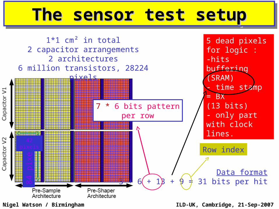
The sensor test setupThe sensor test setupThe sensor test setupThe sensor test setup5 dead pixelsfor logic :-hits buffering (SRAM)- time stamp = BX(13 bits)- only part with clock lines.
84
pix
els
42 pixels
Data format 3 + 6 + 13 + 9 = 31 bits per hit
7 * 6 bits patternper row
Row index
1*1 cm² in total2 capacitor arrangements
2 architectures6 million transistors, 28224 pixels
ILD-UK, Cambridge, 21-Sep-2007Nigel Watson / Birmingham
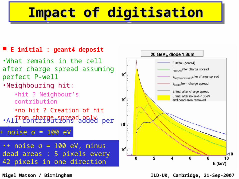
•Neighbouring hit:•hit ? Neighbour’s contribution•no hit ? Creation of hit from charge spread only
•All contributions added per pixel
•+ noise σ = 100 eV
Impact of digitisationImpact of digitisationImpact of digitisationImpact of digitisation
E initial : geant4 deposit
•What remains in the cell after charge spread assuming perfect P-well
•+ noise σ = 100 eV, minus dead areas : 5 pixels every 42 pixels in one direction
ILD-UK, Cambridge, 21-Sep-2007Nigel Watson / Birmingham
Physics data rate low – noise dominates
Optimised diode for Signal over noise ratio Worst case scenario
charge collection Collection time.
Device level simulationDevice level simulationDevice level simulationDevice level simulation
Using Centaurus TCAD for sensor simulation + CADENCE GDS file for pixel description
Signal/noiseCollected charge
0.9 μm1.8 μm3.6 μm
Distance to diodeDistance to diode