Embed Size (px)
Citation preview
Callahan Mine Superfund Site Tailing Pile Remedial Action
Design Refinement Feasibility Evaluation Memorandum
US Army Corps of Engineers - NAE
On Behalf of US Environmental Protection Agency
5/19/2017
Revised 31 May 2017
Callahan Mine Superfund Site Tailing Pile Remedial Action
Design Refinement Feasibility Evaluation
Problem Statement: A remedial design for the tailing impoundment at the Callahan Mine Superfund site was documented by AMEC in the OU3 Final Remedial Design Basis of Design Report dated 1 July 2015. The design included slope stabilization and capping of the tailing impoundment to preclude the migration of contaminants into the adjacent Goose Pond Estuary. Based on geotechnical analysis by AMEC, slope stabilization under the proposed design was achievable by lowering the dam height by 20 feet, removing 130,000 cubic yards of tailing material, constructing a drainage swale with 4H:1V side slopes within the impoundment, and installing horizontal and vertical drains to lower the water level within the tailing impoundment. The first horizontal drain was installed in August 2015. To date, the horizontal drain has not resulted in observable reduction in the water table elevation within the tailing impoundment.
Purpose of Memo: EPA requested that USACE conduct a feasibility level of analysis to determine if the tailing impoundment slope could be stabilized without complete dewatering. This memorandum documents the USACE feasibility level geotechnical evaluation of a potential refinement on the existing OU3 tailing impoundment slope stabilization design.
Key Players: The Maine Department of Transportation (DOT) is acting on behalf of the State of Maine as the Potentially Responsible Party. The Maine DOT hired a contractor (AMEC) to design the remedial approach for the Tailing Pile (Operable Unit 3 Phase I) and the Waste Rock Pile #3 (Operable Unit 3 Phase II). The US EPA is responsible for regulatory oversight of the investigation and remediation of the site. The US Army Corps of Engineers (New England District) is providing technical support to EPA for evaluating the remediation design and to implement the remediation design. USACE has not yet hired a construction contractor to perform the remediation. The Maine Department of Environmental Protection also provides regulatory oversight of the project. CES, Inc, and its subcontractor Credere Associates, provided technical assistance to Maine DEP from 2011 to 2012, culminating in a geotechnical report dated 29 February 2012.
Site Background: From 1968 through 1972, the Callahan Mining Corporation developed a massive sulfide ore body located beneath a bedrock peninsula that extended into Goose Pond. Goose Pond is a tidal estuary of approximately 75 acres located in the Town of Brooksville, ME. To gain access to the ore, the mouth of the estuary was dammed, and Goose Pond was drained. An open pit mine approximately 600 feet in diameter and 320 feet deep was excavated to access the ore. The trend of the mineralized zone was northeast- southwest, and underground workings to supplement the ore available from the pit were extended from the face of the open pit approximately 500 feet on two levels (adits) to the southwest. These adits are located approximately 120 feet below the current surface of Goose Pond. Approximately five million tons of waste rock and approximately 800,000 tons of ore-bearing rock were mined from an open-pit mine. The waste rock was disposed on-site in three large stockpiles.
1
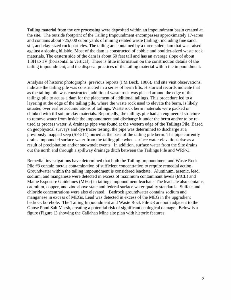
Tailing material from the ore processing were deposited within an impoundment basin created at the site. The outside footprint of the Tailing Impoundment encompasses approximately 17-acres and contains about 725,000 cubic yards of mining related waste (tailing), including fine sand, silt, and clay-sized rock particles. The tailing are contained by a three-sided dam that was raised against a sloping hillside. Most of the dam is constructed of cobble and boulder-sized waste rock materials. The eastern side of the dam is about 60 feet tall and has an average slope of about 1.3H to 1V (horizontal to vertical). There is little information on the construction details of the tailing impoundment, and the disposal practices of the tailing material within the impoundment.
Analysis of historic photographs, previous reports (FM Beck, 1986), and site visit observations, indicate the tailing pile was constructed in a series of berm lifts. Historical records indicate that as the tailing pile was constructed, additional waste rock was placed around the edge of the tailings pile to act as a dam for the placement of additional tailings. This procedure led to a layering at the edge of the tailing pile, where the waste rock used to elevate the berm, is likely situated over earlier accumulations of tailings. Waste rock berm materials were packed or chinked with till soil or clay materials. Reportedly, the tailings pile had an engineered structure to remove water from inside the impoundment and discharge it under the berm and/or to be reused as process water. A drainage pipe was found at the western edge of the Tailings Pile. Based on geophysical surveys and dye tracer testing, the pipe was determined to discharge at a previously mapped seep (SP-511) buried at the base of the tailing pile berm. The pipe currently drains impounded surface water from the tailing pile when surface water elevations rise as a result of precipitation and/or snowmelt events. In addition, surface water from the Site drains out the north end through a spillway drainage ditch between the Tailings Pile and WRP-3.
Remedial investigations have determined that both the Tailing Impoundment and Waste Rock Pile #3 contain metals contamination of sufficient concentration to require remedial action. Groundwater within the tailing impoundment is considered leachate. Aluminum, arsenic, lead, sodium, and manganese were detected in excess of maximum contaminant levels (MCL) and Maine Exposure Guidelines (MEG) in tailings impoundment leachate. The leachate also contains cadmium, copper, and zinc above state and federal surface water quality standards. Sulfate and chloride concentrations were also elevated. Bedrock groundwater contains sodium and manganese in excess of MEGs. Lead was detected in excess of the MEG in the upgradient bedrock borehole. The Tailing Impoundment and Waste Rock Pile #3 are both adjacent to the Goose Pond Salt Marsh, creating a potential risk of significant ecological damage. Below is a figure (Figure 1) showing the Callahan Mine site plan with historic features:
2
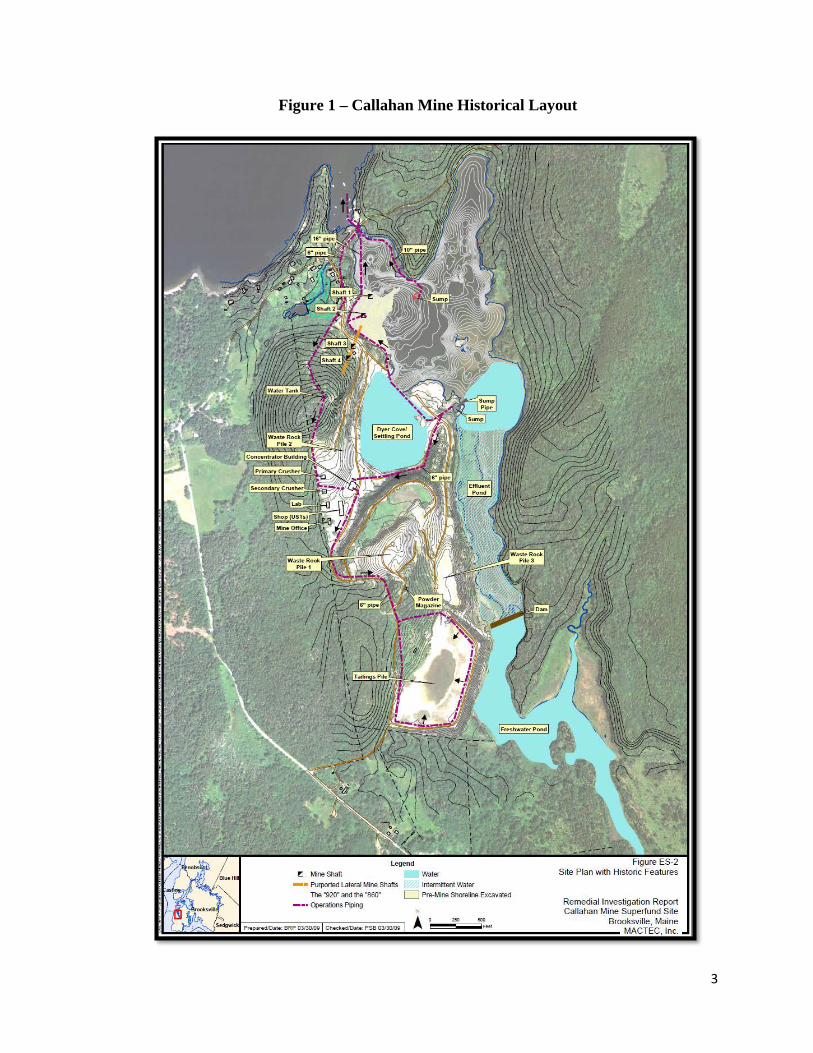
Figure 1 – Callahan Mine Historical Layout
3
Previous Geotechnical Investigations: To date, there have been three geotechnical evaluations of the tailing impoundment slope stability. The initial geotechnical evaluation was completed by MACTEC (acquired by AMEC in June 2011) in January 2009 on behalf of Maine Department of Transportation. Based on geotechnical slope stability model analysis (SLOPE/W), MACTEC determined that the existing impoundment was marginally stable under current conditions, but does not meet the applicable regulatory standard of 1.5 factor of safety. In addition, the impoundment may become unstable under seismic conditions.
Credere Associates, as a subcontractor to Charter Environmental, Inc., under contract to Maine DEP, conducted a geotechnical evaluation documented in a February 2012 report noted above. The Credere work was intended to supplement the previous MACTEC work. Specifically, the Credere objectives were to characterize the subsurface soil properties along the exterior toe of the tailing impoundment to confirm strength parameters used in the MACTEC model, characterize subsurface properties and hydrological conditions within the tailing impoundment dam, and to evaluate the static and seismic stability of placing contaminated material from the ore pad and residential properties to the top of the impoundment. In general, the soil characterization work performed by Credere corroborated the data previously collected by MACTEC. Again, the geotechnical modelling indicated that the existing slope condition does not achieve the long term slope stability factor of 1.5. Sensitivity analyses indicated that the following parameters were critical with respect to the static stability:
1) Shear strength of the normally consolidated glaciomarine silt-clay at, and under, the toe of the dam;
2) Hydrologic conditions within the tailings in the vicinity of the impoundment berm
A third geotechnical evaluation was conducted by AMEC as part of the OU3 Final Remedial Design Basis of Design Report dated 1 July 2015. In this report, AMEC evaluated the slope stability assuming implementation of the proposed remedial design. As discussed above, the remedial design includes lowering the dam height by 20 feet, removing 130,000 cubic yards of tailing material, constructing a drainage swale with 1V:4H side slopes within the impoundment, and installing horizontal and vertical drains to lower the water level within the tailing impoundment. In summary, AMEC concluded that the proposed remediation would result in achievement of long term factor of safety of greater than the regulatory standard of 1.5. In addition, AMEC concluded that the proposed remediation would result in achievement of a factor of safety of 1.24 under seismic conditions, which meets the regulatory standard for 1.0. AMEC’s conclusions that long term slope stability would be achieved under the proposed remediation is predicated on successful dewatering of the tailing impoundment.
The figure below (Figure 2) indicates the soil exploration plan conducted by Credere, and the geotechnical sections utilized to evaluate the stability of the tailing impoundment. The most critical sections were identified as Section K-K’ and Section I-I’.
4
Figure 2 – Geotechnical Sections
Tailing Impoundment Characterization: The Tailing Impoundment consists of the following principle strata: tailing (slimes, mixed, sand), clay (fill/re-worked), clay (Presumpscot Formation), and glacial till. The thickness of the tailing ranges from about 5 to 60 feet, generally increasing from west to east. Based on borings completed at the site, the tailing slimes compose approximately 50% of the Tailing Impoundment and are generally located in the central portion. The “sands” tailing consist primarily of loose silty fine-grained sand and dominate the perimeter of the impoundment. Clay fill/re-worked clay was found in areas immediately adjacent to the waste rock perimeter dam indicating that it was integral to the construction of the dam. Native clay was identified in most of the soil borings and is estimated to be widespread throughout the Tailing Impoundment footprint, but not necessarily continuous. The clay generally transitions from stiff to soft with increasing depth. The clay is typically underlain by a layer of till ranging from a few feet to almost 20 feet thick. The tailing within the impoundment are saturated, with a phreatic surface at an elevation of +70 feet on the West side decreasing to an elevation of +50 near the dam face to the east.
Although there is little documentation of the tailing impoundment construction, practices at similar mining sites indicate that slurry from the ore processing operations was delivered to the tailing dam crest and discharged from the crest at spigot locations that moved laterally and
5
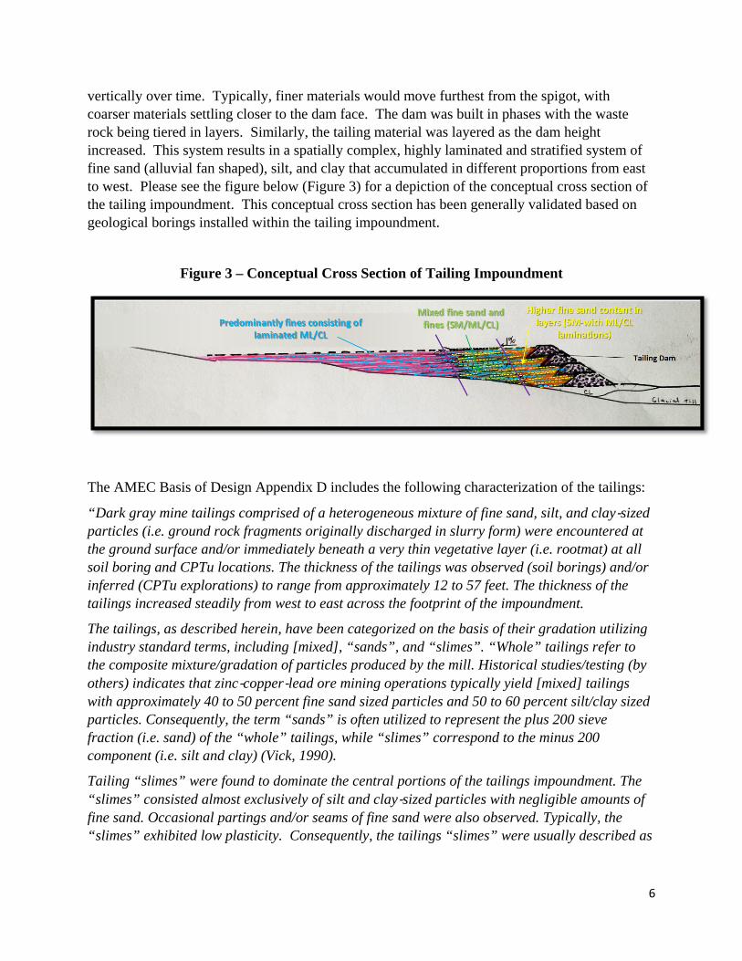
vertically over time. Typically, finer materials would move furthest from the spigot, with coarser materials settling closer to the dam face. The dam was built in phases with the waste rock being tiered in layers. Similarly, the tailing material was layered as the dam height increased. This system results in a spatially complex, highly laminated and stratified system of fine sand (alluvial fan shaped), silt, and clay that accumulated in different proportions from east to west. Please see the figure below (Figure 3) for a depiction of the conceptual cross section of the tailing impoundment. This conceptual cross section has been generally validated based on geological borings installed within the tailing impoundment.
Figure 3 – Conceptual Cross Section of Tailing Impoundment
The AMEC Basis of Design Appendix D includes the following characterization of the tailings:
“Dark gray mine tailings comprised of a heterogeneous mixture of fine sand, silt, and clay‐sized particles (i.e. ground rock fragments originally discharged in slurry form) were encountered at the ground surface and/or immediately beneath a very thin vegetative layer (i.e. rootmat) at all soil boring and CPTu locations. The thickness of the tailings was observed (soil borings) and/or inferred (CPTu explorations) to range from approximately 12 to 57 feet. The thickness of the tailings increased steadily from west to east across the footprint of the impoundment.
The tailings, as described herein, have been categorized on the basis of their gradation utilizing industry standard terms, including [mixed], “sands”, and “slimes”. “Whole” tailings refer to the composite mixture/gradation of particles produced by the mill. Historical studies/testing (by others) indicates that zinc‐copper‐lead ore mining operations typically yield [mixed] tailings with approximately 40 to 50 percent fine sand sized particles and 50 to 60 percent silt/clay sized particles. Consequently, the term “sands” is often utilized to represent the plus 200 sieve fraction (i.e. sand) of the “whole” tailings, while “slimes” correspond to the minus 200 component (i.e. silt and clay) (Vick, 1990).
Tailing “slimes” were found to dominate the central portions of the tailings impoundment. The “slimes” consisted almost exclusively of silt and clay‐sized particles with negligible amounts of fine sand. Occasional partings and/or seams of fine sand were also observed. Typically, the “slimes” exhibited low plasticity. Consequently, the tailings “slimes” were usually described as
6
“dark gray clay with some silt and trace amounts of fine sand”. A borderline unified soil classification system (USCS, ASTM D 2487) designation of CL/ML was typically applied.
Conversely, tailings characteristic of typical “whole” tailings and/or “sand” dominated the eastern edge of the deposit near the crest of the impoundment berm. The “[mixed]/sand” tailings were usually described as silty fine sand and/or fine sandy silt. However, the “[mixed]/sand” tailings were stratified with frequent partings and/or seams of tailings “slimes”, likely as a result of ponded decant water periodically encroaching upon the sand “beach” during periods of high precipitation and/or surface water flow.
Overall, SPT N‐values of the tailings ranged from 8 to less than 1 (i.e. WH or WR) within the tailings. Within the “slimes”, the range of N‐values narrowed, from 3 to less than 1. Similarly, N‐values of 3 to 5 were typical within the “[mixed]/sand” tailings.”
Presumpscot Clay Characterization:
The AMEC BOD Appendix D includes the following characterization of Presumpscot Clay:
“A relatively thin stratum of Presumpscot Clay was encountered immediately beneath the tailings in soil borings SB‐601, SB‐602, and SB‐605B and beneath the crushed rock/reworked glacial till fill material in soil boring SB‐603. Lean clay was also inferred beneath the tailings in CPTu explorations CP‐601, CP‐602, CP‐603, CP‐604, CP‐607, CP‐608, CP‐614, and CP‐615. The clay was the uppermost native stratum prior to the construction of the tailings impoundment.
The clay was encountered (soil borings) and/or inferred (CPTu explorations) at depths ranging from approximately 12 to 57 feet bgs, with depths increasing steadily from west to east. Overall, the thickness of the lean clay ranged from approximately 1 to 16 feet. Thicknesses of at least 5 feet were typically observed/inferred across the southern 1/3 of the tailing impoundment.
SPT N‐values ranged from 18 to less than 1 (i.e. WH or WR). Limited in‐situ VST yielded “peak” undrained shear strengths, Su, ranging from 350 to 700 pounds psf. Limited testing of in situ split spoon samples via a hand‐held torvane yielded shear strengths ranging from 700 to 900 psf. Similarly, pocket penetrometer testing of split‐spoon samples yielded shear strengths of 300 to 1600 psf. Consequently, the lean clay was typically described as stiff to soft, based on the recorded N‐values and the Su values. Typically, the clay transitioned from stiff to medium stiff to soft with increasing depth. The thickness of the stiff to medium stiff “crust” generally ranged from a few to several feet in thickness.”
“Consolidated Clay” Characterization:
The 2012 Credere Supplemental Geotechnical Investigation includes the following detailed characterization of “Consolidated Clay”:
“The fine-grained glaciomarine deposits are characterized by a very stiff to medium stiff, olive-brown, low plasticity, silt-clay crust overlying very soft to soft, blue-gray, silt-clay having moderate plasticity. The overlying crust is typically highly over-consolidated, with over-consolidation ratios (OCRs) greater than 4. The soft to very soft glaciomarine deposits are typically normally consolidated. Where the glaciomarine silt-clays were encountered at the Site, the thickness of the crust material (very stiff to medium stiff silt-clay) varied from 0 to 13 feet
7

overlying 0 to 27 feet of soft to very soft silt-clay. Based on undisturbed and remolded in-situ vane shear tests, the normally consolidated silt-clay is moderately sensitive.
It is generally accepted that this material gains strength when loaded as excess pore pressures dissipate and the material consolidates. When considering post-consolidation undrained shear strength, the magnitude of the strength gain is a function of the imposed load and the material’s OCR, and is defined by the SHANSEP principle. Shear strength of this material under and imposed surcharge load is accounted for in the drained, long-term condition through the use of effective strength parameters c’ and ϕ’. Shear strength values used in the stability analyses are discussed in subsequent sections of this report, with supporting documentation provided in the appendices.
At several locations within the impoundment, undisturbed glaciomarine silt-clay was not encountered. It is likely that in preparing the site for construction of the impoundment, some of the natural clay and silt was relocated to other areas either through general grading or for leveling or berm construction. In some locations, up to approximately 15 feet of reworked clay and silt was encountered, and in others, the tailings directly overlie till or bedrock. It should be noted that a thick continuous layer of soft silt-clay does not appear to be present under the impoundment. However, estimating the horizontal limits of the non-continuous glaciomarine silt-clay layer is difficult and modeling a continuous layer is a valid, but conservative assumption.”
Tailing Pile Remediation Design Background: AMEC has completed the remedial design for the Tailing Impoundment which is documented in a report dated 1 July 2015 (Cross section shown below in Figure 4). This design has been approved by EPA and DEP. The design consists of the following key elements:
- Install Eight Horizontal Drains to Dewater the Tailing Impoundment - Cut Back Tailing Dam Height by approximately 20’ to Reduce Load on Dam - Excavate Swale in Tailing to Provide Surface Drainage and Reduce Load - Re-grade Swale Material (130,000 CY) into Tailing Impoundment (4H:1V Slope) - Install EQ/Wick Drains Within Tailing Impoundment to Reduce Pore Pressure - Install Cover Over Re-Graded Tailing Impoundment - Water Management During and After Construction - Remediate Waste Rock Pile #3 Under Operable Unit 3 Phase II
Figure 4 – K-Line Current Design – Swale at 4H:1V
8
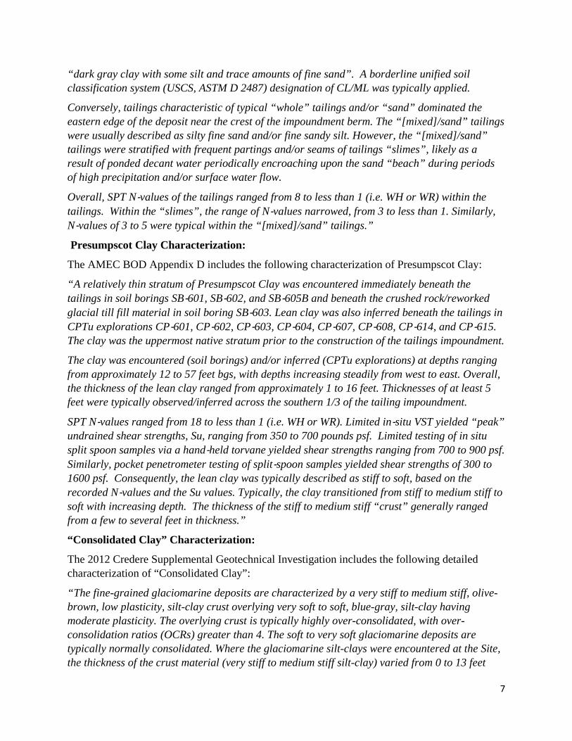
Structural Stability Analysis: As discussed above, the tailing impoundment was evaluated by AMEC for structural stability under conditions before, during, and after the remediation is completed. The remedial design was evaluated for slope stability using SLOPE/W for several cross-sections under long term static conditions, construction load, pseudo-static conditions, and seismic conditions. The input parameters, assumptions, and model run results are documented in the OU3 Final Design – Basis of Design Report and in Appendices C and D of the report. In summary, the existing tailing impoundment dam is marginally stable under current conditions (minimum FOS of 1.03), but does not meet the regulatory standard of 1.5 for long term stability. In addition, under seismic conditions, the Tailing Impoundment may become unstable (FOS <1.0). The report concluded that, during construction, heavy equipment should not be operated within 10 feet of the crest of the dam. After the remediation is complete, AMEC estimated the following minimum FOS for each key cross section:
Table 1 – Summary of AMEC Long Term Static FOS Current Design Post Remediation
• Note that Profile E2 is analogous to Section I-I’, and Profile E-3 is analogous to Section K-K’, in 2012 Credere Report
The post remediation stability was also evaluated under seismic conditions. Under the pseudo-static condition, the slope stability for the worst case condition (Impoundment Dam Crest to Toe) was evaluated for each cross section. In this analysis, the minimum estimated FOS was 1.01 for cross-section E3. The post-earthquake slope stability was also evaluated for cross section E3. Under this analysis, a FOS of 1.24 was estimated under post remediation conditions. The AMEC slope stability was calculated assuming that the Tailing Impoundment is successfully dewatered after the remediation is completed. Assuming that the Tailing Impoundment is not fully dewatered (water elevation at 41’), the estimated long term static FOS decreases from 1.50 to 1.40 for the Dam Crest to Dam Toe along the most critical cross section (E3).
9
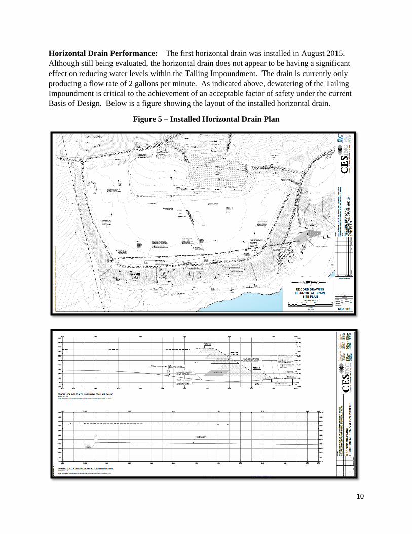
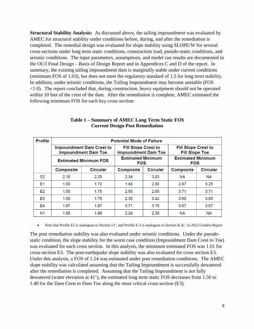
Horizontal Drain Performance: The first horizontal drain was installed in August 2015. Although still being evaluated, the horizontal drain does not appear to be having a significant effect on reducing water levels within the Tailing Impoundment. The drain is currently only producing a flow rate of 2 gallons per minute. As indicated above, dewatering of the Tailing Impoundment is critical to the achievement of an acceptable factor of safety under the current Basis of Design. Below is a figure showing the layout of the installed horizontal drain.
Figure 5 – Installed Horizontal Drain Plan
10
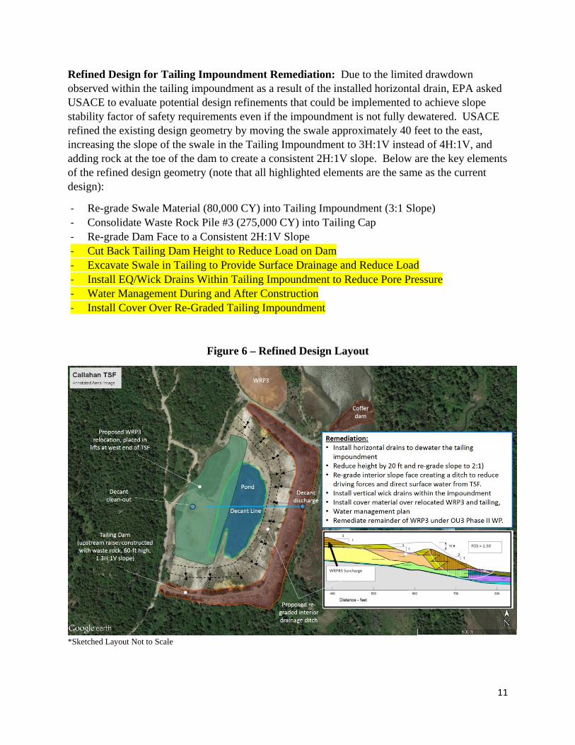
Refined Design for Tailing Impoundment Remediation: Due to the limited drawdown observed within the tailing impoundment as a result of the installed horizontal drain, EPA asked USACE to evaluate potential design refinements that could be implemented to achieve slope stability factor of safety requirements even if the impoundment is not fully dewatered. USACE refined the existing design geometry by moving the swale approximately 40 feet to the east, increasing the slope of the swale in the Tailing Impoundment to 3H:1V instead of 4H:1V, and adding rock at the toe of the dam to create a consistent 2H:1V slope. Below are the key elements of the refined design geometry (note that all highlighted elements are the same as the current design):
- Re-grade Swale Material (80,000 CY) into Tailing Impoundment (3:1 Slope) - Consolidate Waste Rock Pile #3 (275,000 CY) into Tailing Cap - Re-grade Dam Face to a Consistent 2H:1V Slope - Cut Back Tailing Dam Height to Reduce Load on Dam - Excavate Swale in Tailing to Provide Surface Drainage and Reduce Load - Install EQ/Wick Drains Within Tailing Impoundment to Reduce Pore Pressure - Water Management During and After Construction - Install Cover Over Re-Graded Tailing Impoundment
Figure 6 – Refined Design Layout
*Sketched Layout Not to Scale
11
The refined design geometry results in a reduced load on the dam wall due to the removal of sand tailing material in closer proximity to the dam crest (`40 feet further east). The steeper slope of the swale reduces the amount of tailing material that needs to be excavated from 130,000 CY to approximately 80,000 CY. In addition, the swale excavation is in the coarser tailing material, which are generally drier and easier to manage. As seen in the cross section above, the water elevation within the tailing impoundment increases from east to west. The lowest point of the drainage swale would be approximately the same under both designs (elevation of 50 feet).
Another benefit of the revised configuration is that there would be increased capacity within the tailing impoundment cover to consolidate contaminated material. With this increased capacity, the material from Waste Rock Pile#3 could be consolidated within the cover with only a moderate increase in elevation. The design in the July 2015 Basis of Design had a maximum elevation of 94’ MSL. The refined geometry results in an increase of approximately 24 feet to an elevation of approximately 100’ MSL. Both elevations provided are prior to cap placement and pre-settlement. Although the amount of material being placed is greater (due to the placement of the waste rock material), it is somewhat offset by the movement of the swale further east and the reduced slope of the swale (from 4H:1V to 3H:1V). In combination, these two factors create additional capacity on top of the existing impoundment without a significant increase in the elevation of the final cap.
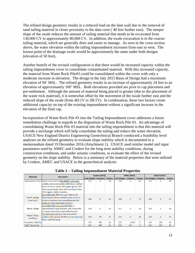
Incorporation of Waste Rock Pile #3 into the Tailing Impoundment cover addresses a future remediation challenge in regards to the disposition of Waste Rock Pile #3. An advantage of consolidating Waste Rock Pile #3 material into the tailing impoundment is that this material will provide a surcharge which will help consolidate the tailing and reduce the water elevation. USACE New England District Engineering Geotechnical Branch conducted a feasibility level analyses on the refined geometry to evaluate slope stability which is documented in a memorandum dated 19 December 2016 (Attachment 1). USACE used similar model and input parameters used by AMEC and Credere for the long term stability conditions, during construction conditions, and under seismic conditions, to evaluate the effect of the revised geometry on the slope stability. Below is a summary of the material properties that were utilized by Credere, AMEC and USACE in the geotechnical analysis:
Table 2 – Tailing Impoundment Material Properties
12
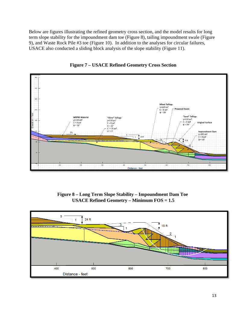
Below are figures illustrating the refined geometry cross section, and the model results for long term slope stability for the impoundment dam toe (Figure 8), tailing impoundment swale (Figure 9), and Waste Rock Pile #3 toe (Figure 10). In addition to the analyses for circular failures, USACE also conducted a sliding block analysis of the slope stability (Figure 11).
Figure 7 – USACE Refined Geometry Cross Section
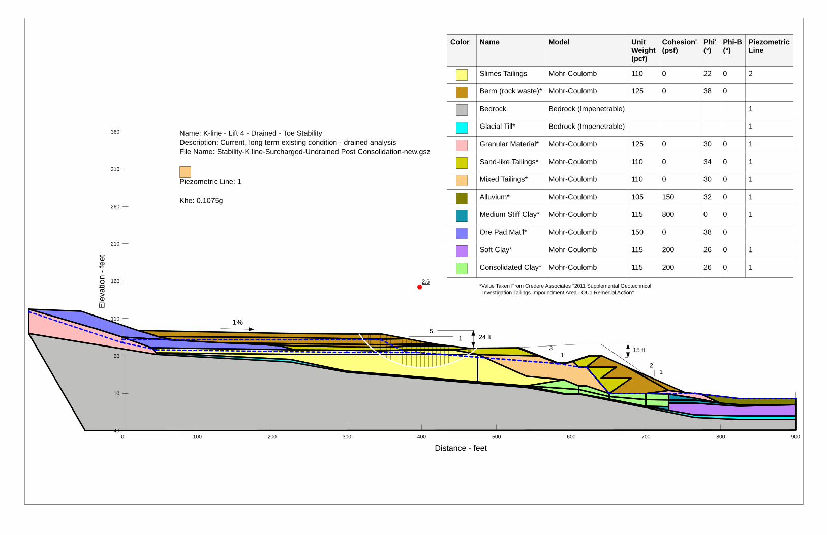
Figure 8 – Long Term Slope Stability – Impoundment Dam Toe USACE Refined Geometry – Minimum FOS = 1.5
13
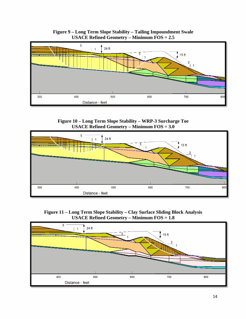
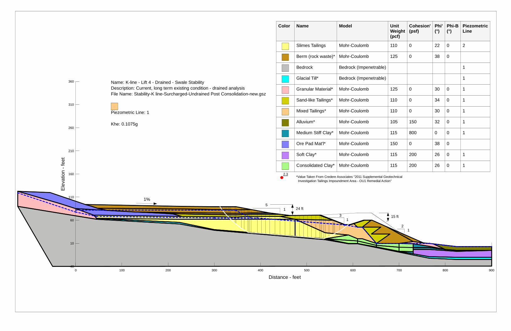
Figure 9 – Long Term Slope Stability – Tailing Impoundment Swale USACE Refined Geometry – Minimum FOS = 2.5
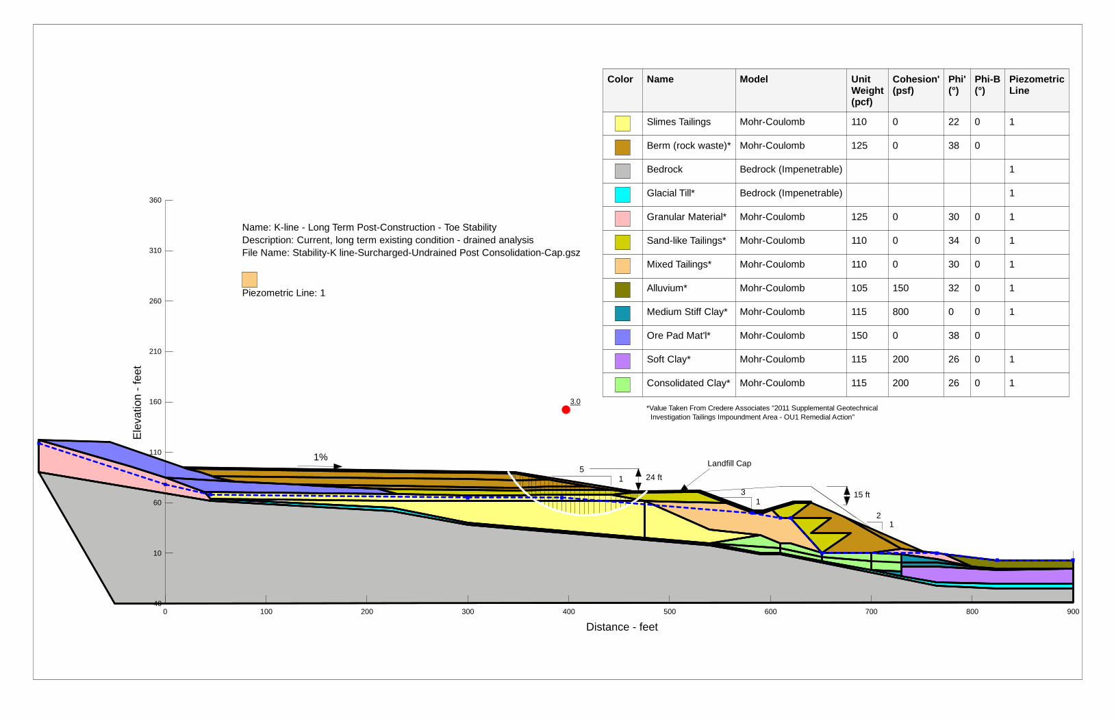
Figure 10 – Long Term Slope Stability – WRP-3 Surcharge Toe USACE Refined Geometry – Minimum FOS = 3.0
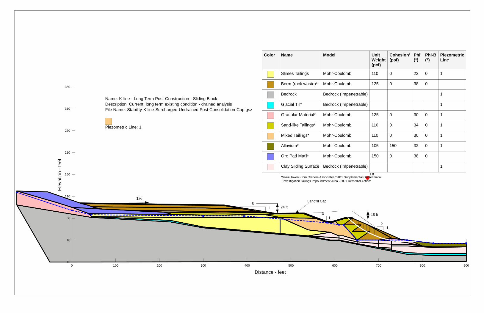
Figure 11 – Long Term Slope Stability – Clay Surface Sliding Block Analysis USACE Refined Geometry – Minimum FOS = 1.8
14
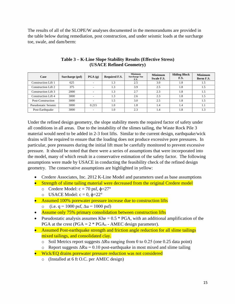
The results of all of the SLOPE/W analyses documented in the memorandums are provided in the table below during remediation, post construction, and under seismic loads at the surcharge toe, swale, and dam/berm:
Table 3 – K-Line Slope Stability Results (Effective Stress) (USACE Refined Geometry)
Case Surcharge (psf) PGA (g) Required F.S. Minimum
Surcharge Toe F.S.
Minimum Swale F.S.
Sliding Block F.S.
Minimum Berm F.S.
Construction Lift 1 625 - 1.3 2.5 3.0 1.8 1.5 Construction Lift 2 375 - 1.3 3.9 2.5 1.8 1.5 Construction Lift 3 2000 - 1.3 2.7 2.3 1.8 1.5 Construction Lift 4 3000 - 1.3 2.6 2.3 1.8 1.5 Post-Construction 3000 - 1.5 3.0 2.5 1.8 1.5
Pseudostatic Seismic 3000 0.215 1.0 1.8 1.4 1.4 1.1 Post-Earthquake 3000 - 1.0 2.3 1.4 1.8 1.3
Under the refined design geometry, the slope stability meets the required factor of safety under all conditions in all areas. Due to the instability of the slimes tailing, the Waste Rock Pile 3 material would need to be added in 2-3 foot lifts. Similar to the current design, earthquake/wick drains will be required to ensure that the loading does not produce excessive pore pressures. In particular, pore pressures during the initial lift must be carefully monitored to prevent excessive pressure. It should be noted that there were a series of assumptions that were incorporated into the model, many of which result in a conservative estimation of the safety factor. The following assumptions were made by USACE in conducting the feasibility check of the refined design geometry. The conservative assumptions are highlighted in yellow:
• Credere Associates, Inc. 2012 K-Line Model and parameters used as base assumptions • Strength of slime tailing material were decreased from the original Credere model
o Credere Model: c = 70 psf, ɸ=27° o USACE Model: c = 0, ɸ=22°
• Assumed 100% porewater pressure increase due to construction lifts o (i.e. q = 1000 psf, Δu = 1000 psf)
• Assume only 75% primary consolidation between construction lifts • Pseudostatic analysis assumes Khe = 0.5 * PGA, with an additional amplification of the
PGA at the crest (PGA = 2 * PGAo - AMEC design parameter). • Assumed Post-earthquake strength and friction angle reduction for all slime tailings
mixed tailings, and consolidated clay. o Soil Metrics report suggests ΔRu ranging from 0 to 0.25 (one 0.25 data point) o Report suggests ΔRu = 0.10 post-earthquake in most mixed and slime tailing
• Wick/EQ drains porewater pressure reduction was not considered o (Installed at 6 ft O.C. per AMEC design)
15
Under the refined design geometry, the dam face slope would be decreased from the current 1.67H:1V in the worst case condition to 2H:1V for the entire length of the dam. The relaxed slope condition results in a more stable dam against deep failures, and is also more protective against shallow unravelling of the rock that may occur in the slope face over time. The change in slope would result in an increase in the toe footprint by approximately 20 feet to the east. There would be permanent loss of wetlands as a result of the increased footprint of the toe (approximately 20,000 SF).
Stability Check Using Undrained Shear Strength Parameters
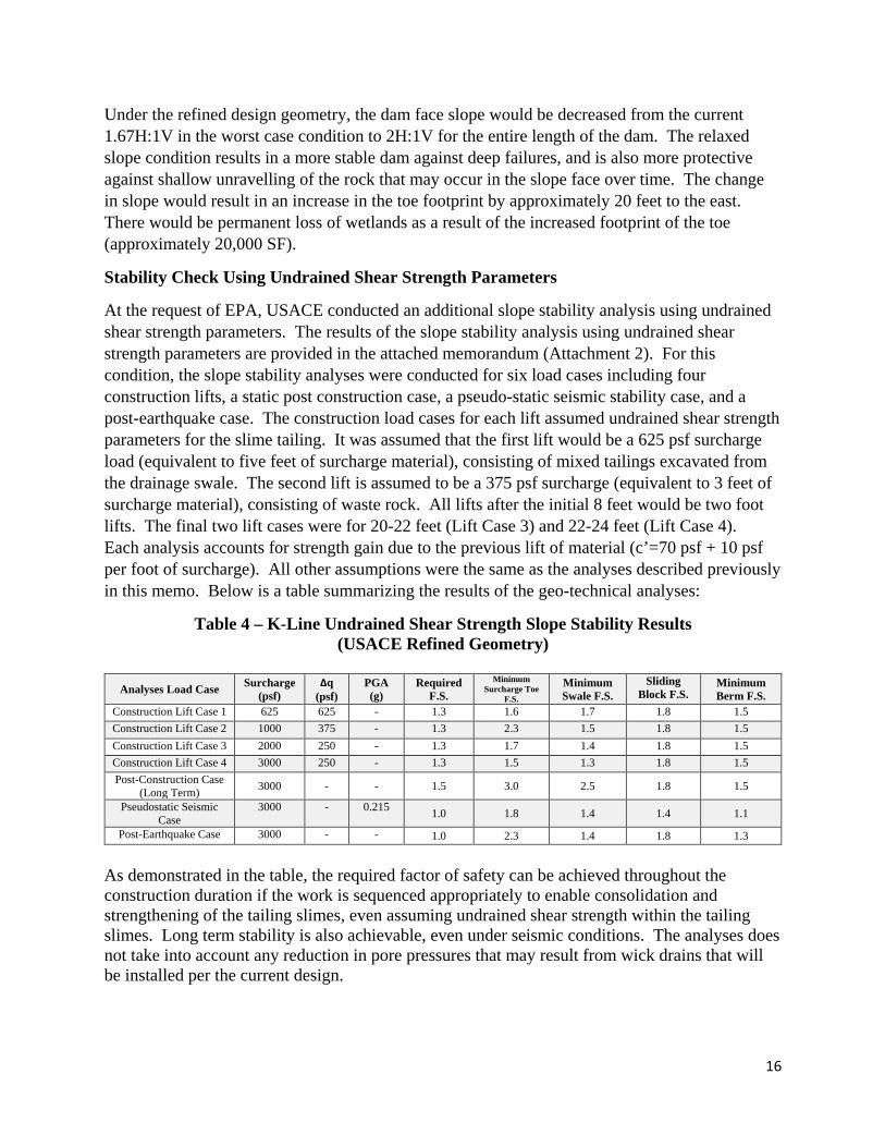
At the request of EPA, USACE conducted an additional slope stability analysis using undrained shear strength parameters. The results of the slope stability analysis using undrained shear strength parameters are provided in the attached memorandum (Attachment 2). For this condition, the slope stability analyses were conducted for six load cases including four construction lifts, a static post construction case, a pseudo-static seismic stability case, and a post-earthquake case. The construction load cases for each lift assumed undrained shear strength parameters for the slime tailing. It was assumed that the first lift would be a 625 psf surcharge load (equivalent to five feet of surcharge material), consisting of mixed tailings excavated from the drainage swale. The second lift is assumed to be a 375 psf surcharge (equivalent to 3 feet of surcharge material), consisting of waste rock. All lifts after the initial 8 feet would be two foot lifts. The final two lift cases were for 20-22 feet (Lift Case 3) and 22-24 feet (Lift Case 4). Each analysis accounts for strength gain due to the previous lift of material (c’=70 psf + 10 psf per foot of surcharge). All other assumptions were the same as the analyses described previously in this memo. Below is a table summarizing the results of the geo-technical analyses:
Table 4 – K-Line Undrained Shear Strength Slope Stability Results (USACE Refined Geometry)
Analyses Load Case Surcharge (psf)
Δq (psf)
PGA (g)
Required F.S.
Minimum Surcharge Toe
F.S.
Minimum Swale F.S.
Sliding Block F.S.
Minimum Berm F.S.
Construction Lift Case 1 625 625 - 1.3 1.6 1.7 1.8 1.5 Construction Lift Case 2 1000 375 - 1.3 2.3 1.5 1.8 1.5 Construction Lift Case 3 2000 250 - 1.3 1.7 1.4 1.8 1.5 Construction Lift Case 4 3000 250 - 1.3 1.5 1.3 1.8 1.5 Post-Construction Case
(Long Term) 3000 - - 1.5 3.0 2.5 1.8 1.5
Pseudostatic Seismic Case
3000 - 0.215 1.0 1.8 1.4 1.4 1.1
Post-Earthquake Case 3000 - - 1.0 2.3 1.4 1.8 1.3
As demonstrated in the table, the required factor of safety can be achieved throughout the construction duration if the work is sequenced appropriately to enable consolidation and strengthening of the tailing slimes, even assuming undrained shear strength within the tailing slimes. Long term stability is also achievable, even under seismic conditions. The analyses does not take into account any reduction in pore pressures that may result from wick drains that will be installed per the current design.
16
Basis of Design – Tailing Impoundment Water Management
Although the geotechnical analyses conducted by USACE assumes that the tailing impoundment is not dewatered, and there is no subsequent relief of pore pressure, the design actually includes a network of vertical drains that will be installed within the tailing impoundment. The vertical drains are designed to be installed at a 6 foot triangular spacing. The vertical drains will be tied into a drainage layer that will direct the water into the drainage swale and/or sumps. Surface water upgradient of the tailing impoundment will be diverted around the tailing impoundment. Surface water from within the footprint of the tailing impoundment will be collected within the drainage swale created within the tailing impoundment. All water collected from the vertical drains and the surface water will be treated within the bioreactor facility.
The vertical drains are designed to achieve several objectives:
1) reduce pore pressure within the tailing impoundment during placement of tailing material (and/or waste rock) on top of the impoundment
2) reduce time to achieve 90% consolidation during lift placement 3) reduce water elevation within the impoundment
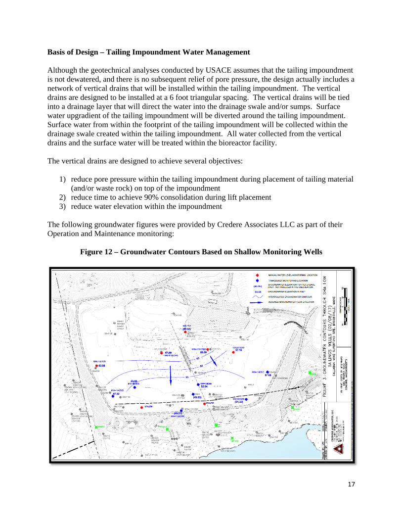
The following groundwater figures were provided by Credere Associates LLC as part of their Operation and Maintenance monitoring:
Figure 12 – Groundwater Contours Based on Shallow Monitoring Wells
17
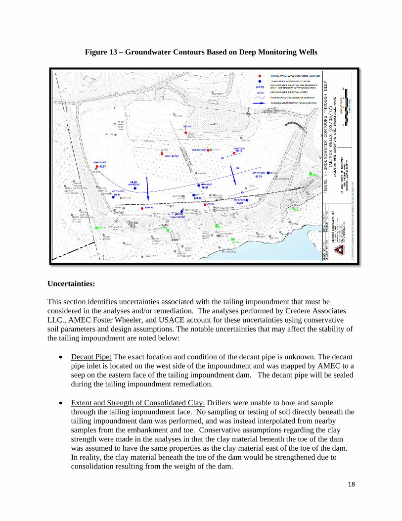
Figure 13 – Groundwater Contours Based on Deep Monitoring Wells
Uncertainties:
This section identifies uncertainties associated with the tailing impoundment that must be considered in the analyses and/or remediation. The analyses performed by Credere Associates LLC., AMEC Foster Wheeler, and USACE account for these uncertainties using conservative soil parameters and design assumptions. The notable uncertainties that may affect the stability of the tailing impoundment are noted below:
• Decant Pipe: The exact location and condition of the decant pipe is unknown. The decant pipe inlet is located on the west side of the impoundment and was mapped by AMEC to a seep on the eastern face of the tailing impoundment dam. The decant pipe will be sealed during the tailing impoundment remediation.
• Extent and Strength of Consolidated Clay: Drillers were unable to bore and sample through the tailing impoundment face. No sampling or testing of soil directly beneath the tailing impoundment dam was performed, and was instead interpolated from nearby samples from the embankment and toe. Conservative assumptions regarding the clay strength were made in the analyses in that the clay material beneath the toe of the dam was assumed to have the same properties as the clay material east of the toe of the dam. In reality, the clay material beneath the toe of the dam would be strengthened due to consolidation resulting from the weight of the dam.
18
• Impoundment Construction Detail: Few documents detailing the construction of the tailing impoundment exist. The extent of the tailing impoundment dam lifts are based on investigatory borings and limited sketches that exist from original construction. Additional information regarding the impoundment construction will become evident during the excavation of the swale in the impoundment.
• Unknown Internal Geologic Variability: Based on surviving historical documents from the mine, and previously performed investigatory borings, the tailings material was placed hydraulically. However, the extent of layering and inter-bedding of mixed, sand, and slime tailings is unknown. It is also unknown at what frequency the hydraulic delivery system was lifted, moved, or shut down. The model cross sections provided assume an ideal separation of tailings material, and do not illustrate or consider thin inter-bedding of tailing material. Additional information regarding the impoundment geologic variability will become evident during the excavation of the swale in the impoundment.
• Phreatic Surface Beneath Tailing Impoundment Dam: Sampling and installation of observation wells through the tailing impoundment dam was not feasible. The phreatic surface beneath the tailing impoundment dam was interpolated based on nearby investigatory borings, ground water sampling, as well as the assumed soil properties.
Conclusion: Based on the analyses completed to date, the refined geometry as evaluated by USACE is feasible to achieve the regulatory slope stability factor of safety both during and after the construction duration, even if the tailing impoundment is not fully de-watered. It may be possible to further optimize the design geometry by moving the swale more easterly resulting in even lower loading on the dam and increased capacity within the cover system. Under the Performance Based Contract, the Remediation Contractor will be responsible to ensure that the regulatory FOS is maintained both during remediation and post remediation. In addition, the Remediation Contractor must ensure that the regulatory factor of safety under seismic conditions is also achieved. Extensive geotechnical monitoring will be required before, during, and after the remediation by the Remediation Contractor to ensure that the tailing impoundment achieves and maintains regulatory stability requirements. The Remediation Contractor will be required to submit a Geotechnnical Monitoring Plan to identify the instrumentation and monitoring that will be implemented during the remediation. In addition, the Remediation Contractor will be required to submit a Work Plan for all proposed work to document the proposed approach, and the means and methods to complete the required work. The Geotechnical Monitoring Plan and the Work Plan will be submitted to all stakeholders for review.
19
CENAE-EDW December 19, 2016 Revised May 30, 2017
Andryuk x071 MEMORANDUM FOR RECORD
SUBJECT: Callahan Mine Alternative 2 Slope Stability
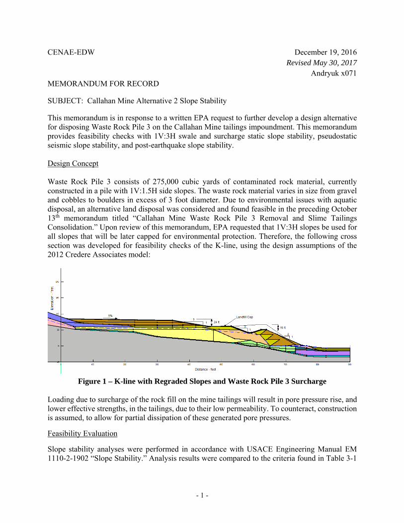
This memorandum is in response to a written EPA request to further develop a design alternative for disposing Waste Rock Pile 3 on the Callahan Mine tailings impoundment. This memorandum provides feasibility checks with 1V:3H swale and surcharge static slope stability, pseudostatic seismic slope stability, and post-earthquake slope stability.
Design Concept
Waste Rock Pile 3 consists of 275,000 cubic yards of contaminated rock material, currently constructed in a pile with 1V:1.5H side slopes. The waste rock material varies in size from gravel and cobbles to boulders in excess of 3 foot diameter. Due to environmental issues with aquatic disposal, an alternative land disposal was considered and found feasible in the preceding October 13th memorandum titled “Callahan Mine Waste Rock Pile 3 Removal and Slime Tailings Consolidation.” Upon review of this memorandum, EPA requested that 1V:3H slopes be used for all slopes that will be later capped for environmental protection. Therefore, the following cross section was developed for feasibility checks of the K-line, using the design assumptions of the 2012 Credere Associates model:
Figure 1 – K-line with Regraded Slopes and Waste Rock Pile 3 Surcharge
Loading due to surcharge of the rock fill on the mine tailings will result in pore pressure rise, and lower effective strengths, in the tailings, due to their low permeability. To counteract, construction is assumed, to allow for partial dissipation of these generated pore pressures.
Feasibility Evaluation
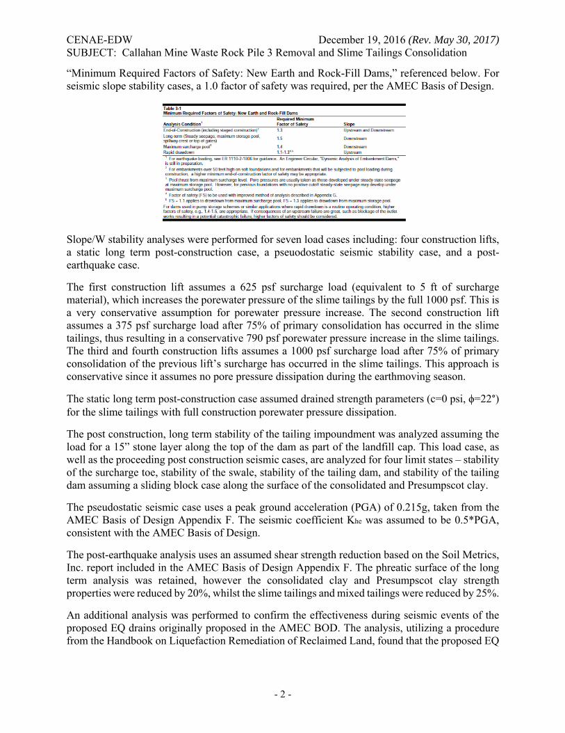
Slope stability analyses were performed in accordance with USACE Engineering Manual EM 1110-2-1902 “Slope Stability.” Analysis results were compared to the criteria found in Table 3-1
- 1 -
CENAE-EDW December 19, 2016 (Rev. May 30, 2017) SUBJECT: Callahan Mine Waste Rock Pile 3 Removal and Slime Tailings Consolidation
“Minimum Required Factors of Safety: New Earth and Rock-Fill Dams,” referenced below. For seismic slope stability cases, a 1.0 factor of safety was required, per the AMEC Basis of Design.
Slope/W stability analyses were performed for seven load cases including: four construction lifts, a static long term post-construction case, a pseuodostatic seismic stability case, and a post-earthquake case.
The first construction lift assumes a 625 psf surcharge load (equivalent to 5 ft of surcharge material), which increases the porewater pressure of the slime tailings by the full 1000 psf. This is a very conservative assumption for porewater pressure increase. The second construction lift assumes a 375 psf surcharge load after 75% of primary consolidation has occurred in the slime tailings, thus resulting in a conservative 790 psf porewater pressure increase in the slime tailings. The third and fourth construction lifts assumes a 1000 psf surcharge load after 75% of primary consolidation of the previous lift’s surcharge has occurred in the slime tailings. This approach is conservative since it assumes no pore pressure dissipation during the earthmoving season.
The static long term post-construction case assumed drained strength parameters (c=0 psi, ϕ=22°) for the slime tailings with full construction porewater pressure dissipation.
The post construction, long term stability of the tailing impoundment was analyzed assuming the load for a 15” stone layer along the top of the dam as part of the landfill cap. This load case, as well as the proceeding post construction seismic cases, are analyzed for four limit states – stability of the surcharge toe, stability of the swale, stability of the tailing dam, and stability of the tailing dam assuming a sliding block case along the surface of the consolidated and Presumpscot clay.
The pseudostatic seismic case uses a peak ground acceleration (PGA) of 0.215g, taken from the AMEC Basis of Design Appendix F. The seismic coefficient Khe was assumed to be 0.5*PGA, consistent with the AMEC Basis of Design.
The post-earthquake analysis uses an assumed shear strength reduction based on the Soil Metrics, Inc. report included in the AMEC Basis of Design Appendix F. The phreatic surface of the long term analysis was retained, however the consolidated clay and Presumpscot clay strength properties were reduced by 20%, whilst the slime tailings and mixed tailings were reduced by 25%.
An additional analysis was performed to confirm the effectiveness during seismic events of the proposed EQ drains originally proposed in the AMEC BOD. The analysis, utilizing a procedure from the Handbook on Liquefaction Remediation of Reclaimed Land, found that the proposed EQ
- 2 -
CENAE-EDW December 19, 2016 (Rev. May 30, 2017) SUBJECT: Callahan Mine Waste Rock Pile 3 Removal and Slime Tailings Consolidation
drains would have no substantial reduction in porewater pressure build up during a seismic event. The effects of EQ drains were therefore not included in the post-earthquake analysis.
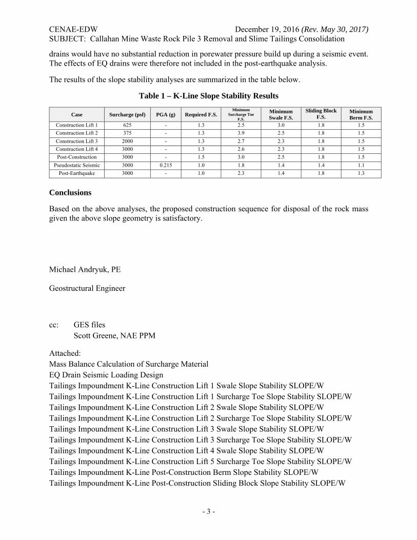
The results of the slope stability analyses are summarized in the table below.
Table 1 – K-Line Slope Stability Results
Case Surcharge (psf) PGA (g) Required F.S. Minimum
Surcharge Toe F.S.
Minimum Swale F.S.
Sliding Block F.S.
Minimum Berm F.S.
Construction Lift 1 625 - 1.3 2.5 3.0 1.8 1.5
Construction Lift 2 375 - 1.3 3.9 2.5 1.8 1.5
Construction Lift 3 2000 - 1.3 2.7 2.3 1.8 1.5
Construction Lift 4 3000 - 1.3 2.6 2.3 1.8 1.5
Post-Construction 3000 - 1.5 3.0 2.5 1.8 1.5
Pseudostatic Seismic 3000 0.215 1.0 1.8 1.4 1.4 1.1
Post-Earthquake 3000 - 1.0 2.3 1.4 1.8 1.3
Conclusions
Based on the above analyses, the proposed construction sequence for disposal of the rock mass given the above slope geometry is satisfactory.
Michael Andryuk, PE
Geostructural Engineer
cc: GES files Scott Greene, NAE PPM
Attached: Mass Balance Calculation of Surcharge Material EQ Drain Seismic Loading Design Tailings Impoundment K-Line Construction Lift 1 Swale Slope Stability SLOPE/W Tailings Impoundment K-Line Construction Lift 1 Surcharge Toe Slope Stability SLOPE/W Tailings Impoundment K-Line Construction Lift 2 Swale Slope Stability SLOPE/W Tailings Impoundment K-Line Construction Lift 2 Surcharge Toe Slope Stability SLOPE/W Tailings Impoundment K-Line Construction Lift 3 Swale Slope Stability SLOPE/W Tailings Impoundment K-Line Construction Lift 3 Surcharge Toe Slope Stability SLOPE/W Tailings Impoundment K-Line Construction Lift 4 Swale Slope Stability SLOPE/W Tailings Impoundment K-Line Construction Lift 5 Surcharge Toe Slope Stability SLOPE/W Tailings Impoundment K-Line Post-Construction Berm Slope Stability SLOPE/W Tailings Impoundment K-Line Post-Construction Sliding Block Slope Stability SLOPE/W
- 3 -
CENAE-EDW December 19, 2016 (Rev. May 30, 2017) SUBJECT: Callahan Mine Waste Rock Pile 3 Removal and Slime Tailings Consolidation
Tailings Impoundment K-Line Post-Construction Swale Slope Stability SLOPE/W Tailings Impoundment K-Line Post-Construction Surcharge Toe Slope Stability SLOPE/W Tailings Impoundment K-Line Pseudostatic Seismic Berm Slope Stability SLOPE/W Tailings Impoundment K-Line Pseudostatic Seismic Sliding Block Slope Stability SLOPE/W Tailings Impoundment K-Line Pseudostatic Seismic Swale Slope Stability SLOPE/W Tailings Impoundment K-Line Pseudostatic Seismic Surcharge Toe Slope Stability SLOPE/W Tailings Impoundment K-Line Post-Earthquake Berm Slope Stability SLOPE/W Tailings Impoundment K-Line Post-Earthquake Sliding Block Slope Stability SLOPE/W Tailings Impoundment K-Line Post-Earthquake Swale Slope Stability SLOPE/W Tailings Impoundment K-Line Post-Earthquake Surcharge Toe Slope Stability SLOPE/W
- 4 -
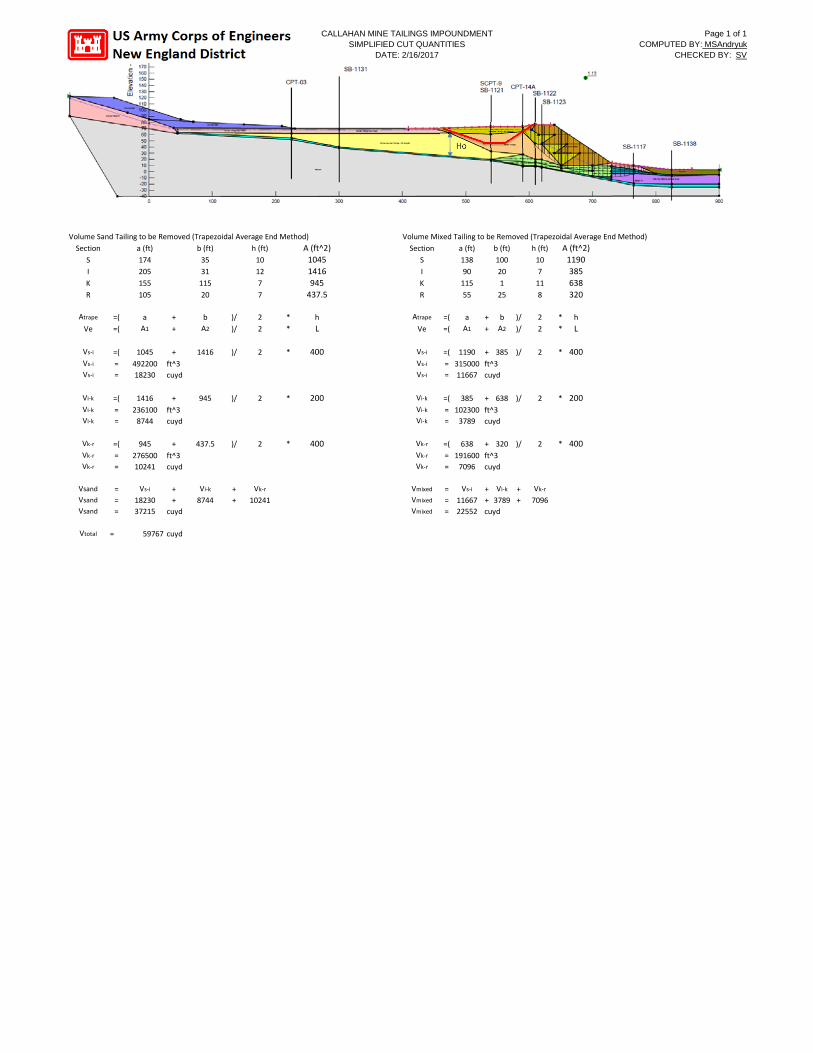
CALLAHAN MINE TAILINGS IMPOUNDMENT SIMPLIFIED CUT QUANTITIES
DATE: 2/16/2017
Page 1 of 1 COMPUTED BY: MSAndryuk
CHECKED BY: SV
Ho
Volume Sand Tailing to be Removed (Trapezoidal Average End Method) Volume Mixed Tailing to be Removed (Trapezoidal Average End Method)
Section a (ft) b (ft) h (ft) A (ft^2) Section a (ft) b (ft) h (ft) A (ft^2) S 174 35 10 1045 S 138 100 10 1190 I 205 31 12 1416 I 90 20 7 385 K 155 115 7 945 K 115 1 11 638 R 105 20 7 437.5 R 55 25 8 320
Atrape =( a + b )/ 2 * h Atrape =( a + b )/ 2 * h
Ve =( A1 + A2 )/ 2 * L Ve =( A1 + A2 )/ 2 * L
Vs‐i =( 1045 + 1416 )/ 2 * 400 Vs‐i =( 1190 + 385 )/ 2 * 400 Vs‐i = 492200 ft^3 Vs‐i = 315000 ft^3 Vs‐i = 18230 cuyd Vs‐i = 11667 cuyd
Vi‐k =( 1416 + 945 )/ 2 * 200 Vi‐k =( 385 + 638 )/ 2 * 200 Vi‐k = 236100 ft^3 Vi‐k = 102300 ft^3 Vi‐k = 8744 cuyd Vi‐k = 3789 cuyd
Vk‐r =( 945 + 437.5 )/ 2 * 400 Vk‐r =( 638 + 320 )/ 2 * 400 Vk‐r = 276500 ft^3 Vk‐r = 191600 ft^3 Vk‐r = 10241 cuyd Vk‐r = 7096 cuyd
Vsand = Vs‐i + Vi‐k + Vk‐r Vmixed = Vs‐i + Vi‐k + Vk‐r
Vsand = 18230 + 8744 + 10241 Vmixed = 11667 + 3789 + 7096 Vsand = 37215 cuyd Vmixed = 22552 cuyd
Vtotal = 59767 cuyd
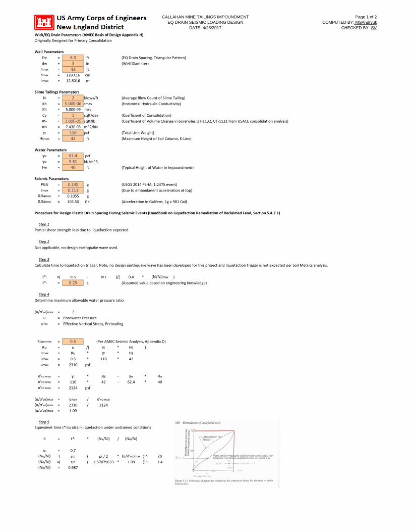
Wick/EQ Drain Parameters (AMEC Basis of Design Appendix H)
CALLAHAN MINE TAILINGS IMPOUNDMENT Page 1 of 2 EQ DRAIN SEISMIC LOADING DESIGN COMPUTED BY: MSAndryuk
DATE: 4/28/2017 CHECKED BY: SV
Originally Designed for Primary Consolidation
Slime Tailings Parameters
N = 2 Kh = 5.00E‐06 cm/s Kh = 5.00E‐09
Well Parameters
De = 6.3 3 42
ft (EQ Drain Spacing, Triangular Pattern)
dw = in (Well Diameter) hmax = ft hmax = 1280.16 cm hmax = 12.8016 m
blows/ft (Average Blow Count of Slime Tailing)
(Horizontal Hydraulic Conductivity) m/s
Cv = 1 sqft/day (Coefficient of Consolidation) mv = 1.80E‐05 sqft/lb (Coefficient of Volume Change in boreholes UT‐1132, UT‐1131 from USACE consolidation analysis) mv = 7.43E‐03 m^2/kN ɣt = 110
42 pcf (Total Unit Weight)
Hsmax = ft (Maximum Height of Soil Column, K‐Line)
Water Parameters ɣw = 62.4
9.81 40
pcf ɣw = kN/m^3 Hw = ft (Typical Height of Water in Impoundment)
Seismic Parameters
PGA = 0.145 0.211
g (USGS 2014 PSHA, 1:2475 event) amax = g (Due to embankment acceleration at top)
0.5amax = 0.1055 g 0.5amax = 103.50 Gal (Acceleration in Galileos, 1g = 981 Gal)
Procedure for Design Plastic Drain Spacing During Seismic Events (Handbook on Liquefaction Remediation of Reclaimed Land, Section 5.4.2.1)
Step 1 Partial shear strength loss due to liquefaction expected.
Step 2
Not applicable, no design earthquake wave used.
Step 3
Calculate time to liquefaction trigger. Note, no design earthquake wave has been developed for this project and liquefaction trigger is not expected per Soil Metrics analysis.
t*l =( t0.5 ‐ t0.1 )/( 0.4 * (N/Nl)max ) t*l = 0.25 s (Assumed value based on engineering knowledge)
Step 4
Determine maximum allowable water pressure ratio
(u/σ'vo)max = ?
u = Porewater Pressure σ'vo = Effective Vertical Stress, Preloading
Ruseismic = 0.5 (Per AMEC Sesimic Analysis, Appendix D)
Ru = u /( ɣt * Hs ) umax = Ru * ɣt * Hs umax = 0.5 * 110 * 42 umax = 2310 psf
σ'vo max = ɣt * Hs ‐ ɣw * Hw
σ'vo max = 110 * 42 ‐ 62.4 * 40 σ'vo max = 2124 psf
(u/σ'vo)max = umax / σ'vo max
(u/σ'vo)max = 2310 / 2124 (u/σ'vo)max = 1.09
Step 5 Equivalent time t*l to attain liquefaction under undrained conditions.
tl = t*l * (Nu/Nl) / (No/Nl)
α = 0.7 (No/Nl) =( sin ( pi / 2 * (u/σ'vo)max ))^ 2α (No/Nl) =( sin ( 1.57079633 * 1.09 ))^ 1.4 (No/Nl) = 0.987
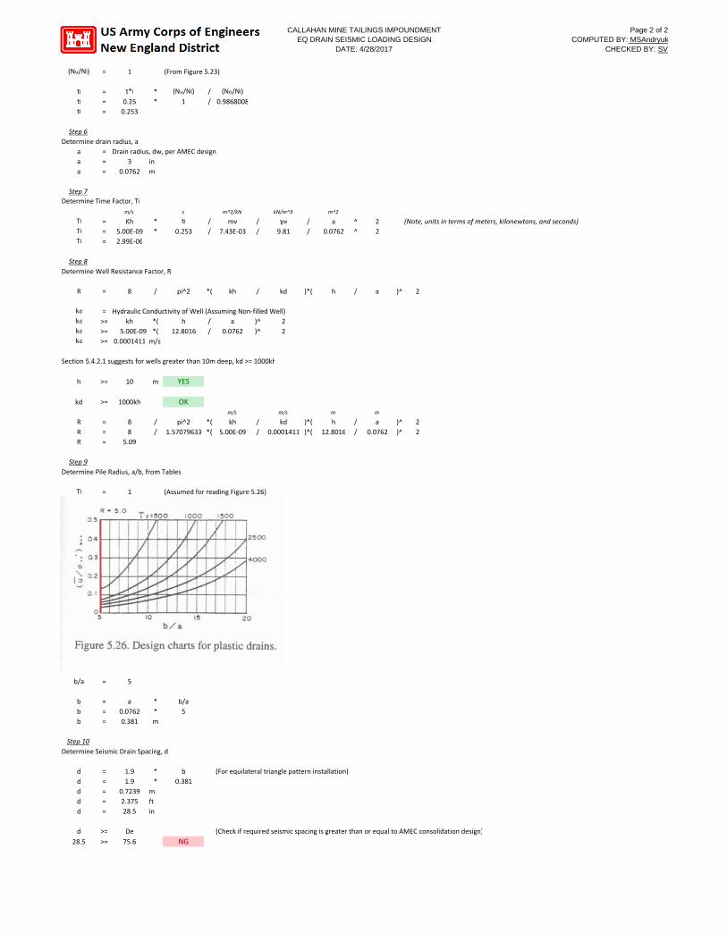
CALLAHAN MINE TAILINGS IMPOUNDMENT Page 2 of 2 EQ DRAIN SEISMIC LOADING DESIGN COMPUTED BY: MSAndryuk
DATE: 4/28/2017 CHECKED BY: SV
(Nu/Nl) = 1 (From Figure 5.23)
tl
tl
tl
= = =
t*l
0.25 0.253
* *
(Nu/Nl)
1 / /
(No/Nl)
0.9868008
Step 6 Determine drain radius, a
a = Drain radius, dw, per AMEC design a = 3 in a = 0.0762 m
Step 7 Determine Time Factor, Tl
m/s
Tl = Kh Tl = 5.00E‐09 Tl = 2.99E‐06
* *
s
tl
0.253 / /
m^2/kN
mv 7.43E‐03
/ /
kN/m^3
ɣw
9.81 / /
m^2
a 0.0762
^ ^
2 2
(Note, units in terms of meters, kilonewtons, and seconds)
Step 8 Determine Well Resistance Factor, R
R = 8 / pi^2 *( kh / kd )*( h / a )^ 2
kd
kd
kd
kd
= Hydraulic Conductivity of Well (Assuming Non‐filled Well) >= kh *( h / a )^ 2 >= 5.00E‐09 *( 12.8016 / 0.0762 )^ 2 >= 0.0001411 m/s
Section 5.4.2.1 suggests for wells greater than 10m deep, kd >= 1000kh
h >= 10 m YES
kd
R R R
>=
= = =
1000kh
8 8
5.09
/ /
OK
pi^2 *( 1.57079633 *(
m/s
kh 5.00E‐09
/ /
m/s
kd 0.0001411
)*( )*(
m
h 12.8016
/ /
m
a 0.0762
)^ )^
2 2
Step 9 Determine Pile Radius, a/b, from Tables
Tl = 1 (Assumed for reading Figure 5.26)
b/a = 5
b = a * b/a b = 0.0762 * 5 b = 0.381 m
Step 10 Determine Seismic Drain Spacing, d
d = 1.9 * b (For equilateral triangle pattern installation) d = 1.9 * 0.381 d = 0.7239 m d = 2.375 ft d = 28.5 in
d >= De (Check if required seismic spacing is greater than or equal to AMEC consolidation design)
28.5 >= 75.6 NG
Bedrock
Consolidated Clay*
Medium Stiff Clay*
Consolidated Clay*
Mixed Tailings*
Berm (rock waste)*
Sand-like Tailings*
Granular Material*
Soft Clay*
Alluvium*
Consolidated Clay*
Glacial Till*
Granular Material*
Ore Pad Mat'l*
Medium Stiff Clay*
Slimes Tailings
Slimes Tailings
Slimes Tailings
Ore Pad Mat'l*
Consolidated Clay*
Consolidated Clay*
Consolidated Clay*
Sand-like Tailings*
Glacial Till*
Consolidated Clay*
Consolidated Clay*
Medium Stiff Clay*
Sand-like Tailings*
Berm (rock waste)*
Sand-like Tailings*
Sand-like Tailings*
Slimes Tailings
2.5
Ele
vatio
n - f
eet
-40
10
60
110
160
210
260
310
360
Color Name Model Unit Weight (pcf)
Cohesion' (psf)
Phi' (°)
Phi-B (°)
Piezometric Line
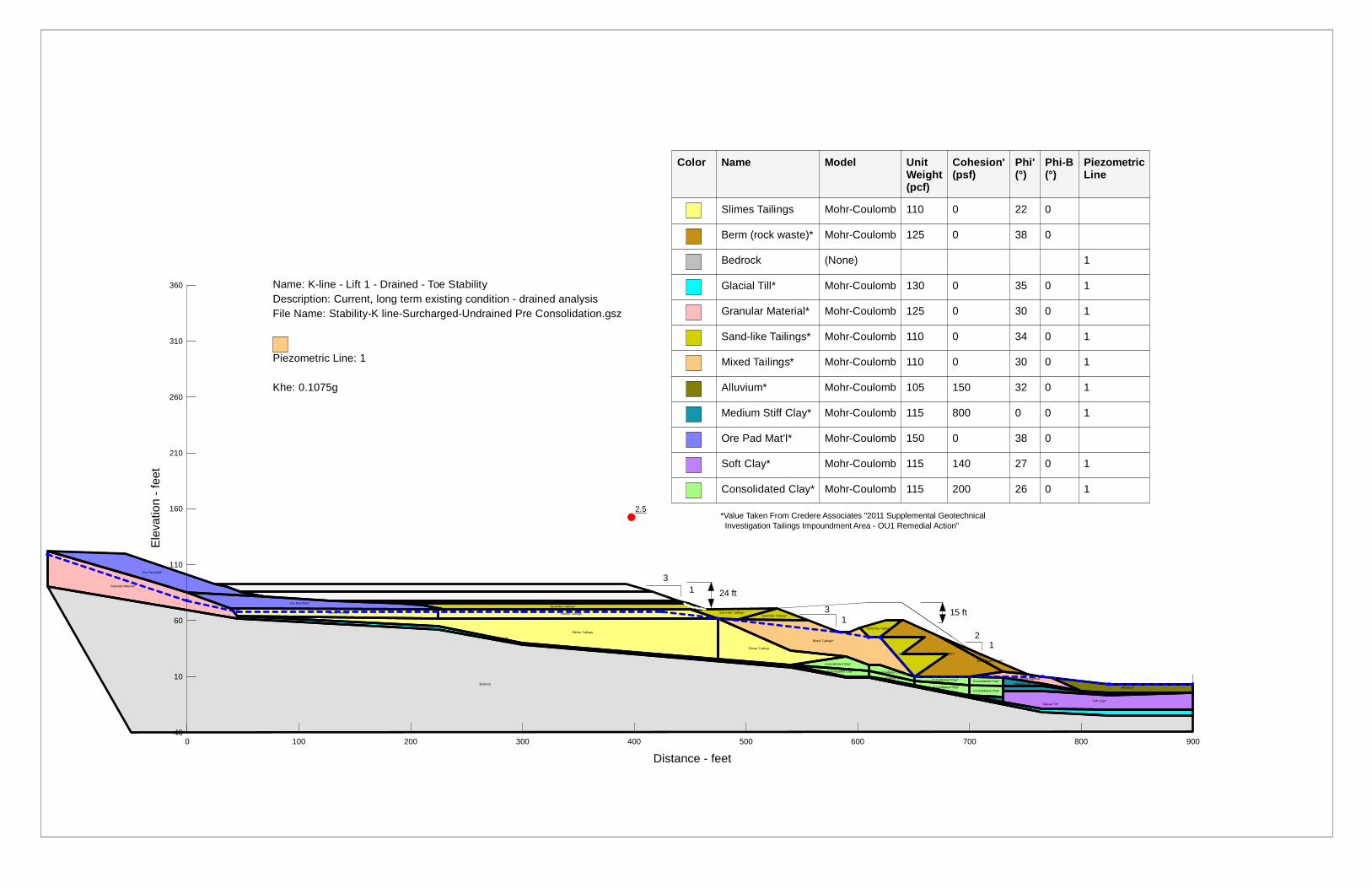
Slimes Tailings Mohr-Coulomb 110 0 22 0
Berm (rock waste)* Mohr-Coulomb 125 0 38 0
Bedrock (None) 1
Glacial Till* Mohr-Coulomb 130 0 35 0 1
Granular Material* Mohr-Coulomb 125 0 30 0 1
Sand-like Tailings* Mohr-Coulomb 110 0 34 0 1
Mixed Tailings* Mohr-Coulomb 110 0 30 0 1
Alluvium* Mohr-Coulomb 105 150 32 0 1
Medium Stiff Clay* Mohr-Coulomb 115 800 0 0 1
Ore Pad Mat'l* Mohr-Coulomb 150 0 38 0
Soft Clay* Mohr-Coulomb 115 140 27 0 1
Consolidated Clay* Mohr-Coulomb 115 200 26 0 1
3
3
1
1
1 2
Name: K-line - Lift 1 - Drained - Toe Stability Description: Current, long term existing condition - drained analysis File Name: Stability-K line-Surcharged-Undrained Pre Consolidation.gsz
Piezometric Line: 1
Khe: 0.1075g
15 ft
24 ft
*Value Taken From Credere Associates "2011 Supplemental Geotechnical Investigation Tailings Impoundment Area - OU1 Remedial Action"
0 100 200 300 400 500 600 700 800 900
Distance - feet
*
Bedrock
Consolidated Clay*
Medium Stiff Clay*
Consolidated Clay*
Mixed Tailings*
Berm (rock waste)*
Sand-like Tailings*
Granular Material*
Soft Clay*
Alluvium*
Consolidated Clay*
Glacial Till*
Granular Material*
Ore Pad Mat'l*
Medium Stiff Clay*
Slimes Tailings
Slimes Tailings
Slimes Tailings
Ore Pad Mat'l*
Consolidated Clay*
Consolidated Clay*
Consolidated Clay*
Sand-like Tailings*
Glacial Till*
Consolidated Clay*
Consolidated Clay*
Medium Stiff Clay*
Sand-like Tailings*
Berm (rock waste)*
Sand-like Tailings*
Sand-like Tailings*
Slimes Tailings
3.0
Ele
vatio
n - f
eet
-40
10
60
110
160
210
260
310
360
Color Name Model Unit Weight (pcf)
Cohesion' (psf)
Phi' (°)
Phi-B (°)
Piezometric Line
C-Top of Layer (psf)
C-Rate of Change ((lbs/ft²)/ft)
C-Maximum (psf)
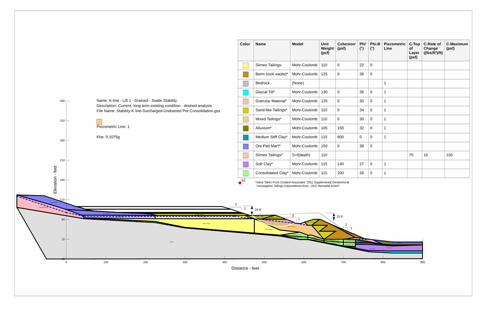
Slimes Tailings Mohr-Coulomb 110 0 22 0
Berm (rock waste)* Mohr-Coulomb 125 0 38 0
Bedrock (None) 1
Glacial Till* Mohr-Coulomb 130 0 35 0 1
Granular Material* Mohr-Coulomb 125 0 30 0 1
Sand-like Tailings* Mohr-Coulomb 110 0 34 0 1
Mixed Tailings* Mohr-Coulomb 110 0 30 0 1
Alluvium* Mohr-Coulomb 105 150 32 0 1
Medium Stiff Clay* Mohr-Coulomb 115 800 0 0 1
Ore Pad Mat'l* Mohr-Coulomb 150 0 38 0
Slimes Tailings* S=f(depth) 110 70 10 150
Soft Clay* Mohr-Coulomb 115 140 27 0 1
Consolidated Clay* Mohr-Coulomb 115 200 26 0 1
3
3
1
1
1 2
Name: K-line - Lift 1 - Drained - Swale Stability Description: Current, long term existing condition - drained analysis File Name: Stability-K line-Surcharged-Undrained Pre Consolidation.gsz
Piezometric Line: 1
Khe: 0.1075g
15 ft
24 ft
*Value Taken From Credere Associates "2011 Supplemental Geotechnical Investigation Tailings Impoundment Area - OU1 Remedial Action"
0 100 200 300 400 500 600 700 800 900
Distance - feet
2.5
Ele
vatio
n - f
eet
-40
10
60
110
160
210
260
310
360
Color Name Model Unit Weight (pcf)
Cohesion' (psf)
Phi' (°)
Phi-B (°)
Piezometric Line
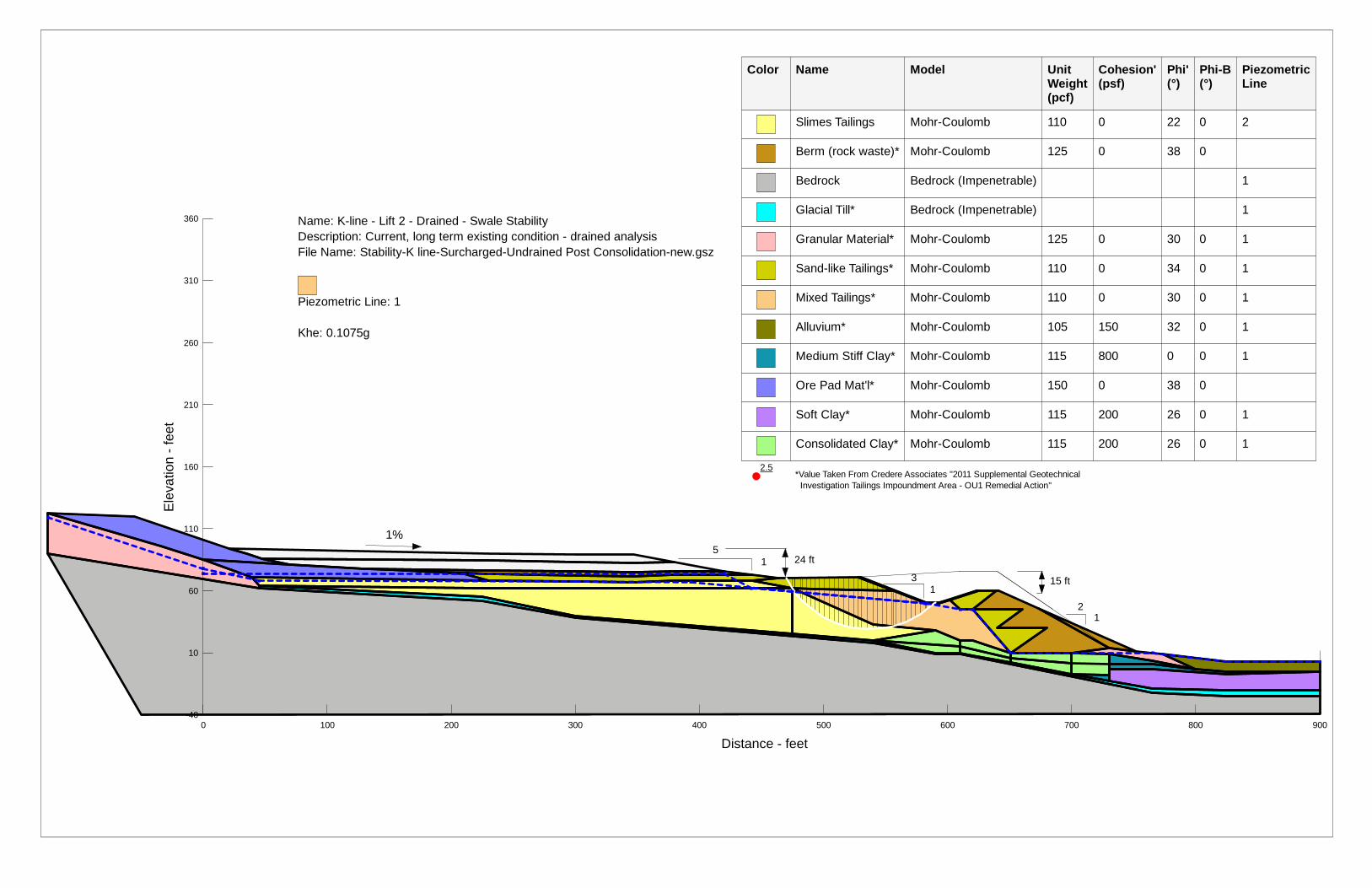
Slimes Tailings Mohr-Coulomb 110 0 22 0 2
Berm (rock waste)* Mohr-Coulomb 125 0 38 0
Bedrock Bedrock (Impenetrable) 1
Glacial Till* Bedrock (Impenetrable) 1
Granular Material* Mohr-Coulomb 125 0 30 0 1
Sand-like Tailings* Mohr-Coulomb 110 0 34 0 1
Mixed Tailings* Mohr-Coulomb 110 0 30 0 1
Alluvium* Mohr-Coulomb 105 150 32 0 1
Medium Stiff Clay* Mohr-Coulomb 115 800 0 0 1
Ore Pad Mat'l* Mohr-Coulomb 150 0 38 0
Soft Clay* Mohr-Coulomb 115 200 26 0 1
Consolidated Clay* Mohr-Coulomb 115 200 26 0 1
5
3 1
1
1 2
Name: K-line - Lift 2 - Drained - Swale Stability Description: Current, long term existing condition - drained analysis File Name: Stability-K line-Surcharged-Undrained Post Consolidation-new.gsz
Piezometric Line: 1
Khe: 0.1075g
15 ft
24 ft
*Value Taken From Credere Associates "2011 Supplemental Geotechnical Investigation Tailings Impoundment Area - OU1 Remedial Action"
1%
0 100 200 300 400 500 600 700 800 900
Distance - feet

3.9
Ele
vatio
n - f
eet
-40
10
60
110
160
210
260
310
360
Color Name Model Unit Weight (pcf)
Cohesion' (psf)
Phi' (°)
Phi-B (°)
Piezometric Line
Slimes Tailings Mohr-Coulomb 110 0 22 0 2
Berm (rock waste)* Mohr-Coulomb 125 0 38 0
Bedrock Bedrock (Impenetrable) 1
Glacial Till* Bedrock (Impenetrable) 1
Granular Material* Mohr-Coulomb 125 0 30 0 1
Sand-like Tailings* Mohr-Coulomb 110 0 34 0 1
Mixed Tailings* Mohr-Coulomb 110 0 30 0 1
Alluvium* Mohr-Coulomb 105 150 32 0 1
Medium Stiff Clay* Mohr-Coulomb 115 800 0 0 1
Ore Pad Mat'l* Mohr-Coulomb 150 0 38 0
Soft Clay* Mohr-Coulomb 115 200 26 0 1
Consolidated Clay* Mohr-Coulomb 115 200 26 0 1
5
3 1
1
1 2
Name: K-line - Lift 2 - Drained - Toe Stability Description: Current, long term existing condition - drained analysis File Name: Stability-K line-Surcharged-Undrained Post Consolidation-new.gsz
Piezometric Line: 1
Khe: 0.1075g
15 ft
24 ft
*Value Taken From Credere Associates "2011 Supplemental Geotechnical Investigation Tailings Impoundment Area - OU1 Remedial Action"
1%
0 100 200 300 400 500 600 700 800 900
Distance - feet
2.3
Ele
vatio
n - f
eet
-40
10
60
110
160
210
260
310
360
Color Name Model Unit Weight (pcf)
Cohesion' (psf)
Phi' (°)
Phi-B (°)
Piezometric Line
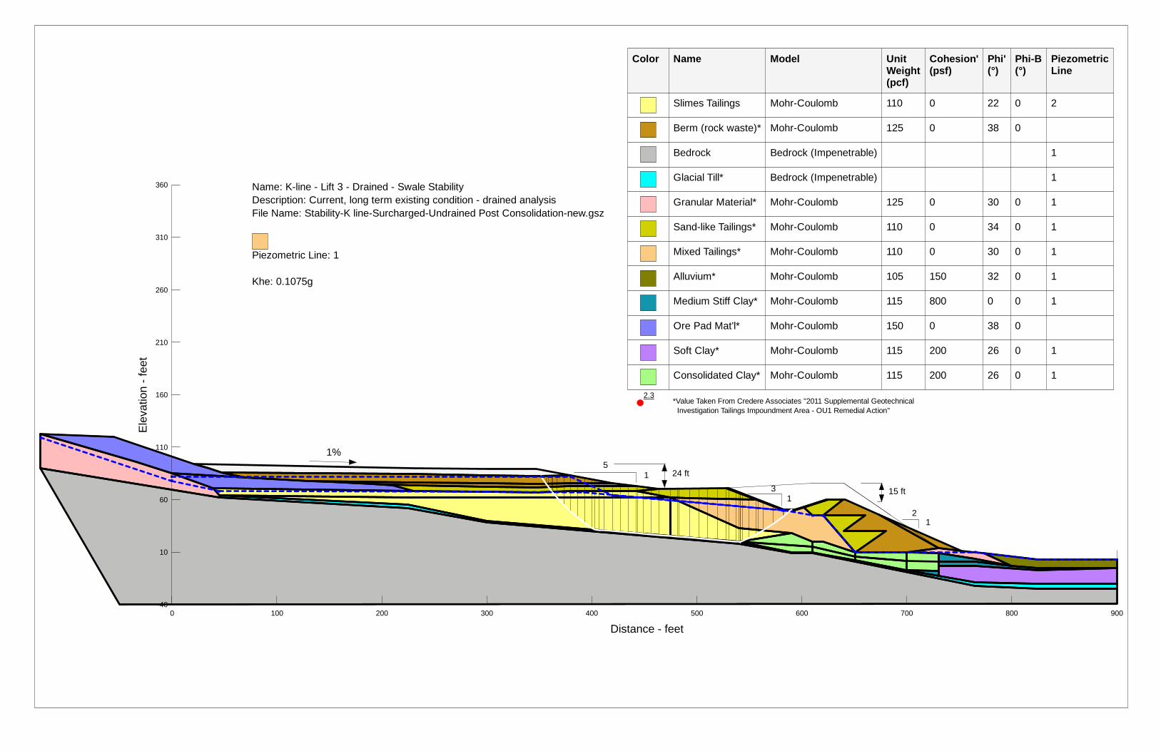
Slimes Tailings Mohr-Coulomb 110 0 22 0 2
Berm (rock waste)* Mohr-Coulomb 125 0 38 0
Bedrock Bedrock (Impenetrable) 1
Glacial Till* Bedrock (Impenetrable) 1
Granular Material* Mohr-Coulomb 125 0 30 0 1
Sand-like Tailings* Mohr-Coulomb 110 0 34 0 1
Mixed Tailings* Mohr-Coulomb 110 0 30 0 1
Alluvium* Mohr-Coulomb 105 150 32 0 1
Medium Stiff Clay* Mohr-Coulomb 115 800 0 0 1
Ore Pad Mat'l* Mohr-Coulomb 150 0 38 0
Soft Clay* Mohr-Coulomb 115 200 26 0 1
Consolidated Clay* Mohr-Coulomb 115 200 26 0 1
5
3 1
1
1 2
Name: K-line - Lift 3 - Drained - Swale Stability Description: Current, long term existing condition - drained analysis File Name: Stability-K line-Surcharged-Undrained Post Consolidation-new.gsz
Piezometric Line: 1
Khe: 0.1075g
15 ft
24 ft
*Value Taken From Credere Associates "2011 Supplemental Geotechnical Investigation Tailings Impoundment Area - OU1 Remedial Action"
1%
0 100 200 300 400 500 600 700 800 900
Distance - feet

2.7
Ele
vatio
n - f
eet
-40
10
60
110
160
210
260
310
360
Color Name Model Unit Weight (pcf)
Cohesion' (psf)
Phi' (°)
Phi-B (°)
Piezometric Line
Slimes Tailings Mohr-Coulomb 110 0 22 0 2
Berm (rock waste)* Mohr-Coulomb 125 0 38 0
Bedrock Bedrock (Impenetrable) 1
Glacial Till* Bedrock (Impenetrable) 1
Granular Material* Mohr-Coulomb 125 0 30 0 1
Sand-like Tailings* Mohr-Coulomb 110 0 34 0 1
Mixed Tailings* Mohr-Coulomb 110 0 30 0 1
Alluvium* Mohr-Coulomb 105 150 32 0 1
Medium Stiff Clay* Mohr-Coulomb 115 800 0 0 1
Ore Pad Mat'l* Mohr-Coulomb 150 0 38 0
Soft Clay* Mohr-Coulomb 115 200 26 0 1
Consolidated Clay* Mohr-Coulomb 115 200 26 0 1
5
3 1
1
1 2
Name: K-line - Lift 3 - Drained - Toe Stability Description: Current, long term existing condition - drained analysis File Name: Stability-K line-Surcharged-Undrained Post Consolidation-new.gsz
Piezometric Line: 1
Khe: 0.1075g
15 ft
24 ft
*Value Taken From Credere Associates "2011 Supplemental Geotechnical Investigation Tailings Impoundment Area - OU1 Remedial Action"
1%
0 100 200 300 400 500 600 700 800 900
Distance - feet
2.3
Ele
vatio
n - f
eet
-40
10
60
110
160
210
260
310
360
Color Name Model Unit Weight (pcf)
Cohesion' (psf)
Phi' (°)
Phi-B (°)
Piezometric Line
Slimes Tailings Mohr-Coulomb 110 0 22 0 2
Berm (rock waste)* Mohr-Coulomb 125 0 38 0
Bedrock Bedrock (Impenetrable) 1
Glacial Till* Bedrock (Impenetrable) 1
Granular Material* Mohr-Coulomb 125 0 30 0 1
Sand-like Tailings* Mohr-Coulomb 110 0 34 0 1
Mixed Tailings* Mohr-Coulomb 110 0 30 0 1
Alluvium* Mohr-Coulomb 105 150 32 0 1
Medium Stiff Clay* Mohr-Coulomb 115 800 0 0 1
Ore Pad Mat'l* Mohr-Coulomb 150 0 38 0
Soft Clay* Mohr-Coulomb 115 200 26 0 1
Consolidated Clay* Mohr-Coulomb 115 200 26 0 1
5
3 1
1
1 2
Name: K-line - Lift 4 - Drained - Swale Stability Description: Current, long term existing condition - drained analysis File Name: Stability-K line-Surcharged-Undrained Post Consolidation-new.gsz
Piezometric Line: 1
Khe: 0.1075g
15 ft
24 ft
*Value Taken From Credere Associates "2011 Supplemental Geotechnical Investigation Tailings Impoundment Area - OU1 Remedial Action"
1%
0 100 200 300 400 500 600 700 800 900
Distance - feet
2.6
Ele
vatio
n - f
eet
-40
10
60
110
160
210
260
310
360
Color Name Model Unit Weight (pcf)
Cohesion' (psf)
Phi' (°)
Phi-B (°)
Piezometric Line
Slimes Tailings Mohr-Coulomb 110 0 22 0 2
Berm (rock waste)* Mohr-Coulomb 125 0 38 0
Bedrock Bedrock (Impenetrable) 1
Glacial Till* Bedrock (Impenetrable) 1
Granular Material* Mohr-Coulomb 125 0 30 0 1
Sand-like Tailings* Mohr-Coulomb 110 0 34 0 1
Mixed Tailings* Mohr-Coulomb 110 0 30 0 1
Alluvium* Mohr-Coulomb 105 150 32 0 1
Medium Stiff Clay* Mohr-Coulomb 115 800 0 0 1
Ore Pad Mat'l* Mohr-Coulomb 150 0 38 0
Soft Clay* Mohr-Coulomb 115 200 26 0 1
Consolidated Clay* Mohr-Coulomb 115 200 26 0 1
5
3 1
1
1 2
Name: K-line - Lift 4 - Drained - Toe Stability Description: Current, long term existing condition - drained analysis File Name: Stability-K line-Surcharged-Undrained Post Consolidation-new.gsz
Piezometric Line: 1
Khe: 0.1075g
15 ft
24 ft
*Value Taken From Credere Associates "2011 Supplemental Geotechnical Investigation Tailings Impoundment Area - OU1 Remedial Action"
1%
0 100 200 300 400 500 600 700 800 900
Distance - feet

1.5
Ele
vatio
n - f
eet
-40
10
60
110
160
210
260
310
360
Color Name Model Unit Weight (pcf)
Cohesion' (psf)
Phi' (°)
Phi-B (°)
Piezometric Line
Slimes Tailings Mohr-Coulomb 110 0 22 0 1
Berm (rock waste)* Mohr-Coulomb 125 0 38 0
Bedrock Bedrock (Impenetrable) 1
Glacial Till* Bedrock (Impenetrable) 1
Granular Material* Mohr-Coulomb 125 0 30 0 1
Sand-like Tailings* Mohr-Coulomb 110 0 34 0 1
Mixed Tailings* Mohr-Coulomb 110 0 30 0 1
Alluvium* Mohr-Coulomb 105 150 32 0 1
Medium Stiff Clay* Mohr-Coulomb 115 800 0 0 1
Ore Pad Mat'l* Mohr-Coulomb 150 0 38 0
Soft Clay* Mohr-Coulomb 115 200 26 0 1
Consolidated Clay* Mohr-Coulomb 115 200 26 0 1
5
3 1
1
1 2
Name: K-line - Long Term Post-Construction - Berm Stability Description: Current, long term existing condition - drained analysis File Name: Stability-K line-Surcharged-Undrained Post Consolidation-Cap.gsz
Piezometric Line: 1
15 ft
24 ft
*Value Taken From Credere Associates "2011 Supplemental Geotechnical Investigation Tailings Impoundment Area - OU1 Remedial Action"
1% Landfill Cap
0 100 200 300 400 500 600 700 800 900
Distance - feet
1.8
Ele
vatio
n - f
eet
-40
10
60
110
160
210
260
310
360
Color Name Model Unit Weight (pcf)
Cohesion' (psf)
Phi' (°)
Phi-B (°)
Piezometric Line
Slimes Tailings Mohr-Coulomb 110 0 22 0 1
Berm (rock waste)* Mohr-Coulomb 125 0 38 0
Bedrock Bedrock (Impenetrable) 1
Glacial Till* Bedrock (Impenetrable) 1
Granular Material* Mohr-Coulomb 125 0 30 0 1
Sand-like Tailings* Mohr-Coulomb 110 0 34 0 1
Mixed Tailings* Mohr-Coulomb 110 0 30 0 1
Alluvium* Mohr-Coulomb 105 150 32 0 1
Ore Pad Mat'l* Mohr-Coulomb 150 0 38 0
Clay Sliding Surface Bedrock (Impenetrable) 1
5
3 1
1
1 2
Name: K-line - Long Term Post-Construction - Sliding Block Description: Current, long term existing condition - drained analysis File Name: Stability-K line-Surcharged-Undrained Post Consolidation-Cap.gsz
Piezometric Line: 1
15 ft
24 ft
*Value Taken From Credere Associates "2011 Supplemental Geotechnical Investigation Tailings Impoundment Area - OU1 Remedial Action"
1% Landfill Cap
0 100 200 300 400 500 600 700 800 900
Distance - feet

2.5
Ele
vatio
n - f
eet
-40
10
60
110
160
210
260
310
360
Color Name Model Unit Weight (pcf)
Cohesion' (psf)
Phi' (°)
Phi-B (°)
Piezometric Line
Slimes Tailings Mohr-Coulomb 110 0 22 0 1
Berm (rock waste)* Mohr-Coulomb 125 0 38 0
Bedrock Bedrock (Impenetrable) 1
Glacial Till* Bedrock (Impenetrable) 1
Granular Material* Mohr-Coulomb 125 0 30 0 1
Sand-like Tailings* Mohr-Coulomb 110 0 34 0 1
Mixed Tailings* Mohr-Coulomb 110 0 30 0 1
Alluvium* Mohr-Coulomb 105 150 32 0 1
Medium Stiff Clay* Mohr-Coulomb 115 800 0 0 1
Ore Pad Mat'l* Mohr-Coulomb 150 0 38 0
Soft Clay* Mohr-Coulomb 115 200 26 0 1
Consolidated Clay* Mohr-Coulomb 115 200 26 0 1
5
3 1
1
1 2
Name: K-line - Long Term Post-Construction - Swale Stability Description: Current, long term existing condition - drained analysis File Name: Stability-K line-Surcharged-Undrained Post Consolidation-Cap.gsz
Piezometric Line: 1
15 ft
24 ft
*Value Taken From Credere Associates "2011 Supplemental Geotechnical Investigation Tailings Impoundment Area - OU1 Remedial Action"
1% Landfill Cap
0 100 200 300 400 500 600 700 800 900
Distance - feet
3.0
Ele
vatio
n - f
eet
-40
10
60
110
160
210
260
310
360
Color Name Model Unit Weight (pcf)
Cohesion' (psf)
Phi' (°)
Phi-B (°)
Piezometric Line
Slimes Tailings Mohr-Coulomb 110 0 22 0 1
Berm (rock waste)* Mohr-Coulomb 125 0 38 0
Bedrock Bedrock (Impenetrable) 1
Glacial Till* Bedrock (Impenetrable) 1
Granular Material* Mohr-Coulomb 125 0 30 0 1
Sand-like Tailings* Mohr-Coulomb 110 0 34 0 1
Mixed Tailings* Mohr-Coulomb 110 0 30 0 1
Alluvium* Mohr-Coulomb 105 150 32 0 1
Medium Stiff Clay* Mohr-Coulomb 115 800 0 0 1
Ore Pad Mat'l* Mohr-Coulomb 150 0 38 0
Soft Clay* Mohr-Coulomb 115 200 26 0 1
Consolidated Clay* Mohr-Coulomb 115 200 26 0 1
5
3 1
1
1 2
Name: K-line - Long Term Post-Construction - Toe Stability Description: Current, long term existing condition - drained analysis File Name: Stability-K line-Surcharged-Undrained Post Consolidation-Cap.gsz
Piezometric Line: 1
15 ft
24 ft
*Value Taken From Credere Associates "2011 Supplemental Geotechnical Investigation Tailings Impoundment Area - OU1 Remedial Action"
1% Landfill Cap
0 100 200 300 400 500 600 700 800 900
Distance - feet
1.8
Ele
vatio
n - f
eet
-40
10
60
110
160
210
260
310
360
Color Name Model Unit Weight(pcf)
Cohesion' (psf)
Phi' (°)
Phi-B (°)
Piezometric Line
Slimes Tailings Mohr-Coulomb 110 0 22 0 1
Berm (rock waste)* Mohr-Coulomb 125 0 38 0
Bedrock Bedrock (Impenetrable) 1
Glacial Till* Bedrock (Impenetrable) 1
Granular Material* Mohr-Coulomb 125 0 30 0 1
Sand-like Tailings* Mohr-Coulomb 110 0 34 0 1
Mixed Tailings* Mohr-Coulomb 110 0 30 0 1
Alluvium* Mohr-Coulomb 105 150 32 0 1
Medium Stiff Clay* Mohr-Coulomb 115 800 0 0 1
Ore Pad Mat'l* Mohr-Coulomb 150 0 38 0
Soft Clay* Mohr-Coulomb 115 200 26 0 1
Consolidated Clay* Mohr-Coulomb 115 200 26 0 1
5
3 1
1
1 2
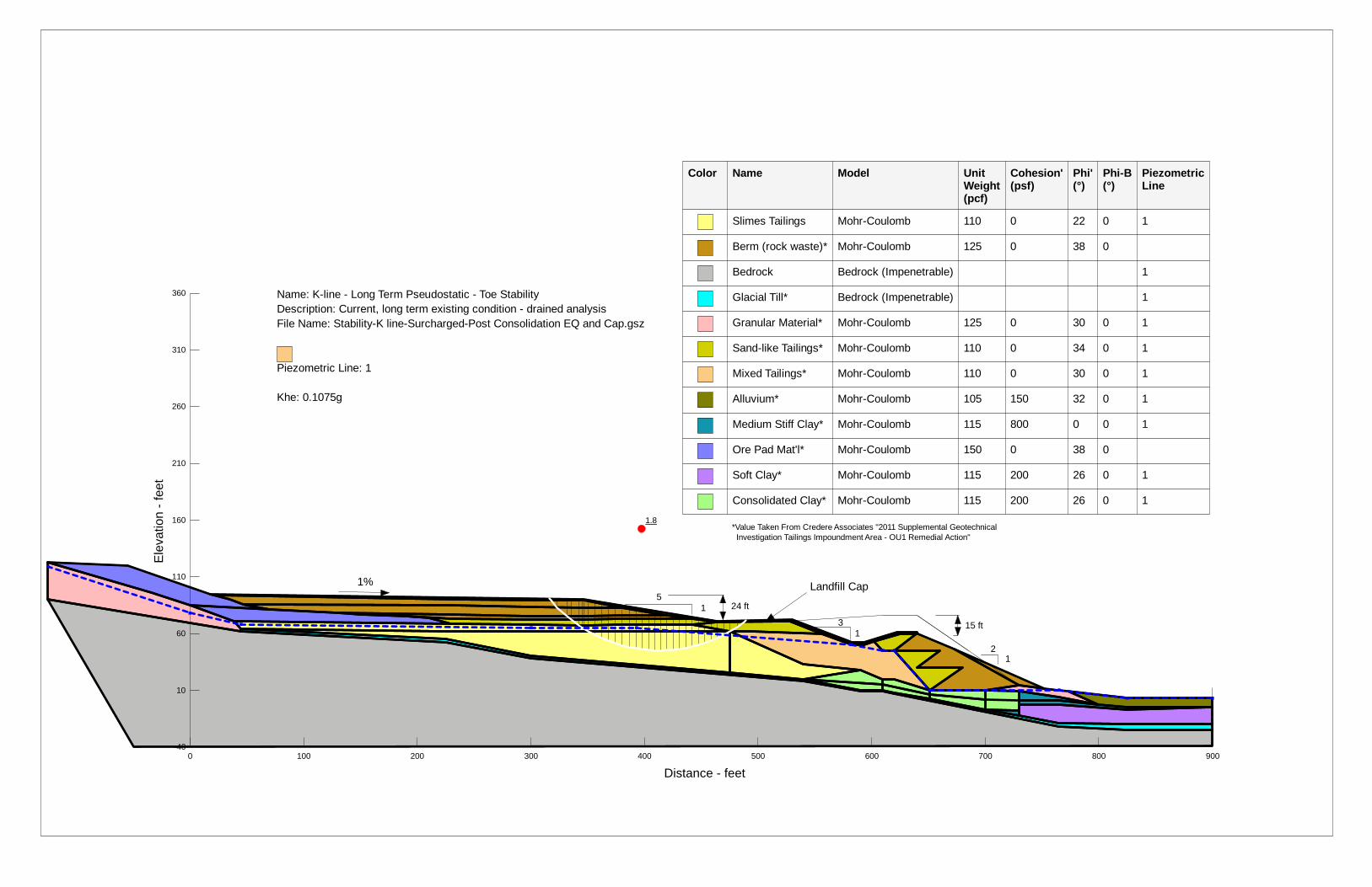
Name: K-line - Long Term Pseudostatic - Toe Stability Description: Current, long term existing condition - drained analysis File Name: Stability-K line-Surcharged-Post Consolidation EQ and Cap.gsz
Piezometric Line: 1
Khe: 0.1075g
15 ft
24 ft
*Value Taken From Credere Associates "2011 Supplemental Geotechnical Investigation Tailings Impoundment Area - OU1 Remedial Action"
1% Landfill Cap
0 100 200 300 400 500 600 700 800 900
Distance - feet

1.1
Ele
vatio
n - f
eet
-40
10
60
110
160
210
260
310
360
Color Name Model Unit Weight(pcf)
Cohesion' (psf)
Phi' (°)
Phi-B (°)
Piezometric Line
Slimes Tailings Mohr-Coulomb 110 0 22 0 1
Berm (rock waste)* Mohr-Coulomb 125 0 38 0
Bedrock Bedrock (Impenetrable) 1
Glacial Till* Bedrock (Impenetrable) 1
Granular Material* Mohr-Coulomb 125 0 30 0 1
Sand-like Tailings* Mohr-Coulomb 110 0 34 0 1
Mixed Tailings* Mohr-Coulomb 110 0 30 0 1
Alluvium* Mohr-Coulomb 105 150 32 0 1
Medium Stiff Clay* Mohr-Coulomb 115 800 0 0 1
Ore Pad Mat'l* Mohr-Coulomb 150 0 38 0
Soft Clay* Mohr-Coulomb 115 200 26 0 1
Consolidated Clay* Mohr-Coulomb 115 200 26 0 1
5
3 1
1
1 2
Name: K-line - Long Term Pseudostatic - Berm Stability Description: Current, long term existing condition - drained analysis File Name: Stability-K line-Surcharged-Post Consolidation EQ and Cap.gsz
Piezometric Line: 1
Khe: 0.1075g
15 ft
24 ft
*Value Taken From Credere Associates "2011 Supplemental Geotechnical Investigation Tailings Impoundment Area - OU1 Remedial Action"
1% Landfill Cap
0 100 200 300 400 500 600 700 800 900
Distance - feet

1.4
Ele
vatio
n - f
eet
-40
10
60
110
160
210
260
310
360
Color Name Model Unit Weight(pcf)
Cohesion' (psf)
Phi' (°)
Phi-B (°)
Piezometric Line
Slimes Tailings Mohr-Coulomb 110 0 22 0 1
Berm (rock waste)* Mohr-Coulomb 125 0 38 0
Bedrock Bedrock (Impenetrable) 1
Glacial Till* Bedrock (Impenetrable) 1
Granular Material* Mohr-Coulomb 125 0 30 0 1
Sand-like Tailings* Mohr-Coulomb 110 0 34 0 1
Mixed Tailings* Mohr-Coulomb 110 0 30 0 1
Alluvium* Mohr-Coulomb 105 150 32 0 1
Ore Pad Mat'l* Mohr-Coulomb 150 0 38 0
Clay Sliding Surface Bedrock (Impenetrable) 1
5
3 1
1
1 2
Name: K-line - Long Term Pseudostatic - Sliding Block Description: Current, long term existing condition - drained analysis File Name: Stability-K line-Surcharged-Post Consolidation EQ and Cap.gsz
Piezometric Line: 1
Khe: 0.1075g
15 ft
24 ft
*Value Taken From Credere Associates "2011 Supplemental Geotechnical Investigation Tailings Impoundment Area - OU1 Remedial Action"
1% Landfill Cap
0 100 200 300 400 500 600 700 800 900
Distance - feet

1.4
Ele
vatio
n - f
eet
-40
10
60
110
160
210
260
310
360
Color Name Model Unit Weight(pcf)
Cohesion' (psf)
Phi' (°)
Phi-B (°)
Piezometric Line
Slimes Tailings Mohr-Coulomb 110 0 22 0 1
Berm (rock waste)* Mohr-Coulomb 125 0 38 0
Bedrock Bedrock (Impenetrable) 1
Glacial Till* Bedrock (Impenetrable) 1
Granular Material* Mohr-Coulomb 125 0 30 0 1
Sand-like Tailings* Mohr-Coulomb 110 0 34 0 1
Mixed Tailings* Mohr-Coulomb 110 0 30 0 1
Alluvium* Mohr-Coulomb 105 150 32 0 1
Medium Stiff Clay* Mohr-Coulomb 115 800 0 0 1
Ore Pad Mat'l* Mohr-Coulomb 150 0 38 0
Soft Clay* Mohr-Coulomb 115 200 26 0 1
Consolidated Clay* Mohr-Coulomb 115 200 26 0 1
5
3 1
1
1 2
Name: K-line - Long Term Pseudostatic - Swale Stability Description: Current, long term existing condition - drained analysis File Name: Stability-K line-Surcharged-Post Consolidation EQ and Cap.gsz
Piezometric Line: 1
Khe: 0.1075g
15 ft
24 ft
*Value Taken From Credere Associates "2011 Supplemental Geotechnical Investigation Tailings Impoundment Area - OU1 Remedial Action"
1% Landfill Cap
0 100 200 300 400 500 600 700 800 900
Distance - feet
2.3
Ele
vatio
n - f
eet
-40
10
60
110
160
210
260
310
360
5
3 1
1
1 2
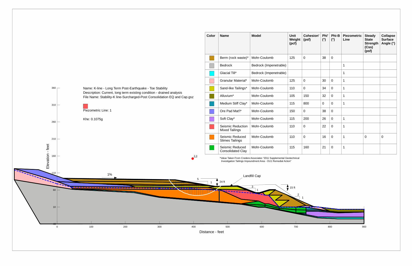
Name: K-line - Long Term Post-Earthquake - Toe Stability Description: Current, long term existing condition - drained analysis File Name: Stability-K line-Surcharged-Post Consolidation EQ and Cap.gsz
Piezometric Line: 1
Khe: 0.1075g
15 ft
24 ft
*Value Taken From Credere Associates "2011 Supplemental Geotechnical Investigation Tailings Impoundment Area - OU1 Remedial Action"
1% Landfill Cap
Color Name Model Unit Weight(pcf)
Cohesion' (psf)
Phi' (°)
Phi-B (°)
Piezometric Line
Steady State Strength (Css)(psf)
Collapse Surface Angle (°)
Berm (rock waste)* Mohr-Coulomb 125 0 38 0
Bedrock Bedrock (Impenetrable) 1
Glacial Till* Bedrock (Impenetrable) 1
Granular Material* Mohr-Coulomb 125 0 30 0 1
Sand-like Tailings* Mohr-Coulomb 110 0 34 0 1
Alluvium* Mohr-Coulomb 105 150 32 0 1
Medium Stiff Clay* Mohr-Coulomb 115 800 0 0 1
Ore Pad Mat'l* Mohr-Coulomb 150 0 38 0
Soft Clay* Mohr-Coulomb 115 200 26 0 1
Seismic Reduction Mixed Tailings
Mohr-Coulomb 110 0 22 0 1
Seismic Reduced Slimes Tailings
Mohr-Coulomb 110 0 16 0 1 0 0
Seismic Reduced Consolidated Clay
Mohr-Coulomb 115 160 21 0 1
0 100 200 300 400 500 600 700 800 900
Distance - feet

1.3
Ele
vatio
n - f
eet
-40
10
60
110
160
210
260
310
360
5
3 1
1
1 2
Name: K-line - Long Term Post-Earthquake - Berm Stability Description: Current, long term existing condition - drained analysis File Name: Stability-K line-Surcharged-Post Consolidation EQ and Cap.gsz
Piezometric Line: 1
Khe: 0.1075g
15 ft
24 ft
*Value Taken From Credere Associates "2011 Supplemental Geotechnical Investigation Tailings Impoundment Area - OU1 Remedial Action"
1% Landfill Cap
Color Name Model Unit Weight(pcf)
Cohesion' (psf)
Phi' (°)
Phi-B (°)
Piezometric Line
Steady State Strength (Css)(psf)
Collapse Surface Angle (°)
Berm (rock waste)* Mohr-Coulomb 125 0 38 0
Bedrock Bedrock (Impenetrable) 1
Glacial Till* Bedrock (Impenetrable) 1
Granular Material* Mohr-Coulomb 125 0 30 0 1
Sand-like Tailings* Mohr-Coulomb 110 0 34 0 1
Alluvium* Mohr-Coulomb 105 150 32 0 1
Medium Stiff Clay* Mohr-Coulomb 115 800 0 0 1
Ore Pad Mat'l* Mohr-Coulomb 150 0 38 0
Soft Clay* Mohr-Coulomb 115 200 26 0 1
Seismic Reduction Mixed Tailings
Mohr-Coulomb 110 0 22 0 1
Seismic Reduced Slimes Tailings
Mohr-Coulomb 110 0 16 0 1 0 0
Seismic Reduced Consolidated Clay
Mohr-Coulomb 115 160 21 0 1
0 100 200 300 400 500 600 700 800 900
Distance - feet

1.8
Ele
vatio
n - f
eet
-40
10
60
110
160
210
260
310
360
5
3 1
1
1 2
Name: K-line - Long Term Post-Earthquake - Sliding Block Description: Current, long term existing condition - drained analysis File Name: Stability-K line-Surcharged-Post Consolidation EQ and Cap.gsz
Piezometric Line: 1
Khe: 0.1075g
15 ft
24 ft
*Value Taken From Credere Associates "2011 Supplemental Geotechnical Investigation Tailings Impoundment Area - OU1 Remedial Action"
1% Landfill Cap
Color Name Model Unit Weight(pcf)
Cohesion' (psf)
Phi' (°)
Phi-B (°)
Piezometric Line
Steady State Strength (Css)(psf)
Collapse Surface Angle (°)
Berm (rock waste)* Mohr-Coulomb 125 0 38 0
Bedrock Bedrock (Impenetrable) 1
Glacial Till* Bedrock (Impenetrable) 1
Granular Material* Mohr-Coulomb 125 0 30 0 1
Sand-like Tailings* Mohr-Coulomb 110 0 34 0 1
Alluvium* Mohr-Coulomb 105 150 32 0 1
Ore Pad Mat'l* Mohr-Coulomb 150 0 38 0
Seismic Reduction Mixed Tailings
Mohr-Coulomb 110 0 22 0 1
Seismic Reduced Slimes Tailings
Mohr-Coulomb 110 0 16 0 1 0 0
Clay Sliding Surface
Bedrock (Impenetrable) 1
0 100 200 300 400 500 600 700 800 900
Distance - feet

1.4
Ele
vatio
n - f
eet
-40
10
60
110
160
210
260
310
360
5
3 1
1
1 2
Name: K-line - Long Term Post-Earthquake - Swale Stability Description: Current, long term existing condition - drained analysis File Name: Stability-K line-Surcharged-Post Consolidation EQ and Cap.gsz
Piezometric Line: 1
Khe: 0.1075g
15 ft
24 ft
*Value Taken From Credere Associates "2011 Supplemental Geotechnical Investigation Tailings Impoundment Area - OU1 Remedial Action"
1% Landfill Cap
Color Name Model Unit Weight(pcf)
Cohesion' (psf)
Phi' (°)
Phi-B (°)
Piezometric Line
Steady State Strength (Css)(psf)
Collapse Surface Angle (°)
Berm (rock waste)* Mohr-Coulomb 125 0 38 0
Bedrock Bedrock (Impenetrable) 1
Glacial Till* Bedrock (Impenetrable) 1
Granular Material* Mohr-Coulomb 125 0 30 0 1
Sand-like Tailings* Mohr-Coulomb 110 0 34 0 1
Alluvium* Mohr-Coulomb 105 150 32 0 1
Medium Stiff Clay* Mohr-Coulomb 115 800 0 0 1
Ore Pad Mat'l* Mohr-Coulomb 150 0 38 0
Soft Clay* Mohr-Coulomb 115 200 26 0 1
Seismic Reduction Mixed Tailings
Mohr-Coulomb 110 0 22 0 1
Seismic Reduced Slimes Tailings
Mohr-Coulomb 110 0 16 0 1 0 0
Seismic Reduced Consolidated Clay
Mohr-Coulomb 115 160 21 0 1
0 100 200 300 400 500 600 700 800 900
Distance - feet
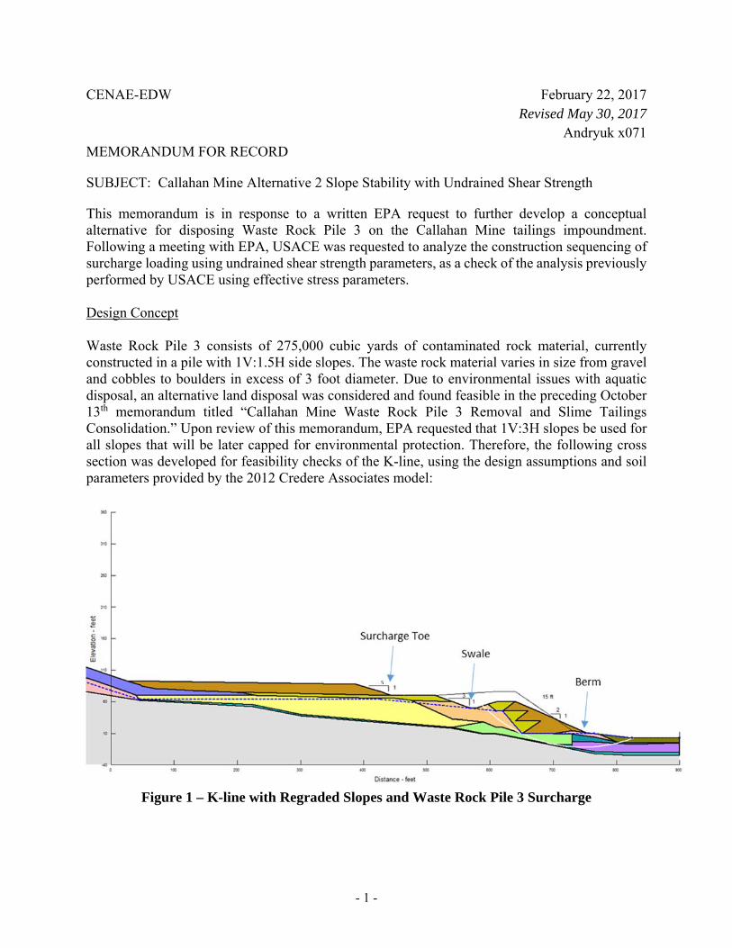
CENAE-EDW February 22, 2017 Revised May 30, 2017
Andryuk x071 MEMORANDUM FOR RECORD
SUBJECT: Callahan Mine Alternative 2 Slope Stability with Undrained Shear Strength
This memorandum is in response to a written EPA request to further develop a conceptual alternative for disposing Waste Rock Pile 3 on the Callahan Mine tailings impoundment. Following a meeting with EPA, USACE was requested to analyze the construction sequencing of surcharge loading using undrained shear strength parameters, as a check of the analysis previously performed by USACE using effective stress parameters.
Design Concept
Waste Rock Pile 3 consists of 275,000 cubic yards of contaminated rock material, currently constructed in a pile with 1V:1.5H side slopes. The waste rock material varies in size from gravel and cobbles to boulders in excess of 3 foot diameter. Due to environmental issues with aquatic disposal, an alternative land disposal was considered and found feasible in the preceding October 13th memorandum titled “Callahan Mine Waste Rock Pile 3 Removal and Slime Tailings Consolidation.” Upon review of this memorandum, EPA requested that 1V:3H slopes be used for all slopes that will be later capped for environmental protection. Therefore, the following cross section was developed for feasibility checks of the K-line, using the design assumptions and soil parameters provided by the 2012 Credere Associates model:
5
Figure 1 – K-line with Regraded Slopes and Waste Rock Pile 3 Surcharge
- 1 -
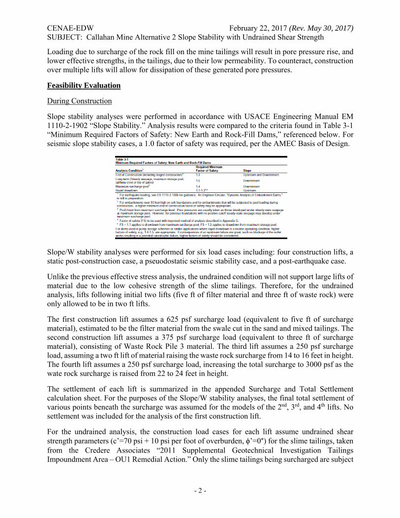
CENAE-EDW February 22, 2017 (Rev. May 30, 2017) SUBJECT: Callahan Mine Alternative 2 Slope Stability with Undrained Shear Strength
Loading due to surcharge of the rock fill on the mine tailings will result in pore pressure rise, and lower effective strengths, in the tailings, due to their low permeability. To counteract, construction over multiple lifts will allow for dissipation of these generated pore pressures.
Feasibility Evaluation
During Construction
Slope stability analyses were performed in accordance with USACE Engineering Manual EM 1110-2-1902 “Slope Stability.” Analysis results were compared to the criteria found in Table 3-1 “Minimum Required Factors of Safety: New Earth and Rock-Fill Dams,” referenced below. For seismic slope stability cases, a 1.0 factor of safety was required, per the AMEC Basis of Design.
Slope/W stability analyses were performed for six load cases including: four construction lifts, a static post-construction case, a pseuodostatic seismic stability case, and a post-earthquake case.
Unlike the previous effective stress analysis, the undrained condition will not support large lifts of material due to the low cohesive strength of the slime tailings. Therefore, for the undrained analysis, lifts following initial two lifts (five ft of filter material and three ft of waste rock) were only allowed to be in two ft lifts.
The first construction lift assumes a 625 psf surcharge load (equivalent to five ft of surcharge material), estimated to be the filter material from the swale cut in the sand and mixed tailings. The second construction lift assumes a 375 psf surcharge load (equivalent to three ft of surcharge material), consisting of Waste Rock Pile 3 material. The third lift assumes a 250 psf surcharge load, assuming a two ft lift of material raising the waste rock surcharge from 14 to 16 feet in height. The fourth lift assumes a 250 psf surcharge load, increasing the total surcharge to 3000 psf as the wate rock surcharge is raised from 22 to 24 feet in height.
The settlement of each lift is summarized in the appended Surcharge and Total Settlement calculation sheet. For the purposes of the Slope/W stability analyses, the final total settlement of various points beneath the surcharge was assumed for the models of the 2nd, 3rd, and 4th lifts. No settlement was included for the analysis of the first construction lift.
For the undrained analysis, the construction load cases for each lift assume undrained shear strength parameters (c’=70 psi + 10 psi per foot of overburden, ϕ’=0°) for the slime tailings, taken from the Credere Associates “2011 Supplemental Geotechnical Investigation Tailings Impoundment Area – OU1 Remedial Action.” Only the slime tailings being surcharged are subject
- 2 -
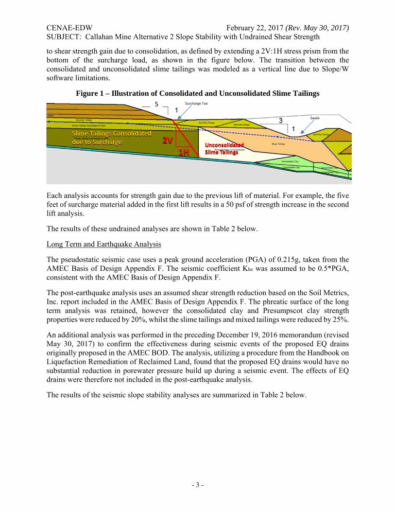
CENAE-EDW February 22, 2017 (Rev. May 30, 2017) SUBJECT: Callahan Mine Alternative 2 Slope Stability with Undrained Shear Strength
to shear strength gain due to consolidation, as defined by extending a 2V:1H stress prism from the bottom of the surcharge load, as shown in the figure below. The transition between the consolidated and unconsolidated slime tailings was modeled as a vertical line due to Slope/W software limitations.
Figure 1 – Illustration of Consolidated and Unconsolidated Slime Tailings Surcharge Toe
Swale
5
Each analysis accounts for strength gain due to the previous lift of material. For example, the five feet of surcharge material added in the first lift results in a 50 psf of strength increase in the second lift analysis.
The results of these undrained analyses are shown in Table 2 below.
Long Term and Earthquake Analysis
The pseudostatic seismic case uses a peak ground acceleration (PGA) of 0.215g, taken from the AMEC Basis of Design Appendix F. The seismic coefficient Khe was assumed to be 0.5*PGA, consistent with the AMEC Basis of Design Appendix F.
The post-earthquake analysis uses an assumed shear strength reduction based on the Soil Metrics, Inc. report included in the AMEC Basis of Design Appendix F. The phreatic surface of the long term analysis was retained, however the consolidated clay and Presumpscot clay strength properties were reduced by 20%, whilst the slime tailings and mixed tailings were reduced by 25%.
An additional analysis was performed in the preceding December 19, 2016 memorandum (revised May 30, 2017) to confirm the effectiveness during seismic events of the proposed EQ drains originally proposed in the AMEC BOD. The analysis, utilizing a procedure from the Handbook on Liquefaction Remediation of Reclaimed Land, found that the proposed EQ drains would have no substantial reduction in porewater pressure build up during a seismic event. The effects of EQ drains were therefore not included in the post-earthquake analysis.
The results of the seismic slope stability analyses are summarized in Table 2 below.
- 3 -
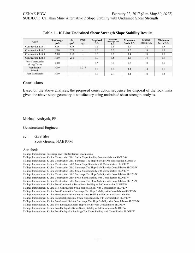
CENAE-EDW February 22, 2017 (Rev. May 30, 2017) SUBJECT: Callahan Mine Alternative 2 Slope Stability with Undrained Shear Strength
Table 1 – K-Line Undrained Shear Strength Slope Stability Results
Case Surcharge (psf)
Δq (psf)
PGA (g)
Required F.S.
Minimum Surcharge Toe
F.S.
Minimum Swale F.S.
Sliding Block F.S.
Minimum Berm F.S.
Construction Lift 1 625 625 - 1.3 1.6 1.7 1.8 1.5
Construction Lift 2 1000 375 - 1.3 2.3 1.5 1.8 1.5
Construction Lift 3 2000 250 - 1.3 1.7 1.4 1.8 1.5
Construction Lift 4 3000 250 - 1.3 1.5 1.3 1.8 1.5
Post-Construction (Long Term)
3000 - - 1.5 3.0 2.5 1.8 1.5
Pseudostatic Seismic
3000 - 0.215 1.0 1.8 1.4 1.4 1.1
Post-Earthquake 3000 - - 1.0 2.3 1.4 1.8 1.3
Conclusions
Based on the above analyses, the proposed construction sequence for disposal of the rock mass given the above slope geometry is satisfactory using undrained shear strength analysis.
Michael Andryuk, PE
Geostructural Engineer
cc: GES files Scott Greene, NAE PPM
Attached: Tailings Impoundment Surcharge and Total Settlement Calculations Tailings Impoundment K-Line Construction Lift 1 Swale Slope Stability Pre-consolidation SLOPE/W Tailings Impoundment K-Line Construction Lift 1 Surcharge Toe Slope Stability Pre-consolidation SLOPE/W Tailings Impoundment K-Line Construction Lift 2 Swale Slope Stability with Consolidation SLOPE/W Tailings Impoundment K-Line Construction Lift 2 Surcharge Toe Slope Stability with Consolidation SLOPE/W Tailings Impoundment K-Line Construction Lift 3 Swale Slope Stability with Consolidation SLOPE/W Tailings Impoundment K-Line Construction Lift 3 Surcharge Toe Slope Stability with Consolidation SLOPE/W Tailings Impoundment K-Line Construction Lift 4 Swale Slope Stability with Consolidation SLOPE/W Tailings Impoundment K-Line Construction Lift 4 Surcharge Toe Slope Stability with Consolidation SLOPE/W Tailings Impoundment K-Line Post-Construction Berm Slope Stability with Consolidation SLOPE/W Tailings Impoundment K-Line Post-Construction Swale Slope Stability with Consolidation SLOPE/W Tailings Impoundment K-Line Post-Construction Surcharge Toe Slope Stability with Consolidation SLOPE/W Tailings Impoundment K-Line Pseudostatic Seismic Berm Slope Stability with Consolidation SLOPE/W Tailings Impoundment K-Line Pseudostatic Seismic Swale Slope Stability with Consolidation SLOPE/W Tailings Impoundment K-Line Pseudostatic Seismic Surcharge Toe Slope Stability with Consolidation SLOPE/W Tailings Impoundment K-Line Post-Earthquake Berm Slope Stability with Consolidation SLOPE/W Tailings Impoundment K-Line Post-Earthquake Swale Slope Stability with Consolidation SLOPE/W Tailings Impoundment K-Line Post-Earthquake Surcharge Toe Slope Stability with Consolidation SLOPE/W
- 4 -
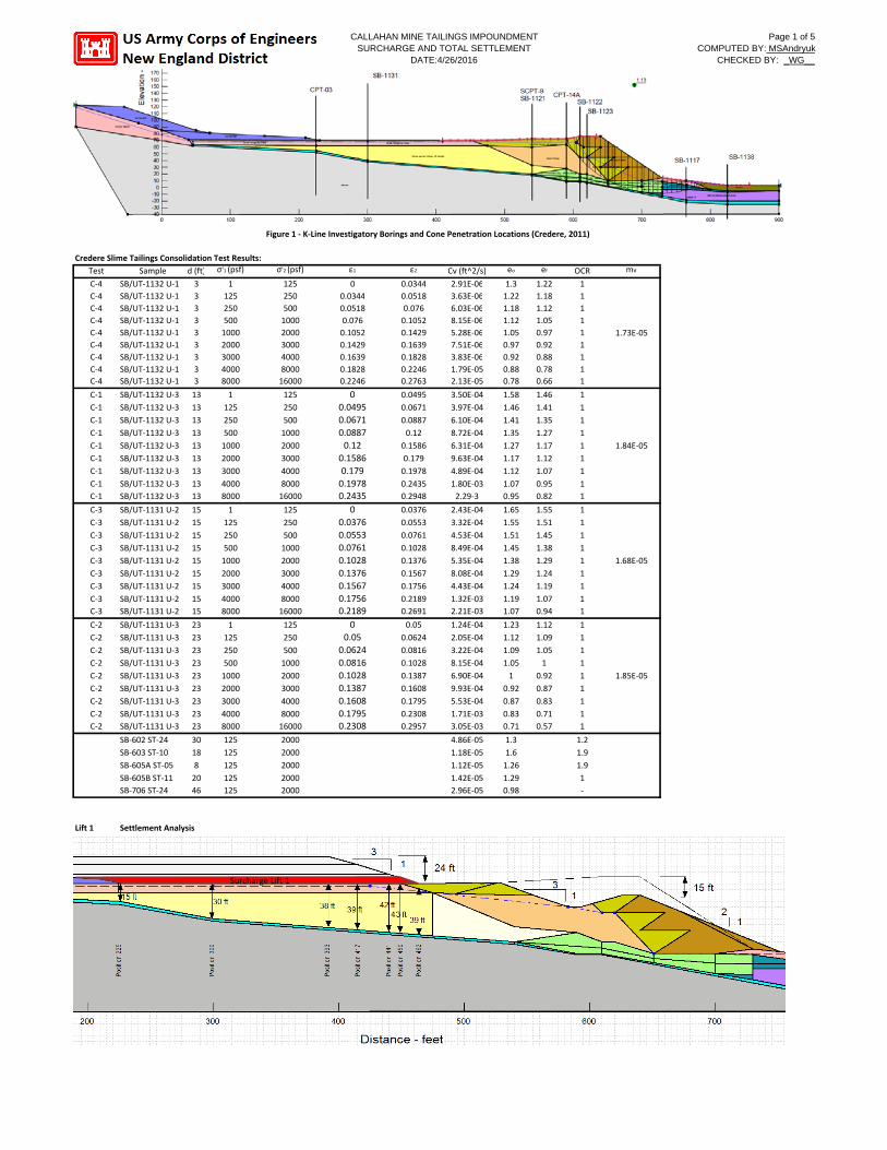
CALLAHAN MINE TAILINGS IMPOUNDMENT Page 1 of 5 SURCHARGE AND TOTAL SETTLEMENT COMPUTED BY: MSAndryuk
DATE:4/26/2016 CHECKED BY: _WG__
Figure 1 ‐ K‐Line Investigatory Borings and Cone Penetration Locations (Credere, 2011)
Credere Slime Tailings Consolidation Test Results:
Test Sample d (ft) σ'1 (psf) σ'2 (psf) ε1 ε2 Cv (ft^2/s) eo ef OCR mv
C‐4 C‐4 C‐4 C‐4 C‐4 C‐4 C‐4 C‐4 C‐4
SB/UT‐1132 U‐1 SB/UT‐1132 U‐1 SB/UT‐1132 U‐1 SB/UT‐1132 U‐1 SB/UT‐1132 U‐1 SB/UT‐1132 U‐1 SB/UT‐1132 U‐1 SB/UT‐1132 U‐1 SB/UT‐1132 U‐1
3 3 3 3 3 3 3 3 3
1 125 250 500 1000 2000 3000 4000 8000
125 250 500 1000 2000 3000 4000 8000 16000
0 0.0344 0.0518 0.076 0.1052 0.1429 0.1639 0.1828 0.2246
0.0344 0.0518 0.076 0.1052 0.1429 0.1639 0.1828 0.2246 0.2763
2.91E‐06 3.63E‐06 6.03E‐06 8.15E‐06 5.28E‐06 7.51E‐06 3.83E‐06 1.79E‐05 2.13E‐05
1.3 1.22 1.18 1.12 1.05 0.97 0.92 0.88 0.78
1.22 1.18 1.12 1.05 0.97 0.92 0.88 0.78 0.66
1 1 1 1 1 1 1 1 1
1.73E‐05
C‐1
C‐1
C‐1
C‐1
C‐1
C‐1
C‐1
C‐1 C‐1
SB/UT‐1132 U‐3
SB/UT‐1132 U‐3
SB/UT‐1132 U‐3
SB/UT‐1132 U‐3
SB/UT‐1132 U‐3
SB/UT‐1132 U‐3
SB/UT‐1132 U‐3
SB/UT‐1132 U‐3 SB/UT‐1132 U‐3
13
13
13
13
13
13
13
13 13
1
125
250
500
1000
2000
3000
4000 8000
125
250
500
1000
2000
3000
4000
8000 16000
0 0.0495 0.0671 0.0887 0.12
0.1586 0.179 0.1978 0.2435
0.0495
0.0671
0.0887
0.12
0.1586
0.179
0.1978
0.2435 0.2948
3.50E‐04
3.97E‐04
6.10E‐04
8.72E‐04
6.31E‐04
9.63E‐04
4.89E‐04
1.80E‐03 2.29‐3
1.58
1.46
1.41
1.35
1.27
1.17
1.12
1.07 0.95
1.46
1.41
1.35
1.27
1.17
1.12
1.07
0.95 0.82
1
1
1
1
1
1
1
1 1
1.84E‐05
C‐3
C‐3
C‐3
C‐3
C‐3
C‐3
C‐3
C‐3 C‐3
SB/UT‐1131 U‐2
SB/UT‐1131 U‐2
SB/UT‐1131 U‐2
SB/UT‐1131 U‐2
SB/UT‐1131 U‐2
SB/UT‐1131 U‐2
SB/UT‐1131 U‐2
SB/UT‐1131 U‐2 SB/UT‐1131 U‐2
15
15
15
15
15
15
15
15 15
1
125
250
500
1000
2000
3000
4000 8000
125
250
500
1000
2000
3000
4000
8000 16000
0 0.0376 0.0553 0.0761 0.1028 0.1376 0.1567 0.1756 0.2189
0.0376
0.0553
0.0761
0.1028
0.1376
0.1567
0.1756
0.2189 0.2691
2.43E‐04
3.32E‐04
4.53E‐04
8.49E‐04
5.35E‐04
8.08E‐04
4.43E‐04
1.32E‐03 2.21E‐03
1.65
1.55
1.51
1.45
1.38
1.29
1.24
1.19 1.07
1.55
1.51
1.45
1.38
1.29
1.24
1.19
1.07 0.94
1
1
1
1
1
1
1
1 1
1.68E‐05
C‐2
C‐2
C‐2
C‐2
C‐2
C‐2
C‐2
C‐2 C‐2
SB/UT‐1131 U‐3
SB/UT‐1131 U‐3
SB/UT‐1131 U‐3
SB/UT‐1131 U‐3
SB/UT‐1131 U‐3
SB/UT‐1131 U‐3
SB/UT‐1131 U‐3
SB/UT‐1131 U‐3 SB/UT‐1131 U‐3
23
23
23
23
23
23
23
23 23
1
125
250
500
1000
2000
3000
4000 8000
125
250
500
1000
2000
3000
4000
8000 16000
0 0.05
0.0624 0.0816 0.1028 0.1387 0.1608 0.1795 0.2308
0.05
0.0624
0.0816
0.1028
0.1387
0.1608
0.1795
0.2308 0.2957
1.24E‐04
2.05E‐04
3.22E‐04
8.15E‐04
6.90E‐04
9.93E‐04
5.53E‐04
1.71E‐03 3.05E‐03
1.23
1.12
1.09
1.05
1
0.92
0.87
0.83 0.71
1.12
1.09
1.05
1
0.92
0.87
0.83
0.71 0.57
1
1
1
1
1
1
1
1 1
1.85E‐05
SB‐602 ST‐24
SB‐603 ST‐10
SB‐605A ST‐05
SB‐605B ST‐11 SB‐706 ST‐24
30
18
8
20 46
125
125
125
125 125
2000
2000
2000
2000 2000
4.86E‐05
1.18E‐05
1.12E‐05
1.42E‐05 2.96E‐05
1.3
1.6
1.26
1.29 0.98
1.2
1.9
1.9
1 ‐
Lift 1 Settlement Analysis
Surcharge Lift 1
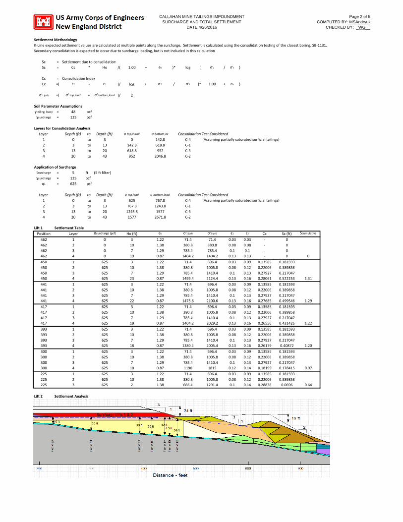
CALLAHAN MINE TAILINGS IMPOUNDMENT Page 2 of 5 SURCHARGE AND TOTAL SETTLEMENT COMPUTED BY: MSAndryuk
DATE:4/26/2016 CHECKED BY: _WG__
Settlement Methodology K‐Line expected settlement values are calculated at multiple points along the surcharge. Settlement is calculated using the consolidation testing of the closest boring, SB‐1131. Secondary consolidation is expected to occur due to surcharge loading, but is not included in this calculation
Sc = Settlement due to consolidation Sc = Cc * Ho /( 1.00 + eo )* log ( σ'2 / σ'1 )
Cc = Consolidation Index Cc =( ε2 ‐ ε1 )/ log ( σ'2 / σ'1 )*( 1.00 + eo )
σ'1 (psf) =( σ' top,load + σ' bottom,load )/ 2
Soil Parameter Assumptions ɣtailing, buoy = 48 pcf ɣsurcharge = 125 pcf
Layers for Consolidation Analysis: Layer Depth (ft) to Depth (ft) σ top,initial σ bottom,ini Consolidation Test Considered 1 0 to 3 0 142.8 C‐4 (Assuming partially saturated surficial tailings) 2 3 to 13 142.8 618.8 C‐1 3 13 to 20 618.8 952 C‐3 4 20 to 43 952 2046.8 C‐2
Application of Surcharge tsurcharge = 5 ft (5 ft filter) ɣsurcharge = 125 pcf
q1 = 625 psf
Layer Depth (ft) to Depth (ft) σ top,load σ bottom,load Consolidation Test Considered 1 0 to 3 625 767.8 C‐4 (Assuming partially saturated surficial tailings) 2 3 to 13 767.8 1243.8 C‐1 3 13 to 20 1243.8 1577 C‐3 4 20 to 43 1577 2671.8 C‐2
Lift 1 Settlement Table
Position Layer Δsurcharge (psf) Ho (ft) eo σ'1 (psf) σ'2 (psf) ε1 ε2 Cc Sc (ft) Scumulative
462 462 462 462
1 2 3 4
0 0 0 0
3 10 7 19
1.22 1.38 1.29 0.87
71.4 380.8 785.4 1404.2
71.4 380.8 785.4 1404.2
0.03 0.08 0.1 0.13
0.03 0.08 0.1 0.13
‐
‐
‐
‐
0 0 0 0 0
450 450 450 450
1 2 3 4
625 625 625 625
3 10 7 23
1.22 1.38 1.29 0.87
71.4 380.8 785.4 1499.4
696.4 1005.8 1410.4 2124.4
0.03 0.08 0.1 0.13
0.09 0.12 0.13 0.16
0.13585 0.22006 0.27927 0.28061
0.181593 0.389858 0.217047 0.522253 1.31
441 441 441 441
1 2 3 4
625 625 625 625
3 10 7 22
1.22 1.38 1.29 0.87
71.4 380.8 785.4 1475.6
696.4 1005.8 1410.4 2100.6
0.03 0.08 0.1 0.13
0.09 0.12 0.13 0.16
0.13585 0.22006 0.27927 0.27685
0.181593 0.389858 0.217047 0.499546 1.29
417 417 417 417
1 2 3 4
625 625 625 625
3 10 7 19
1.22 1.38 1.29 0.87
71.4 380.8 785.4 1404.2
696.4 1005.8 1410.4 2029.2
0.03 0.08 0.1 0.13
0.09 0.12 0.13 0.16
0.13585 0.22006 0.27927 0.26556
0.181593 0.389858 0.217047 0.431426 1.22
393 393 393 393
1 2 3 4
625 625 625 625
3 10 7 18
1.22 1.38 1.29 0.87
71.4 380.8 785.4 1380.4
696.4 1005.8 1410.4 2005.4
0.03 0.08 0.1 0.13
0.09 0.12 0.13 0.16
0.13585 0.22006 0.27927 0.26179
0.181593 0.389858 0.217047 0.40872 1.20
300 300 300 300
1 2 3 4
625 625 625 625
3 10 7 10
1.22 1.38 1.29 0.87
71.4 380.8 785.4 1190
696.4 1005.8 1410.4 1815
0.03 0.08 0.1 0.12
0.09 0.12 0.13 0.14
0.13585 0.22006 0.27927 0.18199
0.181593 0.389858 0.217047 0.178415 0.97
225 225 225
1 2 3
625 625 625
3 10 2
1.22 1.38 1.38
71.4 380.8 666.4
696.4 1005.8 1291.4
0.03 0.08 0.1
0.09 0.12 0.14
0.13585 0.22006 0.28838
0.181593 0.389858 0.0696 0.64
Lift 2 Settlement Analysis
Surcharge Lifts 1 & 2
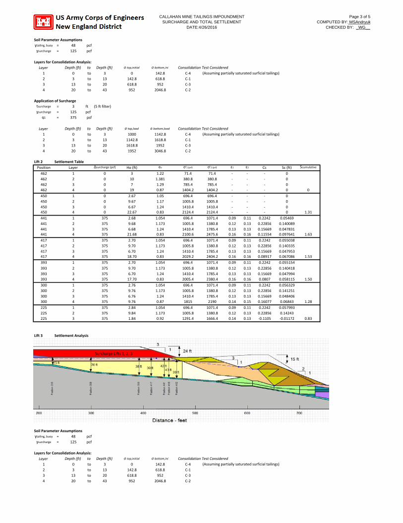
CALLAHAN MINE TAILINGS IMPOUNDMENT Page 3 of 5 SURCHARGE AND TOTAL SETTLEMENT COMPUTED BY: MSAndryuk
DATE:4/26/2016 CHECKED BY: _WG__
Soil Parameter Assumptions ɣtailing, buoy = 48 ɣsurcharge = 125
pcf pcf
Layers for Consolidation Analysis: Layer Depth (ft) to 1 0 to 2 3 to 3 13 to 4 20 to
Depth (ft) 3 13 20 43
σ top,initial
0 142.8 618.8 952
σ bottom,ini
142.8 618.8 952
2046.8
Consolidation Test Considered C‐4 (Assuming partially saturated surficial tailings) C‐1 C‐3 C‐2
Application of Surcharge tsurcharge = 3 ɣsurcharge = 125
q1 = 375
ft (5 ft filter) pcf psf
Layer 1 2 3 4
Depth (ft) 0 3 13 20
to to to to to
Depth (ft) 3 13 20 43
σ top,load
1000 1142.8 1618.8 1952
σ bottom,load
1142.8 1618.8 1952 3046.8
Consolidation Test Considered C‐4 (Assuming partially saturated surficial tailings) C‐1 C‐3 C‐2
Lift 2 Settlement Table
Position Layer Δsurcharge (psf) Ho (ft) eo σ'1 (psf) σ'2 (psf) ε1 ε2 Cc Sc (ft) Scumulative
462 462 462 462
1 2 3 4
0 0 0 0
3 10 7 19
1.22 1.381 1.29 0.87
71.4 380.8 785.4 1404.2
71.4 380.8 785.4 1404.2
‐
‐
‐
‐
‐
‐
‐
‐
‐
‐
‐
‐
0 0 0 0 0
450 450 450 450
1 2 3 4
0 0 0 0
2.67 9.67 6.67 22.67
1.05 1.17 1.24 0.83
696.4 1005.8 1410.4 2124.4
696.4 1005.8 1410.4 2124.4
‐
‐
‐‐
‐
‐
‐‐
‐
‐
‐‐
0 0 0 0 1.31
441 441 441 441
1 2 3 4
375 375 375 375
2.68 9.68 6.68 21.68
1.054 1.173 1.24 0.83
696.4 1005.8 1410.4 2100.6
1071.4 1380.8 1785.4 2475.6
0.09 0.12 0.13 0.16
0.11 0.13 0.13 0.16
0.2242 0.22856 0.15669 0.11554
0.05469 0.140089 0.047831 0.097641 1.63
417 417 417 417
1 2 3 4
375 375 375 375
2.70 9.70 6.70 18.70
1.054 1.173 1.24 0.83
696.4 1005.8 1410.4 2029.2
1071.4 1380.8 1785.4 2404.2
0.09 0.12 0.13 0.16
0.11 0.13 0.13 0.16
0.2242 0.22856 0.15669 0.08917
0.055038 0.140335 0.047953 0.067086 1.53
393
393 393 393
1
2 3 4
375
375 375 375
2.70
9.70 6.70 17.70
1.054
1.173 1.24 0.83
696.4
1005.8 1410.4 2005.4
1071.4
1380.8 1785.4 2380.4
0.09
0.12 0.13 0.16
0.11
0.13 0.13 0.16
0.2242
0.22856 0.15669 0.0807
0.055154
0.140418 0.047994 0.058115 1.50
300 300 300 300
1 2 3 4
375 375 375 375
2.76 9.76 6.76 9.76
1.054 1.173 1.24 0.87
696.4 1005.8 1410.4 1815
1071.4 1380.8 1785.4 2190
0.09 0.12 0.13 0.14
0.11 0.13 0.13 0.15
0.2242 0.22856 0.15669 0.16077
0.056329 0.141251 0.048406 0.06843 1.28
225 225 225
1 2 3
375 375 375
2.84 9.84 1.84
1.054 1.173 0.92
696.4 1005.8 1291.4
1071.4 1380.8 1666.4
0.09 0.12 0.14
0.11 0.13 0.13
0.2242 0.22856 ‐0.1105
0.057993 0.14243 ‐0.01172 0.83
Lift 3 Settlement Analysis
Surcharge Lifts 1, 2, 3
Soil Parameter Assumptions ɣtailing, buoy = 48 pcf ɣsurcharge = 125 pcf
Layers for Consolidation Analysis: Layer Depth (ft) to Depth (ft) σ top,initial σ bottom,ini Consolidation Test Considered 1 0 to 3 0 142.8 C‐4 (Assuming partially saturated surficial tailings) 2 3 to 13 142.8 618.8 C‐1 3 13 to 20 618.8 952 C‐3 4 20 to 43 952 2046.8 C‐2
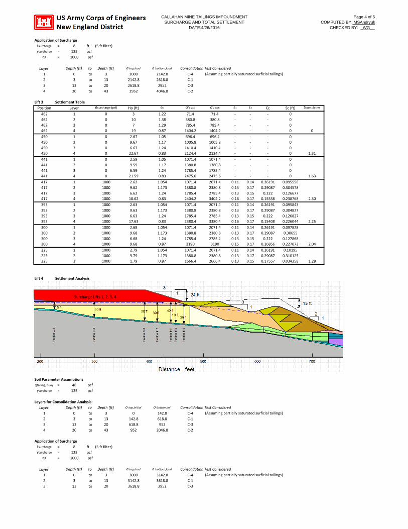
CALLAHAN MINE TAILINGS IMPOUNDMENT Page 4 of 5 SURCHARGE AND TOTAL SETTLEMENT COMPUTED BY: MSAndryuk
DATE:4/26/2016 CHECKED BY: _WG__
Application of Surcharge tsurcharge = 8 ɣsurcharge = 125
q1 = 1000
ft (5 ft filter) pcf psf
Layer 1 2 3 4
Depth (ft) 0 3 13 20
to to to to to
Depth (ft) 3 13 20 43
σ top,load
2000 2142.8 2618.8 2952
σ bottom,load
2142.8 2618.8 2952 4046.8
Consolidation Test Considered C‐4 (Assuming partially saturated surficial tailings) C‐1 C‐3 C‐2
Lift 3 Settlement Table
Position Layer Δsurcharge (psf) Ho (ft) eo σ'1 (psf) σ'2 (psf) ε1 ε2 Cc Sc (ft) Scumulative
462 462 462 462
1 2 3 4
0 0 0 0
3 10 7 19
1.22 1.38 1.29 0.87
71.4 380.8 785.4 1404.2
71.4 380.8 785.4 1404.2
‐
‐
‐
‐
‐
‐
‐
‐
‐
‐
‐
‐
0 0 0 0 0
450 450 450 450
1 2 3 4
0 0 0 0
2.67 9.67 6.67 22.67
1.05 1.17 1.24 0.83
696.4 1005.8 1410.4 2124.4
696.4 1005.8 1410.4 2124.4
‐
‐
‐
‐
‐
‐
‐
‐
‐
‐
‐
‐
0 0 0 0 1.31
441 441 441 441
1 2 3 4
0 0 0 0
2.59 9.59 6.59 21.59
1.05 1.17 1.24 0.83
1071.4 1380.8 1785.4 2475.6
1071.4 1380.8 1785.4 2475.6
‐
‐
‐
‐
‐
‐
‐
‐
‐
‐
‐
‐
0 0 0 0 1.63
417 417 417 417
1 2 3 4
1000 1000 1000 1000
2.62 9.62 6.62 18.62
1.054 1.173 1.24 0.83
1071.4 1380.8 1785.4 2404.2
2071.4 2380.8 2785.4 3404.2
0.11 0.13 0.13 0.16
0.14 0.17 0.15 0.17
0.26191 0.29087 0.222 0.15538
0.095556 0.304578 0.126677 0.238768 2.30
393 393 393 393
1 2 3 4
1000 1000 1000 1000
2.63 9.63 6.63 17.63
1.054 1.173 1.24 0.83
1071.4 1380.8 1785.4 2380.4
2071.4 2380.8 2785.4 3380.4
0.11 0.13 0.13 0.16
0.14 0.17 0.15 0.17
0.26191 0.29087 0.222 0.15408
0.095843 0.304827 0.126827 0.226044 2.25
300 300 300 300
1 2 3 4
1000 1000 1000 1000
2.68 9.68 6.68 9.68
1.054 1.173 1.24 0.87
1071.4 1380.8 1785.4 2190
2071.4 2380.8 2785.4 3190
0.11 0.13 0.13 0.15
0.14 0.17 0.15 0.17
0.26191 0.29087 0.222 0.26856
0.097828 0.30655 0.127868 0.227073 2.04
225 225 225
1 2 3
1000 1000 1000
2.79 9.79 1.79
1.054 1.173 0.87
1071.4 1380.8 1666.4
2071.4 2380.8 2666.4
0.11 0.13 0.13
0.14 0.17 0.15
0.26191 0.29087 0.17557
0.10195 0.310125 0.034358 1.28
Lift 4 Settlement Analysis
Surcharge Lifts 1, 2, 3, 4
Soil Parameter Assumptions ɣtailing, buoy = 48 ɣsurcharge = 125
pcf pcf
Layers for Consolidation Analysis: Layer Depth (ft) to 1 0 to 2 3 to 3 13 to 4 20 to
Depth (ft) 3 13 20 43
σ top,initial
0 142.8 618.8 952
σ bottom,ini
142.8 618.8 952
2046.8
Consolidation Test Considered C‐4 (Assuming partially saturated surficial tailings) C‐1 C‐3 C‐2
Application of Surcharge tsurcharge = 8 ɣsurcharge = 125
q1 = 1000
ft (5 ft filter) pcf psf
Layer 1 2 3
Depth (ft) 0 3 13
to to to to
Depth (ft) 3 13 20
σ top,load
3000 3142.8 3618.8
σ bottom,load
3142.8 3618.8 3952
Consolidation Test Considered C‐4 (Assuming partially saturated surficial tailings) C‐1 C‐3
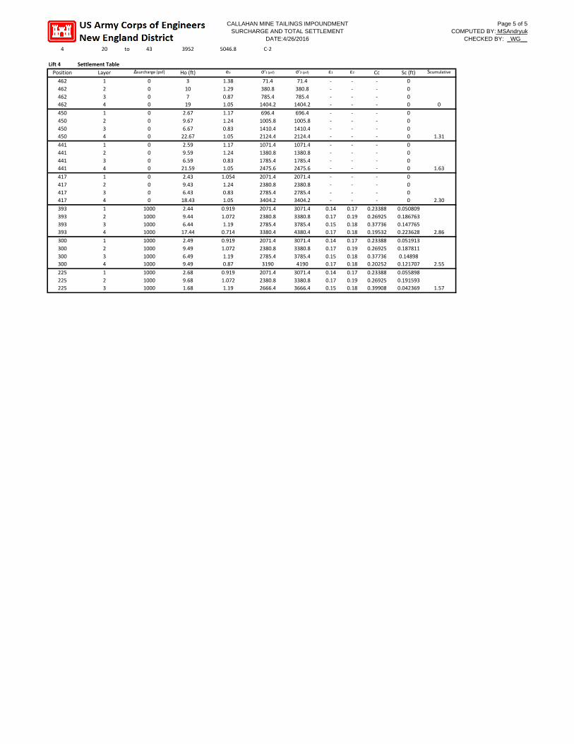
CALLAHAN MINE TAILINGS IMPOUNDMENT Page 5 of 5 SURCHARGE AND TOTAL SETTLEMENT COMPUTED BY: MSAndryuk
DATE:4/26/2016 CHECKED BY: _WG__
4 20 to 43 3952 5046.8 C‐2
Lift 4 Settlement Table
Position Layer Δsurcharge (psf) Ho (ft) eo σ'1 (psf) σ'2 (psf) ε1 ε2 Cc Sc (ft) Scumulative
462 462 462 462
1 2 3 4
0 0 0 0
3 10 7 19
1.38 1.29 0.87 1.05
71.4 380.8 785.4 1404.2
71.4 380.8 785.4 1404.2
‐
‐
‐
‐
‐
‐
‐
‐
‐
‐
‐
‐
0 0 0 0 0
450 450 450 450
1 2 3 4
0 0 0 0
2.67 9.67 6.67 22.67
1.17 1.24 0.83 1.05
696.4 1005.8 1410.4 2124.4
696.4 1005.8 1410.4 2124.4
‐
‐
‐
‐
‐
‐
‐
‐
‐
‐
‐
‐
0 0 0 0 1.31
441 441 441 441
1 2 3 4
0 0 0 0
2.59 9.59 6.59 21.59
1.17 1.24 0.83 1.05
1071.4 1380.8 1785.4 2475.6
1071.4 1380.8 1785.4 2475.6
‐
‐
‐
‐
‐
‐
‐
‐
‐
‐
‐
‐
0 0 0 0 1.63
417 417 417 417
1 2 3 4
0 0 0 0
2.43 9.43 6.43 18.43
1.054 1.24 0.83 1.05
2071.4 2380.8 2785.4 3404.2
2071.4 2380.8 2785.4 3404.2
‐
‐
‐
‐
‐
‐
‐
‐
‐
‐
‐
‐
0 0 0 0 2.30
393 393 393 393
1 2 3 4
1000 1000 1000 1000
2.44 9.44 6.44 17.44
0.919 1.072 1.19 0.714
2071.4 2380.8 2785.4 3380.4
3071.4 3380.8 3785.4 4380.4
0.14 0.17 0.15 0.17
0.17 0.19 0.18 0.18
0.23388 0.26925 0.37736 0.19532
0.050809 0.186763 0.147765 0.223628 2.86
300 300 300 300
1 2 3 4
1000 1000 1000 1000
2.49 9.49 6.49 9.49
0.919 1.072 1.19 0.87
2071.4 2380.8 2785.4 3190
3071.4 3380.8 3785.4 4190
0.14 0.17 0.15 0.17
0.17 0.19 0.18 0.18
0.23388 0.26925 0.37736 0.20252
0.051913 0.187811 0.14898 0.121707 2.55
225 225 225
1 2 3
1000 1000 1000
2.68 9.68 1.68
0.919 1.072 1.19
2071.4 2380.8 2666.4
3071.4 3380.8 3666.4
0.14 0.17 0.15
0.17 0.19 0.18
0.23388 0.26925 0.39908
0.055898 0.191593 0.042369 1.57

Bedrock
Consolidated Clay*
Medium Stiff Clay*
Consolidated Clay*
Mixed Tailings*
Berm (rock waste)*
Sand-like Tailings*
Granular Material*
Soft Clay*
Alluvium*
Consolidated Clay*
Glacial Till*
Granular Material*
Ore Pad Mat'l*
Medium Stiff Clay*
Slimes Tailings*
Slimes Tailings (Surcharged 8 feet)*
Slimes Tailings*
Ore Pad Mat'l*
Consolidated Clay*
Consolidated Clay*
Consolidated Clay*
Sand-like Tailings*
Glacial Till*
Consolidated Clay*
Consolidated Clay*
Medium Stiff Clay*
Sand-like Tailings*
Berm (rock waste)*
Sand-like Tailings*
Sand-like Tailings*
Slimes Tailings - Unconsolidated*
1.7
Ele
vatio
n - f
eet
-40
10
60
110
160
210
260
310
360
Color Name Model Unit Weight (pcf)
Cohesion' (psf)
Phi' (°)
Phi-B (°)
Piezometric Line
C-Topof Layer(psf)
C-Rate of Change ((lbs/ft²)/ft)
C-Maximum (psf)
C-Datum (psf)
Cu-Datum (psf)
Cu-Rate of Change ((lbs/ft²)/ft)
C/CuRatio
Datum (Elevation) (ft)
Berm (rock waste)*
Mohr-Coulomb 125 0 38 0
Bedrock (None) 1
Glacial Till* Mohr-Coulomb 130 0 35 0 1
Granular Material* Mohr-Coulomb 125 0 30 0 1
Sand-like Tailings* Mohr-Coulomb 110 0 34 0 1
Mixed Tailings* Mohr-Coulomb 110 0 30 0 1
Alluvium* Mohr-Coulomb 105 150 32 0 1
Slimes Tailings (Surcharged 8 feet)*
S=f(depth) 110 1 150 10 500
Medium Stiff Clay* Mohr-Coulomb 115 800 0 0 1
Ore Pad Mat'l* Mohr-Coulomb 150 0 38 0
Slimes Tailings* S=f(depth) 110 70 10 150
Soft Clay* Mohr-Coulomb 115 140 27 0 1
Consolidated Clay*
Mohr-Coulomb 115 200 26 0 1
Slimes Tailings - Unconsolidated*
Combined, S=f(datum)
110 0 1 10 150 150 10 1 62
3
3
1
1
1 2
Name: K-line - Lift 1 - Swale Stability Description: Current, long term existing condition - drained analysis File Name: Stability-K line-Surcharged-Undrained Pre Consolidation.gsz
Piezometric Line: 1
Khe: 0.1075g
15 ft
24 ft
*Value Taken From Credere Associates "2011 Supplemental GeotechnicalInvestigation Tailings Impoundment Area - OU1 Remedial Action"
70 + 10/ft
70 + 10/ft
70 + 10/ft
0 100 200 300 400 500 600 700 800 900
Distance - feet
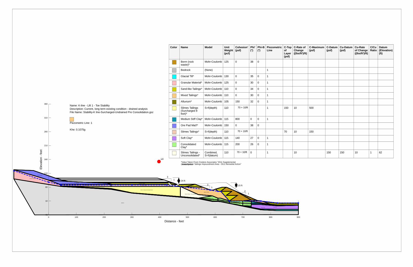
Bedrock
Consolidated Clay*
Medium Stiff Clay*
Consolidated Clay*
Mixed Tailings*
Berm (rock waste)*
Sand-like Tailings*
Granular Material*
Soft Clay*
Alluvium*
Consolidated Clay*
Glacial Till*
Granular Material*
Ore Pad Mat'l*
Medium Stiff Clay*
Slimes Tailings*
Slimes Tailings (Surcharged 8 feet)*
Slimes Tailings*
Ore Pad Mat'l*
Consolidated Clay*
Consolidated Clay*
Consolidated Clay*
Sand-like Tailings*
Glacial Till*
Consolidated Clay*
Consolidated Clay*
Medium Stiff Clay*
Sand-like Tailings*
Berm (rock waste)*
Sand-like Tailings*
Sand-like Tailings*
Slimes Tailings - Unconsolidated*
1.6
Ele
vatio
n - f
eet
-40
10
60
110
160
210
260
310
360
Color Name Model Unit Weight (pcf)
Cohesion' (psf)
Phi' (°)
Phi-B (°)
Piezometric Line
C-Topof Layer(psf)
C-Rate of Change ((lbs/ft²)/ft)
C-Maximum (psf)
C-Datum (psf)
Cu-Datum (psf)
Cu-Rate of Change ((lbs/ft²)/ft)
C/CuRatio
Datum (Elevation) (ft)
Berm (rock waste)*
Mohr-Coulomb 125 0 38 0
Bedrock (None) 1
Glacial Till* Mohr-Coulomb 130 0 35 0 1
Granular Material* Mohr-Coulomb 125 0 30 0 1
Sand-like Tailings* Mohr-Coulomb 110 0 34 0 1
Mixed Tailings* Mohr-Coulomb 110 0 30 0 1
Alluvium* Mohr-Coulomb 105 150 32 0 1
Slimes Tailings (Surcharged 8 feet)*
S=f(depth) 110 1 150 10 500
Medium Stiff Clay* Mohr-Coulomb 115 800 0 0 1
Ore Pad Mat'l* Mohr-Coulomb 150 0 38 0
Slimes Tailings* S=f(depth) 110 70 10 150
Soft Clay* Mohr-Coulomb 115 140 27 0 1
Consolidated Clay*
Mohr-Coulomb 115 200 26 0 1
Slimes Tailings - Unconsolidated*
Combined, S=f(datum)
110 0 1 10 150 150 10 1 62
3
3
1
1
1 2
Name: K-line - Lift 1 - Toe Stability Description: Current, long term existing condition - drained analysis File Name: Stability-K line-Surcharged-Undrained Pre Consolidation.gsz
Piezometric Line: 1
Khe: 0.1075g
15 ft
24 ft
*Value Taken From Credere Associates "2011 Supplemental GeotechnicalInvestigation Tailings Impoundment Area - OU1 Remedial Action"
70 + 10/ft
70 + 10/ft
70 + 10/ft
0 100 200 300 400 500 600 700 800 900
Distance - feet

1.5
Ele
vatio
n - f
eet
-40
10
60
110
160
210
260
310
360
(ps
Berm (rock waste)*
Mohr-Coulomb 125 0 38 0
Bedrock Bedrock (Impenetrable) 1
Glacial Till* Bedrock (Impenetrable) 1
Granular Material* Mohr-Coulomb 125 0 30 0 1
Sand-like Tailings* Mohr-Coulomb 110 0 34 0 1
Mixed Tailings* Mohr-Coulomb 110 0 30 0 1
Alluvium* Mohr-Coulomb 105 150 32 0 1
Slimes Tailings (below 08 feet)*
S=f(depth) 110 1 150
Medium Stiff Clay* Mohr-Coulomb 115 800 0 0 1
Ore Pad Mat'l* Mohr-Coulomb 150 0 38 0
Soft Clay* Mohr-Coulomb 115 200 26 0 1
Consolidated Clay*
Mohr-Coulomb 115 200 26 0 1
Slimes Tailings -Unconsolidated*
Combined, S=f(datum) 110 0 1
5
3 1
1
1 2
Name: K-line - Lift 2 - Undrained - Swale Stability Description: Current, long term existing condition - drained analysis File Name: Stability-K line-Surcharged-Undrained Post Consolidation-new.gsz
Piezometric Line: 1
Khe: 0.1075g
15 ft
24 ft
*Value Taken From Credere Associates "2011 Supplemental Geotechnical Investigation Tailings Impoundment Area - OU1 Remedial Action"
1%
0 100 200 300 400 500 600 700 800 900
Distance - feet
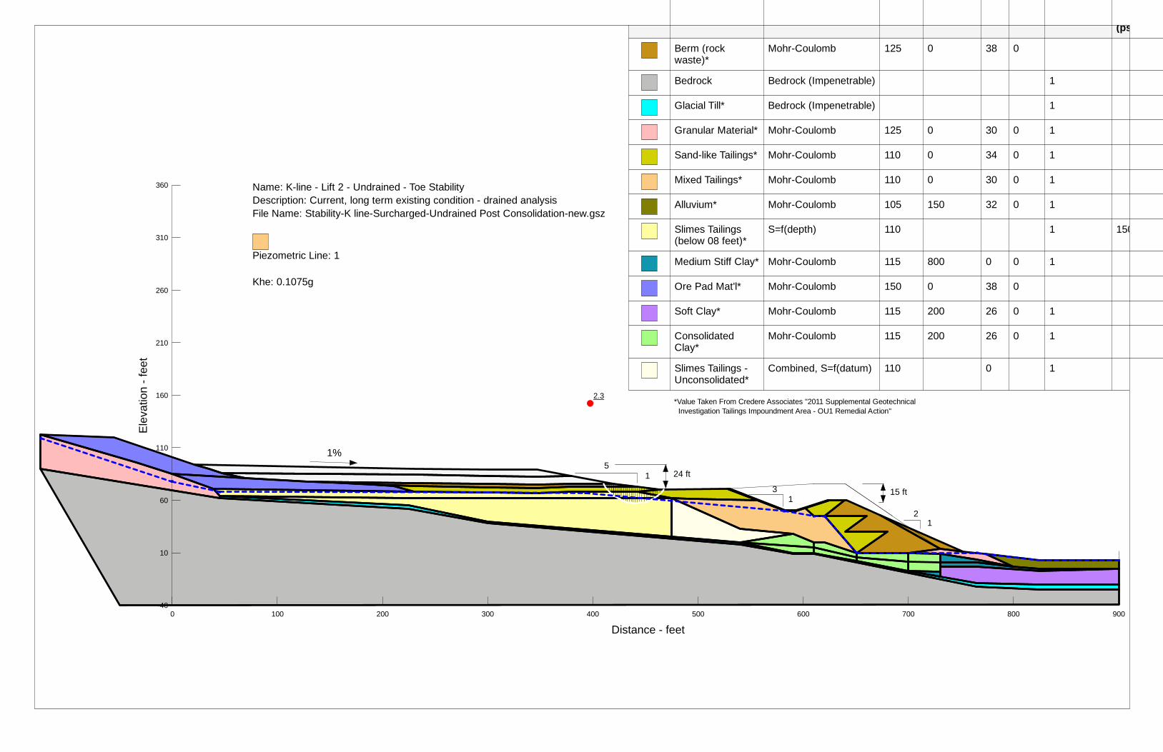
2.3
0 100 200 300 400 500 600 700 800 900
Ele
vatio
n - f
eet
-40
10
60
110
160
210
260
310
360
(ps
Berm (rock waste)*
Mohr-Coulomb 125 0 38 0
Bedrock Bedrock (Impenetrable) 1
Glacial Till* Bedrock (Impenetrable) 1
Granular Material* Mohr-Coulomb 125 0 30 0 1
Sand-like Tailings* Mohr-Coulomb 110 0 34 0 1
Mixed Tailings* Mohr-Coulomb 110 0 30 0 1
Alluvium* Mohr-Coulomb 105 150 32 0 1
Slimes Tailings (below 08 feet)*
S=f(depth) 110 1 150
Medium Stiff Clay* Mohr-Coulomb 115 800 0 0 1
Ore Pad Mat'l* Mohr-Coulomb 150 0 38 0
Soft Clay* Mohr-Coulomb 115 200 26 0 1
Consolidated Clay*
Mohr-Coulomb 115 200 26 0 1
Slimes Tailings -Unconsolidated*
Combined, S=f(datum) 110 0 1
5
3 1
1
1 2
Name: K-line - Lift 2 - Undrained - Toe Stability Description: Current, long term existing condition - drained analysis File Name: Stability-K line-Surcharged-Undrained Post Consolidation-new.gsz
Piezometric Line: 1
Khe: 0.1075g
15 ft
24 ft
*Value Taken From Credere Associates "2011 Supplemental Geotechnical Investigation Tailings Impoundment Area - OU1 Remedial Action"
1%
Distance - feet
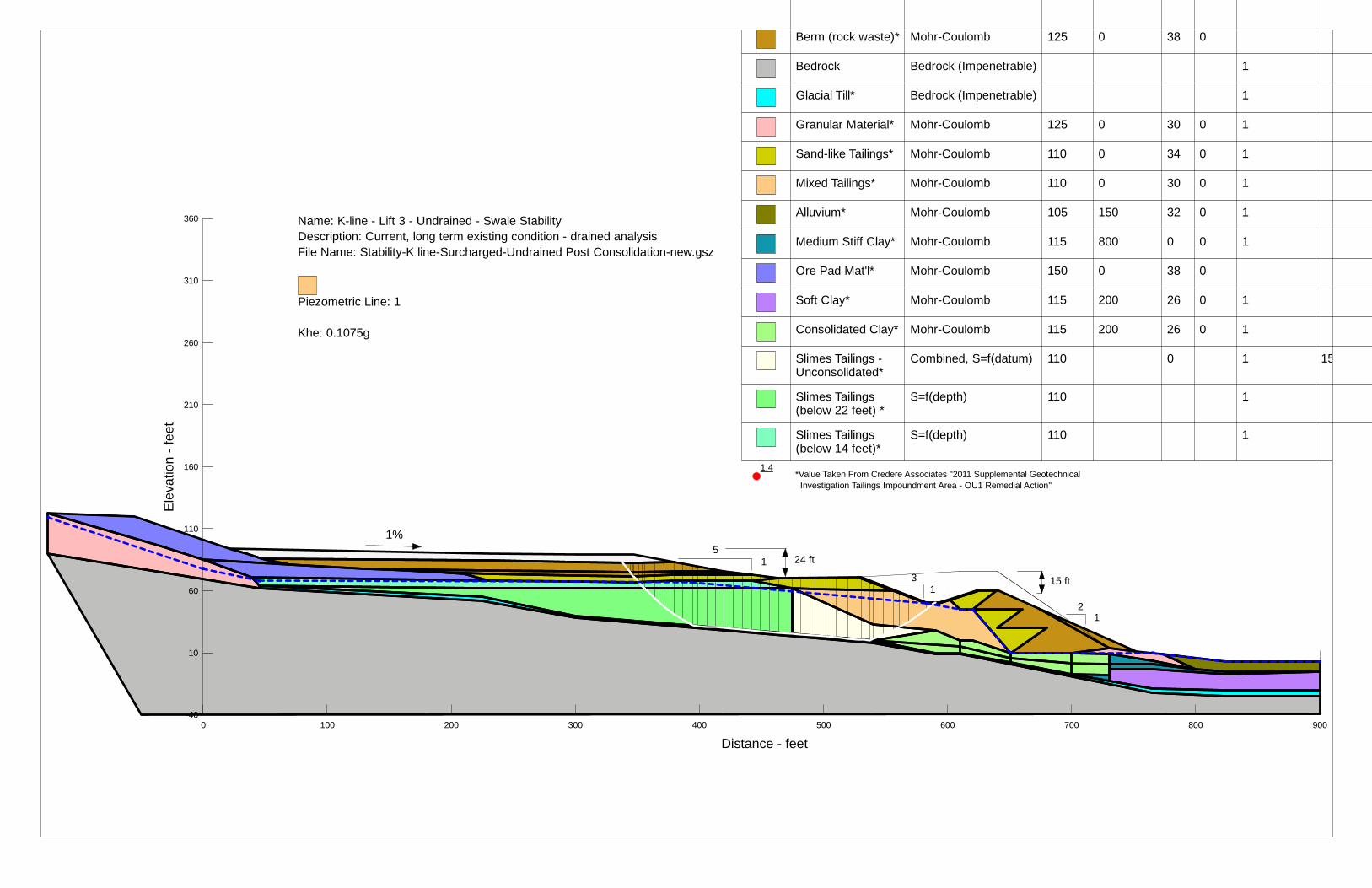
1.4
Ele
vatio
n - f
eet
-40
10
60
110
160
210
260
310
360
Berm (rock waste)* Mohr-Coulomb 125 0 38 0
Bedrock Bedrock (Impenetrable) 1
Glacial Till* Bedrock (Impenetrable) 1
Granular Material* Mohr-Coulomb 125 0 30 0 1
Sand-like Tailings* Mohr-Coulomb 110 0 34 0 1
Mixed Tailings* Mohr-Coulomb 110 0 30 0 1
Alluvium* Mohr-Coulomb 105 150 32 0 1
Medium Stiff Clay* Mohr-Coulomb 115 800 0 0 1
Ore Pad Mat'l* Mohr-Coulomb 150 0 38 0
Soft Clay* Mohr-Coulomb 115 200 26 0 1
Consolidated Clay* Mohr-Coulomb 115 200 26 0 1
Slimes Tailings -Unconsolidated*
Combined, S=f(datum) 110 0 1 15
Slimes Tailings (below 22 feet) *
S=f(depth) 110 1
Slimes Tailings (below 14 feet)*
S=f(depth) 110 1
5
3 1
1
1 2
Name: K-line - Lift 3 - Undrained - Swale Stability Description: Current, long term existing condition - drained analysis File Name: Stability-K line-Surcharged-Undrained Post Consolidation-new.gsz
Piezometric Line: 1
Khe: 0.1075g
15 ft
24 ft
*Value Taken From Credere Associates "2011 Supplemental Geotechnical Investigation Tailings Impoundment Area - OU1 Remedial Action"
1%
0 100 200 300 400 500 600 700 800 900
Distance - feet
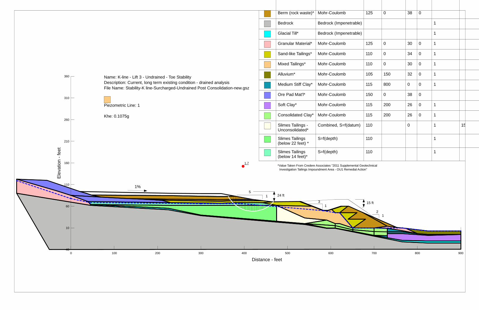
1.7
Ele
vatio
n - f
eet
-40
10
60
110
160
210
260
310
360
Berm (rock waste)* Mohr-Coulomb 125 0 38 0
Bedrock Bedrock (Impenetrable) 1
Glacial Till* Bedrock (Impenetrable) 1
Granular Material* Mohr-Coulomb 125 0 30 0 1
Sand-like Tailings* Mohr-Coulomb 110 0 34 0 1
Mixed Tailings* Mohr-Coulomb 110 0 30 0 1
Alluvium* Mohr-Coulomb 105 150 32 0 1
Medium Stiff Clay* Mohr-Coulomb 115 800 0 0 1
Ore Pad Mat'l* Mohr-Coulomb 150 0 38 0
Soft Clay* Mohr-Coulomb 115 200 26 0 1
Consolidated Clay* Mohr-Coulomb 115 200 26 0 1
Slimes Tailings -Unconsolidated*
Combined, S=f(datum) 110 0 1 15
Slimes Tailings (below 22 feet) *
S=f(depth) 110 1
Slimes Tailings (below 14 feet)*
S=f(depth) 110 1
5
3 1
1
1 2
Name: K-line - Lift 3 - Undrained - Toe Stability Description: Current, long term existing condition - drained analysis File Name: Stability-K line-Surcharged-Undrained Post Consolidation-new.gsz
Piezometric Line: 1
Khe: 0.1075g
15 ft
24 ft
*Value Taken From Credere Associates "2011 Supplemental Geotechnical Investigation Tailings Impoundment Area - OU1 Remedial Action"
1%
0 100 200 300 400 500 600 700 800 900
Distance - feet
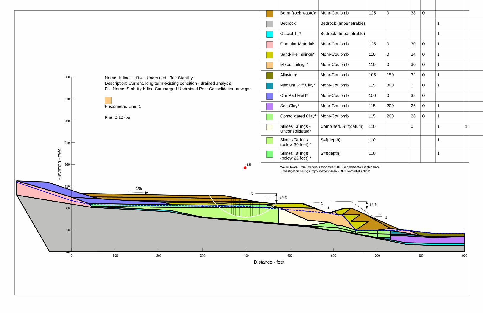
1.5
Ele
vatio
n - f
eet
-40
10
60
110
160
210
260
310
360
Berm (rock waste)* Mohr-Coulomb 125 0 38 0
Bedrock Bedrock (Impenetrable) 1
Glacial Till* Bedrock (Impenetrable) 1
Granular Material* Mohr-Coulomb 125 0 30 0 1
Sand-like Tailings* Mohr-Coulomb 110 0 34 0 1
Mixed Tailings* Mohr-Coulomb 110 0 30 0 1
Alluvium* Mohr-Coulomb 105 150 32 0 1
Medium Stiff Clay* Mohr-Coulomb 115 800 0 0 1
Ore Pad Mat'l* Mohr-Coulomb 150 0 38 0
Soft Clay* Mohr-Coulomb 115 200 26 0 1
Consolidated Clay* Mohr-Coulomb 115 200 26 0 1
Slimes Tailings -Unconsolidated*
Combined, S=f(datum) 110 0 1 15
Slimes Tailings (below 30 feet) *
S=f(depth) 110 1
Slimes Tailings (below 22 feet) *
S=f(depth) 110 1
5
3 1
1
1 2
Name: K-line - Lift 4 - Undrained - Toe Stability Description: Current, long term existing condition - drained analysis File Name: Stability-K line-Surcharged-Undrained Post Consolidation-new.gsz
Piezometric Line: 1
Khe: 0.1075g
15 ft
24 ft
*Value Taken From Credere Associates "2011 Supplemental Geotechnical Investigation Tailings Impoundment Area - OU1 Remedial Action"
1%
0 100 200 300 400 500 600 700 800 900
Distance - feet
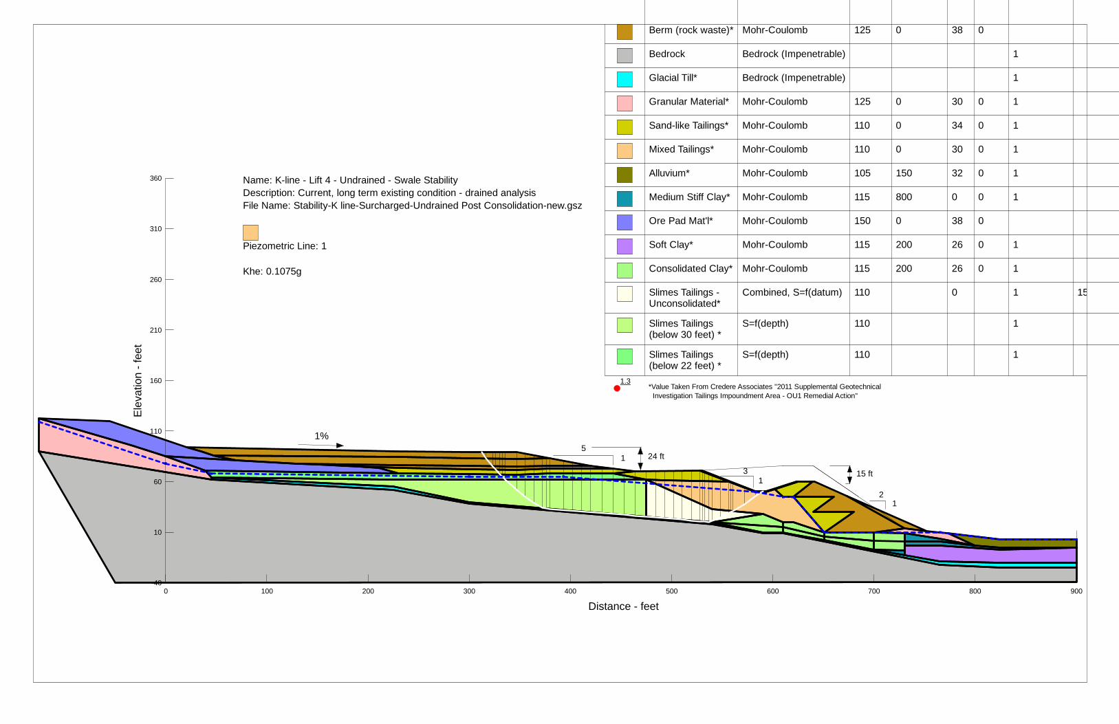
1.3
Ele
vatio
n - f
eet
-40
10
60
110
160
210
260
310
360
Berm (rock waste)* Mohr-Coulomb 125 0 38 0
Bedrock Bedrock (Impenetrable) 1
Glacial Till* Bedrock (Impenetrable) 1
Granular Material* Mohr-Coulomb 125 0 30 0 1
Sand-like Tailings* Mohr-Coulomb 110 0 34 0 1
Mixed Tailings* Mohr-Coulomb 110 0 30 0 1
Alluvium* Mohr-Coulomb 105 150 32 0 1
Medium Stiff Clay* Mohr-Coulomb 115 800 0 0 1
Ore Pad Mat'l* Mohr-Coulomb 150 0 38 0
Soft Clay* Mohr-Coulomb 115 200 26 0 1
Consolidated Clay* Mohr-Coulomb 115 200 26 0 1
Slimes Tailings -Unconsolidated*
Combined, S=f(datum) 110 0 1 15
Slimes Tailings (below 30 feet) *
S=f(depth) 110 1
Slimes Tailings (below 22 feet) *
S=f(depth) 110 1
5
3 1
1
1 2
Name: K-line - Lift 4 - Undrained - Swale Stability Description: Current, long term existing condition - drained analysis File Name: Stability-K line-Surcharged-Undrained Post Consolidation-new.gsz
Piezometric Line: 1
Khe: 0.1075g
15 ft
24 ft
*Value Taken From Credere Associates "2011 Supplemental Geotechnical Investigation Tailings Impoundment Area - OU1 Remedial Action"
1%
0 100 200 300 400 500 600 700 800 900
Distance - feet

1.5
Ele
vatio
n - f
eet
-40
10
60
110
160
210
260
310
360
Color Name Model Unit Weight (pcf)
Cohesion' (psf)
Phi' (°)
Phi-B (°)
Piezometric Line
Slimes Tailings Mohr-Coulomb 110 0 22 0 1
Berm (rock waste)* Mohr-Coulomb 125 0 38 0
Bedrock Bedrock (Impenetrable) 1
Glacial Till* Bedrock (Impenetrable) 1
Granular Material* Mohr-Coulomb 125 0 30 0 1
Sand-like Tailings* Mohr-Coulomb 110 0 34 0 1
Mixed Tailings* Mohr-Coulomb 110 0 30 0 1
Alluvium* Mohr-Coulomb 105 150 32 0 1
Medium Stiff Clay* Mohr-Coulomb 115 800 0 0 1
Ore Pad Mat'l* Mohr-Coulomb 150 0 38 0
Soft Clay* Mohr-Coulomb 115 200 26 0 1
Consolidated Clay* Mohr-Coulomb 115 200 26 0 1
5
3 1
1
1 2
Name: K-line - Long Term Post-Construction - Berm Stability Description: Current, long term existing condition - drained analysis File Name: Stability-K line-Surcharged-Undrained Post Consolidation-Cap.gsz
Piezometric Line: 1
15 ft
24 ft
*Value Taken From Credere Associates "2011 Supplemental Geotechnical Investigation Tailings Impoundment Area - OU1 Remedial Action"
1% Landfill Cap
0 100 200 300 400 500 600 700 800 900
Distance - feet

1.8
Ele
vatio
n - f
eet
-40
10
60
110
160
210
260
310
360
Color Name Model Unit Weight (pcf)
Cohesion' (psf)
Phi' (°)
Phi-B (°)
Piezometric Line
Slimes Tailings Mohr-Coulomb 110 0 22 0 1
Berm (rock waste)* Mohr-Coulomb 125 0 38 0
Bedrock Bedrock (Impenetrable) 1
Glacial Till* Bedrock (Impenetrable) 1
Granular Material* Mohr-Coulomb 125 0 30 0 1
Sand-like Tailings* Mohr-Coulomb 110 0 34 0 1
Mixed Tailings* Mohr-Coulomb 110 0 30 0 1
Alluvium* Mohr-Coulomb 105 150 32 0 1
Ore Pad Mat'l* Mohr-Coulomb 150 0 38 0
Clay Sliding Surface Bedrock (Impenetrable) 1
5
3 1
1
1 2
Name: K-line - Long Term Post-Construction - Sliding Block Description: Current, long term existing condition - drained analysis File Name: Stability-K line-Surcharged-Undrained Post Consolidation-Cap.gsz
Piezometric Line: 1
15 ft
24 ft
*Value Taken From Credere Associates "2011 Supplemental Geotechnical Investigation Tailings Impoundment Area - OU1 Remedial Action"
1% Landfill Cap
0 100 200 300 400 500 600 700 800 900
Distance - feet
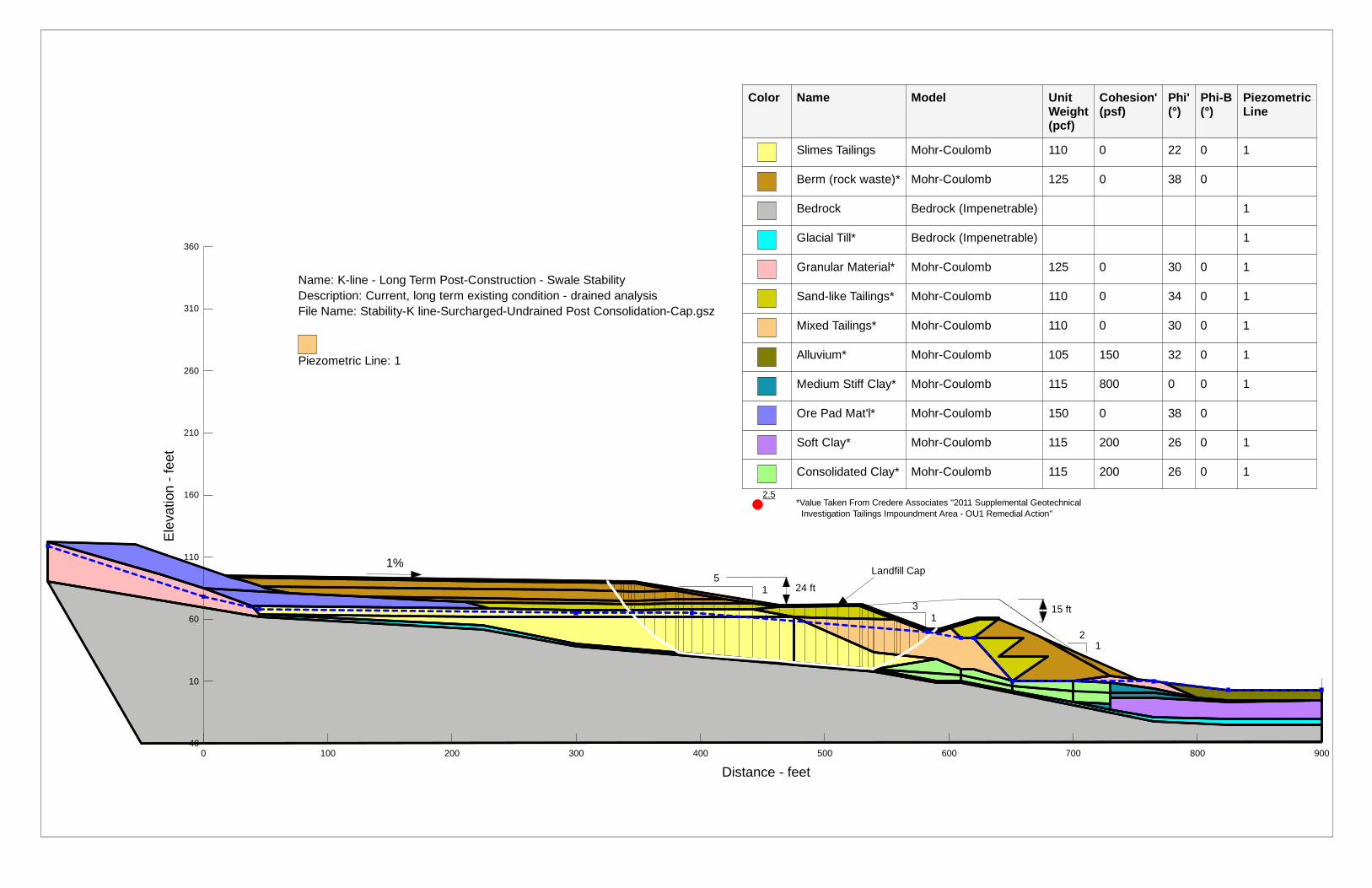
2.5
Ele
vatio
n - f
eet
-40
10
60
110
160
210
260
310
360
Color Name Model Unit Weight (pcf)
Cohesion' (psf)
Phi' (°)
Phi-B (°)
Piezometric Line
Slimes Tailings Mohr-Coulomb 110 0 22 0 1
Berm (rock waste)* Mohr-Coulomb 125 0 38 0
Bedrock Bedrock (Impenetrable) 1
Glacial Till* Bedrock (Impenetrable) 1
Granular Material* Mohr-Coulomb 125 0 30 0 1
Sand-like Tailings* Mohr-Coulomb 110 0 34 0 1
Mixed Tailings* Mohr-Coulomb 110 0 30 0 1
Alluvium* Mohr-Coulomb 105 150 32 0 1
Medium Stiff Clay* Mohr-Coulomb 115 800 0 0 1
Ore Pad Mat'l* Mohr-Coulomb 150 0 38 0
Soft Clay* Mohr-Coulomb 115 200 26 0 1
Consolidated Clay* Mohr-Coulomb 115 200 26 0 1
5
3 1
1
1 2
Name: K-line - Long Term Post-Construction - Swale Stability Description: Current, long term existing condition - drained analysis File Name: Stability-K line-Surcharged-Undrained Post Consolidation-Cap.gsz
Piezometric Line: 1
15 ft
24 ft
*Value Taken From Credere Associates "2011 Supplemental Geotechnical Investigation Tailings Impoundment Area - OU1 Remedial Action"
1% Landfill Cap
0 100 200 300 400 500 600 700 800 900
Distance - feet

3.0
Ele
vatio
n - f
eet
-40
10
60
110
160
210
260
310
360
Color Name Model Unit Weight (pcf)
Cohesion' (psf)
Phi' (°)
Phi-B (°)
Piezometric Line
Slimes Tailings Mohr-Coulomb 110 0 22 0 1
Berm (rock waste)* Mohr-Coulomb 125 0 38 0
Bedrock Bedrock (Impenetrable) 1
Glacial Till* Bedrock (Impenetrable) 1
Granular Material* Mohr-Coulomb 125 0 30 0 1
Sand-like Tailings* Mohr-Coulomb 110 0 34 0 1
Mixed Tailings* Mohr-Coulomb 110 0 30 0 1
Alluvium* Mohr-Coulomb 105 150 32 0 1
Medium Stiff Clay* Mohr-Coulomb 115 800 0 0 1
Ore Pad Mat'l* Mohr-Coulomb 150 0 38 0
Soft Clay* Mohr-Coulomb 115 200 26 0 1
Consolidated Clay* Mohr-Coulomb 115 200 26 0 1
5
3 1
1
1 2
Name: K-line - Long Term Post-Construction - Toe Stability Description: Current, long term existing condition - drained analysis File Name: Stability-K line-Surcharged-Undrained Post Consolidation-Cap.gsz
Piezometric Line: 1
15 ft
24 ft
*Value Taken From Credere Associates "2011 Supplemental Geotechnical Investigation Tailings Impoundment Area - OU1 Remedial Action"
1% Landfill Cap
0 100 200 300 400 500 600 700 800 900
Distance - feet

1.8
Ele
vatio
n - f
eet
-40
10
60
110
160
210
260
310
360
Color Name Model Unit Weight(pcf)
Cohesion' (psf)
Phi' (°)
Phi-B (°)
Piezometric Line
Slimes Tailings Mohr-Coulomb 110 0 22 0 1
Berm (rock waste)* Mohr-Coulomb 125 0 38 0
Bedrock Bedrock (Impenetrable) 1
Glacial Till* Bedrock (Impenetrable) 1
Granular Material* Mohr-Coulomb 125 0 30 0 1
Sand-like Tailings* Mohr-Coulomb 110 0 34 0 1
Mixed Tailings* Mohr-Coulomb 110 0 30 0 1
Alluvium* Mohr-Coulomb 105 150 32 0 1
Medium Stiff Clay* Mohr-Coulomb 115 800 0 0 1
Ore Pad Mat'l* Mohr-Coulomb 150 0 38 0
Soft Clay* Mohr-Coulomb 115 200 26 0 1
Consolidated Clay* Mohr-Coulomb 115 200 26 0 1
5
3 1
1
1 2
Name: K-line - Long Term Pseudostatic - Toe Stability Description: Current, long term existing condition - drained analysis File Name: Stability-K line-Surcharged-Post Consolidation EQ and Cap.gsz
Piezometric Line: 1
Khe: 0.1075g
15 ft
24 ft
*Value Taken From Credere Associates "2011 Supplemental Geotechnical Investigation Tailings Impoundment Area - OU1 Remedial Action"
1% Landfill Cap
0 100 200 300 400 500 600 700 800 900
Distance - feet
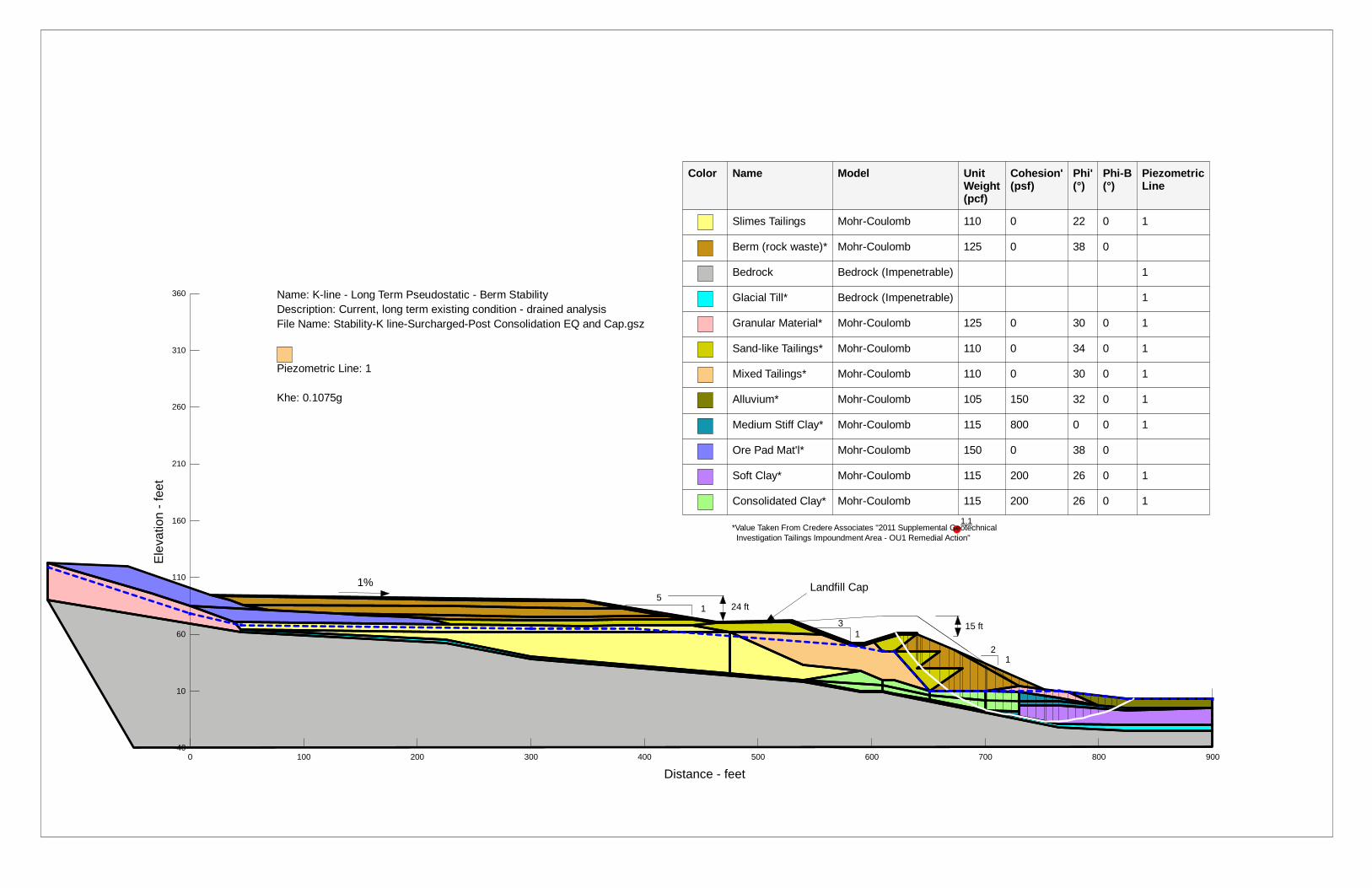
1.1
Ele
vatio
n - f
eet
-40
10
60
110
160
210
260
310
360
Color Name Model Unit Weight(pcf)
Cohesion' (psf)
Phi' (°)
Phi-B (°)
Piezometric Line
Slimes Tailings Mohr-Coulomb 110 0 22 0 1
Berm (rock waste)* Mohr-Coulomb 125 0 38 0
Bedrock Bedrock (Impenetrable) 1
Glacial Till* Bedrock (Impenetrable) 1
Granular Material* Mohr-Coulomb 125 0 30 0 1
Sand-like Tailings* Mohr-Coulomb 110 0 34 0 1
Mixed Tailings* Mohr-Coulomb 110 0 30 0 1
Alluvium* Mohr-Coulomb 105 150 32 0 1
Medium Stiff Clay* Mohr-Coulomb 115 800 0 0 1
Ore Pad Mat'l* Mohr-Coulomb 150 0 38 0
Soft Clay* Mohr-Coulomb 115 200 26 0 1
Consolidated Clay* Mohr-Coulomb 115 200 26 0 1
5
3 1
1
1 2
Name: K-line - Long Term Pseudostatic - Berm Stability Description: Current, long term existing condition - drained analysis File Name: Stability-K line-Surcharged-Post Consolidation EQ and Cap.gsz
Piezometric Line: 1
Khe: 0.1075g
15 ft
24 ft
*Value Taken From Credere Associates "2011 Supplemental Geotechnical Investigation Tailings Impoundment Area - OU1 Remedial Action"
1% Landfill Cap
0 100 200 300 400 500 600 700 800 900
Distance - feet
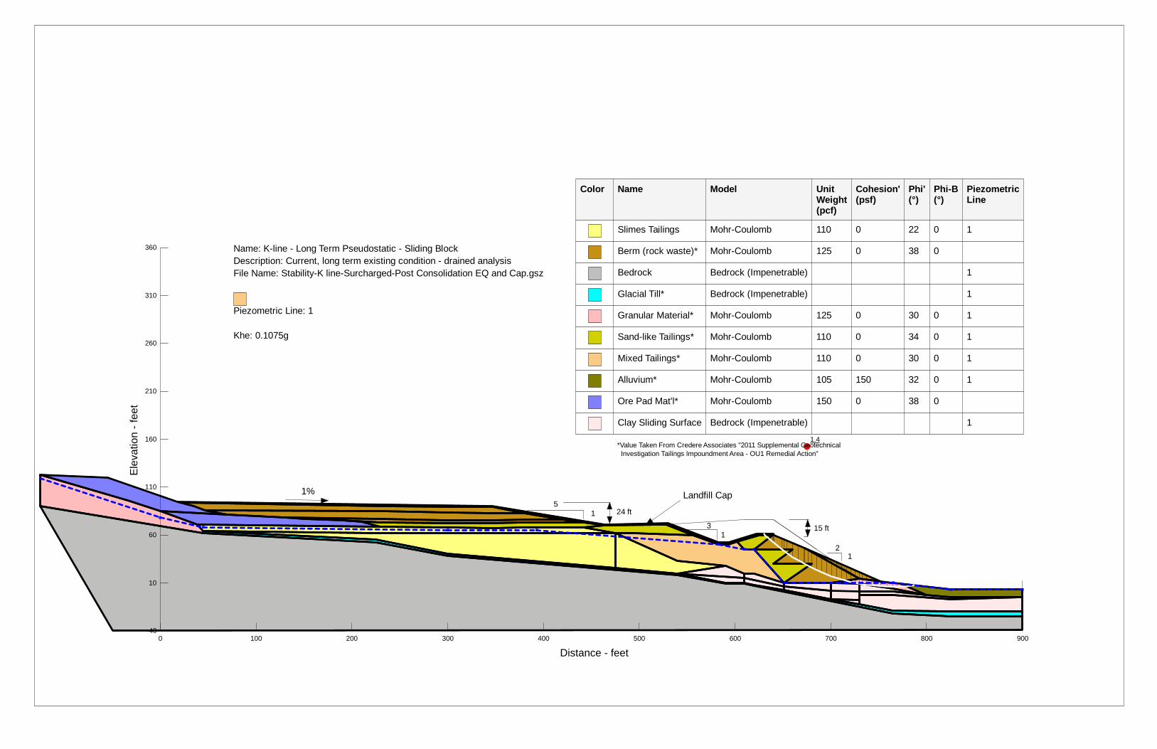
1.4
Ele
vatio
n - f
eet
-40
10
60
110
160
210
260
310
360
Color Name Model Unit Weight(pcf)
Cohesion' (psf)
Phi' (°)
Phi-B (°)
Piezometric Line
Slimes Tailings Mohr-Coulomb 110 0 22 0 1
Berm (rock waste)* Mohr-Coulomb 125 0 38 0
Bedrock Bedrock (Impenetrable) 1
Glacial Till* Bedrock (Impenetrable) 1
Granular Material* Mohr-Coulomb 125 0 30 0 1
Sand-like Tailings* Mohr-Coulomb 110 0 34 0 1
Mixed Tailings* Mohr-Coulomb 110 0 30 0 1
Alluvium* Mohr-Coulomb 105 150 32 0 1
Ore Pad Mat'l* Mohr-Coulomb 150 0 38 0
Clay Sliding Surface Bedrock (Impenetrable) 1
5
3 1
1
1 2
Name: K-line - Long Term Pseudostatic - Sliding Block Description: Current, long term existing condition - drained analysis File Name: Stability-K line-Surcharged-Post Consolidation EQ and Cap.gsz
Piezometric Line: 1
Khe: 0.1075g
15 ft
24 ft
*Value Taken From Credere Associates "2011 Supplemental Geotechnical Investigation Tailings Impoundment Area - OU1 Remedial Action"
1% Landfill Cap
0 100 200 300 400 500 600 700 800 900
Distance - feet

1.4
Ele
vatio
n - f
eet
-40
10
60
110
160
210
260
310
360
Color Name Model Unit Weight(pcf)
Cohesion' (psf)
Phi' (°)
Phi-B (°)
Piezometric Line
Slimes Tailings Mohr-Coulomb 110 0 22 0 1
Berm (rock waste)* Mohr-Coulomb 125 0 38 0
Bedrock Bedrock (Impenetrable) 1
Glacial Till* Bedrock (Impenetrable) 1
Granular Material* Mohr-Coulomb 125 0 30 0 1
Sand-like Tailings* Mohr-Coulomb 110 0 34 0 1
Mixed Tailings* Mohr-Coulomb 110 0 30 0 1
Alluvium* Mohr-Coulomb 105 150 32 0 1
Medium Stiff Clay* Mohr-Coulomb 115 800 0 0 1
Ore Pad Mat'l* Mohr-Coulomb 150 0 38 0
Soft Clay* Mohr-Coulomb 115 200 26 0 1
Consolidated Clay* Mohr-Coulomb 115 200 26 0 1
5
3 1
1
1 2
Name: K-line - Long Term Pseudostatic - Swale Stability Description: Current, long term existing condition - drained analysis File Name: Stability-K line-Surcharged-Post Consolidation EQ and Cap.gsz
Piezometric Line: 1
Khe: 0.1075g
15 ft
24 ft
*Value Taken From Credere Associates "2011 Supplemental Geotechnical Investigation Tailings Impoundment Area - OU1 Remedial Action"
1% Landfill Cap
0 100 200 300 400 500 600 700 800 900
Distance - feet

2.3
Ele
vatio
n - f
eet
-40
10
60
110
160
210
260
310
360
5
3 1
1
1 2
Name: K-line - Long Term Post-Earthquake - Toe Stability Description: Current, long term existing condition - drained analysis File Name: Stability-K line-Surcharged-Post Consolidation EQ and Cap.gsz
Piezometric Line: 1
Khe: 0.1075g
15 ft
24 ft
*Value Taken From Credere Associates "2011 Supplemental Geotechnical Investigation Tailings Impoundment Area - OU1 Remedial Action"
1% Landfill Cap
Color Name Model Unit Weight(pcf)
Cohesion' (psf)
Phi' (°)
Phi-B (°)
Piezometric Line
Steady State Strength (Css)(psf)
Collapse Surface Angle (°)
Berm (rock waste)* Mohr-Coulomb 125 0 38 0
Bedrock Bedrock (Impenetrable) 1
Glacial Till* Bedrock (Impenetrable) 1
Granular Material* Mohr-Coulomb 125 0 30 0 1
Sand-like Tailings* Mohr-Coulomb 110 0 34 0 1
Alluvium* Mohr-Coulomb 105 150 32 0 1
Medium Stiff Clay* Mohr-Coulomb 115 800 0 0 1
Ore Pad Mat'l* Mohr-Coulomb 150 0 38 0
Soft Clay* Mohr-Coulomb 115 200 26 0 1
Seismic Reduction Mixed Tailings
Mohr-Coulomb 110 0 22 0 1
Seismic Reduced Slimes Tailings
Mohr-Coulomb 110 0 16 0 1 0 0
Seismic Reduced Consolidated Clay
Mohr-Coulomb 115 160 21 0 1
0 100 200 300 400 500 600 700 800 900
Distance - feet

1.3
Ele
vatio
n - f
eet
-40
10
60
110
160
210
260
310
360
5
3 1
1
1 2
Name: K-line - Long Term Post-Earthquake - Berm Stability Description: Current, long term existing condition - drained analysis File Name: Stability-K line-Surcharged-Post Consolidation EQ and Cap.gsz
Piezometric Line: 1
Khe: 0.1075g
15 ft
24 ft
*Value Taken From Credere Associates "2011 Supplemental Geotechnical Investigation Tailings Impoundment Area - OU1 Remedial Action"
1% Landfill Cap
Color Name Model Unit Weight(pcf)
Cohesion' (psf)
Phi' (°)
Phi-B (°)
Piezometric Line
Steady State Strength (Css)(psf)
Collapse Surface Angle (°)
Berm (rock waste)* Mohr-Coulomb 125 0 38 0
Bedrock Bedrock (Impenetrable) 1
Glacial Till* Bedrock (Impenetrable) 1
Granular Material* Mohr-Coulomb 125 0 30 0 1
Sand-like Tailings* Mohr-Coulomb 110 0 34 0 1
Alluvium* Mohr-Coulomb 105 150 32 0 1
Medium Stiff Clay* Mohr-Coulomb 115 800 0 0 1
Ore Pad Mat'l* Mohr-Coulomb 150 0 38 0
Soft Clay* Mohr-Coulomb 115 200 26 0 1
Seismic Reduction Mixed Tailings
Mohr-Coulomb 110 0 22 0 1
Seismic Reduced Slimes Tailings
Mohr-Coulomb 110 0 16 0 1 0 0
Seismic Reduced Consolidated Clay
Mohr-Coulomb 115 160 21 0 1
0 100 200 300 400 500 600 700 800 900
Distance - feet
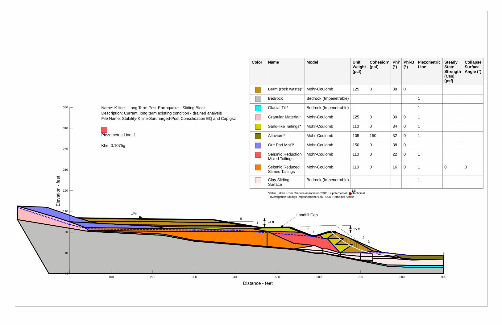
1.8
Ele
vatio
n - f
eet
-40
10
60
110
160
210
260
310
360
5
3 1
1
1 2
Name: K-line - Long Term Post-Earthquake - Sliding Block Description: Current, long term existing condition - drained analysis File Name: Stability-K line-Surcharged-Post Consolidation EQ and Cap.gsz
Piezometric Line: 1
Khe: 0.1075g
15 ft
24 ft
*Value Taken From Credere Associates "2011 Supplemental Geotechnical Investigation Tailings Impoundment Area - OU1 Remedial Action"
1% Landfill Cap
Color Name Model Unit Weight(pcf)
Cohesion' (psf)
Phi' (°)
Phi-B (°)
Piezometric Line
Steady State Strength (Css)(psf)
Collapse Surface Angle (°)
Berm (rock waste)* Mohr-Coulomb 125 0 38 0
Bedrock Bedrock (Impenetrable) 1
Glacial Till* Bedrock (Impenetrable) 1
Granular Material* Mohr-Coulomb 125 0 30 0 1
Sand-like Tailings* Mohr-Coulomb 110 0 34 0 1
Alluvium* Mohr-Coulomb 105 150 32 0 1
Ore Pad Mat'l* Mohr-Coulomb 150 0 38 0
Seismic Reduction Mixed Tailings
Mohr-Coulomb 110 0 22 0 1
Seismic Reduced Slimes Tailings
Mohr-Coulomb 110 0 16 0 1 0 0
Clay Sliding Surface
Bedrock (Impenetrable) 1
0 100 200 300 400 500 600 700 800 900
Distance - feet
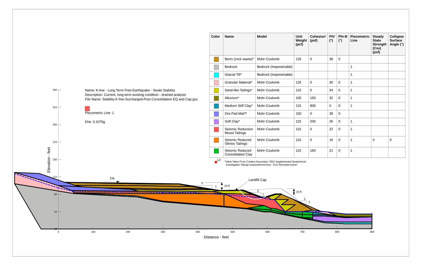
1.4
Ele
vatio
n - f
eet
-40
10
60
110
160
210
260
310
360
5
3 1
1
1 2
Name: K-line - Long Term Post-Earthquake - Swale Stability Description: Current, long term existing condition - drained analysis File Name: Stability-K line-Surcharged-Post Consolidation EQ and Cap.gsz
Piezometric Line: 1
Khe: 0.1075g
15 ft
24 ft
*Value Taken From Credere Associates "2011 Supplemental Geotechnical Investigation Tailings Impoundment Area - OU1 Remedial Action"
1% Landfill Cap
Color Name Model Unit Weight(pcf)
Cohesion' (psf)
Phi' (°)
Phi-B (°)
Piezometric Line
Steady State Strength (Css)(psf)
Collapse Surface Angle (°)
Berm (rock waste)* Mohr-Coulomb 125 0 38 0
Bedrock Bedrock (Impenetrable) 1
Glacial Till* Bedrock (Impenetrable) 1
Granular Material* Mohr-Coulomb 125 0 30 0 1
Sand-like Tailings* Mohr-Coulomb 110 0 34 0 1
Alluvium* Mohr-Coulomb 105 150 32 0 1
Medium Stiff Clay* Mohr-Coulomb 115 800 0 0 1
Ore Pad Mat'l* Mohr-Coulomb 150 0 38 0
Soft Clay* Mohr-Coulomb 115 200 26 0 1
Seismic Reduction Mixed Tailings
Mohr-Coulomb 110 0 22 0 1
Seismic Reduced Slimes Tailings
Mohr-Coulomb 110 0 16 0 1 0 0
Seismic Reduced Consolidated Clay
Mohr-Coulomb 115 160 21 0 1
0 100 200 300 400 500 600 700 800 900
Distance - feet