Embed Size (px)
Citation preview

INSTALLER: Leave ThisManual With
The Homeowner. HOME-OWNER:
Use and Care Information onPage 5.
INSTALADOR: Deje estemanual con el dueño de la
casa. DUEÑO DE LA CASA:Información acerca del uso ylos cuidados en la Página 5.
READ AND SAVETHESE INSTRUCTIONS
WARNING TO REDUCE THE RISK OF FIRE, ELECTRIC SHOCK,OR INJURY TO PERSONS, OBSERVE THE FOLLOW-ING:1. Use this unit only in the manner intended by the manu-
facturer. If you have questions, contact the manufac-turer at the address or telephone number listed inthe warranty.
2. Before servicing or cleaning unit, switch power off atservice panel and lock the service disconnectingmeans to prevent power from being switched on ac-cidentally. When the service disconnecting meanscannot be locked, securely fasten a prominent warn-ing device, such as a tag, to the service panel.
3. Installation work and electrical wiring must be doneby a qualified person(s) in accordance with all appli-cable codes and standards, including fire-rated con-struction codes and standards.
4. Sufficient air is needed for proper combustion and ex-hausting of gases through the flue (chimney) of fuelburning equipment to prevent backdrafting. Follow theheating equipment manufacturer’s guideline and safetystandards such as those published by the National FireProtection Association (NFPA), and the American So-ciety for Heating, Refrigeration and Air ConditioningEngineers (ASHRAE), and the local code authorities.
5. When cutting or drilling into wall or ceiling, do not dam-age electrical wiring and other hidden utilities.
6. Ducted fans must always be vented to the outdoors.7. Do not use this unit with any solid-state speed con-
trol device.8. To reduce the risk of fire, use only metal ductwork.9. Use with approved cord-connection kit only.10.This unit must be grounded.
TO REDUCE THE RISK OF A RANGE TOP GREASEFIRE:1. Never leave surface units unattended at high settings.
Boilovers cause smoking and greasy spillovers thatmay ignite. Heat oils slowly on low or medium set-tings.
2. Always turn hood ON when cooking at high heat orwhen cooking flaming foods.
3. Clean ventilation fans frequently. Grease should notbe allowed to accumulate on fan or filter.
4. Use proper pan size. Always use cookware appropri-ate for the size of the surface element.
TO REDUCE THE RISK OF INJURY TO PERSONS INTHE EVENT OF A RANGE TOP GREASE FIRE, OB-SERVE THE FOLLOWING:*1. SMOTHER FLAMES with a close-fitting lid, cookie
sheet, or metal tray, then turn off the burner. BE CARE-FUL TO PREVENT BURNS. If the flames do not go outimmediately, EVACUATE AND CALL THE FIRE DE-PARTMENT.
2. NEVER PICK UP A FLAMING PAN - You may beburned.
3. DO NOT USE WATER, including wet dishcloths ortowels - a violent steam explosion will result.
4. Use an extinguisher ONLY if:A. You know you have a Class ABC extinguisher and
you already know how to operate it.B. The fire is small and contained in the area where it
started.C. The fire department is being called.
IMPORTANTFor Non-ducted (Ductfree) Installation:a) Purchase non-ducted filter separately.b) Remove and discard damper/duct connector and
louver cover (See Step 4) in “Prepare the Hood,”Page 2.
c) Follow all steps except steps inside dotted lines.For Ducted Installation:Follow all steps, including steps inside dotted lines.
F40000 SERIES4-WAY CONVERTIBLERANGE HOOD
LEA Y CONSERVEESTAS INSTRUCCIONES
IMPORTANTEPara instalación sin ducto:a) Compra el filtro sin conductos separado.b) Quite y descarte el conector del regulador/ducto y la
tapa de la rejilla (Véase paso 4) en la Página 2 titulada“Prepare el extractor.”
c) Siga todos los pasos excepto de los pasos dentro laslíneas suspensivas.
Para instalación con ducto:Siga todos los pasos incluyendo los pasos dentro delas líneas suspensivas.
ADVERTENCIA PARA REDUCIR EL RIESGO DE INCENDIO, CHOQUE ELEC-TRICO, O LESION A PERSONAS, PROCURE LO SIGUIEN-TE:1. Utilice esta unidad sólo en la manera prescrita por el fabricante.
Si tiene usted alguna pregunta, comuníquese con el fabricantea la dirección o el teléfono indicados en la garantía.
2. Antes de limpiar o de poner en servicio la unidad, apague elinterruptor en el panel de servicio, y asegure el panel deservicio para evitar que se encienda accidentalmente. Cuandoel dispositivo para desconectar el servicio eléctrico no puedeser cerrado con algún tipo de traba, sujete fuertemente alpanel de servicio, una etiqueta de advertencia prominente.
3. Todo trabajo de instalación y cableado eléctrico debe serrealizado por personal calificado y de acuerdo con todos loscódigos y normas pertinentes, incluyendo los códigos ynormas relacionados con construcción clasificada paraincendio.
4. Aire suficiente es necesario para facilitar la combustiónadecuada y la salida apropiada de gases por la chimenea dela unidad y para evitar corrientes de aire invertidas. Siga lasinstrucciones y medidas de seguridad del fabricante del equipoy de las sociedades profesionales de equipos de calentadoresy los reglamentos de seguridad locales.
5. A cortar o perforar la pared o el techo, no dañe el cableadoeléctrico u otros servicios públicos ocultos a la vista.
6. Los abanicos con ducto deberán siempre tener una salidahacia el exterior.
7. No utilice esta unidad en conjunto con cualquier dispositivode control de velocidad de estado sólido.
8. Para reducir el riesgo de incendio, use sólo ductos de metal.9. Uso con el kit aprobado del la conexión de la cuerda
solamente.10. Esta unidad se debe instalar con tierra efectiva.
PARA REDUCIR EL RIESGO DE UN INCENDIO POR GRASAEN EN LA ESTUFA:1. Nunca deje sin atender las unidades de superficie cuando
tengan ajustes altos. Los reboses pueden provocar humo yderrames grasosos que se pueden incendiar. Calientelentamente el aceite en un ajuste bajo o medio.
2. Siempre ENCIENDA la campana cuando cocine con altatemperatura o cuando cocine alimentos que se puedanincendiar.
3. Limpie con frecuencia los ventiladores. No debe permitir quela grasa se acumule en el ventilador ni en el filtro.
4. Utilice un sartén de tamaño adecuado. Siempre utilice elutensilio adecuado al tamaño del elemento de superficie.
PARA REDUCIR EL RIESGO DE LESION A PERSONAS RE-SULTADO DE UN INCENDIO DEBIDO A GRASA ACUMULADAEN LAS HORNILLAS, PROCURE LO SIGUIENTE:*1. AHOGUE LAS LLAMAS con una tapa ajustada o charola de metal,
después apague la hornilla. TENGA CUIDADO A FIN DE EVITARQUEMADURAS. Si las llamas no se apagan de inmediato, EVACUEY AVISE A LOS BOMBEROS.
2. NO LEVANTE NUNCA UNA SARTEN QUE ESTE ENLLAMAS - Usted se podrá quemar.
3. NO UTILICE AGUA, incluyendo toallas de cocina mojadas -puede resultar una explosión de vapor violenta.
4. Utilice un extinguidor SOLAMENTE si:A. Usted sabe que tiene un extinguidor de clase
ABC y lo sabe utilizar.B. El incendio es pequeño y contenido dentro del
área donde se inició.C. Los bomberos han sido avisados.D. Usted puede combatir el incendio con una salida a
su espalda.* Basado en las recomendaciones para “Seguridad en laCocina” publicadas por la NFPA de los EEUU.
CAMPANA EXTRACTORA4-WAY CONVERTIBLESERIE F40000
! INTENDED FOR DOMESTICCOOKING ONLY. ! ! PREVISTO PARA COCINAR
DOMÉSTICO SOLAMENTE. !
To register this product visitwww.broan.com

D. You can fight the fire with your back to an exit.* Based on “Kitchen Fire Safety Tips” published byNFPA.
CAUTION !1. For general ventilating use only. Do not use to exhaust
hazardous or explosive materials and vapors.2. To avoid motor bearing damage and noisy and/
or unbalanced impellers, keep drywall spray,construction dust, etc. off power unit.
3. Your hood motor has a thermal overload which willautomatically shut off the motor if it becomesoverheated. The motor will restart when it coolsdown. If the motor continues to shut off and restart,have the hood serviced.
4. For best capture of cooking impurities, your range hoodshould be mounted 18-24" above the cooking surface.
5. Please read specification label on product for furtherinformation and requirements.
FIG. 1B
FIG. 1C
FIG. 1D
FIG. 1E
2
6" ROUND DUCT 406DUCTO REDONDO DE6" 406
3-1/4" x 10" TO 6"ROUND DUCTTRANSITION 411TRANSICIÓN DE3-1/4" x 10" AUN DUCTOREDONDODE 6" 411
WALL CAP 639 OR 649CASQUETE DE PARED 639 O 649
WALL CAP 639 OR 649CASQUETE DE PARED639 O 649
3-1/4" x 10" DUCT 401DUCTO DE 3-1/4" x 10" 401
ROOF CAP 634 OR 644CASQUETE DETECHO 634 O 644
3-1/4" x 10" DUCT 401DUCTO DE3-1/4" x 10" 401
ADJUSTABLE ELBOW 419CODO AJUSTABLE 419
WALL CAP 641CASQUETE DEPARED 641
3-1/4" x 10" TO 6"ROUND DUCTTRANSITION 411TRANSICIÓN DE3-1/4" x 10" AUN DUCTOREDONDODE 6" 411
ROOF CAP 634 OR 644CASQUETE DE TECHO 634 O 644
6" ROUNDDUCT 406DUCTOREDONDODE 6" 406
PRECAUCION !1. Solamente para uso general de ventilación. No utilice para
descargar materiales o vapores riesgosos o explosivos.2. Para evitar daños al motor y evitar que las navajas del
abanico emitan mucho ruido o estén fuera de balance,mantenga el motor libre de pelusa, polvo, etc.
3. El motor de su extractor tiene dispositivo de sobrecargatérmica, al cual automáticamente apagará el motor sise sobrecalienta. El motor funcionará de nuevo cuandose enfríe. Si el motor continua apagándose y arrancando,hágalo componer.
4. Para obtener mejores resultados en la captura de losvapores de la estufa, el extractor debe montarse a entre18 y 24 plg. sobre las hornillas de la estufa.
5. Por favor lea la etiqueta con las especificaciones delequipo para otros requisitos y mayor información.
HERRAMIENTAS YMATERIALES QUE SEREQUIERENHERRAMIENTAS
Taladro, eléctrico o trinqueteBroca tipo pala de 1-1/4"Destornillador de ranura o tipo phillipsPinzas o tenazasMedidor de cinta o regla y lápiz
Para instalaciones con ducto SOLAMENTE:Sierra tipo sable o sierra para tabiquesAlicate para cortar
MATERIALESSuministros y alambre eléctrico del tipo que cumplencon los códigos locales
Casquete de techo o paredCemento o pega de techa o material de calafatearo rellenarDuctos y cinta aislante para ductos
Para instalación en gabinetes de cocina con la parte infe-rior ahuecada solamente:
Dos tiras de madera 1" x 2" x 12" (largo aproximado)(cómpreselas localmente)Cuatro tornillos para madera de cabeza plana de 1-1/4"de largo (cómpreselas localmente) para sujetar las tirasde madera a la parte inferior de gabinete
PLANIFICANDO LAINSTALACION DE LOSDUCTOSComience el trabajo de los ductos decidiendo el caminoque el ducto tomará entre el extractor y la parte exteriorde la casa. Para mejor rendimiento, use el camino de ductomás corto posible y un mínimo de codos. Se muestranvarias elecciones - FIGS. 1A - 1E.En situaciones de paso del ducto más complejas, el ex-tractor con conexión para ducto rectangular puedeconvertirse en conexión redonda usando una transición.FIG. 1A. Pasando el ducto directamente a través de lapared (para los extractores que están instalados en unapared exterior). Se muestran dos maneras de pasar elducto a través de la pared exterior. Si se usa un casquetede pared directamente en la parte de atrás del extractorhay que asegurarse que el regulador en el conector entreducto y regulador en el extractor, y el regulador en elcasquete de pared no interfieran el uno con el otro cuandoel extractor esté operando. Esto podría resultar en pasode aire inadecuado o corrientes invertidas. Si estacondición existe, quite la hoja instalada en el reguladordel extractor. A veces cuando se usa un casquete de paredes más fácil pasar el ducto verticalmente y usar un codocomo se muestra en FIG. 1B.FIG. 1C. Haciendo un ducto directamente al techo usandoun ducto rectangular de 3-1/4" x 10" (para instalacionesen un piso solamente).FIG. 1D. Instalando un ducto entre las vigas del techo(para instalaciones en más de un piso) o a través delespacio de sofito arriba de los gabinetes (cuando el sofitoestá conectado a una pared exterior).FIG. 1E. Directamente hacia el techo usando transiciónde 3-1/4” x 10” a un ducto redondo de 6” y ducto redondode 6" (para instalaciones de un piso).FIG. 1F. Directamente hacia el techo usando ductoredondo de 7" (para instalaciones de un piso).
TOOLS ANDMATERIALS REQUIREDTOOLS
Drill, electric or ratchet drive1-1/4" Spade bitCommon head and phillips head screwdriverPliersTape measure or ruler and pencil
For Ducted Installations ONLY:Saber saw or drywall sawMetal snips
MATERIALSElectrical wiring and supplies of type to complywith local codesFor Ducted Installations Only:
Roof or wall capRoof cement or caulkDuct and duct tape
For Installation on Kitchen Cabinets with RecessedBottoms Only:
Two 1" x 2" x 12" (approximate length) wood strips(purchase locally)Four 1-1/4" long flat head wood screws (purchaselocally) to fasten strips to cabinet bottom
PLANNING DUCTWORKINSTALLATIONBegin planning ductwork by deciding where the ductwill run between the range hood and the outside. Forbest performance, use the shortest possible duct runand a minimum number of elbows. There are severalchoices shown - FIGS. 1A - 1E.In more complex ducting situations, a 3-1/4" rectan-gular ducting range hood can be converted to a roundduct by means of a transition.FIG. 1A. Ducting directly through the wall (for rangehoods mounted on an exterior wall). Shown are twoways to duct through an outside wall. If a wall cap isused directly off the back of the hood, special caremust be taken to make sure that the damper in thedamper/duct connector on the hood and damper inthe wall cap do not interfere with each other when thehood is operating. This could result in either inad-equate air delivery or back drafts. If this condition doesexist, remove the hood damper flap. Sometimes whenusing a wall cap it is easier to duct vertically and thenuse an elbow as shown in FIG. 1B.FIG. 1C. Ducting straight up through the roof using3-1/4" x 10" rectangular duct. (For single story in-stallations.)FIG. 1D. Ducting between the ceiling joists (for multi-story installations) or through the soffit space abovethe cabinets (where the soffit connects to an outsidewall).FIG. 1E. Straight up through the roof using 3-1/4” x10” to 6” round duct transition and 6" round duct (forsingle-story installations).FIG. 1F. Straight up through the roof using 7" roundduct (for single-story installations).
FIG. 1A
7" ROUND DUCT 407DUCTO REDONDO
DE 7” 407
MODEL BP87DAMPER
REGISTRODE TIRO
MODELO BP87
ROOF CAP 634CASQUETE DE
TECHO 634
FIG. 1F

3
FIG. 2
FIG. 5
FIG. 6
FIG. 7
CUT STRIPS TO FITCORTE LAS TIRAS PARAQUE QUEPAN
CENTER LINELINEA CENTRICA
WIDTH OFRANGE HOODANCHO DELEXTRACTOR
ELECTRICAL WIRING OPENINGABERTURA PARA ELCABLEADO ELECTRICO
PREPARANDO EL EXTRACTOR1. Desempaque el extractor y revise el contenido de la
caja. Usted debe de encontrar:1 - Filtro de aluminio1 - Conector de ducto/regulador de 3-1/4" x 10"
(montado dentro del extractor para embarquesolamente) (Guarde los tornillos para el monta-
je.)1 - Placa del conducto redondo de 7” (montado en
del extractor) (no se muestra) (Guarde los torni-llos para el montaje.)
2. Quite la placa del conducto redondo de 7” de la partesuperior de la campana. Colóquela aparte, con lostornillos de montaje.
3. Quite la cubierta de la caja de cableado. Bajo la tapaencontrará:1 - Una bolsa de plástico que contiene herrajes
sueltos para instalación
Para instalaciones sin ducto SOLAMENTE:4. Para instalaciones sin ducto, quite la tapa de la reji-
llas de la parte frontal del extractor. (FIG. 3)NOTA
Las rejillas que se encuentran al frente de la campanadeben estar abiertas y visibles para que la campana
funcione sin conducto.5. Quite la tapa de quitar golpeando eléctrica de arriba
o atrás dependiendo en donde entra el cableado alextractor de la pared o del gabinete. (FIG. 4)
INSTALACION CON DUCTO SOLAMENTENOTA
La cubierta de las rejillas se debe instalar como semuestra en la figura 3 para que funcione con el
conducto.6. Quite la placa de quitar golpeando en el extractor
insertando un destornillador en el filo y rompiendolas conexiones que lo sostienen al extractor. Esposible que tenga que golpear el destornillador conun martillo para romper estas uniones. Pele la tapade quitar golpeando hacia atrás con una tenaza.(FIG. 5)
7. Junte el conector del regulador/ducto sobre la aber-tura y sujételo en su sitio con tornillos negros demetal para lámina. (FIG. 6)Los pasadores de bisagra y el conector del regula-dor/ducto deben de estar hacia la parte de arribadel extractor para pasar el ducto a través de la pa-red o hacia la parte de atrás del extractor para pa-sar el ducto a través de gabinete encima delextractor. Selle la unión entre el conector regula-dor/ducto con cinta de ducto.
8. Sólo para descargas con conducto redondo de7”: Vuelva a instalar la placa del conducto redondode 7” que quitó en el paso 2 de la sección “PREPA-RANDO EL EXTRACTOR.” Para obtener un mejorrendimiento, alinee la placa del conducto redondode 17.8 cm (7”) con la abertura redonda de 17.8cm (7”) de la campana. Monte la placa del conduc-to a la campana con dos tornillos desde la placadel conducto y con dos tornillos desde el tiro de 8.3x 25.4 cm (3 ¼” x 10”). Instale un regulador de tiroredondo de 7” (se compra por separado). La aletadel regulador se debe abrir libremente en direccióndel flujo de aire (en sentido contrario a la campanade la estufa).
PREPARANDO LA UBICACIONDE LA INSTALACION
NOTAMONTE EL EXTRACTOR DE MANERA QUE LA PARTEINFERIOR ESTÉ 18"-24" ENCIMA DE LA SUPERFICIEDE LA COCINA. LA PARTE SUPERIOR DEL FRENTEDEL EXTRACTOR DEBE DE ESTAR A RAS CON ELFRENTE DEL ARMAZÓN DEL GABINETE.SI LA DISTANCIA ENTRE LA PARED Y LA PARTE FRON-TAL DEL ARMAZÓN DEL GABINETE ES MÁS DE 12"HABRÁ UN ESPACIO ENTRE LA PARTE DE ATRÁS DELEXTRACTOR Y LA PARED. ESTO ES NORMAL.
OMITA PASO 7 si el extractor estará instalado debajo deun gabinete con la parte inferior plana.9. (Para instalación en gabinetes ahuecados solamente)
Sujete una tira de madera a cada lado de la parteinferior ahuecada debajo del gabinete. (Use dos tirasde madera de 1" x 2" cortadas al largo necesario.) Siel ahuecamiento es más de 1" use tiras más gruesas.Sujete las tiras con tornillos de 1-1/4" a una distanciade más o menos 3" del extremo. Véase FIG. 7.
FIG. 3
DUCT OPENINGSABERTURA PARAEL DUCTO
PREPARING THERANGE HOOD1. Unpack hood and check contents. You should
receive:1 - Aluminum Filter1 - 3-1/4" x 10" Damper/Duct Connector (mountedinside of hood for shipping only) (Save screwsfor mounting.)1 - 7” Round Duct Plate (mounted on top of hood)(not shown) (Save screws for mounting.)
2. Remove 7” round duct plate from top of hood.Set duct plate aside - with mounting screws.
3. Remove wiring box cover. Under cover find:1 - Plastic Bag containing loose mounting hardware
PREPARING THEINSTALLATION LOCATION
NOTEMOUNT HOOD SO THAT BOTTOM OF HOOD IS18"-24" ABOVE COOKING SURFACE. TOPFRONT EDGE OF HOOD SHOULD BE FLUSHWITH FRONT OF CABINET FRAME.IF DISTANCE BETWEEN WALL AND FRONT OFCABINET FRAME IS MORE THAN 12" THEREWILL BE A SPACE BETWEEN BACK OF HOODAND WALL. THIS IS NORMAL.
OMIT STEP 9 if range hood will be installed undercabinets with flush bottom.9. (For installation on recessed bottom cabinets
only) Attach a wood filler strip at each side ofrecessed area under cabinet. (Use two 1" x 2"strips cut to length.) If recess is more than 1" usethicker strips. Attach strips with 1-1/4" screwsabout 3" from each end. See FIG. 7.
10.Measure and mark the following (FIGS. 7 & 8):a) Electrical line openingb) Duct opening
11.Drill four pilot holes in corners of marked ductopening as shown and cut opening with sabersaw or keyhole saw.
12.Use 1-1/4" drill bit to drill opening for electricalconnection in wall or cabinet.
13.Hold hood up against cabinet bottom and tracekeyhole slots onto cabinet bottom of filler strips.
14.Screw the four supplied 7/8" wood screws formounting the hood into the exact center of thenarrow end of the keyhole slots marked under-neath the cabinet. Allow 3/8" of the screws toproject, so the hood can be fitted into place.
FIG. 4
WIRING BOX COVERTAPA DE LA CAJA DE
CABLEADO
KEYHOLE SLOTSRANURAS EN FORMA
DE HUECO DECERRADURA
DAMPER/DUCT CONNECTORCONECTOR AL REGULADOR/DUCTO
ALUMINUM FILTERFILTRO DE ALUMINIO
For Ductfree Installations Only:4. For ductfree installation, remove louver cover from
front (or inside) of hood. (FIG. 3)NOTE
Louvers on front of hood must be open andvisible for hood to function in ductfree mode.
5. Remove either top or rear electrical knockout de-pending upon whether wiring will enter hood fromwall or cabinet. (FIG. 4)
DUCTED INSTALLATION ONLYNOTE
Louver cover must be installed as shown inFigure 3 to function in ducted mode.
6. Remove appropriate duct knockout on hood byinserting screwdriver into edge of knockout andbreaking tabs holding knockout to hood. You mayhave to tap screwdriver with hammer to break tabs.Peel knockout back with pliers. (FIG. 5)
7. Fit damper/duct connector over opening and securein place with black sheet metal screws. (FIG. 6)Hinge pins and damper/duct connector should betoward top of hood for ducting through wall or to-ward back of hood for ducting through cabinetabove hood. Seal joint between damper/duct con-nector and hood with duct tape.
8. 7” round ducted discharge only: Re-install 7”round duct plate removed in Step #2 under “PRE-PARING THE RANGE HOOD” section. For bestperformance, line up the 7” round duct platewith the 7” round opening on hood. Mount ductplate to hood with 2 screws from duct plate and 2screws from 3¼” x 10” damper. Install a 7” rounddamper (purchase separately). Damper flap mustopen freely in direction of air flow (away from rangehood).
4
INSTALANDO LOS DUCTOS
NOTESEESTAS INSTRUCCIONES SEGUIRÁN LOS PLANESHECHOS EN LA PÁGINA 2. COMIENCE EN LAPARTE EXTERIOR Y TRAIGA EL DUCTO HACIAEL EXTRACTOR.PARA EL MEJOR RENDIMIENTO DE SU EXTRAC-TOR, USE EL CAMINO MÁS CORTO DE DUCTO YUN MÍNIMO DE CODOS.NUNCA DESCARGUE EL AIRE DEL EXTRACTOREN EL ESPACIO DE LA BUHARDILLA PORQUEUNA ACUMULACIÓN DE GRASA PODRÍA CAUSARUN INCENDIO.USE SOLAMENTE DUCTOS DE METAL (NO USEDUCTOS DE PLÁSTICO). ENSÁMBLELOS BIEN DEMANERA QUE EN CASO DE QUE HUBIESE UNINCENDIO CAUSADO POR GRASA, EL INCENDIOSE QUEDARÁ CONTENIDO DENTRO DE LOSDUCTOS DE METAL.ES UNA BUENA PRÁCTICA EL PONER CINTA ENTODAS LAS CONEXIONES DEL DUCTOHACIÉNDOLOS NO SOLAMENTE SEGUROS SI NOTAMBIÉN A PRUEBA DE ESCAPE DE AIRE.
15.Siga las direcciones apropiadas abajo para el tipode ductos que esté instalando:
CASQUETES DE PARED (FIG. 9)
Use una sierra sable para cortar un hueco ligeramentemás grande que el diámetro del ducto de manera queel ducto se alinee más fácilmente con el extractor.Instale tiras de sostén en las paredes exteriores queestén acabadas con superficie exterior de madera,aluminio o vinilo. Ensamble los ductos y ponga cintaen todas las uniones. Traiga los ductos de afuera haciaal extractor. Sujete el casquete de pared a la últimasección de ducto y clave el casquete a la pared. Sellealrededor de la ceja del casquete con un compuestopara rellenar. Asegúrese que hay suficiente ducto queentra a la cocina de manera que el ducto sobrepasaráy entrará dentro el conector de regulador/ducto por lomenos por 3/4" cuando esté el ducto instalado.
CASQUETES DEL TECHOCorte un hueco en el techo más grande que el diámetrodel ducto de manera que el ducto se alineará másfácilmente con el extractor. Recorte el tejado (tablillasde tejado) alrededor de hueco de manera que quepanapretadamente alrededor de casquete cuando ésteinstalado. Ensamble los ductos y ponga cinta aislanteen todas las uniones. Traiga el ducto hacia abajo, alextractor. Recorte el ducto paralelo a la inclinación deltecho, dejando 3/4" de ducto que se proyecte másarriba de techo. Selle la abertura alrededor de ductocon cemento de techo.Instale el casquete insertando el filo de atrás de laceja del casquete debajo de las tablillas del tejado.Selle alrededor del casquete con cemento de techo yselle todas las cabezas de clavos y tablillas que fueroncortadas o levantadas.Asegúrese que haya suficiente ducto que se proyectedentro la cocina de manera que el ducto sobrepase alconector de regulador/ducto por 3/4" cuando el extrac-tor esté en su sitio.
FIG. 8
FRONT OF CABINETPARTE FRONTAL DELGABINETE
VERTICAL DUCTING AND WIRING(Through Cabinet Bottom)DUCTOS Y ALAMBRES PARA CONEXION VERTICAL (Através de la parte inferior del gabinete)
CABINET BOTTOMPARTE INFERIOR DELGABINETE
BACK WALLPARED TRASERA
FIG. 9
WALL CAPTAPA DE PARED
INSTALLING THE DUCTWORK
NOTETHESE INSTRUCTIONS WILL FOLLOW THEPLANS MADE ON PAGE 2. START AT THE EX-TERIOR AND RUN THE DUCT BACK TO THERANGE HOOD.FOR BEST PERFORMANCE OF YOUR RANGEHOOD, USE THE SHORTEST POSSIBLE DUCTRUN AND A MINIMUM NUMBER OF ELBOWS.NEVER VENT A RANGE HOOD INTO AN AT-TIC SPACE BECAUSE A BUILDUP OFGREASE WILL BECOME A FIRE HAZARD.USE ONLY METAL DUCTWORK (DO NOT USEPLASTIC DUCT). ASSEMBLE SECURELY SOTHAT IN CASE OF A GREASE FIRE ON THERANGE, THE FIRE WILL BE CONTAINED IN-SIDE METAL DUCT WORK.IT IS A GOOD PRACTICE TO TAPE ALL DUCTCONNECTIONS, MAKING THEM BOTH SE-CURE AND AIR TIGHT.
15.Follow appropriate directions below for type ofduct work you are installing:
WALL CAPS (FIG. 9)
Use a saber saw to cut a hole slightly larger thanduct so duct will line up easily with hood. Installcasing strips on outside walls finished in siding.Assemble the duct work and tape all joints. Runduct work back to hood. Fasten wall cap to lastsection of duct and nail or screw cap to wall. Sealall around flange on wall cap with caulking com-pound. Make sure that enough duct runs into theroom so that the duct will overlap the damper/ductconnector by 3/4" when the hood is installed.
ROOF CAPSCut hole in roof slightly larger than duct so ductwill line up easily with hood. Trim shingles aroundhole so that they will fit snugly around hood of capwhen cap is installed. Assemble the duct work andtape all joints. Run the duct work down to hood.Trim duct parallel to roof pitch, leaving 3/4" of ductprojecting above roof. Seal all around duct withroof cement.Install roof cap, inserting back edge of cap undershingles. Seal around cap with roof cement andseal all nail heads and shingles which were cut orlifted.Make sure that enough duct runs into the room sothat the duct will overlap the damper/duct connec-tor by 3/4" when the hood is put into place.
3/8" 3-7/8"
HORIZONTAL DUCTING ANDWIRING (Through Wall)DUCTOS Y ALAMBRES PARA CONEXIONHORIZONTAL (A través de la pared)
5-1/4" 5-1/4"
7-1/2"
1/8" 3/4"
1-1/2"1-1/2"
9" 10-5/8"
6-7/8" 7-1/2"5-1/4" 5-1/4" 9-7/8"
9"
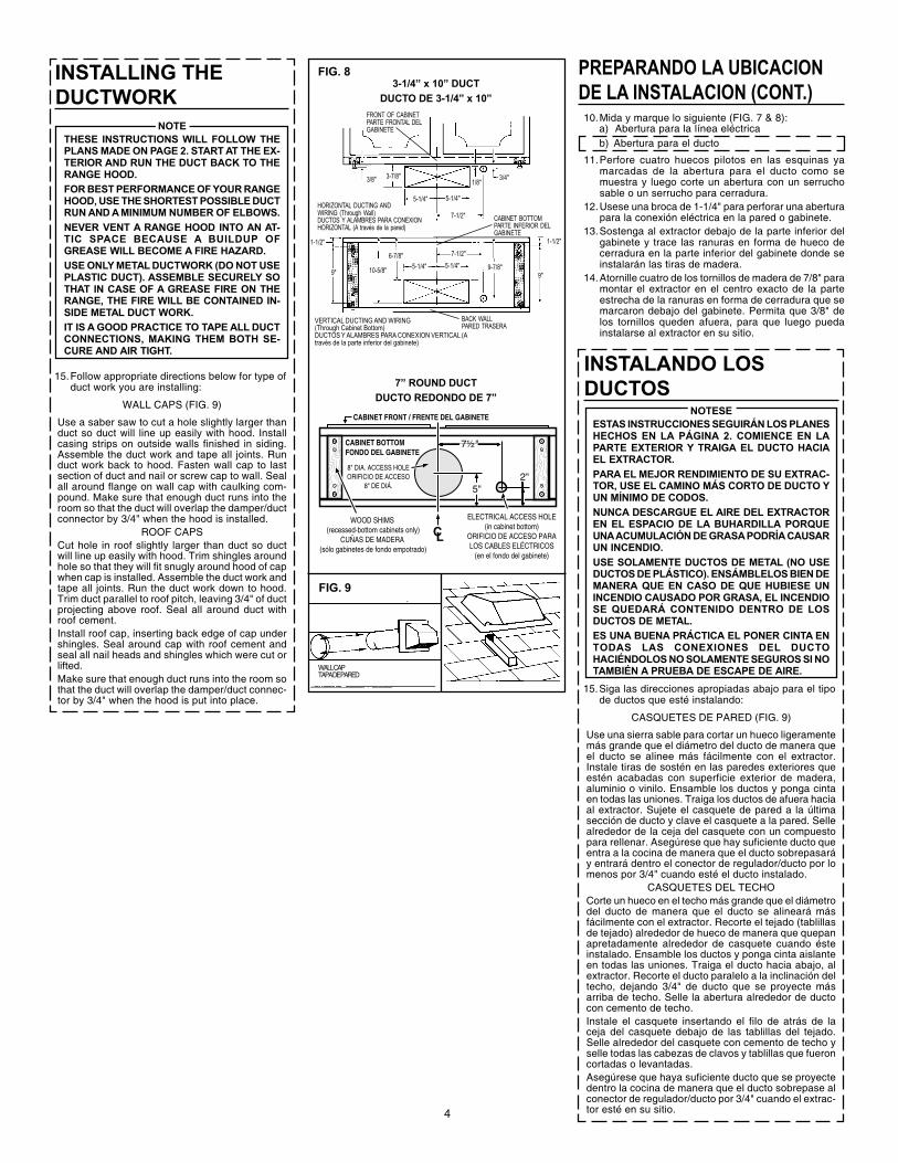
CABINET FRONT / FRENTE DEL GABINETE
CABINET BOTTOMFONDO DEL GABINETE
7½"
2"5"
WOOD SHIMS (recessed-bottom cabinets only)
CUÑAS DE MADERA (sólo gabinetes de fondo empotrado)
ELECTRICAL ACCESS HOLE (in cabinet bottom)
ORIFICIO DE ACCESO PARA LOS CABLES ELÉCTRICOS
(en el fondo del gabinete)
8" DIA. ACCESS HOLEORIFICIO DE ACCESO
8" DE DIÁ.
3-1/4” x 10” DUCTDUCTO DE 3-1/4” x 10”
7” ROUND DUCTDUCTO REDONDO DE 7”
PREPARANDO LA UBICACIONDE LA INSTALACION (CONT.)10.Mida y marque lo siguiente (FIG. 7 & 8):
a) Abertura para la línea eléctricab) Abertura para el ducto
11.Perfore cuatro huecos pilotos en las esquinas yamarcadas de la abertura para el ducto como semuestra y luego corte un abertura con un serruchosable o un serrucho para cerradura.
12.Usese una broca de 1-1/4" para perforar una aberturapara la conexión eléctrica en la pared o gabinete.
13.Sostenga al extractor debajo de la parte inferior delgabinete y trace las ranuras en forma de hueco decerradura en la parte inferior del gabinete donde seinstalarán las tiras de madera.
14.Atornille cuatro de los tornillos de madera de 7/8" paramontar el extractor en el centro exacto de la parteestrecha de la ranuras en forma de cerradura que semarcaron debajo del gabinete. Permita que 3/8" delos tornillos queden afuera, para que luego puedainstalarse al extractor en su sitio.
USE AND CARESWITCHESThe fan and light are each controlled by a rockerswitch. The light switch has two positions, “ON” and“OFF”. The fan switch has three positions - “HIGH”,“LOW” and “OFF”. ( “OFF” is the middle position.)CLEANINGFinish Keep your range hood clean using a mild de-tergent suitable for painted surfaces.Aluminum Filters should be cleaned frequently witha detergent solution to avoid grease build up. Theyare also dishwasher safe.
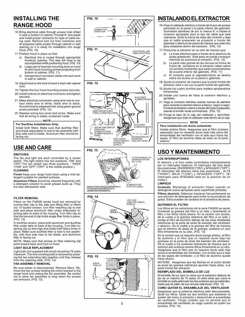
INSTALLING THERANGE HOOD16.Bring electrical cable through access hole drilled
in wall or bottom of cabinet. Provide 6" wire leadsand install proper connector for type of cable be-ing used. Remove lock nut from connector andlet prepared cable project through cabinet or wallopening so it is ready for installation into rangehood. (FIG. 10)
17.Position hood in place so that:a) Electrical line is routed through appropriate
knockout opening. This step will have to beaccomplished while positioning hood. (FIG. 13)
b) Large part of keyhole mounting slots on hoodfit onto hood mounting screws projecting frombottom of cabinet. (FIG. 11)
c) Damper/duct connector slides into duct workin wall or cabinet.
18.Adjust hood so the front of hood is flush with cabinetfront.
19.Tighten the four hood mounting screws securely.20. Install locknut on electrical connector and tighten
securely.21.Make electrical connection using wire nuts to con-
nect white wire to white, black wire to black.Ground hood to prepared hole using green groundscrew provided. (FIG. 12)
22. Replace wiring box cover and screw. Make surethat all wiring is safely contained inside.
NOTEFor Ductfree Installations Only:Install both filters. Make sure that ductfree filter(purchase separately) is next to fan assembly withblue side next to blade. Aluminum filter should befacing out.
FILTER REMOVALFilters on the F40000 series hood are removed byturning filter clip to the side and lifting filter or filtersout. In ducted version, turn filter retaining clip to oneside and place aluminum filter under embossed re-taining tabs on back of fan housing. Turn filter clip sothat the low end of clip holds single filter firmly in place.(FIG. 13)In ductfree version, place both aluminum and ductfreefilter under tabs on back of fan housing. Turn filter re-taining clip so that high end holds both filters firmly inplace. Make sure ductfree filter is next to fan assem-bly, with blue side next to fan blade, and aluminumfilter is facing out.NOTE: Make sure that arrows on filter retaining clippoint toward back and front of hood.LIGHT BULB REPLACEMENTLight bulb (not supplied with hood) should be 75 wattsmaximum. The lens covering bulb is removed by press-ing the two extending tabs together until they releasefrom the retaining slots. (FIG. 14)FAN ASSEMBLY REMOVALBe sure power is disconnected. Remove filters. Re-move the two screws holding the motor bracket to therange hood and unplug the fan assembly. Be carefulnot to allow fan assembly to drop when the screwsare removed. (FIG. 15).
5
CONNECTORCONECTOR
FIG. 12
FIG. 13
NON-DUCTED FILTER (SOLD SEPARATELY)FILTRO QUE NO REQUIERE DUCTO(VENDIDO SEPARADAMENTE)
ALUMINUM FILTERFILTRO DE ALUMINIO
FILTER RETAINING CLIPGRAMPA RETENTORADEL FILTRO
FIG. 14LIGHT LENSVIDRIO QUE CUBRE ELBOMBILLO
SOCKETBOQUILLA
FIG. 15
SCREWSTORNILLOS
ELECTRICAL LINELINEA ELECTRICA
FIG. 11
FIG. 10 INSTALANDO EL EXTRACTOR16.Pase el cableado eléctrico a través del hueco de acceso
perforado en la pared o la parte inferior del gabinete.Suministre alambres de por lo menos 6" e instale elconector apropiado para el tipo de cable que estáusándose. Quite la tuerca de traba del conector y dejeque el cable preparado se proyecte a través delgabinete o abertura de pared de manera que esté listopara instalarse dentro del extractor. (FIG. 10)
17.Posicione al extractor en su sitio de manera que:a) La línea eléctrica pase a través de la abertura de
quitar golpeando. Este paso se puede conseguirmientras se posiciona el extractor. (FIG. 13)
b) La parte más grande de las ranuras en forma dehueco de cerradura en el extractor caben sobrelos tornillos montantes que están proyectándosede la parte inferior del gabinete. (FIG. 11)
c) El conector para el regulador/ducto se deslizasobre los ductos en la pared o gabinete.
18.Ajuste el extractor de manera que la parte frontal delextractor esté a ras con la parte frontal del gabinete.
19.Ajuste los cuatro tornillos para madera apretándolosfirmemente.
20. Instale una tuerca de traba al conector eléctrico yapriételo.
21.Haga la conexión eléctrica usando tuercas de alambrepara conectar el alambre blanco a blanco, negro a negro.Conecte el extractor a tierra a través del hueco preparado,usando el tornillo verde suministrado. (FIG. 12)
22.Ponga la tapa de la caja del cableado y atorníllela.Asegúrese que todo el cableado esté dentro de la caja.
NOTAPara instalación sin ducto solamente:Instale ambos filtros. Asegúrese que el filtro (compraseparado) que no necesita ducto esté más cerca delemsamblaje del ventilador con el lado azul hacia lasaspas. El filtro de aluminio debe de estar en la parteexterior.
USO Y MANTENIMIENTOLOS INTERRUPTORESEl abanico y el foco están controlados individualmentepor un interruptor balancín. El interruptor del foco tienedos posiciones, ENCENDIDO (“ON”) y APAGADO (“OFF”).El interruptor del abanico tiene tres posiciones - ALTA(“HIGH”), BAJA (“LOW”) y APAGADO (“OFF”). (Elinterruptor para APAGADO está en la posición de enmedio.)LIMPIEZAAcabado. Mantenga el extractor limpio usando undetergente suave apropiado para superficies pintadas.Filtros aluminio. Deberían limpiarse frecuentemente enuna solución de detergente para evitar la acumulación degrasa. Estos pueden ser lavados en la lavadora de platos.
QUITANDO EL FILTROLos filtros en los extractores de la serie F40000 se sacanmoviendo la grampa del filtro a un lado y levantando elfiltro o los filtros hacia afuera. En la versión con ductos,dé la vuelta a la grampa retentora del filtro a un lado yponga el filtro de aluminio debajo de las uñas resaltadasretentoras en la parte de atrás de bastidor del ventiladoro abanico. De la vuelta a la grampa del filtro de maneraque el extremo de abajo de la grampa, sostiene un solofiltro firmemente en su sitio. (FIG. 13)En la versión que no requiere ducto ponga ambos, el filtrode aluminio y el filtro que no requiere ducto bajo lasgrampas en la parte de atrás del bastidor del ventilador.Dé la vuelta a los sostenes retentores de manera que elextremo alto sostiene ambos filtros firmemente en su sitio.Asegúrese que el filtro que no requiere ducto esté máscerca al ensamblaje del ventilador, con el lado azul a ladode las aspas del ventilador, y el filtro de aluminio quedehacia afuera.NOTESE: Asegúrese que las flechas en el punto dondese pone las grampa retentoras apunten hacia atrás, a laparte frontal del extractor.REEMPLAZO DEL BOMBILLO DE LUZEl bombillo de luz (que no viene con el extractor) debería deser de un máximo de 75 vatios. El vidrio lente que cubre elbombillo se quita pellizcado los dos sostenes que se extienden,hasta que se salen de sus ranuras retentoras. (FIG. 14)COMO QUITAR EL ENSAMBLAJE DEL VENTILADORAsegúrese que la potencia eléctrica esté desconectada.Quite los filtros. Quite los dos tornillos que sostienen elsostén del motor al extractor y desenchufe el ensamblajede ventilador. Tenga cuidado que no permita que elensamblaje del ventilador se caiga cuando se quiten lostornillos. (FIG. 15)
BLACK WIRESALAMBRES NEGROS
GROUNDING BRACKETSOSTEN PARACONECTAR A TIERRA
STAR LOCKNUTTUERCA TRABANTEEN FORMA DEESTRELLA
GREEN GROUND SCREWTORNILLO VERDE PARA TIERRA
GROUND WIRE (BARE ORGREEN WIRE)ALAMBRE DE TIERRA(ALAMBRE DESNUDO OVERDE)
WHITE WIRESALAMBRES BLANCOS

COMO EVITAR QUE OCURRA UN INCENDIODEBIDO A LA GRASA QUE SE ACUMULA EN UNEXTRACTOR COMUN• Su extractor proporciona una barrera protectora
entre la superficie para cocinar y los gabinetes.• Mantenga el abanico, los filtros y las superficies
donde se acumula la grasa LIMPIAS conforme alas instrucciones.
• ENCIENDA siempre el extractor cuando estécocinando a fuego alto para mantener el area paracocinar y el extractor limpios.
• Utilice las hornillas de fuego alto solamente cuandosea necesario.
• No deje las hornillas de la estufa sin atencióncuando esté cocinando. El vapor o el aceiteque salpique puede ocasionar un incendioo acumulación de humo.
• Siempre utilice los utensilios del tamaño adecuado.• Si está preparando alimentos flameados, como las
Cerezas a la Jubilee, ENCIENDA siempre el ex-tractor en ALTO para evitar que el calor puedacausar algún daño o un incendio.
COMO EXTINGUIR UN INCENDIO EN UN EXTRAC-TOR COMUN• No levante nunca una sartén que esté en llamas.
Si se le cae, las llamas se pueden extenderrapidamente.
• ¡NO UTILICE AGUA PARA APAGARLO! Puedeocasionar una explosión de vapor. Las toallas decocina mojadas también son peligrosas.
• Ahogue las llamas con una tapa ajustada o unacharola.
• Las llamas provocadas por la grasa también sepueden apagar con bicarbonato de sodio o unextinguidor químico.
• Apague las hornil las - si puede hacerlo sinquemarse.
HOW TO AVOID A COMMON RANGE-TOPGREASE FIRE• Your range hood provides a protective barrier
between the cooking surface and the cabinets.• Keep fan, filters and grease laden surfaces
CLEAN according to instructions.• Always turn hood ON when cooking at high heat
to keep the cooking area and the hood cooler.• Use high heat settings only when necessary.• Never leave cooking surface unattended. Boil-
over causes smoking and greasy spillovers thatmay ignite.
• Always use adequate-sized utensils.• If preparing flaming foods, such as Cherries Ju-
bilee, always turn hood ON to HIGH to preventa high heat situation which can cause damageor fire.
HOW TO EXTINGUISH A COMMON RANGE-TOPGREASE FIRE• Never pick up a flaming pan. If dropped, flames
can spread quickly.• DO NOT USE WATER! A violent steam explo-
sion may result. Wet dishcloths or towels arealso dangerous.
• Smother flames with a close fitting lid, cookiesheet or metal tray.
• Flaming grease can also be extinguished withbaking soda or a multi-purpose dry chemicalextinguisher.
• Turn off surface units - if you can do so withoutgetting burned.
6
GARANTIA BROAN LIMITADA POR UN AÑOBroan-NuTone garantiza al consumidor comprador original de sus productos que dichos productos careceránde defectos en materiales o en mano de obra por un período de un año a partir de la fecha original de compra.NO EXISTEN OTRAS GARANTIAS, EXPLICITAS O IMPLICITAS, INCLUYENDO, PERO NO LIMITADAS A,GARANTIAS IMPLICITAS DE COMERCIALIZACION O APTITUD PARA UN PROPOSITO PARTICULAR.Durante el período de un año, y a su propio criterio, Broan-NuTone reparará o reemplazará, sin costo algunocualquier producto o pieza que se encuentre defectuosa bajo condiciones normales de servicio y uso.ESTA GARANTIA NO SE APLICA A TUBOS Y ARRANCADORES DE LAMPARAS FLUORESCENTES. Estagarantía no cubre (a) mantenimiento y servicio normales o (b) cualquier producto o piezas que hayan sidoutilizadas de forma errónea, negligente, que hayan causado un accidente, o que hayan sido reparadas omantenidas inapropiadamente (por otras compañías que no sean Broan-NuTone), instalación defectuosa, oinstalación contraria a las instrucciones de instalación recomendadas.La duración de cualquier garantía implícita se limita a un período de un año como se especifica en la garantíaexpresa. Algunos estados no permiten limitaciones en cuanto al tiempo de expiración de una garantía implícita,por lo que la limitación antes mencionada puede no aplicarse a usted.LA OBLIGACION DE BROAN-NUTONE DE REPARAR O REEMPLAZAR, SIGUIENDO EL CRITERIO DE BROAN-NUTONE, DEBERA SER EL UNICO Y EXCLUSIVO RECURSO LEGAL DEL COMPRADOR BAJO ESTAGARANTIA. BROAN-NUTONE NO SERA RESPONSABLE POR DAÑOS INCIDENTALES, CONSIGUIENTES,O POR DAÑOS ESPECIALES QUE SURJAN A RAIZ DEL USO O DESEMPEÑO DEL PRODUCTO.Algunos estados no permiten la exclusión o limitación de daños incidentales o consiguientes, por lo que lalimitación antes mencionada puede no aplicarse a usted. Esta garantía le proporciona derechos legalesespecíficos, y usted puede también tener otros derechos, los cuales varían de estado a estado. Esta garantíareemplaza todas las garantías anteriores.Para calificar en la garantía de servicio, usted debe (a) notificar a Broan-NuTone al domicilio que se mencionaabajo o al teléfono:1-800-637-1453, (b) dar el número del modelo y la identificación de la pieza, y (c) describirla naturaleza de cualquier defecto en el producto o pieza. En el momento de solicitar servicio cubierto por lagarantía, usted debe de presentar evidencia de la fecha original de compra.
Broan-NuTone LLC926 West State Street,
Hartford, WI 53027 E.U.A.
BROAN-NUTONE ONE YEAR LIMITED WARRANTYBroan-NuTone warrants to the original consumer purchaser of its products that such products will befree from defects in materials or workmanship for a period of one year from the date of originalpurchase. THERE ARE NO OTHER WARRANTIES, EXPRESS OR IMPLIED, INCLUDING, BUTNOT LIMITED TO, IMPLIED WARRANTIES OF MERCHANTABILITY OR FITNESS FOR A PAR-TICULAR PURPOSE.During this one-year period, Broan-NuTone will, at its option, repair or replace, without charge, anyproduct or part which is found to be defective under normal use and service.THIS WARRANTY DOES NOT EXTEND TO FLUORESCENT LAMP STARTERS AND TUBES.This warranty does not cover (a) normal maintenance and service or (b) any products or parts whichhave been subject to misuse, negligence, accident, improper maintenance or repair (other than byBroan-NuTone), faulty installation or installation contrary to recommended installation instructions.The duration of an implied warranty is limited to the one-year period as specified for the expresswarranty. Some states do not allow limitation on how long an implied warranty lasts, so the abovelimitation may not apply to you.BROAN-NUTONE’S OBLIGATION TO REPAIR OR REPLACE, AT BROAN-NUTONE’S OPTION,SHALL BE THE PURCHASER’S SOLE AND EXCLUSIVE REMEDY UNDER THIS WARRANTY.BROAN-NUTONE SHALL NOT BE LIABLE FOR INCIDENTAL, CONSEQUENTIAL OR SPECIALDAMAGES ARISING OUT OF OR IN CONNECTION WITH PRODUCT USE OR PERFORMANCE.Some states do not allow the exclusion or limitation of incidental or consequential damages, so theabove limitation may not apply to you.This warranty gives you specific legal rights, and you may also have other rights, which vary fromstate to state. This warranty supersedes all prior warranties.To qualify for warranty service, you must (a) notify Broan-NuTone at the address stated below ortelephone: 1-800-637-1453, (b) give the model number and part identification and (c) describe thenature of any defect in the product or part. At the time of requesting warranty service, you mustpresent evidence of the original purchase date.
Broan-NuTone LLC926 West State Street,
Hartford, WI 53027

7
PARTES DE SERVICIOSERIE F40000 CAMPANA EXTRACTORA
SERVICE PARTSF40000 SERIES RANGE HOOD
KEY NO. PART NO.NO. CODIGO NO. PIEZ DESCRIPTION DESCRIPCION
1 98006621 Outlet Box Cover Cubierta de la caja de la toma de corriente2 99170245 #8 x 3/8 Sheet Metal Screw* Tornillos de metal para lámina #8 x 3/8*3 99270987 Bulb Holder with Wires Contenedor del bulbo con cableado4 99110437 Light Lens Cubierta protectora del foco5 97011217 Screw/Nut Kit (Includes 2 - #10-16 x .500 screws and Paquete de tornillos/tuercas (incluye 2 tornillos
2 - #10-16 sheet metal nuts) #10-16 x 0.500 y 2 tuercas de metal de lámina #10-16)6 99020272 Fan Blade Navajas del abanico7 99260428 #6-32 Locking Nuts* (2 Required) Tuercas #6-32* (se necesitan 2)8 98005568 Motor Mounting Bracket Soporte de montura del motor9 97012248 Motor Assembly (Includes Key Nos. 6, 7, and 8) Conjunto del motor (incluye piezas 6, 7, y 8)10 97006931 Aluminum Filter Filtro de aluminio
97007696 Non-Ducted Filter (purchase separately) Filtro que no requiere ducto (vendido separadamente)11 99420472 Filter Retainer Contenedor del filtro12 99150415 #8B x 1/4 Hex Head Sheet Metal Screws* (2 Req.) Tornillos de metal de cabeza hexagonal #8B x 1/4*
(se necesitan 2)13 98005221 Damper Flap Protección del regulador14 99100379 Damper Bushing Forro de metal del regulador15 97005544 Damper Assembly (Includes Key Nos. 13 and 14) Ensamblado del regulador (incluye piezas 13 y 14)16 97010709 Nameplate (Black) Rótulo (Negra)
99090881 Nameplate (White) Rótulo (Blanca)99091077 Nameplate (Biscuit) Rótulo (Beige)
17 97016970 2-Speed Motor Switch (Black) (Includes Key No. 18) Interruptor del motor de 2 velocidades (Negra) (incluye pieza 18)97016971 2-Speed Motor Switch (White) (Includes Key No. 18) Interruptor del motor de 2 velocidades (Blanca) (incluye pieza 18)97016973 2-Speed Motor Switch (Biscuit) (Includes Key No. 18) Interruptor del motor de 2 velocidades (Beige) (incluye pieza 18)
18 97016970 Light Switch (Black) (Includes Key No. 17) Interruptor del foco (Negra) (incluye pieza 17)97016971 Light Switch (White) (Includes Key No. 17) Interruptor del foco (Blanca) (incluye pieza 17)97016973 Light Switch (Biscuit) (Includes Key No. 17) Interruptor del foco (Beige) (incluye pieza 17)
19 97005678 Motor Receptacle with Wires Recipiente del motor con cableado20 99091022 Louver Cover (Black) Tapa de la rejillas (Negra)
99091020 Louver Cover (White) Tapa de la rejillas (Blanca)99091021 Louver Cover (Almond) Tapa de la rejillas (Almendra)99091027 Louver Cover (Biscuit) Tapa de la rejillas (Beige)
21 R680508 7” Round Duct Plate Placa para conducto redondo de 7”
Order service parts by “PART NO.” – NOT by “KEY NO.” Encargue piezas de servicio por “NO. PIEZA” – NO por “NO CODIGO”* Standard Hardware. May be purchased locally. * Piezas estándar. Se pueden comprar localmente.
45
65
378
10
17 18
1916
14
1315
12
20
1
29
11
21

Broan-NuTone LLC, 926 West State Street, Hartford, WI 53027 (1-800-637-1453) 99043016J