Embed Size (px)
Citation preview

CAN/CSA-B651-95Barrier-Free Design
A National Standard of Canada
Please Note: ∆ Refers to a formally approved revision dated June 1996
Copyright © Canadian Standards Association (1)— 1995All rights reserved. No part of this publication may bereproduced in any form, in an electronic retrieval systemor otherwise, without the prior permission of thepublisher.

Barrier-Free Design
September 1995 iii
Contents
Technical Committee on Barrier-Free Design
Preface
1. Scope
2. Reference Publications
3. General Requirements 3.1 Space Allowances 3.2 Controls and Operating Mechanisms 3.2.1 Floor Space 3.2.2 Height 3.2.3 Operation 3.2.4 Illumination 3.3 Ground and Floor Surfaces 3.3.1 General 3.3.2 Changes in Level 3.3.3 Carpets 3.3.4 Gratings 3.4 Protruding Objects 3.4.1 General 3.4.2 Detectable Objects Attached to a Wall 3.4.3 Freestanding Objects 3.4.4 Clear Width Maintenance 3.4.5 Headroom
4. Circulation 4.1 Accessible Routes, Paths, or Corridors 4.1.1 Width 4.1.2 Slope4.2 Doors4.2.1 Clear Opening 4.2.2 Double-Leaf Doorways 4.2.3 Manoeuvering Space at Doors 4.2.4 Two Doors in Series 4.2.5 Thresholds 4.2.6 Door Hardware 4.2.7 Door-Opening Force4.2.8 Power-Assisted Swinging Doors4.3 Ramps4.3.1 Running Slope and Length 4.3.2 Cross Slope4.3.3 Width4.3.4 Landings 4.3.5 Ramp Surfaces 4.3.6 Outdoor Conditions 4.3.7 Edge Protection

CAN/CSA-B651-95
iv September 1995
4.3.8 Ramp Handrails 4.4 Curb Ramps 4.4.1 Slope4.4.2 Width4.4.3 Surfaces 4.4.4 Flared Sides 4.4.5 Location at Pedestrian Crosswalks4.4.6 Islands4.5 Stairs 4.5.1 Treads and Risers4.5.2 Nosings4.5.3 Detectable Warning Surfaces4.5.4 Stair Handrails4.6 Handrails 4.7 Elevator Requirements 4.8 Elevating Devices 4.9 Areas of Refuge
5. Washroom Facilities 5.1 Washroom Identification 5.2 Toilet Stalls5.2.1 General 5.2.2 Toilet Stall Doors 5.3 Toilets5.3.1 General5.3.2 Toilet Location5.3.3 Toilet Flush Controls 5.3.4 Toilet Grab Bars 5.4 Lavatories5.4.1 General5.4.2 Faucets 5.4.3 Lavatory Clearance 5.5 Washroom Accessories 5.5.1 General5.5.2 Mirrors5.6 Individual Washrooms5.6.1 General 5.6.2 Equipment 5.7 Bathtubs5.7.1 Floor Space5.7.2 Grab Bars5.7.3 Controls 5.7.4 Shower Head5.7.5 Enclosures 5.8 Shower Stalls5.8.1 Roll-in Shower Stalls5.8.2 Shower Stalls with Seat 5.8.3 Shower Controls5.8.4 Shower Heads 5.8.5 Shower Enclosures

Barrier-Free Design
September 1995 v
5.8.6 Shower Floors 5.9 Grab Bars 5.9.1 Size and Spacing5.9.2 Structural Strength5.9.3 Safety5.10 Drinking Fountains5.10.1 Spouts 5.10.2 Controls5.10.3 Floor Space
6. Communications 6.1 Visual Alarms 6.2 Public Telephones 6.2.1 Protruding Parts 6.2.2 Controls 6.2.3 Cord Length 6.2.4 Illumination 6.2.5 Telephones for Persons in Wheelchairs 6.2.6 Telephones for Use by Persons Who Are Deaf or Hard of Hearing 6.2.7 Directional Signs 6.3 Assistive Listening Systems 6.4 Signage 6.4.1 Character Proportion 6.4.2 Contrast 6.4.3 Illumination6.4.4 Tactile Characters or Symbols6.4.5 Symbol of Access6.5 Detectable Warning Surfaces
7. Parking Spaces and Passenger Loading Zones 7.1 Circulation Routes7.2 Car Parking Spaces 7.3 Van Parking Spaces7.3.1 Size7.3.2 Height Clearance 7.4 Signs 7.4.1 Designated Stalls7.4.2 Vertical Signs 7.4.3 Symbol of Access7.5 Passenger Loading Zones 7.5.1 Size and Access 7.5.2 Vertical Clearance
8. Seating Spaces8.1 Seating at Tables and Counters 8.1.1 Clear Floor Space 8.1.2 Clear Knee Space8.2 Viewing Positions
9. Recreation Facilities 9.1 Benches 9.2 Picnic Tables

CAN/CSA-B651-95
vi September 1995
10. Residential Units 10.1 Basic Access 10.1.1 Circulation 10.1.2 Controls and Outlets 10.1.3 Windows 10.1.4 Visual Alarms 10.1.5 Bathrooms 10.1.6 Kitchens 10.1.7 Laundry Facilities10.1.8 Outdoor Living Areas10.2 Complete Access 10.2.1 General 10.2.2 Elevating Devices 10.2.3 Bathrooms 10.2.4 Kitchens 10.2.5 Miscellaneous Components
Appendices A—Slip Resistance of Floor FinishesB—AnthropometricsC—Elevator Requirements
Index

Barrier-Free Design
September 1995 vii
Technical Committee onBarrier-Free Design
D. Henning Public Works and Government ChairServices Canada, Ottawa, Ontario
A. Adams Barrier Free Design Centre,Toronto, Ontario
J. Beattie The Canadian Hearing Society,Toronto, Ontario
S. Brink Canadian Centre for Management Development,Ottawa, Ontario
W.E. Burningham Ontario Ministry of Housing,Toronto, Ontario
J.R. Champagne Ottawa, Ontario
J. Chu Bramalea Limited,Toronto, Ontario
K. Dissette BOMA,Toronto, Ontario
R.J. Dubiel American-Standard,Toronto, Ontario
P. Falta Montréal, Québec
R.A. Fern Parks Canada,Hull, Québec
G. Laneuville Ministère du Travail du Québec,Montréal, Québec
G. Maguire Stegweit and Maguire,Oakville, Ontario
H. Monk EEPPD,Ottawa, Ontario
T. Parker Canada Mortgage and Housing Corporation, Ottawa, Ontario

CAN/CSA-B651-95
viii September 1995
L. Pringle City of Etobicoke, Etobicoke, Ontario
J. Sanders The Canadian National Institute for the Blind, Ottawa, Ontario
R. Thompson British Columbia Ministry of Municipal Affairs,Victoria, British Columbia
J. Vasa School of Rehabilitation TherapyKingston, Ontario
Associate Members
E. Boyd Canadian Paraplegic Association, Ottawa, Ontario
B. Dion Betty Dion Enterprises,Ottawa, Ontario
G. Grey Public Works and Government Services Canada,Ottawa, Ontario
W. Hamilton The Canadian National Institute for the Blind, Ottawa, Ontario
A. Prost Department of the Secretary of State,Ottawa, Ontario
C. Stark Gloucester, Ontario
C. Zwierzchowski Public Works Canada,Ottawa, Ontario
T. Bartoffy Canadian Standards Association, AdministratorEtobicoke, Ontario

Barrier-Free Design
September 1995 ix
Preface
Individuals with disabilities shall be assured access to fundamental elements of daily life that aregenerally available in the community. Wherever possible the effects of an impairment or disability onan individual’s life shall not be determined by environmental factors.
(Principle 5 from the Prime Minister’s Declaration on the Decade of Disabled Persons.)
This is the second edition of CSA Standard CAN/CSA-B651, Barrier-Free Design. The first edition waspublished in 1990. The Standard contains requirements for making buildings and other facilities
accessible to persons with a wide range of physical and sensory disabilities. It was developed to fulfill anexpressed need for a national, technical standard covering a broad range of building and environmentalfacilities; a standard which could be referenced in whole or in part by a variety of adopting authorities. It must be understood by the user of this Standard that the requirements contained herein are minimumlevels. This Standard does not have the force of law unless mandated by legislation or called up in theregulations of the authority having jurisdiction. The user is advised to contact the local authority havingjurisdiction in this area in order to determine to what extent this Standard is referenced. The requirements result from a consensus of the Committee members who represent a broad spectrum ofinterests. The members were encouraged and aided by the public comments received as a result of the widedistribution of a draft at the public comment stage. The format allows for commentary and illustrative information to be distinctly included but clearly separatefrom the requirements of the Standard. The document is organized by facility type such as circulation orwashroom facilities. Clause 10, Residential Units, can be used independently from the remainder of theStandard. Readers are encouraged to read the Scope section before using the document. CSA hereby recognizes the financial assistance provided by Public Works and Government ServicesCanada, whose support helped make the development of this Standard possible. The Handbook of B.C.Building Code, Section 3.7 and the ANSI Standard A117.1 were used as base references in developing thefirst edition of this Standard. This Standard was approved by the CSA Technical Committee on Barrier-Free Design under the jurisdictionof the Steering Committee on Public Safety. It has been approved as a National Standard of Canada by theStandards Council of Canada.
September 1995
Notes:(1) Use of the singular does not exclude the plural (and vice versa) when the sense allows.(2) Although the intended primary application of this Standard is stated in its Scope, it is important to notethat it remains the responsibility of the users of the Standard to judge its suitability for their particularpurpose.(3) This publication was developed by consensus, which is defined by the CSA Regulations GoverningStandardization as “substantial agreement reached by concerned interests. Consensus includes an attemptto remove all objections and implies much more than the concept of a simple majority, but not necessarilyunanimity.” It is consistent with this definition that a member may be included in the Technical Committeelist and yet not be in full agreement with all clauses of the publication.

CAN/CSA-B651-95
x September 1995
(4) CSA Standards are subject to periodic review, and suggestions for their improvement will be referredto the appropriate committee.(5) All enquiries regarding this Standard, including requests for interpretation, should be addressed toCanadian Standards Association, Standards Development, 178 Rexdale Boulevard, Etobicoke, OntarioM9W 1R3. Requests for interpretation should(a) define the problem, making reference to the specific clause, and, where appropriate, include anillustrative sketch;(b) provide an explanation of circumstances surrounding the actual field condition; and(c) be phrased where possible to permit a specific “yes” or “no” answer. Interpretations are published in CSA’s periodical Info Update. For subscription details, write to CSA SalesPromotion, Info Update, at the address given above.

Barrier-Free Design
September 1995 1
CAN/CSA-B651-95Barrier-Free Design
1. Scope
1.1This Standard specifies how to make buildings and other facilities barrier-free and therefore accessibleand safely usable by persons with physical or sensory disabilities. The disabilities considered are:mobility impairments such as reliance on crutches or a wheelchair; reaching and manipulationdisabilities; hearing impairments; deafness; visual impairment and blindness.
Commentary: Some people with very severe physical disabilities may have requirements beyond the leveldescribed in this Standard.
1.2This Standard describes technical requirements which can be applied to the design and construction ofnew facilities or modifications to existing facilities. This Standard does not describe the application oftechnical requirements. The extent to which these requirements will be applied is the responsibility ofothers such as adopting authorities or specifiers.
1.3The Standard contains minimum requirements based on adult dimensions. Dimensions are given in SI(metric) units (typically in millimetres) and, where converted from Imperial units, they have beenrounded off with respect for critical dimensions.
Commentary: When designing for specific individuals, their particular abilities and preferences should be takeninto account. For example, some people prefer to transfer to or from a wheelchair towards their preferred sidewhen using toilet facilities. If a facility is primarily to serve children, dimensions and other provisions should be adjusted to make themsuitable for children.
1.4Commentaries and diagrams are included for explanatory and illustrative purposes only and are not amandatory part of the Standard. They are shown in a different colour to distinguish them fromrequirements. All dimensions on figures are in millimetres. Grab bar dimensions are measured to thecentreline.

CAN/CSA-B651-95
2 September 1995
2. Reference Publication
2.1
CSA StandardsCAN/CSA-B44-94,Safety Code for Elevators;
CAN/CSA-B355-94,Lifts for Persons with Physical Disabilities;
CAN/CSA-B613-M87,Elevating Devices for the Handicapped in Private Residences;
CAN3-T515-M85 (R1992),Requirements for Handset Telephones Intended for Use by the Hard of Hearing;
CAN/CSA-Z323.4.2-M86,Wheelchairs—Determination of Overall Dimensions, Mass, and Turning Space;
CAN/CSA-Z323.4.3-M89,Wheelchairs—Determination of Static Stability;
CAN/CSA-Z323.4.4-M89,Wheelchairs—Determination of Brake Effectiveness;
CAN/CSA-Z323.4.6-M89,Wheelchairs—Determination of Maximum Speed, Acceleration, and Retardation of Electric Wheelchairs;
CAN/CSA-Z323.4.7-M89,Wheelchairs—Determination of Obstacle-Climbing Ability of Electric Wheelchairs.
British StandardsBS5395 Part 1:1977,Code of Practice for the Design of Straight Stairs.
3. General Requirements
3.1 Space AllowancesThe minimum clear floor or ground area required to accommodate a single, stationary wheelchair andoccupant shall be 750 x 1200 mm.
Commentary: Figure 1 illustrates the minimum clear floor area for a person in a typical wheelchair. There is avariety of wheelchair sizes, some of which may require an area larger than that shown in this document. Wherepossible, additional area should be provided to facilitate use by persons who rely on larger wheelchairs. The minimum clear floor or ground area for wheelchairs may be oriented for forward or parallel approach to anobject. Clear floor or ground area for wheelchairs may be part of the knee space where it is provided. Figure 2 shows the area required for a wheelchair to turn. For additional anthropometric and wheelchairinformation, see Appendix B.

Barrier-Free Design
June 1996(Replaces p. 3, September 1995) 3
750 min.
1200
min
.
1500 min.
Commentary: A 1200 x 1200 mm area would allow access for both forward and side approach.
Figure 1Minimum Clear Floor Area
Figure 2Minimum Clear Turning Space at Toe Level for a
Wheelchair to Turn 180º
�
3.2 Controls and Operating Mechanisms
3.2.1 Floor SpaceA clear, level floor area at least 750 x 1200 mm shall be provided at controls and operating mechanismssuch as dispensers and receptacles.

CAN/CSA-B651-95
June 19964 (Replaces p. 4, September 1995)
Switch Coinslot
Receptacle
Changereturn
1200
max
.40
0m
in.
Figure 3Height of Controls and Operating Mechanisms
Commentary: Automatic controls such as infrared and other electronic devices would facilitate use by persons with severely limiting disabilities. Operation with one hand is an important requirement for many persons, including amputees, persons who need one hand to steady themselves with a cane, or even persons carrying packages. The requIrement does not preclude several operations, one after the other. The kind of situation to be avoided, for example, is a door lock which must be turned with one hand while the handle is simultaneously turned with the other hand in order to open a door.
SNACKS
3.2.2 HeightThe operable parts of controls and operating mechanisms, such as dispensers and receptacles, shall belocated between 400 and 1200 mm from the floor (Figure 3).
3.2.3 OperationControls and operating mechanisms shall be operable(a) with one hand;(b) without tight grasping, pinching, or twisting of the wrist; and(c) with a force less than 22 N.
Commentary: The colour of controls and operating mechanisms should contrast with their backgrounds.
3.2.4 IlluminationControls and operating mechanisms shall be capable of being illuminated to at least a level of 100 lx.

Barrier-Free Design
June 1996(Replaces p. 5, September 1995) 5
3.3 Ground and Floor Surfaces
3.3.1 GeneralGround and floor surfaces shall be stable, firm, and slip resistant.
Commentary: Additional information on the slip resistance of various floor surfaces is provided in Appendix A. Exterior walkways should have a firm surface such as asphalt, concrete, pavers, well-compacted crushedstone, or lumber with the planks across the direction of travel. Irregular surfaces such as cobblestone and large exposed aggregate paving make walking or wheeling difficultfor persons with mobility impairments. Highly reflective surfaces can result in glare, which is a problem for many persons with visual impairments.
3.3.2 Changes in LevelChanges in level, except for elevators, shall conform to Table 1. (See Clause E2.1 of Appendix C forelevator requirements.)
Table 1Changes in Level
Vertical rise, mm Edge treatment
0 to 6 may be vertical
6.1 to 13 bevel, maximum slope 1:2
Over 13 treat as ramp or curb ramp(see Clauses 4.3 and 4.4)
3.3.3 CarpetsCarpets or carpet tile shall(a) be securely fixed;(b) have a firm cushion, pad, or backing, where used;(c) have a level loop, textured loop, level cut pile, or level cut/uncut pile texture with a maximum padand pile height of 13 mm; and(d) have exposed edges fastened to floor surfaces with trim conforming to Table 1.
3.3.4 GratingsGratings located in walking surfaces shall(a) have spaces not greater than 13 mm wide in one direction; and(b) be placed so that the long dimension is across the dominant direction of travel.
Commentary: Where possible, gratings should be located outside the accessible route.

CAN/CSA-B651-95
June 19966 (Replaces p. 6, September 1995)
Obstruction100max.
1980
min
.
Cane hits wall
Any
hei
ght
Obs
truc
tion
Clear Width >100
Cane hits obstruction
Obs
truc
tion
680
max
.
(b)(a)
Figure 4Limits of Protruding Objects
3.4 Protruding Objects
3.4.1 GeneralObjects protruding from walls with their leading edges between 680 and 1980 mm from the floor shallprotrude not more than 100 mm into pedestrian areas such as walkways, halls, corridors, passageways, oraisles (Figure 4(a)).
Commentary: The requirement to have an area free from obstruction is primarily to aid persons with visualimpairments as shown in Figures 4, 5, and 6. Examples of such obstructions are directional signs, treebranches, guy wires, public telephone enclosures, drinking fountains, and the underside of escalators orstairways. Potentially hazardous objects are noticed only if they are within the detection range of canes. Persons withvisual impairments, walking toward an object, can detect an overhang if its lowest surface is less than 680 mmfrom the floor, but when walking alongside projecting objects, they cannot detect overhangs. Where a person isusing a wall or an edge as a guide, a protrusion of not more than 100 mm is acceptable.
3.4.2 Detectable Objects Attached to a WallObjects with their leading edges below 680 mm from the floor may protrude any amount (Figure 4(b)).
�
Barrier-Free Design
September 1995 7
Sign
Cane hits post
1980
min
.
300max.
680
min
.
Cane hits post68
0m
ax.
(b)(a)
If greaterthan 300
Figure 5Freestanding Objects Mounted on Posts
SIGN
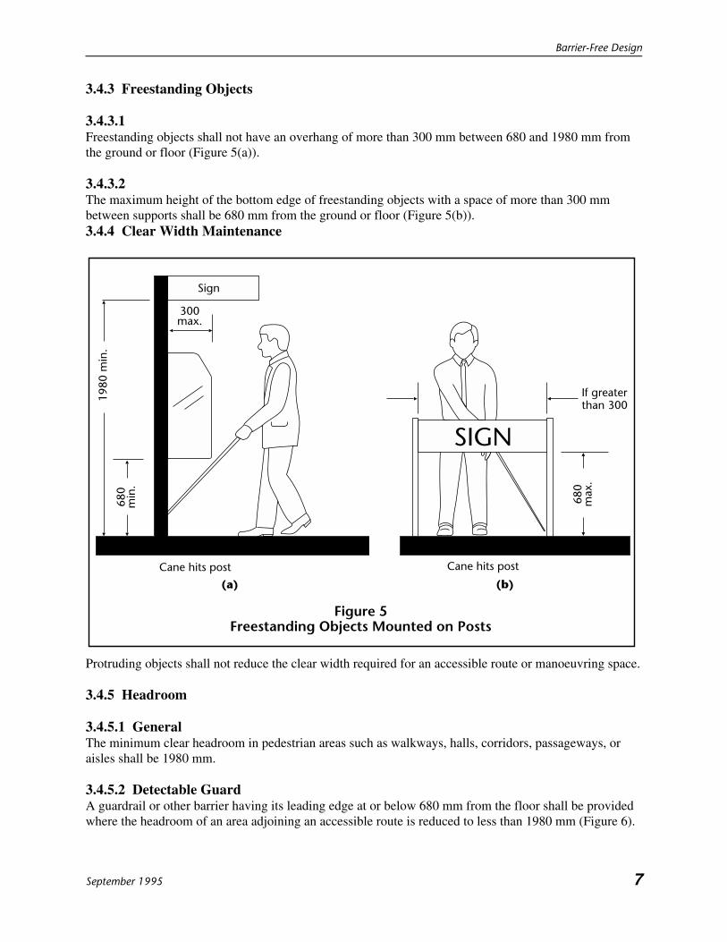
3.4.3 Freestanding Objects
3.4.3.1Freestanding objects shall not have an overhang of more than 300 mm between 680 and 1980 mm fromthe ground or floor (Figure 5(a)).
3.4.3.2The maximum height of the bottom edge of freestanding objects with a space of more than 300 mmbetween supports shall be 680 mm from the ground or floor (Figure 5(b)).3.4.4 Clear Width Maintenance
Protruding objects shall not reduce the clear width required for an accessible route or manoeuvring space.
3.4.5 Headroom
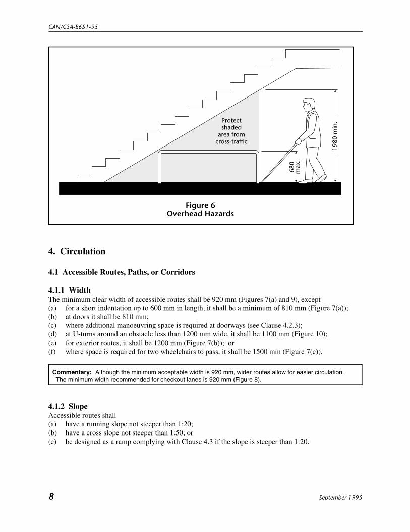
3.4.5.1 GeneralThe minimum clear headroom in pedestrian areas such as walkways, halls, corridors, passageways, oraisles shall be 1980 mm.
3.4.5.2 Detectable GuardA guardrail or other barrier having its leading edge at or below 680 mm from the floor shall be providedwhere the headroom of an area adjoining an accessible route is reduced to less than 1980 mm (Figure 6).
CAN/CSA-B651-95
8 September 1995
Protectshaded
area fromcross-traffic
680
max
.
1980
min
.
Figure 6Overhead Hazards
4. Circulation
4.1 Accessible Routes, Paths, or Corridors
4.1.1 WidthThe minimum clear width of accessible routes shall be 920 mm (Figures 7(a) and 9), except(a) for a short indentation up to 600 mm in length, it shall be a minimum of 810 mm (Figure 7(a));(b) at doors it shall be 810 mm;(c) where additional manoeuvring space is required at doorways (see Clause 4.2.3);(d) at U-turns around an obstacle less than 1200 mm wide, it shall be 1100 mm (Figure 10);(e) for exterior routes, it shall be 1200 mm (Figure 7(b)); or(f) where space is required for two wheelchairs to pass, it shall be 1500 mm (Figure 7(c)).
Commentary: Although the minimum acceptable width is 920 mm, wider routes allow for easier circulation. The minimum width recommended for checkout lanes is 920 mm (Figure 8).
4.1.2 SlopeAccessible routes shall(a) have a running slope not steeper than 1:20;(b) have a cross slope not steeper than 1:50; or(c) be designed as a ramp complying with Clause 4.3 if the slope is steeper than 1:20.

Barrier-Free Design
September 1995 9
Figure 7Width of Accessible Routes
1500 min.
(c)
810 min.
(a)
920 min.
600
max
.
1200 min.
(b)
Commentary: Long paths of travel should be avoided, and resting areas should be provided at frequent intervals (approximately 30 m). Where possible, exterior walkways should be protected from the elements.

CAN/CSA-B651-95
10 September 1995
920 min.
Checkout lane Counter
Figure 8Width of Accessible Checkout Lanes
920
min
.
920 min.920 min.
Obstacle
Greaterthan 1200
Figure 9Width of Accessible Route for a 90º Wheelchair
Turn, and a Turn Around an Obstacle

Barrier-Free Design
September 1995 11
1100 min.
Obstacle11
00 m
in.
1100 min.1200or less
Figure 10Width of Accessible Route for a Turn Around an
Obstacle That is Less Than 1200 mm Wide
4.2 Doors
4.2.1 Clear OpeningThe minimum clear opening of doorways shall be 810 mm measured between the face of the door and thestop with the door open 90� (Figure 11(a)).
Commentary: In existing buildings, swing-clear hinges can be used to increase the clear opening withoutchanging the frame (Figure 11(b)). Panic hardware that does not interfere with passage through a doorway is available and should be usedwherever possible.

CAN/CSA-B651-95
12 September 1995
Face ofstop
810 min.
Standardhinges
Face ofdoor
Face ofstop
810 min.
Swing-clearhinges
Face ofstop
810 min.
Standardhinges
Panicbar
(b)(a)
(c)
Face ofdoor
Figure 11Clear Opening of Doorway
4.2.2 Double-Leaf DoorwaysIf doorways have two independently operated door leaves, at least one active leaf shall comply withClauses 4.2.1 and 4.2.3.
4.2.3 Manoeuvring Space at DoorsDoorways shall have wheelchair manoeuvring space on both sides of the door, and a clear space besidethe latch as described in Table 2, except where access is only required from one side, such as to a closet(Figure 12.)

Barrier-Free Design
June 1996(Replaces p. 13, September 1995) 13
Table 2Manoeuvring Space at Doors, mm
Context
Floor space required
Depth WidthSpace besidelatch
Side hinged doorFront approach (Figure 12 (a))
Pull side 1500 1500 600Push side 1200 1200 300
Latch side approach (Figure 12 (b))Pull side 1200 1500 600Push side 1050 1500 600
Hinge side approach (Figure 12(c))Pull side 1500 1500 6000Push side 1050 1350 450
Sliding doorFront approach 1200 900 50Side approach 1050 1350 540
Commentary: Where a door leads to a ramp landing, additional space may be required (Clause 4.3.3).

CAN/CSA-B651-95
June 199614 (Replaces p. 14, September 1995)
1500min.
Pull Side
600min.
besidelatch
1500
min
.12
00m
in. 300
min.besidelatch
1200min.
(a) Front approach at hinged door
Figure 12Minimum Doorway Manoeuvring Space
Push Side
�

Barrier-Free Design
June 1996(Replaces p. 15, September 1995) 15
1500 min.
Pull Side
600min.beside latch
1050
min
.
Push Side
1200
min
.
1500 min.
1500 min.
Pull Side
600min.
besidelatch
1050
min
.
Push Side
1500
min
.
1350 min.
450min.
besidelatch
540min.
beside latch
1200
min
.
50 min. besidelatch
1050
min
.
1350 min.
(b) Latch side approach at hinged door
Figure 12 (Concluded)
(c) Hinge side approach at hinged door
(d) Front and side approach at sliding door
900 min.
�

CAN/CSA-B651-95
June 199616 (Replaces p. 16, September 1995)
1500 min. 1200 min. Doorwidth 1200 min.
minimum clear area
600
min
.1500
min
.
1200
min
.
600
min
.
300min.
1500 min.
1200 min.
1500
min
.
1200
min
.
300min.
1200
min
.
600min.
300min.
1200 min.
(b)
(a)
Figure 13Manoeuvring Space at Doors in Series
4.2.4 Two Doors in SeriesThe minimum space between two hinged or pivoted doors in series shall be 1200 mm plus the width ofany door swinging into the space (Figure 13).

Barrier-Free Design
September 1995 17
4.2.5 ThresholdsThresholds shall(a) be not more than 13 mm high;(b) at exterior sliding doors be not more than 19 mm high; and(c) where over 6 mm high, be bevelled at a maximum slope of 1:2.
Commentary: Where possible, thresholds should be avoided. They are a hazard to ambulant persons withdisabilities and a particular inconvenience to persons in wheelchairs.
4.2.6 Door Hardware
4.2.6.1 GeneralOperating devices such as handles, pulls, latches, and locks shall(a) be operable by one hand; (b) not require fine finger control, tight grasping, pinching, or twisting of the wrist to operate; and(c) be mounted between 400 and 1200 mm from the floor.
Commentary: Panic hardware that does not interfere with passage through a doorway is available and shouldbe used where possible. Knob handles do not provide for an adequate grip by persons with impaired hand functions. Lever handlesshould be used on latched doors. “U” shaped door handles (Figure 14) reduce the risk of catching clothing on orinjury from the exposed lever end. Push-pull mechanisms which do not require grasping are also easy to use. Kickplates 250 mm high on doors should be considered in high use areas to protect the push side of doors fromdamage caused by wheelchair footrests and to make it easier for persons in wheelchairs to open doors. If transparent glazing is incorporated in a door, it should extend low enough (900 to 1000 mm above the floor)to permit a person in a wheelchair to see and be seen (Figure 15). Door hardware should contrast with the colour of its background.
4.2.6.2 Sliding DoorsOperating hardware shall be exposed and usable from both sides when sliding doors are fully open.
Commentary: If the door retracts fully into a wall pocket, an accessible handle is required on the exposed edgeof the door.

CAN/CSA-B651-95
18 September 1995
Figure 14Handles
Leverhandles
Push platedoor pull
Knobhandles
Recommended Not recommended
4.2.6.3 Door ClosersThe s weep period of door closers shall be adjusted so that from an open position of 90º, thedoor will take not less than 3 s to move to a semiclosed position of approximately 12º.
Commentary: In some circumstances, closers with a delay feature that keeps the door open for severalseconds before it begins to close might be desirable. However, closers with this feature have limited back-check, a feature of a normal door closer where resistance to opening increases as the door reaches the full arcof swing. Doors equipped with this type of closer are therefore more susceptible to damage should the door beopened with too much force or should someone try to force it closed, thinking the closer has failed to operate.Delayed action closers are not recommended for occupancies such as schools.
4.2.7 Door-Opening ForceThe maximum force for pushing or pulling open a door shall be(a) 38 N for exterior hinged doors;(b) 22 N for interior hinged doors; and(c) 22 N for sliding or folding doors.
Commentary: These forces do not apply to the force required to retract latch bolts or disengage other devicesthat may hold the door in a closed position.
4.2.8 Power-Assisted Swinging DoorsPower-assisted swinging doors shall(a) take not less than 3 s to move from the closed to the fully open position; and(b) require a force of not more than 66 N to stop door movement.

Barrier-Free Design
September 1995 19
Figure 15Guards at Out-Swinging Automatic Doors
680
max
.
900-
1000
Commentary: At least one power-assisted or automatic door should be provided at the main entrance(s) to a building since exterior doors may not meet the force requirements of Clause 4.2.7 and still operate satisfactorily. Where doors swing into a path of travel, it is desirable to have guardrails provided at a cane-detectable height extending at right angles to the wall containing the door (Figure 15). Sliding automatic doors do not need guardrails for protection and are more convenient for persons in wheelchairs and visually impaired persons. Some large revolving doors can accommodate persons using wheelchairs or crutches. Turnstiles cannot be used by persons in wheelchairs and can be hazardous to ambulant persons who use crutches or canes. An accessible gate with a clear width of 810 mm should be provided beside a turnstile (Figure 16). Buttons or pads to open automatic doors must be well located, visible, and easily operable. The best location is determined by ensuring that the button or pad is(a) seen clearly before reaching the door;(b) at a height that can be operated from a standing or seated position; and(c) well clear of the door swing and any other fixtures. Visibility is enhanced by size, colour contrast, and lighting. Buttons or pads are easily operable when they (i) are operated by touch on any part of its surface; (ii) require little force to activate the door; and (iii) do not require finger movement but can be opened by touching with a closed hand or arm.

CAN/CSA-B651-95
20 September 1995
810 min.
Figure 16Access Beside Turnstiles
Inaccessible
Gate Turnstiles
4.3 Ramps
4.3.1 Running Slope and LengthThe slope shall not be steeper than 1:12 (8.33%) and the maximum horizontal length between landingsshall not exceed 9 m.
4.3.2 Cross SlopeThe maximum cross slope of ramp surfaces shall be 1:50.
Commentary: Ramps allow persons in wheelchairs to move from one level to another. However, manyambulatory persons with disabilities negotiate steps more easily and safely; thus, accessibility by both steps andramps is preferred. The slope should be as gentle as possible. The steeper the ramp, the more likely it is that persons inwheelchairs will require some form of assistance. Most persons can manage a slope of 1:15 to 1:20. Wherethere is a large change of elevation which requires multiple ramp and landing combinations, other solutionsshould be considered. A walkway with a slope gentler than 1:20 is not considered a ramp and may be any length. For curb ramps, see Clause 4.4
4.3.3 WidthThe minimum width of a ramp between handrails shall be 920 mm.
4.3.4 Landings
4.3.4.1Ramps shall have level landings at the top and bottom of each run and also where the ramp changesdirection (Figure 17).

Barrier-Free Design
September 1995 21
Figure 17Ramps and Landings
920 min.
Level landing
1500 min.Curbs or railsaround edgesof ramps andlandings
920 min.Level landing
1500 min.
1500 min.
1500 min.
920 min.
Level landing
1500 min.Curbs or railsaround edgesof ramps andlandings
1500 min.
600 min.
1500 min.
1840 min.
4.3.4.2The landing shall(a) be at least as wide as the widest ramp run leading to it;(b) have a length not less than 1500 mm; and(c) have a minimum size not less than 1500 1500 mm if served by a doorway.

CAN/CSA-B651-95
22 September 1995
Figure 18Edge Protection
75 m
in.
(a) (b) (c)
75 m
ax.
75 m
ax.
Commentary: Doorways at landings need sufficient manoeuvring space at the latch side of the door (Figure17).
4.3.5 Ramp SurfacesRamp and landing surfaces shall be slip resistant. (See Appendix A for additional guidance on slipresistance.)
4.3.6 Outdoor ConditionsOutdoor ramps and their approaches shall be designed so that water will not accumulate on walkingsurfaces.
Commentary: Consideration should be given to protecting ramps from rain, snow, and ice. Handrails should beprovided on both sides of the ramp.
4.3.7 Edge ProtectionRamps and landings not at grade or adjacent to a wall shall have edge protection such as a(a) curb with a minimum height of 75 mm (Figure 18(a));(b) raised barrier with its lower edge not more than 75 mm from the ramp or landing surface (Figure18(b)); or(c) rail with the bottom edge not more than 75 mm from the ramp or landing surface (Figure 18(c)).
4.3.8 Ramp HandrailsA ramp run with a rise greater than 150 mm shall have handrails which(a) are on both sides;(b) comply with Clause 4.6;(c) are continuous on the inside of switchback or dogleg ramps;

Barrier-Free Design
September 1995 23
Figure 19Handrail Extensions
300 min. 300 min.
300 min.Handrail returnsto floor
Handrail returnsto post
Handrail returnsto wall
Commentary: Handrail extensions at the top and bottom of ramps provide tactile cues for persons with visual impairments and provide support for persons who need help to negotiate ramps. Handrail extensions should not project into another path of travel, and handrails should return to the wall, floor, or post so as not to constitute a hazard to pedestrians. In order to provide a means for wheelchair users to pull themselves up the ramp using both handrails, the distance between handrails needs to be limited as in Clause 4.3.8 (f).
(d) when not continuous, extend horizontally at least 300 mm beyond the top and bottom of the rampand return to the wall, floor, or post (Figure 19);(e) have their tops between 800 and 920 mm from the ramp surface; and(f) have a distance between handrails of 920 to 1000 mm.
4.4 Curb Ramps
4.4.1 Slope
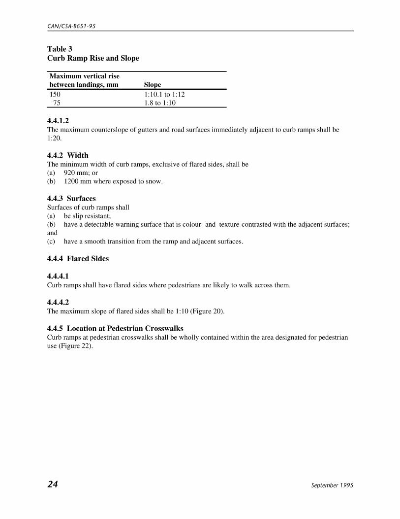
4.4.1.1The maximum running slope shall conform to Table 3, and the maximum horizontal length shall notexceed 2 m.
CAN/CSA-B651-95
24 September 1995
Table 3Curb Ramp Rise and Slope
Maximum vertical risebetween landings, mm Slope150 75
1:10.1 to 1:121.8 to 1:10
4.4.1.2The maximum counterslope of gutters and road surfaces immediately adjacent to curb ramps shall be1:20.
4.4.2 WidthThe minimum width of curb ramps, exclusive of flared sides, shall be(a) 920 mm; or(b) 1200 mm where exposed to snow.
4.4.3 SurfacesSurfaces of curb ramps shall(a) be slip resistant;(b) have a detectable warning surface that is colour- and texture-contrasted with the adjacent surfaces;and(c) have a smooth transition from the ramp and adjacent surfaces.
4.4.4 Flared Sides
4.4.4.1Curb ramps shall have flared sides where pedestrians are likely to walk across them.
4.4.4.2The maximum slope of flared sides shall be 1:10 (Figure 20).
4.4.5 Location at Pedestrian CrosswalksCurb ramps at pedestrian crosswalks shall be wholly contained within the area designated for pedestrianuse (Figure 22).

Barrier-Free Design
September 1995 25
Figure 21Curb Ramp with Returned Curb Sides
Figure 20Curb Ramp with Flared Sided
920 min.
Detectablewarningsurface
Flaredside
1:10 max.
Detectablewarningsurface
Planting or othernon-walking surface
Commentary: Curb ramps do not require handrails. Curb ramps should be as gradual as possible and should not project onto a road surface unless there is little or no vehicular traffic. It is desirable to have a level walking space 920 mm wide at the top of the ramp so pedestrians can avoid the ramp (Figure 20). Curb ramps with returned curbs are an alternative approach which can be used where pedestrians would not be expected to walk across the ramp (Figure 21). Curb ramps should be located where they will not be blocked by parked vehicles. Built-up curb ramps projecting into the roadway are not recommended because they are dangerous to users and obstructive to vehicles. A textured surface will assist in giving a secure foothold to ambulant persons. A detectable surface with a change in plane will assist persons with visual impairments.

CAN/CSA-B651-95
26 September 1995
Ramp withflared sides
Level crossingwith detectablewarning surfaces
at Island
Ramp withflared sides
Level crossingwith detectablewarning surfaces
at Island
(b)(a)
Commentary: Flared sides can be outside the pedestrian crosswalk.
Segment ofstraight curb
Figure 22Location of Curb Ramps at Pedestrian Crosswalks
4.4.6 Islands
4.4.6.1Raised islands in crossings shall(a) be cut through level with the street (Figure 22(a)); or (b) have curb ramps at both sides and a level area not less than 1200 mm long in the middle (Figure22(b)).
4.4.6.2Islands level with the street shall have within the area designated for pedestrian use detectable warningsurfaces that are(a) at least 900 mm long; and(b) of a texture and colour that contrasts with the surrounding walking surfaces.
4.5 Stairs
4.5.1 Treads and RisersA flight of stairs shall have(a) uniform riser heights and tread depths;(b) risers not more than 180 mm high;

Barrier-Free Design
September 1995 27
(c) treads not less than 280 mm deep, measured from riser to riser; and (d) no open risers (Figure 23(a)).
Commentary: Generally speaking, a longer tread is better for people with mobility impairments.
4.5.2 NosingsNosings shall(a) project not more than 38 mm;(b) have no abrupt undersides (Figure 23(b));(c) have a radius of curvature at the leading edge of the tread not more than 13 mm;(d) where projecting, be sloped to the riser at an angle greater than 60<F"Arial">°<F255> to thehorizontal (Figure 23(c));(d) where projecting, be sloped to the riser at an angle greater than 60° to the horizontal (Figure 23(c));(e) be illuminated to a level of at least 100 lx;(f) be slip resistant; and(g) have the horizontal face in a colour contrasting with the tread.
Commentary: The contrasting colour of the nosing is meant to ensure that the tread edge is clearly visible indescent.
4.5.3 Detectable Warning SurfacesDetectable warning surfaces shall(a) be provided at the top of the stairs and at landings;(b) extend the full width of the stair for a depth of at least 900 mm commencing one tread depth backfrom the stair (Figure 23(d)); and(c) consist of flooring material that is
(i) contrasting in colour with the surrounding flooring material; and(ii) of a different texture from the surrounding flooring material.

CAN/CSA-B651-95
28 September 1995
Figure 23Stair Detail
(a) (b)
Open risersnot permitted
Risers withoutrake back not
permitted
Tread depth280 min.
Nosing38 max.
Visualcontrast
180max.
Not lessthan 60º
(c)
(d)
900 min.
Detectablewarning surfaceat top of stairs
or landingDepth of
one thread
Riser
Thread
Visual contraston top of nosing
Horizontalnosing
Commentary: Stairs with open risers are hazardous to persons who need a solid riser to guide the foot up the riser to the next step, or who place canes or crutches against the riser of the next step. Where projecting nosings are used, they must not have sharp or abrupt angles that prevent the foot from sliding up the riser. It is important for stairs and ramps to have good illumination so that they can be easily seen. Strongly patterned carpets should not be used on stairs since they cause perceptual problems and obscure the definition of the tread edges.

Barrier-Free Design
September 1995 29
Figure 24Handrail in Stairway
300
Down
Up
580 min. extensionif handrail notcontinuous
Commentary: Many persons with disabilities rely upon handrails to maintain balance and prevent serious falls. Handrail extensions at the top and bottom of stairs provide tactile cues for persons with visual impairments, and a continuous handrail will assist them in negotiating stairs at changes in direction (Figure 24). Handrail extensions should not project into another path of travel, and handrails should return to the wall, floor, or post so as not to constitute a hazard (Figure 19). The extended handrail is useful for persons with physical limitations to steady themselves before climbing or descending the stairs. The "one-tread depth" extension at the bottom is to ensure that the horizontal handrail extension is at the same height as the handrail on the stair (Figures 25, 26, and 27).
4.5.4 Stair HandrailsHandrails for stairs shall(a) comply with Clause 4.6;(b) be installed on both sides (Figure 24);(c) be of uniform height, ranging between 800 and 920 mm from the stair nosing;(d) have a continuous inside handrail on switchback or dogleg stairs (Figure 25); and(e) where not continuous:
(i) extend at the top of the stairs parallel with the floor surface not less than 300 mm;(ii) continue at the bottom of the stairs to slope for a distance equal to the depth of the tread and
then extend parallel to the floor surface not less than 300 mm; and(iii) return to the wall, floor, or post (Figures 25, 26, 27).

CAN/CSA-B651-95
30 September 1995
Figure 25Continuous Handrail at Centre of Stair
Figure 26Handrail Extension at Bottom of Stair
Depth of onestair tread(280 min.)300
min.
800-
920
680
max
.

Barrier-Free Design
September 1995 31
Figure 27Handrail Extension at Top of Stair
300min.
680
max
.
800-
920
300min.
800-
920
Attached to wall
4.6 Handrails
4.6.1Handrails shall(a) have a circular section 30–40 mm in diameter or an alternative shape providing the same grippingsurface;(b) be free of any sharp or abrasive elements;(c) have continuous gripping surfaces, without interruption by newel posts, other constructionelements, or obstructions that can break a hand hold; and(d) have a clear space between the handrail and the wall of
(i) 35–45 mm; or(ii) at least 60 mm where the wall has a rough surface (Figure 28).
4.6.2A recess containing a handrail shall extend at least 450 mm above the top of the rail (Figure 29).

CAN/CSA-B651-95
32 September 1995
Figure 28Handrails
35-45 forsmooth wallsurfaces
60 min. forrough wallsurfaces
30-40
Figure 29Handrails in Recess
35-45 for smooth wall surfaces
450
min
.
60 min. forrough wall surfaces
35-40

Barrier-Free Design
September 1995 33
Figure 30Handrail Shapes
Commentary: Handrails are extremely important features and must be designed to be easy to grasp and to provide a firm and comfortable grip so the hand can slide along the rail without obstruction. A circular section with a diameter not more than 40 mm is the preferred shape so that the thumb and fingers can lock around the handrail. Wide or deep handrails which allow only a pinched grip are undesirable unless a proper hand-size grasping area is provided (Figure 30). Standard pipe sizes designated by the industry as 32 to 38 mm meet the requirements of Clause 4.6.1(a). The maximum clearance allowed is to provide for adequate gripping room and prevent injuries from arms slipping through the opening.
Acceptable Not acceptablePreferred
4.7 Elevator Requirements
4.7.1Elevators shall comply with Appendix E of CSA Standard CAN/CSA-B44.
Commentary: These requirements are reproduced in Appendix C of this Standard, along with additional recommendations. Where the depth of an elevator makes it difficult for a wheelchair user to turn around, providea mirror on the rear wall to allow the user to see the floor indicators.
CAN/CSA-B651-95
34 September 1995
4.8 Elevating Devices
4.8.1Elevating devices such as platform lifts shall comply with CSA Standard CAN/CSA-B355.
Commentary: Escalators are not considered a safe means of barrier-free travel.
4.9 Areas of Refuge
4.9.1Areas of refuge shall be(a) of a size that allows a minimum floor space of 850 x 1200 mm per nonambulatory occupant withno fewer than 2 such spaces;(b) separated from the floor area by a fire separation having a fire-resistance rating at least equal to thatrequired for an exit;(c) served by an exit or a firefighters’ elevator;(d) designated as an area of refuge for persons with disabilities on the building plans and in thebuilding; and(e) smoke protected in buildings of more than three storeys.

Barrier-Free Design
September 1995 35
Wheelchair space850 x 1200 min.
Figure 31Example of Refuge Area
Up
300
Commentary: An area of refuge is a space that facilitates a safe delay of egress, is protected from fire conditions developing in the floor area, and provides direct access to an exit or a firefighters' elevator. It provides a known place for firefighters to come get to persons unable to use stairs. A firefighters' elevator, referred to above, is an elevator system designed for use by firefighters and others with firefighter supervision. An exit through a fire wall may be considered equivalent to an area of refuge. Since areas of refuge provide temporary safety, it is important for the building management to have operating procedures in place which complement the building design features. The term "smoke protected" describes spaces that will contain not more than 1% by volume of contaminated air from the fire floor, during a 2 h period after the start of a fire, assuming an outdoor air temperature equal to the January design temperature on a 2½% basis. Signs along the normal path of egress should indicate the direction to the area of refuge. Nonambulatory occupants in areas of refuge should not obstruct egress. The door should not encroach on the space for wheelchairs. An area of refuge could be an enlarged landing in an exit stair (Figure 31). According to the National Building Code, Clause 3.3.1.7, a sprinklered building does not require areas of refuge.

CAN/CSA-B651-95
36 September 1995
Figure 32Example of a Washroom Layout
1500 min.
750min.
1500
min
.
1500 min.
1500 min.
1500
min
.12
00 m
in.
1200
min
.
300
max
.
450
min
.
600min.
Clearspace
Clearspace
Clearspace
460min.
460-480
300min.
Commentary: When entering and leaving washrooms, people using wheelchairs frequently encounter problems. Door arrangements and spacing must comply with Clause 4.2. Within the washroom, sufficient space is required to allow persons in wheelchairs to move freely to and from the various fixtures (Figure 32). For detailed dimensions for reaching/grasping refer to Appendix B.
480
max
.
5. Washroom Facilities
5.1 Washroom IdentificationSigns at washroom entrances shall comply with Clause 6.4.4.
5.2 Toilet Stalls
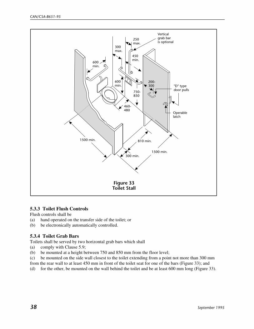
5.2.1 GeneralToilet stalls shall(a) have internal dimensions at least 1500 x 1500 mm (Figure 33);(b) have a toilet complying with Clause 5.3; and(c) be equipped with a coat hook mounted not more than 1400 mm from the floor on a side wall andprojecting not more than 40 mm from the wall.

Barrier-Free Design
September 1995 37
Commentary: The requirements do not preclude the addition of vertical grab bars. Flip-up grab bars can beused on the transfer side of the toilet. The toilet paper dispenser should be located so as not to interfere with the grab bar; under the grab bar, and infront of the toilet, is a convenient location.
5.2.2 Toilet Stall DoorsToilet stall doors shall(a) be capable of being locked from the inside by a device that is operable with one hand; does notrequire fine finger control, tight grasping, pinching, or twisting of the wrist; and requires a force not morethan 22 N to activate (eg, sliding bolt or lever);(b) provide a clear opening of at least 810 mm with the door in the open position;(c) swing outward, unless additional space is provided within the stall for the door swing;(d) be provided with a “D” type door pull, at least 140 mm long, on the inside of an outswinging door,located so that the centreline is between 200 and 300 mm from the hinged side of the door, at outsidedoor-handle height (Figure 33); and(e) be provided with a “D” type door pull at least 140 mm long, on the outside, near the latch side ofthe door.
5.3 Toilets
5.3.1 GeneralToilet fixtures shall have(a) the top of the seat between 400 and 460 mm from the floor (Figure 34);(b) no spring-activated seat;(c) a back support where there is no seat lid or tank; and(d) the tank top securely attached.
Commentary: A toilet seat lid is an inexpensive means of providing a back support.
5.3.2 Toilet LocationToilets shall be located between 460 and 480 mm from the centreline to the adjacent wall.be electronically controlled (Figure 36).
CAN/CSA-B651-95
38 September 1995
Figure 33Toilet Stall
600min.
300max.
250max.
Verticalgrab baris optional
450min.
600min.
750-850
"D" typedoor pulls
Operablelatch
460-480
1500 min.
810 min.
300 min.
1500 min.
200-300
5.3.3 Toilet Flush ControlsFlush controls shall be(a) hand operated on the transfer side of the toilet; or(b) be electronically automatically controlled.
5.3.4 Toilet Grab BarsToilets shall be served by two horizontal grab bars which shall(a) comply with Clause 5.9;(b) be mounted at a height between 750 and 850 mm from the floor level;(c) be mounted on the side wall closest to the toilet extending from a point not more than 300 mmfrom the rear wall to at least 450 mm in front of the toilet seat for one of the bars (Figure 33); and(d) for the other, be mounted on the wall behind the toilet and be at least 600 mm long (Figure 33).

Barrier-Free Design
September 1995 39
Figure 34Toilet Configuration
Commentary: Wall-hung toilets are preferred because they provide additional space at toe level. Preferences for toilet seat heights vary considerably. Higher seats may be an advantage to some ambulatory persons with disabilities but a disadvantage to persons in wheelchairs. Toilet seats 400 to 460 mm high offer a reasonable compromise. Thick seats and filler rings are available to adapt standard fixtures to these requirements. A back support reduces the chance of imbalance or injury caused by leaning against exposed valves or pipes. Flush valves and related plumbing can be located behind walls, beside the toilet, or behind the toilet seat. Flush controls for tank-type toilets have a standard mounting location on the left side of the tank (facing the tank). Tanks with controls mounted on the right side are often available by special order.
Grab bar300 min.
Backsupport
460-480
Flush valve ontransfer sideof toilet
750-
850
400-
460
Wall-mountedtoilet preferred
5.4 Lavatories
5.4.1 GeneralLavatories shall(a) be mounted so that the minimum distance between the centreline of the fixture and the side wall is460 mm;(b) have the top located between 820 and 860 mm from the floor;(c) have a knee space at least 750 mm wide, 200 mm deep, and 680 mm high with an additional toespace at least 750 mm wide, 230 mm deep, and 230 mm high;(d) have a minimum clear floor space 750 mm wide and 1200 mm deep of which a maximum of 480mm in depth may be under the lavatory; and(e) have hot water and drain pipes insulated if they abut the clearances noted above (Figure 35).

CAN/CSA-B651-95
40 September 1995
Figure 35Lavatory Clearances
(a) (b)
820-
860
720
min
.
680
min
.
230 min.toe clearance
230 min.toeclearance
200 min.kneeclearance
750min.
Clearspace
1200min.
460min.
230min.
820-
860
5.4.2 FaucetsFaucets and other controls shall(a) have handles of the lever type (not self-closing) operable with a closed fist; or(b) be electronically controlled (Figure 36).
5.4.3 Lavatory ClearanceThe front apron of a vanity shall have a minimum clearance 750 mm wide and 720 mm high (Figure 35).

Barrier-Free Design
September 1995 41
Figure 36Faucets
Infra-redfaucet
Recommended
Single leverhandle
Long leverhandles
Short lever handle
Not recommended
Push operated
Not recommendedunless very easyto push
Commentary: Clearance under a lavatory is required for wheelchair access. The trap should be offset to the rear to ensure that the knee-space is clear of obstructions. If this is not possible, the trap should be insulated to prevent heat injuries to the legs. Lavatories on pedestals are not recommended. It is desirable that lavatories be located in a vanity counter. However, if that is not possible, a shelf should be provided at counter level. Faucets with lever handles allow use with a minimum of pressure. Short levered handles are not recommended (Figure 36). Water temperatures at lavatories should be controlled to avoid the possibility of scalding. Faucets for lavatories, tubs, and showers should be colour-coded (red and blue) where possible.
5.5 Washroom Accessories
5.5.1 GeneralAt least one of each type of the washroom accessory provided shall have operable parts and controls lessthan 1200 mm from the floor (Figure 37).
5.5.2 MirrorsWhere mirrors are provided, at least one shall be mounted with its bottom edge not more than 1000 mmfrom the floor (Figure 37).

CAN/CSA-B651-95
42 September 1995
Figure 37Washroom Accessories
1000
max
.
1200
max
.
Commentary: Accessories such as towel dispensers and waste receptacles should not protrude into the path of travel but should be placed close to the accessible lavatory, to avoid having a person wheeling a chair with wet hands.
WASTE
5.6 Individual Washrooms
5.6.1 GeneralWhere a washroom containing one toilet and one lavatory (sometimes referred to as unisex, special, orunit washroom) is provided, it shall(a) have a floor area not less than 3.5 m2 with no dimension between opposite walls less than 1700mm;(b) have a clear space of at least 900 mm wide adjacent to the toilet (Figure 38);(c) have a toilet complying with Clause 5.3; and(d) have a lavatory complying with the requirements of Clause 5.4.
5.6.2 EquipmentWashrooms described in Clause 5.6.1 shall comply with the requirements of Clause 5.5 and shall beequipped with a(a) shelf or counter at least 200 x 400 mm;(b) coat hook mounted not more than 1400 mm from the floor on a side wall and projecting not morethan 40 mm from the wall; and(c) door which shall
(i) comply with Clause 5.2.2;(ii) be provided with spring-type or gravity hinges so that the door closes automatically; and(iii) be operable from the outside under emergency conditions.

Barrier-Free Design
September 1995 43
Figure 38Example Layout for an Individual Washroom
1500 min.
900 min.
750-850
Verticalgrab baris optional
1700min.
250max.
460-480
460min.
Clear kneespace undercounter-toplavatory
600min.
600min.
450min.
300max.
680min.
cLcL
Commentary: An individual washroom is used by a variety of persons, including a person with disabilities with an attendant or a parent with a child. It may be desirable to equip this type of washroom with an emergency call switch.
Clearspace
5.7 Bathtubs
5.7.1 Floor SpaceA clear floor space at least 750 mm wide shall be provided along the side of the bathtub, and the lavatorycan encroach a maximum of 300 mm into this space providing there is clear knee and toe space underthe lavatory (Figure 39).
Commentary: It is desirable to have a seat 400 mm deep across the width of the bathtub located at the end ofthe bathtub to allow easier access.
5.7.2 Grab BarsGrab bars shall(a) comply with Clause 5.9;(b) be at least 1200 mm long, located horizontally along the length of the bathtub, 180–280 mm abovethe bathtub rim; and(c) be at least 1200 mm long, located vertically at the foot end of the bathtub adjacent to the clear floorspace with the lower end 180–280 mm above the bathtub rim (Figure 39).

CAN/CSA-B651-95
44 September 1995
Figure 39Bathtubs
750min.
300max.
Locationof controls
1200min.
180-280
450max.1200
min.
180-280
Clearspace
Commentary: Care should be taken to ensure that the vertical grab bar does not interfere with the showercurtain. Grab bar dimensions given should be measured to the centreline.
5.7.3 ControlsFaucets and other controls shall(a) comply with Clause 5.8.3;(b) be located at the foot end of the bathtub between the centreline of the bathtub and the clear floorspace; and(c) be not more than 450 mm above the bathtub rim.
5.7.4 Shower HeadA shower head complying with Clause 5.8.4 shall be provided.

Barrier-Free Design
September 1995 45
5.7.5 EnclosuresEnclosures for bathtubs shall not(a) obstruct controls;(b) interfere with a person transferring from a wheelchair; or(c) have tracks mounted on the bathtub rim.
5.8 Shower Stalls
Commentary: Roll-in shower stalls accommodate persons who prefer to remain in a wheelchair while taking a shower. Shower stalls with a seat accommodate persons who prefer to transfer from a wheelchair to a fixedseat in the shower stall or persons who need to be seated while showering.
5.8.1 Roll-in Shower Stalls
5.8.1.1Roll-in shower stalls shall have interior dimensions of at least 750 x 1500 mm.
Commentary: It is desirable to have a stall wider than 750 mm where possible.
5.8.1.2The minimum clear floor space in front of the shower entrance shall be 900 x 1200 mm with the 1200mm dimension parallel to the shower entrance (Figure 40).
5.8.1.3Grab bars for roll-in shower stalls shall(a) comply with the requirements of Clause 5.9;(b) be one L-shaped bar or two grab bars in L-shaped configuration; and(c) be at least 750 x 900 mm with the 900 mm arm set horizontally between 700 and 800 mm from theshower floor (Figure 40).
5.8.1.4Controls for roll-in shower stalls shall be mounted on the long wall above the grab bar, not more than1200 mm from the floor.
5.8.1.5Curbs for roll-in shower stalls shall be 6–13 mm high, bevelled at a slope of 1:2.

CAN/CSA-B651-95
46 September 1995
Figure 40Example of a Roll-In Shower Stall
Bevelledthreshold13 max.
700-800
750min.
900min.
Clearspace
1200min.
1200max.
900min.
750min.
1500min.
5.8.2 Shower Stalls with Seat
Commentary: A seat which folds to a vertical position when not in use will allow persons to use the shower in aseated or standing position. A seat of a colour that contrasts with surrounding surfaces improves safety forvisually impaired persons.
5.8.2.1Shower stalls with a seat shall have interior dimensions at least 900 x 900 mm.
5.8.2.2In shower stalls with a seat, the seat shall(a) be on the wall opposite the controls;(b) be a minimum of 400 mm wide extending the full depth of the stall, less a space allowed forshower curtain; and(c) have its top 430–480 mm from the floor.
5.8.2.3The minimum clear floor space in front of the shower entrance shall be 900 x 1200 mm with the 1200mm dimension parallel to the shower entrance, starting from the stall wall opposite the seat, where a seatis provided (Figure 41).

Barrier-Free Design
September 1995 47
Figure 41Example of Shower Stall with Seat
Commentary: Curb colour should contrast with the flooring colour to reduce thepossibility of dangerous tripping.
430-480
900min.
700-800
900min.
400min.
100max.
1200max.
900min.
1200min.
700-800
80-120
Clearspace
5.8.2.4Grab bars in shower stalls with a seat shall(a) comply with the requirements of Clause 5.9;(b) have one grab bar at least 750 mm long installed horizontally on the back wall between 700 and800 mm from the shower floor (Figure 41); and(c) have another grab bar at least 750 mm long installed vertically 80–120 mm from the front edgestarting between 700 and 800 mm from the floor (Figure 41).
5.8.2.5For shower stalls with a seat, all controls, faucets, and the shower unit shall be(a) mounted on the wall opposite the seat not more than 1200 mm from the floor; and(b) accessible from outside the stall.
5.8.2.6Curbs in shower stalls with a seat shall be not higher than 100 mm.

CAN/CSA-B651-95
48 September 1995
5.8.3 Shower Controls 5.8.3.1Faucets and other controls shall be hand operated or electronically controlled.
5.8.3.2Hand-operated controls shall(a) be operable with one hand;(b) require no tight grasping, pinching, or twisting of the wrist; and(c) require a force less than 22 N to activate.
5.8.3.3Temperature of the water supplied to the shower shall be controlled by a pressure-equalizing valve or byan automatic thermostatically controlled valve.
5.8.4 Shower Heads
5.8.4.1A shower head shall(a) be of the hand-held type;(b) be provided with a hose not less than 1500 mm long; and(c) allow use in fixed position.
5.8.4.2Where the shower head is mounted on a vertical bar, the bar shall be installed so as not to obstruct theuse of grab bars.
5.8.5 Shower EnclosuresEnclosures for shower stalls shall not obstruct controls or obstruct transfer from wheelchairs onto showerseats.
5.8.6 Shower FloorsThe floor of the shower shall be slip resistant. (See Appendix A for additional guidance on slipresistance.)
5.9 Grab Bars
5.9.1 Size and SpacingGrab bars shall(a) be slip resistant;(b) have a diameter 30–40 mm, or a shape that provides an equivalent gripping surface; and(c) have a space of 35–45 mm between the wall and the grab bar where mounted adjacent to a wall.
5.9.2 Structural StrengthGrab bars shall be installed to resist a force at least 1.3 kN applied vertically or horizontally.

Barrier-Free Design
September 1995 49
5.9.3 SafetyA grab bar and adjacent surfaces shall be free of any sharp or abrasive elements.
5.10 Drinking Fountains 5.10.1 SpoutsSpouts shall(a) have an opening located between 750 and 900 mm from the floor or ground surface (Figure 42);(b) be located at the front of the unit;(c) direct the water flow in a trajectory that is parallel or nearly parallel to the front of the unit; and(d) provide a flow of water at least 100 mm high.
5.10.2 Controls
5.10.2.1Controls shall be hand operated or electronically controlled.
5.10.2.2Hand-operated controls shall(a) be at or near the front of the fountain;(b) be operable with one hand(c) require no tight grasping, pinching, or twisting of the wrist; and(d) require a force less than 22 N to activate.
5.10.3 Floor Space
5.10.3.1Cantilevered drinking fountains shall(a) have a clear floor space of at least 750 x 1200 mm;(b) have a clear knee space between the bottom of the apron and the floor or ground at least 750 mmwide, 200 mm deep, and 680 mm high (Figure 43);(c) have a toe space not less than 750 mm wide, 230 mm deep, and 230 mm high; and(d) be recessed or otherwise located out of the circulation route (Figure 42).
5.10.3.2Freestanding or built-in drinking fountains not having a knee space shall have a clear floor space at least1200 mm wide by 750 mm deep in front of the unit (Figure 42(b)).
Commentary: A wall-mounted drinking fountain located in an alcove is preferred because it does not create ahazard for persons who are visually impaired. Drinking fountains that extend into corridors and have an openspace underneath the fountain 680 mm in height should be protected by a wall guard. The provision of twodrinking fountains at different heights is very convenient for standing adults, people in wheelchairs, and children. A 100 mm high water flow will allow the insertion of a cup or glass.

CAN/CSA-B651-95
50 September 1995
Figure 42Built-In Drinking Fountain
(a) Frontal approach (b) Parallel approach
750-900to spoutopening
750min.
1200min.
750min.
750-900to spoutopening
1200min.
Figure 43Spout Height and Knee Clearances at Drinking Fountain
200min.
230min.
Equipment permittedin shaded area
230
min
.
680
min
.
750-
900
6. Communications
6.1 Visual AlarmsVisual alarms shall be lights that flash at a frequency of approximately 1 Hz in conjunction with theaudible emergency alarms.
Barrier-Free Design
September 1995 51
Commentary: Visual alarms require strategic placement so that they can be readily seen. They should besignificantly brighter than the ambient light. Other systems may be substituted if equivalent protection isprovided for persons who are deaf or hard of hearing.
6.2 Public Telephones
6.2.1 Protruding PartsTelephones, enclosures, and related equipment shall comply with Clause 3.4.
6.2.2 ControlsA telephone shall have push-button controls where service for such equipment is available. Thecharacters on these push-buttons shall contrast with their background.
6.2.3 Cord LengthThe minimum handset cord length shall be 1000 mm.
6.2.4 IlluminationThe minimum illumination level at operating mechanisms, the directory, and shelf shall be 200 lx.
6.2.5 Telephones for Persons in Wheelchairs
6.2.5.1The maximum height of operable parts of the telephone, including the coin slot, shall be 1370 mm fromthe floor.
6.2.5.2A clear floor space not less than 750 mm wide x 1200 mm deep shall be provided in front of thetelephone and this space may extend a maximum of 480 mm underneath the telephone if a clear height of720 mm is provided for knee space (Figure 44).
6.2.5.3A flat telephone directory shelf at least 500 mm wide and 350 mm deep shall be provided.
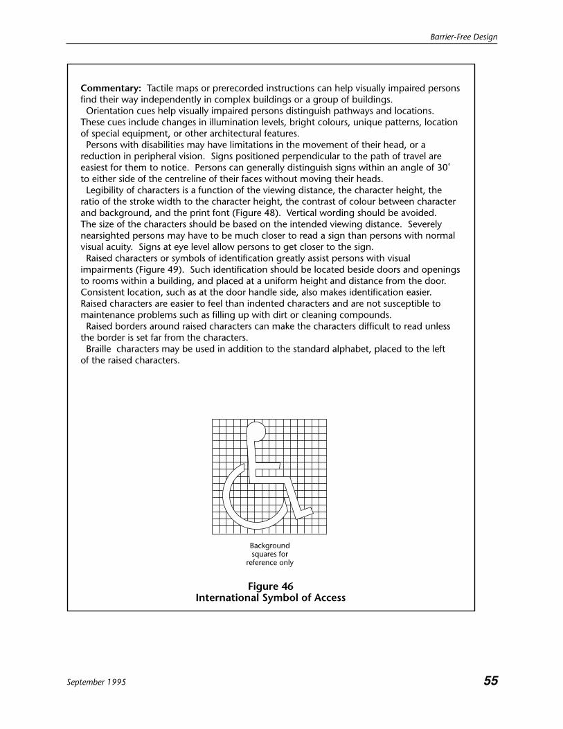
6.2.5.4Telephones for use by persons in wheelchairs shall be identified by the international symbol of access(Figure 46).
Commentary: Consideration should be given to a fold-down seat, provided that when it is folded up it does notinterfere with access for a person in a wheelchair. The preferred coin slot height is 1200 mm, but this height may not be achievable with some public telephoneunits.

CAN/CSA-B651-95
52 September 1995
Figure 44Height of Telephone and Shelf for TTD
750 min.1200 min.
Shelf spacefor TDD
250 min.
350 min.
720
min
.kn
ee c
lear
ance
1370
hig
hest
oper
able
poi
nt
Shelf spacefor TDD
250 min.
Commentary: Many persons who are deaf or hard of hearing use a Telecommunication Device for the Deaf (TDD) or Teletypewriter (TTY) with the standard telephone for communicating visually via the telephone system. Persons using TTYs or TDDs may carry their own unit and require shelf space for it beside or beneath the telephone. Pay telephones equipped with TDD/TTY are available and should be considered for public areas.
480 max.
Clear space
6.2.6 Telephones for Use by Persons Who are Deaf or Hard of Hearing
6.2.6.1A telephone shall comply with CSA Standard T515.
6.2.6.2A shelf at least 250 mm wide x 350 mm deep, with at least a 250 mm clear space above the shelf, shallbe provided to accommodate the use of a Teletype Device for the Deaf (TTY or TDD) (Figure 44).
6.2.6.3Telephones for use by persons who are deaf or hard of hearing shall be identified by the symbol ofaccessibility for persons who are deaf or hard of hearing (Figure 45(a)).

Barrier-Free Design
September 1995 53
Commentary: If more than one type of telephone is provided at a particular location, then at least one of each type (eg, card, coin, internal, taxi call) should be accessible to both persons who use wheelchairs and those who are hard of hearing.
(a) (b)
Figure 45Symbols of Accessibility for Persons Who Are Deaf or Hard of Hearing
6.2.7 Directional SignsWhen directional signs for telephones are installed, they shall include the appropriate access symbol(Figure 45(b)).
6.3 Assistive Listening SystemsInduction loops, infrared systems, and FM radio frequency systems shall be considered acceptable typesof assistive listening systems for persons who are hard of hearing.
Commentary: These types of assistive listening systems can be used by persons who are hard of hearing withor without hearing aids with T-switches or audio input capability and will not interfere with the listening enjoymentof people with normal hearing. All three systems transmit a signal which can be picked up by special-purposereceivers provided to those requiring them. Receivers for such systems can be equipped to be compatible withhearing aids with T-switches or audio input capability. Hard-wired systems will not meet this requirement unlessadequate provisions are made to accommodate persons with hearing aids. The choice and size (power) of thesystem will depend on the type of application and the size of the room. The accessibility symbol for persons whoare deaf or hard of hearing (Figure 45(a)) can be useful in indicating the existence of such a facility.
6.4 Signage
6.4.1 Character ProportionLetters and numbers on signs shall(a) be sans serif;(b) have Arabic numbers;(c) have a width-to-height ratio between 3:5 and 1:1; and(d) have a stroke-width-to-height ratio between 1:5 and 1:10

CAN/CSA-B651-95
54 September 1995
Commentary: An upper-case “X” should be used for character measurement. All signs should be consistentlyplaced and of uniform design so as to be readily seen. The size and intended viewing distance should complywith Table 4.
Table 4Character Height Dimensions for Viewing Distances
Minimum characterheight, mm
Maximum viewingdistance, mm
200 6000150 4600100 2500 75 2300 50 1500 25 750
6.4.2 ContrastCharacters and symbols shall be glare free and contrast with their background; either light characters on adark background or dark characters on a light background shall be used (Figure 48).
6.4.3 IlluminationThe minimum level of illumination on signs shall be 200 lx.
6.4.4 Tactile Characters or SymbolsCharacters, symbols, or pictographs on tactile signs shall(a) be raised at least 0.8 mm;(b) be between 16 and 50 mm high;(c) if letters or numbers, be sans serif; and(d) if wall mounted, have the centreline at a height of 1500 ± 25 mm (Figure 49).
6.4.5 Symbol of AccessIf accessible facilities are identified, then the international symbol of access shall be used (Figures 45, 46,and 47).
Barrier-Free Design
September 1995 55
Figure 46International Symbol of Access
Backgroundsquares for
reference only
Commentary: Tactile maps or prerecorded instructions can help visually impaired persons find their way independently in complex buildings or a group of buildings. Orientation cues help visually impaired persons distinguish pathways and locations. These cues include changes in illumination levels, bright colours, unique patterns, location of special equipment, or other architectural features. Persons with disabilities may have limitations in the movement of their head, or a reduction in peripheral vision. Signs positioned perpendicular to the path of travel are easiest for them to notice. Persons can generally distinguish signs within an angle of 30˚ to either side of the centreline of their faces without moving their heads. Legibility of characters is a function of the viewing distance, the character height, the ratio of the stroke width to the character height, the contrast of colour between character and background, and the print font (Figure 48). Vertical wording should be avoided. The size of the characters should be based on the intended viewing distance. Severely nearsighted persons may have to be much closer to read a sign than persons with normal visual acuity. Signs at eye level allow persons to get closer to the sign. Raised characters or symbols of identification greatly assist persons with visual impairments (Figure 49). Such identification should be located beside doors and openings to rooms within a building, and placed at a uniform height and distance from the door. Consistent location, such as at the door handle side, also makes identification easier. Raised characters are easier to feel than indented characters and are not susceptible to maintenance problems such as filling up with dirt or cleaning compounds. Raised borders around raised characters can make the characters difficult to read unless the border is set far from the characters. Braille characters may be used in addition to the standard alphabet, placed to the left of the raised characters.

CAN/CSA-B651-95
56 September 1995
Figure 47Example of Service Identification Signs Incorporating the
International Symbol of Access
Figure 48Readability of Printed Characters
Darkon
Light
Lighton
Dark
High contrastbetween charactersand background
Greatestreadability

Barrier-Free Design
September 1995 57
Figure 49Raised Characters of Symbols on Identification Signs
1500± 25
Raised0.8 min.
25 min.17
6.5 Detectable Warning SurfaceDetectable warnings on walking surfaces shall be(a) at least 900 mm long; and(b) of a texture and colour that contrasts with the surrounding walking surfaces.
Commentary: The minimum length of the detectable warning is established to ensure that persons will detect itregardless of stride length.
7. Parking Spaces and Passenger Loading Zones
7.1 Circulation RoutesCirculation routes adjacent to parking spaces shall be part of the accessible route to the building orfacility entrance and shall be accessible by a person in a wheelchair in accordance with Clause 4.1.
7.2 Car Parking SpacesCar parking spaces shall(a) be at least 2400 mm wide;(b) have an adjacent access aisle at least 1500 mm wide;(c) have a firm, slip-resistant, level surface; and(d) where surfaces are paved, have access aisles clearly indicated by markings (Figures 50, 51, and 52).

CAN/CSA-B651-95
58 September 1995
Figure 50Parking Stall
3900
2400
1500
Commentary: Parking spaces designated for persons with disabilities and accessible passenger loading zones that serve a particular building should be located on the shortest possible circulation route to an accessible entrance. In separate parking structures or lots that do not serve a particular building, accessible parking spaces should be located on the shortest possible circulation route to an accessible pedestrian entrance of the parking facility. The accessible route should not oblige persons in wheelchairs to pass behind vehicles which may be backing out. Two accessible parking spaces may share a common access aisle. The location of accessible parking spaces should be identified for drivers entering a parking lot or structure. Parked vehicle overhangs should not reduce the clear width of an accessible circulation route. All markings should be of a slip resistant type. It is not recommended to paint the entire surface of the accessible parking space if the paint will make the surface slippery when wet.

Barrier-Free Design
September 1995 59
Figure 51Parking Stall, Diagonal to Curb
Pathway toaccessiblebuilding entrance
1200 min. Curb ramp Sign on post
Symbol onpavement
Shared accessaisle
6300 min.
Meter
7000 min.
Sign on post
3900
min
.
Curb ramp
800 min.
Figure 52Parallel Parking Stalls
7.3 Van Parking Spaces
7.3.1 SizeVan parking spaces shall be at least 4600 mm wide, except for parallel parking spaces, which shall be atleast 2600 mm wide by 7400 mm long (Figures 53 and 54).

CAN/CSA-B651-95
60 September 1995
Curb ramp
Sign on post
Vertical signon building
4600min.
Shared accessaisle
Symbols onpavement
4600min.
Figure 53Van Parking Stall
Commentary: Vans require a wider parking stall because wheelchair entry into the van is often via a side door with a mechanical platform lift which extends outside the van. Additional manoeuvring space is required beyond the platform. For parallel van parking, space is required behind the stall because some vans have the wheelchair entry and mechanical platform lift at the back of the vehicle.
7.3.2 Height ClearanceVan parking spaces shall have a height clearance of at least 2750 mm at the parking space and along thevehicle access and egress routes.

Barrier-Free Design
June 1996(Replaces p. 61, September 1995) 61
Figure 54Parallel Van Parking Stall
2000min.
Curb rampSign on post Clearspace 20
00m
in.
2600
min
. Symbol onpavement
5400min.
2000min.
Commentary: Widening the sidewalk at the unloading area may be necessary to give wheelchair users adequate room to turn after using a vehicle side-lift.
7.4 Signs
7.4.1 Designated StallsAccessible parking stalls shall be designated as reserved for use by persons with disabilities by the(a) Uniform Traffic Control Sign, mounted vertically (Figure 55); and(b) international symbol of access on the pavement of the stall (Figure 46).

CAN/CSA-B651-95
June 199662 (Replaces p. 62, September 1995)
Figure 55Uniform Traffic Control Sign Identifying
Parking Spaces Reserved for Persons with Disabilities
Red
Blue
Green
Whitebackground
300 min.
600
min
.
�
7.4.2 Vertical SignsVertical signs shall be(a) at least 300 x 450 mm; and(b) installed at a height between 1500 mm and 2500 mm from the ground or floor surface to the centreof the sign.
7.4.3 Symbol of AccessSymbols on the pavement shall be(a) at least 1000 mm long;(b) located in the centre of the stall; and(c) in a colour strongly contrasting with the background pavement.

Barrier-Free Design
September 1995 63
Figure 56Sign Pointing to Designated Parking Spaces for
Persons with Disabilities
Blue
Green
Commentary: The vertical sign should be located to make it readily visible by a driver of a vehicle approaching the stall. Where the location of designated parking areas for persons with disabilities is not obvious or is distant from the approach viewpoints, directional signs should be placed along the route leading to the designated parking stalls (Figure 56).
Figure 57Access Aisle at Passenger Loading Zone
Curb ramp
6000 min.
1500
min
.
7.5 Passenger Loading Zones
7.5.1 Size and AccessPassenger loading zones shall(a) provide an access aisle at least 1500 mm wide and 6000 mm long adjacent and parallel to thevehicle pull-up space (Figure 57); and(b) have a curb ramp complying with Clause 4.4 where there are curbs between the access aisle and thevehicle pull-up space.

CAN/CSA-B651-95
64 September 1995
Figure 58Vertical Clearance at Passenger Loading Zone
Entrance
2750
min
.
Commentary: Where possible, covered passenger loading zones are desirable.
7.5.2 Vertical ClearanceA minimum vertical clearance of 2750 mm shall be provided at accessible passenger loading zones andalong vehicle access routes to such areas from site entrances (Figure 58).(b)
8. Seating Spaces
8.1 Seating at Tables and Counters
8.1.1 Clear Floor SpaceSeating spaces, such as that provided at counters, tables, or work surfaces for persons in wheelchairs,shall have a clear floor space not less than 750 x 1200 mm.
8.1.2 Clear Knee SpaceWhere a forward approach is used, a clear knee space at least 750 mm wide, 480 mm deep, and 680 mmhigh shall be provided which may overlap the clear floor space by a maximum of 480 mm (Figure 59).

Barrier-Free Design
September 1995 65
Figure 59Forward and Side Approach to Table or Counter
680min.
750min.
1200min.
480min. 750
min.1200min.
Commentary: Height and knee clearances at specialized work surfaces may have different requirements.
8.2 Viewing PositionsEach wheelchair viewing position shall be a clear, level ground or floor area of at least 850 × 120mm.

CAN/CSA-B651-95
66 September 1995
Figure 60Theatre Viewing Positions
Exit
850 min.1200 min.
Does notinterferewith seatingegress
EntranceExit
Does notinfringe onaislerequirements
EntranceExit
Exit
Commentary: Wheelchair spaces in theatres and other assembly areas should be an integral part of any seating plan. They should be dispersed throughout the seating area and may be created through the use of removable seating. Wheelchair seating areas should adjoin the accessible route and be adjacent to the means of egress in case of emergency. Viewing areas should be located to provide lines of sight comparable to those for all viewing areas. Two wheelchair spaces should be provided side-by-side in any one location with adjacent seating provided for ambulatory companions (Figures 60 and 61). Persons in wheelchairs usually sit higher than persons in standard seating and care should be taken that viewing positions for persons in wheelchairs are arranged so as not to obstruct the view of persons who may be seated behind (Figure 61).

Barrier-Free Design
September 1995 67
810 min.
Figure 61Stadium or Arena Viewing Positions
1200 min.
850
min
.
Clear view
Maintain requiredaisle width
9. Recreation Facilities
9.1 BenchesBenches shall(a) be adjacent to an accessible route;(b) be stable;(c) have the seat height between 450 and 500 mm from the ground;(d) have arm and back rests; and(e) have an adjacent level, firm ground surface at least 850 x 1200 mm.
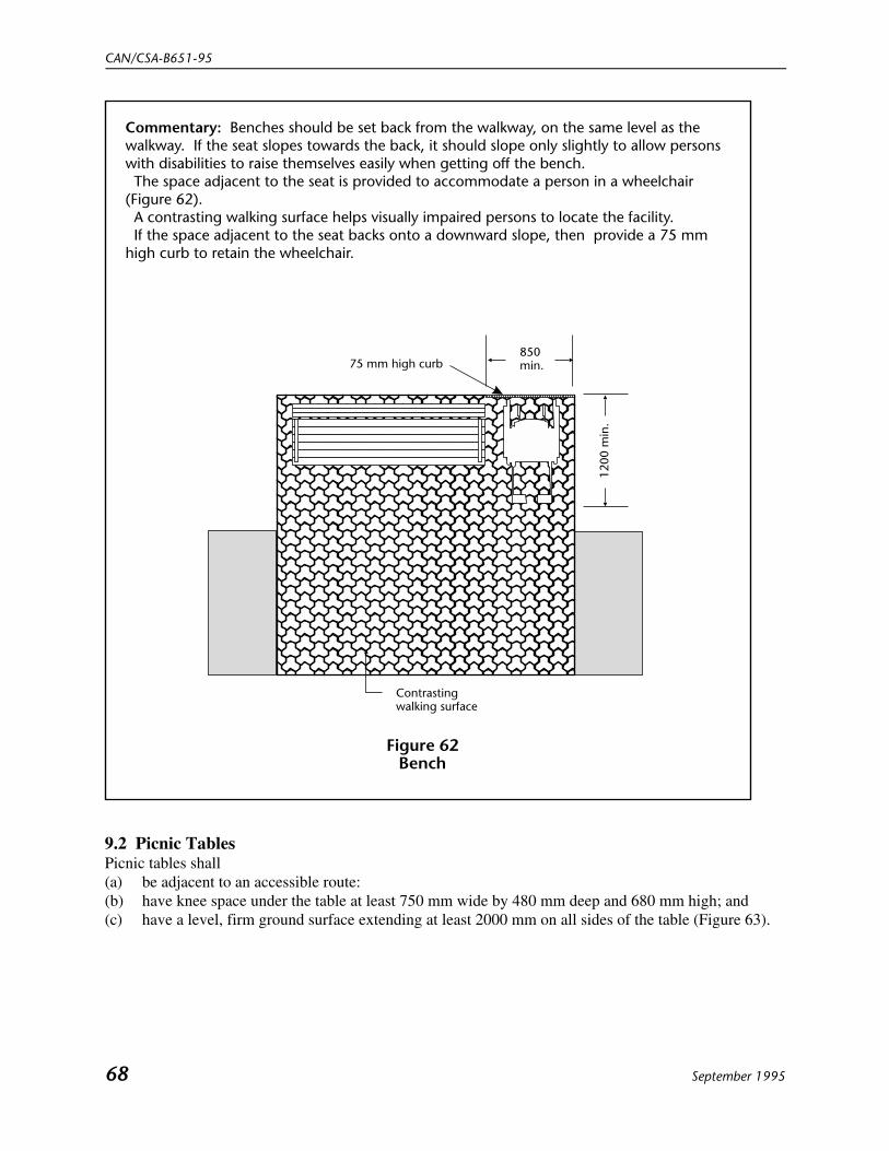
CAN/CSA-B651-95
68 September 1995
Figure 62Bench
Contrastingwalking surface
1200
min
.
75 mm high curb850min.
Commentary: Benches should be set back from the walkway, on the same level as the walkway. If the seat slopes towards the back, it should slope only slightly to allow persons with disabilities to raise themselves easily when getting off the bench. The space adjacent to the seat is provided to accommodate a person in a wheelchair (Figure 62). A contrasting walking surface helps visually impaired persons to locate the facility. If the space adjacent to the seat backs onto a downward slope, then provide a 75 mm high curb to retain the wheelchair.
9.2 Picnic TablesPicnic tables shall(a) be adjacent to an accessible route:(b) have knee space under the table at least 750 mm wide by 480 mm deep and 680 mm high; and(c) have a level, firm ground surface extending at least 2000 mm on all sides of the table (Figure 63).

Barrier-Free Design
September 1995 69
Figure 63Picnic Table
480min.
2000 min.
680
min
. 750
min
.
Firm level ground
2000 min.
2000
min
.20
00 m
in.
10. Residential Units
Commentary: This section describes two levels of accessibility: Basic Access and Complete Access. Requirements specified in the Basic Access section ensure a reasonable level of access that can accommodatevisitors in wheelchairs as well as temporarily disabled residents and elderly persons. While a person in awheelchair would be able to manoeuvre independently throughout the unit, the use of the kitchen, bathroom, orother functional areas may still be somewhat restricted. Basic Access describes requirements for dwelling unitssometimes referred to as “mobility”, “universally accessible”, or “adaptable” units. The Complete Access section specifies requirements additional to those in Clause 10.1 in order to ensureusability for residents in wheelchairs.
10.1 Basic Access
10.1.1 Circulation
10.1.1.1 Corridor and Path WidthsCorridor and path widths shall be at least(a) 920 mm wide for interior routes; and(b) 1200 mm wide for exterior routes.
Commentary: Corridor widths should allow for manoeuvring space at doorways (Figure 65).

CAN/CSA-B651-95
70 September 1995
Face ofstop
810 min.
Standardhinges
Face ofdoor
Face ofstop
810 min.
Swing-clearhinges
Face ofstop
810 min.
Standardhinges
Panicbar
(b)(a)
(c)
Face ofdoor
Figure 64Clear Opening of Doorway
10.1.1.2 Doors
10.1.1.2.1The minimum clear opening of doorways shall be 810 mm with the door open 90°, measured between theface of the door and the stop (Figure 64(a)).
10.1.1.2.2Doorways shall have wheelchair manoeuvring space on both sides of the door and a clear space besidethe latch as described in Table 5, except where access is only required from one side, such as to a closet(Figure 65).

Barrier-Free Design
September 1995 71
Table 5Manoeuvring Space at Doors, mm
ContextFloor space required Space beside
latchDepth WidthSide-hinged door
Front approach (Figure 65(a))Pull side 1500 1500 600
Push side 1200 1200 300 Latch side approach (Figure 65(b)) Pull side 1200 1500 600
Push side 1050 1500 600 Hinge side approach (Figure 65(c)) Pull side 1500 1500 600 Push side 1050 1350 450Sliding door (Figure 65(d)) Front approach 1250 900 50 Side approach 1050 1350 540
Commentary: Bathroom doors should swing out so that a person inside the bathroom does not fall against thedoor and block it. Consideration should be given to sliding and bi-fold doors which can be easier to operateand which require less wheelchair manoeuvring space.

CAN/CSA-B651-95
72 September 1995
1500min.
Pull Side
600min.
besidelatch
1500
min
.12
00m
in. 300
min.besidelatch
1200min.
(a) Front approach at hinged door
Figure 65Minimum Doorway Manoeuvring Space
Push Side
(Continued)

Barrier-Free Design
June 1996(Replaces p. 73, September 1995) 73
1500 min.
Pull Side
600min.beside latch
1050
min
.
Push Side
1200
min
.
1500 min.
1500 min.
Pull Side
600min.
besidelatch
1050
min
.
Push Side
1500
min
.
1350 min.
450min.
besidelatch
540min.
beside latch
1200
min
.
50 min. besidelatch
1050
min
.
1350 min.
(b) Latch side approachat hinged door
Figure 65 (Concluded)
(c) Hinge side approach athinged door
(d) Front and side approach at sliding door
900 min.
�

CAN/CSA-B651-95
June 199674 (Replaces p. 74, September 1995)
10.1.1.2.3Thresholds shall(a) be not more than 13 mm high;(b) at exterior sliding doors, be not more than 19 mm high; and(c) where over 6 mm high, be bevelled with a slope not more than 1:2.
Commentary: Wherever possible, thresholds should be avoided.
10.1.1.2.4The maximum force for pushing or pulling open a door shall be(a) 38 N for exterior hinged doors;(b) 22 N for interior hinged doors; and(c) 22 N for sliding or folding doors.
Commentary: These forces do not apply to the force required to retract latch bolts or disengage other devicesthat may hold the door in a closed position.
10.1.1.2.5 Operating devices such as handles, pulls, latches, and locks shall (a) be operable by one hand;(b) not require fine finger control, tight grasping, pinching, or twisting of the wrist to operate; and(c) be mounted between 400 and 1200 mm from the floor.
Commentary: Lever handles are preferred on latched doors. Care should be taken with sliding doors to ensurethat the operating mechanisms conform with this requirement. There are exterior residential doors that require two hands; one hand to hold the lock open while the other handis used simultaneously to turn the handle. These are not considered accessible.
10.1.1.2.6Where door viewers are provided, one shall be located at a height between 1100 and 1200 mm from thefloor and the other shall be located at the normal height for a standing adult.
10.1.1.3 Floor SurfacesFloor surfaces shall(a) be firm and slip resistant (see Appendix A);(b) have no abrupt changes in level except as described in Clause 10.1.1.2.3; and(c) if carpets or carpet tiles are used,
(i) be securely fixed;(ii) have a firm cushion, pad, or backing, where used;

Barrier-Free Design
September 1995 75
(iii) have a level loop, textured loop, level cut pile, or level cut/uncut pile texture with a maximumpad and pile height of 13 mm; and
(iv) have exposed edges of carpet fastened to floor surfaces and trim along the entire length of theexposed edge complying with Clause 10.1.1.2.3.
10.1.2 Controls and OutletsThe operable part of controls, such as thermostats, electrical switches, circuit breakers, locks andintercom buttons, microphones, and electrical and communication wall outlets shall be(a) located adjacent to a clear floor space which has a width of 750 mm;(b) located at a height between 400 and 1200 mm from the floor;(c) operable with one hand;(d) of a type which does not reuire tight grasping, pinching, or twisting of the wrist;(e) operable with a force less than 22 N; and(f) capable of being illuminated to a level of at least 100 lx.
10.1.3 WindowsOpening and locking mechanisms shall comply with the reuirements of Clause 10.1.2.
10.1.4 Visual AlarmsVisual alarms shall be lights that flash at a freuency of approximately 1 Hz in conjunction with the audible emergency alarms.
Commentary: Specialized systems using advanced technology may be substituted if equivalent protection isprovided for residents who are deaf or hard of hearing.
10.1.5 BathroomsBathrooms shall have(a) a space at least 1500 x 1500 mm for access to the toilet and the fixture itself and this access spacemay overlap access space for other fixtures;(b) the distance between the centreline of the toilet fixture and the adjacent wall between 460 and480 mm; and(c) beside the toilet, shower, and bathtub walls, structural support to allow the installation of grab barscapable of resisting a force of at least 1.3 kN applied vertically or horizontally (Figure 66).

CAN/CSA-B651-95
76 September 1995
Other fixturesmay be locatedadjacent toclear space
Figure 66Bathroom
800min.
1250min.
Location ofstructural supportsto allow instructionof grab-bars
700max.
900min.
460-480
1500 min.
10.1.6 KitchensThe minimum clearance between counters and all opposing base cabinets, countertops, appliances, orwalls in kitchens shall be 1200 mm, except in U-shaped kitchens, where the minimum clearance shall be1500 mm.
10.1.7 Laundry FacilitiesA clear floor space at least 750 x 1200 mm shall be provided in front of clothes washing and dryingequipment (Figure 67).

Barrier-Free Design
September 1995 77
Figure 67Laundry Facilities
1200 min.
750 min.
1200 min.
10.1.8 Outdoor Living AreasOutdoor living areas such as patios, balconies, or decks shall be(a) at least 1500 x 1500 mm;(b) adjacent to an accessible route; and(c) capable of being illuminated to a level of at least 100 lx at the floor level.
10.2 Complete Access
10.2.1 GeneralFor those units which are to be completely accessible, the requirements of Clause 10.2 in addition to therequirements of Clause 10.1 shall apply.
10.2.2 Elevating DevicesElevating devices for persons with disabilities in private residences shall comply with CSA StandardsCAN/CSA-B613, CAN/CSA-B355 and CAN/CSA-B44 as applicable.
10.2.3 Bathrooms
10.2.3.1 ToiletsToilets shall comply with Clause 10.1.5.
Commentary: Where individuals require higher toilet seats, seat height adapters are available.

CAN/CSA-B651-95
78 September 1995
Figure 68Grab Bars
1500 min. 1500 min.
Verticalgrab-baris optional
300max. 250
max.
600min.
450min.
750-850
460-480Front of
toilet seat
750-850600min.
10.2.3.1.1Toilets shall be equipped with horizontal grab bars which shall(a) comply with Clause 10.2.3.7;(b) be mounted on the side wall closest to the toilet extending from a point not more than 300 mmfrom the rear wall to at least 450 mm in front of the toilet seat;(c) be at least 600 mm long and be mounted on the wall behind the toilet; and(d) be mounted between 750 and 850 mm from the floor level (Figure 68).
Commentary: Where a vertical grab bar is installed, it should be located 250 mm in front of the toilet. Grab bardimensions should be measured to the centreline. Flip-down grab bars may be used.
10.2.3.1.2Toilet paper dispensers shall be located below the grab bar in line with the front of the toilet seat not lessthan 600 mm from the floor (Figure 68).

Barrier-Free Design
September 1995 79
10.2.3.2 Lavatory
10.2.3.2.1Lavatories shall(a) be mounted so that the minimum distance between the centreline of the fixture and the side wall is460 mm (Figure 69);(b) have the top located between 820 and 860 mm from the floor (Figure 69);(c) have a knee space at least 750 mm wide, 200 mm deep, and 680 mm high with an additional toespace at least 750 mm wide, 230 mm deep, and 230 mm high (Figure 69);(d) have a minimum clear floor space 750 mm wide and 1200 mm deep of which a maximum of 480mm in depth may be under the lavatory (Figure 69); and(e) have hot water and drain pipes insulated if they abut the clearances noted above.
10.2.3.2.2Faucets and other controls shall(a) have handles of the lever type (not self-closing) which are operable with a closed fist; or(b) be electronically controlled.
10.2.3.3 Bathroom AccessoriesWhere bathroom shelving such as a medicine cabinet or towel storage is provided it shall contain at leastone shelf located not more than 1200 mm from the floor.
10.2.3.4 MirrorsAt least one mirror with its bottom edge less than 1000 mm from the floor shall be provided (Figure69(b)).
10.2.3.5 Bathtubs
10.2.3.5.1 Floor SpaceA clear floor space at least 750 mm wide shall be provided in front of a bathtub. The lavatory canencroach a maximum of 300 mm into this floor space, providing there is clear knee and toe space underthe lavatory (Figure 69).

CAN/CSA-B651-95
80 September 1995
230 min.toe clearance
Figure 69Lavatory Clearances
200 min.kneeclearance
750min.
460min.
1000max.
480max.
1200max.
Clearspace
230 min.toeclearance
820-
860
720
min
.
680
min
.
(a) (b)
230min.
820-
860
10.2.3.5.2 Bathtub Grab BarsGrab bars shall(a) comply with Clause 10.2.3.7;(b) be at least 1200 mm long, located horizontally along the length of the bathtub, 180–280 mm abovethe bathtub rim; and(c) be at least 1200 mm long, located vertically at the foot end of the bathtub adjacent to the clear floorspace, with the lower end between 180 and 280 mm above the bathtub rim (Figure 70).
Commentary: Care should be taken to ensure that the vertical grab bar does not interfere with the showercurtain.
10.2.3.5.3 Bathtub ControlsFaucets and other controls shall(a) comply with Clause 10.2.3.6.4;(b) be located at the foot end of the bathtub between the centreline of the bathtub and the clear floorspace; and(c) be not more than 450 mm from the bathtub rim.

Barrier-Free Design
September 1995 81
Figure 70Bathtubs
750min.
300max.
Locationof controls
1200min.
180-280
450max.1200
min.
180-280
Clearspace
Commentary: It is desirable to have a seat 400 mm deep across the width of the bathtublocated at the end of the bathtub to allow easier access.
10.2.3.5.4 Shower HeadA shower head complying with Clause 10.2.3.6.4 shall be provided.
10.2.3.5.5 Bathtub EnclosuresEnclosures for bathtubs shall not(a) obstruct controls;(b) interfere with a person transferring from a wheelchair; and(c) have tracks mounted on the bathtub rim.
10.2.3.6 Shower Stalls
Commentary: Roll-in shower stalls accommodate persons who prefer to remain in a wheelchair while taking ashower. Shower stalls with a seat accommodate persons who prefer to transfer from a wheelchair to a fixedseat in the shower stall or persons who need to be seated while showering.

CAN/CSA-B651-95
82 September 1995
Figure 71Example of a Roll-In Shower Stall
Bevelledthreshold13 max.
700-800
750min.
900min.
Clearspace
1200min.
1200max.
900min.
750min.
1500min.
10.2.3.6.1 Roll-in Shower Stalls
10.2.3.6.1.1Roll-in shower stalls shall have interior dimensions of at least 750 x 1500 mm.
10.2.3.6.1.2The minimum clear floor space in front of the shower entrance shall be 900 x 1200 mm with the 1200mm dimension parallel to the shower entrance (Figure 71).
10.2.3.6.1.3Grab bars for roll-in shower stalls shall(a) comply with the requirements of Clause 10.2.3.7;(b) be one L-shaped bar or two grab bars in L-shaped configuration; and(c) be at least 750 x 900 mm with the 900 mm arm set horizontally between 700 and 800 mm from theshower floor (Figure 71).
10.2.3.6.1.4Controls for roll-in shower stalls shall be mounted on the long wall above the grab bar, not more than1200 mm from the floor.
10.2.3.6.1.5Curbs for roll-in shower stalls shall be 6–13 mm high, bevelled at a slope of 1:2.

Barrier-Free Design
September 1995 83
10.2.3.6.2 Shower Stalls with Seat
Commentary: A seat which folds to a vertical position when not in use will allow persons to use the shower in aseated or standing position. A seat of a colour that contrasts with surrounding surfaces improves safety forvisually impaired persons.
10.2.3.6.2.1Shower stalls with a seat shall have interior dimensions of at least 900 x 900 mm.
10.2.3.6.2.2In shower stalls with a seat, the seat shall(a) be on the wall opposite the controls;(b) be a minimum of 400 mm wide extending the full depth of the stall, less a space allowed for ashower curtain; and(c) have its top 430–480 mm from the floor.
10.2.3.6.2.3The minimum clear floor space in front of the shower entrance shall be 900 x 1200 mm with the 1200mm dimension parallel to the shower entrance, starting from the stall wall opposite the seat, where a seatis provided (Figure 72).
10.2.3.6.2.4Grab bars in shower stalls with a seat shall(a) comply with the requirements of Clause 10.2.3.7;(b) have one grab bar at least 750 mm long installed horizontally on the back wall between 700 and800 mm from the shower floor (Figure 72); and(c) have another grab bar at least 750 mm long installed vertically 80–120 mm from the front edgestarting between 700 and 800 mm from the floor (Figure 72).
10.2.3.6.2.5For shower stalls with a seat, all controls, faucets, and the shower unit shall be(a) mounted on the wall opposite the seat not more than 1200 mm from the floor; and(b) accessible from outside the stall.
10.2.3.6.2.6Curbs in shower stalls with a seat shall be not higher than 100 mm.

CAN/CSA-B651-95
84 September 1995
Figure 72Example of Shower Stall with Seat
430-480
900min.
700-800
900min.
400min.
100max.
1200max.
900min.
1200min.
700-800
80-120
Clearspace
Commentary: Curb colour should contrast with the flooring colour to reduce thepossibility of dangerous tripping.
10.2.3.6.3 Shower Controls
10.2.3.6.3.1Faucets and other controls shall be hand operated or electronically controlled.
10.2.3.6.3.2Hand-operated controls shall(a) be operable with one hand;(b) require no tight grasping, pinching, or twisting of the wrist; and(c) require a force less than 22 N to activate.
10.2.3.6.3.3Temperature of the water supplied to the shower shall be controlled by a pressure-equalizing valve or byan automatic thermostatically controlled valve.
10.2.3.6.4 Shower Heads
10.2.3.6.4.1A shower head shall(a) be of the hand-held type;(b) be provided with a hose not less than 1500 mm long; and(c) allow use in fixed position.

Barrier-Free Design
September 1995 85
10.2.3.6.4.2Where the shower head is mounted on a vertical bar, the bar shall be installed so as not to obstruct theuse of grab bars.
10.2.3.6.5 Shower EnclosuresEnclosures for shower stalls shall not obstruct controls or obstruct transfer from wheelchairs onto showerseats.
10.2.3.6.6 Shower FloorsThe floor of the shower shall be slip resistant. (See Appendix A for additional guidance on slipresistance.)
10.2.3.7 Grab Bars
10.2.3.7.1 Size and SpacingGrab bars shall(a) be slip resistant;(b) have a diameter 30–40 mm, or a shape that provides an equivalent gripping surface; and(c) have a space of 35–45 mm between the wall and the grab bar where mounted adjacent to a wall.
10.2.3.7.2 Structural StrengthGrab bars shall be installed to resist a force at least 1.3 kN applied vertically or horizontally.
10.2.3.7.3 SafetyA grab bar and any wall or other surface adjacent to it shall be free of any sharp or abrasive elements.
10.2.4 Kitchens
10.2.4.1 Clearance Between CountersClearances shall comply with Clause 10.1.6 (Figure 73).

CAN/CSA-B651-95
86 September 1995
Figure 73Plan of Parallel Kitchen
Dishwasher
Side-by-side full-heightdoors for refrigeratorand freezer unit
1200
min
.
750 x 1200 min.Clear floor spacefor access
Full heightpull-outpantryshelves
10.2.4.2 Clear Floor SpaceA clear floor space of at least 750 x 1200 mm shall be provided for side approach at all appliances in thekitchen, including the range or cooktop, oven, refrigerator/freezer, dishwasher, and trash compactor.
10.2.4.3 ControlsAll controls in kitchens shall comply with Clause 10.1.2.
10.2.4.4 Work SurfacesAt least one work surface shall(a) be at least 750 mm wide x 600 mm deep;(b) be at a height between 810 and 860 mm;(c) have a clear floor space of at least 750 mm x 1200 mm which may extend up to 480 mmunderneath the work surface;(d) have knee space at least 750 mm wide, 480 mm deep, and 680 mm high (Figures 74 and 75);(e) have no sharp or abrasive surfaces under it; and(f) have accessible electrical outlets at the side or the front of it.

Barrier-Free Design
September 1995 87
Figure 74Work Surface and Sink
810-860920typ.
480 max.
1200 min.
750 min.
Figure 75Cooking Unit, Oven, and Pantry Storage
Commentary: A pull-out workboard below the standard countertop level is desirable.
810-860
750 min.
1200 min.
480 max.
a
b
c
d
e
f
a
bd
fe
c
Full height pull-outpantry shelves"D" type pulls oncupboards and drawersPull-out shelfunder wall ovenElectric outlets accessiblefrom seated positionPull-out workboardsfor easy access and useKnee space undercountertop cooking unit

CAN/CSA-B651-95
88 September 1995
10.2.4.5 Base CabinetsBase cabinets shall have a toe space at least 150 mm deep and 230 mm high.
10.2.4.6 SinksSinks shall(a) be mounted with the rim height between 810 and 860 mm from the floor;(b) have a knee space at least 750 mm wide ’ 250 mm deep ’ 680 mm high plus a toe space at least 750mm wide ’ 230 mm deep ’ 230 mm high;(c) have a clear floor space at least 750 ’ 1200 mm in front of it; up to 480 mm of this space mayextend under it;(d) have faucets with handles of the lever type that are operable with a closed fist or have faucets thatare electronically controlled;(e) have no sharp or abrasive surfaces under it; and(f) have hot water, drain pipes, and its underside insulated if they abut the clearances noted above(Figure 74).
10.2.4.7 CooktopsRanges and cooktops shall have(a) controls which do not require reaching across the burners to operate;(b) insulation or other protection on the underside where knee space is provided; and(c) a clear floor space at least 750 ’ 1200 mm which may overlap a knee space by up to 480 mm(Figure 75).
10.2.4.8 OvensOvens shall have(a) controls located on the front panel; and(b) for side-opening oven doors, the latch next to a horizontal surface, or a pull-out shelf under it whichshall
(i) extend the full width of the oven; and(ii) pull out not less than 250 mm (Figure 75).
Commentary: It is recommended that ovens be self-cleaning. Side-opening doors are preferred over bottom-hinged doors to avoid burns. Microwave ovens are also very convenient.
10.2.4.9 Refrigerators/FreezersRefrigerators/freezers shall be self-defrosting and of the(a) vertical side-by-side type (Figure 74); or(b) over-and-under type with
(i) at least 50% of the freezer space below 1370 mm from the floor; and(ii) 100% of the refrigerator space and controls below 1370 mm from the floor.
10.2.4.10 DishwashersWhere dishwashers are installed, they shall be front-loading.

Barrier-Free Design
September 1995 89
Figure 76Clothes Storage
1200
max
.
1400
max
.
400
min
.A
cces
sibi
lity
rang
e
10.2.4.11 Kitchen StorageCabinets, drawers, and shelf storage areas shall have(a) at least one shelf not more than 1200 mm from the floor where it is above a work counter;(b) door pulls or handles mounted close to the
(i) bottom of upper cabinet doors; and(ii) top of base cabinet doors; and
(c) a toe space at least 150 mm deep and 230 mm high provided in base cabinets.
Commentary: Full-height storage cabinets provide a good range of accessible storage. This is particularlydesirable because, in accessible kitchens, the amount of base storage is reduced by the knee space provisions. “D” type pulls can be used easily by persons with hand disabilities. A good basic rule for kitchen storage is toprovide shelving above counter height and drawers below.
10.2.4.12 Clothes StorageClothes storage shall have(a) a clothes rail not higher than 1400 mm;(b) at least three shelves between 400 and 1200 mm from the floor; and
(c) a clear floor space at least 750 x 1200 mm in front of the storage area (Figure 76).
10.2.5 Miscellaneous ComponentsComponents such as garbage disposal units, hose bibs, and post boxes shall have(a) a clear floor area at least 750 x 1200 mm in front of the component; and(b) controls and operating parts which comply with Clause 10.1.2.

CAN/CSA-B651-95
90 September 1995
Appendix ASlip Resistance of Floor Finishes
Note: This Appendix is not a mandatory part of this Standard.
Table A1 Slip Resistance of Typical Flooring Surfaces
Source: British Standard 5395 Part 1:1977, Code of Practice for the Design of Straight Stairs.
Material
Slip resistance*
Dry andunpolished Wet Remark
Clay tiles (Carborundum finish) very god very good May be suitable for external stairs.
Carpet very good good
Clay tiles (textured) very good good May be suitable for external stairs.
Cork tiles very good good
PVC with nonslip granules very good good
PVC very good poor to fair Slip resistance when wet may beimproved if PVC is textured. Edges
of sheet liable to cause tripping if notfixed firmly to base.
Rubber (sheets or tiles) very good very poor Not suitable near entrance doors.
Mastic asphalt good good
Vinyl asbestos tiles good fair
Linoleum good poor to fair Edges of sheets may cause trippingif not securely fixed to base.
Concrete good poor to fair
If a textured finish or a nonslipaggregate is used, slip resistance valuewhen wet may be increased to good.
(Continued)

Barrier-Free Design
September 1995 91
Table A1 (Concluded)
Material
Slip resistance*
Dry andunpolished
Wet Remark
Concrete (abrasive grain finish) very good very good Both these finishes should provide service levelsequal to clay tiles with Carborum or texturesfinishes. A light broom finish is commonly usedfor slip resistance on municipal sidewalks wherethey have givenmany years of service.
Concrete (broom textured) very good very good
Granolithic good poor to fair Slip resistance when wet may beimproved to good by incorporatingCarborundum finish.
Cast iron good poor to fair Slip resistance may be acceptablewhen wet if open treads are used.
Clay tiles good poor to fair Slip resistance when wet and polishedvery poor.
Terrazzo
good poor to fair Nonslip nosing necessary on stairs. Slip resistance when polished or if polish is transferred by shoes from adjacent surfaces very poor.
*Very good means surface suitable for areas where special care is required, approximates to coefficifent of friction(cof) > 0.75.Good means surface satisfactory for normal use, approximates to cof 0.4 < 0.75. Poor to fair means surface below acceptable safety limits, approximates to cof 0.2 < 0.4. Very poor means surface unsafe, approximates to cof < 0.2.Note: Care should be taken with polishes and cleaners so that the slip resistance is not reduced.

CAN/CSA-B651-95
92 September 1995
Appendix BAnthropometrics
Note: This Appendix is not a mandatory part of this Standard.
B1. Scope
B1.1This Appendix contains dimensions which can be used for guidance when designing facilities andequipment to be used by persons with disabilities.
B2. Reach Ranges for a Person in a Wheelchair
B2.1 Forward Reach
B2.1.1. Without ObstructionThe maximum forward reach is 1200 mm from the floor and the minimum forward reach is 380 mm fromthe floor (Figure B1).
B2.1.2 Over ObstructionThe maximum forward reach over an obstruction 600 mm deep for touch reach and 500 mm deep forgrasp reach is 1100 mm from the floor (Figure B2).
B2.2 Side Reach
B2.2.1 Without ObstructionThe maximum side reach is 1400 mm from the floor and the minimum side reach is 230 mm from thefloor (Figure B3).
B2.2.2 Over ObstructionThe maximum side reach over an obstruction 860 mm high and 600 mm deep for touch reach and 500mm deep for grasp reach is 1200 mm from the floor (Figure B4).
Commentary: When designing for a specific individual, the actual reach limitations should be taken intoaccount.

Barrier-Free Design
September 1995 93
Figure B1Forward Rearch Without Obstruction
380 min.12
00 m
ax.
Figure B2Forward Reach Over Obstruction
600 max.touch reach
500 max.grasp reach
1100
max
.

CAN/CSA-B651-95
94 September 1995
Figure B4Side Reach Over Obstruction
600 max.touch reach
500 max.grasp reach
860
max
.
1200
max
.Figure B3
Side Reach Without Obstruction
1400
max
.230 min.

Barrier-Free Design
June 1996(Replaces p. 95, September 1995) 95
Figure B5Typical Dimensions of Wheelchairs Commonly Used by Adults
1200length
1100
-130
0
LapSeatToe
handle
arm rest
920
760
200 48
0 675
660width
Foldedwheelchair
300
760
B3. Wheelchair Dimensions
B3.1Figure B5 describes some typical dimensions. Manual and electric wheelchairs have similar dimensions,but electric wheelchairs do not always have the same manoeuvrability/capability as manual wheelchairs,and are much heavier. Electric wheelchairs cannot be folded. For more information on wheelchairs see the following CSA Standards:CAN/CSA-Z323.4.2-M86, Wheelchairs—Determination of Overall Dimensions, Mass, and TurningSpace;CAN/CSA-Z323.4.3-M89, Wheelchairs—Determination of Static Stability;CAN/CSA-Z323.4.4-M89, Wheelchairs—Determination of Brake Effectiveness;CAN/CSA-Z323.4.6-M89, Wheelchairs—Determination of Maximum Speed, Acceleration, andRetardation of Electric Wheelchairs;CAN/CSA-Z323.4.7-M89, Wheelchairs—Determination of Obstacle-Climbing Ability of ElectricWheelchairs.
�
B4. Walkway Widths for Persons Using Crutches
B4.1Although people who use walking aids can manoeuvre through door openings of 810 mm clear width,they need wider passageways and walks for comfortable gaits (Figure B6). Crutch tips, often extendingdown at a wide angle, are a hazard in narrow passageways where they might not be seen by otherpedestrians.

CAN/CSA-B651-95
June 199696 (Replaces p. 96, September 1995)
Figure B6Comfortable Walking Width for Persons Using Crutches
300
No obstructionshould projectinto this zone
920

Barrier-Free Design
September 1995 97
Appendix CElevator Requirements
Note: This Appendix is not a mandatory part of this Standard.
C1.
C1.1The following is a reproduction of Appendix E of CSA Standard CAN/CSA-B44-M94.
Appendix EElevator Reuirements for Persons with PhysicalDisabilitiesNote: This Appendix is not a mandatory part of the Standard. It is provided for reference where requirements forpersons with physical disabilities are to be incorporated in elevators.
E1. Scope
E1.1This Appendix contains reuirements intended to make passenger elevators usable by persons withphysical disabilities. These reuirements are in addition to, or modifications of, certainreuirements specified elsewhere in this Standard.
E2. Operation and Levelling
E2.1The elevator shall be automatic and be provided with a two-way automatic-maintaining levellingdevice to maintain the floor level to ±13 mm.
E3. Door Operation
E3.1Power-operated horizontally-sliding car and landing doors opened and closed by automatic meansshall be provided.
E4. Door Size
E4.1The minimum clear width for elevator doors shall be 910 mm.

CAN/CSA-B651-95
98 September 1995
E5. Door Protective and Reopening Device
E5.1Doors shall be provided with a door-reopening device that will function to stop and reopen a cardoor and an adjacent hoist way door to at least 910 mm, in case the car door is obstructed whileclosing. This reopening device shall also be capable of sensing an object or person in the path ofa closing door at a nominal 125 ± 25 mm and 735 ± 25 mm above the floor without reuiring contact for activation.
E5.2Door-reopening devices shall remain effective for a period of not less than 20 s.
E6. Door Delay (Passenger Service Time)
E6.1From the time the doors start to open, a minimum period of 4 s shall elapse before the doors startto close, if it is a hall call and 3 s if it is a car call. This time may be reduced after operation ofthe door close button.
E7. Car Inside
E7.1The minimum distance between the walls or between wall and door, excluding return panels,shall be not less than 1725 × 1370 mm. The minimum distance from wall to return panel shall benot less than 1295 mm.
E8. Car Controls
E8.1Controls shall be readily accessible from a wheelchair upon entering an elevator (see Figure E1).
E8.2Emergency controls and door-operating buttons shall be grouped together at the bottom of thecontrol panel. The centreline of the alarm button and the emergency-stop switch shall be not lessthan 890 mm from the floor. The centreline of the highest floor button shall be no higher that1370 mm from the floor. Other controls may be located where it is convenient.
E8.3Floor registration buttons shall be a minimum 19 mm in size and they may be raised, flush, orrecessed. The depth of flush or recessed buttons when they are being operated shall not exceed10 mm.

Barrier-Free Design
September 1995 99
Figure E1Car Controls
16 min. 19 min.1370 mm max.
890 mm min.
800-920 mm to Topof Handrail
Floor
17
15
7
5
3
1
18
16
8
6
4
2
E8.4Arabic numerals shall be adjacent on the left of the floor buttons on a contrasting colour background. Markings shall be a minimum of 16 mm high and raised a minimum of 0.75 mm. Permanently attached plates are acceptable. Where the call buttons are mechanical, the raised markings may be on the buttons.
E8.5Symbols as indicated in Clause 3.6.1.10 shall be used to assist in readily identifying essential controls.
E8.6Visual and momentary audible indication shall be provided to show each call registered and visual indication shall be extinguished when the call is answered.

CAN/CSA-B651-95
100 September 1995
E9. Car Position Indicator
E9.1An indicator shall be provided in the car to show the position of the car in the hoist way, byilluminating the indication corresponding to the landing at which the car is stopped or passing. Indication characters shall be on a contrasting colour background and a minimum of 16 mm inheight.
E10. Telephone
E10.1The telephone shall be located a maximum of 1220 mm from the floor with a minimum cordlength of 900 mm.
E10.2The international symbol for telephones shall be located on the telephone cabinet in a contrastingcolour. The symbol shall be a minimum of 38 mm high and raised a minimum of 0.75 mm. Permanently attached plates are acceptable. Telephones shall be equipped with a receiver thatgenerates a magnetic field in the area of the receiver cap and the telephone shall have a volumecontrol and shall comply with CSA Standard T515.
E11. Floor Covering
E11.1The floor shall have a firm and slip resistant surface that permits easy movement of wheelchairs.
E12. Handrails
E12.1Handrails shall be provided on all non-access walls at a height of 800 to 920 mm with a space of35-45 mm between the rails and wall.
E13. Illumination
E13.1The illumination at the car controls and landing sill shall be not less than 100 lx.
Barrier-Free Design
September 1995 101
E14. Hall Buttons
E14.1The centreline of the hall call buttons shall be 1070 ± 25 mm above the floor. Buttons shall be aminimum of 20 mm in size, and shall be mounted one above the other.
E14.2Visual indication shall be provided to show each call that is registered and that is extinguishedwhen the call is answered.
E15. Hall or In-Car Lanterns
E15.1Hall or in-car lanterns shall be provided. The centreline of the fixture shall be a minimum of1830 mm above the floor. An audible signal, shall be provided when the elevator stops at thelanding. Visual elements shall be a minimum of 60 mm in the smallest direction.
E16. Floor Designations
E16.1Arabic numerals a minimum of 50 mm high and raised at least 0.75 mm shall be placed on bothsides of the door jambs, with the centre line at 1500 ± 25 mm from the floor to identify the floorlevel.
Commentary: Where the depth of the elevator cab makes it difficult for wheelchair users to turn around,provide a mirror on the rear wall so they can see the car position indicator above the door.
C2. Other Considerations
C2.1In addition to the above requirements of Appendix E of CSA Standard CAN/CSA-B44, it is alsorecommended that the following be considered:(a) as the car passes or stops at a floor, an audible signal should sound inside the elevator at aminimum of 20 dB at a frequency no higher than 1500 Hz; and(b) there should be a colour contrast between the car sill and the building floor and between the doorframe and the wall.

CAN/CSA-B651-95
102 September 1995
Index
AAdaptable units 10.1
Aisles 10.1.1.1Floor area 10.1.1.3, 10.1.5,10.1.7, 10.1.8
Alarms 6.1, 10.1.4Anthropometrics App. BApartments 10Application of requirements 1.2Areas of refuge 4.9Assistive listening systems 6.3Audio amplification systems 6.3Audio loops 6.3Auditorium seating 8.2Automatic doors 4.2.8
BBathrooms 10.1.5, 10.2.3
Accessories 10.2.3.3Balconies—see Thresholds & outdoor
living areasBathtubs
Controls 5.8.3, 10.2.3.5.3Enclosures 5.8.5, 10.2.3.5.5Floor space 5.8.1, 10.2.3.5.1Residential, basic 10.1.5Residential, complete 10.2.3Seat 5.8, 10.2.3.5.3
Basic access 10.1Benches 9.1Braille 6.4.5
CCarpets
Strong patterns 4.5.3Changes in level 3.3.2Checkout lanes 4.1.1Children 1.3Circulation 4
Residential 10.1.1Clearances for wheelchair 3.1Closers on doors—see Doors
Clothes dryer or washer—see LaundryClothes hanger or rod—see StorageCoat hook 5.2.1(c)Cobblestone 3.3.1Colour contrast
Detectable warning surface 4.5.3Nosings 4.5.2Shower curb 5.8.2.6
Communications 6Complete access 10, 10.2Controls
Floor space 3.2.1Force to use 3.2.3Height 3.2.2
Illumination 3.2.4Operation 3.2.4Residential 10.1.2
Cooktop 10.2.4.7Counters
Kitchen 10.2.4.1 Seating 8.1
Cross slopeCurb ramps 4.4.1.2Ramps 4.3.2
Cupboards—see Storage, clothesCurbs for showers 5.8.2.6Curb ramps 4.4
Flared sides 4.4.4Location 4.4.5Slope
Cross slope 4.4.1.2Running slope 4.4.1.1
Surfaces 4.4.3Width 4.4.2
DDetectable warning surfaces 4.5.3Directional signs 6.2.7Dishwashers 10.2.4.10Doors
Clear opening 10.1.1.2.1Closet 10.1.1.2.2Clear width 4.2.1Closers 4.2.6.3Double leaf 4.2.2Hardware 4.2.6

Barrier-Free Design
September 1995 103
In series 4.2.4Manoeuvring space 4.2.3Opening force 4.2.7Power-assisted 4.2.8Pulls (D-type) 5.2.2(d), (e)Residential 10.1.1.2Revolving 4.2.8Sliding 4.2.6.2Thresholds 4.2.5Toilet stall 5.2.2Viewers 10.1.1.2.6
Drinking fountains 5.10Controls 5.10.2Floor space 5.10.3Location 5.10.3.2Spouts 5.10.1Wall-mounted 5.10.3.2
Dwelling units—see Residences
EEgress 4.9.1Electrical outlets 10.1.2Elevators 4.7, App. CEmergency call switch 5.6.2Entrances 4.2.8 Exit 4.9.1Exposed aggregate paving 3.3.1Exterior residential doors
10.1.1.2.5FFaucets 5.4.2, 10.2.3.2.2
Lavatories 5.4.2Fire alarms 6.1, 10.1.4Firefighters elevator 4.9.1Fire safety—see Areas of refugeFlared sides of curb ramps 4.4.4Floors
Clearance for wheelchair 3.1Slip resistance App. ALevel changes 3.3.2Residential 10.1.1.3Showers 5.8.6
Flush controlsToilet 5.3.3, 5.3.4
FM systems 6.3Forward reach App. B2.1Freezer 10.2.4.9
GGarage—see ParkingGarbage disposal units 10.2.5Gates 4.2.8Grab bars 5.9
Flip-up 5.2.1Safety 5.9.3Size & spacing 5.9.1Strength 5.9.2Toilet 5.3.4, 10.2.3.1.1
GradientCirculation 4.12Curb ramps 4.4,Ramps 4.3.1, 4.3.2
Grating 3.3.4Ground—see Floors
HHand-held shower spray 5.8.4Handrails 4.6
Ramps 4.3.8Recessed 4.6.2Stairs 4.5.4
Hardware 4.2.6Headroom 3.4.5Hotel rooms—see ResidencesHousing 10
I Illumination
Controls 3.2.4Elevators App. CStairs 4.5.3Telephones 6.2.4
Indented characters 6.4.5Induction loops 6.3 Infrared systems 6.3International symbol of
access 6.4.5, 7.4.1Parking 7.4.3Telephones 6.2.5.4
Islands 4.4.6
KKitchens
Basic 10.1.6Complete 10.2.4
CAN/CSA-B651-95
104 September 1995
Controls 10.2.4.3Cooktops 10.2.4.7Counters 10.2.4.1Freezers 10.2.4.9Ovens 10.2.4.8Refrigerators 10.2.4.9Sinks 10.2.4.6Storage 10.2.4.11Work surfaces 10.2.4.4
Knee spaceLavatories 5.4.1(c)
LLandings
Exit stair for area of refuge 4.9.1Laundry 10.1.7Lavatories 5.4, 10.2.3.2.1Letter Box 10.2.5Lever handles 10.1.1.2.5Life safety—see Areas of refugeLighting—see IlluminationListening systems 6.3
MMail box 10.2.5Mirrors 5.5.2, 10.2.3.4
NNosings of stairs
4.5.2
OOperating mechanisms—see ControlsOrientation cues 6.4.5Outdoor living areas 10.1.8Ovens 10.2.4.8
PParking 7
Car space 7.2Circulation route 7.1Height 7.3.2Signs 7.4Van space 7.3
Passenger loading area 7.5Access 7.5.1
Size 7.5.1Vertical clearance 7.5.2
Paths 4.1Length 4.1.2Pedestrian crosswalks
Curb ramp location 4.4.4.1, 4.4.5Platform lifts 4.8.1Picnic tables 9.2Post box 10.2.5Power-assisted doors 4.2.8Protruding objects 3.4Projecting objects 3.4Public telephones 6.2
RRamps 4.3
Curb ramps 4.4Edge protection 4.3.7Handrails 4.3.8Landings 4.3.4Length 4.3.1Outdoor conditions 4.3.6Slope
Cross slope 4.3.2Running slope 4.3.1
Surfaces 4.3.5Width 4.3.3
Ranges 10.2.4.7Reach ranges App. BRefuge—see Areas of refugeRecreation facilities 9References 2Refrigerators 10.2.4.9Residential units 10Revolving doors 4.2.8Risers of stairs 4.5.1
Open risers 4.5.3Roll-in shower stall 5.8.1Routes 4.1Rugs—see Carpets
SSeating
Bathtub 5.7.1Benches 9.1Counters 8.1Shower 5.8.2, 5.8.2.2

Barrier-Free Design
September 1995 105
Tables 8.1Telephone 6.2.5.4Viewing positions 8.2
Scope 1Shower stalls
5.8, 10.2.3.6Controls 5.8.3, 10.2.3.6.3Enclosures 5.8.5, 10.2.3.6.5Floors 5.8.6, 10.2.3.6.6Grab bars 5.8.1.3, 5.8.1.4, 5.9, 10.2.3.7Heads 5.8.4, 10.2.3.6.4Roll-in 5.8.1, 10.2.3.6.1With seat
5.8.2, 10.2.3.6.2Side reach App. B2.2Signage 6.4 Car parking 7.4
Character height 6.4.1Contrast 6.4.2Illumination 6.4.3Symbol of access 6.4.5Tactile characters 6.4.4Van parking 7.4.3
Sinks 10.2.4.6Sliding doors
Table 2, 5Slip resistance of floors App. ASlope—see GradientSmoke-protected 4.9.1Stairs
Detectable warning surfaces 4.5.3Handrails 4.5.4, 4.6Nosings 4.5.2Risers 4.5.1Treads 4.5.1
Steps—see StairsStorage
Kitchen 10.2.4.5, 10.2.4.11Clothes 10.2.4.12
SymbolInternational symbol of access Fig. 48Hearing impairment Fig. 45
TTactile
Characters 6.4.4Maps 6.4.5Warnings 6.5
TablesPicnic 9.2
Work 8.1.1Telecommunication devices for the deaf
(TDD) 6.2.6.2Telephones 6.2
Controls 6.2.2Cord length 6.2.3Elevator App. CFor persons who are deaf or hard of hearing
6.2.6For persons in wheelchairs 6.2.5Illumination 6.2.4Protruding parts 6.2.1Seat 6.2.5.4Signage
6.2.7, 6.2.5.4, 6.2.6.3Theatre seating
8.2
Thresholds 4.5.2Residential 10.1.1.2.3
Toe clearance Fig. 37Toilets 5.3
Flush controls 5.3.3Grab bars 5.3.4Location 5.3.2Paper dispenser 5.2.1
Residential basic 10.1.5Stalls 5.2Wall-hung 5.3.4
Towel dispensers 5.6.2Treads of stairs 4.5.1Turning space for wheelchair 4.1.1Turnstiles 4.2.8
UUniversal access—see Basic accessUnisex rooms—see Washroom
VVan parking 7.3Vanities 5.5.3Visual alarms 10.1.4, 6.1
WWalkway widths App. B4Walls
Protruding objects 3.4Warning surface textures 6.5Wash basin—see Lavatories

CAN/CSA-B651-95
106 September 1995
WashroomAccessories 5.5Identification 5.1Individual 5.6Lavatories 5.4Toilets 5.3Toilet stalls 5.2Unisex washroom 5.6Unit washroom 5.6
Waste receptacles 5.6.2Water closet—see ToiletWheelchair
Clearances 3.1Dimensions App. B3
Windows 10.1.3Work areas 8Work surfaces 8
In kitchens 10.2.4.4