Embed Size (px)
Citation preview
CDG160-OP-LIT (2010-06) 1
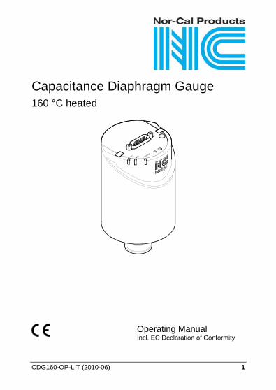
Capacitance Diaphragm Gauge 160 °C heated
Operating Manual Incl. EC Declaration of Conformity
2 CDG160-OP-LIT (2010-06)
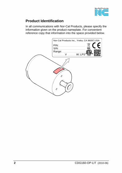
Product Identification In all communications with Nor-Cal Products, please specify the information given on the product nameplate. For convenient reference copy that information into the space provided below.
P/N:S/N:Range: V W; LPS
Nor-Cal Products Inc., Yreka, CA 96097,USA
CDG160-OP-LIT (2010-06) 3
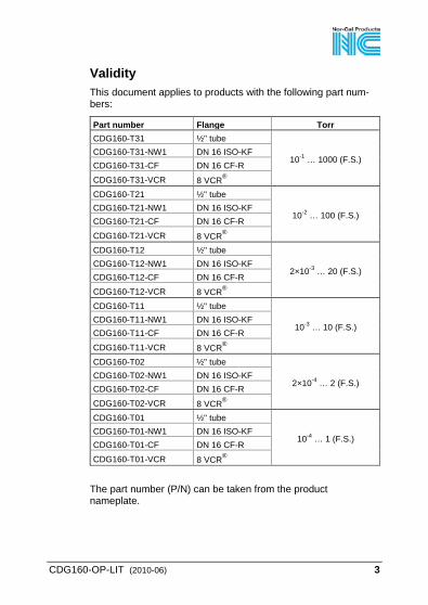
Validity This document applies to products with the following part num-bers:
Part number Flange Torr CDG160-T31 ½" tube
10-1 … 1000 (F.S.) CDG160-T31-NW1 DN 16 ISO-KF CDG160-T31-CF DN 16 CF-R CDG160-T31-VCR 8 VCR® CDG160-T21 ½" tube
10-2 … 100 (F.S.) CDG160-T21-NW1 DN 16 ISO-KF CDG160-T21-CF DN 16 CF-R CDG160-T21-VCR 8 VCR® CDG160-T12 ½" tube
2×10⁻³ … 20 (F.S.) CDG160-T12-NW1 DN 16 ISO-KF CDG160-T12-CF DN 16 CF-R CDG160-T12-VCR 8 VCR® CDG160-T11 ½" tube
10-3 … 10 (F.S.) CDG160-T11-NW1 DN 16 ISO-KF CDG160-T11-CF DN 16 CF-R
CDG160-T11-VCR 8 VCR® CDG160-T02 ½" tube
2×10⁻⁴ … 2 (F.S.) CDG160-T02-NW1 DN 16 ISO-KF CDG160-T02-CF DN 16 CF-R CDG160-T02-VCR 8 VCR® CDG160-T01 ½" tube
10-4 … 1 (F.S.) CDG160-T01-NW1 DN 16 ISO-KF CDG160-T01-CF DN 16 CF-R CDG160-T01-VCR 8 VCR®
The part number (P/N) can be taken from the product nameplate.
4 CDG160-OP-LIT (2010-06)
If not indicated otherwise in the legends, the illustrations in this document correspond to Capacitance Diaphragm Gauges with the DN 16 ISO-KF vacuum connection. They apply to gauges with other vacuum connections by analogy. We reserve the right to make technical changes without prior notice. All dimensions in mm.
Intended Use The temperature controlled Capacitance Diaphragm Gauges are intended for absolute pressure measurement of gases in their respective pressure ranges (→ 3). The gauges can be operated in connection with a Nor-Cal Vacuum Gauge Controller or another appropriate controller.
Functional Principle A ceramic diaphragm is deflected by pressure. The deflection is measured capacitively and converted into an analog linear out-put signal by the digital electronics. The output signal is independent of the gas type. Very accurate pressure measurement is achieved by heating the sensor to a constant temperature of 160°C which results in a compensation of changes in the ambient conditions and a reduced deposition of process products and by-products in process applications. An integrated baffle protects the sensor against coating.
Trademark VCR® Swagelok Marketing Co.
CDG160-OP-LIT (2010-06) 5
Patents EP 1070239, 1040333 US Patents 6528008, 6591687, 7107855, 7140085
Scope of Delivery 1× Capacitance Diaphragm Gauge 1× Insulation shell 1× Pin 1× Calibration Test Report 1× Operating Manual
6 CDG160-OP-LIT (2010-06)
Contents
Product Identification 2 Validity 3 Intended Use 4 Functional Principle 4 Trademark 4 Patents 5 Scope of Delivery 5 1 Safety 8 1.1 Symbols Used 8 1.2 Personnel Qualifications 8 1.3 General Safety Instructions 9 1.4 Liability and Warranty 9 2 Technical Data 10 3 Installation 15 3.1 Vacuum Connection 15 3.2 Power Connection 19 4 Operation 22 4.1 Status Indication 22 4.2 Zeroing the Gauge 23 4.2.1 <ZERO> Adjustment 23 4.2.2 <ZERO> Adjustment with Ramp Function 25 4.3 Switching Functions 27 4.3.1 Adjusting the Setpoints 28 4.4 Activating the Factory Setting (Factory Reset) 30 5 Deinstallation 31 5.1 Power Connection 31 5.2 Vacuum connection 31 6 Maintenance, Repair 34 7 Returning the Product 34 8 Disposal 35
CDG160-OP-LIT (2010-06) 7
Further Information 36 ETL Certification 36 Declaration of Contamination 37 EC Declaration of Conformity 38
For cross-references within this document, the symbol (→ XY) is used, for cross-references to further documents, listed under "Further Information", the symbol (→ [Z]).
8 CDG160-OP-LIT (2010-06)
1 Safety
1.1 Symbols Used
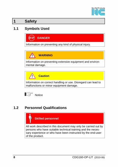
DANGER
Information on preventing any kind of physical injury.
WARNING
Information on preventing extensive equipment and environ-mental damage.
Caution
Information on correct handling or use. Disregard can lead to malfunctions or minor equipment damage.
Notice
1.2 Personnel Qualifications
Skilled personnel
All work described in this document may only be carried out by persons who have suitable technical training and the neces-sary experience or who have been instructed by the end-user of the product.
CDG160-OP-LIT (2010-06) 9
1.3 General Safety Instructions • Adhere to the applicable regulations and take the necessary
precautions for the process media used. Consider possible reactions with the product materials.
• Adhere to the applicable regulations and take the necessary precautions for all work you are going to do and consider the safety instructions in this document.
• Before beginning to work, find out whether any vacuum com-ponents are contaminated. Adhere to the relevant regulations and take the necessary precautions when handling contamin-ated parts.
Communicate the safety instructions to all other users.
1.4 Liability and Warranty Nor-Cal Products assumes no liability and the warranty becomes null and void if the end-user or third parties • disregard the information in this document • use the product in a non-conforming manner • make any kind of interventions (modifications, alterations etc.)
on the product • use the product with accessories not listed in the product
documentation.
The end-user assumes the responsibility in conjunction with the process media used. Gauge failures due to contamination are not covered by the warranty.
10 CDG160-OP-LIT (2010-06)
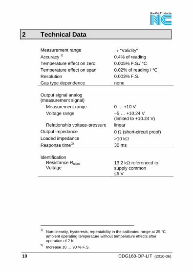
2 Technical Data
Measurement range → "Validity" Accuracy 1 0.4% of reading ) Temperature effect on zero 0.005% F.S./ °C Temperature effect on span 0.02% of reading / °C Resolution 0.003% F.S. Gas type dependence none Output signal analog (measurement signal)
Measurement range 0 … +10 V Voltage range –5 … +10.24 V
(limited to +10.24 V) Relationship voltage-pressure linear
Output impedance 0 Ω (short-circuit proof) Loaded impedance >10 kΩ Response time2 30 ms ) Identification
Resistance RIdent Voltage
13.2 kΩ referenced to supply common ≤5 V
1) Non-linearity, hysteresis, repeatability in the calibrated range at 25 °C
ambient operating temperature without temperature effects after operation of 2 h.
2) Increase 10 … 90 % F.S.
CDG160-OP-LIT (2010-06) 11
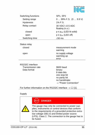
Switching functions SP1, SP2 Setting range 0 … 99% F.S. (0 … 9.9 V) Hysteresis 1% F.S. Relay contact 30 VDC/ ≤0.5 ADC
floating (n.o.) closed p ≤ pSP (LED lit solid) open p ≥ pSP (LED off)
Switching time ≤50 ms Status relay
closed measurement mode warning
open no supply voltage warming up error
RS232C interface
Transmission rate Data format
9600 baud binary 8 data bits one stop bit no parity bit no handshake → "Power Connection"
For further information on the RS232C interface → [1]. Supply
DANGER
The gauge may only be connected to power sup-plies, instruments or control devices that conform to the requirements of a grounded protective extra-low voltage (SELV) and limited power source (LPS), Class 2. The connection to the gauge has to be fused.
12 CDG160-OP-LIT (2010-06)
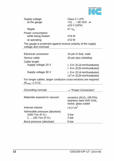
Supply voltage at the gauge
Class 2 / LPS +21 … +30 VDC or ±15 V (±5%)
Ripple ≤1 Vpp Power consumption
while being heated ≤18 W
at operating ≤12 W The gauge is protected against reverse polarity of the supply voltage and overload. Electrical connection 15-pin D-Sub, male Sensor cable 15-pin plus shielding Cable length
Supply voltage 24 V ≤ 5 m (0.14 mm²/conductor) ≤ 8 m (0.25 mm²/conductor)
Supply voltage 30 V ≤ 9 m (0.14 mm²/conductor) ≤17 m (0.25 mm²/conductor)
For longer cables, larger conductor cross-sections are required (Rcable ≤1.0 Ω). Grounding concept → "Power Connection" Materials exposed to vacuum ceramics (Al2O3 ≥99.5%),
stainless steel AISI 316L, nickel, glass solder
Internal volume ≤4.2 cm3 Admissible pressure (absolute)
1000 Torr (F.S.) 1 … 100 Torr (F.S.)
3 bar 2 bar
Burst pressure (absolute) 6 bar
CDG160-OP-LIT (2010-06) 13
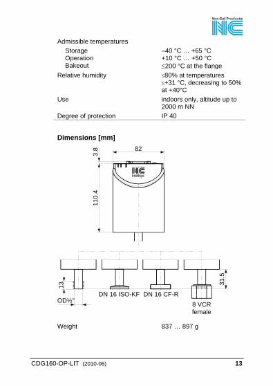
Admissible temperatures Storage Operation Bakeout
–40 °C … +65 °C +10 °C … +50 °C ≤200 °C at the flange
Relative humidity ≤80% at temperatures ≤+31 °C, decreasing to 50% at +40°C
Use indoors only, altitude up to 2000 m NN
Degree of protection IP 40
Dimensions [mm]
8 VCRfemale
DN 16 ISO-KF
82
110.
4
DN 16 CF-ROD½"
31.5
3.8
13
Weight 837 … 897 g
14 CDG160-OP-LIT (2010-06)
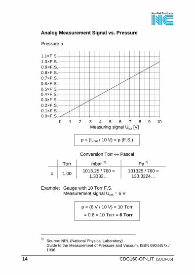
Analog Measurement Signal vs. Pressure
1 2 3 4 5 6 7 8 9 100
0.9×F.S.
0.5×F.S.0.6×F.S.
1.0×F.S.
0.7×F.S.0.8×F.S.
0.1×F.S.0.2×F.S.0.3×F.S.0.4×F.S.
1.1×F.S.
Pressure p
Measuring signal Uout [V]
0.0×F.S.
p = (Uout / 10 V) × p (F.S.)
Conversion Torr ↔ Pascal
Torr mbar 3 Pa ) 3)
c 1.00 1013.25 / 760 = 1.3332…
101325 / 760 = 133.3224…
Example: Gauge with 10 Torr F.S.
Measurement signal Uout = 6 V
p = (6 V / 10 V) × 10 Torr
= 0.6 × 10 Torr = 6 Torr
3) Source: NPL (National Physical Laboratory)
Guide to the Measurement of Pressure and Vacuum, ISBN 0904457x / 1998
CDG160-OP-LIT (2010-06) 15
3 Installation
WARNING
WARNING: fragile components The ceramic sensor may be damaged by impacts. Do not drop the product and prevent shocks and impacts.
3.1 Vacuum Connection
DANGER
DANGER: overpressure in the vacuum system >1 bar Injury caused by released parts and harm caused by escaping process gases can result if clamps are opened while the vacuum system is pressurized. Do not open any clamps while the vacuum system is pressurized. Use the type clamps which are suited to overpressure.
DANGER
DANGER: overpressure in the vacuum system >2.5 bar KF flange connections with elastomer seals (e.g. O-rings) cannot withstand such pressures. Process media can thus leak and possibly damage your health. Use O-rings provided with an outer centering ring.
16 CDG160-OP-LIT (2010-06)
DANGER
DANGER: protective ground Products that are not correctly connected to ground can be extremely hazardous in the event of a fault. Electrically connect the gauge to the grounded vacuum chamber. This connection must conform to the requirements of a protective connection ac-cording to EN 61010: • CF and VCR flanges fulfill this requirement. • For gauges with a KF flange, use a conductive
metallic clamping ring. • For gauges with a ½" tube, take appropriate
measures to fulfill this requirement.
Caution
Caution: vacuum component Dirt and damages impair the function of the vac-uum component. When handling vacuum components, take appro-priate measures to ensure cleanliness and prevent damages.
Caution
Caution: dirt sensitive area Touching the product or parts thereof with bare hands increases the desorption rate. Always wear clean, lint-free gloves and use clean tools when working in this area.
CDG160-OP-LIT (2010-06) 17
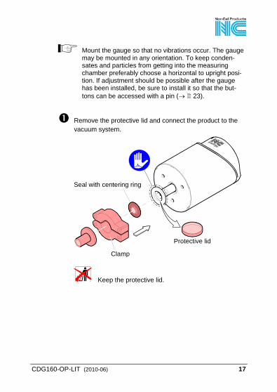
Mount the gauge so that no vibrations occur. The gauge may be mounted in any orientation. To keep conden-sates and particles from getting into the measuring chamber preferably choose a horizontal to upright posi-tion. If adjustment should be possible after the gauge has been installed, be sure to install it so that the but-tons can be accessed with a pin (→ 23).
Remove the protective lid and connect the product to the vacuum system.
Seal with centering ring
Protective lid
Clamp
Keep the protective lid.
18 CDG160-OP-LIT (2010-06)
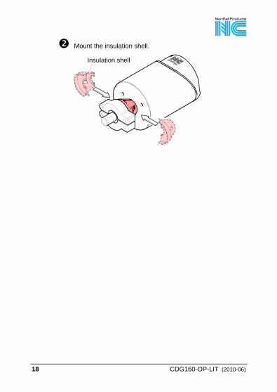
Mount the insulation shell.
Insulation shell
CDG160-OP-LIT (2010-06) 19
3.2 Power Connection
Make sure the vacuum connection is properly made (→ 15).
DANGER
The gauge may only be connected to power sup-plies, instruments or control devices that conform to the requirements of a grounded protective extra-low voltage (SELV) and limited power source (LPS), Class 2. The connection to the gauge has to be fused.
Ground loops, differences of potential, or EMC problems may affect the measurement signal. For optimum signal quality, please do observe the following notes:
• Connect the cable shield to ground on one side via the chassis ground. Do not connect the other side of the shield.
• Connect the supply common with protective ground directly at the power supply.
• Use differential measurement input (signal common and supply common conducted separately).
• Potential difference between supply common and housing ≤18 V (overvoltage protection).
20 CDG160-OP-LIT (2010-06)
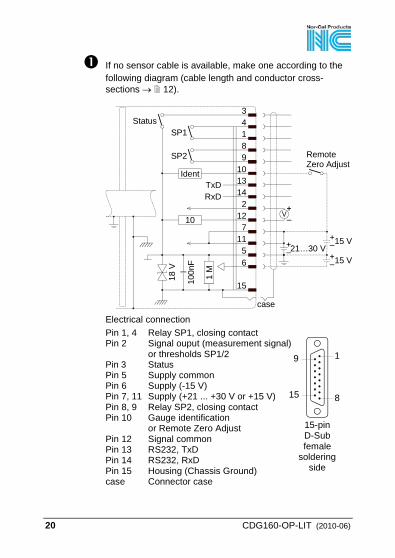
If no sensor cable is available, make one according to the following diagram (cable length and conductor cross-sections → 12).
15 8
9 1
15-pinD-Subfemale
solderingside
Electrical connectionPin 1, 4 Relay SP1, closing contactPin 2 Signal ouput (measurement signal) or thresholds SP1/2Pin 3 StatusPin 5 Supply commonPin 6 Supply (-15 V)Pin 7, 11 Supply (+21 ... +30 V or +15 V)Pin 8, 9 Relay SP2, closing contactPin 10 Gauge identification or Remote Zero AdjustPin 12 Signal commonPin 13 RS232, TxDPin 14 RS232, RxDPin 15 Housing (Chassis Ground)case Connector case
case
15 V
15 V21…30 V
RemoteZero Adjust
1 M
4189
10Ident13142
TxDRxD
127
115
15100n
F
18 V
10
6
3
SP1
SP2
Status
CDG160-OP-LIT (2010-06) 21
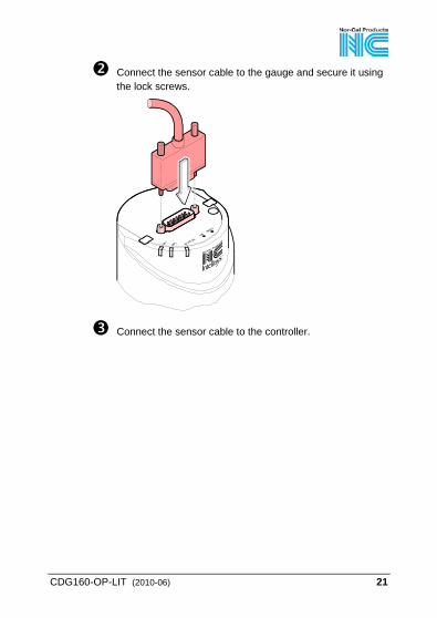
Connect the sensor cable to the gauge and secure it using the lock screws.
Connect the sensor cable to the controller.
22 CDG160-OP-LIT (2010-06)
4 Operation Put the gauge into operation. If you are using a Nor-Cal con-troller, define the measurement range.
A warm-up time of at least 2 hours should be allowed; for precise pressure measurements a warm-up time of at least 4 hours is required.
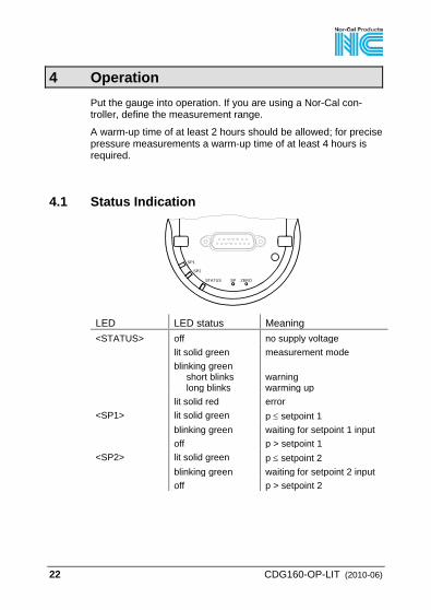
4.1 Status Indication
SP1
SP2
STATUS SP ZERO
LED LED status Meaning <STATUS> off no supply voltage lit solid green measurement mode blinking green
short blinks long blinks
warning warming up
lit solid red error <SP1> lit solid green p ≤ setpoint 1 blinking green waiting for setpoint 1 input off p > setpoint 1 <SP2> lit solid green p ≤ setpoint 2 blinking green waiting for setpoint 2 input off p > setpoint 2
CDG160-OP-LIT (2010-06) 23
4.2 Zeroing the Gauge The gauge is factory calibrated while "standing upright" (→ "Calibration Test Report").
We recommend performing a zero adjustment, when the gauge is operated for the first time.
Due to long time operation or contamination, a zero drift could occur and zero adjustment may become necessary. For adjusting the zero, operate the gauge under the same con-stant ambient conditions and in the same mounting orientation as normally. The output signal (measuring signal) is depending on the moun-ting orientation. The signal difference between the vertical and horizontal mounting orientation is:
F.S. ∆U / 90° 1000 Torr ≈2 mV
100 Torr ≈10 mV
10 Torr ≈50 mV
1 Torr ≈300 mV
If the gauge is operated via a controller, the zero of the whole measuring system has to be adjusted on the controller: first, adjust the zero of the gauge and then, the zero of the controller.
4.2.1 <ZERO> Adjustment
The zero can be adjusted via • the <ZERO> button on the gauge, • the digital input "Remote Zero" (briefly apply the
supply voltage (+21 … +30 V) to pin 10), • the RS232C interface (→ [1]), • a Nor-Cal Vacuum Gauge Controller.
While the gauge is being heated and/or under atmos-pheric pressure, the zeroing function is locked in order for operating errors to be prevented.
24 CDG160-OP-LIT (2010-06)
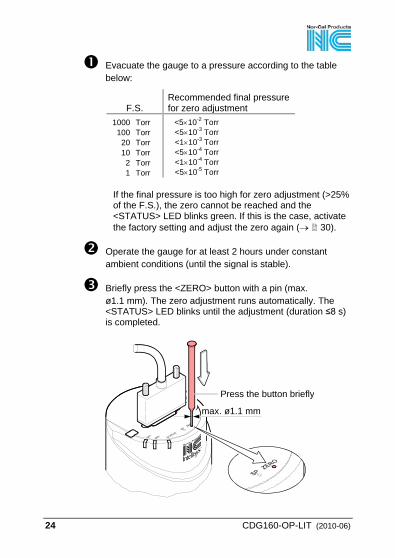
Evacuate the gauge to a pressure according to the table below:
F.S. Recommended final pressure for zero adjustment
1000 Torr 100 Torr 20 Torr 10 Torr 2 Torr 1 Torr
<5×10⁻² Torr <5×10⁻³ Torr <1×10⁻³ Torr <5×10⁻⁴ Torr <1×10⁻⁴ Torr <5×10⁻⁵ Torr
If the final pressure is too high for zero adjustment (>25% of the F.S.), the zero cannot be reached and the <STATUS> LED blinks green. If this is the case, activate the factory setting and adjust the zero again (→ 30).
Operate the gauge for at least 2 hours under constant ambient conditions (until the signal is stable).
Briefly press the <ZERO> button with a pin (max. ø1.1 mm). The zero adjustment runs automatically. The <STATUS> LED blinks until the adjustment (duration ≤8 s) is completed.
Press the button briefly
max. ø1.1 mm
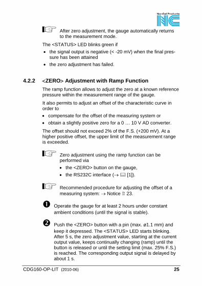
CDG160-OP-LIT (2010-06) 25
After zero adjustment, the gauge automatically returns to the measurement mode.
The <STATUS> LED blinks green if • the signal output is negative (< -20 mV) when the final pres-
sure has been attained • the zero adjustment has failed.
4.2.2 <ZERO> Adjustment with Ramp Function The ramp function allows to adjust the zero at a known reference pressure within the measurement range of the gauge.
It also permits to adjust an offset of the characteristic curve in order to • compensate for the offset of the measuring system or • obtain a slightly positive zero for a 0 … 10 V AD converter.
The offset should not exceed 2% of the F.S. (+200 mV). At a higher positive offset, the upper limit of the measurement range is exceeded.
Zero adjustment using the ramp function can be performed via • the <ZERO> button on the gauge, • the RS232C interface (→ [1]).
Recommended procedure for adjusting the offset of a measuring system: → Notice 23.
Operate the gauge for at least 2 hours under constant ambient conditions (until the signal is stable).
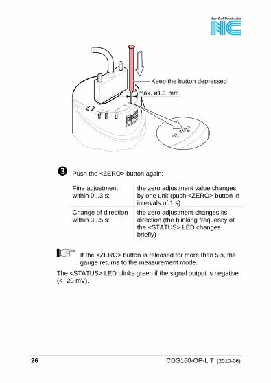
Push the <ZERO> button with a pin (max. ø1.1 mm) and keep it depressed. The <STATUS> LED starts blinking. After 5 s, the zero adjustment value, starting at the current output value, keeps continually changing (ramp) until the button is released or until the setting limit (max. 25% F.S.) is reached. The corresponding output signal is delayed by about 1 s.
26 CDG160-OP-LIT (2010-06)
Keep the button depressed
max. ø1.1 mm
Push the <ZERO> button again:
Fine adjustment within 0...3 s:
the zero adjustment value changes by one unit (push <ZERO> button in intervals of 1 s)
Change of direction within 3...5 s:
the zero adjustment changes its direction (the blinking frequency of the <STATUS> LED changes briefly)
If the <ZERO> button is released for more than 5 s, the gauge returns to the measurement mode.
The <STATUS> LED blinks green if the signal output is negative (< -20 mV).
CDG160-OP-LIT (2010-06) 27
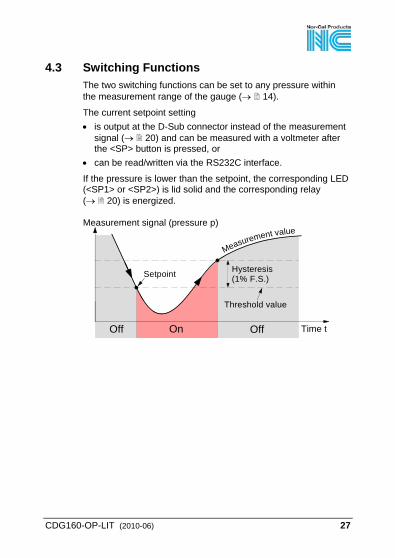
4.3 Switching Functions The two switching functions can be set to any pressure within the measurement range of the gauge (→ 14).
The current setpoint setting • is output at the D-Sub connector instead of the measurement
signal (→ 20) and can be measured with a voltmeter after the <SP> button is pressed, or
• can be read/written via the RS232C interface.
If the pressure is lower than the setpoint, the corresponding LED (<SP1> or <SP2>) is lid solid and the corresponding relay (→ 20) is energized.
Measurement signal (pressure p)
Time t
Measurement value
OffOn
Hysteresis(1% F.S.)
Off
Threshold value
Setpoint
28 CDG160-OP-LIT (2010-06)
4.3.1 Adjusting the Setpoints
The setpoints can be adjusted via • the buttons on the gauge, • the RS232C interface (→ [1]).
DANGER
DANGER: malfunction If processes are controlled via the signal output, keep in mind that by pushing the <SP> button the measurement signal is suppressed and the cor-responding threshold value is output instead. This can cause malfunctions. Push the <SP> button only if you are sure that no damages can arise from a malfunction.
Adjusting Setpoint <1>
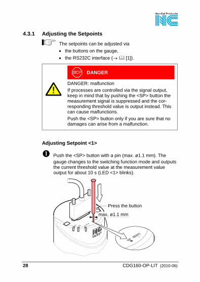
Push the <SP> button with a pin (max. ø1.1 mm). The gauge changes to the switching function mode and outputs the current threshold value at the measurement value output for about 10 s (LED <1> blinks).
Press the button
max. ø1.1 mm
CDG160-OP-LIT (2010-06) 29
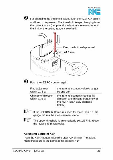
For changing the threshold value, push the <ZERO> button and keep it depressed. The threshold keeps changing from the current value (ramp) until the button is released or until the limit of the setting range is reached.
Keep the button depressed
max. ø1.1 mm
Push the <ZERO> button again:
Fine adjustment within 0...3 s:
the zero adjustment value changes by one unit
Change of direction within 3...5 s:
the zero adjustment changes its direction (the blinking frequency of the <STATUS> LED changes briefly)
If the <ZERO> button is released for more than 5 s, the gauge returns the measurement mode.
The upper threshold is automatically set 1% F.S. above the lower one (hysteresis).
Adjusting Setpoint <2> Push the <SP> button twice (the LED <2> blinks). The adjust-ment procedure is the same as for setpoint <1>.
30 CDG160-OP-LIT (2010-06)
4.4 Activating the Factory Setting (Factory Reset) All user defined parameters (e.g. zero, filter) are restored to their default values.
Loading of the default parameters is irreversible.
Loading the default parameters:
Put the gauge out of operation.
Keep the <ZERO> button depressed for at least 5 s while the gauge is being put into operation (Power ON).
CDG160-OP-LIT (2010-06) 31
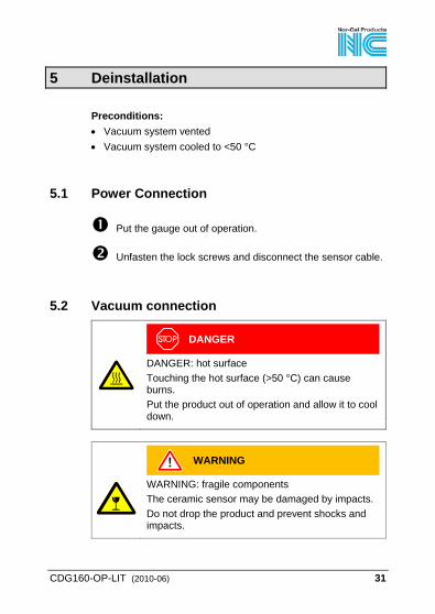
5 Deinstallation
Preconditions: • Vacuum system vented • Vacuum system cooled to <50 °C
5.1 Power Connection
Put the gauge out of operation.
Unfasten the lock screws and disconnect the sensor cable.
5.2 Vacuum connection
DANGER
DANGER: hot surface Touching the hot surface (>50 °C) can cause burns. Put the product out of operation and allow it to cool down.
WARNING
WARNING: fragile components The ceramic sensor may be damaged by impacts. Do not drop the product and prevent shocks and impacts.
32 CDG160-OP-LIT (2010-06)
DANGER
DANGER: contaminated parts Contaminated parts can be detrimental to health and environment. Before beginning to work, find out whether any parts are contaminated. Adhere to the relevant regulations and take the necessary precautions when handling contaminated parts.
Caution
Caution: vacuum component Dirt and damages impair the function of the vac-uum component. When handling vacuum components, take appro-priate measures to ensure cleanliness and prevent damages.
Caution
Caution: dirt sensitive area Touching the product or parts thereof with bare hands increases the desorption rate. Always wear clean, lint-free gloves and use clean tools when working in this area.

CDG160-OP-LIT (2010-06) 33
Remove the insulation shell.
Insulation shell
both sides open
Remove the gauge from the vacuum system and install the protective lid.
Seal with centering ring
Protective lidClamp
34 CDG160-OP-LIT (2010-06)
6 Maintenance, Repair Under clean operating conditions, the product requires no main-tenance.
Gauge failures due to contamination are not covered by the warranty. We recommend checking the zero at regular intervals (→ 23).
Nor-Cal assumes no liability and the warranty becomes null and void if any repair work is carried out by the end-user or third parties.
7 Returning the Product
WARNING
WARNING: forwarding contaminated products Contaminated products (e.g. radioactive, toxic, caustic or microbiological hazard) can be detrimen-tal to health and environment. Products returned to Nor-Cal should preferably be free of harmful substances. Adhere to the forward-ing regulations of all involved countries and for-warding companies and enclose a duly completed declaration of contamination.
Products that are not clearly declared as "free of harmful sub-stances" are decontaminated at the expense of the customer. Products not accompanied by a duly completed declaration of contamination are returned to the sender at his own expense.
CDG160-OP-LIT (2010-06) 35
8 Disposal
DANGER
DANGER: contaminated parts Contaminated parts can be detrimental to health and environment. Before beginning to work, find out whether any parts are contaminated. Adhere to the relevant regulations and take the necessary precautions when handling contaminated parts.
N
WARNING
WARNING: substances detrimental to the environ-ment Products or parts thereof (mechanical and electric components, operating fluids etc.) can be detrimen-tal to the environment. Dispose of such substances in accordance with the relevant local regulations.
Separating the components After disassembling the product, separate its components ac-cording to the following criteria: • Contaminated components
Contaminated components (radioactive, toxic, caustic or bio-logical hazard etc.) must be decontaminated in accordance with the relevant national regulations, separated according to their materials, and disposed of.
• Other components Such components must be separated according to their ma-terials and recycled.
36 CDG160-OP-LIT (2010-06)
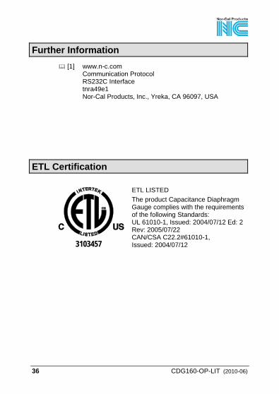
Further Information [1] www.n-c.com
Communication Protocol RS232C Interface tnra49e1 Nor-Cal Products, Inc., Yreka, CA 96097, USA
ETL Certification
3103457
ETL LISTED The product Capacitance Diaphragm Gauge complies with the requirements of the following Standards: UL 61010-1, Issued: 2004/07/12 Ed: 2 Rev: 2005/07/22 CAN/CSA C22.2#61010-1, Issued: 2004/07/12
CDG160-OP-LIT (2010-06) 37
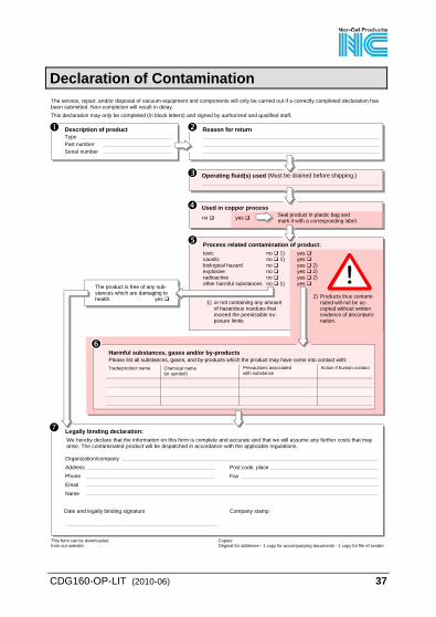
Declaration of Contamination The service, repair, and/or disposal of vacuum equipment and components will only be carried out if a correctly completed declaration has been submitted. Non-completion will result in delay.This declaration may only be completed (in block letters) and signed by authorized and qualified staff.
Description of product Type Part number Serial number
Reason for return
Legally binding declaration: We hereby declare that the information on this form is complete and accurate and that we will assume any further costs that may arise. The contaminated product will be dispatched in accordance with the applicable regulations.
Organization/company Address Post code, place Phone Fax Email Name
Date and legally binding signature Company stamp
Copies:Original for addresee - 1 copy for accompanying documents - 1 copy for file of sender
Operating fluid(s) used (Must be drained before shipping.)
Harmful substances, gases and/or by-productsPlease list all substances, gases, and by-products which the product may have come into contact with:Trade/product name Chemical name
(or symbol)Precautions associatedwith substance
Action if human contact
The product is free of any sub-stances which are damaging tohealth. yes
Used in copper processno yes Seal product in plastic bag and
mark it with a corresponding label.
This form can be downloaded from our website.
2) Products thus contami- nated will not be ac- cepted without written evidence of decontami- nation.
1) or not containing any amount of hazardous residues that exceed the permissible ex- posure limits
Process related contamination of product: toxic no 1) yes caustic no 1) yes biological hazard no yes 2) explosive no yes 2) radioactive no yes 2) other harmful substances no 1) yes
38 CDG160-OP-LIT (2010-06)
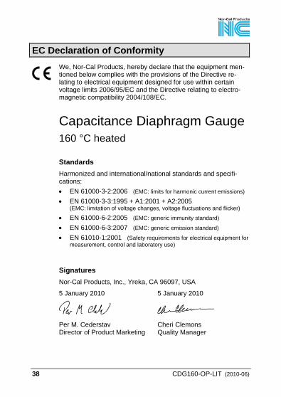
EC Declaration of Conformity We, Nor-Cal Products, hereby declare that the equipment men-tioned below complies with the provisions of the Directive re-lating to electrical equipment designed for use within certain voltage limits 2006/95/EC and the Directive relating to electro-magnetic compatibility 2004/108/EC.
Capacitance Diaphragm Gauge 160 °C heated
Standards Harmonized and international/national standards and specifi-cations: • EN 61000-3-2:2006 (EMC: limits for harmonic current emissions) • EN 61000-3-3:1995 + A1:2001 + A2:2005
(EMC: limitation of voltage changes, voltage fluctuations and flicker) • EN 61000-6-2:2005 (EMC: generic immunity standard) • EN 61000-6-3:2007 (EMC: generic emission standard) • EN 61010-1:2001 (Safety requirements for electrical equipment for
measurement, control and laboratory use)
Signatures Nor-Cal Products, Inc., Yreka, CA 96097, USA
5 January 2010 5 January 2010
Per M. Cederstav Director of Product Marketing
Cheri Clemons Quality Manager
CDG160-OP-LIT (2010-06) 39
Notes

1967 South Oregon St. Yreka, CA 96097, USA Tel: 800-824-4166 Fax: 530-842-9130
Original: English CDG160-OP-LIT (2009-11)
t nna53e1 www.n-c.com