Embed Size (px)
Citation preview
G-17, Bharat Industrial Estate, T. J. Road, Sewree (W), Mumbai - 400 015. INDIA.Sales Direct.: 022 -2 4156638, Tel. : 022-241224540, 24181649, Fax : 022 - 24149659Email : [email protected], Website : www.kusamelectrical.com,
All Specifications are subject to change without prior notice
Navin com/D:Sandeep Gupta/New Catlog Dec 2011/213HVD.cdr
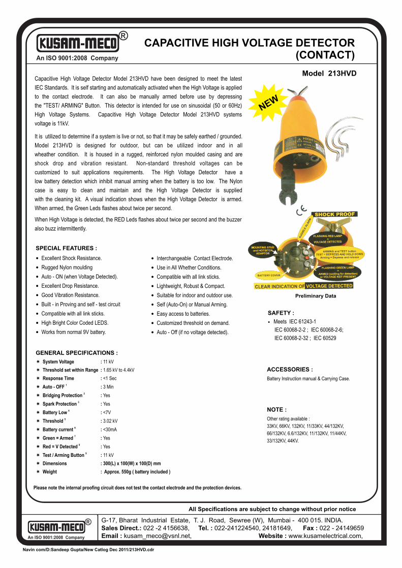
CAPACITIVE HIGH VOLTAGE DETECTOR (CONTACT)
Model 213HVD
IEC 60068-2-2 ; IEC 60068-2-6;
IEC 60068-2-32 ; IEC 60529
? Meets IEC 61243-1
SAFETY :
ACCESSORIES :
Battery Instruction manual & Carrying Case.
Capacitive High Voltage Detector Model 213HVD have been designed to meet the latest
IEC Standards. It is self starting and automatically activated when the High Voltage is applied
to the contact electrode. It can also be manually armed before use by depressing
the "TEST/ ARMING" Button. This detector is intended for use on sinusoidal (50 or 60Hz)
High Voltage Systems. Capacitive High Voltage Detector Model 213HVD systems
voltage is 11kV.
It is utilized to determine if a system is live or not, so that it may be safely earthed / grounded.
Model 213HVD is designed for outdoor, but can be utilized indoor and in all
wheather condition. It is housed in a rugged, reinforced nylon moulded casing and are
shock drop and vibration resistant. Non-standard threshold voltages can be
customized to suit applications requirements. The High Voltage Detector have a
low battery detection which inhibit manual arming when the battery is too low. The Nylon
case is easy to clean and maintain and the High Voltage Detector is supplied
with the cleaning kit. A visual indication shows when the High Voltage Detector is armed.
When armed, the Green Leds flashes about twice per second.
When High Voltage is detected, the RED Leds flashes about twice per second and the buzzer
also buzz intermittently.
SPECIAL FEATURES :
?
?
? Auto - ON (when Voltage Detected).
? Excellent Drop Resistance.
? Good Vibration Resistance.
? Built - in Proving and self - test circuit
? Compatible with all link sticks.
? High Bright Color Coded LEDS.
? Works from normal 9V battery.
Excellent Shock Resistance.
Rugged Nylon moulding
? Interchangeable Contact Electrode.
? Use in All Whether Conditions.
? Compatible with all link sticks.
? Lightweight, Robust & Compact.
? Suitable for indoor and outdoor use.
? Self (Auto-On) or Manual Arming.
? Easy access to batteries.
? Customized threshold on demand.
? Auto - Off (if no voltage detected).
Please note the internal proofing circuit does not test the contact electrode and the protection devices.
GENERAL SPECIFICATIONS :
í System Voltage : 11 kV
í Threshold set within Range : 1.65 kV to 4.4kV
í Response Time : <1 Sec1
í Auto - OFF : 3 Min2í Bridging Protection : Yes
3í Spark Protection : Yes4í Battery Low : <7V
5í Threshold : 3.02 kV6í Battery current : <30mA7í Green = Armed : Yes
8í Red = V Detected : Yes 9 í Test / Arming Button : 11 kV
í Dimensions : 300(L) x 100(W) x 100(D) mm
í Weight : Approx. 550g ( battery included )
NEW
NOTE :
Other rating available :
33KV, 66KV, 132KV, 11/33KV, 44/132KV,
66/132KV, 6.6/132KV, 11/132KV, 11/44KV,
33/132KV, 44KV.
Preliminary Data
An ISO 9001:2008 Company
®
An ISO 9001:2008 Company
®
G 17, Bharat Industrial Estate, T. J. Road, Sewree (W), Mumbai - 400 015. INDIA.
Sales Direct : (022) 24156638Tel. : (022) 24124540, 24181649. Fax : (022) 24149659
Email : [email protected] Website : www.kusamelectrical.com
www.kusam-meco.co.in
®MODEL - 213HVD
OPERATION MANUAL
®®
AN ISO 9001:2008 COMPANY
CAPACITIVE
HIGH VOLTAGE
DETECTOR
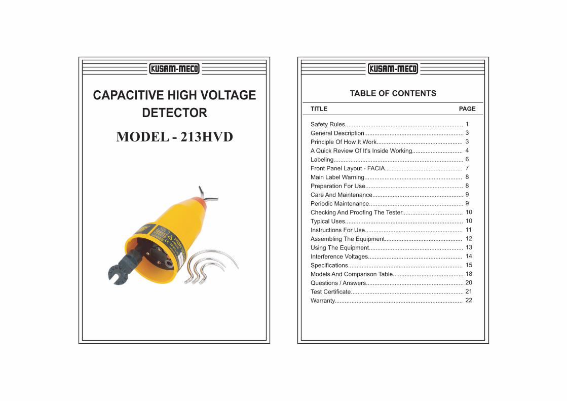
TABLE OF CONTENTS
PAGE
1
3
3
4
6
7
8
8
9
9
10
10
11
12
13
14
15
18
20
21
22
Safety Rules......................................................................
General Description...........................................................
Principle Of How It Work...................................................
A Quick Review Of It's Inside Working..............................
Labeling.............................................................................
Front Panel Layout - FACIA..............................................
Main Label Warning..........................................................
Preparation For Use..........................................................
Care And Maintenance......................................................
Periodic Maintenance........................................................
Checking And Proofing The Tester....................................
Typical Uses......................................................................
Instructions For Use..........................................................
Assembling The Equipment..............................................
Using The Equipment........................................................
Interference Voltages........................................................
Specifications....................................................................
Models And Comparison Table..........................................
Questions / Answers..........................................................
Test Certificate...................................................................
Warranty............................................................................
TITLE
MODEL - 213HVD
CAPACITIVE HIGH VOLTAGE
DETECTOR
01 02
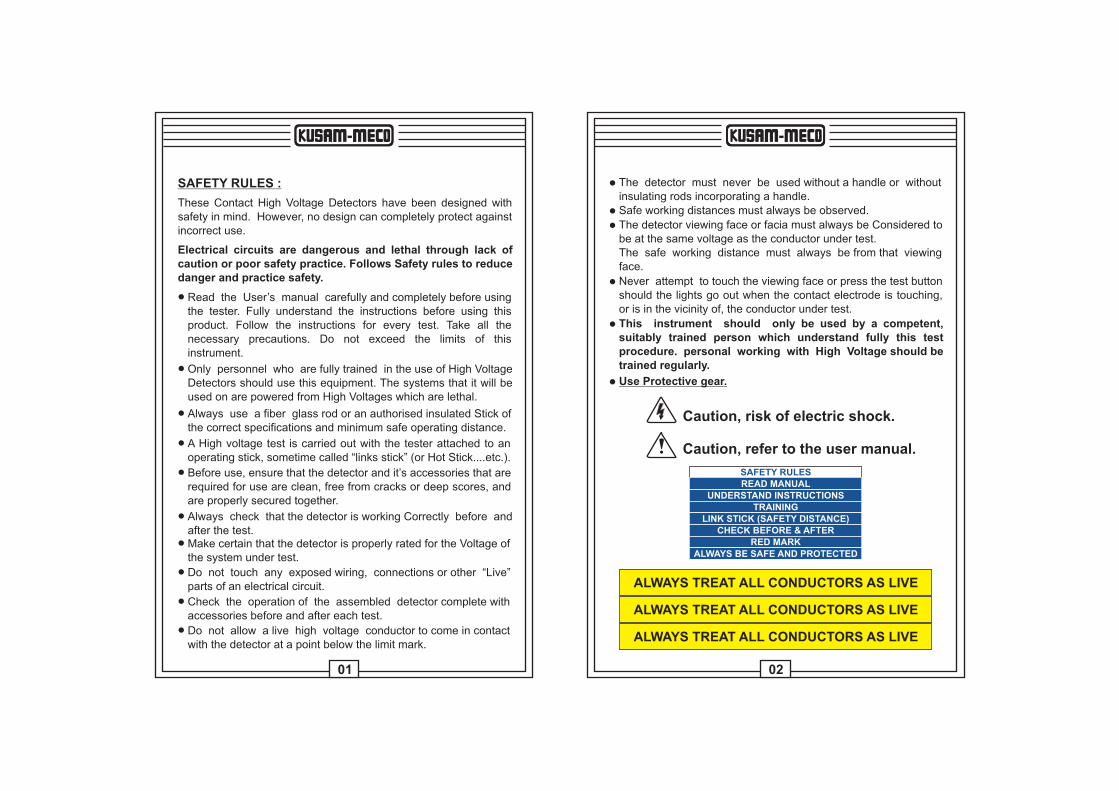
The detector must never be used without a handle or without insulating rods incorporating a handle.
l
Safe working distances must always be observed.l
The detector viewing face or facia must always be Considered tobe at the same voltage as the conductor under test.The safe working distance must always be from that viewing face.
l
SAFETY RULES :
These Contact High Voltage Detectors have been designed with safety in mind. However, no design can completely protect against incorrect use.
Electrical circuits are dangerous and lethal through lack ofcaution or poor safety practice. Follows Safety rules to reducedanger and practice safety.
Read the User’s manual carefully and completely before using the tester. Fully understand the instructions before using this product. Follow the instructions for every test. Take all the necessary precautions. Do not exceed the limits of this instrument.
l
Only personnel who are fully trained in the use of High VoltageDetectors should use this equipment. The systems that it will beused on are powered from High Voltages which are lethal.
l
Always use a fiber glass rod or an authorised insulated Stick of the correct specifications and minimum safe operating distance.
l
A High voltage test is carried out with the tester attached to an operating stick, sometime called “links stick” (or Hot Stick....etc.).
l
Before use, ensure that the detector and it’s accessories that arerequired for use are clean, free from cracks or deep scores, andare properly secured together.
l
Always check that the detector is working Correctly before and after the test.
l
Make certain that the detector is properly rated for the Voltage ofthe system under test.
l
Do not touch any exposed wiring, connections or other “Live” parts of an electrical circuit.
l
Check the operation of the assembled detector complete with accessories before and after each test.
l
Do not allow a live high voltage conductor to come in contact with the detector at a point below the limit mark.
l
Never attempt to touch the viewing face or press the test buttonshould the lights go out when the contact electrode is touching, or is in the vicinity of, the conductor under test.
l
This instrument should only be used by a competent, suitably trained person which understand fully this test procedure. personal working with High Voltage should be trained regularly.
l
Use Protective gear.l
Caution, risk of electric shock.
Caution, refer to the user manual.
SAFETY RULESREAD MANUAL
UNDERSTAND INSTRUCTIONS
TRAINING
LINK STICK (SAFETY DISTANCE)
CHECK BEFORE & AFTER
RED MARK
ALWAYS BE SAFE AND PROTECTED
ALWAYS TREAT ALL CONDUCTORS AS LIVE
ALWAYS TREAT ALL CONDUCTORS AS LIVE
ALWAYS TREAT ALL CONDUCTORS AS LIVE
03 04
GENERAL DESCRIPTION :
The range of capacitive high voltage detectors has been designedto meet the requirements of the latest International IEC standards(IEC61243-1).
They may be used indoors and outdoors in all weathers. The detectors are intended for use on high voltage systems but not in switchgear.
Models are available to cover a wide range of system voltages.
The function of the detector is to determine whether a conductor is energised or de-energised so that it may be safety earthed before commencing work.
PRINCIPLES OF HOW IT WORK :
A strong cone shaped nylon moulding houses the detector. The inner wall of the cone has a conductive screen coating to which the earthy parts of the circuit are connected.
This screen coating is capacitively coupled to the earth of the electric field and acts as a voltage divider with an internal sensing capacitor (The internal sensing capacitor is different from voltage range to voltage range
High voltage appearing at the electrode is divided down and the voltage across the sensing capacitor is proportional to the voltagebetween the electrode and earth.
This proportional signal voltage is fed to the electronic circuitry whose output drives an audible warning device and a system of indicating lamps.
The electronic circuitry has some scaling circuitry, an amplifier, rectifier and a comparator is set at the factory or set by an authorised calibration facility.
This range of capacitively coupled high Voltage Detectors uses multilayer boards with ground planes all over the board, elminatingfalse or noisy signals.
A QUICK OVERVIEW OF IT’S INSIDE WORKING :
ARMING :
The detector has a combined manual and a self arming mode.
Manual Arming Mode :
The ARMING/ TEST button is mounted on the front viewing face ofthe detector (the front viewing face of the detector has the buzzer, mounting stud (which has the attachment adaptor to the link stick),arming/test button and the lights (It’s also called the Facia).
When this button is depressed, the High Bright Red Leds flashestwice per second and the loud Buzzer (audible warning device) sounds also twice per second.
This is the display for voltage PRESENT.Pressing the button, activate an internal oscillator, and couple it to the input of the sensing circuitry, tough, simulating an external voltage.This is the display for voltage PRESENT.Pressing the button, activate an internal oscillator, and couple it to the input of the sensing circuitry, tough, simulating an external voltage. When the button is released the display changes to the High Bright Green flashing Leds (also twice per second).
This is the display for voltage NOT PRESENT and battery OK. Thedetector is then armed and ready for use. This armed condition lasts for about 3 minutes.
Arming the detector also functionally checks the internal circuitry but does not check the input protections or contactelectrode extension nor the internal sensing capacitor for anopen circuit condition. Use an external proofing unit for this.
Self Arming Mode :
In this mode of operation the detector automatically switches, ONwhen a High Voltage A.C. is applied to the contact electrode.
0605
INDICATING LIGHTS :
Two sets of High Bright Leds, one is Green, one is Red are available.
One is green for voltage NOT PRESENT and Battery OK and the other is red for voltage PRESENT.
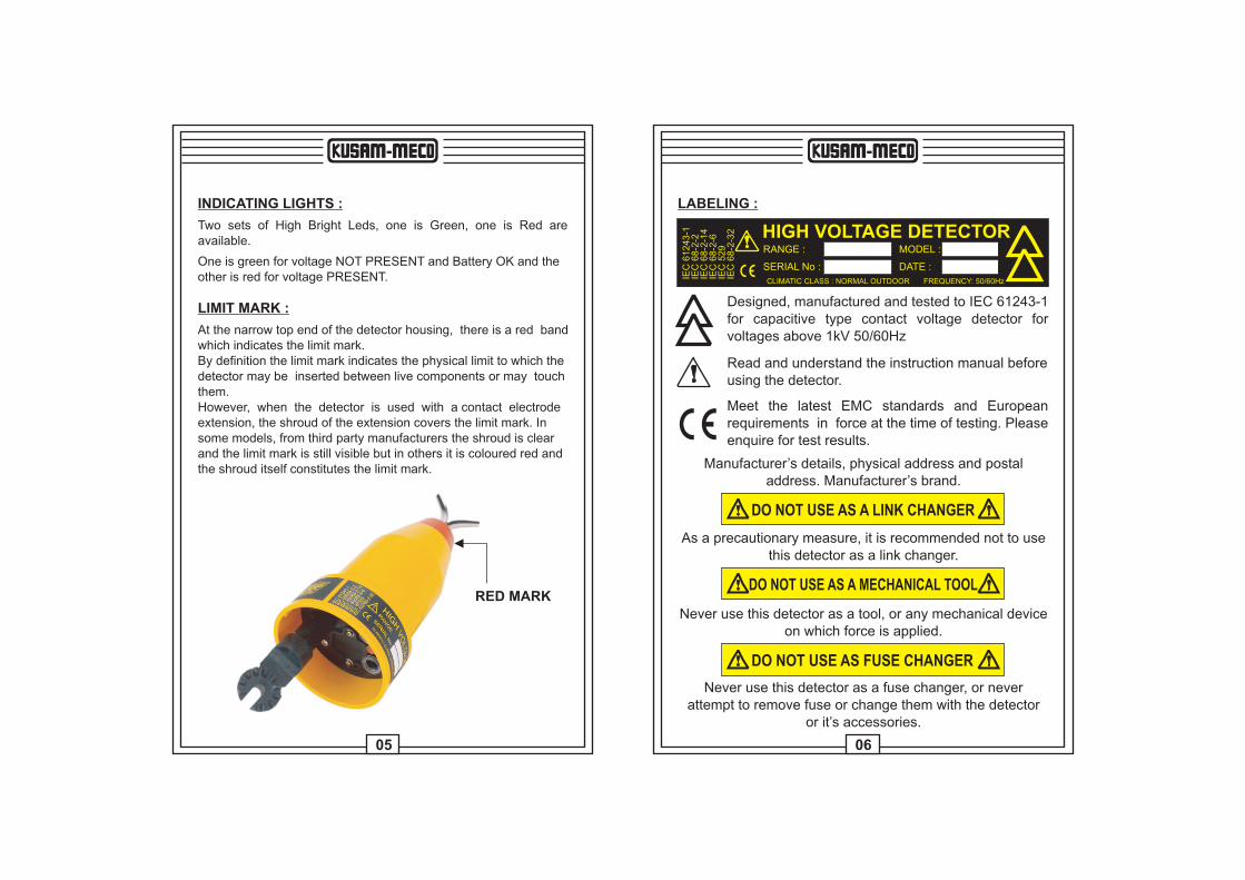
LIMIT MARK :
At the narrow top end of the detector housing, there is a red bandwhich indicates the limit mark.By definition the limit mark indicates the physical limit to which thedetector may be inserted between live components or may touchthem.However, when the detector is used with a contact electrode extension, the shroud of the extension covers the limit mark. In some models, from third party manufacturers the shroud is clearand the limit mark is still visible but in others it is coloured red and the shroud itself constitutes the limit mark.
RED MARK
LABELING :
HIGH VOLTAGE DETECTORRANGE : MODEL :
SERIAL No : DATE :CCLIMATIC CLASS : NORMAL OUTDOOR FREQUENCY: 50/60Hz
IEC
61243-1
IEC
68-2
-2IE
C 6
8-2
-14
IEC
68-2
-6IE
C 5
29
IEC
68-2
-32
Designed, manufactured and tested to IEC 61243-1for capacitive type contact voltage detector for voltages above 1kV 50/60Hz
Read and understand the instruction manual beforeusing the detector.
CMeet the latest EMC standards and European requirements in force at the time of testing. Pleaseenquire for test results.
Manufacturer’s details, physical address and postaladdress. Manufacturer’s brand.
DO NOT USE AS A LINK CHANGER
As a precautionary measure, it is recommended not to usethis detector as a link changer.
DO NOT USE AS A MECHANICAL TOOL
Never use this detector as a tool, or any mechanical deviceon which force is applied.
DO NOT USE AS FUSE CHANGER
Never use this detector as a fuse changer, or never attempt to remove fuse or change them with the detector
or it’s accessories.
08
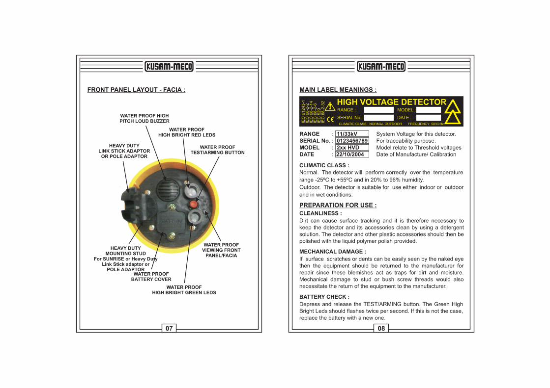
FRONT PANEL LAYOUT - FACIA :
WATER PROOF HIGHPITCH LOUD BUZZER
WATER PROOFHIGH BRIGHT RED LEDS
WATER PROOFTEST/ARMING BUTTON
HEAVY DUTYLINK STICK ADAPTOROR POLE ADAPTOR
HEAVY DUTYMOUNTING STUD
For SUNRISE or Heavy DutyLink Stick adaptor or
POLE ADAPTOR
WATER PROOFVIEWING FRONT
PANEL/FACIA
WATER PROOFHIGH BRIGHT GREEN LEDS
WATER PROOFBATTERY COVER
MAIN LABEL MEANINGS :
HIGH VOLTAGE DETECTORRANGE : MODEL :
SERIAL No : DATE :CCLIMATIC CLASS : NORMAL OUTDOOR FREQUENCY: 50/60Hz
IEC
61243-1
IEC
68-2
-2IE
C 6
8-2
-14
IEC
68-2
-6IE
C 5
29
IEC
68-2
-32
System Voltage for this detector.For traceability purpose.Model relate to Threshold voltagesDate of Manufacture/ Calibration
RANGE : 11/33kVSERIAL No. : 0123456789MODEL : 2xx HVDDATE : 22/10/2004
CLIMATIC CLASS :
Normal. The detector will perform correctly over the temperature
range -25ºC to +55ºC and in 20% to 96% humidity.
Outdoor. The detector is suitable for use either indoor or outdoor
and in wet conditions.
PREPARATION FOR USE :
CLEANLINESS :
Dirt can cause surface tracking and it is therefore necessary to keep the detector and its accessories clean by using a detergent solution. The detector and other plastic accessories should then bepolished with the liquid polymer polish provided.
MECHANICAL DAMAGE :
If surface scratches or dents can be easily seen by the naked eye then the equipment should be returned to the manufacturer for repair since these blemishes act as traps for dirt and moisture. Mechanical damage to stud or bush screw threads would also necessitate the return of the equipment to the manufacturer.
BATTERY CHECK :
Depress and release the TEST/ARMING button. The Green HighBright Leds should flashes twice per second. If this is not the case,replace the battery with a new one.
07
09 10
CARE AND MAINTENANCE :
STORAGE :
The detector and its accessories should be stored in the proprietary carrying case/bag when not in use. If the equipment is not going to be used for an appreciable length of time (one month or more) then it is a wise precaution to remove the battery. Remember to replace the battery when the equipment is used again. It’s advisable to replace the battery with a new one.
TRANSPORTING :
When the equipment is in transit it should be stored in it s carryingcase/ bag. Whilst the equipment has been designed for field use it should not be subjected to excessive bumps and shocks.
PERIODIC MAINTENANCE :
Battery Replacement :
It is expected that the battery life will be many months of normaluse. It is recommended therefore that the battery be replaced every six months whether or not it is found to be satisfactory whentesting/arming the detector.
The battery is located on the viewing facia of the detector. Its position is clearly indicated. Undo the two captive fixing screws and turn left anti-clockwise, remove the battery compartment cover. Slide out the battery and unclip the battery connector. Fit anew battery type 9V. Insert the battery into it’s place, the battery cover and it’s screws, making sure that the fixing screws are properly tightened (turn clockwise) to ensure a good water seal. There are no other replaceable or serviceable parts.
Recalibration and Proof Testing :
Every twelve months the detector and accessories should be rechecked. This should include checking the threshold voltage andvoltage proof testing of all the accessories. It is recommended that this rechecking be done by the manufacturer or it’s authorised appointed representative.
CHECKING AND PROOFING THE TESTER :
Checking :
Press the TEST/ARMING button to check the function of the internal circuitry and the condition of the battery.While depressing, the High Bright Red leds should flash about twice per second and the Buzzer should also sound twice persecond.When the button is released the High Bright Green leds will flashfor about 3 minutes.If the High Bright Green leds goes off immediately, replace the battery (see battery replacement).If the detector still does not arm correctly, then it is faulty and should be returned to the manufacturer for repair.
Proofing :
Using a known high voltage AC source.Arm the detector if necessary.Present the detector, armed if necessary, to a high voltage source,touching it with the contact electrode. The High Bright Red Leds will flash and the Buzzer alarm will sound, both, twice per second.
TYPICAL USES :
The main function of the detector is to determine whether a conductor is energised or de-energised so that it may be safely earthed before commencing work.The Detector is utilized to determine if a conductor is at a potential(conductor to earth) higher than the threshold level for which the detector is set.Once the conductor is at a potential higher than the set threshold, the detector will buzz and the red high bright leds will flashes twice per second.
11 12
INSTRUCTIONS FOR USE :
Visual Inspection :
Remove detector from its carry case then visually, inspect it.Feel it and cares by hand, and fingers.Everything must be smooth, just like a young women’s breast.Should it not be the case, send the detector to the factory to replace the case.
Cleaning the detector using a cloth :
Gently, clean the detector external body, using the supplied clothand fluid. Make sure all traces of dirts and unclean objects is removed.
Battery Check :
Depress the Red “TEST/ARM” button, then release. The High Bright Green Leds should flash twice per second if the battery is ok. If not, replace the battery.
Buzzer, and High Bright Red Light :
Depress and hold down the Red “TEST/ARM” button. The buzzerand the High Bright Red Leds should flash, both twice per secondif not, send the detector back to the factory for repairs.
Check the Adaptor :
Make sure the adaptor is not cracked and is tightly screwed ontothe detector. Should the adaptor show any type of crack, do not use it, as it could break while you are using it.Only use a good quality adaptor.
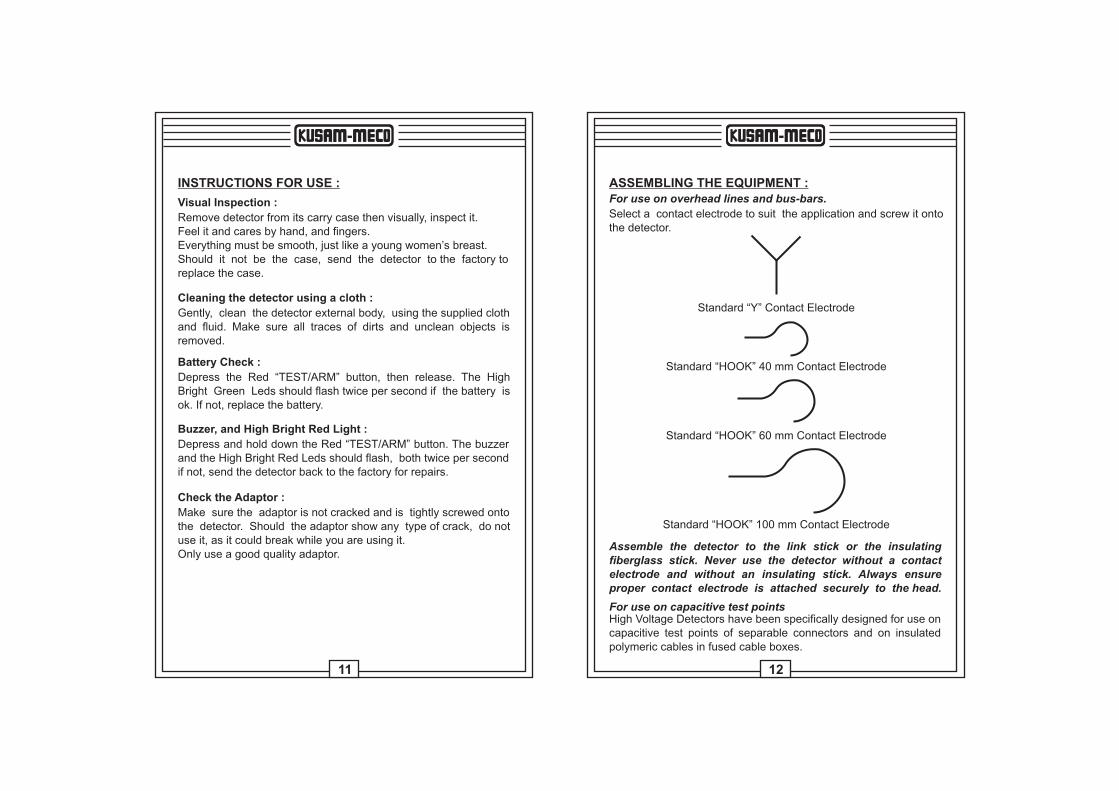
ASSEMBLING THE EQUIPMENT :For use on overhead lines and bus-bars.
Select a contact electrode to suit the application and screw it ontothe detector.
Standard “Y” Contact Electrode
Standard “HOOK” 40 mm Contact Electrode
Standard “HOOK” 60 mm Contact Electrode
Standard “HOOK” 100 mm Contact Electrode
Assemble the detector to the link stick or the insulating fiberglass stick. Never use the detector without a contact electrode and without an insulating stick. Always ensure proper contact electrode is attached securely to the head.
For use on capacitive test pointsHigh Voltage Detectors have been specifically designed for use oncapacitive test points of separable connectors and on insulated polymeric cables in fused cable boxes.
13 14
USING THE EQUIPMENT :Assemble the equipment as required Press the TEST/ARMING button to check the function of the internal circuitry and the condition of the battery. While depressing, the High Bright Red leds should flash about twice per second and the Buzzer should also sound twice per second. When the button is released the High Bright Green leds will flash for about 3 minutes. If the High Bright Green leds goes off immediately, replace the battery (seebattery replacement). If the detector still does not arm correctly,then it is faulty and should be returned to the manufacturer for repair.
Manual Arming :
Depress the TEST/ARMING button and the High Bright Red leds and the audible alarm (buzzer) will flash and the sound twice persecond and on releasing the alarming/test button the High BrightGreen leds will flash twice per second. The detector is now in itsarmed state ready for use. This condition lasts for about 3 minutes,unless contact with High Voltage is made (see Self Arming).
Self Arming :
Once the contact electrode is in Contact with High Voltage, thedetector will switch ON by itself, the High Bright Green leds will flash twice per second, unless the High Voltage is higher than the threshold, in which case, the High Bright Red leds will flash about twice per second and the Buzzer should also sound twice per second.
Proofing :
The complete assembled equipment should now be checked usinga known high voltage AC source. Arm the detector if necessary.Present the detector, armed if necessary, to a known high voltagesource, touching it with the contact electrode. The High Bright RedLeds will flash and the Buzzer alarm will sound, both, twice per second.
Testing :
Now present the detector to the conductor under test, touching it with the contact electrode. If the voltage on the conductor is greater than the threshold voltage of the detector, then the HighBright Red Leds will begin to flash and the audible alarm will sound, twice per second. This indicates that the conductor is live. The voltage present display will continue for as long as the detector contact electrode is in contact with the live conductor.If the voltage on the conductor is less than the threshold voltage ofdetector, then High Bright Red Leds and the audible alarm will notoperate. The High Bright Green leds will flash, twice per second.
INTERFERENCE VOLTAGES :In certain situations, due to the dimensions or configuration of theinstallation, electrical fields capable of affecting the indication of the detector may occur.Erroneous indication will only occur if the body of the detector is situated within such a field.Correct indication can be achieved by applying the detector to horizontal conductors away from bends or connections.Unambiguous indication of the detector depends upon the capacitance of the detector to earth being unaffected by other fields.
In-Phase Interference :
This occurs when the conductor under test is adjacent to anotherconductor whose voltage is in-phase.The field which is then generated can act as a screen between thedetector and earth, thereby reducing the effective capacitance of the detector to earth.This results in an increased threshold voltage which could mean that the detector will not indicate that a conductor is live.This results in an increased threshold voltage which could mean that the detector will not indicate that a conductor is live.
This increases the threshold voltage of the detector which may,therefore, not indicate. This is of course a dangerous situation.
15 16
Phase-Opposition Interference :
If a conductor under test has adjacent conductors which are in phase opposition, then erroneous indication can occur. For instance, if the conductor under test is earthed and the detector came close to a live conductor then it is possible that the detectorwill indicate that the conductor under test is live. This, however, can be seen as a fail safe condition, although it is incorrect.
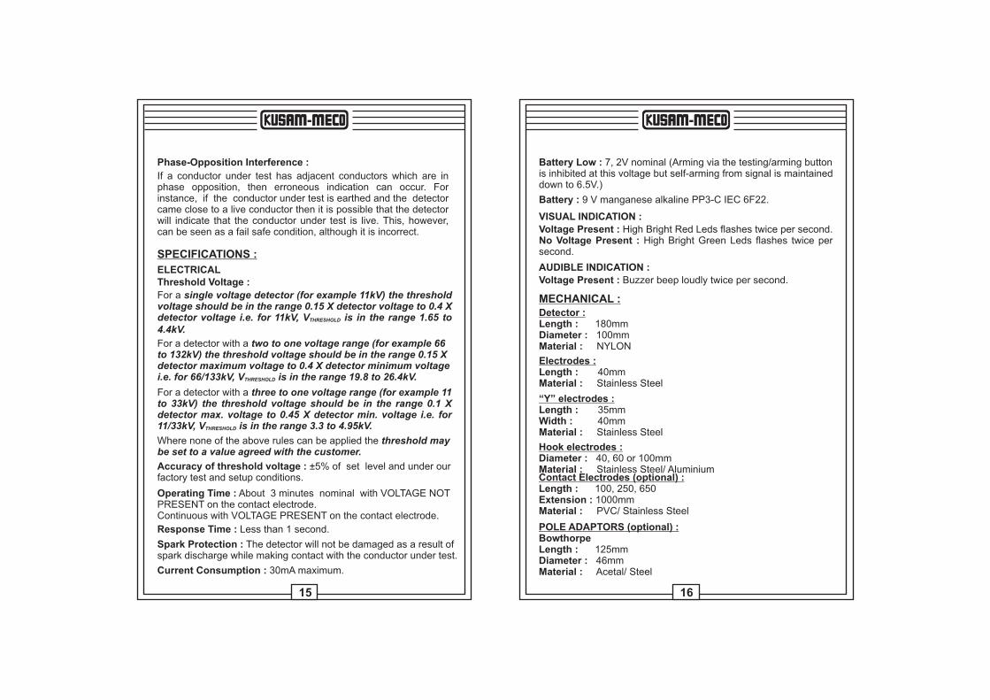
SPECIFICATIONS :
ELECTRICALThreshold Voltage :
For a single voltage detector (for example 11kV) the thresholdvoltage should be in the range 0.15 X detector voltage to 0.4 Xdetector voltage i.e. for 11kV, V is in the range 1.65 to THRESHOLD
4.4kV.
For a detector with a two to one voltage range (for example 66to 132kV) the threshold voltage should be in the range 0.15 Xdetector maximum voltage to 0.4 X detector minimum voltagei.e. for 66/133kV, V is in the range 19.8 to 26.4kV.THRESHOLD
For a detector with a three to one voltage range (for example 11to 33kV) the threshold voltage should be in the range 0.1 Xdetector max. voltage to 0.45 X detector min. voltage i.e. for 11/33kV, V is in the range 3.3 to 4.95kV.THRESHOLD
Where none of the above rules can be applied the threshold maybe set to a value agreed with the customer.
Accuracy of threshold voltage : ±5% of set level and under our factory test and setup conditions.
Operating Time : About 3 minutes nominal with VOLTAGE NOTPRESENT on the contact electrode.Continuous with VOLTAGE PRESENT on the contact electrode.
Response Time : Less than 1 second.
Spark Protection : The detector will not be damaged as a result ofspark discharge while making contact with the conductor under test.
Current Consumption : 30mA maximum.
Battery Low : 7, 2V nominal (Arming via the testing/arming buttonis inhibited at this voltage but self-arming from signal is maintaineddown to 6.5V.)
Battery : 9 V manganese alkaline PP3-C IEC 6F22.
VISUAL INDICATION :
Voltage Present : High Bright Red Leds flashes twice per second.No Voltage Present : High Bright Green Leds flashes twice per second.
AUDIBLE INDICATION :
Voltage Present : Buzzer beep loudly twice per second.
MECHANICAL :Detector :
Diameter : 100mmMaterial : NYLON
Length : 180mm
Electrodes :
Material : Stainless SteelLength : 40mm
“Y” electrodes :
Width : 40mmMaterial : Stainless Steel
Length : 35mm
Hook electrodes :
Material : Stainless Steel/ AluminiumDiameter : 40, 60 or 100mm
Contact Electrodes (optional) :
Material : PVC/ Stainless Steel
Length : 100, 250, 650Extension : 1000mm
POLE ADAPTORS (optional) :
Diameter : 46mmMaterial : Acetal/ Steel
BowthorpeLength : 125mm
17 18
Diameter : 27mmMaterial : Acetal/ Steel
Universal Star :Length : 95mm
Diameter : 25mmMaterial : Acetal/ Steel
Karl Pfisterer :Length : 85mm
Diameter : 45mmMaterial : Acetal/ Steel
Chance :Length : 85mm
Material : Fibreglass
Extension Poles :Length : 1200mm total
Vibration Resistance : In accordance with (IEC 68-2-6 Test Fc).The indicator and contact electrode are subjected to sinusoidalrectilinear vibrations in two perpendicular directions.
The frequency ranges from 10Hz to 500Hz and the duration of thesweep is set at 2 hours for each direction.
The test is considered passed if the detector shows no apparent mechanical deterioration.
Drop Resistance : In accordance with (IEC 68-2-32 Test Ed).The voltage detector is dropped from horiz. and vertical positionsfrom a height of 1m onto a test surface of concrete.
Shock Resistance : In accordance with (IEC 61243-1 Test 6.4.5.).Five mechanical shocks are performed on the most fragile parts ofthe indicator.The test is passed if the indicator shows no incipient fracture.
Cleaning Kit : Cloth and bottles of polymer liquid.
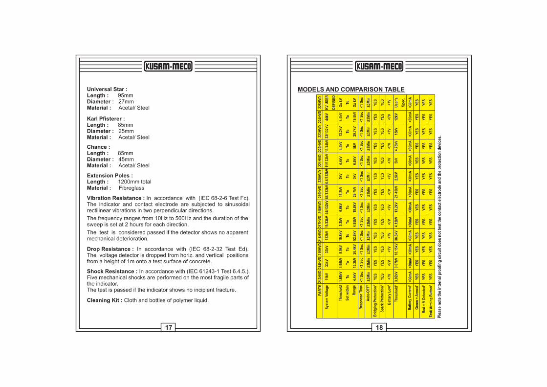
MODELS AND COMPARISON TABLE
PAR
T#
Sys
tem
Vo
ltag
e
Th
resh
old
Set
wit
hin
Ran
ge
Res
po
nse
Tim
e 1A
uto
-OF
F
2B
rid
gin
g P
rote
ctio
n
3S
par
k P
rote
ctio
n
4B
atte
ry L
ow
5T
hre
sho
ld
6B
atte
ry C
urr
ent 7
Gre
en =
Arm
ed
8R
ed =
V D
etec
ted
9Te
st/ A
rmin
g B
utt
on
223H
VD
33/1
32kV
13.2
kV
To
29.7
kV
<1 S
ec
±3M
in
YE
S
YE
S
<7V
15kV
<30m
A
YE
S
YE
S
YE
S
224H
VD
44kV
4.4k
V
To
19.8
kV
<1 S
ec
±3M
in
YE
S
YE
S
<7V
12kV
<30m
A
YE
S
YE
S
YE
S
225H
VD
KV
US
ER
DE
FIN
ED
Xx
kV
To
Xx
kV
<1 S
ec
±3M
in
YE
S
YE
S
<7V
Use
r’s
Sp
ec.
<30m
A
YE
S
YE
S
YE
S
214H
VD
33kV
4.95
kV
To
13.2
kV
<1 S
ec
±3M
in
YE
S
YE
S
<7V
9.07
kV
<30m
A
YE
S
YE
S
YE
S
213H
VD
11kV
1.65
kV
To
4.4k
V
<1 S
ec
±3M
in
YE
S
YE
S
<7V
3.02
kV
<30m
A
YE
S
YE
S
YE
S
215H
VD
33kV
9.9k
V
To
26.4
kV
<1 S
ec
±3M
in
YE
S
YE
S
<7V
18.1
5kV
<30m
A
YE
S
YE
S
YE
S
216H
VD
132k
V
19.8
kV
To
52.8
kV
<1 S
ec
±3M
in
YE
S
YE
S
<7V
36.3
kV
<30m
A
YE
S
YE
S
YE
S
217H
VD
11/3
3kV
3.3k
V
To
4.95
kV
<1 S
ec
±3M
in
YE
S
YE
S
<7V
4.12
kV
<30m
A
YE
S
YE
S
YE
S
218H
VD
44/1
32kV
6.6k
V
To
19.8
kV
<1 S
ec
±3M
in
YE
S
YE
S
<7V
13.2
kV
<30m
A
YE
S
YE
S
YE
S
219H
VD
66/1
32kV
13.2
kV
To
29.7
kV
<1 S
ec
±3M
in
YE
S
YE
S
<7V
21.4
5kV
<30m
A
YE
S
YE
S
YE
S
220H
VD
6.6/
132k
V
2kV
To 3kV
<1 S
ec
±3M
in
YE
S
YE
S
<7V
2.5k
V
<30m
A
YE
S
YE
S
YE
S
221H
VD
11/1
32kV
4.4k
V
To
6.6k
V
<1 S
ec
±3M
in
YE
S
YE
S
<7V
5kV
<30m
A
YE
S
YE
S
YE
S
222H
VD
11/4
4kV
4.4k
V
To 5kV
<1 S
ec
±3M
in
YE
S
YE
S
<7V
4.75
kV
<30m
A
YE
S
YE
S
YE
S
Ple
ase
no
te t
he
inte
rnal
pro
ofi
ng
cir
cuit
do
es n
ot
test
th
e co
nta
ct e
lect
rod
e an
d t
he
pro
tect
ion
dev
ices
.
19 20
1Auto-OFF = The auto-OFF timer is reset every time the contact electrode of the 2xx HVD touch a High Voltage or each time High Voltage is detected. The auto-off timer is also reset each time the device is armed and tested, using the front button.Auto-OFF timer is approximatively 3 minutes.
2Bridging Protection = The Detector and it’s accessories will not cause flashover between live parts of the installation or between live parts of the installation and earth/ground.
3Spark Protection = The Detector will not be damaged as a result of spark dischargewhile making contact with the conductor under test.
4Battery Low = When battery is low, the HVD will not stay armed after depressing the “TEST/ARMING” button, and green LED will not flashes. (The flashing green Light indicates the standby mode).
Do not use if the green Led does not flashes after depressing “TEST/
ARMING”. This indicate a low battery condition. Replace battery
immediately. DO NO OPERATE.
5Threshold =This is the optimum recommended Threshold to set the detection levelat which the detector show and sound an High Voltage Alarm. This is the recommended level at which the calibration laboratories must set the detector. In Factory, it is set withing a range, but optionally, it can be set to this threshold and a calibration certificate issued.
6Battery Current = This is the total current consumption taken from the battery whenthe buzzer sounds and Red Light lit (voltage detected mode). This is the worst case of current consumption.
7Green = Armed = The Green light flashes when the detector is armed and waiting for HV to be detected. This also mean that the battery is ok.
8Red = V Detected = The Red light flashes when High Voltage is detected. This happen when the voltage detected is higher than the threshold of that model (see tables).
9Test/Arming Button = This button is utilized to arm (turn ON) the detector. When thisbutton is pressed, and while pressing it, a internal proofing oscillator isconnected to the detector and simulate HV on the electrode. While the “TEST/ARMING” button is depressed, the Red light flashes and the buzzer sounds, indicating that the detector works properly. When releasing this button, the green light must flash, indicating the battery is ok, and the detector is in standby, waiting for detection.
Questions / Answers :
The Pole adaptor mounting stud is not seen in the case.Are you sure it’s not simply still attached onto the detector ?Many users keep it attached onto their detector, even after use.
I press “Test/Arming” button, but all the Leds Stays off and the detector looks dead!!!!The battery may not be present or is so low that nothing is happening. First, change the battery.
I press “Test/Arming” button, the High Bright Red Leds andthe Buzzer sound intermittently, but when I release the “Test/Arming” button, but all the Leds goes off and the detector looks dead!!!!The battery is low. Replace the battery with a new one.
The Detector is dirty. What can I use to clean it with, and how?In the case, should be a full bottle of cleaning material.
I can’t find the battery. Which battery must I buy, and what kind ?The battery is situated in the front panel. Remove the 2 screws first, then slowly and gently, remove the battery. Replace with any9V battery.
The body of the Detector is scratched. Is it dangerous ?Yes, it’s advised that if your detector has any trace of scratches, you can get a replacement casing. However, this operation can only done at the factory.
21 22
MUMBAI
TEST CERTIFICATE
CAPACITIVE HIGH VOLTAGE DETECTOR
This Test Certificate warrantees that the product has been
inspected and tested in accordance with the published
specifications.
The instrument has been calibrated by using equipment
which has already been calibrated to standards traceable
to national standards.
MODEL NO. ________________213HVD
SERIAL NO. ___________
DATE: ___________
ISO 9001REGISTERED
QC
PASS
KUSAM-MECO
WARRANTYEach “KUSAM-MECO” product is warranted to be free from defects in
material and workmanship under normal use & service. The warranty
period is one year (12 months) and begins from the date of despatch of
goods. In case any defect occurs in functioning of the instrument, under
proper use, within the warranty period, the same will be rectified by us
free of charges, provided the to and fro freight charges are borne by you.
This warranty extends only to the original buyer or end-user customer of a
“KUSAM-MECO” authorized dealer.
This warranty does not apply for damaged Ic’s, fuses, burnt PCB's,
disposable batteries, carrying case, test leads, or to any product which in
“KUSAM-MECO’s” opinion, has been misused, altered, neglected,
contaminated or damaged by accident or abnormal conditions of
operation or handling.
“KUSAM-MECO” authorized dealer shall extend this warranty on new
and unused products to end-user customers only but have no authority to
extend a greater or different warranty on behalf of “KUSAM-MECO”.
“KUSAM-MECO’s” warranty obligation is limited, at option, free of charge
repair, or replacement of a defective product which is returned to a
“KUSAM-MECO” authorized service center within the warranty period.
THIS WARRANTY IS BUYER’S SOLE AND EXCLUSIVE REMEDY AND
IS IN LIEU OF ALL OTHER WARRANTIES, EXPRESS OR IMPLIED,
INCLUDING BUT NOT LIMITED TO ANY IMPLIED WARRANTY OF
MERCHANTABILITY OR FITNESS FOR A PARTICULAR PURPOSE.
“KUSAM-MECO” SHALL NOT BE LIABLE FOR ANY SPECIAL,
INDIRECT, INCIDENTAL OR CONSEQUENTIAL DAMAGES OR
LOSSES, INCLUDING LOSS OF DATA, ARISING FROM ANY CAUSE
WHATSOEVER.
All transaction are subject to Mumbai Jurisdiction.