Embed Size (px)
Citation preview
Wang et al. Microsystems & Nanoengineering (2020) 6:73 Microsystems & Nanoengineeringhttps://doi.org/10.1038/s41378-020-0181-z www.nature.com/micronano
REV I EW ART ICLE Open Ac ce s s
Capacitive micromachined ultrasound transducersfor intravascular ultrasound imagingJiaqi Wang 1, Zhou Zheng1, Jasmine Chan1 and John T. W. Yeow1
AbstractIntravascular ultrasound (IVUS) is a burgeoning imaging technology that provides vital information for the diagnosis ofcoronary arterial diseases. A significant constituent that enables the IVUS system to attain high-resolution images is theultrasound transducer, which acts as both a transmitter that sends acoustic waves and a detector that receives thereturning signals. Being the most mature form of ultrasound transducer available in the market, piezoelectrictransducers have dominated the field of biomedical imaging. However, there are some drawbacks associated withusing the traditional piezoelectric ultrasound transducers such as difficulties in the fabrication of high-density arrays,which would aid in the acceleration of the imaging speed and alleviate motion artifact. The advent ofmicroelectromechanical system (MEMS) technology has brought about the development of micromachinedultrasound transducers that would help to address this issue. Apart from the advantage of being able to be fabricatedinto arrays with lesser complications, the image quality of IVUS can be further enhanced with the easy integration ofmicromachined ultrasound transducers with complementary metal-oxide-semiconductor (CMOS). This would aid inthe mitigation of parasitic capacitance, thereby improving the signal-to-noise. Currently, there are two commonlyinvestigated micromachined ultrasound transducers, piezoelectric micromachined ultrasound transducers (PMUTs)and capacitive micromachined ultrasound transducers (CMUTs). Currently, PMUTs face a significant challenge wherethe fabricated PMUTs do not function as per their design. Thus, CMUTs with different array configurations have beendeveloped for IVUS. In this paper, the different ultrasound transducers, including conventional-piezoelectrictransducers, PMUTs and CMUTs, are reviewed, and a summary of the recent progress of CMUTs for IVUS is presented.
IntroductionCoronary artery disease (CAD), also called coronary or
atherosclerotic heart disease, carries a high mortality rateworldwide. CAD arises from the accumulation of cho-lesterol and plaques on the arterial inner walls. Theseplaques slow down the flow of blood to the heart muscleby clogging the artery or by causing vascular functionalabnormality1. The golden standard to diagnose this dis-ease is invasive coronary angiography that can determinethe morphology of the blood vessels to visualize stenosis2.However, the view of this method is too limited to detectcomplex atherosclerotic situations because some lesionsare commonly not reflected in the luminal silhouettebefore they obstruct lumen, which makes it challenging
for the assessment of CAD progression and prevention3.To include the diagnosis more accurately, optical coher-ence tomography (OCT), photoacoustic endoscopic ima-ging and intravascular ultrasound (IVUS) have emerged.OCT is a noninvasive imaging technique that makes useof backscattered light, typically in the infrared range, toacquire live images at near-microscopic resolution(1–2mm)4. During the operating process of OCT, apartfrom a standard contrast flush to clear the blood column,an extra flush in combination with saline is sometimesadopted, but this may cause damage to kidney5. By con-trast, photoacoustic endoscopic relies on laser-inducedultrasound to provide images6,7. This method breaks theshackles of pure optical imaging that relies on ballisticphotons, allowing the sharp contrast of optical images aswell as the high-quality imaging at depths of about2 mm8–10. However, due to the inadequate imaging
© The Author(s) 2020OpenAccessThis article is licensedunder aCreativeCommonsAttribution 4.0 International License,whichpermits use, sharing, adaptation, distribution and reproductionin any medium or format, as long as you give appropriate credit to the original author(s) and the source, provide a link to the Creative Commons license, and indicate if
changesweremade. The images or other third partymaterial in this article are included in the article’s Creative Commons license, unless indicated otherwise in a credit line to thematerial. Ifmaterial is not included in the article’s Creative Commons license and your intended use is not permitted by statutory regulation or exceeds the permitted use, you will need to obtainpermission directly from the copyright holder. To view a copy of this license, visit http://creativecommons.org/licenses/by/4.0/.
Correspondence: John T. W. Yeow ([email protected])1Department of Systems Design Engineering, Faculty of Engineering,University of Waterloo, Waterloo, ON N2L 3G1, Canada
1234
5678
90():,;
1234
5678
90():,;
1234567890():,;
1234
5678
90():,;
resolution at larger depths, the photoacoustic probeneeds to be positioned near the targeted region11.Contrary to other techniques, IVUS is able to reach thepenetration depth of 4–8 mm inside the blood vesselwall12. For this system, the ultrasound probe emitssound waves that echo off the blood vessel walls andreturn to the system. Real-time signals with differentintensities are addressed and analyzed by the console todisplay a series of longitudinal tomographic images13–15.As a cardiovascular (CV) interventional approach, IVUScan build live and high-quality images inside the vesselwith minimal side effects16. In particular, IVUS is excep-tionally competitive in examining arterial wall archi-tecture and lesion morphology17. In this review, wemainly discuss the limitations and enhancement of IVUS,thereby enabling IVUS to provide more accurate infor-mation for physicians.Owing to the crucial role of offering imaging informa-
tion, different ultrasound transducers on the IVUS systemwill be presented. Currently, conventional-piezoelectric-based transducers are the most widely chosen because oftheir mature technology, but they specify an inherentlysmall bandwidth18. Besides, rigid piezoceramic materialsmatch a higher acoustic impedance when compared tohuman tissues18. Hence, an acoustic impedance matchinglayer akin to human tissues is added, but the idealthickness is usually tough to realize19. Furthermore, tofabricate high-frequency arrays, transducer elementsshould be packed tightly together. As a primary approachto fabricate conventional-piezoelectric transducers,mechanical dicing restricts the pitch dimensions andcauses the aliasing phenomenon20. Since catheters arefrequently used in minimally invasive surgery (MIS), thesize of the catheter is also a critical factor in reaching theproximity of the imaging objects. Presently, commerciallyavailable IVUS catheters are smaller than 6F (ca. 2.0 mm).With the advent of microelectromechanical systems(MEMS) technology21–24, micromachined ultrasoundtransducers can be constructed with a smaller size.Therefore, such transducers can be promising as medicalinterventional imaging tools. Piezoelectric micro-machined ultrasound transducers (PMUTs) share thefabrication strength of integrated circuits but still exhibitnarrow bandwidth25. When the center frequency increa-ses, the fabricated membrane of PMUTs becomes rela-tively thin and fragile26. This makes the fabricationprocess of PMUTs more challenging. The development ofMEMS technology also stimulates that of capacitivemicromachined ultrasound transducers (CMUTs) inmany areas, such as medical and therapeutic imaging27
and non-destructive testing28. Specifically, CMUTsdemonstrate numerous advantages in IVUS systems.Compared with conventional-piezoelectric transducers,CMUTs do not need an acoustic impedance matching
layer. Instead of mechanical dicing, photolithographytechnology is adopted to fabricate CMUTs29. This tech-nology is well suited for fabricating smaller elements andmanipulating high-density CMUT arrays30. More impor-tantly, the similarity of the fabrication technology ofcomplementary metal-on-semiconductor (CMOS) andCMUTs allows mutual integration to form CMUT-on-CMOS structure, which reduces parasitic capacitance andimproves the signal-to-noise (SNR)20.In this paper, different ultrasound transducers in IVUS
will be presented, and the development of IVUS withCMUTs will be discussed in detail. The paper is struc-tured as follows: the next chapter briefly introduces theIVUS catheter. Chapter 3 describes three different types ofan ultrasound transducer that are conventional-piezoelectric transducers, PMUTs, and CMUTs, fol-lowed by the recent progress of IVUS with CMUTs.Finally, the review concludes by giving an outlook onIVUS with CMUTs relying on the abovementionedsections.
Intravascular ultrasound catheterThe IVUS catheter is mounted with a miniature ultra-
sound transducer with a center frequency of20–40MHz31. Since the choice of frequency associateswith the resolution and penetration depth, there is atrade-off between these properties depending on differentdesign requirements32. In the practical situation,mechanical and solid-state catheters are frequently used.In the mechanical system, a motor outside the body isused for rotating the drive cable to control the transdu-cer33. The drive cable should be as flexible as possible, soto adjust for the curving vessel and accurately position thetransducer. For a rotary transducer, the aperture sizeshould also be smaller than the diameter of the catheter.Due to the mechanical binding and the inconsistentrotation of the transducers, nonuniform rotational dis-tortion (NURD) is inevitable and observed for both in vivobody tissues and ex vivo investigations34. Another dis-advantage is that shadow effects result in the blurring ofimages on account of the side guidewire. Solid-statecatheters address some of these issues. In the solid-statecatheter system, a wide range of small transducer arraysare mounted at the catheter tip around the cylinder, and across-sectional scan can be conducted by the ultrasonicbeam. With the guidewire arranged in the center of thelumen, shadow artifacts can be avoided. However, whentransducers are close to tissues, the overlapping trans-mitted pulses from tissues can produce adverse artifactscalled “ring-down artifacts”. The artifacts appear as brighthalos of variable thickness and can obscure the image35.According to different requirements, mechanical andsolid-state catheters can be selectively produced. Cur-rently, the solid-state catheter called “Eagle Eye Platinum
Wang et al. Microsystems & Nanoengineering (2020) 6:73 Page 2 of 13
ST” has been rolled out by Phillip Volcano, with thecenter frequency of 20MHz.In the following section, ultrasound transducers, the
core component to provide imaging information, will beintroduced in detail.
Ultrasound transducers in intravascularultrasoundUltrasound transducers play a crucial role in the per-
formance of the IVUS system as they can produce high-frequency sound waves and are able to offer real-timehigh-resolution Doppler imaging36. In this chapter,conventional-piezoelectric transducers, PMUTs andCMUTs in medical ultrasound imaging are presented.
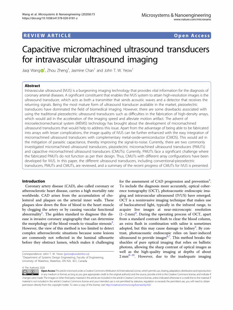
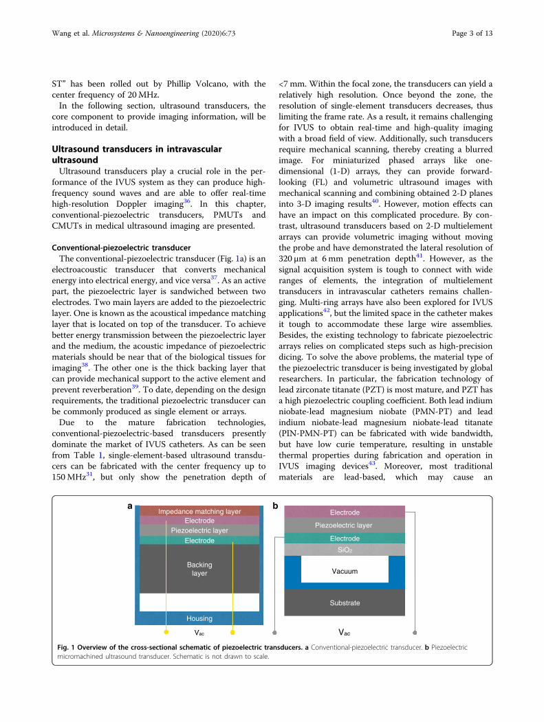
Conventional-piezoelectric transducerThe conventional-piezoelectric transducer (Fig. 1a) is an
electroacoustic transducer that converts mechanicalenergy into electrical energy, and vice versa37. As an activepart, the piezoelectric layer is sandwiched between twoelectrodes. Two main layers are added to the piezoelectriclayer. One is known as the acoustical impedance matchinglayer that is located on top of the transducer. To achievebetter energy transmission between the piezoelectric layerand the medium, the acoustic impedance of piezoelectricmaterials should be near that of the biological tissues forimaging38. The other one is the thick backing layer thatcan provide mechanical support to the active element andprevent reverberation39. To date, depending on the designrequirements, the traditional piezoelectric transducer canbe commonly produced as single element or arrays.Due to the mature fabrication technologies,
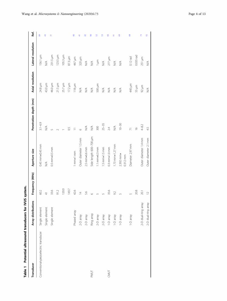
conventional-piezoelectric-based transducers presentlydominate the market of IVUS catheters. As can be seenfrom Table 1, single-element-based ultrasound transdu-cers can be fabricated with the center frequency up to150MHz31, but only show the penetration depth of
<7 mm. Within the focal zone, the transducers can yield arelatively high resolution. Once beyond the zone, theresolution of single-element transducers decreases, thuslimiting the frame rate. As a result, it remains challengingfor IVUS to obtain real-time and high-quality imagingwith a broad field of view. Additionally, such transducersrequire mechanical scanning, thereby creating a blurredimage. For miniaturized phased arrays like one-dimensional (1-D) arrays, they can provide forward-looking (FL) and volumetric ultrasound images withmechanical scanning and combining obtained 2-D planesinto 3-D imaging results40. However, motion effects canhave an impact on this complicated procedure. By con-trast, ultrasound transducers based on 2-D multielementarrays can provide volumetric imaging without movingthe probe and have demonstrated the lateral resolution of320 μm at 6mm penetration depth41. However, as thesignal acquisition system is tough to connect with wideranges of elements, the integration of multielementtransducers in intravascular catheters remains challen-ging. Multi-ring arrays have also been explored for IVUSapplications42, but the limited space in the catheter makesit tough to accommodate these large wire assemblies.Besides, the existing technology to fabricate piezoelectricarrays relies on complicated steps such as high-precisiondicing. To solve the above problems, the material type ofthe piezoelectric transducer is being investigated by globalresearchers. In particular, the fabrication technology oflead zirconate titanate (PZT) is most mature, and PZT hasa high piezoelectric coupling coefficient. Both lead indiumniobate-lead magnesium niobate (PMN-PT) and leadindium niobate-lead magnesium niobate-lead titanate(PIN-PMN-PT) can be fabricated with wide bandwidth,but have low curie temperature, resulting in unstablethermal properties during fabrication and operation inIVUS imaging devices43. Moreover, most traditionalmaterials are lead-based, which may cause an
Piezoelectric layer
Vacuum
Substrate
Electrode
Electrode
SiO2
VacVac
Piezoelectric layer
Backinglayer
Electrode
Electrode
Impedance matching layer
Housing
a b
Fig. 1 Overview of the cross-sectional schematic of piezoelectric transducers. a Conventional-piezoelectric transducer. b Piezoelectricmicromachined ultrasound transducer. Schematic is not drawn to scale.
Wang et al. Microsystems & Nanoengineering (2020) 6:73 Page 3 of 13
Table
1Po
tential
ultrasou
ndtran
sduc
ersforIVUSsystem
.
Tran
sduc
erArray
distributions
Freq
uenc
y(M
Hz)
Aperture
size
Pene
trationdep
th(m
m)
Axial
resolution
Lateralresolution
Ref.
Con
ventional-p
iezoelectrictransducer
Sing
leelem
ent
60.2
0.45
mm∗0.45mm
3.1–6.9
24.8μm
156.1μm
89
Sing
leelem
ent
41N/A
N/A
43.0μm
N/A
43
Sing
leelem
ent
33.6
0.5mm∗0.5mm
546.0μm
231.5μm
31
91.2
221.5μm
123.5μm
120.0
125.7μm
105.3μm
149.7
0.5
17.2μm
87.3μm
Phased
array
42.6
1mm∗1
mm
11118μm
467μm
40
2-Darray
14Outer
diam
eter
1.5mm
6N/A
320μm
41
2-Darray
5.6
2.5mm∗6.6mm
N/A
N/A
N/A
42
PMUT
Ring
array
6Side
leng
th600–700μm
N/A
N/A
N/A
90
2-Darray
51.1mm∗6.3mm
300
500μm
1μm
52
2-Darray
51.5mm∗1.5mm
25–35
N/A
N/A
53
CMUT
1-Darray
35.6
0.3mm∗1.0mm
2.4
N/A
277μm
66
1-Darray
9.2
1.73
mm∗1.27mm
N/A
N/A
N/A
91
1-Darray
52.392mm∗
0.312mm
10–30
N/A
N/A
69
1-Darray
5Diameter
2.97
mm
71440μm
0.12
rad
68
20.8
1655
μm
0.035rad
2-Ddu
al-ringarray
20.1
Outer
diam
eter
1.4mm
4–8.2
92μm
251μm
74
2-Ddu
al-ringarray
12Outer
diam
eter
2.1mm
4.5
N/A
N/A
92
Wang et al. Microsystems & Nanoengineering (2020) 6:73 Page 4 of 13
environmental hazard and may be harmful to humanhealth. Although some piezoelectric materials withoutlead have been confirmed, the inferior acoustic andelectrical features of these novel materials make it difficultto surpass conventional lead-based materials44,45. Due tothe development of MEMS, piezoelectric-materials-basedmicromachined ultrasound transducers have attractedmuch attention.
Piezoelectric micromachined ultrasound transducerPMUTs have solved some of the issues that traditional
transducers cannot address—specifically, the integrationwith application-specific integrated circuits (ASICs).However, the fabrication of PMUTs remains a challengebecause the center frequency is sensitive to the residualstress of the active layer. With the increase of frequency,the fabricated membrane tends to be as thin as possible,which may result in membrane cracking during the fab-rication process. Additionally, practical PMUTs usuallyperforms worse than their theoretical design. Figure 1bshows the cross-sectional structure of PMUTs. A PMUTis based on a piezoelectric membrane from a series ofpatterned layer stack that is deposited on a silicon wafer.The membrane is driven by applying an excitation voltagebetween the top and bottom electrodes. Transverse stressin the active piezoelectric layer is formed from the appliedelectric field, which causes the membrane to displace out-of-plane, generating a pressure wave in the outer med-ium46. Different piezoelectric materials have been pro-duced in the PMUTs, such as PZT47, zinc oxide (ZnO)48,and aluminum nitride (AlN)49. With a low operatingfrequency of kHz range, ZnO-based PMUTs are not sui-table for IVUS probes that usually operate in MHzrange50.PMUTs show some advantages in the catheterization,
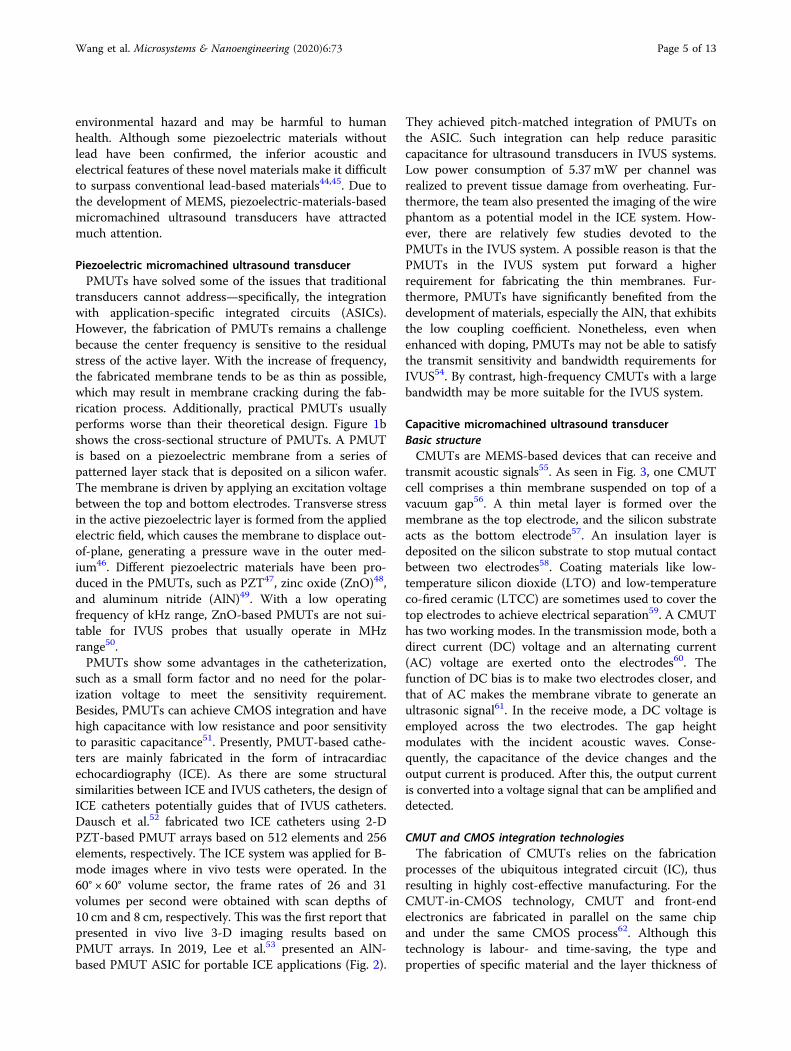
such as a small form factor and no need for the polar-ization voltage to meet the sensitivity requirement.Besides, PMUTs can achieve CMOS integration and havehigh capacitance with low resistance and poor sensitivityto parasitic capacitance51. Presently, PMUT-based cathe-ters are mainly fabricated in the form of intracardiacechocardiography (ICE). As there are some structuralsimilarities between ICE and IVUS catheters, the design ofICE catheters potentially guides that of IVUS catheters.Dausch et al.52 fabricated two ICE catheters using 2-DPZT-based PMUT arrays based on 512 elements and 256elements, respectively. The ICE system was applied for B-mode images where in vivo tests were operated. In the60° × 60° volume sector, the frame rates of 26 and 31volumes per second were obtained with scan depths of10 cm and 8 cm, respectively. This was the first report thatpresented in vivo live 3-D imaging results based onPMUT arrays. In 2019, Lee et al.53 presented an AlN-based PMUT ASIC for portable ICE applications (Fig. 2).
They achieved pitch-matched integration of PMUTs onthe ASIC. Such integration can help reduce parasiticcapacitance for ultrasound transducers in IVUS systems.Low power consumption of 5.37 mW per channel wasrealized to prevent tissue damage from overheating. Fur-thermore, the team also presented the imaging of the wirephantom as a potential model in the ICE system. How-ever, there are relatively few studies devoted to thePMUTs in the IVUS system. A possible reason is that thePMUTs in the IVUS system put forward a higherrequirement for fabricating the thin membranes. Fur-thermore, PMUTs have significantly benefited from thedevelopment of materials, especially the AlN, that exhibitsthe low coupling coefficient. Nonetheless, even whenenhanced with doping, PMUTs may not be able to satisfythe transmit sensitivity and bandwidth requirements forIVUS54. By contrast, high-frequency CMUTs with a largebandwidth may be more suitable for the IVUS system.
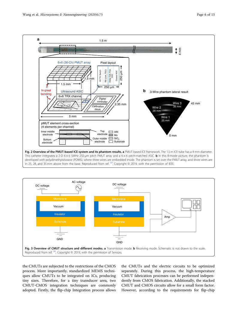
Capacitive micromachined ultrasound transducerBasic structureCMUTs are MEMS-based devices that can receive and
transmit acoustic signals55. As seen in Fig. 3, one CMUTcell comprises a thin membrane suspended on top of avacuum gap56. A thin metal layer is formed over themembrane as the top electrode, and the silicon substrateacts as the bottom electrode57. An insulation layer isdeposited on the silicon substrate to stop mutual contactbetween two electrodes58. Coating materials like low-temperature silicon dioxide (LTO) and low-temperatureco-fired ceramic (LTCC) are sometimes used to cover thetop electrodes to achieve electrical separation59. A CMUThas two working modes. In the transmission mode, both adirect current (DC) voltage and an alternating current(AC) voltage are exerted onto the electrodes60. Thefunction of DC bias is to make two electrodes closer, andthat of AC makes the membrane vibrate to generate anultrasonic signal61. In the receive mode, a DC voltage isemployed across the two electrodes. The gap heightmodulates with the incident acoustic waves. Conse-quently, the capacitance of the device changes and theoutput current is produced. After this, the output currentis converted into a voltage signal that can be amplified anddetected.
CMUT and CMOS integration technologiesThe fabrication of CMUTs relies on the fabrication
processes of the ubiquitous integrated circuit (IC), thusresulting in highly cost-effective manufacturing. For theCMUT-in-CMOS technology, CMUT and front-endelectronics are fabricated in parallel on the same chipand under the same CMOS process62. Although thistechnology is labour- and time-saving, the type andproperties of specific material and the layer thickness of
Wang et al. Microsystems & Nanoengineering (2020) 6:73 Page 5 of 13
the CMUTs are subjected to the restrictions of the CMOSprocess. More importantly, standardized MEMS techni-ques allow CMUTs to be integrated on ICs, producingtiny sizes. Therefore, for a tiny transducer area, twoCMUT-CMOS integration techniques are commonlyadopted. Firstly, the flip-chip Integration process allows
the CMUTs and the electric circuits to be optimizedseparately. During this process, the high-temperatureCMUT fabrication processes can be performed indepen-dently from CMOS fabrication. Additionally, the stackedCMUT and CMOS circuits allow for a small form factor.However, according to the requirements for flip-chip
DC voltageAC voltage
Membrane
Insulator
Vacuum
GND
Substrate
Membrane
Insulator
Vacuum
Substrate
GND
DC voltage
Amp
Fig. 3 Overview of CMUT structure and different modes. a Transmission mode. b Receiving mode. Schematic is not drawn to the scale.Reproduced from ref. 58, Copyright © 2019, with the permission of Sensors.
a
b
1.5 m
1.5 mm
1.5 mm 250
μm
250 μm
pMUT element cross-section(4 elements per channel)
Inner middleelectrode
Bottomelectrode
Topelectrode
Outer middleelectrode
AlNMoSiO2Substrate
4 m
m
In-pixelbonding
5 mm
2.35 mm
Digitalcontroller
Calibrationblock
6×6 TRX channel
Pixel layout6×6 (36-Ch) PMUT array
Ultrasound ASIC 3-Wire phantom lateral result
HV
TX
, Sw
itch
RX
(LN
A, T
GC
)
Del
ay C
ell,
Fin
eA
DC
Coa
rse
AD
C
Wire 335 mmWire 2
28 mm
Wire 125 mm
45 mm
0 mm
Fig. 2 Overview of the PMUT-based ICE system and its phantom results. a PMUT-based ICE framework. The 1.5 m ICE tube has a 4 mm diameter.This catheter integrates a 2-D 6 × 6 5MHz 250 μm pitch PMUT array and a 6 × 6 pitch-matched ASIC. b In this B-mode picture, the phantom isdeveloped with polydimethylsiloxane (PDMS), where three wires are embedded inside. The phantom is set over the PMUT array, and three wires arein 25, 28, and 35mm above from the base. Reproduced from ref. 53, Copyright © 2019, with the permission of IEEE.
Wang et al. Microsystems & Nanoengineering (2020) 6:73 Page 6 of 13
bonding, the CMUT design must consider through-wafervias. This means that both the top and bottom electrodescan be accessed by the bonding pads at the bottom of thewafer63. As a result, this method is complex. By contrast,the CMUT-on-CMOS process is a more cost-efficient anduseful method. For this process, CMUT is fabricated ontop of the CMOS electronic circuits, resulting in a smallin-plane area and minimal parasitic capacitance caused byelectronic traces and interfaces. The main challenge ofthis technique is that the high fabrication temperature ofCMUTs may cause damage to the electronics. However,due to the comprehensive research in low-temperaturefabrication processes64, CMUT-on-CMOS remains adesirable technology, especially in IVUS systems.
Array distributionsIn consideration of the convenience for physicians,
IVUS imaging catheters are designed with side-looking(SL) and FL functions. SL characteristic is useful indetermining the relative position of the blood vessels, andFL is helpful to offer volumetric real-time images inspecific vessels that are nearly blocked65. To achieveabove functions, several configurations of CMUT arraysare constructed, mainly phased arrays, ring arrays, andcylindrical arrays.
Phased CMUT arrayPhased CMUT arrays contain multiple individual ele-
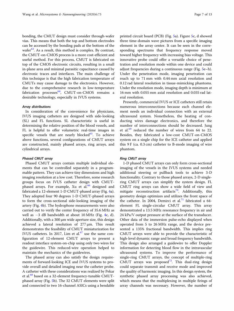
ments that can be controlled separately in a program-mable pattern. They can achieve tiny dimensions and highimaging resolution at a low cost. Therefore, some researchgroups focus on IVUS catheter design with CMUT-phased arrays. For example, Xu et al.66 designed andfabricated a 12-element 1-D CMUT-phased array (Fig. 4a).They adopted four 90 degrees 1-D CMUT-phased arraysto form the cross-sectional side-looking imaging of theartery (Fig. 4b). The hydrophone measurements were alsocarried out to verify the center frequency of 35.6MHz aswell as −3 dB bandwidth at about 10MHz (Fig. 4c, d).Additionally, with a 300 μm wide aperture size, this designachieved a lateral resolution of 277 μm. This resultdemonstrates the feasibility of CMUT miniaturization forIVUS catheters. In 2017, Lim et al.67 use the same con-figuration of 12-element CMUT arrays to present areadout interface system-on-chip using only two wires forthe guidewire. This reduced-wire operation helped tomaintain the mechanics of the guidewires.The phased array can also satisfy the design require-
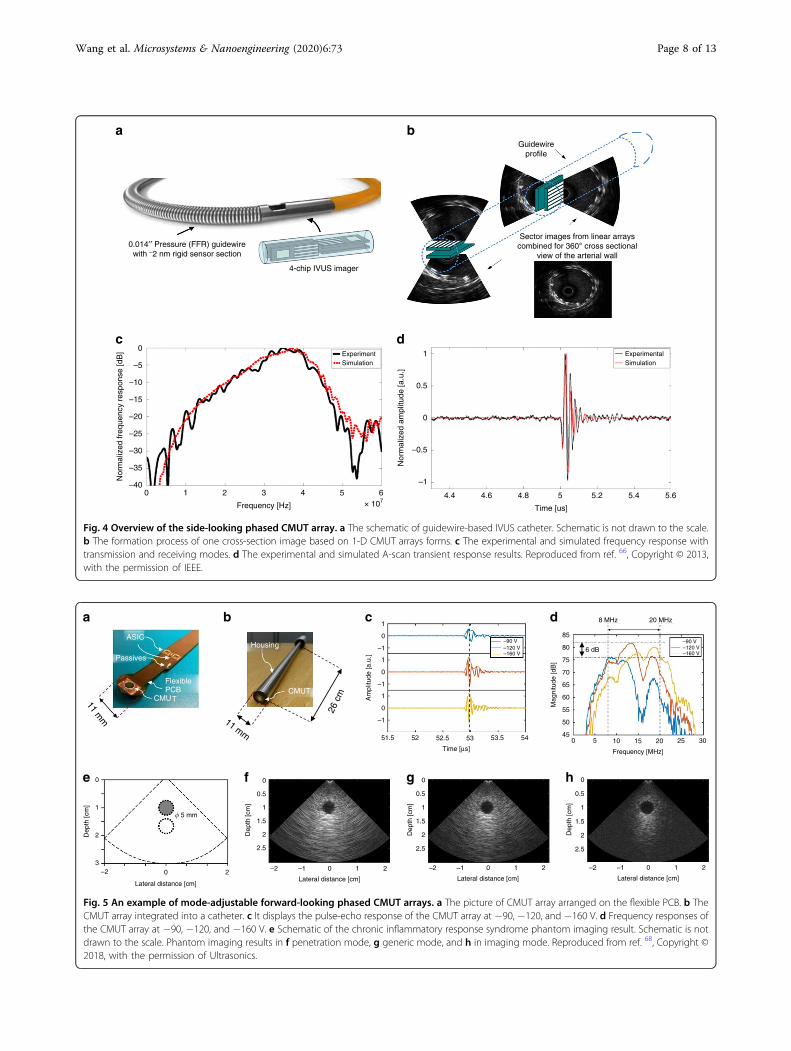
ments of forward-looking ICE and IVUS systems to pro-vide overall and detailed imaging near the catheter probe.A catheter with these considerations was realized by Pekaret al.68 based on a 32-element frequency-tunable CMUT-phased array (Fig. 5b). The 32 CMUT elements were splitand connected to two 16-channel ASICs using a bendable
printed circuit board (PCB) (Fig. 5a). Figure 5c, d showedthree time-domain wave pictures from a specific imagingelement in the array center. It can be seen in the corre-sponding spectrums that frequency response movedtoward higher frequency with increasing bias voltage. Thisinnovative probe could offer a versatile choice of pene-tration and resolution mode within one device and couldadjust frequencies during a continuous range (Fig. 5e–h).Under the penetration mode, imaging penetration canreach up to 71mm with 0.44 mm axial resolution and0.12 rad lateral resolution in tissue-mimicking phantoms.Under the resolution mode, imaging depth is minimum at16mm with 0.055 mm axial resolution and 0.035 rad lat-eral resolution.Presently, commercial IVUS or ICE catheters still retain
numerous interconnections because each channel ele-ment needs an individual connection with an externalultrasound system. Nonetheless, the heating of con-ducting wires damage electronics, and therefore thenumber of interconnections should be decreased. Junget al.69 reduced the number of wires from 64 to 22.Besides, they fabricated a low-cost CMUT-on-CMOSsystem on a single chip for the ICE catheter and appliedthis 9 F (ca. 0.3 cm) catheter to B-mode imaging of wirephantom.
Ring CMUT array1-D phased CMUT arrays can only form cross-sectional
imaging of the vessels in the IVUS systems and neededadditional steering or pullback tools to achieve 3-Dfunctionality. Contrary to those phased arrays, 2-D single-ring CMUT arrays can simplify the system design. FLCMUT ring arrays can show a wide field of view andmitigate reconstruction artifacts70. Additionally, thisgeometry design optimizes and utilizes the front space ofthe catheter. In 2004, Demirci et al.71 fabricated a 64-element FL single-circular CMUT array. This arraydemonstrated a 13.5MHz resonance frequency in air and24 kPa/V output pressure at the surface of the transducer.Other data of the immersion pulse-echo displayed whenoperated from 5 to 26MHz range, and the device pre-sented a 135% fractional bandwidth. This implies ringCMUT arrays were able to provide the characteristic ofhigh-level dynamic range and broad frequency bandwidth.This design also arranged a guidewire to offer Dopplerinformation for detecting blood flow in the intravascularultrasound systems. To improve the performance ofsingle-ring CMUT arrays, the concept of multiple-ringCMUT arrays was proposed72. This dual-ring designcould separate transmit and receive mode and improvedthe quality of harmonic imaging. In this design system, thesynthetic phased array processing was also achieved,which means that the multiplexing in multiple firings ofarray channels was necessary. However, the number of
Wang et al. Microsystems & Nanoengineering (2020) 6:73 Page 7 of 13
a
0.014′′ Pressure (FFR) guidewirewith ~2 nm rigid sensor section
4-chip IVUS imager
0
–5
–10
–15
Nor
mal
ized
freq
uenc
y re
spon
se [d
B]
Nor
mal
ized
am
plitu
de [a
.u.]
–20
–25
–30
–35
–400 1 2 3
Frequency [Hz]
4 5 6 4.4
1
0.5
ExperimentSimulation
0
–0.5
–1
4.6 4.8 5
Time [us]
5.2 5.4 5.6× 10⁷
b
c d
Sector images from linear arrayscombined for 360° cross sectional
view of the arterial wall
Guidewireprofile
ExperimentalSimulation
Fig. 4 Overview of the side-looking phased CMUT array. a The schematic of guidewire-based IVUS catheter. Schematic is not drawn to the scale.b The formation process of one cross-section image based on 1-D CMUT arrays forms. c The experimental and simulated frequency response withtransmission and receiving modes. d The experimental and simulated A-scan transient response results. Reproduced from ref. 66, Copyright © 2013,with the permission of IEEE.
b c da
e f g h
1
0
–1
1
0
–1
1
0
–1
85
80
75
70
65
60
55
50
450 5 10 15 20 25 30
Frequency [MHz]
8 MHz 20 MHz
6 dB
Mag
nitu
de [d
B]
51.5 52 52.5 53 53.5 54
Time [µs]
Am
plitu
de [a
.u.]
0
0.5
1
1.5
2
2.5
–2 –1 0 1 2
Lateral distance [cm]–2 0 2
Lateral distance [cm]
0
11 mm 11 mm
26 c
m
1
2
3
Dep
th [c
m]
Dep
th [c
m]
–90 V–120 V–160 V
ASIC
Passives
FlexiblePCB
CMUT
Housing
CMUT
–2 –1 0 1 2
Lateral distance [cm]
–2 –1 0 1 2
Lateral distance [cm]
0
0.5
1
1.5
2
2.5
Dep
th [c
m]
0
0.5
1
1.5
2
2.5
Dep
th [c
m]
–90 V–120 V–160 V
� 5 mm
Fig. 5 An example of mode-adjustable forward-looking phased CMUT arrays. a The picture of CMUT array arranged on the flexible PCB. b TheCMUT array integrated into a catheter. c It displays the pulse-echo response of the CMUT array at −90, −120, and −160 V. d Frequency responses ofthe CMUT array at −90, −120, and −160 V. e Schematic of the chronic inflammatory response syndrome phantom imaging result. Schematic is notdrawn to the scale. Phantom imaging results in f penetration mode, g generic mode, and h in imaging mode. Reproduced from ref. 68, Copyright ©2018, with the permission of Ultrasonics.
Wang et al. Microsystems & Nanoengineering (2020) 6:73 Page 8 of 13
firings should be reduced to realize a high frame rate andmitigate the motion artifacts73.Ring CMUT arrays can also be achieved on a single
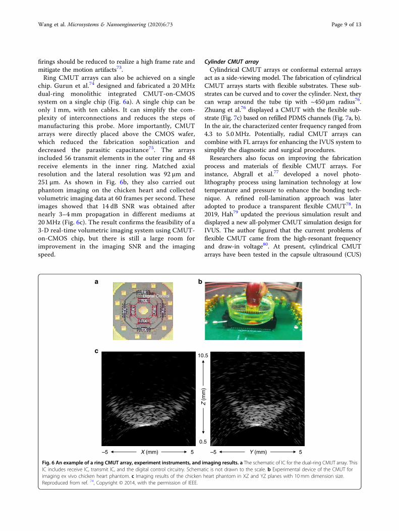
chip. Gurun et al.74 designed and fabricated a 20 MHzdual-ring monolithic integrated CMUT-on-CMOSsystem on a single chip (Fig. 6a). A single chip can beonly 1 mm, with ten cables. It can simplify the com-plexity of interconnections and reduces the steps ofmanufacturing this probe. More importantly, CMUTarrays were directly placed above the CMOS wafer,which reduced the fabrication sophistication anddecreased the parasitic capacitance75. The arraysincluded 56 transmit elements in the outer ring and 48receive elements in the inner ring. Matched axialresolution and the lateral resolution was 92 µm and251 µm. As shown in Fig. 6b, they also carried outphantom imaging on the chicken heart and collectedvolumetric imaging data at 60 frames per second. Theseimages showed that 14 dB SNR was obtained afternearly 3–4 mm propagation in different mediums at20 MHz (Fig. 6c). The result confirms the feasibility of a3-D real-time volumetric imaging system using CMUT-on-CMOS chip, but there is still a large room forimprovement in the imaging SNR and the imagingspeed.
Cylinder CMUT arrayCylindrical CMUT arrays or conformal external arrays
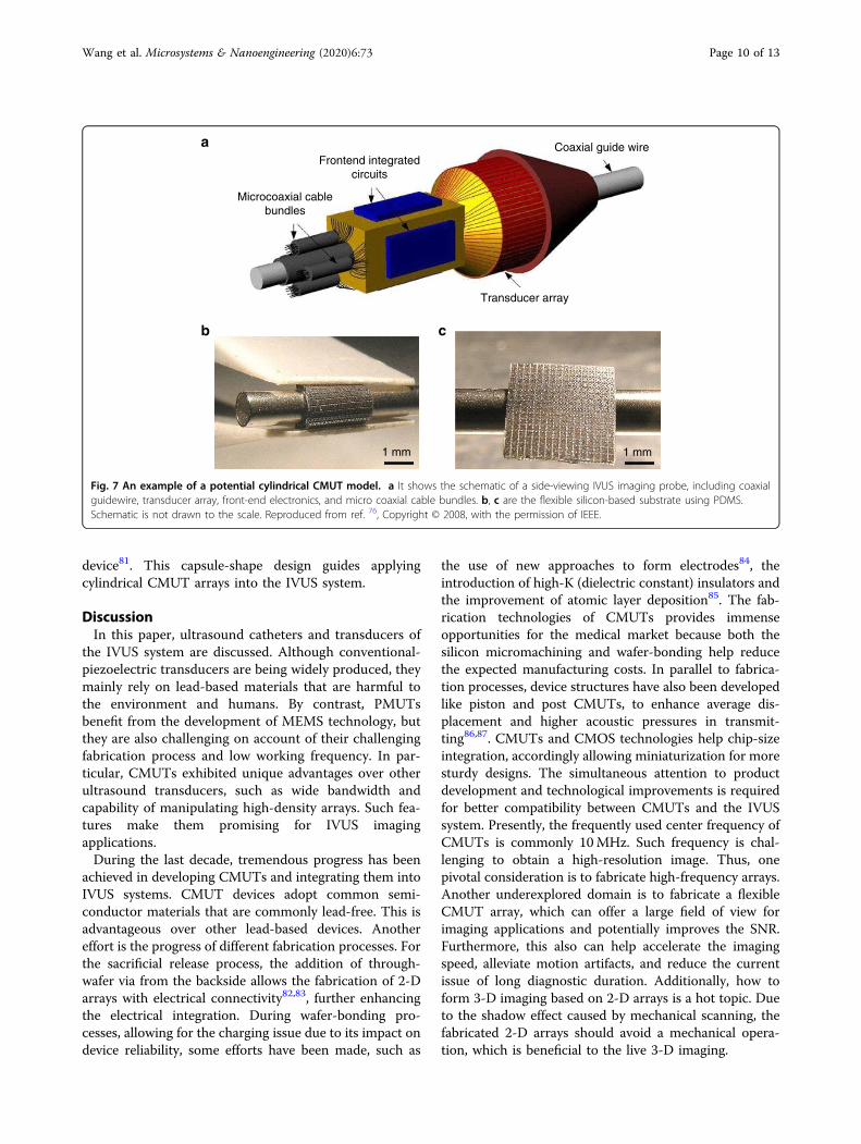
act as a side-viewing model. The fabrication of cylindricalCMUT arrays starts with flexible substrates. These sub-strates can be curved and to cover the cylinder. Next, theycan wrap around the tube tip with ~450 μm radius76.Zhuang et al.76 displayed a CMUT with the flexible sub-strate (Fig. 7c) based on refilled PDMS channels (Fig. 7a, b).In the air, the characterized center frequency ranged from4.3 to 5.0MHz. Potentially, radial CMUT arrays cancombine with FL arrays for enhancing the IVUS system tosimplify the diagnostic and surgical procedures.Researchers also focus on improving the fabrication
process and materials of flexible CMUT arrays. Forinstance, Abgrall et al.77 developed a novel photo-lithography process using lamination technology at lowtemperature and pressure to enhance the bonding tech-nique. A refined roll-lamination approach was lateradopted to produce a transparent flexible CMUT78. In2019, Hah79 updated the previous simulation result anddisplayed a new all-polymer CMUT simulation design forIVUS. The author figured that the current problems offlexible CMUT came from the high-resonant frequencyand draw-in voltage80. At present, cylindrical CMUTarrays have been tested in the capsule ultrasound (CUS)
a b
c10.5
0.5
–5 5 –5 5X (mm) Y (mm)
Z (
mm
)
TX
TX
TX
TX
RX
RX
RX
RX
Digital Control
Fig. 6 An example of a ring CMUT array, experiment instruments, and imaging results. a The schematic of IC for the dual-ring CMUT array. ThisIC includes receive IC, transmit IC, and the digital control circuitry. Schematic is not drawn to the scale. b Experimental device of the CMUT forimaging ex vivo chicken heart phantom. c Imaging results of the chicken heart phantom in XZ and YZ planes with 10 mm dimension size.Reproduced from ref. 74, Copyright © 2014, with the permission of IEEE.
Wang et al. Microsystems & Nanoengineering (2020) 6:73 Page 9 of 13
device81. This capsule-shape design guides applyingcylindrical CMUT arrays into the IVUS system.
DiscussionIn this paper, ultrasound catheters and transducers of
the IVUS system are discussed. Although conventional-piezoelectric transducers are being widely produced, theymainly rely on lead-based materials that are harmful tothe environment and humans. By contrast, PMUTsbenefit from the development of MEMS technology, butthey are also challenging on account of their challengingfabrication process and low working frequency. In par-ticular, CMUTs exhibited unique advantages over otherultrasound transducers, such as wide bandwidth andcapability of manipulating high-density arrays. Such fea-tures make them promising for IVUS imagingapplications.During the last decade, tremendous progress has been
achieved in developing CMUTs and integrating them intoIVUS systems. CMUT devices adopt common semi-conductor materials that are commonly lead-free. This isadvantageous over other lead-based devices. Anothereffort is the progress of different fabrication processes. Forthe sacrificial release process, the addition of through-wafer via from the backside allows the fabrication of 2-Darrays with electrical connectivity82,83, further enhancingthe electrical integration. During wafer-bonding pro-cesses, allowing for the charging issue due to its impact ondevice reliability, some efforts have been made, such as
the use of new approaches to form electrodes84, theintroduction of high-K (dielectric constant) insulators andthe improvement of atomic layer deposition85. The fab-rication technologies of CMUTs provides immenseopportunities for the medical market because both thesilicon micromachining and wafer-bonding help reducethe expected manufacturing costs. In parallel to fabrica-tion processes, device structures have also been developedlike piston and post CMUTs, to enhance average dis-placement and higher acoustic pressures in transmit-ting86,87. CMUTs and CMOS technologies help chip-sizeintegration, accordingly allowing miniaturization for moresturdy designs. The simultaneous attention to productdevelopment and technological improvements is requiredfor better compatibility between CMUTs and the IVUSsystem. Presently, the frequently used center frequency ofCMUTs is commonly 10MHz. Such frequency is chal-lenging to obtain a high-resolution image. Thus, onepivotal consideration is to fabricate high-frequency arrays.Another underexplored domain is to fabricate a flexibleCMUT array, which can offer a large field of view forimaging applications and potentially improves the SNR.Furthermore, this also can help accelerate the imagingspeed, alleviate motion artifacts, and reduce the currentissue of long diagnostic duration. Additionally, how toform 3-D imaging based on 2-D arrays is a hot topic. Dueto the shadow effect caused by mechanical scanning, thefabricated 2-D arrays should avoid a mechanical opera-tion, which is beneficial to the live 3-D imaging.
a
b c
Microcoaxial cablebundles
Frontend integratedcircuits
Coaxial guide wire
Transducer array
1 mm 1 mm
Fig. 7 An example of a potential cylindrical CMUT model. a It shows the schematic of a side-viewing IVUS imaging probe, including coaxialguidewire, transducer array, front-end electronics, and micro coaxial cable bundles. b, c are the flexible silicon-based substrate using PDMS.Schematic is not drawn to the scale. Reproduced from ref. 76, Copyright © 2008, with the permission of IEEE.
Wang et al. Microsystems & Nanoengineering (2020) 6:73 Page 10 of 13
Considering the multifunction of a future portablesystem, CMUTs for IVUS imaging should not be a stand-alone application. The CMUT has successfully achievedthe measurement of sound speed, flow rate, viscosity, andacoustic impedance in the fluid environment, whichprovides a prototype as a portable IVUS assistant tool tomeasure blood density88. Additionally, CMUTs can helpenhance dual-mode for IVUS associated with other fea-tures such as high-intensity focused ultrasound (HIFU) orwith OCT imaging. These combinations would enableresearchers to explore and diagnose coronary diseaseswithin one process directly. The golden era of portableIVUS system with CMUTs to enhance the treatment anddiagnosis of coronary arterial diseases has just begun.
AcknowledgementsThis work was supported by the natural sciences and engineering researchcouncil of Canada (NSERC).
Author ContributionsJiaqi Wang wrote the manuscript and collected data. Zhou Zheng and JasmineChan polished the language. John T.W. Yeow proposed the idea. All authorsreviewed the final manuscript.
Conflict of interestThe authors declare that they have no conflict of interest.
Supplementary information accompanies this paper at https://doi.org/10.1038/s41378-020-0181-z.
Received: 2 February 2020 Revised: 28 April 2020 Accepted: 23 May 2020
References1. Buleu, F., Sirbu, E., Caraba, A. & Dragan, S. Heart involvement in inflammatory
rheumatic diseases: a systematic literature review. Medicina 55, 249 (2019).2. Topol, E. J. & Nissen, S. E. Our preoccupation with coronary luminology: the
dissociation between clinical and angiographic findings in ischemic heartdisease. Circulation 92, 2333–2342 (1995).
3. Nissen, S. E. & Yock, P. Intravascular ultrasound: novel pathophysiologicalinsights and current clinical applications. Circulation 103, 604–616 (2001).
4. Kodach, V. M., Kalkman, J., Faber, D. J. & van Leeuwen, T. G. Quantitativecomparison of the OCT imaging depth at 1300 nm and 1600 nm. Biomed.Opt. Express 1, 176–185 (2010).
5. Fujimoto, J. G. Optical coherence tomography for ultrahigh resolution in vivoimaging. Nat. Biotechnol. 21, 1361–1367 (2003).
6. Nie, L., Guo, Z. & Wang, L. V. Photoacoustic tomography of monkey brainusing virtual point ultrasonic transducers. J. Biomed. Opt. 16, 076005 (2011).
7. Lv, J. et al. In vivo photoacoustic imaging dynamically monitors the structuraland functional changes of ischemic stroke at a very early stage. Theranostics10, 816–828 (2020).
8. Ansari, R., Zhang, E. Z., Desjardins, A. E. & Beard, P. C. All-optical forward-viewing photoacoustic probe for high-resolution 3D endoscopy. Light Sci.Appl. 7, 75 (2018).
9. Li, W. et al. In vivo photoacoustic imaging of brain injury and rehabilitation byhigh-efficient near-infrared dye labeled mesen-chymal stem cells withenhanced brain barrier permeability. Adv. Sci. 5, 1700277 (2018).
10. Huang, W. et al. In vivo quantitative photoacoustic diagnosis of gastric andintestinal dysfunctions with a broad pH-responsive sensor. ACS Nano 13,9561–9570 (2019).
11. Yang, J.-M. et al. Photoacoustic endoscopy. Opt. Lett. 34, 1591–1593 (2009).12. Koganti, S., Kotecha, T. & Rakhit, R. D. Choice of intracoronary imaging: when
to use intravascular ultrasound or optical coherence tomography. Interv.Cardiol. (Lond., Engl.) 11, 11–16 (2016).
13. Fuessl, R. T. et al. In vivo validation of intravascular ultrasound length mea-surements using a motorized transducer pullback system. Am. J. Cardiol. 77,1115–1118 (1996).
14. Mintz, G. S. et al. American College of Cardiology clinical expert consensusdocument on standards for acquisition, measurement and reporting ofintravascular ultrasound studies (IVUS). J. Am. Coll. Cardiol. 37, 1478–1492(2001).
15. Chin, C. Y., Maehara, A., Fall, K., Mintz, G. S. & Ali, Z. A. Imaging comparisons ofcoregistered native and stented coronary segments by high-definition 60-MHz intravascular ultrasound and optical coherence tomography. JACC Car-diovasc. Inter. 9, 1305–1306 (2016).
16. Garcia-Garcia, H. M., Costa, M. A. & Serruys, P. W. Imaging of coronary ather-osclerosis: intravascular ultrasound. Eur. Heart J. 31, 2456–2469c (2010).
17. Shammas, N. W. et al. The role of precise imaging with intravascular ultra-sound in coronary and peripheral interventions. Vasc. Health Risk Manag 15,283–290 (2019).
18. Wang, T. & Lee, C. Zero-bending piezoelectric micromachined ultrasonictransducer (pMUT) with enhanced transmitting performance. J. Microelec-tromech. Syst. 24, 2083–2091 (2015).
19. Cao, Y. et al. A circular array transducer for photoacoustic imaging by usingpiezoelectric single crystal lead magnesium niobate-lead zirconate titanate.Jpn. J. Appl. Phys. 54, 07HD08 (2015).
20. Chen, A. I. H., Wong, L. L. P. & Yeow, J. T. W. inMedical Imaging: Technology andApplications pp. 253–271 (CRC Press, 2013).
21. Tan, J., Sun, W. & Yeow, J. Tracking of square reference signals using internalmodel-based LQG robust controller for positioning of a micro-electro-mechanical systems micromirror. Micro Nano Lett. 13, 704–708 (2018).
22. Bai, Y., Yeow, J. T. W. & Wilson, B. C. Design, fabrication, and characteristics of aMEMS micromirror with sidewall electrodes. J. Microelectromech. Syst. 19,619–631 (2010).
23. Chen, H., Chen, A., Sun, W. J., Sun, Z. D. & Yeow, J. T. W. Closed-loop control ofa 2-D mems micromirror with sidewall electrodes for a laser scanningmicroscope system. Int. J. Optomechatronics 10, 1–13 (2016).
24. Qin, Y., Sun, W. & Yeow, J. T. W. A robust control approach for MEMS capacitivemicromachined ultrasonic transducer. Trans. Inst. Meas. Control 41, 107–116(2019).
25. Jung, J. et al. Review of piezoelectric micromachined ultrasonic transducersand their applications. J. Micromech. Microeng. 27, 113001 (2017).
26. Qiu, Y. et al. Piezoelectric micromachined ultrasound transducer (PMUT)arrays for integrated sensing, actuation and imaging. Sensors 15,8020–8041 (2015).
27. Maity, R. et al. Fringing capacitive effect of silicon carbide based nano-electro-mechanical-system micromachined ultrasonic transducers: ana-lytical modeling and FEM simulation. Trans. Electr. Electron. Mater. 20,473–480 (2019).
28. Wong, L. L. P., Chen, A. I. H., Li, Z., Logan, A. S. & Yeow, J. T. W. A row-columnaddressed micromachined ultrasonic transducer array for surface scanningapplications. Ultrasonics 54, 2072–2080 (2014).
29. Zheng, Z. et al. Development of a novel CMUT-based concentric dual-elementultrasonic transducer: design, fabrication, and characterization. J. Microelec-tromech. Syst. 27, 538–546 (2018).
30. Oralkan, O. et al. Capacitive micromachined ultrasonic transducers: next-generation arrays for acoustic imaging? IEEE Trans. Ultrason. Ferroelectr. Freq.Control 49, 1596–1610 (2002).
31. Ma, T. et al. Multi-frequency intravascular ultrasound (IVUS) imaging. IEEE Trans.Ultrason. Ferroelectr. Freq. Control 62, 97–107 (2015).
32. Kitahara, H., Honda, Y. & Fitzgerald, P. J. Intravascular ultrasound. PanVascularMedicine, 2nd edition. 1379–1418 (2015).
33. Yock, P. G., Linker, D. T., Angelsen, B. A. J. & Tech Two-dimensional intravascularultrasound: technical development and initial clinical experience. J. Am. Soc.Echocardiogr. 2, 296–304 (1989).
34. Kawase, Y. et al. Comparison of nonuniform rotational distortion betweenmechanical IVUS and OCT using a phantom model. Ultrasound Med. Biol. 33,67–73 (2007).
35. Teo, T.-J. Intravascular ultrasound (IVUS) technologies and applications. 2010IEEE International Ultrasonics Symposium 2010, 760–769 (2010).
36. Goh, A. S., Kohn, J. C., Rootman, D. B., Lin, J. L. & Goldberg, R. A. Hyaluronic acidgel distribution pattern in periocular area with high-resolution ultrasoundimaging. Aesthetic Surg. J. 34, 510–515 (2014).
37. Tadigadapa, S. & Mateti, K. Piezoelectric MEMS sensors: state-of-the-art andperspectives. Meas. Sci. Technol. 20, 092001 (2009).
Wang et al. Microsystems & Nanoengineering (2020) 6:73 Page 11 of 13
38. Hejazi, M. M., Jadidian, B. & Safari, A. Fabrication and evaluation of a single-element Bi0.5Na0.5TiO3 -based ultrasonic transducer. IEEE Trans. Ultrason.Fer-roelectr. Freq. Control 59, 1840–1847 (2012).
39. Nascimento, V. M. et al. Influence of backing and matching layers in ultra-sound transducer performance. Proc. of SPIE 5035, 86–96 (2003). https://www.spiedigitallibrary.org/conference-proceedings-of-spie/5035/0000/Influence-of-backing-and-matching-layers-in-ultrasound-transducerperformance/10.1117/12.479924.short.
40. Chen, R. et al. PMN-PT single-crystal high-frequency kerfless phased array. IEEETrans. Ultrason. Ferroelectr. Freq. Control 61, 1033–1041 (2014).
41. Janjic, J. et al. A 2-D ultrasound transducer with front-end ASIC and low cablecount for 3-D forward-looking intravascular imaging: performance and char-acterization. IEEE Trans. Ultrason. Ferroelectr. Freq. Control 65, 1832–1844 (2018).
42. Wildes, D. et al. 4-D ICE: a 2-D array transducer with integrated ASIC in a 10-Frcatheter for real-time 3-D intracardiac echocardiography. IEEE Trans. Ultrason.Ferroelectr. Freq. Control 63, 2159–2173 (2016).
43. Li, X. et al. Micromachined PIN-PMN-PT crystal composite transducer for high-frequency intravascular ultrasound (IVUS) imaging. IEEE Trans. Ultrason. Fer-roelectr. Freq. Control 61, 1171–1178 (2014).
44. Zhu, B. et al. (100)-Textured KNN-based thick film with enhanced piezoelectricproperty for intravascular ultrasound imaging. Appl. Phys. Lett. 106, 173504(2015).
45. Liu, H. et al. Design and fabrication of high frequency BNT film based lineararray transducer. Ceram. Int. 41, S631–S637 (2015).
46. Shelton, S. et al. Aluminum nitride piezoelectric micromachined ultrasoundtransducer arrays. 2012 Solid-State Sensors, Actuators and MicrosystemsWork-shop. 2012, 291–294 (2012).
47. Bathurst, S. P. & Kim, S. G. Printing of uniform PZT thin films for MEMSapplications. CIRP Ann. 62, 227–230 (2013).
48. Li, J., Ren, W., Fan, G. & Wang, C. Design and fabrication of piezoelectricmicromachined ultrasound transducer (pMUT) with partially-etched ZnO film.Sensors 17, 1381 (2017).
49. Mufioz, J. Monolithical AlN PMUT on pre-processed CMOS substrate. 2018 IEEEInternational Frequency Control Symposium (IFCS) 2018, 1–3 (2018).
50. Dallacasa, V., Dallacasa, F., Di Sia, P., Scavetta, E. & Tonelli, D. Nanogeneratorsbased on ZnO or Ti0 2 oxides. J. Nanosci. Nanotechnol. 10, 1043–1050 (2010).
51. Lu, Y., Heidari, A., Shelton, S., Guedes, A. & Horsley, D. A. in 27th IEEE Interna-tional Conference on Micro Electro Mechanical Systems, MEMS 2014 745–748(Institute of Electrical and Electronics Engineers Inc., 2014).
52. Dausch, D. E. et al. In vivo real-time 3-D intracardiac echo using PMUT arrays.IEEE Trans. Ultrason. Ferroelectr. Freq. Control 61, 1754–1764 (2014).
53. Lee, J. et al. 11.1 A 5.37mW/Channel Pitch-Matched Ultrasound ASIC withDynamic-Bit-Shared SAR ADC and 13.2 V Charge-Recycling TX in StandardC-MOS for Intracardiac Echocardiography. 2019 IEEE International Solid-StateCircuits Conference 2019, 190–192 (2019).
54. Degertekin, F. L. Microscale systems based on ultrasonic MEMS-CMOS inte-gration. Transducers 2017, 397–401 (2017).
55. Wong, L. L. P., Chen, A. I., Logan, A. S. & Yeow, J. T. W. An FPGA-basedultrasound imaging system using capacitive micromachined ultrasonictransducers. IEEE Trans. Ultrason. Ferroelectr. Freq. Control 59, 1513–1520 (2012).
56. Salim, M. S., Abd Malek, M. F., Heng, R. B. W., Juni, K. M. & Sabri, N. Capacitivemicromachined ultrasonic transducers: technology and application. J. Med.Ultrasound 20, 8–31 (2012).
57. Logan, A. & Yeow, J. T. W. Fabricating capacitive micromachined ultrasonictransducers with a novel silicon-nitride-Based wafer bonding process. IEEETrans. Ultrason. Ferroelectr. Freq. Control 56, 1074–1084 (2009).
58. Chan, J. et al. Photoacoustic imaging with capacitive micromachined ultra-sound transducers: principles and developments. Sensors 19, 3617 (2019).
59. Yildiz, F., Matsunaga, T. & Haga, Y. Fabrication and packaging of CMUT usinglow temperature co-fired ceramic. Micromachines 9, 553 (2018).
60. Ergun, A. S., Yaralioglu, G. G. & Khuri-Yakub, B. T. Capacitive micromachinedultrasonic transducers: Theory and technology. J. Aerosp. Eng. 16, 76–84 (2003).
61. Na, S. et al. Design and fabrication of a high-power air-coupled capacitivemicromachined ultrasonic transducer array with concentric annular cells. IEEETrans. Electron Devices 64, 4636–4643 (2017).
62. Lemmerhirt, D. F. et al. A 32 x 32 capacitive micromachined ultrasonictransducer array manufactured in standard CMOS. IEEE Trans. Ultrason. Fer-roelectr. Freq. Control 59, 1521–1536 (2012).
63. Bhuyan, A. et al. 3D Volumetric ultrasound imaging with a 32Χ32 CMUT arrayintegrated with front-end ICs using flip-chip bonding technology. 2013 IEEE
International Solid-state Circuits Conference Digest of Technical Papers (ISSCC) 56,396–397 (2013).
64. Wong, L. L. P., Chen, A. I. & Yeow, J. T. W. CMUT Front-End Circuits Designed ina High-Voltage CMOS Process and the Phase Measurement Receiver Circuit.2012 IEEE International Ultrasonics Symposium 2012, 1838–1841 (2012).
65. Tekes, C., Xu, T. & Degertekin, F. L. Investigation of dual mode side and forwardlooking IVUS using a dual ring CMUT-on-CMOS array. 2012 IEEEInternationalUltrasonics Symposium 2012, 1572–1575 (2012).
66. Xu, T. et al. Design, modeling and characterization of a 35MHz 1-D CMUTphased array. 2013 IEEE International Ultrasonics Symposium 2013, 1987–1990(2013).
67. Lim, J., Tekes, C., Degertekin, F. L. & Ghovanloo, M. Towards a reduced-wireinterface for CMUT-based intravascular ultrasound imaging systems. IEEE Trans.Biomed. Circuits Syst. 11, 400–410 (2017).
68. Pekař, M. et al. Quantitative imaging performance of frequency-tunablecapacitive micromachined ultrasonic transducer array designed for intra-cardiac application: phantom study. Ultrasonics 84, 421–429 (2018).
69. Jung, G. et al. Single-chip reduced-wire CMUT-on-CMOS system for intra-cardiac echocardiography. 2018 IEEE International Ultrasonics Symposium 2018,1–4 (2018).
70. Vaithilingam, S. et al. Tomographic photoacoustic imaging using capacitivemicromachined ultrasonic transducer (CMUT) technology. 2006 IEEE Int.Ultrason. Symp . 1, 397–400 (2006).
71. Demirci, U., Ergun, A. S., Oralkan, Ö., Karaman, M. & Khuri-Yakub, B. T. Forward-viewing CMUT arrays for medical imaging. IEEE Trans. Ultrason. Ferroelectr. Freq.Control 51, 887–895 (2004).
72. Guldiken, R. et al. Dual-annular-ring CMUT array for forward-looking IVUSimaging. Proc. IEEE Ultrason. Symp . 1, 698–701 (2006).
73. Yeh, D. T., Oralkan, Ö., Wygant, I. O., O’Donnell, M. & Khuri-Yakub, B. T. 3-DUltrasound imaging using a forward-looking CMUT ring array for intravascular/intracardiac applications. IEEE Trans. Ultrason. Ferroelectr. Freq. Control 53,1202–1210 (2006).
74. Gurun, G. et al. Single-chip CMUT-on-CMOS front-end system for real-timevolumetric IVUS and ICE imaging. IEEE Trans. Ultrason. Ferroelectr. Freq. Control61, 239–250 (2014).
75. Zahorian, J. et al. Monolithic CMUT-on-CMOS integration for intravascularultrasound applications. IEEE Trans. Ultrason. Ferroelectr. Freq. Control 58,2659–2667 (2011).
76. Zhuang, X., Lin, D.-S., Oralkan, Ö. & Khuri-Yakub, B. T. Fabrication of flexibletransducer arrays with through-wafer electrical interconnects based on trenchrefilling with PDMS. J. Microelectromech. Syst. 17, 446–452 (2008).
77. Abgrall, P. et al. Low-stress fabrication of 3D polymer free standing structuresusing lamination of photosensitive films. Microsyst. Technol. 14, 1205–1214(2008).
78. Pang, D.-C. & Chang, C.-M. Development of a novel transparent flexiblecapacitive micromachined ultrasonic transducer. Sensors 17, 1443 (2017).
79. Hah, D. et al. Design of capacitive micromachined ultrasonic transducers(CMUTs) on a flexible substrate for intravascular ultrasonography (IVUS)applications. 2017 Symposium on Design, Test, Integration and Packaging ofMEMS/MOEMS (DTIP) 2017, 1–5 (2017).
80. Hah, D. All-polymer ultrasonic transducer design for an intravascular ultra-sonography application. Turkish J. Electr. Eng. Comput. Sci. 27, 2444–2455(2019).
81. Memon, F. et al. Capsule ultrasound device. 2015 IEEE International UltrasonicsSymposium, IUS 2015, 1–4 (2015).
82. Cheng, C. H. et al. An efficient electrical addressingÿmethod using through-wafer vias for two-dimensional ultrasonic arrays. IEEE Ultrasonics Symposium 2,1179–1182 (2000).
83. Wygant, I. O. et al. Integration of 2D CMUT arrays with front-end electronics forvolumetric ultrasound imaging. IEEE Trans. Ultrason. Ferroelectr. Freq. Control 55,327–342 (2008).
84. Kupnik, M. et al. CMUT fabrication based on a thick buried oxide layer. ProcIEEE Ultrason Symp 2010, 547–550 (2010).
85. Brenner, K. et al. Advances in capacitive micromachined ultrasonic transducers.Micromachines 10, 152 (2019).
86. Yoon, H.-S. et al. Fabrication of CMUT cells with gold center mass for higheroutput pressure. AIP conference proceedings 1359, 183–188 (2011).
87. Nikoozadeh, A. & Khuri-Yakub, P. T. CMUT with substrate-embedded springsfor non-flexural plate movement. Procÿ IEEE Ultrason Symp 2010, 1510–1513(2010).
Wang et al. Microsystems & Nanoengineering (2020) 6:73 Page 12 of 13

88. Saveljic, I., Nikolic, D., Milosevic, Z. & Filipovic, N. in International Conference onMedical and Biological Engineering in Bosnia and Herzegovina, CMBEBIH 2019(Badnjevic, A. et al. eds.) pp. 315–319 (Springer Verlag, 2020).
89. Sung, J. H. & Jeong, J. S. Development of high-frequency (>60 MHz) intra-vascular ultrasound (IVUS) transducer by using asymmetric electrodes forimproved beam profile. Sensors 18, 4414 (2018).
90. Dangi, A. et al. Ring PMUT array based miniaturized photoacoustic endoscopydevice. Proc. SPIE 10878, Photons Plus Ultrasound: Imaging and Sensing,1087811 (2019) https://www.spiedigitallibrary.org/conference-proceedings-of-
spie/10878/2510000/Ring-PMUT-array-based-miniaturized-photoacoustic-endoscopydevice/10.1117/12.2510000.short.
91. Nikoozadeh, A. et al. Forward-looking intracardiac ultrasound imaging using a1-D CMUT array integrated with custom front-end electronics. IEEE Trans.Ultrason. Ferroelectr. Freq. Control 55, 2651–2660 (2008).
92. Tekes, C. et al. Real-time imaging system using a 12-MHz forward-lookingcatheter with single chip CMUT-on-CMOS array. IEEE InternationalUltrasonicsSymposium 2015, 1–4 (2015).
Wang et al. Microsystems & Nanoengineering (2020) 6:73 Page 13 of 13


![PMMA-Based Wafer-Bonded Capacitive Micromachined ... · Transducers for underwater acoustic applications are designed to operate in the 100 kHz–2 MHz frequency range [32]. The transducer,](https://img.pdfslide.net/doc/110x75/600691a7b312da08161bd453/pmma-based-wafer-bonded-capacitive-micromachined-transducers-for-underwater.jpg)