Embed Size (px)
Citation preview

Electronic Components
Capacitor Selection Guide
KEMET makes it possible.

Why Choose KEMET
KEMET Electronics Corporation is a leading global supplier of electronic components. We offer our customers the broadest
selection of capacitor technologies in the industry, along with an expanding range of electromechanical devices,
electromagnetic compatibility solutions and supercapacitors. Our vision is to be the preferred supplier of electronic
component solutions for customers demanding the highest standards of quality, delivery and service.

Aluminum Capacitors Axial Leads ..................................................................................................................................................... 9Radial Crown ................................................................................................................................................ 13Screw Terminal ............................................................................................................................................. 15Snap-In ......................................................................................................................................................... 27Solder Pin/Tag .............................................................................................................................................. 39Single-Ended ................................................................................................................................................ 42Surface Mount .............................................................................................................................................. 52Motor Start .................................................................................................................................................... 55
Ceramic CapacitorsSurface Mount .............................................................................................................................................. 57
Commercial Grade ................................................................................................................................. 57Flex Mitigation ........................................................................................................................................ 61Automotive Grade ................................................................................................................................... 68High Reliability Commercial Off-The-Shelf (COTS) ............................................................................... 78SnPb End Metallization .......................................................................................................................... 80Bulk Capacitance ................................................................................................................................... 87High Temperature ................................................................................................................................... 90High Voltage ........................................................................................................................................... 94Aerospace & Defense ........................................................................................................................... 100RF & Microwave ................................................................................................................................... 105
Leaded ........................................................................................................................................................ 106Commercial Grade ............................................................................................................................... 106High Temperature .................................................................................................................................. 111High Voltage ..........................................................................................................................................118Aerospace & Defense ........................................................................................................................... 122
Disc ..............................................................................................................................................................131Safety ....................................................................................................................................................131Commercial Grade ............................................................................................................................... 139
Film Capacitors Through-Hole .............................................................................................................................................. 143
General Purpose .................................................................................................................................. 143Metallized Polyester ...................................................................................................................... 143Metallized Paper & Polyphenylene Sulfide ..................................................................................... 153
Pulse & AC ........................................................................................................................................... 156Single Metallized Polypropylene .................................................................................................... 156Double Metallized Polypropylene ................................................................................................... 168Film/Foil Polypropylene ...................................................................................................................174
Safety/EMI .............................................................................................................................................177X1 Class ..........................................................................................................................................177X2 Class ........................................................................................................................................ 186Y1 Class ......................................................................................................................................... 196Y2 Class ........................................................................................................................................ 198Multiple X & Y ................................................................................................................................ 202
TABLE OF CONTENTS
Surface Mount ........................................................................................................................................... 205Polyester (PET) .................................................................................................................................... 205Polyethylene Naphthalate (PEN) .......................................................................................................... 208Metallized Polyphenylene Sulfide (PPS) ................................................................................................211Y2 Class ................................................................................................................................................213
Power & Application Optimized ....................................................................................................................214Power Film .............................................................................................................................................214
Axial ................................................................................................................................................214Radial ..............................................................................................................................................218Screw/Faston Terminal .................................................................................................................. 222
Motor Run Applications ........................................................................................................................ 229Screw/Faston Terminal .................................................................................................................. 229
High Voltage Transient Suppression ..................................................................................................... 232Radial ............................................................................................................................................. 232
Low Voltage Transient Suppression ..................................................................................................... 236Radial ............................................................................................................................................. 236
Capacitive AC Power Supply ................................................................................................................ 238Radial ............................................................................................................................................. 238
SupercapacitorsSmall Cell .................................................................................................................................................... 245
Radial ................................................................................................................................................... 245Surface Mount ...................................................................................................................................... 249
Large Cell ................................................................................................................................................... 250Snap-In ................................................................................................................................................. 250Screw Terminal ..................................................................................................................................... 250Bank Module .........................................................................................................................................251
Tantalum CapacitorsSurface Mount ............................................................................................................................................ 253
Standard Tantalum ............................................................................................................................... 253Polymer Tantalum KEMET Organic Capacitor (KO-CAP)..................................................................... 258Polymer Aluminum Organic Capacitor (AO-CAP) ................................................................................. 263High Temperature ................................................................................................................................. 264High Reliability Commercial Off-The-Shelf (COTS) .............................................................................. 265MIL–PRF CWR Style ............................................................................................................................ 275Fused ................................................................................................................................................... 279Automotive Grade ................................................................................................................................. 279Space Grade ........................................................................................................................................ 284
Through-Hole .............................................................................................................................................. 287Hermetically Sealed Axial ..................................................................................................................... 287Radial Dipped ....................................................................................................................................... 303Molded Axial ..........................................................................................................................................310Molded Radial .......................................................................................................................................311
Film Capacitors (cont.)


8
Aluminum Capacitors
ALUMINUM CAPACITORS
Axial Leads Radial Crown Screw Terminal Snap-In Single-Ended Motor StartSurface MountSolder Pin/Tab
EAKLong Life 125°C
10 – 63 VDC
PEG220Very High Ripple Current
150°C25 – 63 VDC
PEH526Automotive
125°C25 – 80 VDC
ESYLow Impedance
105°C6.3 – 100 VDC
ALS42/43High CV Value
105°C 350 – 450 VDC
PEG225Extremely High Ripple Current
125°C & 150°C25 – 63 VDC
PEH532Low ESR & ESL
105°C35 – 450 VDC
ESWLow Impedance
105°C6.3 – 100 VDC
ALS60/61High CV Value
85°C550 VDC
PEG226Extremely High Ripple Current
150°C25 – 63 VDC
PEH534Low ESR & ESL
105°C35 – 450 VDC
ESTLong Life 105°C
6.3 – 63 VDC
PEH169Low ESR
85°C 10 – 450 VDC
PEH536Low ESR & ESL
105°C35 – 450 VDC
PEH169Low ESR & ESL
105°C 10 – 350 VDC
ELHLow Impedance
85°C6.3 – 450 VDC
PEH200High CV Value
85°C 25 – 500 VDC
ELGGeneral Purpose
105°C6.3 – 450 VDC
PEH205High Ripple
125°C 16 – 100 VDC
PEG124Very Long Life
105°C & 125°C10 – 450 VDC
ALC10Long Life
85°C35 – 550 VDC
ALS30/31High CV Value & Long Life
85°C 25 – 500 VDC
PEH126High Ripple Current
150°C25 – 63 VDC
ALP/T 20/21Low ESR
85°C40 – 450 VDC
ESKGeneral Purpose
85°C6.3 – 450 VDC
MS/MD 60°C / 70°C
120 – 300 VAC
A700 Polymer Aluminum
125°C2 – 16 VDC
PEG126High Ripple Current
150°C25 – 63 VDC
ALC10SSlit Foil Audio
85°C50 – 100 VDC
ALP/T 22/23High Ripple
85°C40 – 450 VDC
ESHHigh CV 105°C
6.3 – 500 VDC
ALS32/33High CV Value & Long Life
85°C 350 – 500 VDC
PEH220High Ripple Current
150°C25 – 63 VDC
EDHGerneral Purpose
105°C6.3 – 100 VDC
PEG127High Ripple Current
150°C25 – 63 VDC
ALC40High Ripple Current
105°C25 – 500 VDC
ALN20ST-Network
85°C50 & 100 VDC
ESCLow ESR 105°C
6.3 – 100 VDC
ALS36/37High Ripple Current
85°C 25 – 500 VDC
PEH225High Ripple Current
125°C & 150°C25 – 63 VDC
EDKGeneral Purpose
85°C4 – 450 VDC
PEG130Very Long Life
105°C25 – 63 VDC
PEH506Low ESR & ESL
85°C35 – 450 VDC
ESGHigh Ripple Current
105°C160 – 450 VDC
ALS40/41High CV Value
105°C25 – 500 VDC
PEH226 High Ripple Current
150°C25 – 63 VDC
EEVUltra-Low Impedance
105°C6.3 – 50 VDC
EXVUltra-Low Impedance
105°C6.3 – 50 VDC

9
Aluminum Capacitors
Axial Leads PEG124 Series Very Long Life 105°C & 125°C, 10 – 450 VDCCapacitance Range: 1 to 4,700 µF • Temperature Range: −40°C to +105°C and −40°C to +125°C • Lifetime: 27,500 Hours
• lec
Part Number System
PEG124 E F 410 0 Q T1
Series Voltage (VDC) Size Code Capacitance Code (µF) Version Capacitance Tolerance Packaging
Axial Aluminum Electrolytic
E= 10G = 16H = 25K = 40M = 63
P = 100R = 200U = 350V = 400Y = 450
See Dimension Table The second two digits indicate the two most signifi cant digits of the capacitance value. The
fi rst digit indicates the total number digits.
0 = StandardA-Z = High Performance
Q = -10 +30%M = ±20%T = -10 +50%
See Ordering Options Table
105ºC
Case SizeVoltage
100 200 350 400 45010 x 20 4.7 µF 1 µF
10 x 29 22 µF 10 µF 4.7 µF 2.2 µF 2.2 µF – 3.3 µF
13 x 29 47 µF 15 µF – 22 µF 6.8 µF – 10 µF 4.7 µF 4.7 µF – 6.8 µF
13 x 37 47 µF 10 µF
16 x 29 100 µF 33 µF – 47 µF 22 µF 10 µF
16 x 37 220 µF 22 µF 15 µF
20 x 29 68 µF 33 µF 15 µF – 22 µF
20 x 37 100 µF 47 µF 33 µF 22 µF – 33 µF
20 x 46 470 µF 150 µF 68 µF 47 µF 47 µF 125ºC
Case SizeVoltage
10 16 25 40 6310 x 20 68 µF – 100 µF 47 µF 33 µF 10 µF – 22 µF
10 x 29 150 µF – 220 µF 100 µF 68 µF 33 µF – 47 µF
13 x 20 220 µF – 470 µF 220 µF – 330 µF 150 µF – 220 µF 100 µF
13 x 29 330 µF – 470 µF 220 µF 150 µF 68 µF – 150 µF
13 x 37 680 µF 330 µF 220 µF
16 x 29 1 mF 680 µF – 1 mF 470 µF – 680 µF 220 µF – 470 µF 150 µF – 330 µF
16 x 37 1.5 mF 1 mF – 2.2 mF 680 µF – 1.5 mF 330 µF – 1 mF 220 µF – 680 µF
20 x 37 2.2 mF 1.5 mF – 4.7 mF 1 mF – 3.3 mF 470 µF – 2.2 mF 330 µF – 1 mF
20 x 46 3.3 mF 2.2 mF 1.5 mF – 4 mF 1 mF 470 µF – 1.5 mF
10
Aluminum Capacitors
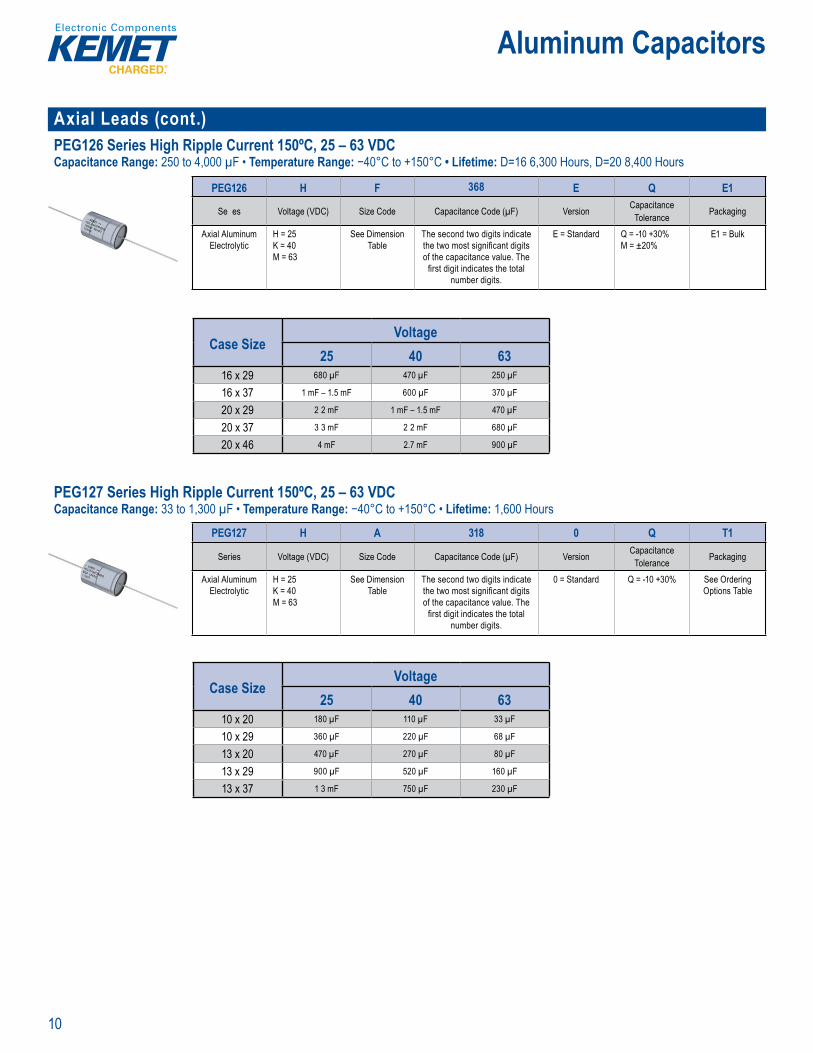
Axial Leads (cont.)PEG126 Series High Ripple Current 150ºC, 25 – 63 VDCCapacitance Range: 250 to 4,000 µF • Temperature Range: −40°C to +150°C • Lifetime: D=16 6,300 Hours, D=20 8,400 Hours
Part Nu be ys e
PEG126 H F 368 E Q E1
Se es Voltage (VDC) Size Code Capacitance Code (µF) Version Capacitance Tolerance Packaging
Axial Aluminum Electrolytic
H = 25K = 40M = 63
See Dimension Table
The second two digits indicate the two most signifi cant digits of the capacitance value. The
fi rst digit indicates the total number digits.
E = Standard Q = -10 +30%M = ±20%
E1 = Bulk
Case SizeVoltage
25 40 6316 x 29 680 µF 470 µF 250 µF
16 x 37 1 mF – 1.5 mF 600 µF 370 µF
20 x 29 2 2 mF 1 mF – 1.5 mF 470 µF
20 x 37 3 3 mF 2 2 mF 680 µF
20 x 46 4 mF 2.7 mF 900 µF PEG127 Series High Ripple Current 150ºC, 25 – 63 VDCCapacitance Range: 33 to 1,300 µF • Temperature Range: −40°C to +150°C • Lifetime: 1,600 Hours
efi ts
1 60 hours 5 ° rat on
in s a 5 C e sizes.
M T 7 g p man o y pac tor. It is de igned fo au o otive applications w th
Part b
PEG127 H A 318 0 Q T1
Series Voltage (VDC) Size Code Capacitance Code (µF) Version Capacitance Tolerance Packaging
Axial Aluminum Electrolytic
H = 25K = 40M = 63
See Dimension Table
The second two digits indicate the two most signifi cant digits of the capacitance value. The
fi rst digit indicates the total number digits.
0 = Standard Q = -10 +30% See Ordering Options Table
Case SizeVoltage
25 40 6310 x 20 180 µF 110 µF 33 µF
10 x 29 360 µF 220 µF 68 µF
13 x 20 470 µF 270 µF 80 µF
13 x 29 900 µF 520 µF 160 µF
13 x 37 1 3 mF 750 µF 230 µF
11
Aluminum Capacitors
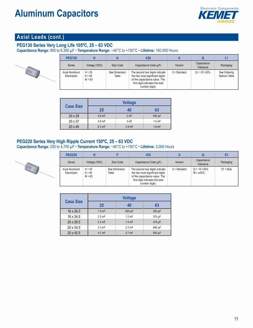
Axial Leads (cont.)PEG130 Series Very Long Life 105ºC, 25 – 63 VDCCapacitance Range: 900 to 6,300 µF • Temperature Range: −40°C to +150°C • Lifetime: 160,000 Hours
P rt N b S t
PEG130 H H 436 0 Q L1
Series Voltage (VDC) Size Code Capacitance Code (µF) Version Capacitance Tolerance Packaging
Axial Aluminum Electrolytic
H = 25K = 40M = 63
See Dimension Table
The second two digits indicate the two most signifi cant digits of the capacitance value. The
fi rst digit indicates the total number digits.
0 = Standard Q = -10 +30% See Ordering Options Table
Case SizeVoltage
25 40 6320 x 29 3.6 mF 2 mF 900 µF
20 x 37 4.8 mF 3 mF 1.4 mF
20 x 46 6 3 mF 3 9 mF 1.8 mF PEG220 Series Very High Ripple Current 150ºC, 25 – 63 VDCCapacitance Range: 250 to 4,700 µF • Temperature Range: −40°C to +150°C • Lifetime: 2,000 Hours
fi
ery ig c e R S
esign, ti ned copper wire lea to the ca e The PEG2 0 win
me
P rt Numbe Sy e
PEG220 H F 415 0 Q E1
Series Voltage (VDC) Size Code Capacitance Code (µF) Version Capacitance Tolerance Packaging
Axial Aluminum Electrolytic
H = 25K = 40M = 63
See Dimension Table
The second two digits indicate the two most signifi cant digits of the capacitance value. The
fi rst digit indicates the total number digits.
0 = Standard Q = -10 +30%M = ±20%
E1 = Bulk
Case SizeVoltage
25 40 6316 x 26.5 1 5 mF 800 µF 250 µF
16 x 34.5 2 2 mF 1.2 mF 370 µF
20 x 26.5 2 2 mF 1 5 mF 470 µF
20 x 34.5 3 3 mF 2 2 mF 680 µF
20 x 42.5 4.7 mF 2.7 mF 900 µF

12
Aluminum Capacitors
Axial Leads (cont.)PEG225 Series Extremely High Ripple Current 125°C & 150°C, 25 – 63 VDC Capacitance Range: 470 to 6,300 µF • Temperature Range: −40°C to +125°C (at UR) and −40°C to +150°C (at reduced voltage) • Lifetime: 2,000 Hours
Part Nu ber System
PEG225 H F 422 0 M
Series Voltage (VDC) Size Code Capacitance Code (µF) Version Capacitance Tolerance
Axial Aluminum Electrolytic
H = 25K = 40M = 63
See Dimension Table The second two digits indicate the two most signifi cant digits of the capacitance value. The fi rst digit indicates the total number digits.
0 = Standard Q = -10 +30%M = ±20%
Case SizeVoltage
25 40 6316 x 26.5 2 2 mF 1.2 mF 470 µF
16 x 34.5 3 mF 1.8 mF 680 µF
20 x 26.5 3.6 mF 2 mF 900 µF
20 x 34.5 4.8 mF 3 mF 1.4 mF
20 x 42.5 6 3 mF 3 9 mF 1.8 mF PEG226 Series Extremely High Ripple Current 150°C, 25 – 63 VDCCapacitance Range: 250 to 4,700 µF • Temperature Range: −40°C to +150°C • Lifetime: 2,000 Hours
0 h rs ° ut
q a le
mechanical obustness the PEG22 s s it le o use in ob e nd a cr instal ations th per t n u to 15 .
MET s PEG226 s a new gen atio of hig perfo mance axial e olytic cap c tors t is desi d f r auto otive p ica o s
rt Nu be Sys e
PEG226 H F 415 0 M
Series Voltage (VDC) Size Code Capacitance Code (µF) Version Capacitance Tolerance
Axial Aluminum Electrolytic
H = 25K = 40M = 63
See Dimension Table The second two digits indicate the two most signifi cant digits of the capacitance value. The fi rst digit indicates the total number digits.
0 = Standard Q = -10 +30%M = ±20%
Case SizeVoltage
25 40 6316 x 26.5 1 5 mF 800 µF 250 µF
16 x 34.5 2 2 mF 1.2 mF 370 µF
20 x 26.5 2 2 mF 1 5 mF 470 µF
20 x 34.5 3 3 mF 2 2 mF 680 µF
20 x 42.5 4.7 mF 2.7 mF 900 µF
13
Aluminum Capacitors
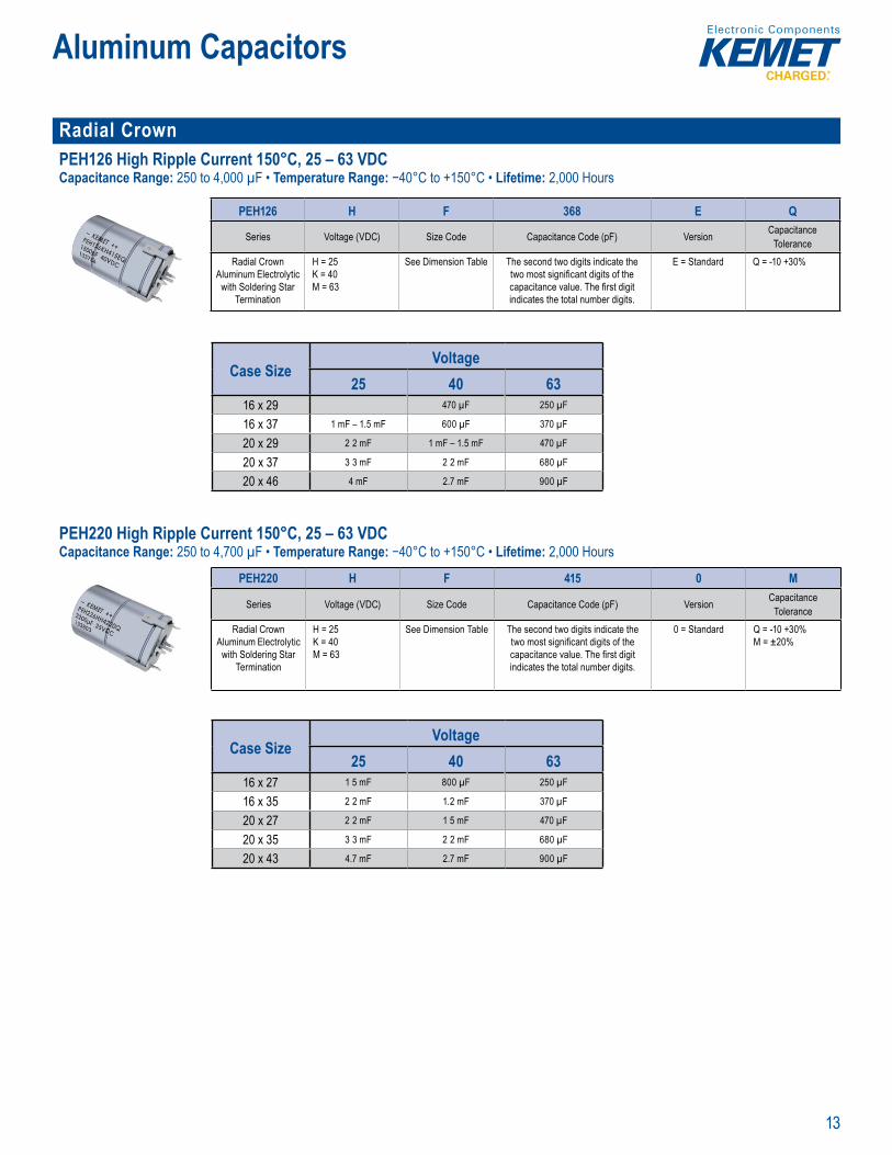
Radial Crown PEH126 High Ripple Current 150°C, 25 – 63 VDCCapacitance Range: 250 to 4,000 µF • Temperature Range: −40°C to +150°C • Lifetime: 2,000 Hours
• a ial ro n whi lo s
art Number System
PEH126 H F 368 E Q
Series Voltage (VDC) Size Code Capacitance Code (pF) Version CapacitanceTolerance
Radial Crown Aluminum Electrolytic
with Soldering Star Termination
H = 25K = 40M = 63
See Dimension Table The second two digits indicate the two most signifi cant digits of the capacitance value. The fi rst digit indicates the total number digits.
E = Standard Q = -10 +30%
Case SizeVoltage
25 40 6316 x 29 470 µF 250 µF
16 x 37 1 mF – 1.5 mF 600 µF 370 µF
20 x 29 2 2 mF 1 mF – 1.5 mF 470 µF
20 x 37 3 3 mF 2 2 mF 680 µF
20 x 46 4 mF 2.7 mF 900 µF PEH220 High Ripple Current 150°C, 25 – 63 VDCCapacitance Range: 250 to 4,700 µF • Temperature Range: −40°C to +150°C • Lifetime: 2,000 Hours
Pa t Sy o
PEH220 H F 415 0 M
Series Voltage (VDC) Size Code Capacitance Code (pF) Version CapacitanceTolerance
Radial Crown Aluminum Electrolytic
with Soldering Star Termination
H = 25K = 40M = 63
See Dimension Table The second two digits indicate the two most signifi cant digits of the capacitance value. The fi rst digit indicates the total number digits.
0 = Standard Q = -10 +30%M = ±20%
Case SizeVoltage
25 40 6316 x 27 1 5 mF 800 µF 250 µF
16 x 35 2 2 mF 1.2 mF 370 µF
20 x 27 2 2 mF 1 5 mF 470 µF
20 x 35 3 3 mF 2 2 mF 680 µF
20 x 43 4.7 mF 2.7 mF 900 µF
14
Aluminum Capacitors
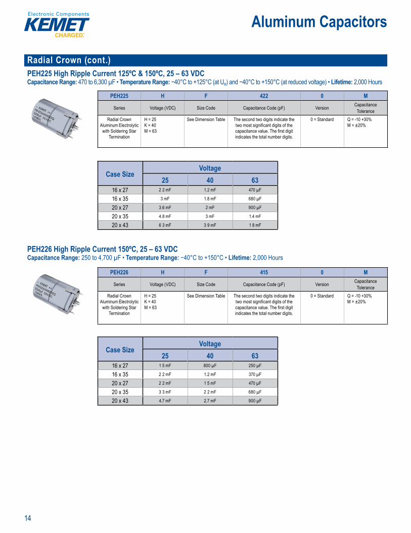
Radial Crown (cont.)PEH225 High Ripple Current 125ºC & 150ºC, 25 – 63 VDC Capacitance Range: 470 to 6,300 µF • Temperature Range: −40°C to +125°C (at UR) and −40°C to +150°C (at reduced voltage) • Lifetime: 2,000 Hours
4 5 0 M
w h
PEH225 H F 422 0 M
Series Voltage (VDC) Size Code Capacitance Code (pF) Version CapacitanceTolerance
Radial Crown Aluminum Electrolytic
with Soldering Star Termination
H = 25K = 40M = 63
See Dimension Table The second two digits indicate the two most signifi cant digits of the capacitance value. The fi rst digit indicates the total number digits.
0 = Standard Q = -10 +30%M = ±20%
Case SizeVoltage
25 40 6316 x 27 2 2 mF 1.2 mF 470 µF
16 x 35 3 mF 1.8 mF 680 µF
20 x 27 3.6 mF 2 mF 900 µF
20 x 35 4.8 mF 3 mF 1.4 mF
20 x 43 6 3 mF 3 9 mF 1 8 mF PEH226 High Ripple Current 150ºC, 25 – 63 VDC Capacitance Range: 250 to 4,700 µF • Temperature Range: −40°C to +150°C • Lifetime: 2,000 Hours
t Num e
PEH220 415
Te mination
e ies ge VD Code p c tan
ad a Crow
ens on n tw
PEH226 H F 415 0 M
Series Voltage (VDC) Size Code Capacitance Code (pF) Version CapacitanceTolerance
Radial Crown Aluminum Electrolytic
with Soldering Star Termination
H = 25K = 40M = 63
See Dimension Table The second two digits indicate the two most signifi cant digits of the capacitance value. The fi rst digit indicates the total number digits.
0 = Standard Q = -10 +30% M = ±20%
Case SizeVoltage
25 40 6316 x 27 1 5 mF 800 µF 250 µF
16 x 35 2 2 mF 1.2 mF 370 µF
20 x 27 2 2 mF 1 5 mF 470 µF
20 x 35 3 3 mF 2 2 mF 680 µF
20 x 43 4.7 mF 2.7 mF 900 µF

15
Aluminum Capacitors
Screw Terminal ALS30/31 Series High CV Value & Long Life 85°C, 25 – 500 VDCCapacitance Range: 100 to 680,000 µF • Temperature Range: −40°C to +85°C • Lifetime: 40,000 Hours
ar Number System
ALS3 0 A 153 DA 025Series Stud Option Termination Capacitance Code (µF) Size Code Voltage (VDC)
Screw TerminalAluminum Electrolytic
0 = Plain Can1 = Threaded mounting stud
See Termination Table
First 2 digits equals fi rst 2 signifi cant fi gures, 3rd digit is the number of additional
zeros.
See Dimension Table
025 = 25040 = 40063 = 63100 = 100200 = 200250 = 250
350 = 350400 = 400415 = 415450 = 450500 = 500
Case SizeVoltage
25 40 63 100 200 250 35036 x 52 15 mF 10 mF 4.7 mF 2.2 mF 470 µF 470 µF 330 µF
36 x 62 22 mF 15 mF 6.8 mF 3.3 mF 680 µF 680 µF
36 x 82 33 mF 22 mF 10 mF 4.7 mF 1 mF 1 mF 470 µF
36 x 105 47 mF 15 mF 6.8 mF 1.5 mF 680 µF
51 x 82 68 mF 33 mF – 0.047 F 15 mF – 0.022 F 10 mF 2.2 mF 1 5 mF – 2.2 mF 1 mF
51 x 105 100 mF 68 mF 33 mF 15 mF 3.3 mF 3.3 mF 1 5 mF – 2.2 mF
63.5 x 10566 x 105 150 mF 100 mF 47 mF 22 mF 4.7 mF – 6.8 mF 4.7 mF 2.2 mF – 3 3 mF
77 x 75 150 mF 100 mF 47 mF 22 mF 4.7 mF 3.3 mF 2.2 mF
77 x 105 220 mF 150 mF 68 mF 33 mF 10 mF 6.8 mF 4.7 mF
77 x 11577 x 146 330 mF 220 mF 100 mF 47 mF 15 mF 10 mF 6.8 mF
77 x 220 470 mF 330 mF 150 mF 68 mF 22 mF 15 mF – 0.022 F 10 mF
90 x 67 220 mF 100 mF 68 mF 22 mF 6.8 mF 6.8 mF 3.3 mF
90 x 75 220 mF 100 mF 47 mF 22 mF 6.8 mF 4.7 mF 3.3 mF
90 x 98 330 mF 150 mF 68 mF 33 mF 10 mF 10 mF 4.7 mF
16
Aluminum Capacitors
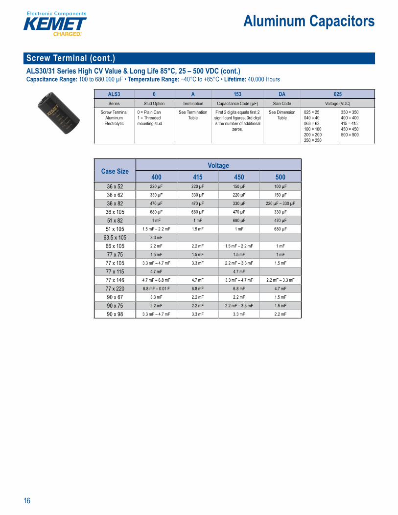
Screw Terminal (cont.) ALS30/31 Series High CV Value & Long Life 85°C, 25 – 500 VDC (cont.)Capacitance Range: 100 to 680,000 µF • Temperature Range: −40°C to +85°C • Lifetime: 40,000 Hours
Part Numbe System
ALS3 0 A 153 DA 025Series Stud Option Termination Capacitance Code (µF) Size Code Voltage (VDC)
Screw TerminalAluminum Electrolytic
0 = Plain Can1 = Threaded mounting stud
See Termination Table
First 2 digits equals fi rst 2 signifi cant fi gures, 3rd digit is the number of additional
zeros.
See Dimension Table
025 = 25040 = 40063 = 63100 = 100200 = 200250 = 250
350 = 350400 = 400415 = 415450 = 450500 = 500
Case SizeVoltage
400 415 450 50036 x 52 220 µF 220 µF 150 µF 100 µF
36 x 62 330 µF 330 µF 220 µF 150 µF
36 x 82 470 µF 470 µF 330 µF 220 µF – 330 µF
36 x 105 680 µF 680 µF 470 µF 330 µF
51 x 82 1 mF 1 mF 680 µF 470 µF
51 x 105 1.5 mF – 2 2 mF 1.5 mF 1 mF 680 µF
63.5 x 10⁵ 3.3 mF
66 x 105 2.2 mF 2.2 mF 1.5 mF – 2 2 mF 1 mF
77 x 75 1.5 mF 1.5 mF 1.5 mF 1 mF
77 x 105 3.3 mF – 4.7 mF 3.3 mF 2.2 mF – 3.3 mF 1.5 mF
77 x 115 4.7 mF 4.7 mF
77 x 146 4.7 mF – 6.8 mF 4.7 mF 3.3 mF – 4.7 mF 2.2 mF – 3.3 mF
77 x 220 6.8 mF – 0.01 F 6.8 mF 6.8 mF 4.7 mF
90 x 67 3.3 mF 2.2 mF 2.2 mF 1.5 mF
90 x 75 2.2 mF 2.2 mF 2.2 mF – 3.3 mF 1.5 mF
90 x 98 3.3 mF – 4.7 mF 3.3 mF 3.3 mF 2.2 mF
17
Aluminum Capacitors
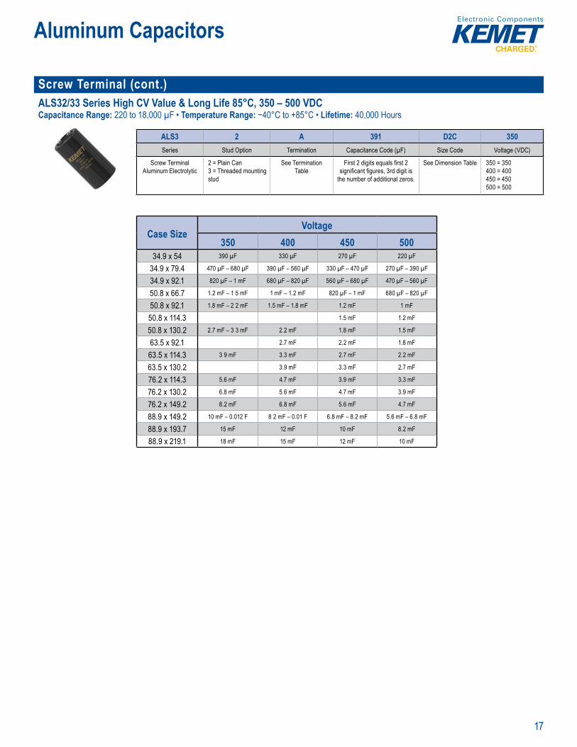
Screw Terminal (cont.)ALS32/33 Series High CV Value & Long Life 85°C, 350 – 500 VDCCapacitance Range: 220 to 18,000 µF • Temperature Range: −40°C to +85°C • Lifetime: 40,000 Hours
Pa t Num r System
ALS3 2 A 391 D2C 350Series Stud Option Termination Capacitance Code (µF) Size Code Voltage (VDC)
Screw Terminal Aluminum Electrolytic
2 = Plain Can3 = Threaded mounting stud
See Termination Table
First 2 digits equals fi rst 2 signifi cant fi gures, 3rd digit is
the number of additional zeros.
See Dimension Table 350 = 350400 = 400450 = 450500 = 500
Case SizeVoltage
350 400 450 50034.9 x 54 390 µF 330 µF 270 µF 220 µF
34.9 x 79.4 470 µF – 680 µF 390 µF – 560 µF 330 µF – 470 µF 270 µF – 390 µF
34.9 x 92.1 820 µF – 1 mF 680 µF – 820 µF 560 µF – 680 µF 470 µF – 560 µF
50.8 x 66.7 1.2 mF – 1 5 mF 1 mF – 1.2 mF 820 µF – 1 mF 680 µF – 820 µF
50.8 x 92.1 1.8 mF – 2 2 mF 1.5 mF – 1.8 mF 1.2 mF 1 mF
50.8 x 114.3 1.5 mF 1.2 mF
50.8 x 130.2 2.7 mF – 3 3 mF 2.2 mF 1.8 mF 1.5 mF
63.5 x 92.1 2.7 mF 2.2 mF 1.8 mF
63.5 x 114.3 3 9 mF 3.3 mF 2.7 mF 2.2 mF
63.5 x 130.2 3.9 mF 3.3 mF 2.7 mF
76.2 x 114.3 5.6 mF 4.7 mF 3.9 mF 3.3 mF
76.2 x 130.2 6.8 mF 5.6 mF 4.7 mF 3.9 mF
76.2 x 149.2 8.2 mF 6.8 mF 5.6 mF 4.7 mF
88.9 x 149.2 10 mF – 0.012 F 8 2 mF – 0.01 F 6.8 mF – 8.2 mF 5.6 mF – 6.8 mF
88.9 x 193.7 15 mF 12 mF 10 mF 8.2 mF
88.9 x 219.1 18 mF 15 mF 12 mF 10 mF
18
Aluminum Capacitors
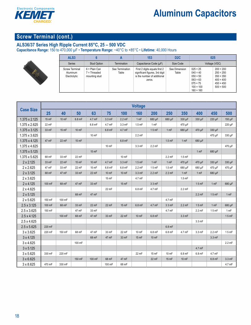
Screw Terminal (cont.)ALS36/37 Series High Ripple Current 85°C, 25 – 500 VDCCapacitance Range: 150 to 470,000 µF • Temperature Range: −40°C to +85°C • Lifetime: 40,000 Hours
art Num r st m
ALS3 6 A 153 D2C 025Series Stud Option Termination Capacitance Code (µF) Size Code Voltage (VDC)
Screw Terminal Aluminum Electrolytic
6 = Plain Can7 = Threaded mounting stud
See Termination Table
First 2 digits equals fi rst 2 signifi cant fi gures, 3rd digit is the number of additional
zeros.
See Dimension Table
025 = 25040 = 40050 = 50063 = 63075 = 75100 = 100160 = 160
200 = 200250 = 250350 = 350400 = 400450 = 450500 = 500
Case SizeVoltage
25 40 50 63 75 100 160 200 250 350 400 450 5001.375 x 2.125 15 mF 10 mF 6.8 mF 4.7 mF 3.3 mF 2.2 mF 1 mF 680 µF 680 µF 330 µF 330 µF 220 µF 150 µF
1.375 x 2.625 22 mF 6.8 mF 4.7 mF 3.3 mF 1.5 mF 1 mF 470 µF 220 µF
1.375 x 3.125 33 mF 15 mF 10 mF 6.8 mF 4.7 mF 1 5 mF 1 mF 680 µF 470 µF 330 µF
1.375 x 3.625 10 mF 2.2 mF 470 µF 330 µF
1.375 x 4.125 47 mF 22 mF 15 mF 6.8 mF 1.5 mF 1 mF 680 µF
1.375 x 4.625 10 mF 3.3 mF 2.2 mF 470 µF
1.375 x 5.125 15 mF 1 mF 680 µF
1.375 x 5.625 68 mF 33 mF 22 mF 10 mF 2.2 mF 1.5 mF
2 x 2.125 33 mF 22 mF 15 mF 10 mF 4.7 mF 3.3 mF 1.5 mF 1 mF 1 mF 470 µF 470 µF 330 µF 330 µF
2 x 2.625 47 mF 33 mF 22 mF 15 mF 6.8 mF 6.8 mF 2.2 mF 1 5 mF 1.5 mF 680 µF 680 µF 470 µF 470 µF
2 x 3.125 68 mF 47 mF 33 mF 22 mF 10 mF 10 mF 3.3 mF 2.2 mF 2 2 mF 1 mF 1 mF 680 µF
2 x 3.625 15 mF 4.7 mF 1.5 mF
2 x 4.125 100 mF 68 mF 47 mF 33 mF 15 mF 3 3 mF 1 5 mF 1 mF 680 µF
2 x 4.625 22 mF 6.8 mF 4.7 mF 2.2 mF
2 x 5.125 68 mF 47 mF 2.2 mF 1 5 mF 1 mF
2 x 5.625 150 mF 100 mF 4.7 mF
2.5 x 3.125 100 mF 68 mF 33 mF 22 mF 22 mF 15 mF 6.8 mF 4.7 mF 3 3 mF 2.2 mF 1 5 mF 1 mF 680 µF
2.5 x 3.625 150 mF 47 mF 33 mF 4.7 mF 2.2 mF 1 5 mF 1 mF
2.5 x 4.125 100 mF 68 mF 47 mF 33 mF 22 mF 10 mF 6.8 mF 3.3 mF 1 5 mF
2.5 x 4.625 3.3 mF
2.5 x 5.625 220 mF 6.8 mF
3 x 3.625 220 mF 150 mF 68 mF 47 mF 33 mF 22 mF 10 mF 6.8 mF 6.8 mF 4.7 mF 3.3 mF 2.2 mF 1 5 mF
3 x 4.125 68 mF 47 mF 33 mF 15 mF 10 mF 3.3 mF
3 x 4.625 100 mF 2.2 mF
3 x 5.125 4.7 mF
3 x 5.625 330 mF 220 mF 22 mF 15 mF 10 mF 6.8 mF 6.8 mF 4.7 mF
3 x 6.625 150 mF 100 mF 68 mF 47 mF 22 mF 15 mF 10 mF 6.8 mF 3.3 mF
3 x 8.625 470 mF 330 mF 100 mF 68 mF 4.7 mF
19
Aluminum Capacitors
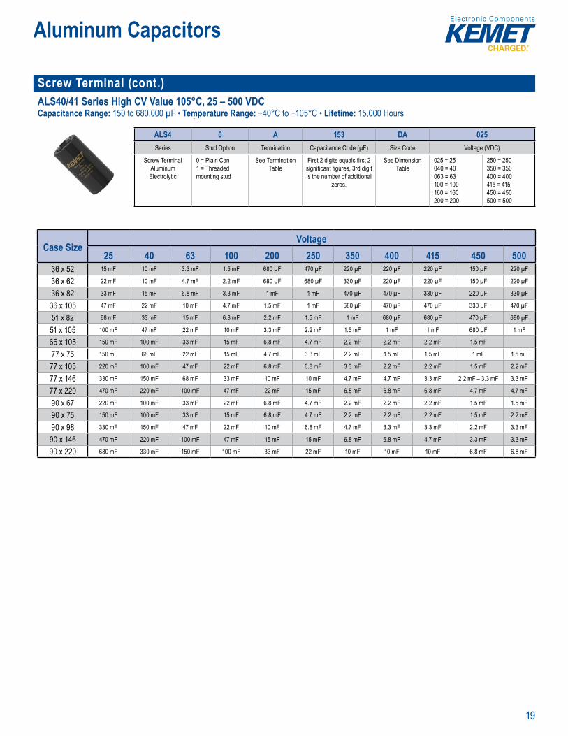
Screw Terminal (cont.)ALS40/41 Series High CV Value 105°C, 25 – 500 VDCCapacitance Range: 150 to 680,000 µF • Temperature Range: −40°C to +105°C • Lifetime: 15,000 Hours
Part Numbe System
ALS4 0 A 153 DA 025Series Stud Option Termination Capacitance Code (µF) Size Code Voltage (VDC)
Screw Terminal Aluminum Electrolytic
0 = Plain Can1 = Threaded mounting stud
See Termination Table
First 2 digits equals fi rst 2 signifi cant fi gures, 3rd digit is the number of additional
zeros.
See Dimension Table
025 = 25040 = 40063 = 63100 = 100160 = 160200 = 200
250 = 250350 = 350400 = 400415 = 415450 = 450500 = 500
Case SizeVoltage
25 40 63 100 200 250 350 400 415 450 50036 x 52 15 mF 10 mF 3.3 mF 1.5 mF 680 µF 470 µF 220 µF 220 µF 220 µF 150 µF 220 µF
36 x 62 22 mF 10 mF 4.7 mF 2.2 mF 680 µF 680 µF 330 µF 220 µF 220 µF 150 µF 220 µF
36 x 82 33 mF 15 mF 6.8 mF 3.3 mF 1 mF 1 mF 470 µF 470 µF 330 µF 220 µF 330 µF
36 x 105 47 mF 22 mF 10 mF 4.7 mF 1.5 mF 1 mF 680 µF 470 µF 470 µF 330 µF 470 µF
51 x 82 68 mF 33 mF 15 mF 6.8 mF 2.2 mF 1.5 mF 1 mF 680 µF 680 µF 470 µF 680 µF
51 x 105 100 mF 47 mF 22 mF 10 mF 3.3 mF 2.2 mF 1.5 mF 1 mF 1 mF 680 µF 1 mF
66 x 105 150 mF 100 mF 33 mF 15 mF 6.8 mF 4.7 mF 2.2 mF 2.2 mF 2.2 mF 1.5 mF
77 x 75 150 mF 68 mF 22 mF 15 mF 4.7 mF 3.3 mF 2.2 mF 1 5 mF 1.5 mF 1 mF 1.5 mF
77 x 105 220 mF 100 mF 47 mF 22 mF 6.8 mF 6.8 mF 3 3 mF 2.2 mF 2.2 mF 1.5 mF 2.2 mF
77 x 146 330 mF 150 mF 68 mF 33 mF 10 mF 10 mF 4.7 mF 4.7 mF 3.3 mF 2 2 mF – 3.3 mF 3.3 mF
77 x 220 470 mF 220 mF 100 mF 47 mF 22 mF 15 mF 6.8 mF 6.8 mF 6.8 mF 4.7 mF 4.7 mF
90 x 67 220 mF 100 mF 33 mF 22 mF 6.8 mF 4.7 mF 2.2 mF 2.2 mF 2.2 mF 1.5 mF 1.5 mF
90 x 75 150 mF 100 mF 33 mF 15 mF 6.8 mF 4.7 mF 2.2 mF 2.2 mF 2.2 mF 1.5 mF 2.2 mF
90 x 98 330 mF 150 mF 47 mF 22 mF 10 mF 6.8 mF 4.7 mF 3.3 mF 3.3 mF 2.2 mF 3.3 mF
90 x 146 470 mF 220 mF 100 mF 47 mF 15 mF 15 mF 6.8 mF 6.8 mF 4.7 mF 3.3 mF 3.3 mF
90 x 220 680 mF 330 mF 150 mF 100 mF 33 mF 22 mF 10 mF 10 mF 10 mF 6.8 mF 6.8 mF
20
Aluminum Capacitors
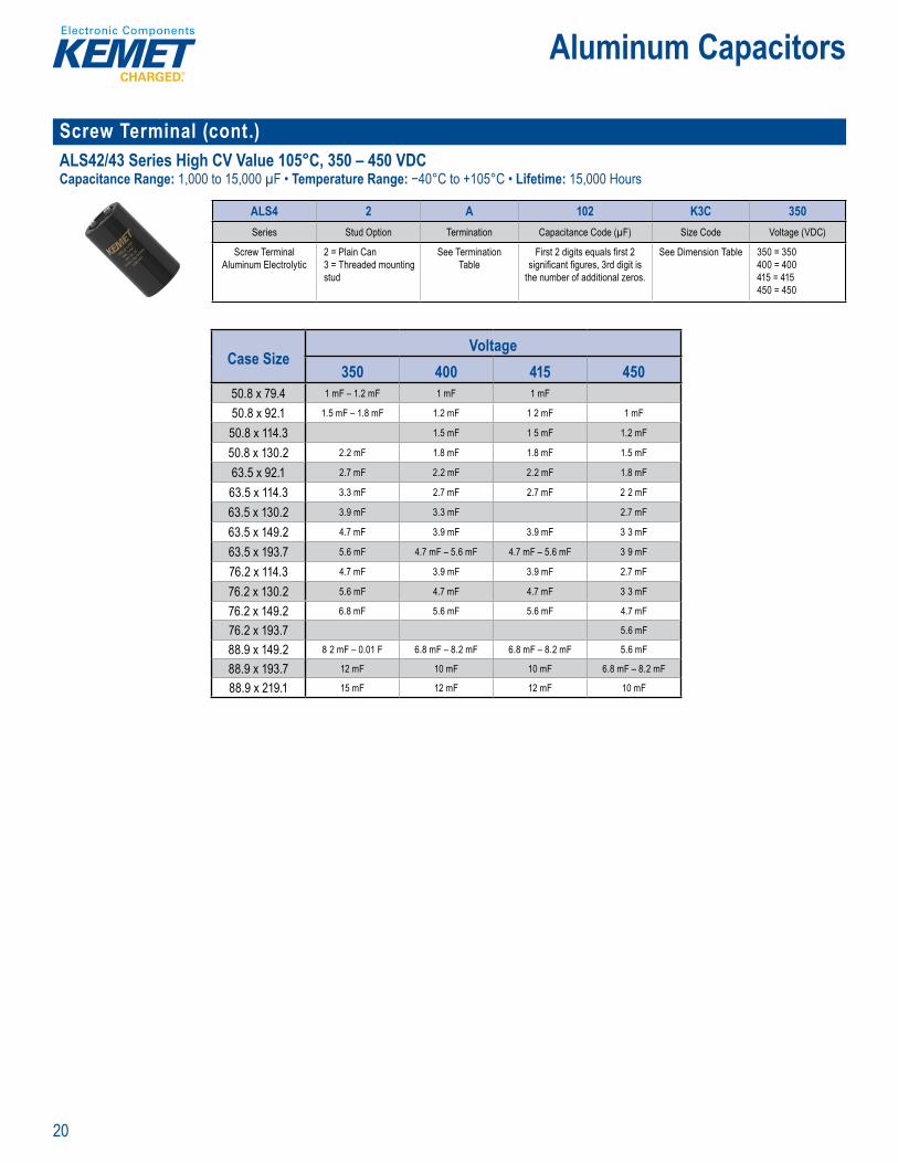
Screw Terminal (cont.)ALS42/43 Series High CV Value 105°C, 350 – 450 VDCCapacitance Range: 1,000 to 15,000 µF • Temperature Range: −40°C to +105°C • Lifetime: 15,000 Hours
P rt Numb System
ALS4 2 A 102 K3C 350Series Stud Option Termination Capacitance Code (µF) Size Code Voltage (VDC)
Screw Terminal Aluminum Electrolytic
2 = Plain Can3 = Threaded mounting stud
See Termination Table
First 2 digits equals fi rst 2 signifi cant fi gures, 3rd digit is
the number of additional zeros.
See Dimension Table 350 = 350400 = 400415 = 415450 = 450
Case SizeVoltage
350 400 415 45050.8 x 79.4 1 mF – 1.2 mF 1 mF 1 mF
50.8 x 92.1 1.5 mF – 1.8 mF 1.2 mF 1 2 mF 1 mF
50.8 x 114.3 1.5 mF 1 5 mF 1.2 mF
50.8 x 130.2 2.2 mF 1.8 mF 1.8 mF 1.5 mF
63.5 x 92.1 2.7 mF 2.2 mF 2.2 mF 1.8 mF
63.5 x 114.3 3.3 mF 2.7 mF 2.7 mF 2 2 mF
63.5 x 130.2 3.9 mF 3.3 mF 2.7 mF
63.5 x 149.2 4.7 mF 3.9 mF 3.9 mF 3 3 mF
63.5 x 193.7 5.6 mF 4.7 mF – 5.6 mF 4.7 mF – 5.6 mF 3 9 mF
76.2 x 114.3 4.7 mF 3.9 mF 3.9 mF 2.7 mF
76.2 x 130.2 5.6 mF 4.7 mF 4.7 mF 3 3 mF
76.2 x 149.2 6.8 mF 5.6 mF 5.6 mF 4.7 mF
76.2 x 193.7 5.6 mF
88.9 x 149.2 8 2 mF – 0.01 F 6.8 mF – 8.2 mF 6.8 mF – 8.2 mF 5.6 mF
88.9 x 193.7 12 mF 10 mF 10 mF 6.8 mF – 8.2 mF
88.9 x 219.1 15 mF 12 mF 12 mF 10 mF
21
Aluminum Capacitors
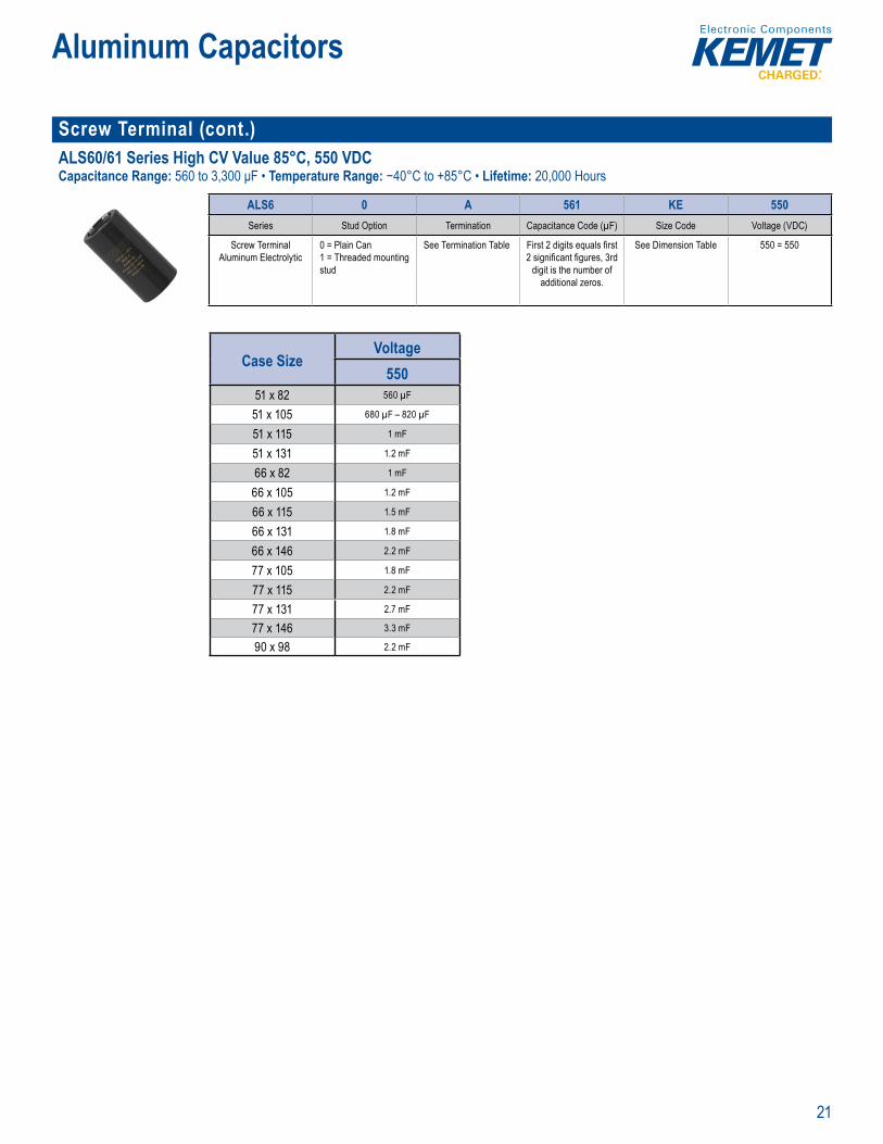
Screw Terminal (cont.)ALS60/61 Series High CV Value 85°C, 550 VDCCapacitance Range: 560 to 3,300 μF • Temperature Range: −40°C to +85°C • Lifetime: 20,000 Hours
rt Nu ber Sys em
ALS6 0 A 561 KE 550Series Stud Option Termination Capacitance Code (µF) Size Code Voltage (VDC)
Screw Terminal Aluminum Electrolytic
0 = Plain Can1 = Threaded mounting stud
See Termination Table First 2 digits equals fi rst 2 signifi cant fi gures, 3rd
digit is the number of additional zeros.
See Dimension Table 550 = 550
Case SizeVoltage
55051 x 82 560 µF
51 x 105 680 µF – 820 µF
51 x 115 1 mF
51 x 131 1.2 mF
66 x 82 1 mF
66 x 105 1.2 mF
66 x 115 1.5 mF
66 x 131 1.8 mF
66 x 146 2.2 mF
77 x 105 1.8 mF
77 x 115 2.2 mF
77 x 131 2.7 mF
77 x 146 3.3 mF
90 x 98 2.2 mF

22
Aluminum Capacitors
Screw Terminal (cont.)PEH169 Series Low ESR 85°C, 10 – 450 VDCCapacitance Range: 68 to 470,000 µF • Temperature Range: −40°C to +85°C • Lifetime: 78,000 Hours
Pa t Num r System
PEH169 E A 510 V M U2
Series Rated Voltage (VDC) Size Code Capacitance Code (µF) Version Capacitance Tolerance Stud Option
Screw Terminal Aluminum Electrolytic
E = 10G = 16H = 25K = 40M = 63P = 100Q = 160
R = 200S = 250U = 350V = 400O = 420Y = 450
See Dimension Table The second 2 digits indicate the 2 most signifi cant digits of the capacitance value.
The fi rst digit indicates the total number digits.
0 = Standard Q = -10 +30%M = ±20%
U2 = Plain CanB2 = Threaded mounting stud
Case SizeVoltage
10 16 25 40 63 10036.6 x 51.5 10 mF – 0.015 F 10 mF – 0.015 F 6 mF – 0.01 F 4.7 mF 2.2 mF – 3.3 mF 1 mF – 1.5 mF
36.6 x 59.5 22 mF 6.8 mF
36.6 x 73.5 33 mF 22 mF 15 mF 10 mF 4.7 mF 2 2 mF
36.6 x 94.5 47 mF 33 mF 22 mF 15 mF 6.8 mF 3 3 mF
51.6 x 74.5 68 mF 47 mF 33 mF 22 mF 10 mF 4.7 mF
51.6 x 95.5 100 mF 68 mF 47 mF 33 mF 15 mF 6.8 mF
51.6 x 103.5 150 mF 22 mF 10 mF
66.6 x 10⁶ 220 mF 100 mF 68 mF 47 mF 15 mF
76.6 x 10⁶ 150 mF 100 mF 68 mF 33 mF
76.6 x 118 330 mF 220 mF 150 mF 100 mF 47 mF 22 mF
76.6 x 146 470 mF 330 mF 220 mF 150 mF 68 mF – 0.082 F 33 mF
Case SizeVoltage
160 200 250 350 400 420 45036.6 x 51.5 470 µF – 680 µF 470 µF 220 µF – 330 µF 150 µF – 220 µF 68 µF – 150 µF 68 µF 68 µF
36.6 x 59.5 680 µF 470 µF 150 µF – 220 µF 100 µF 100 µF
36.6 x 73.5 1 mF 680 µF 330 µF 220 µF – 330 µF 150 µF 150 µF
36.6 x 94.5 1.5 mF 1 mF 470 µF 220 µF 220 µF
51.6 x 74.5 2.2 mF 1.5 mF 1 mF – 1.5 mF 680 µF 330 µF – 470 µF 330 µF 330 µF
51.6 x 95.5 3.3 mF 2.2 mF 1 mF 470 µF 470 µF
51.6 x 103.5 3 3 mF 2.2 mF 1 5 mF 680 µF – 1 mF 680 µF 680 µF
66.6 x 10⁶ 4.7 mF 4.7 mF 3.3 mF 2 2 mF 1 mF – 1.5 mF 1 mF 1 mF
76.6 x 98 2.2 mF
76.6 x 10⁶ 6.8 mF 6.8 mF 4.7 mF 3 3 mF 1.5 mF – 2.2 mF 1 5 mF 1.5 mF
76.6 x 118 10 mF
76.6 x 146 15 mF 10 mF 6.8 mF – 8.8 mF 4.7 mF 2.2 mF – 3 3 mF 2.2 mF 2.2 mF
76.6 x 221 10 mF 6.8 mF 4.7 mF 3.3 mF 3.3 mF

23
Aluminum Capacitors
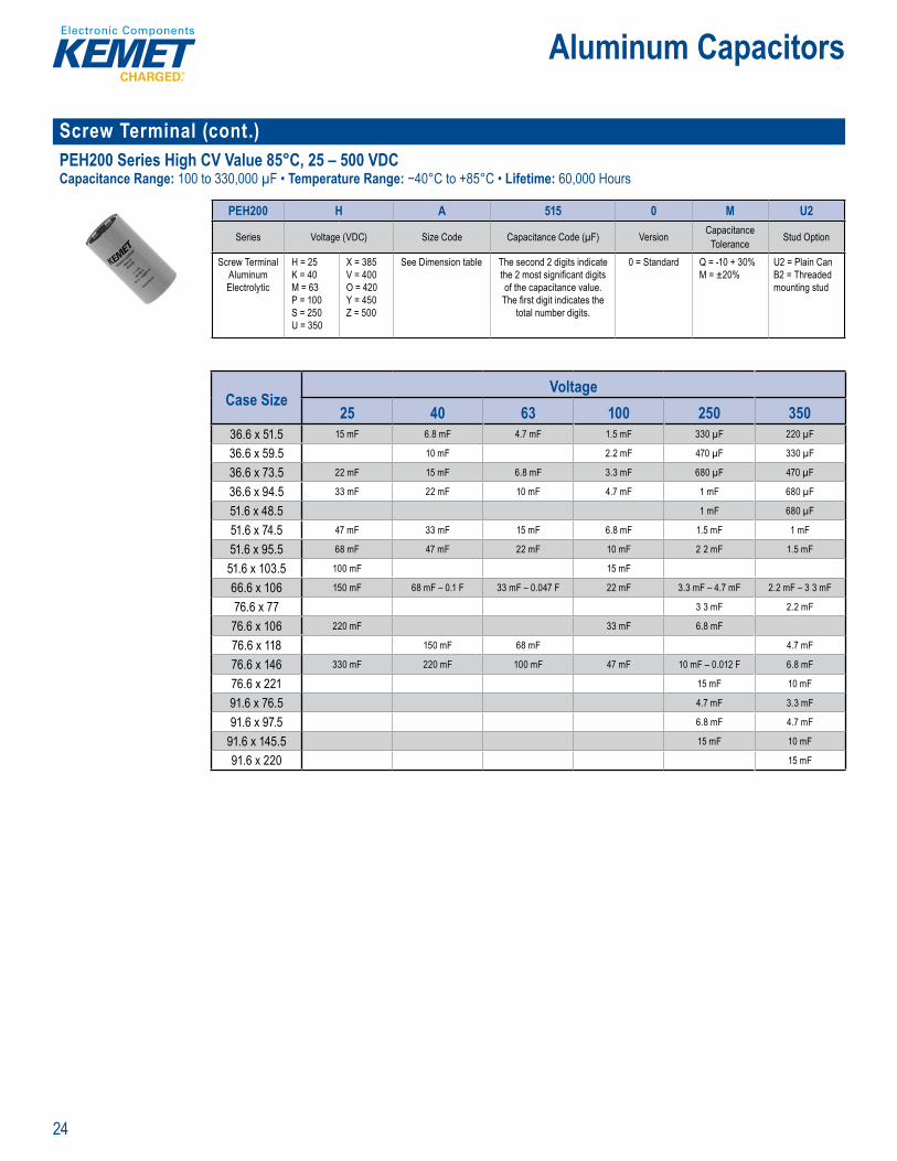
Screw Terminal (cont.)PEH169 Series Low ESR & ESL 105°C, 10 – 350 VDCCapacitance Range: 100 to 330,000 µF • Temperature Range: −40°C to +105°C • Lifetime: 25,000 Hours
ar Number System
PEH169 E A 468 0 Q U2
Series Rated Voltage (VDC) Size Code Capacitance Code (µF) Version Capacitance Tolerance Stud Option
Screw TerminalAluminum Electrolytic
E = 10G = 16H = 25K = 40M = 63
P = 100Q = 160R = 200S = 250U = 350
See Dimension Table The second 2 digits indicate the 2 most signifi cant digits of the capacitance value.
The fi rst digit indicates the total number digits.
0 = Standard Q = -10 +30% U2 = Plain CanB2 = Threaded mounting stud
Case SizeVoltage
10 16 25 40 63 10036.6 x 51.5 6.8 mF – 0.01 F 6.8 mF – 0.01 F 4.7 mF – 6.8 mF 3.3 mF 1.5 mF – 2 2 mF 680 µF – 1 mF
36.6 x 59.5 15 mF 4.7 mF
36.6 x 73.5 22 mF 15 mF 10 mF 6.8 mF 3.3 mF 1.5 mF
36.6 x 94.5 33 mF 22 mF 15 mF 10 mF 4.7 mF 2 2 mF
51.6 x 74.5 47 mF 33 mF 22 mF 15 mF 6.8 mF 3 3 mF
51.6 x 95.5 68 mF 47 mF 33 mF 22 mF 10 mF 4.7 mF
51.6 x 103.5 100 mF
66.6 x 10⁶ 150 mF 68 mF 47 mF 33 mF 15 mF 6.8 mF – 0.01 F
76.6 x 10⁶ 220 mF 100 mF 68 mF 47 mF 22 mF
76.6 x 118 150 mF 100 mF 68 mF 33 mF 15 mF
76.6 x 146 330 mF 220 mF 150 mF 100 mF 47 mF 22 mF
Case SizeVoltage
160 200 250 35036.6 x 51.5 330 µF – 470 µF 330 µF 150 µF – 220 µF 100 µF – 150 µF
36.6 x 59.5 470 µF 330 µF
36.6 x 73.5 680 µF 470 µF 220 µF
36.6 x 94.5 1 mF 680 µF 330 µF
51.6 x 74.5 1.5 mF 1 mF 680 µF – 1 mF 470 µF
51.6 x 95.5 2.2 mF 1.5 mF 680 µF
51.6 x 103.5 2.2 mF 1.5 mF 1 mF
66.6 x 10⁶ 3.3 mF 3.3 mF 2.2 mF 1.5 mF
76.6 x 10⁶ 4.7 mF 4.7 mF 3.3 mF 2.2 mF
76.6 x 118 6.8 mF
76.6 x 146 10 mF 6.8 mF 4.7 mF 3.3 mF
76.6 x 221 6.8 mF 4.7 mF
91.6 x 145.5 6.8 mF 4.7 mF
24
Aluminum Capacitors
Screw Terminal (cont.)PEH200 Series High CV Value 85°C, 25 – 500 VDCCapacitance Range: 100 to 330,000 µF • Temperature Range: −40°C to +85°C • Lifetime: 60,000 Hours
ar Number System
PEH200 H A 515 0 M U2
Series Voltage (VDC) Size Code Capacitance Code (µF) Version Capacitance Tolerance Stud Option
Screw Terminal Aluminum Electrolytic
H = 25K = 40M = 63P = 100S = 250U = 350
X = 385V = 400O = 420Y = 450Z = 500
See Dimension table The second 2 digits indicate the 2 most signifi cant digits of the capacitance value.
The fi rst digit indicates the total number digits.
0 = Standard Q = -10 + 30%M = ±20%
U2 = Plain CanB2 = Threaded mounting stud
Case SizeVoltage
25 40 63 100 250 35036.6 x 51.5 15 mF 6.8 mF 4.7 mF 1.5 mF 330 µF 220 µF
36.6 x 59.5 10 mF 2.2 mF 470 µF 330 µF
36.6 x 73.5 22 mF 15 mF 6.8 mF 3.3 mF 680 µF 470 µF
36.6 x 94.5 33 mF 22 mF 10 mF 4.7 mF 1 mF 680 µF
51.6 x 48.5 1 mF 680 µF
51.6 x 74.5 47 mF 33 mF 15 mF 6.8 mF 1.5 mF 1 mF
51.6 x 95.5 68 mF 47 mF 22 mF 10 mF 2 2 mF 1.5 mF
51.6 x 103.5 100 mF 15 mF
66.6 x 10⁶ 150 mF 68 mF – 0.1 F 33 mF – 0.047 F 22 mF 3.3 mF – 4.7 mF 2.2 mF – 3 3 mF
76.6 x 77 3 3 mF 2.2 mF
76.6 x 10⁶ 220 mF 33 mF 6.8 mF
76.6 x 118 150 mF 68 mF 4.7 mF
76.6 x 146 330 mF 220 mF 100 mF 47 mF 10 mF – 0.012 F 6.8 mF
76.6 x 221 15 mF 10 mF
91.6 x 76.5 4.7 mF 3.3 mF
91.6 x 97.5 6.8 mF 4.7 mF
91.6 x 145.5 15 mF 10 mF
91.6 x 220 15 mF
25
Aluminum Capacitors
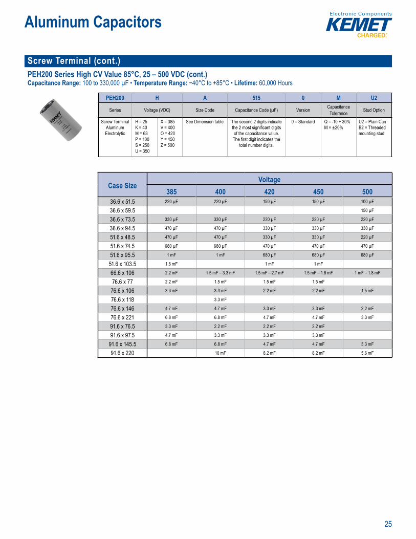
Screw Terminal (cont.)PEH200 Series High CV Value 85°C, 25 – 500 VDC (cont.)Capacitance Range: 100 to 330,000 µF • Temperature Range: −40°C to +85°C • Lifetime: 60,000 Hours
ar Number System
PEH200 H A 515 0 M U2
Series Voltage (VDC) Size Code Capacitance Code (µF) Version Capacitance Tolerance Stud Option
Screw Terminal Aluminum Electrolytic
H = 25K = 40M = 63P = 100S = 250U = 350
X = 385V = 400O = 420Y = 450Z = 500
See Dimension table The second 2 digits indicate the 2 most signifi cant digits of the capacitance value.
The fi rst digit indicates the total number digits.
0 = Standard Q = -10 + 30%M = ±20%
U2 = Plain CanB2 = Threaded mounting stud
Case SizeVoltage
385 400 420 450 50036.6 x 51.5 220 µF 220 µF 150 µF 150 µF 100 µF
36.6 x 59.5 150 µF
36.6 x 73.5 330 µF 330 µF 220 µF 220 µF 220 µF
36.6 x 94.5 470 µF 470 µF 330 µF 330 µF 330 µF
51.6 x 48.5 470 µF 470 µF 330 µF 330 µF 220 µF
51.6 x 74.5 680 µF 680 µF 470 µF 470 µF 470 µF
51.6 x 95.5 1 mF 1 mF 680 µF 680 µF 680 µF
51.6 x 103.5 1.5 mF 1 mF 1 mF
66.6 x 10⁶ 2.2 mF 1 5 mF – 3.3 mF 1.5 mF – 2.7 mF 1.5 mF – 1.8 mF 1 mF – 1.8 mF
76.6 x 77 2.2 mF 1.5 mF 1.5 mF 1.5 mF
76.6 x 10⁶ 3.3 mF 3.3 mF 2.2 mF 2.2 mF 1.5 mF
76.6 x 118 3.3 mF
76.6 x 146 4.7 mF 4.7 mF 3.3 mF 3.3 mF 2.2 mF
76.6 x 221 6.8 mF 6.8 mF 4.7 mF 4.7 mF 3.3 mF
91.6 x 76.5 3.3 mF 2.2 mF 2.2 mF 2.2 mF
91.6 x 97.5 4.7 mF 3.3 mF 3.3 mF 3.3 mF
91.6 x 145.5 6.8 mF 6.8 mF 4.7 mF 4.7 mF 3.3 mF
91.6 x 220 10 mF 8.2 mF 8.2 mF 5.6 mF
26
Aluminum Capacitors
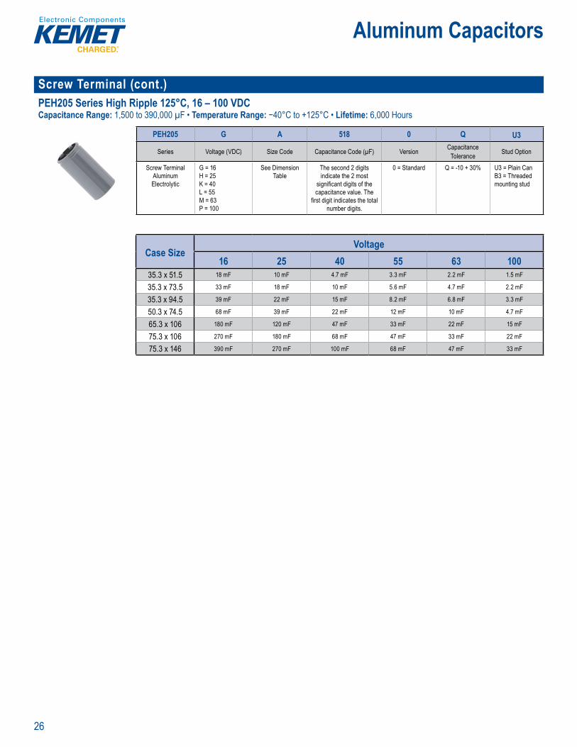
Screw Terminal (cont.)PEH205 Series High Ripple 125°C, 16 – 100 VDCCapacitance Range: 1,500 to 390,000 µF • Temperature Range: −40°C to +125°C • Lifetime: 6,000 Hours
P rt Numbe System
PEH205 G A 518 0 Q U3
Series Voltage (VDC) Size Code Capacitance Code (µF) Version Capacitance Tolerance Stud Option
Screw TerminalAluminum Electrolytic
G = 16H = 25K = 40L = 55M = 63P = 100
See Dimension Table
The second 2 digits indicate the 2 most
signifi cant digits of the capacitance value. The
fi rst digit indicates the total number digits.
0 = Standard Q = -10 + 30% U3 = Plain CanB3 = Threaded mounting stud
Case SizeVoltage
16 25 40 55 63 10035.3 x 51.5 18 mF 10 mF 4.7 mF 3.3 mF 2.2 mF 1.5 mF
35.3 x 73.5 33 mF 18 mF 10 mF 5.6 mF 4.7 mF 2.2 mF
35.3 x 94.5 39 mF 22 mF 15 mF 8.2 mF 6.8 mF 3.3 mF
50.3 x 74.5 68 mF 39 mF 22 mF 12 mF 10 mF 4.7 mF
65.3 x 10⁶ 180 mF 120 mF 47 mF 33 mF 22 mF 15 mF
75.3 x 10⁶ 270 mF 180 mF 68 mF 47 mF 33 mF 22 mF
75.3 x 146 390 mF 270 mF 100 mF 68 mF 47 mF 33 mF

27
Aluminum Capacitors
Snap-In ALC10 Series Long Life 85°C, 35 – 550 VDCCapacitance Range: 56 to 82,000 µF • Temperature Range: −40°C to +85°C • Lifetime: 29,000 Hours
Part Number System
ALC10 A 392 BB 040Series Termination Capacitance Code (µF) Size Code Rated Voltage (VDC)
Snap-In type Aluminum Electrolytic
See Termination Table First two digits represent signifi cant fi gures. Third digit specifi es number of
zeros.
See Dimension Table 035 = 35040 = 40063 = 63100 = 100200 = 200250 = 250
350 = 350400 = 400450 = 450500 = 500550 = 550
Case SizeVoltage
35 40 63 100 200 250 350 400 450 500 55025 x 30 3.9 mF 2.2 mF 1 mF 330 µF 220 µF 120 µF 100 µF 68 µF 56 µF 56 µF
25 x 35 4.7 mF 2.7 mF 1.2 mF 390 µF 270 µF – 330 µF 150 µF 120 µF 100 µF 68 µF 68 µF
25 x 40 5.6 mF 3.3 mF 1.5 mF 470 µF 330 µF 180 µF 150 µF 120 µF – 150 µF 82 µF 82 µF
30 x 30 5.6 mF 3.3 mF 1.5 mF 470 µF 330 µF 180 µF 150 µF 120 µF – 150 µF 82 µF – 100 µF 82 µF
30 x 35 6.8 mF 4.7 mF 1.8 mF 560 µF 470 µF 270 µF 180 µF – 220 µF 150 µF 100 µF – 120 µF 120 µF
30 x 40 8.2 mF 5.6 mF 2.2 mF 680 µF 560 µF 330 µF 220 µF 180 µF 150 µF 150 µF
30 x 50 12 mF 6.8 mF 3.3 mF 1 mF 680 µF 390 µF 330 µF 220 µF – 330 µF 180 µF 180 µF
35 x 35 10 mF 6.8 mF 2.7 mF 820 µF 680 µF 390 µF 270 µF – 330 µF 220 µF – 270 µF 180 µF 180 µF
35 x 40 12 mF 8.2 mF 3.3 mF 1 mF 820 µF 470 µF 330 µF 270 µF 220 µF 220 µF
35 x 50 18 mF 10 mF 4.7 mF 1.2 mF – 1.5 mF 1 mF 560 µF 390 µF – 560 µF 330 µF – 470 µF 270 µF 270 µF
35 x 60 1.2 mF 820 µF 560 µF – 680 µF 470 µF 390 µF 330 µF
35 x 80 1.8 mF 1 mF 820 µF – 1 mF 680 µF 560 µF 470 µF
40 x 30 15 mF 8.2 mF 2.7 mF 820 µF 680 µF 330 µF 270 µF 220 µF 180 µF 180 µF
40 x 35 18 mF 10 mF 3.3 mF 1 mF 390 µF 330 µF 270 µF 220 µF 220 µF
40 x 40 22 mF 12 mF 3.9 mF 1.2 mF 820 µF 470 µF 390 µF – 470 µF 330 µF 270 µF 270 µF
40 x 45 4.7 mF 1.5 mF 1 mF 560 µF 470 µF 390 µF 330 µF 330 µF
40 x 50 33 mF 27 mF 15 mF 5.6 mF 1.8 mF 1.2 mF 680 µF 560 µF 470 µF 390 µF 390 µF
40 x 55 6.8 mF 1.5 mF 820 µF
40 x 60 33 mF 18 mF 8.2 mF 2.2 mF 1.8 mF 820 µF 680 µF 560 µF 470 µF 470 µF
40 x 80 47 mF 27 mF 12 mF 3.3 mF 2.2 mF 1.2 mF 1 mF 820 µF – 1 mF 680 µF 680 µF
40 x 105 82 mF 39 mF 18 mF 4.7 mF 3.9 mF 1.8 mF 1.5 mF 1.2 mF 1 mF 1 mF
45 x 105 5.6 mF 4.7 mF 2.7 mF 2.2 mF 1.8 mF 1.5 mF 1.2 mF
50 x 105 8.2 mF 5.6 mF 3.3 mF 2.7 mF 2.2 mF 1.8 mF 1.5 mF
28
Aluminum Capacitors
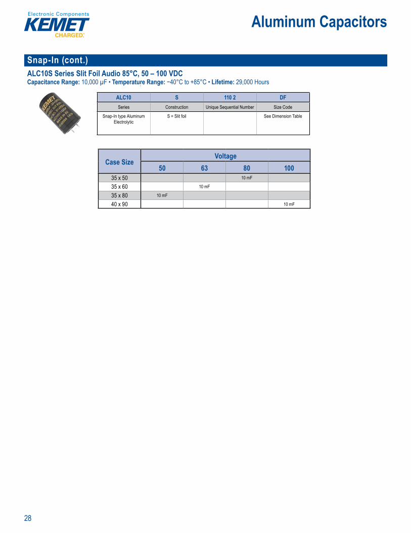
Snap-In (cont.)ALC10S Series Slit Foil Audio 85°C, 50 – 100 VDCCapacitance Range: 10,000 µF • Temperature Range: −40°C to +85°C • Lifetime: 29,000 Hours
Par Number System
ALC10 S 110 2 DFSeries Construction Unique Sequential Number Size Code
Snap-In type Aluminum Electrolytic
S = Slit foil See Dimension Table
Case SizeVoltage
50 63 80 10035 x 50 10 mF
35 x 60 10 mF
35 x 80 10 mF
40 x 90 10 mF

29
Aluminum Capacitors
Snap-In (cont.) ALC40 Series High Ripple Current 105°C, 25 – 500 VDCCapacitance Range: 47 to 120,000 µF • Temperature Range: −40°C to +105°C • Lifetime: 14,000 Hours
Pa t Num r System
ALC40 A 822 BB 025Series Termination Capacitance Code (µF) Size Code Voltage (VDC)
Snap-In type Aluminum Electrolytic
See Termination Table First two digits equals fi rst two signifi cant fi gures, third digit is the
number of additional zeros.
See Dimension Table 025 = 25040 = 40063 = 63100 = 100200 = 200
250 = 250350 = 350400 = 400450 = 450500 = 500
Case SizeVoltage
25 40 63 100 200 250 350 400 450 50025 x 30 8.2 mF 3.9 mF 2.2 mF 820 µF 270 µF 220 µF 120 µF 100 µF 47 µF 56 µF
25 x 35 10 mF 5.6 mF 3.3 mF 1 mF 390 µF 270 µF 150 µF 120 µF 56 µF 68 µF
25 x 40 12 mF 6.8 mF 3.9 mF 1 2 mF 470 µF 330 µF 180 µF 150 µF 68 µF 82 µF
30 x 30 12 mF 5.6 mF 3.9 mF 1 2 mF 470 µF 330 µF 180 µF 150 µF 68 µF 82 µF
30 x 35 15 mF 6.8 mF – 8.2 mF 4.7 mF 1 5 mF 560 µF 390 µF 220 µF 180 µF 82 µF 120 µF
30 x 40 18 mF 10 mF 5.6 mF 1.8 mF 680 µF 470 µF 270 µF 220 µF 100 µF
30 x 50 27 mF 12 mF 6.8 mF – 8.2 mF 2.2 mF 820 µF 560 µF 390 µF 330 µF 150 µF 180 µF
35 x 35 22 mF 12 mF 6.8 mF 2.2 mF 820 µF 560 µF 330 µF 270 µF 120 µF 150 µF
35 x 40 27 mF 15 mF 8.2 mF 2.7 mF 1 mF 680 µF 390 µF 330 µF 150 µF 180 µF
35 x 45 470 µF
35 x 50 33 mF – 0.039 F 18 mF 10 mF 3.3 mF 1.2 mF 820 µF 470 µF – 560 µF 390 µF – 470 µF 180 µF – 330 µF 270 µF
35 x 60 1 mF 560 µF 470 µF 330 µF – 470 µF 330 µF
35 x 80 1.5 mF 820 µF 680 µF 470 µF 470 µF
40 x 30 27 mF 12 mF 5.6 mF 2.2 mF 680 µF 470 µF 270 µF 220 µF 150 µF 180 µF
40 x 35 33 mF 6.8 mF 820 µF 560 µF 270 µF 180 µF 220 µF
40 x 40 39 mF 15 mF 8.2 mF 2.7 mF 1 mF 680 µF 390 µF 330 µF 220 µF 270 µF
40 x 45 18 mF 10 mF 3.3 mF 1.2 mF 820 µF 470 µF 390 µF
40 x 50 47 mF 22 mF 12 mF 3.9 mF 1.5 mF 1 mF 560 µF 470 µF 270 µF 390 µF
40 x 55 56 mF 27 mF 4.7 mF 1.2 mF 560 µF 330 µF 470 µF
40 x 60 15 mF 5.6 mF 1.8 mF 680 µF 680 µF 390 µF
40 x 80 82 mF 47 mF 22 mF 8.2 mF 2.7 mF 1.8 mF 1 mF 1 mF 560 µF – 820 µF 680 µF
40 x 105 120 mF 68 mF 33 mF 10 mF 3.9 mF 2.7 mF 1.5 mF 1.2 mF 820 µF 820 µF
45 x 105 5.6 mF 3.9 mF 2.2 mF 1.8 mF 1.2 mF 1 mF
50 x 105 6.8 mF 4.7 mF 2.7 mF 2.2 mF 1.5 mF 1.2 mF
30
Aluminum Capacitors
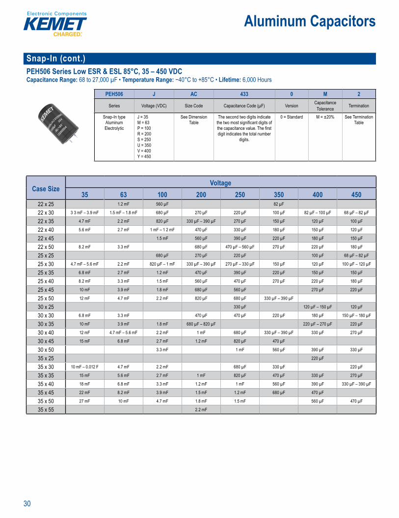
Snap-In (cont.)PEH506 Series Low ESR & ESL 85°C, 35 – 450 VDCCapacitance Range: 68 to 27,000 µF • Temperature Range: −40°C to +85°C • Lifetime: 6,000 Hours
Part Number System
PEH506 J AC 433 0 M 2
Series Voltage (VDC) Size Code Capacitance Code (µF) Version Capacitance Tolerance Termination
Snap-In type Aluminum Electrolytic
J = 35M = 63P = 100R = 200S = 250U = 350V = 400Y = 450
See Dimension Table
The second two digits indicate the two most signifi cant digits of the capacitance value. The fi rst digit indicates the total number
digits.
0 = Standard M = ±20% See Termination Table
Case SizeVoltage
35 63 100 200 250 350 400 45022 x 25 1.2 mF 560 µF 82 µF
22 x 30 3 3 mF – 3.9 mF 1.5 mF – 1.8 mF 680 µF 270 µF 220 µF 100 µF 82 µF – 100 µF 68 µF – 82 µF
22 x 35 4.7 mF 2.2 mF 820 µF 330 µF – 390 µF 270 µF 150 µF 120 µF 100 µF
22 x 40 5.6 mF 2.7 mF 1 mF – 1 2 mF 470 µF 330 µF 180 µF 150 µF 120 µF
22 x 45 1.5 mF 560 µF 390 µF 220 µF 180 µF 150 µF
22 x 50 8.2 mF 3.3 mF 680 µF 470 µF – 560 µF 270 µF 220 µF 180 µF
25 x 25 680 µF 270 µF 220 µF 100 µF 68 µF – 82 µF
25 x 30 4.7 mF – 5.6 mF 2.2 mF 820 µF – 1 mF 330 µF – 390 µF 270 µF – 330 µF 150 µF 120 µF 100 µF – 120 µF
25 x 35 6.8 mF 2.7 mF 1.2 mF 470 µF 390 µF 220 µF 150 µF 150 µF
25 x 40 8.2 mF 3.3 mF 1.5 mF 560 µF 470 µF 270 µF 220 µF 180 µF
25 x 45 10 mF 3.9 mF 1.8 mF 680 µF 560 µF 270 µF 220 µF
25 x 50 12 mF 4.7 mF 2.2 mF 820 µF 680 µF 330 µF – 390 µF
30 x 25 330 µF 120 µF – 150 µF 120 µF
30 x 30 6.8 mF 3.3 mF 470 µF 470 µF 220 µF 180 µF 150 µF – 180 µF
30 x 35 10 mF 3.9 mF 1.8 mF 680 µF – 820 µF 220 µF – 270 µF 220 µF
30 x 40 12 mF 4.7 mF – 5.6 mF 2.2 mF 1 mF 680 µF 330 µF – 390 µF 330 µF 270 µF
30 x 45 15 mF 6.8 mF 2.7 mF 1.2 mF 820 µF 470 µF
30 x 50 3.3 mF 1 mF 560 µF 390 µF 330 µF
35 x 25 220 µF
35 x 30 10 mF – 0.012 F 4.7 mF 2.2 mF 680 µF 330 µF 220 µF
35 x 35 15 mF 5.6 mF 2.7 mF 1 mF 820 µF 470 µF 330 µF 270 µF
35 x 40 18 mF 6.8 mF 3.3 mF 1.2 mF 1 mF 560 µF 390 µF 330 µF – 390 µF
35 x 45 22 mF 8.2 mF 3.9 mF 1.5 mF 1.2 mF 680 µF 470 µF
35 x 50 27 mF 10 mF 4.7 mF 1.8 mF 1.5 mF 560 µF 470 µF
35 x 55 2.2 mF
31
Aluminum Capacitors
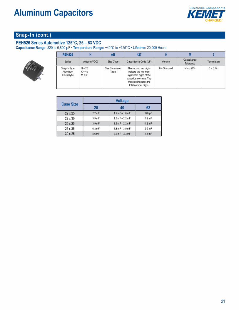
Snap-In (cont.)PEH526 Series Automotive 125°C, 25 – 63 VDCCapacitance Range: 820 to 6,800 µF • Temperature Range: −40°C to +125°C • Lifetime: 20,000 Hours
P rt e Sy e
PEH526 H AB 427 0 M 3
Series Voltage (VDC) Size Code Capacitance Code (µF) Version CapacitanceTolerance Termination
Snap-In type Aluminum Electrolytic
H = 25K = 40M = 63
See Dimension Table
The second two digits indicate the two most signifi cant digits of the capacitance value. The fi rst digit indicates the
total number digits.
0 = Standard M = ±20% 3 = 3 Pin
Case SizeVoltage
25 40 6322 x 25 2.7 mF 1.2 mF – 1.8 mF 820 µF
22 x 30 3 9 mF 1.5 mF – 2.2 mF 1.2 mF
25 x 25 3 9 mF 1.5 mF – 2.2 mF 1.2 mF
25 x 35 6.8 mF 1.8 mF – 3.9 mF 2 2 mF
30 x 25 5.6 mF 2.2 mF – 3.3 mF 1.8 mF
32
Aluminum Capacitors
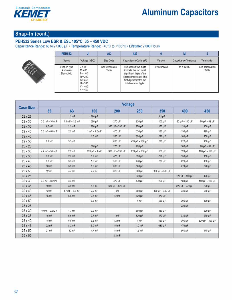
Snap-In (cont.)PEH532 Series Low ESR & ESL 105°C, 35 – 450 VDCCapacitance Range: 68 to 27,000 µF • Temperature Range: −40°C to +105°C • Lifetime: 2,000 Hours
Part Number System
PEH532 J AC 433 0 M 2
Series Voltage (VDC) Size Code Capacitance Code (µF) Version Capacitance Tolerance Termination
Snap-In type Aluminum Electrolytic
J = 35M = 63P = 100R = 200S = 250U = 350V = 400Y = 450
See Dimension Table
The second two digits indicate the two most signifi cant digits of the capacitance value. The fi rst digit indicates the
total number digits.
0 = Standard M = ±20% See Termination Table
Case SizeVoltage
35 63 100 200 250 350 400 45022 x 25 1.2 mF 560 µF 82 µF
22 x 30 3 3 mF – 3.9 mF 1.5 mF – 1.8 mF 680 µF 270 µF 220 µF 100 µF 82 µF – 100 µF 68 µF – 82 µF
22 x 35 4.7 mF 2.2 mF 820 µF 330 µF – 390 µF 270 µF 150 µF 120 µF 100 µF
22 x 40 5.6 mF – 6.8 mF 2.7 mF 1 mF – 1 2 mF 470 µF 330 µF 180 µF 150 µF 120 µF
22 x 45 1.5 mF 560 µF 390 µF 220 µF 180 µF 150 µF
22 x 50 8.2 mF 3.3 mF 680 µF 470 µF – 560 µF 270 µF 220 µF 180 µF
25 x 25 680 µF 270 µF 220 µF 100 µF 68 µF – 82 µF
25 x 30 4.7 mF – 5.6 mF 2.2 mF 820 µF – 1 mF 330 µF – 390 µF 270 µF – 330 µF 150 µF 120 µF 100 µF – 120 µF
25 x 35 6.8 mF 2.7 mF 1.2 mF 470 µF 390 µF 220 µF 150 µF 150 µF
25 x 40 8.2 mF 3.3 mF 1.5 mF 560 µF 470 µF 270 µF 220 µF 180 µF
25 x 45 10 mF 3.9 mF 1.8 mF 680 µF 560 µF 270 µF 220 µF
25 x 50 12 mF 4.7 mF 2.2 mF 820 µF 680 µF 330 µF – 390 µF
30 x 25 330 µF 120 µF – 150 µF 120 µF
30 x 30 6.8 mF – 8.2 mF 3.3 mF 470 µF 470 µF 220 µF 180 µF 150 µF – 180 µF
30 x 35 10 mF 3.9 mF 1.8 mF 680 µF – 820 µF 220 µF – 270 µF 220 µF
30 x 40 12 mF 4.7 mF – 5.6 mF 2.2 mF 1 mF 680 µF 330 µF – 390 µF 330 µF 270 µF
30 x 45 15 mF 6.8 mF 2.7 mF 1.2 mF 820 µF 470 µF
30 x 50 3.3 mF 1 mF 560 µF 390 µF 330 µF
35 x 25 220 µF
35 x 30 10 mF – 0.012 F 4.7 mF 2.2 mF 680 µF 330 µF 220 µF
35 x 35 15 mF 5.6 mF 2.7 mF 1 mF 820 µF 470 µF 330 µF 270 µF
35 x 40 18 mF 6.8 mF 3.3 mF 1.2 mF 1 mF 560 µF 390 µF 330 µF – 390 µF
35 x 45 22 mF 8.2 mF 3.9 mF 1.5 mF 1.2 mF 680 µF 470 µF
35 x 50 27 mF 10 mF 4.7 mF 1.8 mF 1.5 mF 560 µF 470 µF
35 x 55 2.2 mF

33
Aluminum Capacitors
Snap-In (cont.)PEH534 Series Low ESR & ESL 105°C, 35 – 450 VDC Capacitance Range: 150 to 22,000 µF • Temperature Range: −40°C to +105°C • Lifetime: 4,000 Hours
a t N r System
PEH534 J BC 456 0 M 2Series Voltage (VDC) Size Code Capacitance Code (µF) Version Capacitance Tolerance Termination
Snap-In type Aluminum Electrolytic
J = 35M = 63P = 100R = 200S = 250U = 350V = 400Y = 450
See Dimension Table
The second two digits indicate the two most signifi cant digits of the capacitance value. The fi rst digit indicates the
total number digits.
0 = Standard M = ±20% See Termination Table
Case SizeVoltage
35 63 100 200 250 350 400 45025 x 30 5.6 mF 2 2 mF
25 x 35 6.8 mF 470 µF 150 µF
25 x 40 8 2 mF 3 3 mF 1 5 mF 560 µF 390 µF 220 µF 150 µF
25 x 45 10 mF 680 µF 470 µF 220 µF
25 x 50 560 µF
30 x 25 6.8 mF 150 µF
30 x 30 8 2 mF 3 3 mF 1 5 mF 560 µF 390 µF 220 µF 150 µF
30 x 35 10 mF 680 µF 470 µF 220 µF
30 x 40 4.7 mF 2 2 mF 820 µF 560 µF 330 µF 220 µF
30 x 45 15 mF 5.6 mF 680 µF 390 µF 330 µF
30 x 50 6.8 mF 3 3 mF 1 mF 820 µF 390 µF 330 µF
35 x 25 8 2 mF 220 µF 150 µF
35 x 30 4.7 mF 2 2 mF 680 µF – 820 µF 470 µF 330 µF 220 µF 220 µF
35 x 35 15 mF 5.6 mF 1 mF 680 µF 390 µF 330 µF
35 x 40 6.8 mF 3 3 mF 820 µF 470 µF 390 µF 330 µF
35 x 45 8 2 mF 3 9 mF 1.5 mF 1 mF 560 µF 470 µF 390 µF
35 x 50 22 mF 10 mF 4.7 mF 560 µF 470 µF
34
Aluminum Capacitors
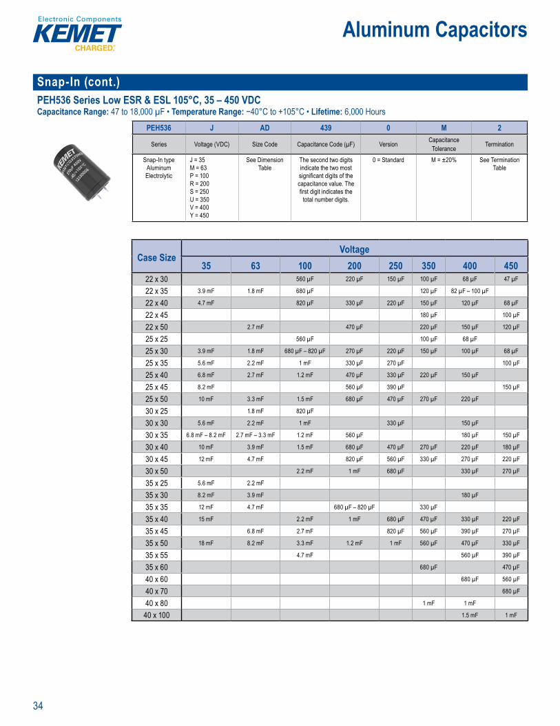
Snap-In (cont.)PEH536 Series Low ESR & ESL 105°C, 35 – 450 VDCCapacitance Range: 47 to 18,000 µF • Temperature Range: −40°C to +105°C • Lifetime: 6,000 Hours
P rt N be y te
PEH536 J AD 439 0 M 2
Series Voltage (VDC) Size Code Capacitance Code (µF) Version CapacitanceTolerance Termination
Snap-In type Aluminum Electrolytic
J = 35M = 63P = 100R = 200S = 250U = 350V = 400Y = 450
See Dimension Table
The second two digits indicate the two most signifi cant digits of the capacitance value. The fi rst digit indicates the
total number digits.
0 = Standard M = ±20% See Termination Table
Case SizeVoltage
35 63 100 200 250 350 400 45022 x 30 560 µF 220 µF 150 µF 100 µF 68 µF 47 µF
22 x 35 3.9 mF 1.8 mF 680 µF 120 µF 82 µF – 100 µF
22 x 40 4.7 mF 820 µF 330 µF 220 µF 150 µF 120 µF 68 µF
22 x 45 180 µF 100 µF
22 x 50 2.7 mF 470 µF 220 µF 150 µF 120 µF
25 x 25 560 µF 100 µF 68 µF
25 x 30 3.9 mF 1.8 mF 680 µF – 820 µF 270 µF 220 µF 150 µF 100 µF 68 µF
25 x 35 5.6 mF 2.2 mF 1 mF 330 µF 270 µF 100 µF
25 x 40 6.8 mF 2.7 mF 1.2 mF 470 µF 330 µF 220 µF 150 µF
25 x 45 8.2 mF 560 µF 390 µF 150 µF
25 x 50 10 mF 3.3 mF 1.5 mF 680 µF 470 µF 270 µF 220 µF
30 x 25 1.8 mF 820 µF
30 x 30 5.6 mF 2.2 mF 1 mF 330 µF 150 µF
30 x 35 6.8 mF – 8.2 mF 2.7 mF – 3.3 mF 1.2 mF 560 µF 180 µF 150 µF
30 x 40 10 mF 3.9 mF 1.5 mF 680 µF 470 µF 270 µF 220 µF 180 µF
30 x 45 12 mF 4.7 mF 820 µF 560 µF 330 µF 270 µF 220 µF
30 x 50 2.2 mF 1 mF 680 µF 330 µF 270 µF
35 x 25 5.6 mF 2.2 mF
35 x 30 8.2 mF 3.9 mF 180 µF
35 x 35 12 mF 4.7 mF 680 µF – 820 µF 330 µF
35 x 40 15 mF 2.2 mF 1 mF 680 µF 470 µF 330 µF 220 µF
35 x 45 6.8 mF 2.7 mF 820 µF 560 µF 390 µF 270 µF
35 x 50 18 mF 8.2 mF 3.3 mF 1.2 mF 1 mF 560 µF 470 µF 330 µF
35 x 55 4.7 mF 560 µF 390 µF
35 x 60 680 µF 470 µF
40 x 60 680 µF 560 µF
40 x 70 680 µF
40 x 80 1 mF 1 mF
40 x 100 1.5 mF 1 mF

35
Aluminum Capacitors
Snap-In (cont.)ELH Series Low Impedance 85°C, 6.3 – 450 VDCCapacitance Range: 47 to 120,000 µF • Temperature Range: −40°C to +85°C • Lifetime: 2,000 Hours
• , u ope at g li e• RoHS Complia t and lead-f
Pa t N y
ELH 159 M 6R3 A Q1 AA
Series Capacitance Code (pF) Tolerance Rated Voltage (VDC) Electrical Parameters Size Code Packaging
Snap-In Aluminum Electrolytic
Digits 4 – 5 represent the fi rst two digits of the capacitance value. The fi nal digit indicates
the number of zeros to be added.
M = ±20% 6R3 = 6.3010 = 10 016 = 16025 = 25035 = 35050 = 50063 = 63080 = 80
100 = 100160 = 160180 = 180200 = 200250 = 250350 = 350400 = 400450 = 450
A = Standard See Dimension Table
See Ordering Options Table
Case SizeVoltage
6.3 10 16 25 35 50 63 80 10022 x 25 15 mF 12 mF 8.2 mF 5.6 mF 3.9 mF 1.8 mF 1.2 mF 820 µF
22 x 30 18 mF – 0.022 F 15 mF 10 mF – 0.012 F 6.8 mF 4.7 mF 2.7 mF – 3.3 mF 2.2 mF 1.5 mF 1 mF
22 x 35 27 mF 18 mF 15 mF 8.2 mF 5.6 mF 3.9 mF 2.7 mF 1.8 mF 1.2 mF
22 x 40 33 mF 22 mF 18 mF 10 mF 6.8 mF 4.7 mF 3.3 mF 2.2 mF 1.5 mF
22 x 45 39 mF 27 mF 12 mF 8.2 mF 5.6 mF 3.9 mF 2.7 mF 1.8 mF
22 x 50 33 mF 22 mF 15 mF 10 mF 6.8 mF 4.7 mF 3.3 mF 2.2 mF
25 x 25 18 mF – 0.022 F 15 mF – 0.018 F 10 mF – 0.012 F 6.8 mF – 8.2 mF 4.7 mF – 5.6 mF 2.7 mF – 3.3 mF 2.2 mF 1.5 mF 1 mF
25 x 30 27 mF 22 mF 15 mF 10 mF 6.8 mF 3.9 mF 2.7 mF – 3.3 mF 1.8 mF – 2.2 mF 1.2 mF – 1.5 mF
25 x 35 33 mF 27 mF 18 mF 12 mF 8.2 mF 4.7 mF 3.9 mF 2.7 mF 1.8 mF
25 x 40 39 mF 33 mF 22 mF 15 mF 10 mF 5.6 mF – 6.8 mF 4.7 mF – 5.6 mF 3.3 mF 2.2 mF
25 x 45 47 mF 39 mF 27 mF 18 mF 12 mF 5.6 mF 3.9 mF 2.7 mF
25 x 50 56 mF 47 mF 15 mF 8.2 mF 4.7 mF 3.3 mF
30 x 25 27 mF 22 mF 15 mF 10 mF 6.8 mF 3.9 mF – 4.7 mF 2.7 mF – 3.3 mF 1.8 mF – 2.2 mF 1.5 mF
30 x 30 33 mF – 0.039 F 27 mF – 0.033 F 18 mF – 0.022 F 12 mF 8.2 mF – 0.01 F 5.6 mF – 6.8 mF 3.9 mF – 4.7 mF 2.7 mF – 3.3 mF 1.8 mF – 2.2 mF
30 x 35 47 mF 39 mF 27 mF 15 mF – 0.018 F 12 mF 6.8 mF 5.6 mF 3.9 mF 2.7 mF
30 x 40 56 mF 47 mF 33 mF 22 mF 15 mF 8.2 mF 6.8 mF 4.7 mF 3.3 mF
30 x 45 68 mF 56 mF 39 mF 27 mF 18 mF 10 mF 8.2 mF 5.6 mF 3.9 mF
30 x 50 82 mF 68 mF 47 mF 33 mF 22 mF 12 mF 10 mF 6.8 mF
35 x 25 33 mF – 0.039 F 33 mF 22 mF 12 mF 10 mF 5.6 mF 4.7 mF 2.7 mF – 3.3 mF 1.8 mF – 2.2 mF
35 x 30 47 mF – 0.056 F 39 mF – 0.047 F 27 mF – 0.033 F 15 mF – 0.018 F 12 mF 6.8 mF – 8.2 mF 5.6 mF – 6.8 mF 3.9 mF 2.7 mF – 3.3 mF
35 x 35 68 mF 56 mF 39 mF 22 mF 15 mF 10 mF 8.2 mF 4.7 mF – 5.6 mF 3.9 mF
35 x 40 82 mF 68 mF 47 mF 27 mF 18 mF 12 mF 10 mF 6.8 mF 4.7 mF
35 x 45 100 mF 56 mF 33 mF 22 mF 15 mF 12 mF 8.2 mF
35 x 50 120 mF 82 mF 68 mF 39 mF 27 mF 18 mF 10 mF 5.6 mF
36
Aluminum Capacitors
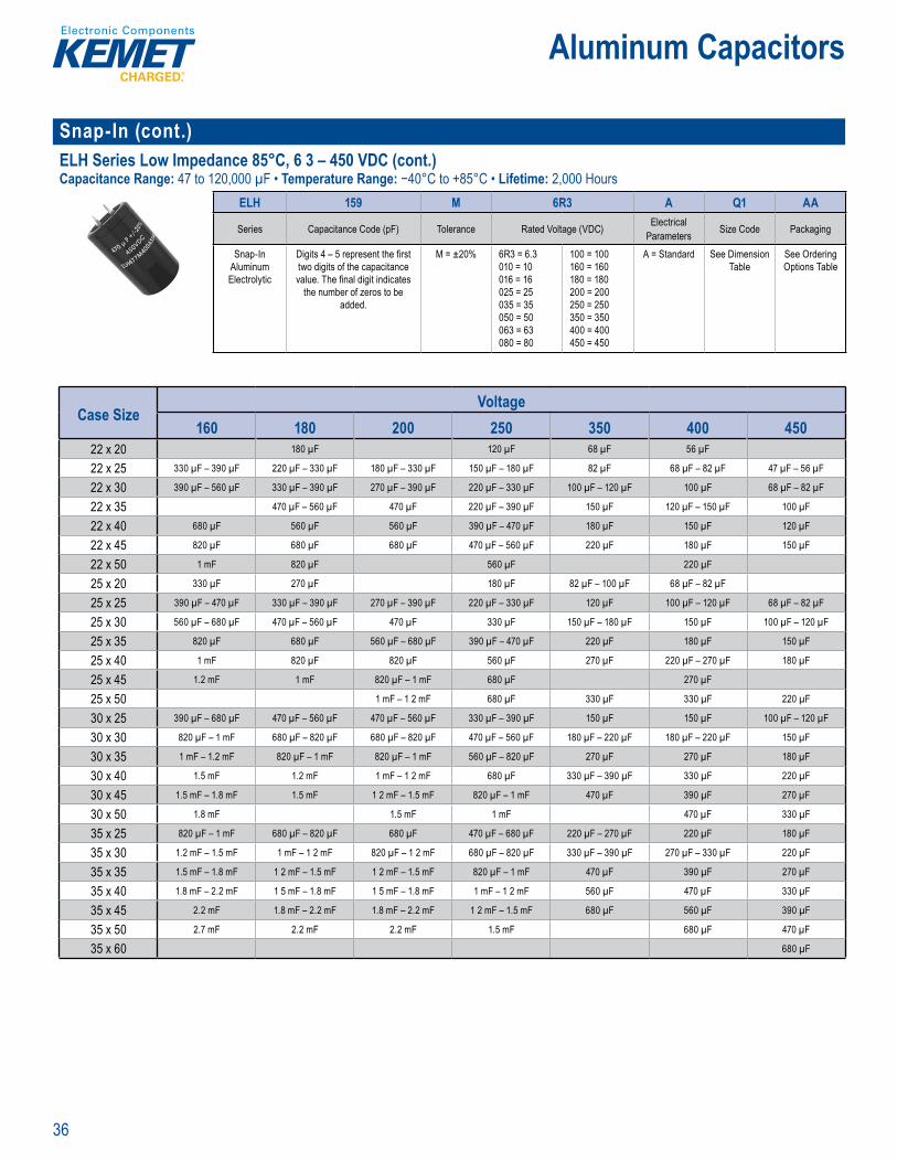
Snap-In (cont.)ELH Series Low Impedance 85°C, 6 3 – 450 VDC (cont.)Capacitance Range: 47 to 120,000 µF • Temperature Range: −40°C to +85°C • Lifetime: 2,000 Hours
Pa t N e S
ELH 159 M 6R3 A Q1 AA
Series Capacitance Code (pF) Tolerance Rated Voltage (VDC) Electrical Parameters Size Code Packaging
Snap-In Aluminum Electrolytic
Digits 4 – 5 represent the fi rst two digits of the capacitance value. The fi nal digit indicates
the number of zeros to be added.
M = ±20% 6R3 = 6.3010 = 10 016 = 16025 = 25035 = 35050 = 50063 = 63080 = 80
100 = 100160 = 160180 = 180200 = 200250 = 250350 = 350400 = 400450 = 450
A = Standard See Dimension Table
See Ordering Options Table
Case SizeVoltage
160 180 200 250 350 400 45022 x 20 180 µF 120 µF 68 µF 56 µF
22 x 25 330 µF – 390 µF 220 µF – 330 µF 180 µF – 330 µF 150 µF – 180 µF 82 µF 68 µF – 82 µF 47 µF – 56 µF
22 x 30 390 µF – 560 µF 330 µF – 390 µF 270 µF – 390 µF 220 µF – 330 µF 100 µF – 120 µF 100 µF 68 µF – 82 µF
22 x 35 470 µF – 560 µF 470 µF 220 µF – 390 µF 150 µF 120 µF – 150 µF 100 µF
22 x 40 680 µF 560 µF 560 µF 390 µF – 470 µF 180 µF 150 µF 120 µF
22 x 45 820 µF 680 µF 680 µF 470 µF – 560 µF 220 µF 180 µF 150 µF
22 x 50 1 mF 820 µF 560 µF 220 µF
25 x 20 330 µF 270 µF 180 µF 82 µF – 100 µF 68 µF – 82 µF
25 x 25 390 µF – 470 µF 330 µF – 390 µF 270 µF – 390 µF 220 µF – 330 µF 120 µF 100 µF – 120 µF 68 µF – 82 µF
25 x 30 560 µF – 680 µF 470 µF – 560 µF 470 µF 330 µF 150 µF – 180 µF 150 µF 100 µF – 120 µF
25 x 35 820 µF 680 µF 560 µF – 680 µF 390 µF – 470 µF 220 µF 180 µF 150 µF
25 x 40 1 mF 820 µF 820 µF 560 µF 270 µF 220 µF – 270 µF 180 µF
25 x 45 1.2 mF 1 mF 820 µF – 1 mF 680 µF 270 µF
25 x 50 1 mF – 1 2 mF 680 µF 330 µF 330 µF 220 µF
30 x 25 390 µF – 680 µF 470 µF – 560 µF 470 µF – 560 µF 330 µF – 390 µF 150 µF 150 µF 100 µF – 120 µF
30 x 30 820 µF – 1 mF 680 µF – 820 µF 680 µF – 820 µF 470 µF – 560 µF 180 µF – 220 µF 180 µF – 220 µF 150 µF
30 x 35 1 mF – 1.2 mF 820 µF – 1 mF 820 µF – 1 mF 560 µF – 820 µF 270 µF 270 µF 180 µF
30 x 40 1.5 mF 1.2 mF 1 mF – 1 2 mF 680 µF 330 µF – 390 µF 330 µF 220 µF
30 x 45 1.5 mF – 1.8 mF 1.5 mF 1 2 mF – 1.5 mF 820 µF – 1 mF 470 µF 390 µF 270 µF
30 x 50 1.8 mF 1.5 mF 1 mF 470 µF 330 µF
35 x 25 820 µF – 1 mF 680 µF – 820 µF 680 µF 470 µF – 680 µF 220 µF – 270 µF 220 µF 180 µF
35 x 30 1.2 mF – 1.5 mF 1 mF – 1 2 mF 820 µF – 1 2 mF 680 µF – 820 µF 330 µF – 390 µF 270 µF – 330 µF 220 µF
35 x 35 1.5 mF – 1.8 mF 1 2 mF – 1.5 mF 1 2 mF – 1.5 mF 820 µF – 1 mF 470 µF 390 µF 270 µF
35 x 40 1.8 mF – 2.2 mF 1 5 mF – 1.8 mF 1 5 mF – 1.8 mF 1 mF – 1 2 mF 560 µF 470 µF 330 µF
35 x 45 2.2 mF 1.8 mF – 2.2 mF 1.8 mF – 2.2 mF 1 2 mF – 1.5 mF 680 µF 560 µF 390 µF
35 x 50 2.7 mF 2.2 mF 2.2 mF 1.5 mF 680 µF 470 µF
35 x 60 680 µF
37
Aluminum Capacitors
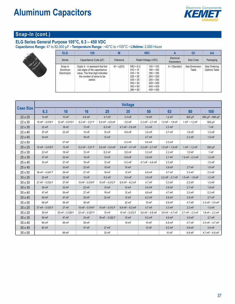
Snap-In (cont.)ELG Series General Purpose 105°C, 6.3 – 450 VDCCapacitance Range: 47 to 82,000 µF • Temperature Range: −40°C to +105°C • Lifetime: 2,000 Hours
• a t
Pa t N b S t
ELG 129 M 6R3 A Q1 AA
Series Capacitance Code (pF) Tolerance Rated Voltage (VDC) Electrical Parameters Size Code Packaging
Snap-In Aluminum Electrolytic
Digits 4 – 5 represent the fi rst two digits of the capacitance value. The fi nal digit indicates
the number of zeros to be added.
M = ±20% 6R3 = 6.3010 = 10 016 = 16025 = 25035 = 35050 = 50063 = 63080 = 80
100 = 100160 = 160180 = 180200 = 200250 = 250350 = 350400 = 400450 = 450
A = Standard See Dimension Table
See Ordering Options Table
Case SizeVoltage
6.3 10 16 25 35 50 63 80 10022 x 25 12 mF 10 mF 6.8 mF 4.7 mF 3.3 mF 1.8 mF 1.2 mF 820 µF 560 µF – 680 µF
22 x 30 15 mF – 0.018 F 12 mF – 0.015 F 8.2 mF – 0.01 F 5.6 mF – 6.8 mF 3.9 mF 2.2 mF – 2.7 mF 1.5 mF – 1.8 mF 1 mF – 1.2 mF 820 µF
22 x 35 22 mF 18 mF 12 mF 8.2 mF 4.7 mF – 5.6 mF 3.3 mF 2.2 mF 1 mF
22 x 40 27 mF 22 mF 15 mF 10 mF 6.8 mF 3.9 mF 2.7 mF 1.8 mF 1.2 mF
22 x 45 33 mF 18 mF 12 mF 4.7 mF 2.2 mF 1.5 mF
22 x 50 27 mF 8.2 mF 5.6 mF 3.3 mF
25 x 25 15 mF – 0.018 F 15 mF 8.2 mF – 0.01 F 5.6 mF – 6.8 mF 3.9 mF – 4.7 mF 2.2 mF – 2.7 mF 1.5 mF – 1.8 mF 1 mF – 1.2 mF 820 µF
25 x 30 22 mF 18 mF 12 mF 8.2 mF 5.6 mF 3.3 mF 2.2 mF 1.5 mF 1 mF
25 x 35 27 mF 22 mF 15 mF 10 mF 6.8 mF 3.9 mF 2.7 mF 1 5 mF – 2.2 mF 1.2 mF
25 x 40 33 mF 27 mF 18 mF 12 mF 8.2 mF 4.7 mF – 5.6 mF 3.3 mF 1.5 mF
25 x 45 33 mF 22 mF 15 mF 10 mF 3.9 mF 2.7 mF 1.8 mF
25 x 50 39 mF – 0.047 F 39 mF 27 mF 18 mF 12 mF 6.8 mF 4.7 mF 3.3 mF 2.2 mF
30 x 25 22 mF 22 mF 12 mF 8.2 mF 5.6 mF 3.9 mF 2.2 mF – 2.7 mF 1.5 mF – 1.8 mF 1.2 mF
30 x 30 27 mF – 0.033 F 27 mF 15 mF – 0.018 F 10 mF – 0.012 F 6.8 mF – 8.2 mF 4.7 mF 3.3 mF 2.2 mF 1.5 mF
30 x 35 39 mF 33 mF 22 mF 15 mF 10 mF 5.6 mF 3.9 mF 2.7 mF 1.8 mF
30 x 40 47 mF 39 mF 27 mF 18 mF 12 mF 6.8 mF 4.7 mF 3.3 mF 2.2 mF
30 x 45 56 mF 47 mF 33 mF 22 mF 15 mF 8.2 mF 5.6 mF 3.9 mF 2.7 mF
30 x 50 68 mF 56 mF 39 mF 22 mF 10 mF 6.8 mF 4.7 mF 3.3 mF – 3 9 mF
35 x 25 27 mF – 0.033 F 27 mF 15 mF – 0.018 F 10 mF – 0.012 F 6.8 mF – 8.2 mF 4.7 mF 3.3 mF 2.2 mF 1.5 mF
35 x 30 39 mF 33 mF – 0.039 F 22 mF – 0.027 F 15 mF 10 mF – 0.012 F 5.6 mF – 6.8 mF 3.9 mF – 4.7 mF 2.7 mF – 3.3 mF 1.8 mF – 2.2 mF
35 x 35 56 mF 47 mF 33 mF 18 mF – 0.022 F 15 mF 8.2 mF 5.6 mF 3.9 mF 2.7 mF
35 x 40 68 mF 56 mF 39 mF 18 mF 10 mF 6.8 mF 4.7 mF 3.3 mF – 4.7 mF
35 x 45 82 mF 47 mF 27 mF 12 mF 8.2 mF 5.6 mF 3.9 mF
35 x 50 68 mF 33 mF 10 mF 6.8 mF 4.7 mF – 6.8 mF
38
Aluminum Capacitors
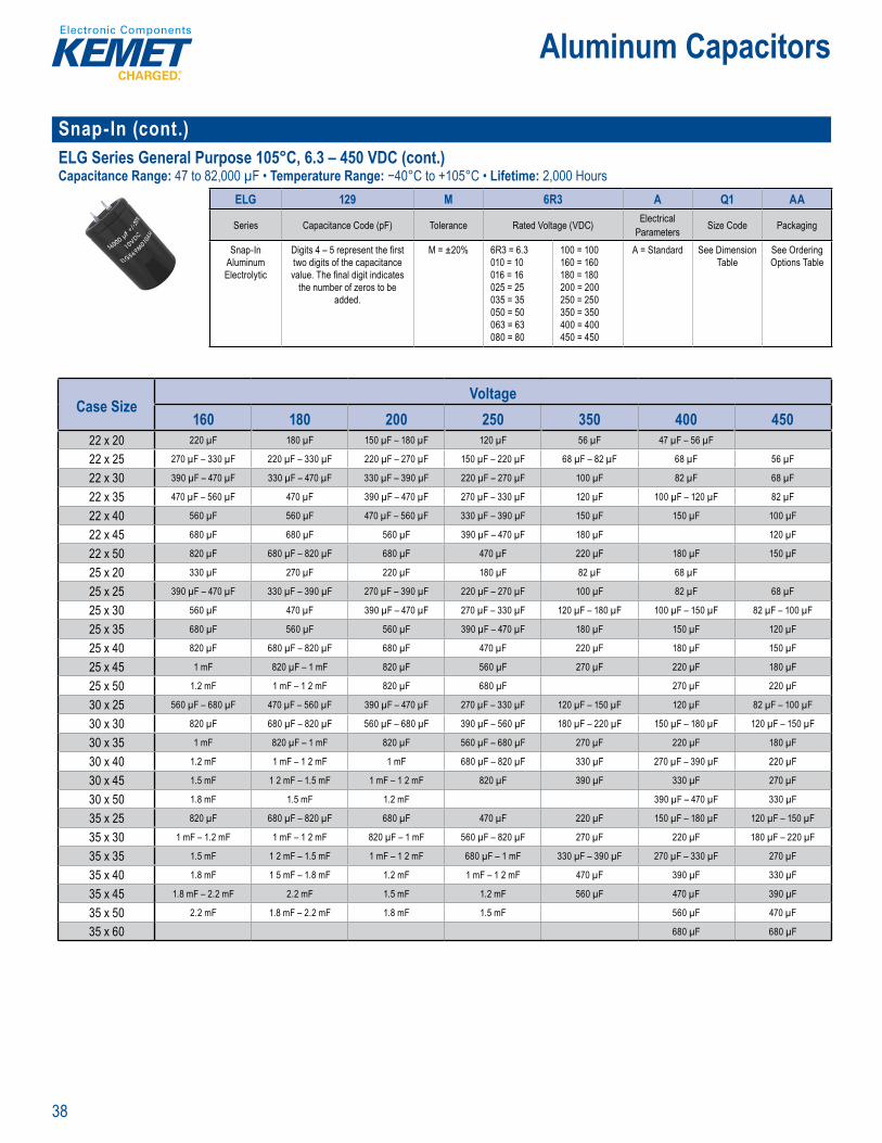
Snap-In (cont.)ELG Series General Purpose 105°C, 6.3 – 450 VDC (cont.)Capacitance Range: 47 to 82,000 µF • Temperature Range: −40°C to +105°C • Lifetime: 2,000 Hours
Pa t N b S t
ELG 129 M 6R3 A Q1 AA
Series Capacitance Code (pF) Tolerance Rated Voltage (VDC) Electrical Parameters Size Code Packaging
Snap-In Aluminum Electrolytic
Digits 4 – 5 represent the fi rst two digits of the capacitance value. The fi nal digit indicates
the number of zeros to be added.
M = ±20% 6R3 = 6.3010 = 10 016 = 16025 = 25035 = 35050 = 50063 = 63080 = 80
100 = 100160 = 160180 = 180200 = 200250 = 250350 = 350400 = 400450 = 450
A = Standard See Dimension Table
See Ordering Options Table
Case SizeVoltage
160 180 200 250 350 400 45022 x 20 220 µF 180 µF 150 µF – 180 µF 120 µF 56 µF 47 µF – 56 µF
22 x 25 270 µF – 330 µF 220 µF – 330 µF 220 µF – 270 µF 150 µF – 220 µF 68 µF – 82 µF 68 µF 56 µF
22 x 30 390 µF – 470 µF 330 µF – 470 µF 330 µF – 390 µF 220 µF – 270 µF 100 µF 82 µF 68 µF
22 x 35 470 µF – 560 µF 470 µF 390 µF – 470 µF 270 µF – 330 µF 120 µF 100 µF – 120 µF 82 µF
22 x 40 560 µF 560 µF 470 µF – 560 µF 330 µF – 390 µF 150 µF 150 µF 100 µF
22 x 45 680 µF 680 µF 560 µF 390 µF – 470 µF 180 µF 120 µF
22 x 50 820 µF 680 µF – 820 µF 680 µF 470 µF 220 µF 180 µF 150 µF
25 x 20 330 µF 270 µF 220 µF 180 µF 82 µF 68 µF
25 x 25 390 µF – 470 µF 330 µF – 390 µF 270 µF – 390 µF 220 µF – 270 µF 100 µF 82 µF 68 µF
25 x 30 560 µF 470 µF 390 µF – 470 µF 270 µF – 330 µF 120 µF – 180 µF 100 µF – 150 µF 82 µF – 100 µF
25 x 35 680 µF 560 µF 560 µF 390 µF – 470 µF 180 µF 150 µF 120 µF
25 x 40 820 µF 680 µF – 820 µF 680 µF 470 µF 220 µF 180 µF 150 µF
25 x 45 1 mF 820 µF – 1 mF 820 µF 560 µF 270 µF 220 µF 180 µF
25 x 50 1.2 mF 1 mF – 1 2 mF 820 µF 680 µF 270 µF 220 µF
30 x 25 560 µF – 680 µF 470 µF – 560 µF 390 µF – 470 µF 270 µF – 330 µF 120 µF – 150 µF 120 µF 82 µF – 100 µF
30 x 30 820 µF 680 µF – 820 µF 560 µF – 680 µF 390 µF – 560 µF 180 µF – 220 µF 150 µF – 180 µF 120 µF – 150 µF
30 x 35 1 mF 820 µF – 1 mF 820 µF 560 µF – 680 µF 270 µF 220 µF 180 µF
30 x 40 1.2 mF 1 mF – 1 2 mF 1 mF 680 µF – 820 µF 330 µF 270 µF – 390 µF 220 µF
30 x 45 1.5 mF 1 2 mF – 1.5 mF 1 mF – 1 2 mF 820 µF 390 µF 330 µF 270 µF
30 x 50 1.8 mF 1.5 mF 1.2 mF 390 µF – 470 µF 330 µF
35 x 25 820 µF 680 µF – 820 µF 680 µF 470 µF 220 µF 150 µF – 180 µF 120 µF – 150 µF
35 x 30 1 mF – 1.2 mF 1 mF – 1 2 mF 820 µF – 1 mF 560 µF – 820 µF 270 µF 220 µF 180 µF – 220 µF
35 x 35 1.5 mF 1 2 mF – 1.5 mF 1 mF – 1 2 mF 680 µF – 1 mF 330 µF – 390 µF 270 µF – 330 µF 270 µF
35 x 40 1.8 mF 1 5 mF – 1.8 mF 1.2 mF 1 mF – 1 2 mF 470 µF 390 µF 330 µF
35 x 45 1.8 mF – 2.2 mF 2.2 mF 1.5 mF 1.2 mF 560 µF 470 µF 390 µF
35 x 50 2.2 mF 1.8 mF – 2.2 mF 1.8 mF 1.5 mF 560 µF 470 µF
35 x 60 680 µF 680 µF

39
Aluminum Capacitors
Solder Pin/Tag ALP20 and ALT20/21 Series Low ESR 85°C, 40 – 450 VDCCapacitance Range: 22 to 150,000 µF • Temperature Range: −40°C to +85°C • Lifetime: 26,000 Hours
Pa t Numb r System
ALP 20A 682 AB 010Series Version Capacitance Code (µF) Size Code Voltage (VDC)
ALP = Solder pin ALT = Solder tag
20A = Standard 21A = Threaded Mounting Stud (ALT only)
First two digits represent signifi cant fi gures. Third digit specifi es number of zeros.
See Dimension Table 040 = 40063 = 63100 = 100200 = 200
250 = 250385 = 385400 = 400450 = 450
ALP20
Case SizeVoltage
40 63 100 250 400 45025 x 45 2.2 mF
30 x 45 2.2 mF 100 µF
35 x 45 4.7 mF 3 3 mF
35 x 55 6.8 mF 4.7 mF
40 x 55 10 mF 6.8 mF
40 x 75 10 mF 4.7 mF 1 mF
40 x 105 15 mF 470 µF
ALT20/21
Case SizeVoltage
40 63 200 250 400 45025 x 35 1 mF
30 x 45 3.3 mF 100 µF 100 µF
35 x 45 4.7 mF
35 x 55 680 µF 220 µF
40 x 55 10 mF 680 µF

40
Aluminum Capacitors
Solder Pin/Tag (cont.)ALP22 and ALT22/23 Series High Ripple 85°C, 40 – 450 VDCCapacitance Range: 22 to 150,000 µF • Temperature Range: −40°C to +85°C • Lifetime: 26,000 Hours
Pa t N mber Sy tem
ALP 22A 682 AB 010Series Version Capacitance Code (µF) Size Code Voltage (VDC)
ALP = Solder pin ALT = Solder tag
22A = Standard 23A = Threaded Mounting Stud (ALT only)
First two digits represent signifi cant fi gures. Third digit specifi es number of zeros.
See Dimension Table 040 = 40063 = 63100 = 100200 = 200
250 = 250385 = 385400 = 400450 = 450
ALP22
Case SizeVoltage
40 63 100 200 385 45025 x 45 4.7 mF 2.7 mF 1 mF 220 µF
30 x 45 6.8 mF 4.7 mF 100 µF
35 x 45 10 mF 220 µF
35 x 55 15 mF 10 mF 680 µF 220 µF
40 x 45 680 µF
40 x 55 22 mF 10 mF 4.7 mF 1 mF 470 µF
40 x 75 15 mF 680 µF 470 µF – 1 mF
40 x 105 10 mF 2.2 mF 1 mF 680 µF – 820 µF ALT22/23
Case SizeVoltage
40 63 100 200 38525 x 45 4.7 mF 1 mF 220 µF 100 µF
30 x 45 4.7 mF 150 µF
35 x 45 10 mF
35 x 55 15 mF 10 mF
40 x 45 680 µF
40 x 55 22 mF 4.7 mF 1 mF 470 µF
40 x 75 15 mF
40 x 105 10 mF 2.2 mF 1 mF
41
Aluminum Capacitors
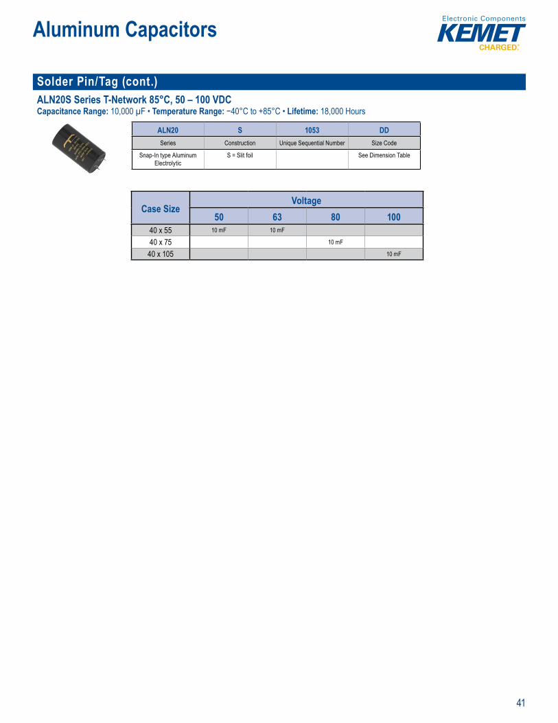
Solder Pin/Tag (cont.)ALN20S Series T-Network 85°C, 50 – 100 VDCCapacitance Range: 10,000 µF • Temperature Range: −40°C to +85°C • Lifetime: 18,000 Hours
Slit foil echnology Specifi ally d g e f a
Par Number ystem
ALN20 S 1053 DDSeries Construction Unique Sequential Number Size Code
Snap-In type Aluminum Electrolytic
S = Slit foil See Dimension Table
Case SizeVoltage
50 63 80 10040 x 55 10 mF 10 mF
40 x 75 10 mF
40 x 105 10 mF
42
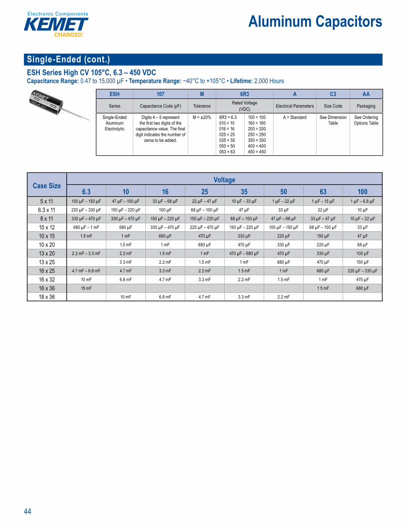
Aluminum Capacitors
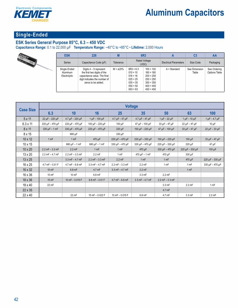
Single-Ended ESK Series General Purpose 85°C, 6.3 – 450 VDCCapacitance Range: 0.1 to 22,000 µF Temperature Range: −40°C to +85°C • Lifetime: 2,000 Hours
Part um er System
ESK 226 M 6R3 A C3 AA
Series Capacitance Code (pF) Tolerance Rated Voltage(VDC) Electrical Parameters Size Code Packaging
Single-Ended Aluminum Electrolytic
Digits 4 – 5 represent the fi rst two digits of the
capacitance value. The fi nal digit indicates the number of
zeros to be added.
M = ±20% 6R3 = 6.3010 = 10 016 = 16025 = 25035 = 35050 = 50063 = 63
100 = 100160 = 160200 = 200250 = 250350 = 350400 = 400450 = 450
A = Standard See Dimension Table
See Ordering Options Table
Case SizeVoltage
6.3 10 16 25 35 50 63 1005 x 11 22 µF – 220 µF 4.7 µF – 220 µF 1 µF – 100 µF 4.7 µF – 47 µF 4.7 µF – 47 µF 1 µF – 22 µF 1 µF – 10 µF 1 µF – 4.7 µF
6.3 x 11 220 µF – 470 µF 220 µF – 470 µF 100 µF – 220 µF 100 µF 47 µF – 100 µF 33 µF – 47 µF 22 µF – 47 µF 10 µF
8 x 11 330 µF – 1 mF 330 µF – 470 µF 220 µF – 470 µF 220 µF 100 µF – 220 µF 47 µF – 100 µF 33 µF – 47 µF 22 µF – 33 µF
8 x 15 680 µF 330 µF
10 x 12 1 mF 1 mF 470 µF 220 µF – 470 µF 220 µF – 330 µF 100 µF – 220 µF 100 µF 33 µF – 47 µF
10 x 15 680 µF – 1 mF 680 µF – 1 mF 330 µF – 470 µF 330 µF – 470 µF 220 µF – 330 µF 220 µF 47 µF
10 x 20 2.2 mF – 3.3 mF 2.2 mF 1 mF 1 mF 470 µF 330 µF – 470 µF 220 µF – 330 µF 100 µF
13 x 20 2.2 mF – 4.7 mF 2.2 mF – 3.3 mF 2.2 mF 1 mF 470 µF – 1 mF 470 µF 330 µF
13 x 25 3.3 mF – 4.7 mF 2 2 mF – 3.3 mF 2.2 mF 1 mF 1 mF 470 µF 220 µF – 330 µF
16 x 25 4.7 mF – 0.01 F 4.7 mF – 6.8 mF 3.3 mF – 4.7 mF 2.2 mF – 3.3 mF 2.2 mF 1 mF 1 mF 330 µF – 470 µF
16 x 32 10 mF 6.8 mF 4.7 mF 3.3 mF – 4.7 mF 2.2 mF 1 mF
16 x 36 15 mF 10 mF 6.8 mF 3.3 mF 2.2 mF
18 x 36 15 mF 10 mF – 0.015 F 6.8 mF – 0.01 F 4.7 mF – 6.8 mF 3 3 mF – 4.7 mF 2.2 mF – 3 3 mF
18 x 40 22 mF 3.3 mF 2.2 mF 1 mF
22 x 35 4.7 mF
22 x 40 22 mF 15 mF – 0.022 F 10 mF – 0.015 F 6.8 mF 4.7 mF 3 3 mF 2.2 mF
43
Aluminum Capacitors
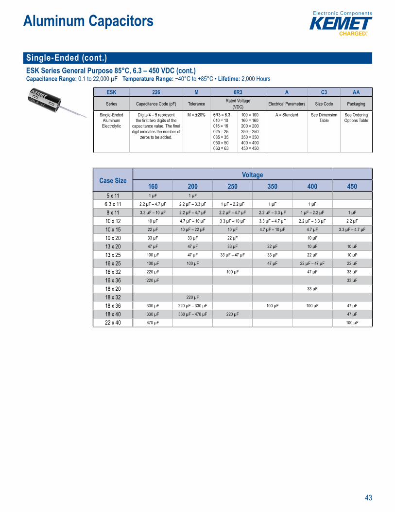
Single-Ended (cont.) ESK Series General Purpose 85°C, 6.3 – 450 VDC (cont.)Capacitance Range: 0.1 to 22,000 µF Temperature Range: −40°C to +85°C • Lifetime: 2,000 Hours
Part um er System
ESK 226 M 6R3 A C3 AA
Series Capacitance Code (pF) Tolerance Rated Voltage(VDC) Electrical Parameters Size Code Packaging
Single-Ended Aluminum Electrolytic
Digits 4 – 5 represent the fi rst two digits of the
capacitance value. The fi nal digit indicates the number of
zeros to be added.
M = ±20% 6R3 = 6.3010 = 10 016 = 16025 = 25035 = 35050 = 50063 = 63
100 = 100160 = 160200 = 200250 = 250350 = 350400 = 400450 = 450
A = Standard See Dimension Table
See Ordering Options Table
Case SizeVoltage
160 200 250 350 400 4505 x 11 1 µF 1 µF
6.3 x 11 2.2 µF – 4.7 µF 2.2 µF – 3.3 µF 1 µF – 2.2 µF 1 µF 1 µF
8 x 11 3.3 µF – 10 µF 2.2 µF – 4.7 µF 2.2 µF – 4.7 µF 2.2 µF – 3.3 µF 1 µF – 2.2 µF 1 µF
10 x 12 10 µF 4.7 µF – 10 µF 3 3 µF – 10 µF 3.3 µF – 4.7 µF 2.2 µF – 3.3 µF 2 2 µF
10 x 15 22 µF 10 µF – 22 µF 10 µF 4.7 µF – 10 µF 4.7 µF 3.3 µF – 4.7 µF
10 x 20 33 µF 33 µF 22 µF 10 µF
13 x 20 47 µF 47 µF 33 µF 22 µF 10 µF 10 µF
13 x 25 100 µF 47 µF 33 µF – 47 µF 33 µF 22 µF 10 µF
16 x 25 100 µF 100 µF 47 µF 22 µF – 47 µF 22 µF
16 x 32 220 µF 100 µF 47 µF 33 µF
16 x 36 220 µF 33 µF
18 x 20 33 µF
18 x 32 220 µF
18 x 36 330 µF 220 µF – 330 µF 100 µF 100 µF 47 µF
18 x 40 330 µF 330 µF – 470 µF 220 µF 47 µF
22 x 40 470 µF 100 µF
44
Aluminum Capacitors
Single-Ended (cont.) ESH Series High CV 105°C, 6.3 – 450 VDCCapacitance Range: 0.47 to 15,000 µF • Temperature Range: −40°C to +105°C • Lifetime: 2,000 Hours
art Num r Sys em
ESH 107 M 6R3 A C3 AA
Series Capacitance Code (pF) Tolerance Rated Voltage(VDC) Electrical Parameters Size Code Packaging
Single-Ended Aluminum Electrolytic
Digits 4 – 5 represent the fi rst two digits of the
capacitance value. The fi nal digit indicates the number of
zeros to be added.
M = ±20% 6R3 = 6.3010 = 10 016 = 16025 = 25035 = 35050 = 50063 = 63
100 = 100160 = 160200 = 200250 = 250350 = 350400 = 400450 = 450
A = Standard See Dimension Table
See Ordering Options Table
Case SizeVoltage
6.3 10 16 25 35 50 63 1005 x 11 100 µF – 150 µF 47 µF – 100 µF 33 µF – 68 µF 22 µF – 47 µF 10 µF – 33 µF 1 µF – 22 µF 1 µF – 15 µF 1 µF – 6.8 µF
6.3 x 11 220 µF – 330 µF 150 µF – 220 µF 100 µF 68 µF – 100 µF 47 µF 33 µF 22 µF 10 µF
8 x 11 330 µF – 470 µF 330 µF – 470 µF 150 µF – 220 µF 150 µF – 220 µF 68 µF – 100 µF 47 µF – 68 µF 33 µF – 47 µF 15 µF – 22 µF
10 x 12 680 µF – 1 mF 680 µF 330 µF – 470 µF 220 µF – 470 µF 150 µF – 220 µF 100 µF – 150 µF 68 µF – 100 µF 33 µF
10 x 15 1.5 mF 1 mF 680 µF 470 µF 330 µF 220 µF 150 µF 47 µF
10 x 20 1.5 mF 1 mF 680 µF 470 µF 330 µF 220 µF 68 µF
13 x 20 2.2 mF – 3.3 mF 2.2 mF 1.5 mF 1 mF 470 µF – 680 µF 470 µF 330 µF 100 µF
13 x 25 3 3 mF 2.2 mF 1.5 mF 1 mF 680 µF 470 µF 150 µF
16 x 25 4.7 mF – 6.8 mF 4.7 mF 3.3 mF 2.2 mF 1 5 mF 1 mF 680 µF 220 µF – 330 µF
16 x 32 10 mF 6.8 mF 4.7 mF 3.3 mF 2.2 mF 1.5 mF 1 mF 470 µF
16 x 36 15 mF 1 5 mF 680 µF
18 x 36 10 mF 6.8 mF 4.7 mF 3.3 mF 2.2 mF
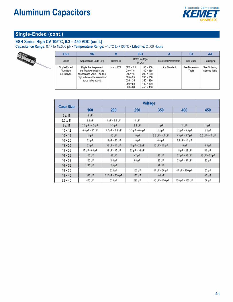
45
Aluminum Capacitors
Single-Ended (cont.) ESH Series High CV 105°C, 6.3 – 450 VDC (cont.)Capacitance Range: 0.47 to 15,000 µF • Temperature Range: −40°C to +105°C • Lifetime: 2,000 Hours
art Num r Sys em
ESH 107 M 6R3 A C3 AA
Series Capacitance Code (pF) Tolerance Rated Voltage(VDC) Electrical Parameters Size Code Packaging
Single-Ended Aluminum Electrolytic
Digits 4 – 5 represent the fi rst two digits of the
capacitance value. The fi nal digit indicates the number of
zeros to be added.
M = ±20% 6R3 = 6.3010 = 10 016 = 16025 = 25035 = 35050 = 50063 = 63
100 = 100160 = 160200 = 200250 = 250350 = 350400 = 400450 = 450
A = Standard See Dimension Table
See Ordering Options Table
Case SizeVoltage
160 200 250 350 400 4505 x 11 1 µF
6.3 x 11 2.2 µF 1 µF – 2.2 µF 1 µF
8 x 11 3.3 µF – 4.7 µF 3 3 µF 2 2 µF 1 µF 1 µF 1 µF
10 x 12 6.8 µF – 10 µF 4.7 µF – 6.8 µF 3 3 µF – 6.8 µF 2.2 µF 2.2 µF – 3.3 µF 2.2 µF
10 x 15 15 µF 10 µF 10 µF 3 3 µF – 4.7 µF 3.3 µF – 4.7 µF 3.3 µF – 4.7 µF
10 x 20 22 µF 15 µF – 22 µF 10 µF 6.8 µF 6.8 µF – 10 µF
13 x 20 33 µF 33 µF – 47 µF 15 µF – 22 µF 10 µF – 15 µF 10 µF 6.8 µF
13 x 25 47 µF – 68 µF 33 µF – 47 µF 22 µF – 33 µF 15 µF – 22 µF 10 µF
16 x 25 100 µF 68 µF 47 µF 22 µF 22 µF – 33 µF 15 µF – 22 µF
16 x 32 150 µF 100 µF 68 µF 33 µF 33 µF – 47 µF 22 µF
16 x 36 220 µF 150 µF 47 µF
18 x 36 220 µF 100 µF 47 µF – 68 µF 47 µF – 100 µF 33 µF
18 x 40 330 µF 220 µF – 330 µF 150 µF 100 µF 47 µF
22 x 40 470 µF 330 µF 220 µF 100 µF – 150 µF 100 µF – 150 µF 68 µF

46
Aluminum Capacitors
Single-Ended (cont.)ESC Series Low ESR 105°C, 6.3 – 100 VDCCapacitance Range: 4.7 to 15,000 µF • Temperature Range: −40°C to +105°C • Lifetime: 3,000 Hours
art N m e S te
ESC 157 M 6R3 A C3 AASeries Capacitance Code (pF) Tolerance Rated Voltage (VDC) Electrical Parameters Size Code Packaging
Single-Ended Aluminum Electrolytic
Digits 4 – 5 represent the fi rst two digits of the capacitance value. The fi nal digit indicates
the number of zeros to be added.
M = ±20% 6R3 = 6 3010 = 10 016 = 16025 = 25035 = 35050 = 50063 = 63100 = 100
A = Standard See Dimension Table
See Ordering Options Table
Case SizeVoltage
6.3 10 16 25 35 50 63 1005 x 11 150 µF 100 µF – 120 µF 68 µF – 100 µF 47 µF 4.7 µF – 33 µF 1 µF – 22 µF 4.7 µF – 15 µF 4.7 µF – 6.8 µF
6.3 x 11 220 µF 150 µF – 220 µF 120 µF – 150 µF 68 µF – 100 µF 47 µF – 68 µF 33 µF – 47 µF 22 µF – 33 µF 10 µF – 15 µF
8 x 11 330 µF – 470 µF 330 µF 220 µF 120 µF – 150 µF 100 µF – 120 µF 68 µF 47 µF – 68 µF 22 µF
8 x 15 680 µF 470 µF 330 µF 220 µF 150 µF 100 µF 33 µF
8 x 20 820 µF – 1 mF 1 mF 330 µF 220 µF 120 µF 100 µF
10 x 12 470 µF – 680 µF 470 µF 220 µF 150 µF
10 x 15 1.2 mF 820 µF 680 µF 470 µF 220 µF 120 µF – 150 µF 47 µF
10 x 20 1.5 mF 1.2 mF – 1 5 mF 820 µF – 1 mF 680 µF – 820 µF 330 µF – 470 µF 330 µF 220 µF 68 µF
13 x 20 2.2 mF 2.2 mF 1 2 mF – 1.5 mF 1 mF 680 µF – 820 µF 470 µF 330 µF 100 µF
13 x 25 3.3 mF 3 3 mF 2.2 mF 1.2 mF 1 mF 680 µF 470 µF 120 µF – 150 µF
16 x 25 4.7 mF 4.7 mF 3.3 mF 1.5 mF 1.2 mF – 1.5 mF 820 µF – 1 mF 680 µF 220 µF
16 x 32 6.8 mF – 8.2 mF 2.2 mF 2.2 mF 1.2 mF 820 µF – 1 mF 330 µF
16 x 36 10 mF 6.8 mF 4.7 mF 3.3 mF 2.2 mF 1.5 mF 1 2 mF
18 x 36 15 mF 8 2 mF 6.8 mF 4.7 mF 3.3 mF 1 5 mF 470 µF
18 x 40 2.2 mF
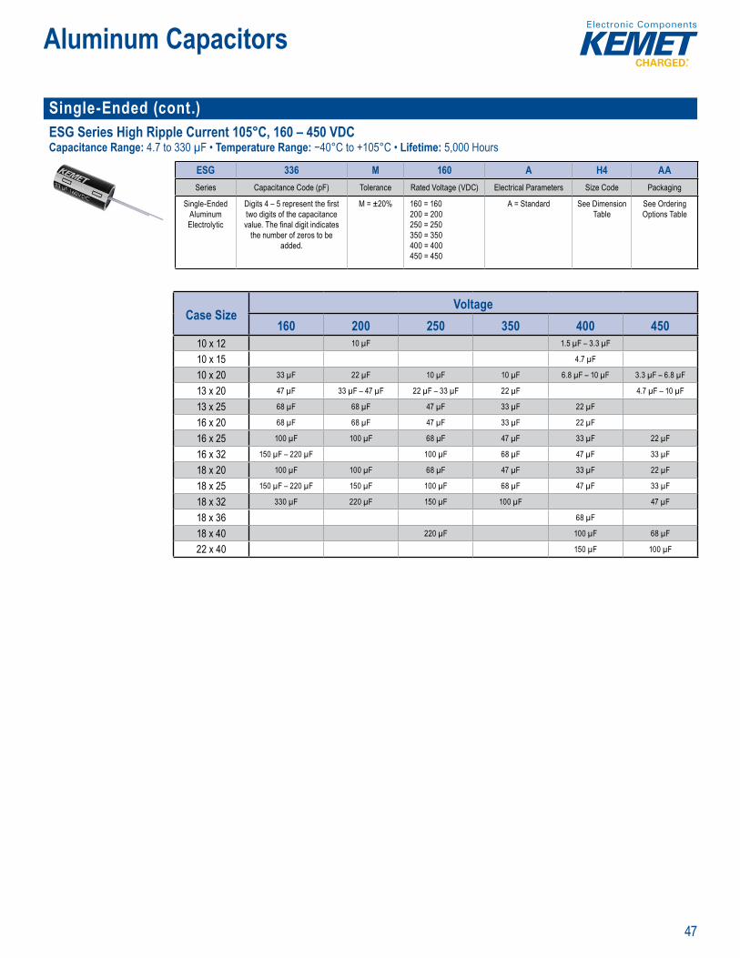
47
Aluminum Capacitors
Single-Ended (cont.)ESG Series High Ripple Current 105°C, 160 – 450 VDCCapacitance Range: 4.7 to 330 µF • Temperature Range: −40°C to +105°C • Lifetime: 5,000 Hours
ar N m er ys m
ESG 336 M 160 A H4 AASeries Capacitance Code (pF) Tolerance Rated Voltage (VDC) Electrical Parameters Size Code Packaging
Single-Ended Aluminum Electrolytic
Digits 4 – 5 represent the fi rst two digits of the capacitance value. The fi nal digit indicates
the number of zeros to be added.
M = ±20% 160 = 160200 = 200250 = 250350 = 350400 = 400450 = 450
A = Standard See Dimension Table
See Ordering Options Table
Case SizeVoltage
160 200 250 350 400 45010 x 12 10 µF 1.5 µF – 3.3 µF
10 x 15 4.7 µF
10 x 20 33 µF 22 µF 10 µF 10 µF 6.8 µF – 10 µF 3.3 µF – 6.8 µF
13 x 20 47 µF 33 µF – 47 µF 22 µF – 33 µF 22 µF 4.7 µF – 10 µF
13 x 25 68 µF 68 µF 47 µF 33 µF 22 µF
16 x 20 68 µF 68 µF 47 µF 33 µF 22 µF
16 x 25 100 µF 100 µF 68 µF 47 µF 33 µF 22 µF
16 x 32 150 µF – 220 µF 100 µF 68 µF 47 µF 33 µF
18 x 20 100 µF 100 µF 68 µF 47 µF 33 µF 22 µF
18 x 25 150 µF – 220 µF 150 µF 100 µF 68 µF 47 µF 33 µF
18 x 32 330 µF 220 µF 150 µF 100 µF 47 µF
18 x 36 68 µF
18 x 40 220 µF 100 µF 68 µF
22 x 40 150 µF 100 µF

48
Aluminum Capacitors
Single-Ended (cont.)ESY Series Low Impedance 105°C, 6.3 – 100 VDCCapacitance Range: 5.6 to 6,800 µF • Temperature Range: −40°C to +105°C • Lifetime: 5,000 Hours
Part u b r st m
ESY 396 M 6R3 A B2 AASeries Capacitance Code (pF) Tolerance Rated Voltage (VDC) Electrical Parameters Size Code Packaging
Single-Ended Aluminum Electrolytic
Digits 4 – 5 represent the fi rst two digits of the capacitance value. The fi nal digit indicates
the number of zeros to be added.
M = ±20% 6R3 = 6 3010 = 10 016 = 16025 = 25035 = 35050 = 50063 = 63100 = 100
A = Standard See Dimension Table
See Ordering Options Table
Case SizeVoltage
6.3 10 16 25 35 50 63 1004 x 7 39 µF 27 µF 18 µF 15 µF 10 µF 5.6 µF
5 x 7 47 µF – 68 µF 33 µF – 56 µF 27 µF – 33 µF 18 µF – 27 µF 15 µF – 18 µF 6.8 µF – 10 µF
5 x 11 100 µF – 150 µF 68 µF – 100 µF 39 µF – 56 µF 33 µF – 47 µF 27 µF – 33 µF 15 µF – 22 µF 15 µF 6.8 µF
6.3 x 7 100 µF – 150 µF 120 µF 68 µF 56 µF 39 µF 15 µF – 22 µF
6.3 x 11 270 µF – 330 µF 220 µF 100 µF – 120 µF 68 µF – 100 µF 47 µF – 56 µF 39 µF – 56 µF 22 µF – 33 µF 10 µF – 15 µF
8 x 7 180 µF – 220 µF 100 µF – 120 µF 68 µF – 100 µF 47 µF – 56 µF 27 µF – 33 µF
8 x 9 150 µF – 180 µF
8 x 11 470 µF – 560 µF 270 µF – 470 µF 150 µF – 330 µF 120 µF – 220 µF 68 µF – 150 µF 68 µF – 100 µF 39 µF – 56 µF 22 µF – 27 µF
8 x 14 680 µF 33 µF
8 x 16 820 µF 560 µF – 680 µF 470 µF 270 µF – 330 µF 180 µF – 220 µF 120 µF 68 µF – 82 µF 39 µF
8 x 20 1.2 mF 820 µF – 1 mF 560 µF – 680 µF 470 µF 270 µF 180 µF 120 µF 56 µF
10 x 12 1 mF 560 µF – 680 µF 470 µF 270 µF – 330 µF 180 µF – 220 µF 150 µF 68 µF – 82 µF 47 µF
10 x 15 1.2 mF 820 µF – 1 mF 560 µF – 680 µF 470 µF 330 µF 220 µF 100 µF – 120 µF 68 µF
10 x 20 1.5 mF 1.2 mF 820 µF – 1 mF 560 µF – 680 µF 470 µF 270 µF 150 µF – 180 µF 82 µF
10 x 25 1.8 mF – 2.2 mF 1.5 mF 1.2 mF 820 µF 560 µF 330 µF 220 µF 100 µF
13 x 16 150 µF – 180 µF 82 µF
13 x 20 2.7 mF – 3.3 mF 1.8 mF – 2 2 mF 1.5 mF 1 mF 680 µF 390 µF – 470 µF 270 µF 120 µF
13 x 25 3.9 mF 2.7 mF – 3 3 mF 1.8 mF – 2.2 mF 1.2 mF – 1 5 mF 820 µF – 1 mF 560 µF 330 µF 150 µF – 180 µF
13 x 30 4.7 mF 3.9 mF 2.7 mF 1.8 mF 1.2 mF 680 µF 390 µF – 470 µF 220 µF
13 x 36 5.6 mF 4.7 mF 3.3 mF 2.2 mF 1.5 mF 820 µF 560 µF 270 µF
13 x 40 680 µF 330 µF
16 x 20 5.6 mF 3.9 mF 2.7 mF 1.8 mF 1.2 mF 820 µF 390 µF – 470 µF 220 µF
16 x 25 6.8 mF 5.6 mF 3.9 mF 2.7 mF 1.8 mF 560 µF 270 µF
16 x 32 1 mF 820 µF 390 µF
16 x 36 1 mF 470 µF
16 x 40 1.2 mF 560 µF
18 x 20 680 µF 270 µF
18 x 25 820 µF 390 µF
18 x 32 1 mF 470 µF
18 x 36 1.2 mF 560 µF
18 x 40 1.5 mF 680 µF
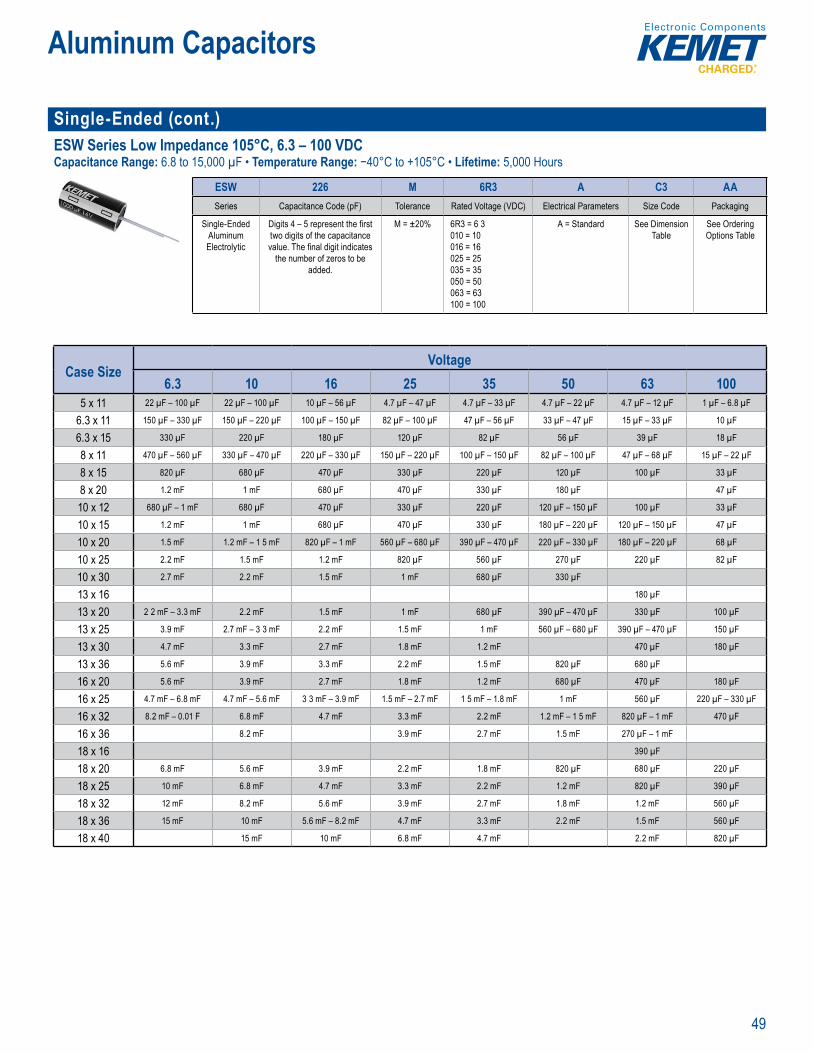
49
Aluminum Capacitors
Single-Ended (cont.) ESW Series Low Impedance 105°C, 6.3 – 100 VDCCapacitance Range: 6.8 to 15,000 µF • Temperature Range: −40°C to +105°C • Lifetime: 5,000 Hours
art m e S te
ESW 226 M 6R3 A C3 AASeries Capacitance Code (pF) Tolerance Rated Voltage (VDC) Electrical Parameters Size Code Packaging
Single-Ended Aluminum Electrolytic
Digits 4 – 5 represent the fi rst two digits of the capacitance value. The fi nal digit indicates
the number of zeros to be added.
M = ±20% 6R3 = 6 3010 = 10 016 = 16025 = 25035 = 35050 = 50063 = 63100 = 100
A = Standard See Dimension Table
See Ordering Options Table
Case SizeVoltage
6.3 10 16 25 35 50 63 1005 x 11 22 µF – 100 µF 22 µF – 100 µF 10 µF – 56 µF 4.7 µF – 47 µF 4.7 µF – 33 µF 4.7 µF – 22 µF 4.7 µF – 12 µF 1 µF – 6.8 µF
6.3 x 11 150 µF – 330 µF 150 µF – 220 µF 100 µF – 150 µF 82 µF – 100 µF 47 µF – 56 µF 33 µF – 47 µF 15 µF – 33 µF 10 µF
6.3 x 15 330 µF 220 µF 180 µF 120 µF 82 µF 56 µF 39 µF 18 µF
8 x 11 470 µF – 560 µF 330 µF – 470 µF 220 µF – 330 µF 150 µF – 220 µF 100 µF – 150 µF 82 µF – 100 µF 47 µF – 68 µF 15 µF – 22 µF
8 x 15 820 µF 680 µF 470 µF 330 µF 220 µF 120 µF 100 µF 33 µF
8 x 20 1.2 mF 1 mF 680 µF 470 µF 330 µF 180 µF 47 µF
10 x 12 680 µF – 1 mF 680 µF 470 µF 330 µF 220 µF 120 µF – 150 µF 100 µF 33 µF
10 x 15 1.2 mF 1 mF 680 µF 470 µF 330 µF 180 µF – 220 µF 120 µF – 150 µF 47 µF
10 x 20 1.5 mF 1.2 mF – 1 5 mF 820 µF – 1 mF 560 µF – 680 µF 390 µF – 470 µF 220 µF – 330 µF 180 µF – 220 µF 68 µF
10 x 25 2.2 mF 1.5 mF 1.2 mF 820 µF 560 µF 270 µF 220 µF 82 µF
10 x 30 2.7 mF 2.2 mF 1.5 mF 1 mF 680 µF 330 µF
13 x 16 180 µF
13 x 20 2 2 mF – 3.3 mF 2.2 mF 1.5 mF 1 mF 680 µF 390 µF – 470 µF 330 µF 100 µF
13 x 25 3.9 mF 2.7 mF – 3 3 mF 2.2 mF 1.5 mF 1 mF 560 µF – 680 µF 390 µF – 470 µF 150 µF
13 x 30 4.7 mF 3.3 mF 2.7 mF 1.8 mF 1.2 mF 470 µF 180 µF
13 x 36 5.6 mF 3.9 mF 3.3 mF 2.2 mF 1.5 mF 820 µF 680 µF
16 x 20 5.6 mF 3.9 mF 2.7 mF 1.8 mF 1.2 mF 680 µF 470 µF 180 µF
16 x 25 4.7 mF – 6.8 mF 4.7 mF – 5.6 mF 3 3 mF – 3.9 mF 1.5 mF – 2.7 mF 1 5 mF – 1.8 mF 1 mF 560 µF 220 µF – 330 µF
16 x 32 8.2 mF – 0.01 F 6.8 mF 4.7 mF 3.3 mF 2.2 mF 1.2 mF – 1 5 mF 820 µF – 1 mF 470 µF
16 x 36 8.2 mF 3.9 mF 2.7 mF 1.5 mF 270 µF – 1 mF
18 x 16 390 µF
18 x 20 6.8 mF 5.6 mF 3.9 mF 2.2 mF 1.8 mF 820 µF 680 µF 220 µF
18 x 25 10 mF 6.8 mF 4.7 mF 3.3 mF 2.2 mF 1.2 mF 820 µF 390 µF
18 x 32 12 mF 8.2 mF 5.6 mF 3.9 mF 2.7 mF 1.8 mF 1.2 mF 560 µF
18 x 36 15 mF 10 mF 5.6 mF – 8.2 mF 4.7 mF 3.3 mF 2.2 mF 1.5 mF 560 µF
18 x 40 15 mF 10 mF 6.8 mF 4.7 mF 2.2 mF 820 µF
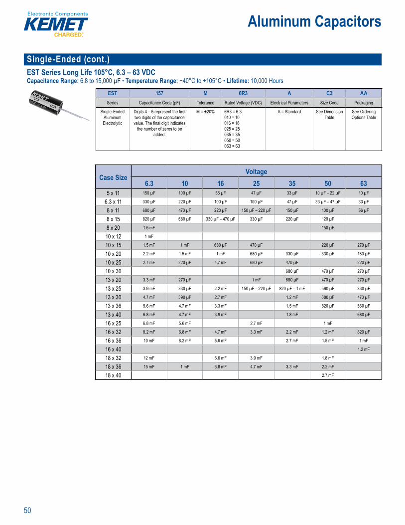
50
Aluminum Capacitors
Single-Ended (cont.)EST Series Long Life 105°C, 6.3 – 63 VDCCapacitance Range: 6.8 to 15,000 µF • Temperature Range: −40°C to +105°C • Lifetime: 10,000 Hours
art m e S te
EST 157 M 6R3 A C3 AASeries Capacitance Code (pF) Tolerance Rated Voltage (VDC) Electrical Parameters Size Code Packaging
Single-Ended Aluminum Electrolytic
Digits 4 – 5 represent the fi rst two digits of the capacitance value. The fi nal digit indicates
the number of zeros to be added.
M = ±20% 6R3 = 6 3010 = 10 016 = 16025 = 25035 = 35050 = 50063 = 63
A = Standard See Dimension Table
See Ordering Options Table
Case SizeVoltage
6.3 10 16 25 35 50 635 x 11 150 µF 100 µF 56 µF 47 µF 33 µF 10 µF – 22 µF 10 µF
6.3 x 11 330 µF 220 µF 100 µF 100 µF 47 µF 33 µF – 47 µF 33 µF
8 x 11 680 µF 470 µF 220 µF 150 µF – 220 µF 150 µF 100 µF 56 µF
8 x 15 820 µF 680 µF 330 µF – 470 µF 330 µF 220 µF 120 µF
8 x 20 1.5 mF 150 µF
10 x 12 1 mF
10 x 15 1.5 mF 1 mF 680 µF 470 µF 220 µF 270 µF
10 x 20 2.2 mF 1.5 mF 1 mF 680 µF 330 µF 330 µF 180 µF
10 x 25 2.7 mF 220 µF 4.7 mF 680 µF 470 µF 220 µF
10 x 30 680 µF 470 µF 270 µF
13 x 20 3.3 mF 270 µF 1 mF 680 µF 470 µF 270 µF
13 x 25 3.9 mF 330 µF 2.2 mF 150 µF – 220 µF 820 µF – 1 mF 560 µF 330 µF
13 x 30 4.7 mF 390 µF 2.7 mF 1.2 mF 680 µF 470 µF
13 x 36 5.6 mF 4.7 mF 3.3 mF 1.5 mF 820 µF 560 µF
13 x 40 6.8 mF 4.7 mF 3.9 mF 1.8 mF 680 µF
16 x 25 6.8 mF 5.6 mF 2.7 mF 1 mF
16 x 32 8.2 mF 6.8 mF 4.7 mF 3.3 mF 2.2 mF 1.2 mF 820 µF
16 x 36 10 mF 8.2 mF 5.6 mF 2.7 mF 1.5 mF 1 mF
16 x 40 1.2 mF
18 x 32 12 mF 5.6 mF 3.9 mF 1.8 mF
18 x 36 15 mF 1 mF 6.8 mF 4.7 mF 3.3 mF 2.2 mF
18 x 40 2.7 mF

51
Aluminum Capacitors
Single-Ended (cont.)EAK Series Long Life 125°C, 10 – 63 VDCCapacitance Range: 47 to 4,700 µF • Temperature Range: −40°C to +105°C • Lifetime: 5,000 Hours
Part b r
EAK 227 M 010 A G3 AASeries Capacitance Code (pF) Tolerance Rated Voltage (VDC) Electrical Parameters Size Code Packaging
Single-Ended Aluminum Electrolytic
Digits 4 – 5 represent the fi rst two digits of the capacitance value. The fi nal digit indicates
the number of zeros to be added.
M = ±20% 010 = 10 016 = 16025 = 25035 = 35050 = 50063 = 63
A = Standard See Dimension Table
See Ordering Options Table
Case SizeVoltage
10 16 25 35 50 63 160 200 250 350 400 4508 x 11 220 µF 220 µF 100 µF 47 µF 47 µF 3.3 µF 3.3 µF 2.2 µF 1 µF
8 x 16 1 µF
10 x 12 330 µF 330 µF 220 µF 100 µF 100 µF 4.7 µF 4.7 µF 3.3 µF 2.2 µF 1 µF
10 x 15 470 µF 330 µF 220 µF 100 µF 10 µF 4.7 µF 3.3 µF 2.2 µF – 3.3 µF 2.2 µF
10 x 20 1 mF 470 µF 470 µF 330 µF 220 µF 22 µF 10 µF 10 µF 4.7 µF 4.7 µF 3.3 µF
10 x 25 33 µF 22 µF 10 µF 10 µF 4.7 µF
13 x 20 1 mF 470 µF 330 µF 220 µF 47 µF 33 µF 22 µF 10 µF
13 x 25 2.2 mF 1 mF 470 µF 330 µF 68 µF 47 µF 33 µF 22 µF
13 x 30 22 µF
16 x 20 68 µF
16 x 25 3.3 mF 2 2 mF 1 mF 470 µF 100 µF 100 µF 47 µF 33 µF 33 µF 22 µF
16 x 32 4.7 mF 3 3 mF 2 2 mF 1 mF 150 µF 68 µF 47 µF 47 µF 33 µF
18 x 32 4.7 mF
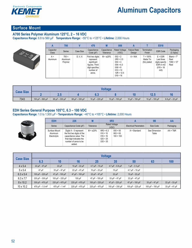
52
Aluminum Capacitors
Surface MountA700 Series Polymer Aluminum 125°C, 2 – 16 VDCCapacitance Range: 6.8 to 560 µF Temperature Range: −55°C to +125°C • Lifetime: 2,000 Hours
Order ng Info mation
A 700 V 476 M 006 A T E018Capacitor
Class Series Case Size Capacitance Code (pF)
Capacitance Tolerance
Rated Voltage (VDC)
Failure Rate/Design
Termination Finish ESR Code Packaging
(C-Spec)
A = Aluminum
700 = Aluminum Polymer
D, V, X First two digits represent signifi cant
fi gures. Third digit specifi es
number of zeros.
M = ±20% 002 = 2 2R5 = 2.5 004 = 4 006 = 6.3 008 = 8 010 = 10 12R = 12.5 016 = 16
A = N/A T = 100% Matte Tin
(Sn) plated
E = ESR Last three
digits specify ESR in mΩ (018 = 18
mΩ)
Blank = 7" Reel 7280 = 13" Reel
Case SizeVoltage
2 2.5 4 6.3 8 10 12.5 167343 100 µF – 560 µF 68 µF – 330 µF 68 µF – 330 µF 10 µF – 220 µF 10 µF – 100 µF 10 µF – 150 µF 10 µF – 100 µF 6.8 µF – 22 µF
EDH Series General Purpose 105°C, 6.3 – 100 VDCCapacitance Range: 1.0 to 1,500 µF • Temperature Range: −40°C to +105°C • Lifetime: 2,000 Hours
nefi ts
E ET' ED f l t c cit esi ned fo i d n t i t rc i b ds
p a i
art u ber Sys em
EDH 226 M 6R3 A 9B AASeries Capacitance Code (pF) Tolerance Rated Voltage
(VDC) Electrical Parameters Size Code Packaging
Surface Mount Aluminum Electrolytic
Digits 4 – 5 represent the fi rst two digits of the capacitance value. The fi nal digit indicates the number of zeros to be
added.
M = ±20% 6R3 = 6.3010 = 10 016 = 16025 = 25035 = 35
050 = 50063 = 63100 = 100
A = Standard See Dimension Table
AA = T&R
Case SizeVoltage
6.3 10 16 25 35 50 63 1004 x 5.4 22 µF – 47 µF 22 µF 10 µF – 22 µF 4.7 µF – 10 µF 4.7 µF – 6.8 µF 1 µF – 3 3 µF
5 x 5.4 47 µF 33 µF – 47 µF 22 µF – 47 µF 10 µF – 22 µF 10 µF 4.7 µF – 10 µF
6.3 x 5.4 100 µF – 220 µF 47 µF – 100 µF 47 µF – 100 µF 22 µF – 47 µF 22 µF 10 µF – 22 µF
6.3 x 7.7 220 µF – 330 µF 100 µF – 220 µF 100 µF 47 µF – 100 µF 33 µF – 47 µF 22 µF – 47 µF
8 x 10.2 330 µF – 470 µF 220 µF – 470 µF 220 µF – 470 µF 100 µF – 220 µF 47 µF – 220 µF 47 µF – 100 µF 33 µF – 47 µF 22 µF – 33 µF
10 x 10.2 470 µF – 1.5 mF 470 µF – 1 mF 220 µF – 470 µF 220 µF – 470 µF 100 µF – 330 µF 100 µF – 220 µF 100 µF – 150 µF 33 µF – 47 µF
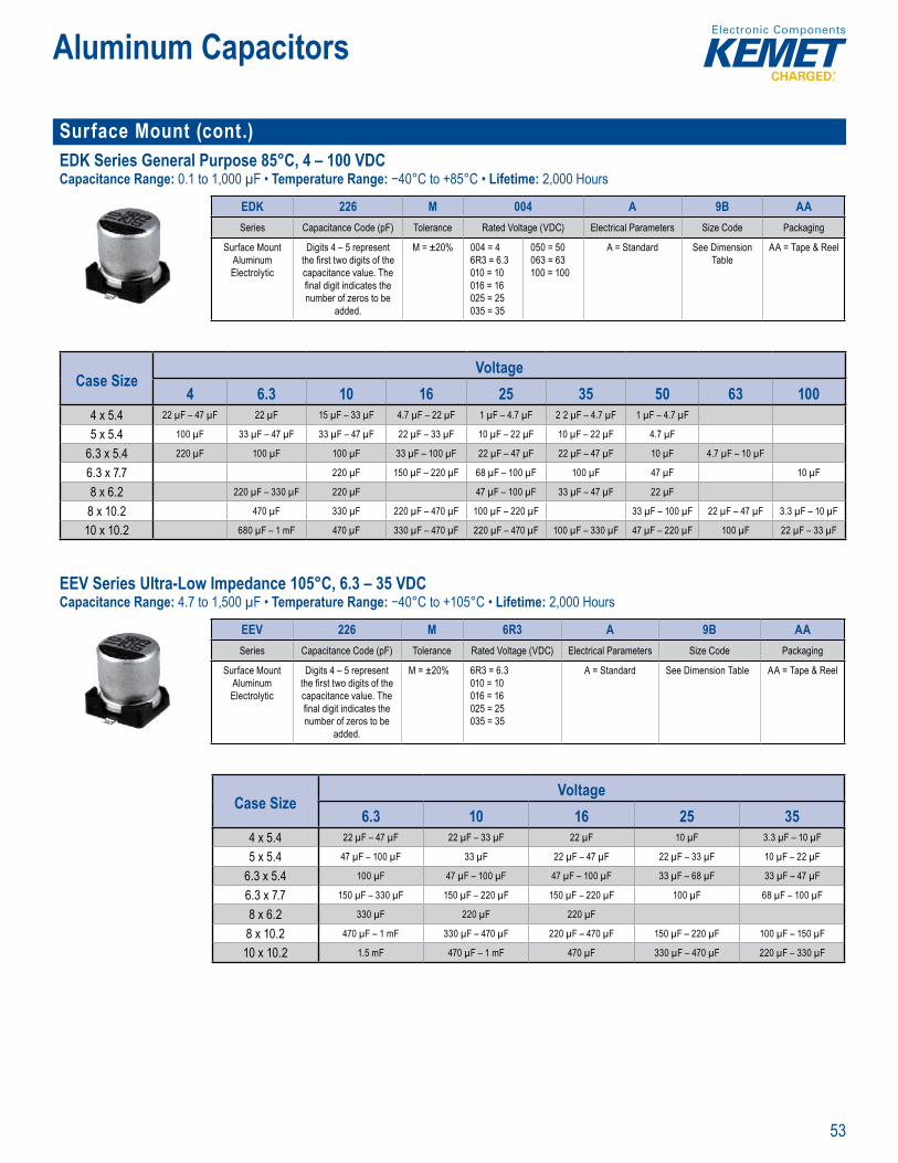
53
Aluminum Capacitors
Surface Mount (cont.)EDK Series General Purpose 85°C, 4 – 100 VDCCapacitance Range: 0.1 to 1,000 µF • Temperature Range: −40°C to +85°C • Lifetime: 2,000 Hours
art u b r Sys
EDK 226 M 004 A 9B AASeries Capacitance Code (pF) Tolerance Rated Voltage (VDC) Electrical Parameters Size Code Packaging
Surface Mount Aluminum Electrolytic
Digits 4 – 5 represent the fi rst two digits of the capacitance value. The fi nal digit indicates the number of zeros to be
added.
M = ±20% 004 = 46R3 = 6.3010 = 10 016 = 16025 = 25035 = 35
050 = 50063 = 63100 = 100
A = Standard See Dimension Table
AA = Tape & Reel
Case SizeVoltage
4 6.3 10 16 25 35 50 63 1004 x 5.4 22 µF – 47 µF 22 µF 15 µF – 33 µF 4.7 µF – 22 µF 1 µF – 4.7 µF 2 2 µF – 4.7 µF 1 µF – 4.7 µF
5 x 5.4 100 µF 33 µF – 47 µF 33 µF – 47 µF 22 µF – 33 µF 10 µF – 22 µF 10 µF – 22 µF 4.7 µF
6.3 x 5.4 220 µF 100 µF 100 µF 33 µF – 100 µF 22 µF – 47 µF 22 µF – 47 µF 10 µF 4.7 µF – 10 µF
6.3 x 7.7 220 µF 150 µF – 220 µF 68 µF – 100 µF 100 µF 47 µF 10 µF
8 x 6.2 220 µF – 330 µF 220 µF 47 µF – 100 µF 33 µF – 47 µF 22 µF
8 x 10.2 470 µF 330 µF 220 µF – 470 µF 100 µF – 220 µF 33 µF – 100 µF 22 µF – 47 µF 3.3 µF – 10 µF
10 x 10.2 680 µF – 1 mF 470 µF 330 µF – 470 µF 220 µF – 470 µF 100 µF – 330 µF 47 µF – 220 µF 100 µF 22 µF – 33 µF
EEV Series Ultra-Low Impedance 105°C, 6.3 – 35 VDCCapacitance Range: 4.7 to 1,500 µF • Temperature Range: −40°C to +105°C • Lifetime: 2,000 Hours
fi v i 2
vie
T's s f alumi m elec t c surf nt acitors are ned for plication qui ng lt ow edance a rofi le ertic ch
T ic l t l l ( i c mm ns and s it e power su s ( MPS)
Surface
erie , 05 C
art u b r Sys
EEV 226 M 6R3 A 9B AASeries Capacitance Code (pF) Tolerance Rated Voltage (VDC) Electrical Parameters Size Code Packaging
Surface Mount Aluminum Electrolytic
Digits 4 – 5 represent the fi rst two digits of the capacitance value. The fi nal digit indicates the number of zeros to be
added.
M = ±20% 6R3 = 6.3010 = 10 016 = 16025 = 25035 = 35
A = Standard See Dimension Table AA = Tape & Reel
Case SizeVoltage
6.3 10 16 25 354 x 5.4 22 µF – 47 µF 22 µF – 33 µF 22 µF 10 µF 3.3 µF – 10 µF
5 x 5.4 47 µF – 100 µF 33 µF 22 µF – 47 µF 22 µF – 33 µF 10 µF – 22 µF
6.3 x 5.4 100 µF 47 µF – 100 µF 47 µF – 100 µF 33 µF – 68 µF 33 µF – 47 µF
6.3 x 7.7 150 µF – 330 µF 150 µF – 220 µF 150 µF – 220 µF 100 µF 68 µF – 100 µF
8 x 6.2 330 µF 220 µF 220 µF
8 x 10.2 470 µF – 1 mF 330 µF – 470 µF 220 µF – 470 µF 150 µF – 220 µF 100 µF – 150 µF
10 x 10.2 1.5 mF 470 µF – 1 mF 470 µF 330 µF – 470 µF 220 µF – 330 µF
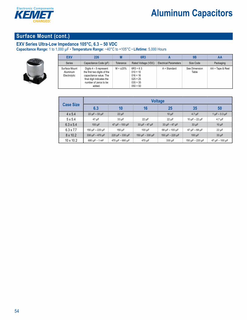
54
Aluminum Capacitors
Surface Mount (cont.)EXV Series Ultra-Low Impedance 105°C, 6.3 – 50 VDCCapacitance Range: 1 to 1,000 µF • Temperature Range: −40°C to +105°C • Lifetime: 5,000 Hours
Par N mber System
EXV 226 M 6R3 A 9B AASeries Capacitance Code (pF) Tolerance Rated Voltage (VDC) Electrical Parameters Size Code Packaging
Surface Mount Aluminum Electrolytic
Digits 4 – 5 represent the fi rst two digits of the capacitance value. The fi nal digit indicates the number of zeros to be
added.
M = ±20% 6R3 = 6 3010 = 10 016 = 16025 = 25035 = 35050 = 50
A = Standard See Dimension Table
AA = Tape & Reel
Case SizeVoltage
6.3 10 16 25 35 504 x 5.4 22 µF – 33 µF 22 µF 10 µF 4.7 µF 1 µF – 3.3 µF
5 x 5.4 47 µF 33 µF 22 µF 22 µF 10 µF – 22 µF 4.7 µF
6.3 x 5.4 100 µF 47 µF – 100 µF 33 µF – 47 µF 33 µF – 47 µF 33 µF 10 µF
6.3 x 7.7 150 µF – 220 µF 150 µF 100 µF 68 µF – 100 µF 47 µF – 68 µF 22 µF
8 x 10.2 330 µF – 470 µF 220 µF – 330 µF 150 µF – 330 µF 150 µF – 220 µF 100 µF 33 µF
10 x 10.2 680 µF – 1 mF 470 µF – 680 µF 470 µF 330 µF 150 µF – 220 µF 47 µF – 100 µF

55
Aluminum Capacitors
Motor Start MS/MD Series 60ºC/70°C, 120 – 260 VACCapacitance Range: 25 to 750 µF • Temperature Range: MS: −20°C to +60°C, MD: −20°C to +70°C • Lifetime: 500 Hours
Pa m e y t m
080 MS 12 AA M A 1 STDCapacitance Code
(µF) Rating Voltage (VAC) Size Code ManufacturingStyle
Capacitance Tolerance Terminal Code Version
Example:080 = 80 µF120 = 120 µF
MS = Motor start single ratingMD = Motor start dual rating
12 = 12022 = 22026 = 260
See Dimension Table
M = Molded case A = -0% +25% K = ±10%
1 = Double amp tag
STD = Standard
MS
Case SizeVoltage
120 VAC 220 VAC 260 VAC38 x 75 25 µF – 360 µF 20 µF – 70 µF 16 µF – 80 µF
38 x 90 85 µF – 510 µF 40 µF – 150 µF 35 µF – 100 µF
38 x 116 120 µF – 750 µF 55 µF – 200 µF 50 µF – 200 µF
MD
Case SizeVoltage
120 VAC 220 VAC 260 VAC38 x 75 25 µF – 360 µF 30 µF – 70 µF 25 µF – 55 µF
38 x 90 85 µF – 510 µF 40 µF – 100 µF 30 µF – 80 µF
38 x 116 120 µF – 750 µF 55 µF – 150 µF 45 µF – 115 µF
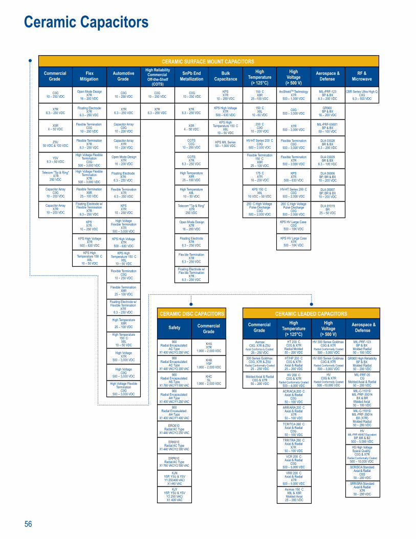
56
Ceramic Capacitors
CommercialGrade
FlexMitigation
AutomotiveGrade
High ReliabilityCommercial Off-the-Shelf
(COTS)
BulkCapacitance
HighVoltage
(> 500 V)
Aerospace &Defense
RF &Microwave
HighTemperature
(> 125°C)
SnPb EndMetallization
C0G10 – 250 VDC
X7R6.3 – 250 VDC
X5R4 – 50 VDC
Y5V6.3 – 50 VDC
Telecom "Tip & Ring" X7R
250 VDC
Capacitor ArrayC0G
10 – 200 VDC
Capacitor ArrayX7R
10 – 200 VDC
Z5U50 VDC & 100 VDC
C0G10 – 250 VDC
X7R6.3 – 250 VDC
X7R6.3 – 250 VDC
COTSC0G
10 – 200 VDC
COTSX7R
6.3 – 250 VDC
KPS High VoltageX7R
500 – 630 VDC
KPS MIL Series50 – 1,000 VDC
High TemperatureX8R
25 – 100 VDC
High TemperatureX8L
10 – 50 VDC
Telecom "Tip & Ring" X7R
250 VDC
Open Mode DesignX7R
16 – 200 VDC
Floating ElectrodeX7R
6.3 – 250 VDC
Flex ble TerminationX7R
6.3 – 250 VDC
Floating Electrode w/Flex ble Termination
X7R6.3 – 250 VDC
C0G10 – 250 VDC
X7R6.3 – 250 VDC
Capacitor ArrayC0G
10 – 200 VDC
Capacitor ArrayX7R
10 – 200 VDC
Open Mode DesignX7R
16 – 200 VDC
Flexible TerminationX7R
6.3 – 250 VDC
KPSX7R
10 – 250 VDC
High VoltageFlexible Termination
X7R500 – 3,000 VDC
KPS High VoltageX7R
500 – 630 VDC
KPS HighTemperature 150 C
X8L10 – 50 VDC
Flexible TerminationC0G
10 – 250 VDC
Flexible Termination X8R
25 – 100 VDC
High TemperatureX8R
25 – 100 VDC
High VoltageX7R
500 – 3,000 VDC
High Voltage FlexibleTermination
C0G500 – 3,000 VDC
High Temperature150 C
X8L10 – 50 VDC
Open Mode DesignX7R
16 – 200 VDC
Floating ElectrodeX7R
6.3 – 250 VDC
Flexible Termination C0G
10 – 250 VDC
Flexible TerminationX7R
6.3 – 250 VDC
High Voltage FlexibleTermination
C0G500 – 3,000 VDC
High Voltage FlexibleTermination
X7R500 – 3,000 VDC
Flexible TerminationX8R
25 – 100 VDC
Floating Electrode w/Flexible Termination
X7R6.3 – 250 VDC
KPS High VoltageX7R
500 – 630 VDC
C0G10 – 250 VDC
KPSX7R
10 – 250 VDC
ArcShieldTM TechnologyX7R
500 – 1,000 VDC
C0G500 – 3,000 VDC
X7R500 – 3,000 VDC
Flexible TerminationC0G
500 – 3,000 VDC
Flexible TerminationX7R
500 – 3,000 VDC
KPSX7R
500 – 630 VDC
HV-HT Series 200 CC0G
500 – 2,000 VDC
KPS HV Large Case C0G
500 – 10K VDC
KPS HV Large CaseX7R
500 – 10K VDC
200 C High VoltagePulse Discharge
C0G500 – 2,000 VDC
MIL-PRF-123BP & BX
6.3 – 200 VDC
GR900 BP & BX
16 – 200 VDC
MIL-PRF-55681 BP & BX
50 – 100 VDC
DLA 03028BR & BX
6.3 – 200 VDC
DLA 03029BR & BX
6.3 – 100 VDC
CBR Series Ultra High Q C0G
6.3 – 500 VDC
150 CX8R
25 –100 VDC
150 CX8L
10 –50 VDC
200 CC0G
10 – 200 VDC
HV-HT Series 200 CC0G
500 – 2,000 VDC
KPS 150 C X8L
10 VDC – 50 VDC
200 C High Voltage Pulse Discharge
C0G500 – 2,000 VDC
Flexible Termination150 C
X8R25 – 100 VDC
CERAMIC SURFACE MOUNT CAPACITORS
KPSX7R
10 – 250 VDC
KPS HighTemperature 150 C
X8L10 – 50 VDC
KPS HighTemperature 150 C
X8L10 – 50 VDC
Floating ElectrodeX7R
6.3 – 250 VDC
Floating Electrode w/Flexible Termination
X7R6.3 – 250 VDC
175 CX7R
16 – 200 VDC
DLA 05006BP, BR & BX
10 – 200 VDC
DLA 05007BP, BR & BX
10 – 200 VDC
DLA 91019BR
25 – 50 VDC
High VoltageC0G
500 – 3,000 VDC
X5R4 – 50 VDC
CERAMIC LEADED CAPACITORS
CommercialGrade
HighTemperature
(> 125°C)
HighVoltage
(> 500 V)
Aerospace &Defense
AximaxC0G, X7R & Z5U
Axial Conforma ly Coated 25 – 250 VDC
300 Series Goldmax C0G, X7R & Z5U
Radial Conformally Coated25 – 250 VDC
Molded Axial & RadialC0G & X7R
50 – 200 VDC
MIL-PRF-123BP & BX
Molded Radial50 – 100 VDC
GR900 High ReliabilityBP & BX
Molded Radial50 – 200 VDCMIL-PRF-20
CGMolded Axial & Radial
50 – 200 VDC
HVMIL-PRF-46467 Equivalent
BP, BR & BZ500 – 5,000 VDCHS High VoltageSpace Quality
C0G & X7RRadial Conformally Coated
500 – 10,000 VDC SCR/SCA Standard
Axial & RadialC0G
50 – 200 VDCSRR/SRA Standard
Axial & RadialX7R
50 – 200 VDC
MIL-C-11015/MIL-PRF-39014
BX & BRMolded Axial 50 – 100 VDCMIL-C-11015/
MIL-PRF-39014BX (X7R)
Molded Radial50 – 200 VDC
HV 300 Series Goldmax C0G & X7R
Radial Conformally Coated500 – 3,000 VDC
HVC0G & X7R
Radial Conformally Coated500 –10,000 VDC
HT/HP 200 CC0G & X7R
Axial & Radial25 – 200 VDC
HV 200 CC0G & X7R
Radial Conformally Coated500 – 4,000 VDCACR/ACA 200 C
Axial & RadialC0G
50 – 100 VDCARR/ARA 200 C
Axial & RadialX7R
50 – 100 VDCTCR/TCA 260 C
Axial & RadialC0G
50 – 100 VDCTRR/TRA 260 C
Axial & RadialX7R
50 – 100 VDCVCR 200 C
Axial & RadialC0G
500 – 5,000 VDCVRR 200 C
Axial & RadialX7R
500 – 5,000 VDCAximax 150 C
X8L & X8RMolded Axial
25 – 200 VDC
HT 200 CC0G & X7R
Radial Molded50 – 200 VDC
HV 600 Series Goldmax C0G & X7R
Radial Conformally Coated500 – 3,000 VDC
CERAMIC DISC CAPACITORS
Safety CommercialGrade
abil y
0
Ra a DC
14
900Radial Encapsulated
AC TypeX1 440 VAC/Y2 300 VAC
900Radial Encapsulated
AS TypeX1 760 VAC/Y1 500 VAC
900Radial Encapsulated
AH TypeX1 400 VAC/Y1 250 VAC
900Radial Encasulated
AH TypeX1 400 VAC/Y1 400 VAC
ERO610 Radial AC Type
X1 440 VAC/Y2 250 VAC
ERK610 Radial AC Type
X1 440 VAC/Y2 300 VAC
ERP610 Radial AC Type
X1 760 VAC/Y2 500 VAC
900Radial Encapsulated
AC TypeX1 400 VAC/Y2 250 VAC
KHAX7R
1,000 – 2,000 VDC
KHBY5P
1,000 – 2,000 VDC
KHCSL
1,000 – 2,000 VDC
KJNY5P, Y5U & Y5VY1 250/400 VAC/
X1 440 VACKJY
Y5P, Y5U & Y5VY2 250 VAC/X1 400 VAC
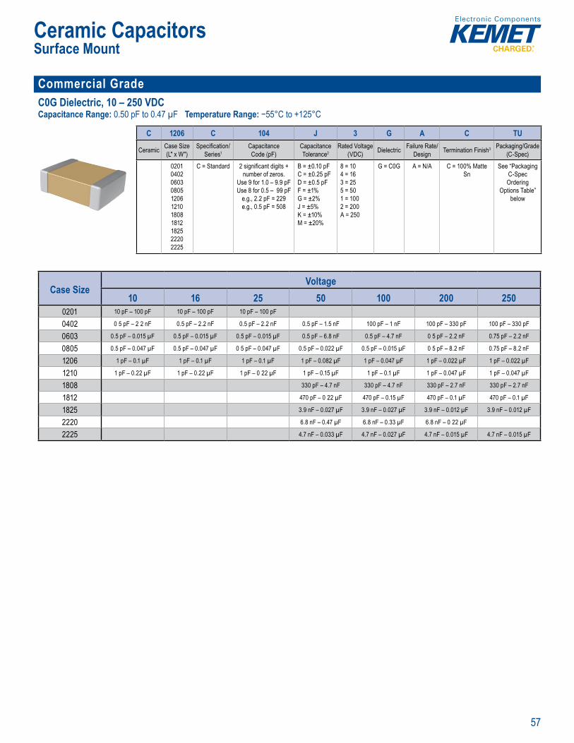
57
Ceramic CapacitorsSurface Mount
Commercial Grade C0G Dielectric, 10 – 250 VDCCapacitance Range: 0.50 pF to 0.47 µF Temperature Range: −55°C to +125°C
p , , ±2%, ±5%, • No piezo lectric ois
O dering In ormation
C 1206 C 104 J 3 G A C TU
Ceramic Case Size (L" x W")
Specifi cation/Series1
Capacitance Code (pF)
Capacitance Tolerance2
Rated Voltage (VDC) Dielectric Failure Rate/
Design Termination Finish3 Packaging/Grade (C-Spec)
02010402060308051206121018081812182522202225
C = Standard 2 signifi cant digits +number of zeros.
Use 9 for 1.0 – 9.9 pFUse 8 for 0.5 – 99 pF
e.g., 2.2 pF = 229e.g., 0.5 pF = 508
B = ±0.10 pFC = ±0.25 pFD = ±0.5 pFF = ±1%G = ±2%J = ±5%K = ±10%M = ±20%
8 = 104 = 163 = 255 = 501 = 100 2 = 200A = 250
G = C0G A = N/A C = 100% Matte Sn
See “Packaging C-Spec Ordering
Options Table” below
Case SizeVoltage
10 16 25 50 100 200 2500201 10 pF – 100 pF 10 pF – 100 pF 10 pF – 100 pF
0402 0 5 pF – 2 2 nF 0.5 pF – 2.2 nF 0.5 pF – 2.2 nF 0.5 pF – 1.5 nF 100 pF – 1 nF 100 pF – 330 pF 100 pF – 330 pF
0603 0.5 pF – 0.015 µF 0.5 pF – 0.015 µF 0.5 pF – 0.015 µF 0.5 pF – 6.8 nF 0.5 pF – 4.7 nF 0 5 pF – 2.2 nF 0.75 pF – 2.2 nF
0805 0.5 pF – 0.047 µF 0.5 pF – 0.047 µF 0 5 pF – 0.047 µF 0.5 pF – 0.022 µF 0.5 pF – 0.015 µF 0 5 pF – 8.2 nF 0.75 pF – 8.2 nF
1206 1 pF – 0.1 µF 1 pF – 0.1 µF 1 pF – 0.1 µF 1 pF – 0.082 µF 1 pF – 0.047 µF 1 pF – 0.022 µF 1 pF – 0.022 µF
1210 1 pF – 0.22 µF 1 pF – 0.22 µF 1 pF – 0 22 µF 1 pF – 0.15 µF 1 pF – 0.1 µF 1 pF – 0.047 µF 1 pF – 0.047 µF
1808 330 pF – 4.7 nF 330 pF – 4.7 nF 330 pF – 2.7 nF 330 pF – 2.7 nF
1812 470 pF – 0 22 µF 470 pF – 0.15 µF 470 pF – 0.1 µF 470 pF – 0.1 µF
1825 3.9 nF – 0.027 µF 3.9 nF – 0.027 µF 3.9 nF – 0.012 µF 3.9 nF – 0.012 µF
2220 6.8 nF – 0.47 µF 6.8 nF – 0.33 µF 6.8 nF – 0 22 µF
2225 4.7 nF – 0.033 µF 4.7 nF – 0.027 µF 4.7 nF – 0.015 µF 4.7 nF – 0.015 µF
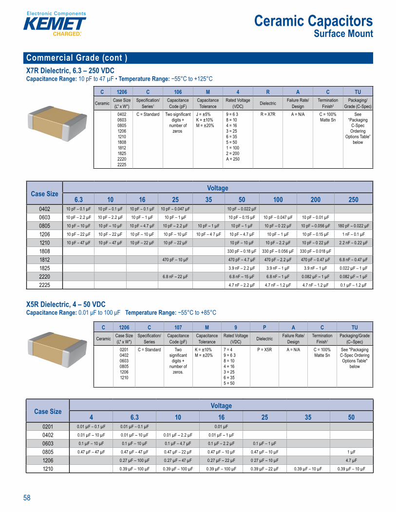
58
Ceramic CapacitorsSurface Mount
Commercial Grade (cont )X7R Dielectric, 6.3 – 250 VDCCapacitance Range: 10 pF to 47 µF • Temperature Range: −55°C to +125°C
O d r n
C 1206 C 106 M 4 R A C TU
Ceramic Case Size (L" x W")
Specifi cation/Series1
Capacitance Code (pF)
Capacitance Tolerance
Rated Voltage (VDC) Dielectric Failure Rate/
DesignTermination
Finish2Packaging/
Grade (C-Spec)0402060308051206121018081812182522202225
C = Standard Two signifi cant digits +
number of zeros
J = ±5%K = ±10%M = ±20%
9 = 6 3 8 = 10 4 = 16 3 = 25 6 = 35 5 = 50 1 = 100 2 = 200 A = 250
R = X7R A = N/A C = 100% Matte Sn
See “Packaging
C-Spec Ordering
Options Table” below
Case SizeVoltage
6.3 10 16 25 35 50 100 200 2500402 10 pF – 0.1 µF 10 pF – 0.1 µF 10 pF – 0.1 µF 10 pF – 0.047 µF 10 pF – 0.022 µF
0603 10 pF – 2.2 µF 10 pF – 2.2 µF 10 pF – 1 µF 10 pF – 1 µF 10 pF – 0.15 µF 10 pF – 0.047 µF 10 pF – 0.01 µF
0805 10 pF – 10 µF 10 pF – 10 µF 10 pF – 4.7 µF 10 pF – 2.2 µF 10 pF – 1 µF 10 pF – 1 µF 10 pF – 0 22 µF 10 pF – 0.056 µF 180 pF – 0.022 µF
1206 10 pF – 22 µF 10 pF – 22 µF 10 pF – 10 µF 10 pF – 10 µF 10 pF – 4 7 µF 10 pF – 4.7 µF 10 pF – 1 µF 10 pF – 0.15 µF 1 nF – 0.1 µF
1210 10 pF – 47 µF 10 pF – 47 µF 10 pF – 22 µF 10 pF – 22 µF 10 pF – 10 µF 10 pF – 2.2 µF 10 pF – 0 22 µF 2.2 nF – 0.22 µF
1808 330 pF – 0.18 µF 330 pF – 0.056 µF 330 pF – 0.018 µF
1812 470 pF – 10 µF 470 pF – 4.7 µF 470 pF – 2.2 µF 470 pF – 0.47 µF 6.8 nF – 0.47 µF
1825 3.9 nF – 2.2 µF 3.9 nF – 1 µF 3.9 nF – 1 µF 0.022 µF – 1 µF
2220 6.8 nF – 22 µF 6.8 nF – 15 µF 6.8 nF – 1 µF 0.082 µF – 1 µF 0.082 µF – 1 µF
2225 4.7 nF – 2.2 µF 4.7 nF – 1.2 µF 4.7 nF – 1.2 µF 0.1 µF – 1.2 µF
X5R Dielectric, 4 – 50 VDCCapacitance Range: 0.01 μF to 100 μF Temperature Range: −55°C to +85°C
20 3, 121 cas D v t ge r g o V 6 , , 2 i ce g g l r i z 00% pure e tin a ed inat fi n owin for
xce lent so ability
peratin te e a i er “ e le ” T
, s e t o cte i a Clas at ria
s of e fi xed ce mic ielect u te uplin
of c ce char t c t c l. X R x i i a
c ge c c e e o v capacita with r is limit
X R Diele
Ordering nformation
C 1206 C 107 M 9 P A C TU
Ceramic Case Size (L" x W")
Specifi cation/Series
Capacitance Code (pF)
Capacitance Tolerance
Rated Voltage (VDC) Dielectric Failure Rate/
DesignTermination
Finish1Packaging/Grade
(C–Spec)020104020603080512061210
C = Standard Two signifi cant
digits + number of
zeros.
K = ±10%M = ±20%
7 = 4 9 = 6 3 8 = 10 4 = 16 3 = 25 6 = 35 5 = 50
P = X5R A = N/A C = 100% Matte Sn
See "Packaging C-Spec Ordering Options Table"
below
Case SizeVoltage
4 6.3 10 16 25 35 500201 0.01 µF – 0.1 µF 0.01 µF – 0.1 µF 0.01 µF
0402 0.01 µF – 10 µF 0.01 µF – 10 µF 0.01 µF – 2.2 µF 0.01 µF – 1 µF
0603 0.1 µF – 10 µF 0.1 µF – 10 µF 0.1 µF – 4.7 µF 0.1 µF – 2.2 µF 0.1 µF – 1 µF
0805 0.47 µF – 47 µF 0.47 µF – 47 µF 0.47 µF – 22 µF 0.47 µF – 10 µF 0.47 µF – 10 µF 1 µF
1206 0.27 µF – 100 µF 0.27 µF – 47 µF 0.27 µF – 22 µF 0 27 µF – 10 µF 4.7 µF
1210 0.39 µF – 100 µF 0.39 µF – 100 µF 0.39 µF – 100 µF 0.39 µF – 22 µF 0.39 µF – 10 µF 0.39 µF – 10 µF
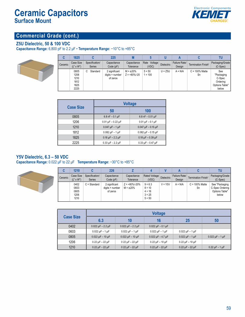
59
Ceramic CapacitorsSurface Mount
Commercial Grade (cont.) Z5U Dielectric, 50 & 100 VDCCapacitance Range: 6,800 pF to 2.2 μF • Temperature Range: −10°C to +85°C
Order ng I ormation
C 1825 C 225 M 5 U A C TU
Ceramic Case Size (L" x W")
Specifi cation/Series
Capacitance Code (pF)
Capacitance Tolerance
Rate Voltage (VDC) Dielectric Failure Rate/
Design Termination Finish1 Packaging/Grade (C-Spec)
080512061210181218252225
C Standard 2 signifi cant digits + number
of zeros
M = ±20%Z = +80%/-20
5 = 501 = 100
U = Z5U A = N/A C = 100% Matte Sn
See"Packaging
C-Spec Ordering
Options Table" below
Case SizeVoltage
50 1000805 6.8 nF – 0.1 µF 6.8 nF – 0.01 µF
1206 0.01 µF – 0.22 µF 0.01 µF – 0.1 µF
1210 0.047 µF – 1 µF 0.047 µF – 0.15 µF
1812 0.082 µF – 1 µF 0.082 µF – 0.15 µF
1825 0.18 µF – 2.2 µF 0.18 µF – 0.39 µF
2225 0.33 µF – 2.2 µF 0.33 µF – 0.47 µF
Y5V Dielectric, 6.3 – 50 VDCCapacitance Range: 0.022 μF to 22 μF Temperature Range: −30°C to +85°C
s
85 rat ng temp re ra ge F e H com liant e rat ce o allowing f
lent so derab
Applic
yp c ion lu e li t perature, ing bypa
Overview
A c (E
ri o d electr c
Ordering nformation
C 1210 C 226 Z 4 V A C TU
Ceramic Case Size (L" x W")
Specifi cation/Series
Capacitance Code (pF)
Capacitance Tolerance
Rated Voltage (VDC) Dielectric Failure Rate/
Design Termination Finish1 Packaging/Grade (C-Spec)
04020603080512061210
C = Standard 2 signifi cant digits + number
of zeros
Z = +80%/-20%M = ±20%
9 = 6.38 = 104 = 163 = 255 = 50
V = Y5V A = N/A C = 100% Matte Sn
See "Packaging C-Spec Ordering Options Table"
below
Case SizeVoltage
6.3 10 16 25 500402 0.022 µF – 2.2 µF 0.022 µF – 2 2 µF 0.022 µF – 0.1 µF
0603 0.022 µF – 1 µF 0.022 µF – 1 µF 0.022 µF – 1 µF 0.022 µF – 1 µF
0805 0.022 µF – 10 µF 0.022 µF – 10 µF 0.022 µF – 4.7 µF 0.022 µF – 1 µF 0.022 µF – 1 µF
1206 0.22 µF – 22 µF 0 22 µF – 22 µF 0.22 µF – 10 µF 0.22 µF – 10 µF
1210 0.22 µF – 22 µF 0 22 µF – 22 µF 0.22 µF – 22 µF 0.22 µF – 22 µF 0.22 µF – 1 µF
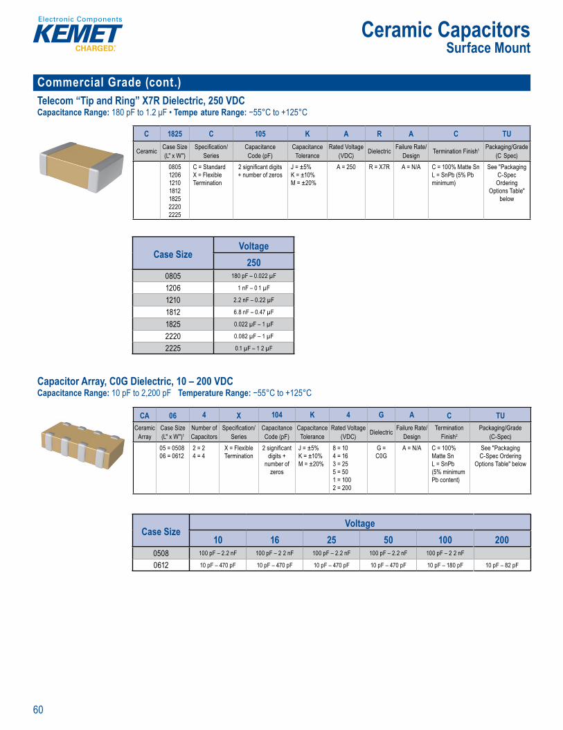
60
Ceramic CapacitorsSurface Mount
Commercial Grade (cont.)Telecom “Tip and Ring” X7R Dielectric, 250 VDCCapacitance Range: 180 pF to 1.2 μF • Tempe ature Range: −55°C to +125°C
• exible term n
Or er n Information
C 1825 C 105 K A R A C TU
Ceramic Case Size (L" x W")
Specifi cation/Series
Capacitance Code (pF)
Capacitance Tolerance
Rated Voltage (VDC) Dielectric Failure Rate/
Design Termination Finish1 Packaging/Grade (C Spec)
0805120612101812182522202225
C = StandardX = Flexible Termination
2 signifi cant digits + number of zeros
J = ±5%K = ±10%M = ±20%
A = 250 R = X7R A = N/A C = 100% Matte SnL = SnPb (5% Pb minimum)
See "Packaging C-Spec Ordering
Options Table" below
Case SizeVoltage
2500805 180 pF – 0.022 µF
1206 1 nF – 0 1 µF
1210 2.2 nF – 0.22 µF
1812 6.8 nF – 0.47 µF
1825 0.022 µF – 1 µF
2220 0.082 µF – 1 µF
2225 0.1 µF – 1 2 µF
Capacitor Array, C0G Dielectric, 10 – 200 VDCCapacitance Range: 10 pF to 2,200 pF Temperature Range: −55°C to +125°C
Overview
E ET s m Ch a c to Arr in C G i ctri is
nt d int m c st l y promot reduced p ent costs a creased
t Thi is eved b tively pla device wo o r iscrete d c s. Use of cap to arra
o c which tes i t ncr a o m r
he vent
manc . his t eveloped ode o
tech r n r of
f the mit g t ng fl ex w IR o r
d a 12 xi
n o n st C0G exhib t nge in capa t c re ct to t me
nd vo a neg ance wit eferen b e em era e Capacitance c nge is limited C
mandin
O dering nformation
CA 06 4 X 10⁴ K 4 G A C TUCeramic
ArrayCase Size (L" x W")1
Number of Capacitors
Specifi cation/Series
CapacitanceCode (pF)
CapacitanceTolerance
Rated Voltage (VDC) Dielectric Failure Rate/
DesignTermination
Finish2Packaging/Grade
(C-Spec)05 = 050806 = 0612
2 = 24 = 4
X = Flexible Termination
2 signifi cant digits +
number of zeros
J = ±5%K = ±10%M = ±20%
8 = 104 = 163 = 255 = 501 = 1002 = 200
G = C0G
A = N/A C = 100% Matte SnL = SnPb (5% minimum Pb content)
See "Packaging C-Spec Ordering
Options Table" below
Case SizeVoltage
10 16 25 50 100 2000508 100 pF – 2.2 nF 100 pF – 2 2 nF 100 pF – 2.2 nF 100 pF – 2.2 nF 100 pF – 2 2 nF
0612 10 pF – 470 pF 10 pF – 470 pF 10 pF – 470 pF 10 pF – 470 pF 10 pF – 180 pF 10 pF – 82 pF
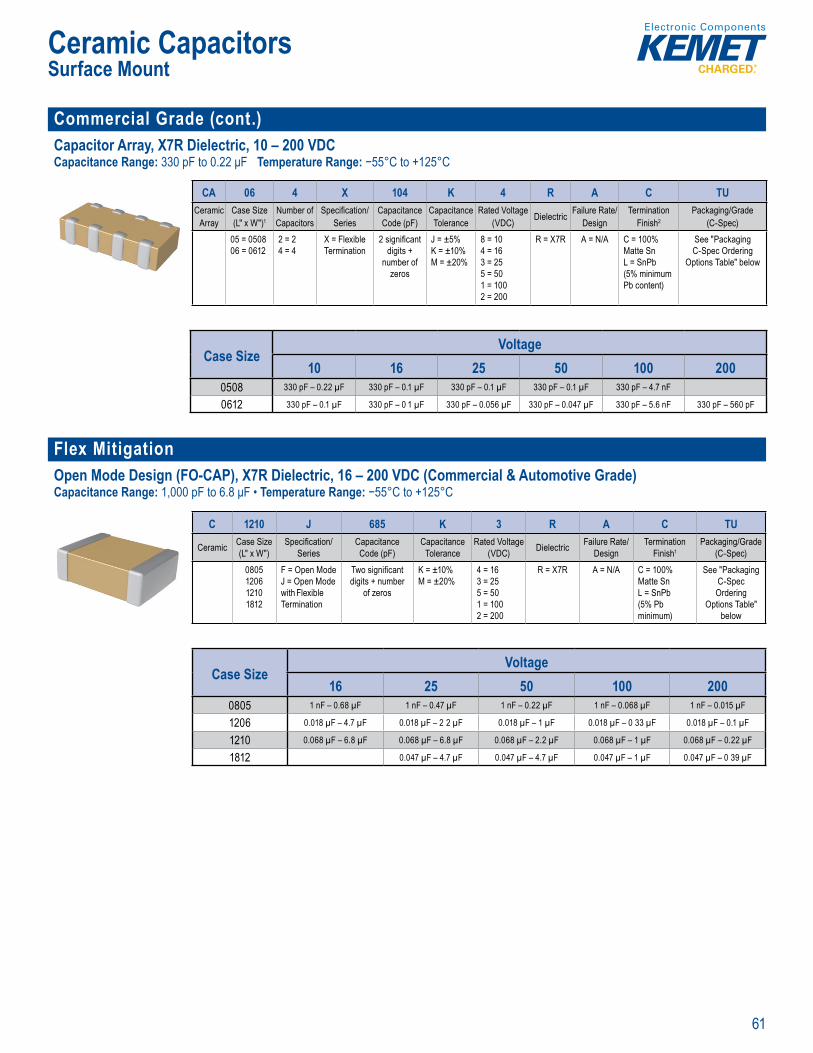
61
Ceramic CapacitorsSurface Mount
Commercial Grade (cont.) Capacitor Array, X7R Dielectric, 10 – 200 VDCCapacitance Range: 330 pF to 0.22 μF Temperature Range: −55°C to +125°C
g ody w ich can r sult in w I
Ordering nformation
CA 06 4 X 10⁴ K 4 R A C TUCeramic
ArrayCase Size (L" x W")1
Number of Capacitors
Specifi cation/Series
CapacitanceCode (pF)
CapacitanceTolerance
Rated Voltage (VDC) Dielectric Failure Rate/
DesignTermination
Finish2Packaging/Grade
(C-Spec)05 = 050806 = 0612
2 = 24 = 4
X = Flexible Termination
2 signifi cant digits +
number of zeros
J = ±5%K = ±10%M = ±20%
8 = 104 = 163 = 255 = 501 = 1002 = 200
R = X7R A = N/A C = 100% Matte SnL = SnPb (5% minimum Pb content)
See "Packaging C-Spec Ordering
Options Table" below
Case SizeVoltage
10 16 25 50 100 2000508 330 pF – 0.22 µF 330 pF – 0.1 µF 330 pF – 0.1 µF 330 pF – 0.1 µF 330 pF – 4.7 nF
0612 330 pF – 0.1 µF 330 pF – 0 1 µF 330 pF – 0.056 µF 330 pF – 0.047 µF 330 pF – 5.6 nF 330 pF – 560 pF
Flex Mitigation Open Mode Design (FO-CAP), X7R Dielectric, 16 – 200 VDC (Commercial & Automotive Grade)Capacitance Range: 1,000 pF to 6.8 μF • Temperature Range: −55°C to +125°C
KEMET’s C r mi pe
f i e. e O e
cit o will not ypic y pr p gate across t e devic s tive are . S c there i not e a y c rre t
er ca t er c a
t O n o acitor a igned f
mperatu and itors
d e stres
i ava ET's y
o t e t
g ci o atu
Order ng I ormation
C 1210 J 685 K 3 R A C TU
Ceramic Case Size (L" x W")
Specifi cation/Series
Capacitance Code (pF)
Capacitance Tolerance
Rated Voltage (VDC) Dielectric Failure Rate/
DesignTermination
Finish1Packaging/Grade
(C-Spec)0805120612101812
F = Open ModeJ = Open Mode with Flexible Termination
Two signifi cant digits + number
of zeros
K = ±10%M = ±20%
4 = 163 = 255 = 501 = 1002 = 200
R = X7R A = N/A C = 100% Matte SnL = SnPb (5% Pb minimum)
See "Packaging C-Spec Ordering
Options Table" below
Case SizeVoltage
16 25 50 100 2000805 1 nF – 0.68 µF 1 nF – 0.47 µF 1 nF – 0.22 µF 1 nF – 0.068 µF 1 nF – 0.015 µF
1206 0.018 µF – 4.7 µF 0.018 µF – 2 2 µF 0.018 µF – 1 µF 0.018 µF – 0 33 µF 0.018 µF – 0.1 µF
1210 0.068 µF – 6.8 µF 0.068 µF – 6.8 µF 0.068 µF – 2.2 µF 0.068 µF – 1 µF 0.068 µF – 0.22 µF
1812 0.047 µF – 4.7 µF 0.047 µF – 4.7 µF 0.047 µF – 1 µF 0.047 µF – 0 39 µF
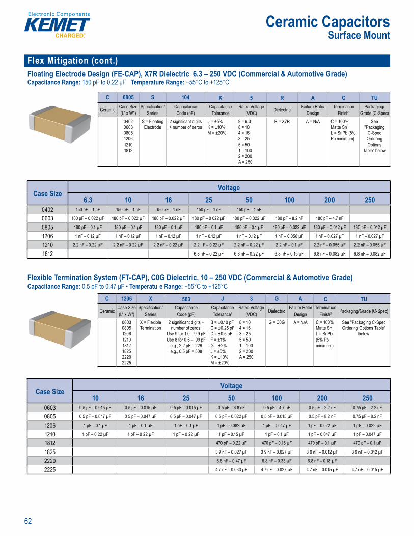
62
Ceramic CapacitorsSurface Mount
Flex Mitigation (cont.)Floating Electrode Design (FE-CAP), X7R Dielectric 6.3 – 250 VDC (Commercial & Automotive Grade)Capacitance Range: 150 pF to 0.22 μF Temperature Range: −55°C to +125°C
Ordering nformation
C 0805 S 104 K 5 R A C TU
Ceramic Case Size (L" x W")
Specifi cation/Series
Capacitance Code (pF)
Capacitance Tolerance
Rated Voltage (VDC) Dielectric Failure Rate/
DesignTermination
Finish1Packaging/
Grade (C-Spec)040206030805120612101812
S = Floating Electrode
2 signifi cant digits + number of zeros
J = ±5%K = ±10%M = ±20%
9 = 6.38 = 104 = 163 = 255 = 501 = 1002 = 200A = 250
R = X7R A = N/A C = 100% Matte SnL = SnPb (5% Pb minimum)
See "Packaging
C-Spec Ordering Options
Table" below
Case SizeVoltage
6.3 10 16 25 50 100 200 2500402 150 pF – 1 nF 150 pF – 1 nF 150 pF – 1 nF 150 pF – 1 nF 150 pF – 1 nF
0603 180 pF – 0.022 µF 180 pF – 0.022 µF 180 pF – 0.022 µF 180 pF – 0 022 µF 180 pF – 0.022 µF 180 pF – 8.2 nF 180 pF – 4.7 nF
0805 180 pF – 0.1 µF 180 pF – 0.1 µF 180 pF – 0.1 µF 180 pF – 0.1 µF 180 pF – 0.1 µF 180 pF – 0.022 µF 180 pF – 0.012 µF 180 pF – 0.012 µF
1206 1 nF – 0.12 µF 1 nF – 0 12 µF 1 nF – 0.12 µF 1 nF – 0.12 µF 1 nF – 0.12 µF 1 nF – 0.056 µF 1 nF – 0.027 µF 1 nF – 0.027 µF
1210 2.2 nF – 0.22 µF 2 2 nF – 0 22 µF 2 2 nF – 0 22 µF 2 2 F – 0 22 µF 2.2 nF – 0.22 µF 2 2 nF – 0.1 µF 2.2 nF – 0.056 µF 2.2 nF – 0.056 µF
1812 6.8 nF – 0 22 µF 6.8 nF – 0.22 µF 6.8 nF – 0.15 µF 6.8 nF – 0.082 µF 6.8 nF – 0.082 µF
Flexible Termination System (FT-CAP), C0G Dielectric, 10 – 250 VDC (Commercial & Automotive Grade)Capacitance Range: 0.5 pF to 0.47 μF • Temperatu e Range: −55°C to +125°C
Over i
KEMET’ Fl ible Te mi ti n (FT C P) til yer mic pac tor n die ectr c ncorporates a qu fl xib
mi materi nd pox tw metal and ic el barrier l s of KEME ndard
rmin ti sys em der to pliability intaining gt , e bi ity a e ectrical pe fo m ce is
was d ped in or to address the p m fai ur s– esu of
s le y li
uperior nc ter ms.
t C o t n lect th Flex ble t on ( -C and M T owe So on (K S) p od lines y provid a co e por l of it g t so u
e st e ec d to ac mo at a apa ce e u rement e e fl ex r bust
o ex bend cap t
d e hi it o ch n n ca cit nce th re t
I additio Grade Auto e Grade d s are availa h m et t andi g ve El nics Counci s AE u i cati e e
i l ri
Ord ri g I formationC 1206 X 563 J 3 G A C TU
Ceramic Case Size (L" x W")
Specifi cation/Series
CapacitanceCode (pF)
Capacitance Tolerance1
Rated Voltage (VDC) Dielectric Failure Rate/
DesignTermination
Finish2 Packaging/Grade (C-Spec)
06030805120612101812182522202225
X = Flexible Termination
2 signifi cant digits +number of zeros.
Use 9 for 1.0 – 9.9 pFUse 8 for 0.5 – 99 pF
e.g., 2.2 pF = 229e.g., 0.5 pF = 508
B = ±0.10 pFC = ±0.25 pFD = ±0.5 pFF = ±1%G = ±2%J = ±5%K = ±10%M = ±20%
8 = 104 = 163 = 255 = 501 = 1002 = 200A = 250
G = C0G A = N/A C = 100% Matte Sn L = SnPb (5% Pb minimum)
See "Packaging C-Spec Ordering Options Table"
below
Case SizeVoltage
10 16 25 50 100 200 2500603 0 5 pF – 0.015 µF 0 5 pF – 0.015 µF 0 5 pF – 0.015 µF 0.5 pF – 6.8 nF 0.5 pF – 4.7 nF 0.5 pF – 2.2 nF 0.75 pF – 2 2 nF
0805 0 5 pF – 0.047 µF 0 5 pF – 0.047 µF 0 5 pF – 0.047 µF 0.5 pF – 0.022 µF 0 5 pF – 0.015 µF 0.5 pF – 8.2 nF 0.75 pF – 8.2 nF
1206 1 pF – 0.1 µF 1 pF – 0.1 µF 1 pF – 0.1 µF 1 pF – 0.082 µF 1 pF – 0.047 µF 1 pF – 0.022 µF 1 pF – 0.022 µF
1210 1 pF – 0 22 µF 1 pF – 0 22 µF 1 pF – 0 22 µF 1 pF – 0.15 µF 1 pF – 0.1 µF 1 pF – 0.047 µF 1 pF – 0.047 µF
1812 470 pF – 0.22 µF 470 pF – 0.15 µF 470 pF – 0.1 µF 470 pF – 0.1 µF
1825 3 9 nF – 0.027 µF 3 9 nF – 0.027 µF 3 9 nF – 0.012 µF 3 9 nF – 0.012 µF
2220 6.8 nF – 0.47 µF 6.8 nF – 0.33 µF 6.8 nF – 0.18 µF
2225 4.7 nF – 0.033 µF 4.7 nF – 0.027 µF 4.7 nF – 0.015 µF 4.7 nF – 0.015 µF
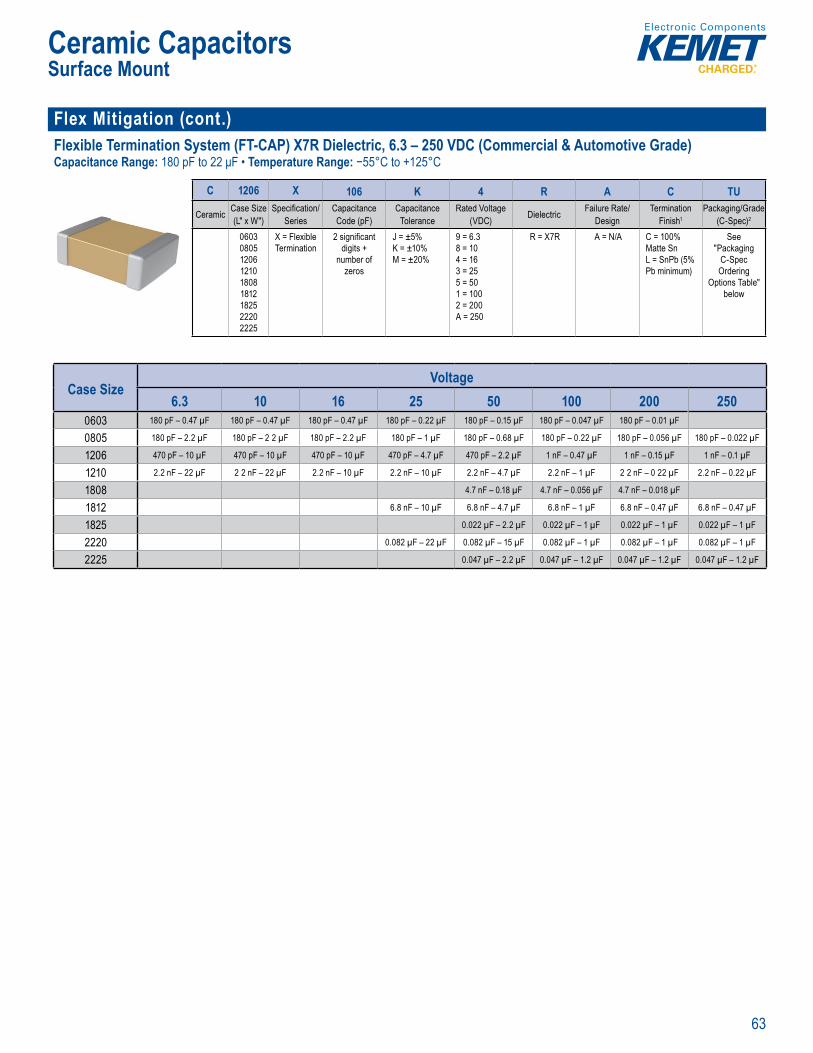
63
Ceramic CapacitorsSurface Mount
Flex Mitigation (cont.)Flexible Termination System (FT-CAP) X7R Dielectric, 6.3 – 250 VDC (Commercial & Automotive Grade)Capacitance Range: 180 pF to 22 μF • Temperature Range: −55°C to +125°C
complements E E s CAP) Flo t ng El c rod
Ordering nformat on
C 1206 X 106 K 4 R A C TU
Ceramic Case Size (L" x W")
Specifi cation/Series
Capacitance Code (pF)
Capacitance Tolerance
Rated Voltage (VDC) Dielectric Failure Rate/
DesignTermination
Finish1Packaging/Grade
(C-Spec)2
060308051206121018081812182522202225
X = Flexible Termination
2 signifi cant digits +
number of zeros
J = ±5%K = ±10%M = ±20%
9 = 6.38 = 104 = 163 = 255 = 501 = 1002 = 200A = 250
R = X7R A = N/A C = 100% Matte SnL = SnPb (5% Pb minimum)
See "Packaging
C-Spec Ordering
Options Table" below
Case SizeVoltage
6.3 10 16 25 50 100 200 2500603 180 pF – 0.47 µF 180 pF – 0.47 µF 180 pF – 0.47 µF 180 pF – 0.22 µF 180 pF – 0.15 µF 180 pF – 0.047 µF 180 pF – 0.01 µF
0805 180 pF – 2.2 µF 180 pF – 2 2 µF 180 pF – 2.2 µF 180 pF – 1 µF 180 pF – 0.68 µF 180 pF – 0.22 µF 180 pF – 0.056 µF 180 pF – 0.022 µF
1206 470 pF – 10 µF 470 pF – 10 µF 470 pF – 10 µF 470 pF – 4.7 µF 470 pF – 2.2 µF 1 nF – 0.47 µF 1 nF – 0.15 µF 1 nF – 0.1 µF
1210 2.2 nF – 22 µF 2 2 nF – 22 µF 2.2 nF – 10 µF 2.2 nF – 10 µF 2.2 nF – 4.7 µF 2.2 nF – 1 µF 2 2 nF – 0 22 µF 2.2 nF – 0.22 µF
1808 4.7 nF – 0.18 µF 4.7 nF – 0.056 µF 4.7 nF – 0.018 µF
1812 6.8 nF – 10 µF 6.8 nF – 4.7 µF 6.8 nF – 1 µF 6.8 nF – 0.47 µF 6.8 nF – 0.47 µF
1825 0.022 µF – 2.2 µF 0.022 µF – 1 µF 0.022 µF – 1 µF 0.022 µF – 1 µF
2220 0.082 µF – 22 µF 0.082 µF – 15 µF 0.082 µF – 1 µF 0.082 µF – 1 µF 0.082 µF – 1 µF
2225 0.047 µF – 2.2 µF 0.047 µF – 1.2 µF 0.047 µF – 1.2 µF 0.047 µF – 1.2 µF
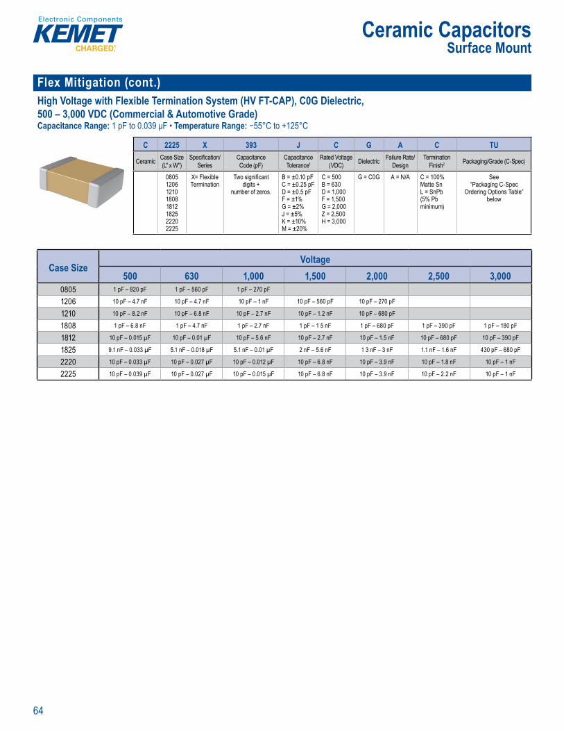
64
Ceramic CapacitorsSurface Mount
Flex Mitigation (cont.) High Voltage with Flexible Termination System (HV FT-CAP), C0G Dielectric, 500 – 3,000 VDC (Commercial & Automotive Grade)Capacitance Range: 1 pF to 0.039 μF • Temperature Range: −55°C to +125°C
Order ng Information
C 2225 X 393 J C G A C TU
Ceramic Case Size (L" x W")
Specifi cation/Series
Capacitance Code (pF)
Capacitance Tolerance1
Rated Voltage (VDC) Dielectric Failure Rate/
DesignTermination
Finish2 Packaging/Grade (C-Spec)
08051206121018081812182522202225
X= Flexible Termination
Two signifi cant digits +
number of zeros.
B = ±0.10 pFC = ±0.25 pFD = ±0.5 pFF = ±1%G = ±2%J = ±5%K = ±10%M = ±20%
C = 500B = 630D = 1,000F = 1,500G = 2,000Z = 2,500H = 3,000
G = C0G A = N/A C = 100% Matte SnL = SnPb (5% Pb minimum)
See“Packaging C-Spec
Ordering Options Table” below
Case SizeVoltage
500 630 1,000 1,500 2,000 2,500 3,0000805 1 pF – 820 pF 1 pF – 560 pF 1 pF – 270 pF
1206 10 pF – 4.7 nF 10 pF – 4.7 nF 10 pF – 1 nF 10 pF – 560 pF 10 pF – 270 pF
1210 10 pF – 8.2 nF 10 pF – 6.8 nF 10 pF – 2.7 nF 10 pF – 1.2 nF 10 pF – 680 pF
1808 1 pF – 6.8 nF 1 pF – 4.7 nF 1 pF – 2.7 nF 1 pF – 1 5 nF 1 pF – 680 pF 1 pF – 390 pF 1 pF – 180 pF
1812 10 pF – 0.015 µF 10 pF – 0.01 µF 10 pF – 5.6 nF 10 pF – 2.7 nF 10 pF – 1.5 nF 10 pF – 680 pF 10 pF – 390 pF
1825 9.1 nF – 0.033 µF 5.1 nF – 0.018 µF 5.1 nF – 0.01 µF 2 nF – 5.6 nF 1 3 nF – 3 nF 1.1 nF – 1.6 nF 430 pF – 680 pF
2220 10 pF – 0.033 µF 10 pF – 0.027 µF 10 pF – 0.012 µF 10 pF – 6.8 nF 10 pF – 3.9 nF 10 pF – 1.8 nF 10 pF – 1 nF
2225 10 pF – 0.039 µF 10 pF – 0.027 µF 10 pF – 0.015 µF 10 pF – 6.8 nF 10 pF – 3.9 nF 10 pF – 2.2 nF 10 pF – 1 nF

65
Ceramic CapacitorsSurface Mount
Flex Mitigation (cont.)High Voltage with Flexible Termination System (HV FT-CAP) X7R Dielectric, 500 – 3,000 VDC (Commercial & Automotive Grade)Capacitance Range: 10 pF to 0.33 μF • Temperature Range: −55°C to +125°C
o s ballasts. Their excep ion
and test d
O der ng nformation
C 1210 X 154 K C R A C TU
Ceramic Case Size (L" x W")
Specifi cation/Series
Capacitance Code (pF)
Capacitance Tolerance
Rated Voltage (VDC) Dielectric Failure Rate/
DesignTermination
Finish1Packaging/Grade
(C-Spec)060308051206121018081812182522202225
X = Flexible Termination
Two signifi cant digits + number
of zeros.
J = ±5%K = ±10%M = ±20%
C = 500 B = 630 D = 1,000 F = 1,500 G = 2,000 Z = 2,500 H = 3,000
R = X7R A = N/A C = 100% Matte SnL = SnPb (5% Pb minimum)
See "Packaging C-Spec Ordering Options Table"
below
Case SizeVoltage
500 630 1,000 1,500 2,000 2,500 3,0000603 1 nF – 3.9 nF 1 nF – 1 5 nF 1 nF
0805 10 pF – 0.022 µF 10 pF – 0.012 µF 10 pF – 5.6 nF
1206 10 pF – 0.068 µF 10 pF – 0.033 µF 10 pF – 0.022 µF 10 pF – 0.01 µF 10 pF – 2.2 nF
1210 10 pF – 0.15 µF 10 pF – 0.1 µF 10 pF – 0.068 µF 10 pF – 0.039 µF 10 pF – 6.8 nF
1808 10 pF – 0.15 µF 10 pF – 0.1 µF 10 pF – 0.068 µF 10 pF – 0.015 µF 10 pF – 4.7 nF 10 pF – 2.2 nF 10 pF – 1 nF
1812 51 pF – 0.33 µF 51 pF – 0.15 µF 51 pF – 0.1 µF 51 pF – 0.033 µF 51 pF – 0.01 µF 51 pF – 4.7 nF 51 pF – 1.2 nF
1825 470 pF – 0.39 µF 470 pF – 0.27 µF 470 pF – 0.1 µF 470 pF – 0.068 µF 470 pF – 0.015 µF 470 pF – 0.01 µF 470 pF – 3 3 nF
2220 470 pF – 0.47 µF 470 pF – 0.33 µF 470 pF – 0.12 µF 470 pF – 0.082 µF 470 pF – 0.022 µF 470 pF – 0.015 µF 470 pF – 0.015 µF
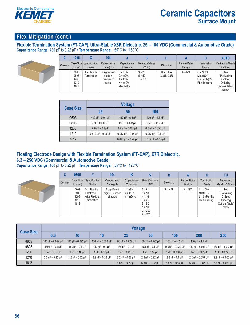
66
Ceramic CapacitorsSurface Mount
Flex Mitigation (cont.)Flexible Termination System (FT-CAP), Ultra-Stable X8R Dielectric, 25 – 100 VDC (Commercial & Automotive Grade)Capacitance Range: 430 pF to 0.22 μF • Temperature Range: −55°C to +150°C
O dering fo matio
C 1206 X 104 J 3 H A C AUTO
Ceramic Case Size (L" x W")
Specifi cation/Series
Capacitance Code (pF)
Capacitance Tolerance
Reated Voltage (VDC) Dielectric Failure Rate/
DesignTermination
Finish1Packaging/Grade
(C-Spec)06030805120612101812
X = Flexible Termination
2 signifi cant digits +
number of zeros
F = ±1%G = ±2%J = ±5%K = ±10%M = ±20%
3 = 255 = 501 = 100
H = Ultra-Stable X8R
A = N/A C = 100% Matte SnL = SnPb (5% Pb minimum)
See "Packaging
C-Spec Ordering
Options Table" below
Case SizeVoltage
25 50 1000603 430 pF – 0.01 µF 430 pF – 6.8 nF 430 pF – 4.7 nF
0805 2 nF – 0.033 µF 2 nF – 0.022 µF 2 nF – 0.015 µF
1206 6 8 nF – 0 1 µF 6.8 nF – 0.082 µF 6.8 nF – 0.056 µF
1210 0.012 µF 0.18 µF 0 012 µF – 0 15 µF 0.012 µF – 0.1 µF
1812 0.015 µF – 0.22 µF 0.015 µF – 0.15 µF
Floating Electrode Design with Flexible Termination System (FF-CAP), X7R Dielectric, 6.3 – 250 VDC (Commercial & Automotive Grade)Capacitance Range: 180 pF to 0.22 μF Temperature Range: −55°C to +125°C
nat o System i l A t t G ad )
loa n le o xi l mi ti c t (FF AP c m i s wo exist n KEMET hn l g es Fl ati g
le tr de a i le Terminat on The fl atin e e r de t z c
o olit c str ct r This ni co fi gur ti s lts in
p ile a ng for a a n co i i ech
rac ermina io m one s il he ba e and
s f st
a ,
ty i ll the h ar stres and
i l d enta ling iti c m n tion o
o tec ovide the u tim ev l of pro ectio low e FF CA
uct ines b pr g t m te a ig ti l t mi r ng c p cit c v lu s These d v ce e hib t a
i i 15 55°C + 25 C
n to om omot ve ev ces g Automoti c ron c
reme ts
Ordering nformation
C 0805 Y 104 K 5 R A C TU
Ceramic Case Size (L" x W")
Specifi cation/Series
Capacitance Code (pF)
Capacitance Tolerance
Rated Voltage (VDC) Dielectric Failure Rate/
DesignTermination
Finish1Packaging/
Grade (C-Spec)06030805120612101812
Y = Floating Electrode with Flexible Termination
2 signifi cant digits + number
of zeros
J = ±5%K = ±10%M = ±20%
9 = 6 38 = 104 = 163 = 255 = 501 = 1002 = 200A = 250
R = X7R A = N/A C = 100% Matte SnL = SnPb (5% Pb minimum)
See "Packaging
C-Spec Ordering
Options Table" below
Case SizeVoltage
6.3 10 16 25 50 100 200 2500603 180 pF – 0.022 µF 180 pF – 0.022 µF 180 pF – 0.022 µF 180 pF – 0.022 µF 180 pF – 0.022 µF 180 pF – 8.2 nF 180 pF – 4.7 nF
0805 180 pF – 0.1 µF 180 pF – 0.1 µF 180 pF – 0.1 µF 180 pF – 0.1 µF 180 pF – 0.1 µF 180 pF – 0.022 µF 180 pF – 0.012 µF 180 pF – 0.012 µF
1206 1 nF – 0.12 µF 1 nF – 0.12 µF 1 nF – 0.12 µF 1 nF – 0.12 µF 1 nF – 0.12 µF 1 nF – 0.056 µF 1 nF – 0.027 µF 1 nF – 0.027 µF
1210 2.2 nF – 0.22 µF 2 2 nF – 0 22 µF 2.2 nF – 0.22 µF 2 2 nF – 0 22 µF 2.2 nF – 0.22 µF 2 2 nF – 0.1 µF 2.2 nF – 0.056 µF 2.2 nF – 0.056 µF
1812 6.8 nF – 0 22 µF 6.8 nF – 0.22 µF 6.8 nF – 0.15 µF 6.8 nF – 0.082 µF 6.8 nF – 0.082 µF

67
Ceramic CapacitorsSurface Mount
Flex Mitigation (cont.)KPS Series, X7R Dielectric, 10 – 250 VDC (Commercial Grade)Capacitance Range: 0.1 μF to 47 μF • Temperature Range: −55°C to +125°C
Orde ing Information
C 2220 C 106 M 5 R 2 C 7186
Ceramic Case Size (L" x W")
Specifi cation/Series
Capacitance Code (pF)
Capacitance Tolerance1
Rated Voltage (VDC) Dielectric Failure Rate/Design Leadframe
Finish2Packaging/Grade
(C-Spec)
121018122220
C = Standard Two signifi cant digits +
number of zeros
K = ±10%M = ±20%
8 = 104 = 163 = 255 = 501 = 100A = 250
R = X7R 1 = KPS Single Chip Stack2 = KPS Double Chip Stack
C = 100% Matte Sn
See “Packaging C-Spec Ordering
Options Table” below
• Higher capacitance in • Potentia o rd s ace r m
Case SizeVoltage
10 16 25 50 100 2501210-1 0.1 µF – 22 µF 0.1 µF – 10 µF 0.1 µF – 10 µF 0.1 µF – 4.7 µF 0.1 µF – 2 2 µF 0.1 µF
1210-2 0.1 µF – 47 µF 0.1 µF – 22 µF 0.1 µF – 22 µF 0.1 µF – 10 µF 0.1 µF – 4.7 µF 0.1 µF – 0 22 µF
1812-1 0.1 µF – 10 µF 0.1 µF – 10 µF 0.1 µF – 4.7 µF 0.1 µF – 1 µF 0.1 µF – 0.47 µF
1812-2 0.1 µF – 22 µF 0.1 µF – 22 µF 0.1 µF – 10 µF 0.1 µF – 3 3 µF 0.1 µF – 1 µF
2220-1 0.1 µF – 22 µF 0.1 µF – 22 µF 0.1 µF – 10 µF 0.1 µF – 3 3 µF 0.1 µF – 1 µF
2220-2 0.1 µF – 47 µF 0.1 µF – 47 µF 0.1 µF – 22 µF 0.1 µF – 4.7 µF 0.1 µF – 2.2 µF
KPS Series, High Voltage, X7R Dielectric, 500 – 630 VDC (Commercial Grade)Capacitance Range: 0.047 μF to 1 0 μF • Tempe ature Range: −55°C to +125°C
222 o ta e acitan µ up o 1 ilab e c % n ±20
c r
ve t ca ly nto ngle mpact surfa e mou t p kage he a ta h e fr e y at pacit r( h
i t f ri t l stre m t n es
bias vo t g s li A t p stack ff up to do e
red l mo t C e ic
p o x capabi i menta
a ie tions
Con entional include both snu s a d fi lte n ap ic t o i ti rmanc at igh f cies has h g cap ce o
n powe l t
Order ng I ormation
C 2220 C 105 M C R 2 C 7186
Ceramic Case Size (L"x W")
Specifi cation/Series
CapacitanceCode (pF)
CapacitanceTolerance1
Rated Voltage(VDC) Dielectric Failure Rate/
DesignLeadframe
Finish2Packaging/Grade
(C-Spec)2220 C =
Standard2 signifi cant digits +
number of zeros.K = ±10%M = ±20%
C = 500B = 630
R = X7R 1 = KPS Single Chip Stack2 = KPS Double Chip Stack
C = 100% Matte Sn
See “Packaging C-Spec Ordering
Options Table” below
Case SizeVoltage
500 6302220-1 0.047 µF – 0.47 µF 0.047 µF – 0.22 µF
2220-2 0.1 µF – 1 µF 0.1 µF – 0.47 µF
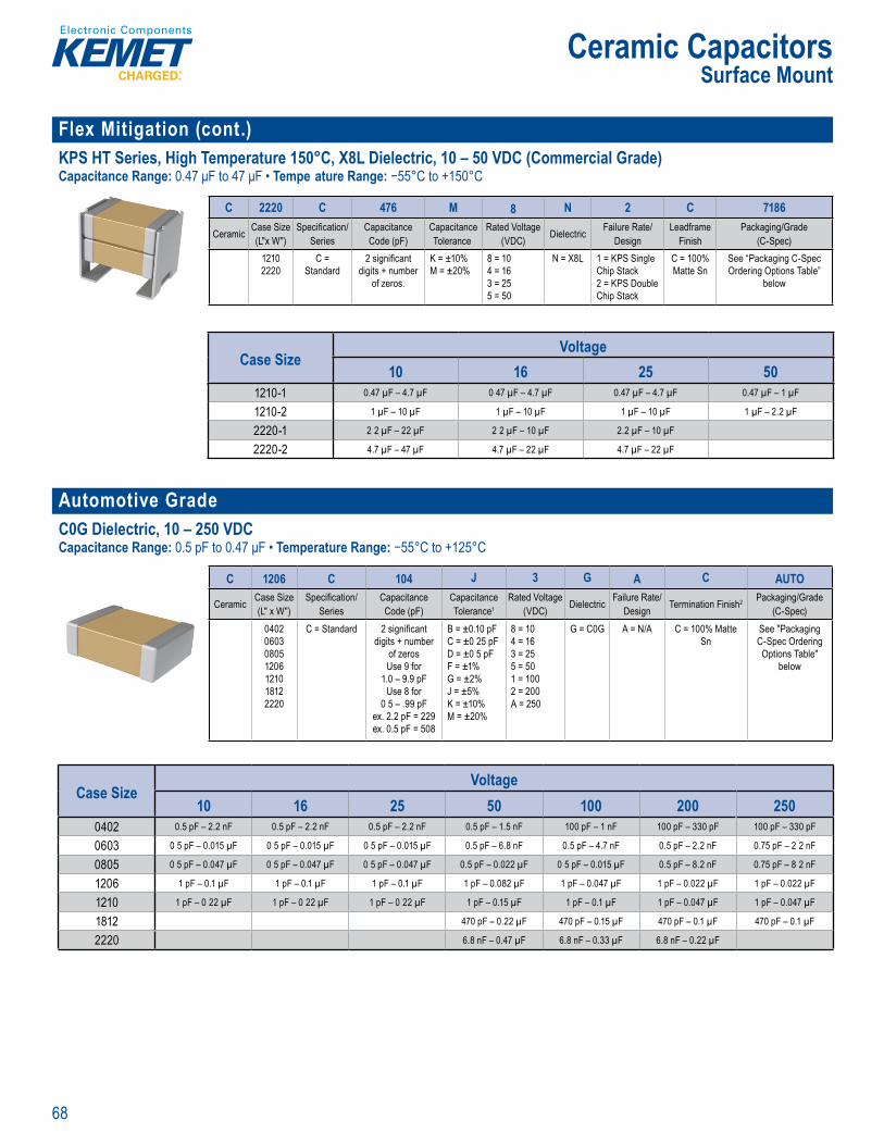
68
Ceramic CapacitorsSurface Mount
Flex Mitigation (cont.)KPS HT Series, High Temperature 150°C, X8L Dielectric, 10 – 50 VDC (Commercial Grade)Capacitance Range: 0.47 μF to 47 μF • Tempe ature Range: −55°C to +150°C
Order ng n orm ti
C 2220 C 476 M 8 N 2 C 7186
Ceramic Case Size (L"x W")
Specifi cation/Series
CapacitanceCode (pF)
CapacitanceTolerance
Rated Voltage (VDC) Dielectric Failure Rate/
DesignLeadframe
FinishPackaging/Grade
(C-Spec)12102220
C = Standard
2 signifi cant digits + number
of zeros.
K = ±10%M = ±20%
8 = 104 = 163 = 255 = 50
N = X8L 1 = KPS Single Chip Stack2 = KPS Double Chip Stack
C = 100% Matte Sn
See “Packaging C-Spec Ordering Options Table”
below
v
Case SizeVoltage
10 16 25 501210-1 0.47 µF – 4.7 µF 0 47 µF – 4.7 µF 0.47 µF – 4.7 µF 0.47 µF – 1 µF
1210-2 1 µF – 10 µF 1 µF – 10 µF 1 µF – 10 µF 1 µF – 2.2 µF
2220-1 2 2 µF – 22 µF 2 2 µF – 10 µF 2.2 µF – 10 µF
2220-2 4.7 µF – 47 µF 4.7 µF – 22 µF 4.7 µF – 22 µF
Automotive GradeC0G Dielectric, 10 – 250 VDCCapacitance Range: 0.5 pF to 0.47 μF • Temperature Range: −55°C to +125°C
C to +125°C o re 2 060 2 0 18 2 nd zes ge ratin V V 1 50 V tance of om 0 pF up le cap s o ± . 0 pF 5 ,
equi in
the vital and robu t nat re of cap citors required r m s on a d af ty c i ica automotive circuits. Stricte testin rotoc
de ucts nit ntial vir
s. KEME automotive ade ser es acitors me t ding A otive nics ou AEC–Q2
req nts
and are su ted for r sonant cir
sts e ap efere
am ture. Capac ce chan mited to ±30 pº 55° 25°C
rd ri g formation
C 1206 C 104 J 3 G A C AUTO
Ceramic Case Size (L" x W")
Specifi cation/Series
Capacitance Code (pF)
Capacitance Tolerance1
Rated Voltage (VDC) Dielectric Failure Rate/
Design Termination Finish2 Packaging/Grade (C-Spec)
0402060308051206121018122220
C = Standard 2 signifi cant digits + number
of zerosUse 9 for
1.0 – 9.9 pFUse 8 for
0 5 – .99 pFex. 2.2 pF = 229ex. 0.5 pF = 508
B = ±0.10 pFC = ±0 25 pFD = ±0 5 pFF = ±1%G = ±2%J = ±5%K = ±10%M = ±20%
8 = 104 = 163 = 255 = 501 = 1002 = 200A = 250
G = C0G A = N/A C = 100% Matte Sn
See "Packaging C-Spec Ordering Options Table"
below
Case SizeVoltage
10 16 25 50 100 200 2500402 0.5 pF – 2.2 nF 0.5 pF – 2.2 nF 0.5 pF – 2.2 nF 0.5 pF – 1.5 nF 100 pF – 1 nF 100 pF – 330 pF 100 pF – 330 pF
0603 0 5 pF – 0.015 µF 0 5 pF – 0.015 µF 0 5 pF – 0.015 µF 0.5 pF – 6.8 nF 0.5 pF – 4.7 nF 0.5 pF – 2.2 nF 0.75 pF – 2 2 nF
0805 0 5 pF – 0.047 µF 0 5 pF – 0.047 µF 0 5 pF – 0.047 µF 0.5 pF – 0.022 µF 0 5 pF – 0.015 µF 0.5 pF – 8.2 nF 0.75 pF – 8 2 nF
1206 1 pF – 0.1 µF 1 pF – 0.1 µF 1 pF – 0.1 µF 1 pF – 0.082 µF 1 pF – 0.047 µF 1 pF – 0.022 µF 1 pF – 0.022 µF
1210 1 pF – 0 22 µF 1 pF – 0 22 µF 1 pF – 0 22 µF 1 pF – 0.15 µF 1 pF – 0.1 µF 1 pF – 0.047 µF 1 pF – 0.047 µF
1812 470 pF – 0.22 µF 470 pF – 0.15 µF 470 pF – 0.1 µF 470 pF – 0.1 µF
2220 6.8 nF – 0.47 µF 6.8 nF – 0.33 µF 6.8 nF – 0.22 µF

69
Ceramic CapacitorsSurface Mount
Automotive Grade (cont.)X7R Dielectric, 6.3 – 250 VDCCapacitance Range: 10 pF to 22 μF Tempe ature Range: −55°C to +125°C
2 0 , nd 250 V• Capacitance of e ng
s
O deri g Information
C 0805 C 225 M 4 R A C AUTO
Ceramic Case Size (L" x W")
Specifi cation/Series
Capacitance Code (pF)
Capacitance Tolerance
Rated Voltage (VDC) Dielectric Failure Rate/
Desig Termination Finish1 Packaging/Grade (C-Spec)
04 2060308051206121018122220
C = Standard Two s gnifi cant digits + number
of zeros.
J = ±5%K = ±10%M = ±20%
9 = 6.3 8 = 10 4 = 16 3 = 25 5 = 50 1 = 100 2 = 200 A = 250
R = X7R A = N/A C 100% Matte Sn
See "Packaging C-Spec Ordering
Options Table" below
Case SizeVoltage
6.3 10 16 25 50 100 200 2500402 10 pF – 0.1 µF 10 pF – 0.1 µF 10 pF – 0.047 µF 10 pF – 0.022 µF
0603 10 pF – 0.47 µF 10 pF – 0.47 µF 10 pF – 0.47 µF 10 pF – 0 22 µF 10 pF – 0.15 µF 10 pF – 0.047 µF 10 pF – 0.01 µF
0805 10 pF – 2.2 µF 10 pF – 2.2 µF 10 pF – 2 2 µF 10 pF – 1 µF 10 pF – 0.68 µF 10 pF – 0 22 µF 10 pF – 0.056 µF 180 pF – 0.022 µF
1206 10 pF – 10 µF 10 pF – 10 µF 10 pF 10 µF 10 pF – 4.7 µF 10 pF – 2.2 µF 10 pF – 0.47 µF 10 pF – 0.15 µF 1 nF – 0.1 µF
1210 10 pF – 22 µF 10 pF – 22 µF 10 pF – 10 µF 10 pF – 10 µF 10 pF – 4.7 µF 10 pF – 1 µF 10 pF – 0.22 µF 2 2 nF – 0 22 µF
1808 330 pF – 0.18 µF 330 pF – 0.056 µF 330 pF – 2.7 nF
1812 470 pF – 10 µF 470 pF – 4.7 µF 470 pF – 1 µF 470 pF – 0.47 µF 6.8 nF – 0.47 µF
1825 0.022 µF – 1 µF 0.022 µF – 1 µF 0.022 µF – 1 µF 0.022 µF – 1 µF
2220 6.8 nF – 22 µF 6.8 nF – 10 µF 6.8 nF – 1 µF 0.082 µF – 1 µF 0.082 µF – 1 µF
Capacitor Array, C0G Dielectric, 10 – 200 VDCCapacitance Range: 10 pF to 2,200 pF Temperature Range: −55°C to +125°C
Ceramic ip Capac to ay in C0G lectric is an a sive ology multiple c or eleme
d in e common olithic struct . Array ment sts re his i
wo o r
m
l orp to p r fl
ce is te g w s ev o es fl d d i o e d th li exi
T on t h ol bits th tran boa st es ri y of he M refore mit g x cr k n
C I
ompo s class fi ca e compensatin an i sonan i i se whe Q a i t o p itan cha acteristics req ired
ce e t to time
to
(
O dering nformation
CA 06 4 X 10⁴ K 4 G A C TUCeramic
ArrayCase Size (L" x W")1
Number of Capacitors
Specifi cation/Series
CapacitanceCode (pF)
CapacitanceTolerance
Rated Voltage (VDC) Dielectric Failure Rate/
DesignTermination
Finish2Packaging/Grade
(C-Spec)05 = 050806 = 0612
2 = 24 = 4
X = Flexible Termination
2 signifi cant digits +
number of zeros
J = ±5%K = ±10%M = ±20%
8 = 104 = 163 = 255 = 501 = 1002 = 200
G = C0G
A = N/A C = 100% Matte SnL = SnPb (5% minimum Pb content)
See "Packaging C-Spec Ordering
Options Table" below
Case SizeVoltage
10 16 25 50 100 2000508 100 pF – 2.2 nF 100 pF – 2 2 nF 100 pF – 2.2 nF 100 pF – 2.2 nF 100 pF – 2 2 nF
0612 10 pF – 470 pF 10 pF – 470 pF 10 pF – 470 pF 10 pF – 470 pF 10 pF – 180 pF 10 pF – 82 pF
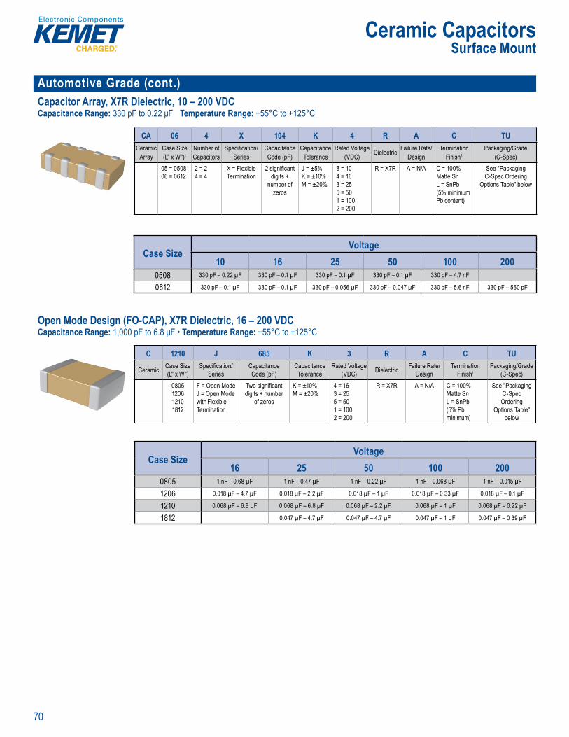
70
Ceramic CapacitorsSurface Mount
Automotive Grade (cont.)Capacitor Array, X7R Dielectric, 10 – 200 VDCCapacitance Range: 330 pF to 0.22 μF Temperature Range: −55°C to +125°C
Ordering nformation
CA 06 4 X 10⁴ K 4 R A C TUCeramic
ArrayCase Size (L" x W")1
Number of Capacitors
Specifi cation/Series
Capac tanceCode (pF)
CapacitanceTolerance
Rated Voltage (VDC) Dielectric Failure Rate/
DesignTermination
Finish2Packaging/Grade
(C-Spec)05 = 050806 = 0612
2 = 24 = 4
X = Flexible Termination
2 signifi cant digits +
number of zeros
J = ±5%K = ±10%M = ±20%
8 = 104 = 163 = 255 = 501 = 1002 = 200
R = X7R A = N/A C = 100% Matte SnL = SnPb (5% minimum Pb content)
See "Packaging C-Spec Ordering
Options Table" below
Case SizeVoltage
10 16 25 50 100 2000508 330 pF – 0.22 µF 330 pF – 0.1 µF 330 pF – 0.1 µF 330 pF – 0.1 µF 330 pF – 4.7 nF
0612 330 pF – 0.1 µF 330 pF – 0.1 µF 330 pF – 0.056 µF 330 pF – 0.047 µF 330 pF – 5.6 nF 330 pF – 560 pF
Open Mode Design (FO-CAP), X7R Dielectric, 16 – 200 VDCCapacitance Range: 1,000 pF to 6.8 μF • Temperature Range: −55°C to +125°C
; w not typic l y th d c c iv ea. S nce t l o it i l ,
s no i d h ti d th ref r litt c f
riven b the dem nd fo a more robust a d reliable ompo nt th O n Mode tor w esig ed f
pp cation wh r r operat n emperat r d T it r ly
pplie
minatio tech
dy t n can e w IR or ho t cir a u es A ou
te m nology oes imi ate the po al
enta a d a l g co d ns d es ro d super r ex ce ove s andard termin ion systems When combin d
se dev ces o e he ul mate t i it i
Order ng I ormation
C 1210 J 685 K 3 R A C TU
Ceramic Case Size (L" x W")
Specifi cation/Series
Capacitance Code (pF)
Capacitance Tolerance
Rated Voltage (VDC) Dielectric Failure Rate/
DesignTermination
Finish1Packaging/Grade
(C-Spec)0805120612101812
F = Open ModeJ = Open Mode with Flexible Termination
Two signifi cant digits + number
of zeros
K = ±10%M = ±20%
4 = 163 = 255 = 501 = 1002 = 200
R = X7R A = N/A C = 100% Matte SnL = SnPb (5% Pb minimum)
See "Packaging C-Spec Ordering
Options Table" below
Case SizeVoltage
16 25 50 100 2000805 1 nF – 0.68 µF 1 nF – 0.47 µF 1 nF – 0.22 µF 1 nF – 0.068 µF 1 nF – 0.015 µF
1206 0.018 µF – 4.7 µF 0.018 µF – 2 2 µF 0.018 µF – 1 µF 0.018 µF – 0 33 µF 0.018 µF – 0.1 µF
1210 0.068 µF – 6.8 µF 0.068 µF – 6.8 µF 0.068 µF – 2.2 µF 0.068 µF – 1 µF 0.068 µF – 0.22 µF
1812 0.047 µF – 4.7 µF 0.047 µF – 4.7 µF 0.047 µF – 1 µF 0.047 µF – 0 39 µF

71
Ceramic CapacitorsSurface Mount
Automotive Grade (cont.)Floating Electrode Design (FE-CAP), X7R Dielectric, 6.3 – 250 VDCCapacitance Range: 150 pF to 0.22 μF Temperature Range: −55°C to +125°C
s
Ordering nformation
C 0805 S 104 K 5 R A C TU
Ceramic Case Size (L" x W")
Specifi cation/Series
Capacitance Code (pF)
Capacitance Tolerance
Rated Voltage (VDC) Dielectric Failure Rate/
DesignTermination
Finish1Packaging/
Grade (C-Spec)040206030805120612101812
S = Floating Electrode
2 signifi cant digits + number of zeros
J = ±5%K = ±10%M = ±20%
9 = 6.38 = 104 = 163 = 255 = 501 = 1002 = 200A = 250
R = X7R A = N/A C = 100% Matte SnL = SnPb (5% Pb minimum)
See "Packaging
C-Spec Ordering Options
Table" below
Case SizeVoltage
6.3 10 16 25 50 100 200 2500402 150 pF – 1 nF 150 pF – 1 nF 150 pF – 1 nF 150 pF – 1 nF 150 pF – 1 nF
0603 180 pF – 0.022 µF 180 pF – 0.022 µF 180 pF – 0.022 µF 180 pF – 0.022 µF 180 pF – 0.022 µF 180 pF – 8.2 nF 180 pF – 4.7 nF
0805 180 pF – 0.1 µF 180 pF – 0.1 µF 180 pF – 0.1 µF 180 pF – 0.1 µF 180 pF – 0.1 µF 180 pF – 0.022 µF 180 pF – 0.012 µF 180 pF – 0.012 µF
1206 1 nF – 0.12 µF 1 nF – 0.12 µF 1 nF – 0.12 µF 1 nF – 0.12 µF 1 nF – 0.12 µF 1 nF – 0.056 µF 1 nF – 0.027 µF 1 nF – 0.027 µF
1210 2.2 nF – 0.22 µF 2 2 nF – 0 22 µF 2 2 nF – 0 22 µF 2 2 nF – 0 22 µF 2.2 nF – 0.22 µF 2 2 nF – 0.1 µF 2.2 nF – 0.056 µF 2.2 nF – 0.056 µF
1812 6.8 nF – 0 22 µF 6.8 nF – 0.22 µF 6.8 nF – 0.15 µF 6.8 nF – 0.082 µF 6.8 nF – 0.082 µF
Flexible Termination System (FT-CAP) X7R Dielectric, 6.3 – 250 VDCCapacitance Range: 180 pF to 22 μF • Temperature Range: −55°C to +125°C
KE E ’s Aut motive Grade Flexible er atio F CAP)
ni xible io t is h
poxy is iliz t r y t a s e e bl s
e m ning term l st engt , sol e b i y and form ed n orde
rim the
a d pr ext
e ental d h cond i s prov d sup x f ce o er da d r in t o st m CA o s e o o r ( E
i T ( i
co t o fo o f fl i i at so ut
v S f o apa
i e age Cap e e e o ie t s te ro 12
W ap citors are gned t n d safet c a t on c i e i hav of p
Su ace ou t ul ila
Fl ibl T
Orderin nformation
C 1206 X 106 K 4 R A C AUTO
Ceramic Case Size (L" x W")
Specifi cation/Series
Capacitance Code (pF)
Capacitance Tolerance
Rated Voltage (VDC) Dielectric Failure Rate/
DesignTermination
Finish1Packaging/Grade
(C-Spec)2
060308051206121018081812182522202225
X = Flexible Termination
2 signifi cant digits +
number of zeros
J = ±5%K = ±10%M = ±20%
9 = 6.38 = 104 = 163 = 255 = 501 = 1002 = 200A = 250
R = X7R A = N/A C = 100% Matte Sn
See "Packaging
C-Spec Ordering
Options Table" below
Case SizeVoltage
6.3 10 16 25 50 100 200 2500603 180 pF – 0.47 µF 180 pF – 0.47 µF 180 pF – 0.47 µF 180 pF – 0.22 µF 180 pF – 0.15 µF 180 pF – 0.047 µF 180 pF – 0.01 µF
0805 180 pF – 2.2 µF 180 pF – 2 2 µF 180 pF – 2.2 µF 180 pF – 1 µF 180 pF – 0.68 µF 180 pF – 0.22 µF 180 pF – 0.056 µF 180 pF – 0.022 µF
1206 1 nF – 10 µF 1 nF – 10 µF 1 nF – 10 µF 1 nF – 4.7 µF 1 nF – 2.2 µF 1 nF – 0.47 µF 1 nF – 0.15 µF 1 nF – 0.1 µF
1210 2.2 nF – 22 µF 2 2 nF – 22 µF 2.2 nF – 10 µF 2.2 nF – 10 µF 2.2 nF – 4.7 µF 2.2 nF – 1 µF 2 2 nF – 0 22 µF 2.2 nF – 0.22 µF
1808 4.7 nF – 0.18 µF 4.7 nF – 0.056 µF 4.7 nF – 0.018 µF
1812 6.8 nF – 10 µF 6.8 nF – 4.7 µF 6.8 nF – 1 µF 6.8 nF – 0.47 µF 6.8 nF – 0.47 µF
1825 0.022 µF – 2.2 µF 0.022 µF – 1 µF 0.022 µF – 1 µF 0.022 µF – 1 µF
2220 0.082 µF – 22 µF 0.082 µF – 10 µF 0.082 µF – 1 µF 0.082 µF – 1 µF 0.082 µF – 1 µF
2225 0.047 µF – 2.2 µF 0.047 µF – 1.2 µF 0.047 µF – 1.2 µF 0.047 µF – 1.2 µF
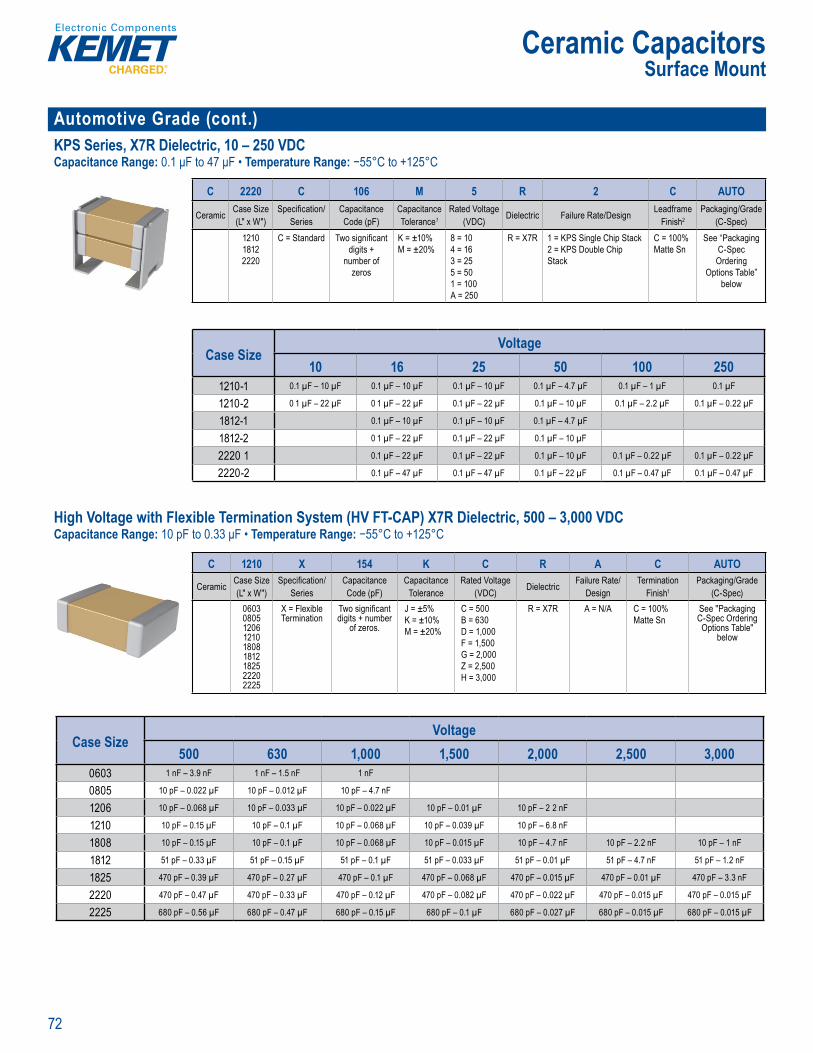
72
Ceramic CapacitorsSurface Mount
Automotive Grade (cont.)KPS Series, X7R Dielectric, 10 – 250 VDCCapacitance Range: 0.1 μF to 47 μF • Temperature Range: −55°C to +125°C
Orde ing Information
C 2220 C 106 M 5 R 2 C AUTO
Ceramic Case Size (L" x W")
Specifi cation/Series
Capacitance Code (pF)
Capacitance Tolerance1
Rated Voltage (VDC) Dielectric Failure Rate/Design Leadframe
Finish2Packaging/Grade
(C-Spec)121018122220
C = Standard Two signifi cant digits +
number of zeros
K = ±10%M = ±20%
8 = 104 = 163 = 255 = 501 = 100A = 250
R = X7R 1 = KPS Single Chip Stack2 = KPS Double Chip Stack
C = 100% Matte Sn
See “Packaging C-Spec Ordering
Options Table” below
Case SizeVoltage
10 16 25 50 100 2501210-1 0.1 µF – 10 µF 0.1 µF – 10 µF 0.1 µF – 10 µF 0.1 µF – 4.7 µF 0.1 µF – 1 µF 0.1 µF
1210-2 0 1 µF – 22 µF 0 1 µF – 22 µF 0.1 µF – 22 µF 0.1 µF – 10 µF 0.1 µF – 2.2 µF 0.1 µF – 0.22 µF
1812-1 0.1 µF – 10 µF 0.1 µF – 10 µF 0.1 µF – 4.7 µF
1812-2 0 1 µF – 22 µF 0.1 µF – 22 µF 0.1 µF – 10 µF
2220 1 0.1 µF – 22 µF 0.1 µF – 22 µF 0.1 µF – 10 µF 0.1 µF – 0.22 µF 0.1 µF – 0.22 µF
2220-2 0.1 µF – 47 µF 0.1 µF – 47 µF 0.1 µF – 22 µF 0.1 µF – 0.47 µF 0.1 µF – 0.47 µF
High Voltage with Flexible Termination System (HV FT-CAP) X7R Dielectric, 500 – 3,000 VDCCapacitance Range: 10 pF to 0.33 μF • Temperature Range: −55°C to +125°C
u w h Fl x b e er mode ML s—fl x crac
ss e si tre d g o r i i
(c a ce v e i try
ase me l an nic l rr er l y f the term t o syst m i y
ri i fo e it ng ex ra e u t cuit failur
ot elim
C f i onv snu
g i
them oic of d nee wor t on to e e c acito
ely u e mot ve(hy i mmunic s ace em c o s
st/d a
ur
Whe er unde d or in-cabin, t e pa it rs designe
i i ui s Stri ter t stin ol a d i ti n criteri blishe ecognit
autom tive lectr
Gr )
O der ng Information
C 1210 X 154 K C R A C AUTO
Ceramic Case Size (L" x W")
Specifi cation/Series
Capacitance Code (pF)
Capacitance Tolerance
Rated Voltage (VDC) Dielectric Failure Rate/
DesignTermination
Finish1Packaging/Grade
(C-Spec)060308051206121018081812182522202225
X = Flexible Termination
Two signifi cant digits + number
of zeros.
J = ±5%K = ±10%M = ±20%
C = 500 B = 630 D = 1,000 F = 1,500 G = 2,000 Z = 2,500 H = 3,000
R = X7R A = N/A C = 100% Matte Sn
See "Packaging C-Spec Ordering Options Table"
below
Case SizeVoltage
500 630 1,000 1,500 2,000 2,500 3,0000603 1 nF – 3.9 nF 1 nF – 1.5 nF 1 nF
0805 10 pF – 0.022 µF 10 pF – 0.012 µF 10 pF – 4.7 nF
1206 10 pF – 0.068 µF 10 pF – 0.033 µF 10 pF – 0.022 µF 10 pF – 0.01 µF 10 pF – 2 2 nF
1210 10 pF – 0.15 µF 10 pF – 0.1 µF 10 pF – 0.068 µF 10 pF – 0.039 µF 10 pF – 6.8 nF
1808 10 pF – 0.15 µF 10 pF – 0.1 µF 10 pF – 0.068 µF 10 pF – 0.015 µF 10 pF – 4.7 nF 10 pF – 2.2 nF 10 pF – 1 nF
1812 51 pF – 0.33 µF 51 pF – 0.15 µF 51 pF – 0.1 µF 51 pF – 0.033 µF 51 pF – 0.01 µF 51 pF – 4.7 nF 51 pF – 1.2 nF
1825 470 pF – 0.39 µF 470 pF – 0.27 µF 470 pF – 0.1 µF 470 pF – 0.068 µF 470 pF – 0.015 µF 470 pF – 0.01 µF 470 pF – 3.3 nF
2220 470 pF – 0.47 µF 470 pF – 0.33 µF 470 pF – 0.12 µF 470 pF – 0.082 µF 470 pF – 0.022 µF 470 pF – 0.015 µF 470 pF – 0.015 µF
2225 680 pF – 0.56 µF 680 pF – 0.47 µF 680 pF – 0.15 µF 680 pF – 0.1 µF 680 pF – 0.027 µF 680 pF – 0.015 µF 680 pF – 0.015 µF

73
Ceramic CapacitorsSurface Mount
Automotive Grade (cont.)KPS Series, High Voltage, X7R Dielectric, 500 – 630 VDCCapacitance Range: 0.047 μF to 1 μF • Temperature Range: −55°C to +125°C
eli l and r ust t
• EIA 2220 case si e p
• otent b a
Orde ng Information
C 2220 C 105 M C R 2 C 7186
Ceramic Case Size (L"x W")
Specifi cation/Series
CapacitanceCode (pF)
CapacitanceTolerance1
Rated Voltage(VDC) Dielectric Failure Rate/
DesignLeadframe
Finish2Packaging/Grade
(C-Spec)2220 C =
Standard2 signifi cant digits +
number of zeros.K = ±10%M = ±20%
C = 500B = 630
R = X7R 1 = KPS Single Chip Stack2 = KPS Double Chip Stack
C = 100% Matte Sn
See “Packaging C-Spec Ordering
Options Table” below
Case SizeVoltage
500 6302220-1 0.047 µF – 0.47 µF 0.047 µF – 0.22 µF
2220-2 0.1 µF – 1 µF 0.1 µF – 0.47 µF
KPS HT Series, High Temperature 150°C, X8L Dielectric, 10 – 50 VDCCapacitance Range: 0.47 μF to 47 μF • Temperature Range: −55°C to +150°C
tac nto a sing e compa t su
w en a bias vo e the apa t i e sam or sm l er de
when om re to t ition l s rf m t M C Pr vi g o 10 mm of bo rd fl ex c bil y KP er
Order ng Information
C 2220 C 476 M 8 N 2 C 7186
Ceramic Case Size (L"x W")
Specifi cation/Series
CapacitanceCode (pF)
CapacitanceTolerance1
Rated Voltage (VDC) Dielectric Failure Rate/
DesignLeadframe
FinishPackaging/Grade
(C-Spec)12102220
C = Standard
2 signifi cant digits + number
of zeros.
K = ±10%M = ±20%
8 = 104 = 163 = 255 = 50
N = X8L 1 = KPS Single Chip Stack2 = KPS Double Chip Stack
C = 100% Matte Sn
See “Packaging C-Spec Ordering Options Table”
below
47 μ able ca acita int l boa d ed o e m l an mec
Case SizeVoltage
10 16 25 501210-1 0.47 µF – 4.7 µF 0.47 µF – 4.7 µF 0.47 µF – 4.7 µF 0.47 µF – 1 µF
1210-2 1 µF – 10 µF 1 µF – 10 µF 1 µF – 10 µF 1 µF – 2.2 µF
2220-1 2.2 µF – 22 µF 2 2 µF – 10 µF 2.2 µF – 10 µF
2220-2 4.7 µF – 47 µF 4.7 µF – 22 µF 4.7 µF – 22 µF

74
Ceramic CapacitorsSurface Mount
Automotive Grade (cont.)Flexible Termination System (FT-CAP), C0G Dielectric, 10 – 250 VDCCapacitance Range: 0.5 pF to 0.47 μF • Temperatu e Range: −55°C to +125°C
Ord ri g I formationC 1206 X 563 J 3 G A C TU
Ceramic Case Size (L" x W")
Specifi cation/Series
CapacitanceCode (pF)
Capacitance Tolerance1
Rated Voltage (VDC) Dielectric Failure Rate/
DesignTermination
Finish2 Packaging/Grade (C-Spec)
06030805120612101812182522202225
X = Flexible Termination
2 signifi cant digits +number of zeros.
Use 9 for 1.0 – 9 9 pFUse 8 for 0.5 – 99 pF
e.g., 2.2 pF = 229e.g., 0.5 pF = 508
B = ±0.10 pFC = ±0.25 pFD = ±0 5 pFF = ±1%G = ±2%J = ±5%K = ±10%M = ±20%
8 = 104 = 163 = 255 = 501 = 1002 = 200A = 250
G = C0G A = N/A C = 100% Matte Sn L = SnPb (5% Pb minimum)
See "Packaging C-Spec Ordering Options Table"
below
Case SizeVoltage
10 16 25 50 100 200 2500603 0.5 pF – 0 015 µF 0.5 pF – 0.015 µF 0 5 pF – 0 015 µF 0 5 pF – 6.8 nF 0.5 pF – 4.7 nF 0.5 pF – 2.2 nF 0.75 pF – 2.2 nF
0805 0 5 pF – 0.047 µF 0 5 pF – 0.047 µF 0 5 pF – 0.047 µF 0.5 pF – 0.022 µF 0 5 pF – 0.015 µF 0.5 pF – 8.2 nF 0.75 pF – 8.2 nF
1206 1 pF – 0.1 µF 1 pF – 0.1 µF 1 pF – 0.1 µF 1 pF – 0.082 µF 1 pF – 0.047 µF 1 pF – 0.022 µF 1 pF – 0.022 µF
1210 1 pF – 0.22 µF 1 pF – 0 22 µF 1 pF – 0 22 µF 1 pF – 0.15 µF 1 pF – 0.1 µF 1 pF – 0.047 µF 1 pF – 0.047 µF
1812 470 pF – 0 22 µF 470 pF – 0.15 µF 470 pF – 0.1 µF 470 pF – 0.1 µF
1825 3 9 nF – 0.027 µF 3.9 nF – 0.027 µF 3 9 nF – 0.012 µF 3 9 nF – 0.012 µF
2220 6.8 nF – 0.47 µF 6.8 nF – 0.33 µF 6.8 nF – 0.18 µF
2225 4.7 nF – 0.033 µF 4.7 nF – 0.027 µF 4.7 nF – 0.015 µF 4.7 nF – 0.015 µF
Flexible Termination System (FT-CAP), Ultra-Stable X8R Dielectric, 25 – 100 VDCCapacitance Range: 430 pF to 0.22 μF • Temperature Range: −55°C to +150°C
Overview
KE ET s Fl le T mi ation (FT CAP) M lt a r ramic a t r in r St b e X8R dielectri r o tes n
i minat e ate s
tilized t en a e i l ers
i e m aining term l streng h, sol bi i y an erfor hnology was de el ed in o de
h ode f M fl c s ic ces ve te sile s ea
oduc cy ling min f board
ol t f gat e v ro a n nd n t ons it d es s er or fl ex pe a ce over st n rm n tion syste -CA om KEME s , Floa ng E (FE
CA Ele t ode ble e i at A ),
e m e m pa p
ta l R dielect f m t erature capabil ty s
D bit no ch e n capacita c with re in mal c pacita
i r t r e hat
Q req
Stable X8R
O deri g f t
C 1206 X 104 J 3 H A C AUTO
Ceramic Case Size (L" x W")
Specifi cation/Series
Capacitance Code (pF)
Capacitance Tolerance
Reated Voltage (VDC) Dielectric Failure Rate/
DesignTermination
Finish1Packaging/Grade
(C-Spec)06030805120612101812
X = Flexible Termination
2 signifi cant digits +
number of zeros.
F = ±1%G = ±2%J = ±5%K = ±10%M = ±20%
3 = 255 = 501 = 100
H = Ultra-Stable X8R
A = N/A C = 100% Matte SnL = SnPb (5% Pb minimum)
See "Packaging
C-Spec Ordering
Options Table" below
Case SizeVoltage
25 50 1000603 430 pF – 0.01 µF 430 pF – 6.8 nF 430 pF – 4.7 nF
0805 2 nF – 0.033 µF 2 nF – 0.022 µF 2 nF – 0.015 µF
1206 6.8 nF – 0.1 µF 6.8 nF – 0.082 µF 6.8 nF – 0.056 µF
1210 0.012 µF – 0.18 µF 0.012 µF – 0.15 µF 0.012 µF – 0.1 µF
1812 0.015 µF – 0.22 µF 0.015 µF – 0.15 µF
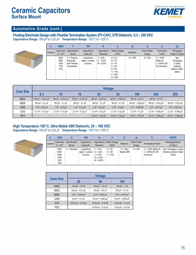
75
Ceramic CapacitorsSurface Mount
Automotive Grade (cont.)Floating Electrode Design with Flexible Termination System (FF-CAP), X7R Dielectric, 6.3 – 250 VDCCapacitance Range: 180 pF to 0.22 μF Temperature Range: −55°C to +125°C
l
environmen al and/ r ha th
Ord ing nforma ion
C 0805 Y 104 K 5 R A C TU
Ceramic Case Size (L" x W")
Specifi cation/Series
Capacitance Code (pF)
Capacitance Tolerance
Rated Voltage (VDC) Dielectric Failure Rate/
DesignTermination
Finish1Packaging/
Grade (C-Spec)06030805120612101812
Y = Floating Electrode with Flexible Termination
2 signifi cant digits + number
of zeros
J = ±5%K ±10%M = ±20%
9 = 6 38 = 104 = 163 = 255 = 501 = 1002 = 200A = 250
R = X7R A = N/A C = 100% Matte SnL = SnPb (5% Pb minimum)
See "Packaging
C-Spec Ordering
Options Table" below
Case SizeVoltage
6.3 10 16 25 50 100 200 2500603 180 pF – 0.022 µF 180 pF – 0.022 µF 180 pF – 0.022 µF 180 pF – 0.022 µF 180 pF – 0.022 µF 180 pF – 8.2 nF 180 pF – 4.7 nF
0805 180 pF – 0.1 µF 180 pF – 0.1 µF 180 pF – 0.1 µF 180 pF – 0.1 µF 180 pF – 0.1 µF 180 pF – 0.022 µF 180 pF – 0.012 µF 180 pF – 0.012 µF
1206 1 nF – 0.12 µF 1 nF – 0.12 µF 1 nF – 0.12 µF 1 nF – 0.12 µF 1 nF – 0.12 µF 1 nF – 0.056 µF 1 nF – 0.027 µF 1 nF – 0.027 µF
1210 2.2 nF – 0.22 µF 2 2 nF – 0 22 µF 2.2 nF – 0.22 µF 2 2 nF – 0 22 µF 2.2 nF – 0.22 µF 2 2 nF – 0.1 µF 2.2 nF – 0.056 µF 2.2 nF – 0.056 µF
1812 6.8 nF – 0 22 µF 6.8 nF – 0.22 µF 6.8 nF – 0.15 µF 6.8 nF – 0.082 µF 6.8 nF – 0.082 µF
High Temperature 150°C, Ultra-Stable X8R Dielectric, 25 – 100 VDCCapacitance Range: 100 pF to 0.22 μF Temperature Range: −55°C to +150°C
mum ope ating temp rature, offering he latest in hig tempert re d electri echnology and eliabil t or extrem temper
co onal w apa s v g tr a a ac nc wit pect t ge a d b minim
ap ce w th re ce to amb te per le e cement her c pacita e an ar
ices t fail to off acitanc bi ty ap e t t
apacitors
sed circ ge
a e available a d m e the deman
e 25 – 100 VDC
Ordering nformation
C 1210 C 184 K 3 H A C AUTO
Ceramic Case Size (L" x W")
Specifi cation/Series1
Capacitance Code (pF)
Capacitance Tolerance
Rated Voltage (VDC) Dielectric Failure Rate/
Design Termination Finish2 Packaging/Grade (C-Spec)
040206030805120612101812
C = Standard 2 signifi cant digits + number
of zeros
F = ±1%G = ±2%J = ±5%K = ±10%M = ±20%
3 = 255 = 501 = 100
H = Ultra Stable X8R
A = N/A C = 100% Matte SnL = SnPb (5% Pb minimum)
See “Packaging C-Spec Ordering Options Table”
below
Case SizeVoltage
25 50 1000402 100 pF – 1.5 nF 100 pF – 1.5 nF 100 pF – 1 nF
0603 430 pF – 0.01 µF 430 pF – 6.8 nF 430 pF – 4.7 nF
0805 2 nF – 0.033 µF 2 nF – 0.022 µF 2 nF – 0.015 µF
1206 6.8 nF – 0.1 µF 6.8 nF – 0.082 µF 6.8 nF – 0.056 µF
1210 0.012 µF – 0.18 µF 0.012 µF – 0.15 µF 0.012 µF – 0.1 µF
1812 0.015 µF – 0.22 µF 0.015 µF – 0.15 µF
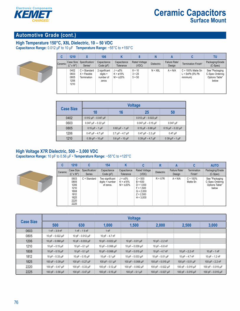
76
Ceramic CapacitorsSurface Mount
Automotive Grade (cont.) High Temperature 150°C, X8L Dielectric, 10 – 50 VDCCapacitance Range: 0.012 μF to 10 μF Temperature Range: −55°C to +150°C
Orde ing fo mation
C 1210 X 106 K 8 N A C TU
Ceramic Case Size (L" x W")
Specifi cation/Series1
Capacitance Code (pF)
Capacitance Tolerance
Rated Voltage (VDC) Dielectric Failure Rate/
Design Termination Finish2 Packaging/Grade (C-Spec)
04020603080512061210
C = StandardX = Flexible Termination
2 signifi cant digits +
number of zeros
J = ±5%K = ±10%M = ±20%
8 = 103 = 255 = 50
N = X8L A = N/A C = 100% Matte SnL = SnPb (5% Pb minimum)
See "Packaging C-Spec Ordering Options Table"
below
Case SizeVoltage
10 16 25 500402 0 012 µF – 0.047 µF 0.012 µF – 0.022 µF
0603 0.047 µF – 0.22 µF 0.047 µF – 0.15 µF 0.047 µF
0805 0.15 µF – 1 µF 0.82 µF – 1 µF 0.15 µF – 0.68 µF 0.15 µF – 0.22 µF
1206 0.47 µF – 4.7 µF 2.7 µF – 4.7 µF 0.47 µF – 2.2 µF 0.47 µF
1210 0.39 µF – 10 µF 5.6 µF – 10 µF 0.39 µF – 4.7 µF 0 39 µF – 1 µF
High Voltage X7R Dielectric, 500 – 3,000 VDCCapacitance Range: 10 pF to 0.56 μF • Temperature Range: −55°C to +125°C
K ME ’s Autom
emperature an a e cons ere em e atur El ctr nics I d stries A iance EIA) ch r te izes X7R die ec
d mic c uite s
p ng applic tions or for f quency di inating cir ts and sta of ca ce chara ics are R ex ts a predict e change i capacita h t m v ltage asts ma h n
nce bie t e c
tchi g ower l g i
s the e ect choi e de n o their se in po o s ar e in ind stri e to aut mo , te t ons, e ca y er sp ce
c gn t e t
ut d ito man
Auto on cs Coun cation r
O er ng Information
C 1210 C 154 K C R A C AUTO
Ceramic Case Size (L" x W")
Specifi cation/Series
Capacitance Code (pF)
Capacitance Tolerance
Rated Voltage (VDC) Dielectric Failure Rate/
DesignTermination
Finish1Packaging/Grade
(C-Spec)060308051206121018081812182522202225
C = Standard Two signifi cant digits + number
of zeros.
J = ±5%K = ±10%M = ±20%
C = 500 B = 630 D = 1,000 F = 1,500 G = 2,000 Z = 2,500 H = 3,000
R = X7R A = N/A C = 100% Matte Sn
See "Packaging C-Spec Ordering Options Table"
below
Case SizeVoltage
500 630 1,000 1,500 2,000 2,500 3,0000603 1 nF – 3.9 nF 1 nF – 1 5 nF 1 nF
0805 10 pF – 0.022 µF 10 pF – 0.012 µF 10 pF – 4.7 nF
1206 10 pF – 0.068 µF 10 pF – 0.033 µF 10 pF – 0.022 µF 10 pF – 0.01 µF 10 pF – 2.2 nF
1210 10 pF – 0.15 µF 10 pF – 0.1 µF 10 pF – 0.068 µF 10 pF – 0.039 µF 10 pF – 6.8 nF
1808 10 pF – 0.15 µF 10 pF – 0.1 µF 10 pF – 0.068 µF 10 pF – 0.015 µF 10 pF – 4.7 nF 10 pF – 2.2 nF 10 pF – 1 nF
1812 10 pF – 0.33 µF 10 pF – 0.15 µF 10 pF – 0.1 µF 10 pF – 0.033 µF 10 pF – 0.01 µF 10 pF – 4.7 nF 10 pF – 1.2 nF
1825 100 pF – 0.39 µF 100 pF – 0.27 µF 100 pF – 0.1 µF 100 pF – 0.068 µF 100 pF – 0.015 µF 100 pF – 0.01 µF 100 pF – 2.2 nF
2220 100 pF – 0.47 µF 100 pF – 0.33 µF 100 pF – 0.12 µF 100 pF – 0.082 µF 100 pF – 0.022 µF 100 pF – 0.015 µF 100 pF – 0.015 µF
2225 100 pF – 0.56 µF 100 pF – 0.47 µF 100 pF – 0.15 µF 100 pF – 0.1 µF 100 pF – 0.027 µF 100 pF – 0.015 µF 100 pF – 0.015 µF
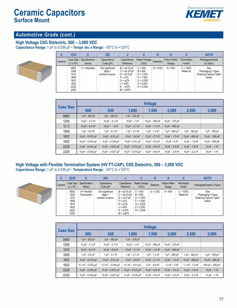
77
Ceramic CapacitorsSurface Mount
Automotive Grade (cont.)High Voltage C0G Dielectric, 500 – 3,000 VDCCapacitance Range: 1 pF to 0.039 μF • Tempe atu e Range: −55°C to +125°C
Order n nformationC 1210 C 332 J C G A C AUTO
Ceramic Case Size (L" x W")
Specifi cation/Series
Capacitance Code (pF)
Capacitance Tolerance1
Rated Voltage (VDC) Dielectric Failure Rate/
DesignTermination
Finish2Packaging/Grade
(C-Spec)08051206121018081812182522202225
C = Standard Two signifi cant digits +
number of zeros
B = ±0.10 pFC = ±0.25 pFD = ±0.5 pFF = ±1%G = ±2%J = ±5%K ±10%M = ±20%
C = 500 B = 630 D = 1,000 F = 1 500 G = 2,000 Z = 2,500 H = 3,000
G = C0G A = N/A C = 100% Matte Sn
See"Packaging C-Spec
Ordering Options Table" below
eng neers worldwid In s i
Case SizeVoltage
500 630 1,000 1,500 2,000 2,500 3,0000805 1 pF – 820 pF 1 pF – 560 pF 1 pF – 270 pF
1206 10 pF – 4 7 nF 10 pF – 4.7 nF 10 pF – 1 nF 10 pF – 560 pF 10 pF – 270 pF
12 0 10 pF – 8.2 nF 10 pF – 8 nF 10 pF – 2.7 nF 10 pF – 1.2 nF 10 pF – 680 pF
1808 1 pF – 6.8 nF 1 pF – 4.7 nF 1 pF – 2.7 nF 1 pF – 1 5 nF 1 pF – 680 pF 1 pF – 390 pF 1 pF – 180 pF
1812 10 pF – 0.015 µF 10 pF – 0.01 µF 10 pF – 5.6 nF 10 pF – 2.7 nF 10 pF – 1 5 nF 10 pF – 680 pF 10 pF – 390 pF
1825 10 pF – 0.033 µF 10 pF – 0.018 µF 10 pF – 0.01 µF 10 pF – 5.6 nF 10 pF – 3 nF 10 pF – 1.6 nF 10 pF – 680 pF
2220 10 pF – 0.033 µF 10 pF – 0.027 µF 10 pF – 0.012 µF 10 pF – 6.8 nF 10 pF – 3.9 nF 10 pF – 1.8 nF 10 pF – 1 nF
2225 10 pF – 0.039 µF 10 pF – 0 027 µF 10 pF – 0.015 µF 10 pF – 6.8 nF 10 pF – 3.9 nF 10 pF – 2.2 nF 10 pF – 1 nF
High Voltage with Flexible Termination System (HV FT-CAP), C0G Dielectric, 500 – 3,000 VDCCapacitance Range: 1 pF to 0.039 μF • Temperature Range: −55°C to +125°C
Order ng Information
C 2225 X 393 J C G A C AUTO
Ceramic Case Size (L" x W")
Specifi cation/Series
Capacitance Code (pF)
Capacitance Tolerance1
Rated Voltage (VDC) Dielectric Failure Rate/
DesignTermination
Finish2 Packaging/Grade (C-Spec)
08051206121018081812182522202225
X= Flexible Termination
Two signifi cant digits +
number of zeros.
B = ±0.10 pFC = ±0.25 pFD = ±0.5 pFF = ±1%G = ±2%J = ±5%K = ±10%M = ±20%
C = 500B = 630D = 1,000F = 1,500G = 2,000Z = 2,500H = 3,000
G = C0G A = N/A C = 100% Matte Sn
See“Packaging C-Spec
Ordering Options Table” below
w
KEMET’s A tomot ve G ade H gh Voltage w th Flexibl er in
he resul f e ess e tensile n r tress s ced dur n
r t l i s i val es ble n t e n tr , t s
e a ve silver epoxy tw en he nd n sy t m
is e tress mic which ca
R e t rm t
n , t rmi t n sys
Ts h u e mo Cs c a 1 m er ti e at d e m
vo tag pera r per ce of ll c ra lectr c a s. elec r c ca exh t no c t nce ect t ti e n ge a st gl gi
i
devi t ow E R at h requ ncie an d
f t t eir e n powe sup l es th c pacit widely se n
s t ot ) m l t r e m n s nd t t q i
het esi n rov d
circu t
C-Q200 q
Sur ace Mount Multila
H
Case SizeVoltage
500 630 1,000 1,500 2,000 2,500 3,0000805 1 pF – 820 pF 1 pF – 560 pF 1 pF – 270 pF
1206 10 pF – 4.7 nF 10 pF – 4.7 nF 10 pF – 1 nF 10 pF – 560 pF 10 pF – 270 pF
1210 10 pF – 8.2 nF 10 pF – 6.8 nF 10 pF – 2.7 nF 10 pF – 1.2 nF 10 pF – 680 pF
1808 1 pF – 6.8 nF 1 pF – 4.7 nF 1 pF – 2.7 nF 1 pF – 1 5 nF 1 pF – 680 pF 1 pF – 390 pF 1 pF – 180 pF
1812 10 pF – 0.015 µF 10 pF – 0.01 µF 10 pF – 5.6 nF 10 pF – 2.7 nF 10 pF – 1 5 nF 10 pF – 680 pF 10 pF – 390 pF
1825 9.1 nF – 0.033 µF 5.1 nF – 0.018 µF 5.1 nF – 0.01 µF 2 nF – 5.6 nF 1.3 nF – 3 nF 1.1 nF – 1.6 nF 430 pF – 680 pF
2220 10 pF – 0.033 µF 10 pF – 0.027 µF 10 pF – 0.012 µF 10 pF – 6.8 nF 10 pF – 3.9 nF 10 pF – 1.8 nF 10 pF – 1 nF
2225 10 pF – 0.039 µF 10 pF – 0.027 µF 10 pF – 0.015 µF 10 pF – 6.8 nF 10 pF – 3.9 nF 10 pF – 2.2 nF 10 pF – 1 nF
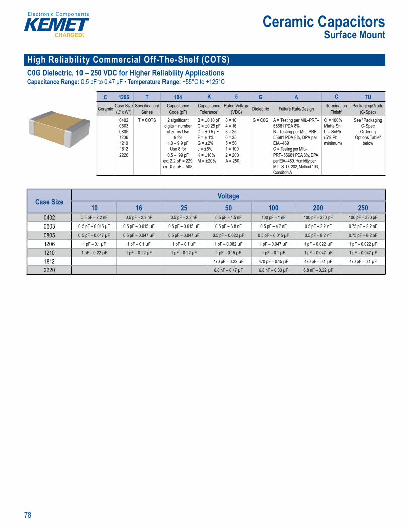
78
Ceramic CapacitorsSurface Mount
High Reliability Commercial Off-The-Shelf (COTS) C0G Dielectric, 10 – 250 VDC for Higher Reliability ApplicationsCapacitance Range: 0.5 pF to 0.47 μF • Temperature Range: −55°C to +125°C
y,
provides the fo lowing st evel o t ons and confo mance ce tifi cati
Ord ri g I formation
C 1206 T 104 K 5 G A C TU
Ceramic Case Size (L" x W")
Specifi cation/Series
Capacitance Code (pF)
Capacitance Tolerance1
Rated Voltage (VDC) Dielectric Failure Rate/Design Termination
Finish2Packaging/Grade
(C-Spec)0402060308051206121018122220
T = COTS 2 signifi cant digits + number
of zeros Use 9 for
1.0 – 9.9 pFUse 8 for
0.5 – .99 pFex. 2.2 pF = 229ex. 0.5 pF = 508
B = ±0.10 pFC = ±0.25 pFD = ±0 5 pFF = ± 1%G = ±2%J = ±5%K = ±10%M = ±20%
8 = 104 = 163 = 256 = 355 = 501 = 1002 = 200A = 250
G = C0G A = Testing per MIL–PRF–55681 PDA 8%B= Testing per MIL–PRF–55681 PDA 8%, DPA per EIA–469C = Testing per MIL–PRF–55681 PDA 8%, DPA per EIA–469, Humidity per M L–STD–202, Method 103, Condition A
C = 100% Matte SnL = SnPb (5% Pb minimum)
See "Packaging C-Spec Ordering
Options Table" below
Case SizeVoltage
10 16 25 50 100 200 2500402 0.5 pF – 2.2 nF 0.5 pF – 2.2 nF 0.5 pF – 2.2 nF 0.5 pF – 1.5 nF 100 pF – 1 nF 100 pF – 330 pF 100 pF – 330 pF
0603 0 5 pF – 0.015 µF 0 5 pF – 0.015 µF 0 5 pF – 0.015 µF 0.5 pF – 6.8 nF 0.5 pF – 4.7 nF 0.5 pF – 2.2 nF 0.75 pF – 2 2 nF
0805 0 5 pF – 0.047 µF 0 5 pF – 0.047 µF 0 5 pF – 0.047 µF 0.5 pF – 0.022 µF 0 5 pF – 0.015 µF 0.5 pF – 8.2 nF 0.75 pF – 8 2 nF
1206 1 pF – 0.1 µF 1 pF – 0.1 µF 1 pF – 0.1 µF 1 pF – 0.082 µF 1 pF – 0.047 µF 1 pF – 0.022 µF 1 pF – 0.022 µF
1210 1 pF – 0 22 µF 1 pF – 0 22 µF 1 pF – 0 22 µF 1 pF – 0.15 µF 1 pF – 0.1 µF 1 pF – 0.047 µF 1 pF – 0.047 µF
1812 470 pF – 0.22 µF 470 pF – 0.15 µF 470 pF – 0.1 µF 470 pF – 0.1 µF
2220 6.8 nF – 0.47 µF 6.8 nF – 0.33 µF 6.8 nF – 0.22 µF
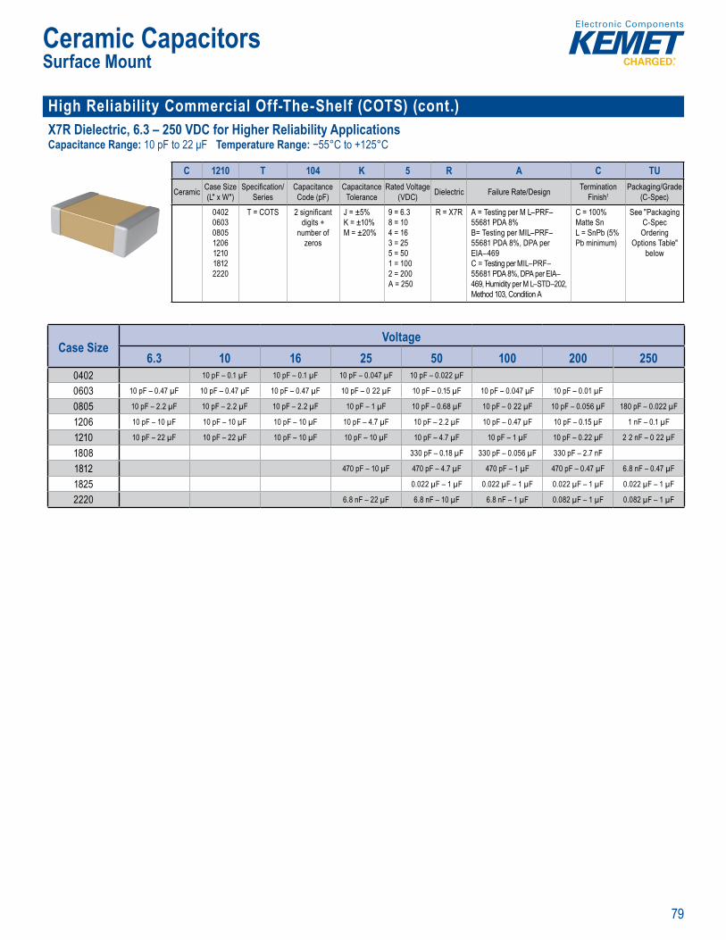
79
Ceramic CapacitorsSurface Mount
High Reliability Commercial Off-The-Shelf (COTS) (cont.)X7R Dielectric, 6.3 – 250 VDC for Higher Reliability ApplicationsCapacitance Range: 10 pF to 22 μF Temperature Range: −55°C to +125°C
ct to
capacitance with ref en c
provides the fol owng t st level ptons d confo mance cert fi cation
O deri g Information
C 1210 T 104 K 5 R A C TU
Ceramic Case Size (L" x W")
Specifi cation/Series
Capacitance Code (pF)
Capacitance Tolerance
Rated Voltage (VDC) Dielectric Failure Rate/Design Termination
Finish1Packaging/Grade
(C-Spec)
0402060308051206121018122220
T = COTS 2 signifi cant digits +
number of zeros
J = ±5%K = ±10%M = ±20%
9 = 6.38 = 104 = 163 = 255 = 501 = 1002 = 200A = 250
R = X7R A = Testing per M L–PRF–55681 PDA 8%B= Testing per MIL–PRF–55681 PDA 8%, DPA per EIA–469C = Testing per MIL–PRF–55681 PDA 8%, DPA per EIA–469, Humidity per M L–STD–202, Method 103, Condition A
C = 100% Matte SnL = SnPb (5% Pb minimum)
See "Packaging C-Spec Ordering
Options Table" below
Case SizeVoltage
6.3 10 16 25 50 100 200 2500402 10 pF – 0.1 µF 10 pF – 0.1 µF 10 pF – 0.047 µF 10 pF – 0.022 µF
0603 10 pF – 0.47 µF 10 pF – 0.47 µF 10 pF – 0.47 µF 10 pF – 0 22 µF 10 pF – 0.15 µF 10 pF – 0.047 µF 10 pF – 0.01 µF
0805 10 pF – 2.2 µF 10 pF – 2.2 µF 10 pF – 2.2 µF 10 pF – 1 µF 10 pF – 0.68 µF 10 pF – 0 22 µF 10 pF – 0.056 µF 180 pF – 0.022 µF
1206 10 pF – 10 µF 10 pF – 10 µF 10 pF – 10 µF 10 pF – 4.7 µF 10 pF – 2.2 µF 10 pF – 0.47 µF 10 pF – 0.15 µF 1 nF – 0.1 µF
1210 10 pF – 22 µF 10 pF – 22 µF 10 pF – 10 µF 10 pF – 10 µF 10 pF – 4.7 µF 10 pF – 1 µF 10 pF – 0.22 µF 2 2 nF – 0 22 µF
1808 330 pF – 0.18 µF 330 pF – 0.056 µF 330 pF – 2.7 nF
1812 470 pF – 10 µF 470 pF – 4.7 µF 470 pF – 1 µF 470 pF – 0.47 µF 6.8 nF – 0.47 µF
1825 0.022 µF – 1 µF 0.022 µF – 1 µF 0.022 µF – 1 µF 0.022 µF – 1 µF
2220 6.8 nF – 22 µF 6.8 nF – 10 µF 6.8 nF – 1 µF 0.082 µF – 1 µF 0.082 µF – 1 µF

80
Ceramic CapacitorsSurface Mount
SnPb End Metallization C0G Dielectric, 10 – 250 VDC (Commercial Grade)Capacitance Range: 0.5 pF to 0.47 μF • Temperature Range: −55°C to +125°C
Ord ri g I formation
C 1206 C 104 J 3 G A L TU
Ceramic Case Size (L" x W")
Specifi cation/Series
Capacitance Code (pF)
Capacitance Tolerance1
Rated Voltage (VDC) Dielectric Failure Rate/
DesignTermination
Finish2Packaging/Grade
(C-Spec)
0402060308051206121018081812182522202225
C = Standard Two signifi cant digits +
number of zeros.Use 9 for 1.0 – 9.9 pFUse 8 for 0.5 – 99 pF
ex. 2.2 pF = 229ex. 0.5 pF = 508
B = ±0.10 pFC = ±0.25 pFD = ±0.5 pFF = ±1%G = ±2%J = ±5%K = ±10%M = ±20%
8 = 10 4 = 16 3 = 25 5 = 50 1 = 100 2 = 200 A = 250
G = C0G A = N/A L = SnPb (5% Pb minimum)
See “Packaging C-Spec Ordering
Options Table” below
±1% ±2
Case SizeVoltage
10 16 25 50 100 200 2500402 0 5 pF – 2 2 nF 0.5 pF – 2.2 nF 0.5 pF – 2.2 nF 0.5 pF – 1.5 nF 100 pF – 1 nF 100 pF – 330 pF 100 pF – 330 pF
0603 0.5 pF – 0.015 µF 0.5 pF – 0.015 µF 0.5 pF – 0.015 µF 0.5 pF – 6.8 nF 0.5 pF – 4.7 nF 0 5 pF – 2.2 nF 0.75 pF – 2.2 nF
0805 0.5 pF – 0.047 µF 0.5 pF – 0.047 µF 0 5 pF – 0.047 µF 0.5 pF – 0.022 µF 0.5 pF – 0.015 µF 0 5 pF – 8.2 nF 0.75 pF – 8.2 nF
1206 1 pF – 0.1 µF 1 pF – 0.1 µF 1 pF – 0.1 µF 1 pF – 0.082 µF 1 pF – 0.047 µF 1 pF – 0.022 µF 1 pF – 0.022 µF
1210 1 pF – 0.22 µF 1 pF – 0.22 µF 1 pF – 0 22 µF 1 pF – 0.15 µF 1 pF – 0.1 µF 1 pF – 0.047 µF 1 pF – 0.047 µF
1808 330 pF – 4.7 nF 330 pF – 4.7 nF 330 pF – 2.7 nF 330 pF – 2.7 nF
1812 470 pF – 0 22 µF 470 pF – 0.15 µF 470 pF – 0.1 µF 470 pF – 0.1 µF
1825 3.9 nF – 0.027 µF 3.9 nF – 0.027 µF 3.9 nF – 0.012 µF 3.9 nF – 0.012 µF
2220 6.8 nF – 0.47 µF 6.8 nF – 0.33 µF 6.8 nF – 0 22 µF
2225 4.7 nF – 0.033 µF 4.7 nF – 0.027 µF 4.7 nF – 0.015 µF 4.7 nF – 0.015 µF
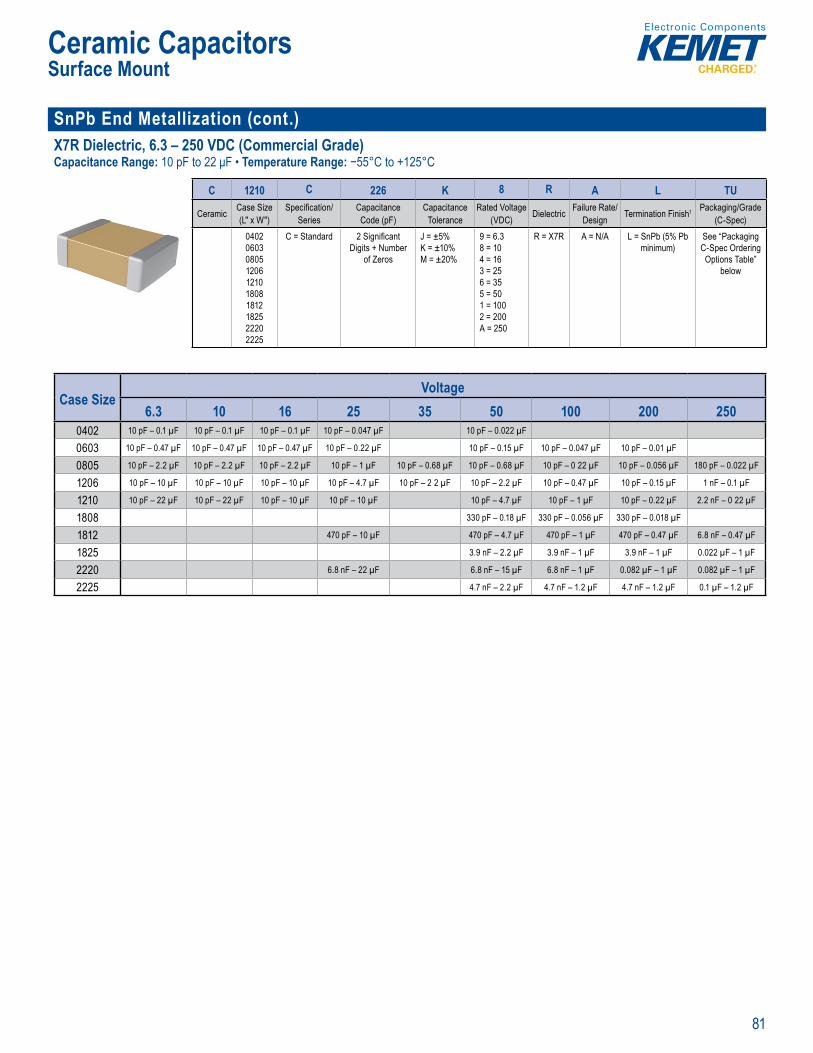
81
Ceramic CapacitorsSurface Mount
SnPb End Metallization (cont.)X7R Dielectric, 6.3 – 250 VDC (Commercial Grade)Capacitance Range: 10 pF to 22 μF • Temperature Range: −55°C to +125°C
O deri Informa ion
C 1210 C 226 K 8 R A L TU
Ceramic Case Size (L" x W")
Specifi cation/Series
Capacitance Code (pF)
Capacitance Tolerance
Rated Voltage (VDC) Dielectric Failure Rate/
Design Termination Finish1 Packaging/Grade (C-Spec)
0402060308051206121018081812182522202225
C = Standard 2 Signifi cant Digits + Number
of Zeros
J = ±5%K = ±10%M = ±20%
9 = 6.38 = 104 = 163 = 256 = 355 = 501 = 1002 = 200A = 250
R = X7R A = N/A L = SnPb (5% Pb minimum)
See “Packaging C-Spec Ordering
Options Table” below
• Reliable and robust te • E A 402 0 0 0
Case SizeVoltage
6.3 10 16 25 35 50 100 200 2500402 10 pF – 0.1 µF 10 pF – 0.1 µF 10 pF – 0.1 µF 10 pF – 0.047 µF 10 pF – 0.022 µF
0603 10 pF – 0.47 µF 10 pF – 0.47 µF 10 pF – 0.47 µF 10 pF – 0.22 µF 10 pF – 0.15 µF 10 pF – 0.047 µF 10 pF – 0.01 µF
0805 10 pF – 2.2 µF 10 pF – 2.2 µF 10 pF – 2.2 µF 10 pF – 1 µF 10 pF – 0.68 µF 10 pF – 0.68 µF 10 pF – 0 22 µF 10 pF – 0.056 µF 180 pF – 0.022 µF
1206 10 pF – 10 µF 10 pF – 10 µF 10 pF – 10 µF 10 pF – 4.7 µF 10 pF – 2 2 µF 10 pF – 2.2 µF 10 pF – 0.47 µF 10 pF – 0.15 µF 1 nF – 0.1 µF
1210 10 pF – 22 µF 10 pF – 22 µF 10 pF – 10 µF 10 pF – 10 µF 10 pF – 4.7 µF 10 pF – 1 µF 10 pF – 0.22 µF 2.2 nF – 0 22 µF
1808 330 pF – 0.18 µF 330 pF – 0.056 µF 330 pF – 0.018 µF
1812 470 pF – 10 µF 470 pF – 4.7 µF 470 pF – 1 µF 470 pF – 0.47 µF 6.8 nF – 0.47 µF
1825 3.9 nF – 2.2 µF 3.9 nF – 1 µF 3.9 nF – 1 µF 0.022 µF – 1 µF
2220 6.8 nF – 22 µF 6.8 nF – 15 µF 6.8 nF – 1 µF 0.082 µF – 1 µF 0.082 µF – 1 µF
2225 4.7 nF – 2.2 µF 4.7 nF – 1.2 µF 4.7 nF – 1.2 µF 0.1 µF – 1.2 µF
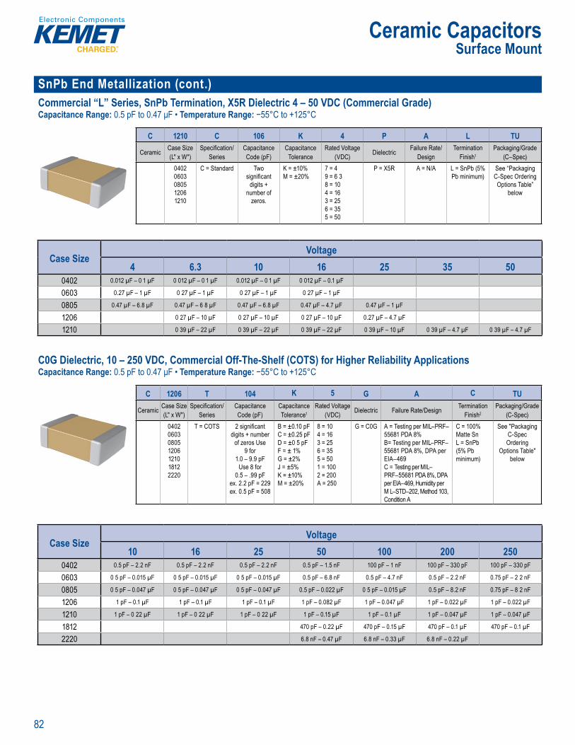
82
Ceramic CapacitorsSurface Mount
SnPb End Metallization (cont.)Commercial “L” Series, SnPb Termination, X5R Dielectric 4 – 50 VDC (Commercial Grade)Capacitance Range: 0.5 pF to 0.47 μF • Temperature Range: −55°C to +125°C
rd ri g fo m ti n
C 1210 C 106 K 4 P A L TU
Ceramic Case Size (L" x W")
Specifi cation/Series
Capacitance Code (pF)
Capacitance Tolerance
Rated Voltage (VDC) Dielectric Failure Rate/
DesignTermination
Finish1Packaging/Grade
(C–Spec)04020603080512061210
C = Standard Two signifi cant
digits + number of
zeros.
K = ±10%M = ±20%
7 = 49 = 6 38 = 104 = 163 = 256 = 355 = 50
P = X5R A = N/A L = SnPb (5% Pb minimum)
See “Packaging C-Spec Ordering
Options Table” below
Case SizeVoltage
4 6.3 10 16 25 35 500402 0.012 µF – 0 1 µF 0 012 µF – 0 1 µF 0.012 µF – 0 1 µF 0 012 µF – 0.1 µF
0603 0.27 µF – 1 µF 0 27 µF – 1 µF 0 27 µF – 1 µF 0 27 µF – 1 µF
0805 0.47 µF – 6.8 µF 0.47 µF – 6 8 µF 0.47 µF – 6.8 µF 0.47 µF – 4.7 µF 0.47 µF – 1 µF
1206 0 27 µF – 10 µF 0 27 µF – 10 µF 0 27 µF – 10 µF 0.27 µF – 4.7 µF
1210 0 39 µF – 22 µF 0 39 µF – 22 µF 0 39 µF – 22 µF 0 39 µF – 10 µF 0 39 µF – 4.7 µF 0 39 µF – 4.7 µF
C0G Dielectric, 10 – 250 VDC, Commercial Off-The-Shelf (COTS) for Higher Reliability ApplicationsCapacitance Range: 0.5 pF to 0.47 μF • Temperature Range: −55°C to +125°C
of high relia l ty test regimes an requirements KEME r g larly uppl es p- c eened” products by worki w th c stomer dr i
r s the h gh m
en ro ts, ut at lo er c t t t to er. h s ccompli ed y eli ng the or cu tom ecifi c dra i l e u
and en selecte pr vide t ondi ening n e
i
or h tab
h re t me volt a ts e l e in c pa t r fere ce t t tem r t re ance c ang ed to ±30 p m m -55 C to +12
i MI –P F 56 e an d rel E ET l o
Rel abi ity
Ord ri g I formation
C 1206 T 104 K 5 G A C TU
Ceramic Case Size (L" x W")
Specifi cation/Series
Capacitance Code (pF)
Capacitance Tolerance1
Rated Voltage (VDC) Dielectric Failure Rate/Design Termination
Finish2Packaging/Grade
(C-Spec)0402060308051206121018122220
T = COTS 2 signifi cant digits + number
of zeros Use 9 for
1.0 – 9.9 pFUse 8 for
0.5 – .99 pFex. 2.2 pF = 229ex. 0.5 pF = 508
B = ±0.10 pFC = ±0.25 pFD = ±0 5 pFF = ± 1%G = ±2%J = ±5%K = ±10%M = ±20%
8 = 104 = 163 = 256 = 355 = 501 = 1002 = 200A = 250
G = C0G A = Testing per MIL–PRF–55681 PDA 8%B= Testing per MIL–PRF–55681 PDA 8%, DPA per EIA–469C = Testing per MIL–PRF–55681 PDA 8%, DPA per EIA–469, Humidity per M L–STD–202, Method 103, Condition A
C = 100% Matte SnL = SnPb (5% Pb minimum)
See "Packaging C-Spec Ordering
Options Table" below
D
8% PDA 8%
f DPA
85/85
Case SizeVoltage
10 16 25 50 100 200 2500402 0.5 pF – 2.2 nF 0.5 pF – 2.2 nF 0.5 pF – 2.2 nF 0.5 pF – 1.5 nF 100 pF – 1 nF 100 pF – 330 pF 100 pF – 330 pF
0603 0 5 pF – 0.015 µF 0 5 pF – 0.015 µF 0 5 pF – 0.015 µF 0.5 pF – 6.8 nF 0.5 pF – 4.7 nF 0.5 pF – 2.2 nF 0.75 pF – 2 2 nF
0805 0 5 pF – 0.047 µF 0 5 pF – 0.047 µF 0 5 pF – 0.047 µF 0.5 pF – 0.022 µF 0 5 pF – 0.015 µF 0.5 pF – 8.2 nF 0.75 pF – 8 2 nF
1206 1 pF – 0.1 µF 1 pF – 0.1 µF 1 pF – 0.1 µF 1 pF – 0.082 µF 1 pF – 0.047 µF 1 pF – 0.022 µF 1 pF – 0.022 µF
1210 1 pF – 0 22 µF 1 pF – 0 22 µF 1 pF – 0 22 µF 1 pF – 0.15 µF 1 pF – 0.1 µF 1 pF – 0.047 µF 1 pF – 0.047 µF
1812 470 pF – 0.22 µF 470 pF – 0.15 µF 470 pF – 0.1 µF 470 pF – 0.1 µF
2220 6.8 nF – 0.47 µF 6.8 nF – 0.33 µF 6.8 nF – 0.22 µF
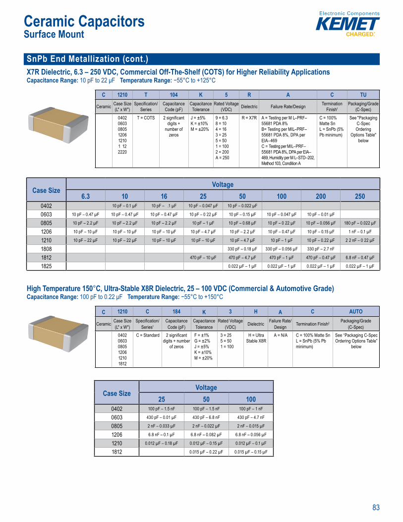
83
Ceramic CapacitorsSurface Mount
SnPb End Metallization (cont.)X7R Dielectric, 6.3 – 250 VDC, Commercial Off-The-Shelf (COTS) for Higher Reliability ApplicationsCapacitance Range: 10 pF to 22 μF Temperature Range: −55°C to +125°C
ct to
capacitance with ref en c
provides the llowing tes e
O derin Information
C 1210 T 104 K 5 R A C TU
Ceramic Case Size (L" x W")
Specifi cation/Series
Capacitance Code (pF)
Capacitance Tolerance
Rated Voltage (VDC) Dielectric Failure Rate/Design Termination
Finish1Packaging/Grade
(C-Spec)
040206030805120612101 122220
T = COTS 2 signifi cant digits +
number of zeros
J = ±5%K = ±10%M = ±20%
9 = 6.38 = 104 = 163 = 255 = 501 = 1002 = 200A = 250
R = X7R A = Testing per M L–PRF–55681 PDA 8%B= Testing per MIL–PRF–55681 PDA 8%, DPA per EIA–469C = Testing per MIL–PRF–55681 PDA 8%, DPA per EIA–469, Humidity per M L–STD–202, Method 103, Condition A
C = 100% Matte SnL = SnPb (5% Pb minimum)
See "Packaging C-Spec Ordering
Options Table" below
Case SizeVoltage
6.3 10 16 25 50 100 200 2500402 10 pF – 0.1 µF 10 pF – .1 µF 10 pF – 0.047 µF 10 pF – 0.022 µF
0603 10 pF – 0.47 µF 10 pF – 0.47 µF 10 pF – 0.47 µF 10 pF – 0 22 µF 10 pF – 0.15 µF 10 pF – 0.047 µF 10 pF – 0.01 µF
0805 10 pF – 2.2 µF 10 pF – 2.2 µF 10 pF – 2.2 µF 10 pF – 1 µF 10 pF – 0.68 µF 10 pF – 0 22 µF 10 pF – 0.056 µF 180 pF – 0.022 µF
1206 10 pF – 10 µF 10 pF – 10 µF 10 pF – 10 µF 10 pF – 4.7 µF 10 pF – 2.2 µF 10 pF – 0.47 µF 10 pF – 0.15 µF 1 nF – 0.1 µF
1210 10 pF – 22 µF 10 pF – 22 µF 10 pF – 10 µF 10 pF – 10 µF 10 pF – 4.7 µF 10 pF – 1 µF 10 pF – 0.22 µF 2 2 nF – 0 22 µF
1808 330 pF – 0.18 µF 330 pF – 0.056 µF 330 pF – 2.7 nF
1812 470 pF – 10 µF 470 pF – 4.7 µF 470 pF – 1 µF 470 pF – 0.47 µF 6.8 nF – 0.47 µF
1825 0.022 µF – 1 µF 0.022 µF – 1 µF 0.022 µF – 1 µF 0.022 µF – 1 µF
High Temperature 150°C, Ultra-Stable X8R Dielectric, 25 – 100 VDC (Commercial & Automotive Grade)Capacitance Range: 100 pF to 0.22 μF Temperature Range: −55°C to +150°C
Overvi w
M Ult a X8 c fe 5 - er t g t m rature, o eri g t e est h g empe
e di c ric te logy a iabil ty fo treme te a- ation of ers th me tempe tur cap i y
tiona the ca tance lo ue DC le X8 ib t no c n n e m l
apa at re. b e a er
tab ic c de
p licat ons re ia li y an acit ce stab at i e g e u e r a co n. se c p s
y
d c ve ces Automot Electro ics
Counc ’ Q2 qu li cat emen
2 – C (
Ordering nformation
C 1210 C 184 K 3 H A C AUTO
Ceramic Case Size (L" x W")
Specifi cation/Series1
Capacitance Code (pF)
Capacitance Tolerance
Rated Voltage (VDC) Dielectric Failure Rate/
Design Termination Finish2 Packaging/Grade (C-Spec)
040206030805120612101812
C = Standard 2 signifi cant digits + number
of zeros
F = ±1%G = ±2%J = ±5%K = ±10%M = ±20%
3 = 255 = 501 = 100
H = Ultra Stable X8R
A = N/A C = 100% Matte SnL = SnPb (5% Pb minimum)
See “Packaging C-Spec Ordering Options Table”
below
Case SizeVoltage
25 50 1000402 100 pF – 1.5 nF 100 pF – 1.5 nF 100 pF – 1 nF
0603 430 pF – 0.01 µF 430 pF – 6.8 nF 430 pF – 4.7 nF
0805 2 nF – 0.033 µF 2 nF – 0.022 µF 2 nF – 0.015 µF
1206 6.8 nF – 0.1 µF 6.8 nF – 0.082 µF 6.8 nF – 0.056 µF
1210 0.012 µF – 0.18 µF 0.012 µF – 0.15 µF 0.012 µF – 0.1 µF
1812 0.015 µF – 0.22 µF 0.015 µF – 0.15 µF
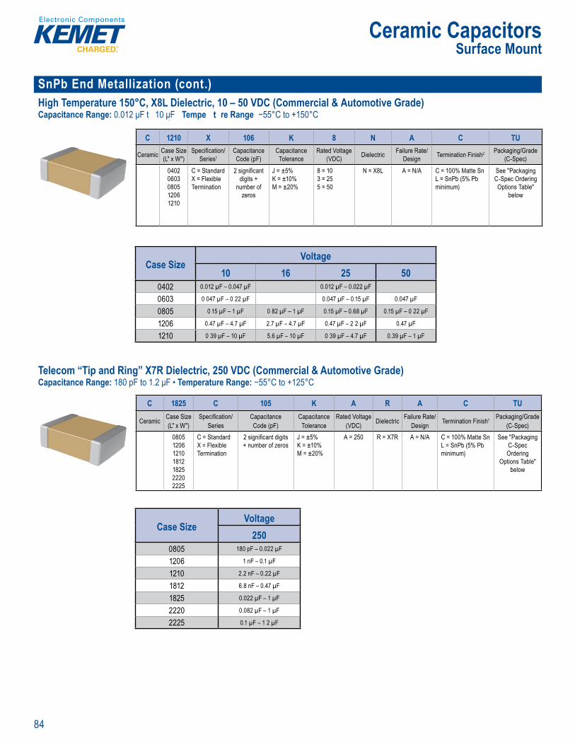
84
Ceramic CapacitorsSurface Mount
SnPb End Metallization (cont.)High Temperature 150°C, X8L Dielectric, 10 – 50 VDC (Commercial & Automotive Grade)Capacitance Range: 0.012 μF t 10 μF Tempe t re Range −55°C to +150°C
Ordering nformation
C 1210 X 106 K 8 N A C TU
Ceramic Case Size (L" x W")
Specifi cation/Series1
Capacitance Code (pF)
Capacitance Tolerance
Rated Voltage (VDC) Dielectric Failure Rate/
Design Termination Finish2 Packaging/Grade (C-Spec)
04020603080512061210
C = StandardX = Flexible Termination
2 signifi cant digits +
number of zeros
J = ±5%K = ±10%M = ±20%
8 = 103 = 255 = 50
N = X8L A = N/A C = 100% Matte SnL = SnPb (5% Pb minimum)
See "Packaging C-Spec Ordering Options Table"
below
Case SizeVoltage
10 16 25 500402 0.012 µF – 0.047 µF 0.012 µF – 0.022 µF
0603 0 047 µF – 0 22 µF 0.047 µF – 0.15 µF 0.047 µF
0805 0 15 µF – 1 µF 0 82 µF – 1 µF 0.15 µF – 0.68 µF 0.15 µF – 0 22 µF
1206 0.47 µF – 4.7 µF 2.7 µF – 4.7 µF 0.47 µF – 2 2 µF 0.47 µF
1210 0 39 µF – 10 µF 5.6 µF – 10 µF 0 39 µF – 4.7 µF 0.39 µF – 1 µF
Telecom “Tip and Ring” X7R Dielectric, 250 VDC (Commercial & Automotive Grade)Capacitance Range: 180 pF to 1.2 μF • Temperature Range: −55°C to +125°C
I , 1 ase sizes g l o r m z i st % pure t d te min ish that lo
lent s y er sh o ti avai po e uest
des gned an a ed for l
i ass a 16 25 Hz AC signal uls f 70 V ms t 90 Vrms Serv ng
as an xcel en eplacement for high vol age leaded fi lm devi
ar ce wh ti eati
EMET ip and capac eature a maximu emp u e a d are o s dere m at e
on c us r es All EIA cterizes s a s II mater om onen of his c a t o
X7R dielectric ex ib ts a pre
lim o +
T devices b e to today’s h gh d-free re sin te u es a e uperi r h gh u cy lt ri
Or er ng Information
C 1825 C 105 K A R A C TU
Ceramic Case Size (L" x W")
Specifi cation/Series
Capacitance Code (pF)
Capacitance Tolerance
Rated Voltage (VDC) Dielectric Failure Rate/
Design Termination Finish1 Packaging/Grade (C-Spec)
0805120612101812182522202225
C = StandardX = Flexible Termination
2 signifi cant digits + number of zeros
J = ±5%K = ±10%M = ±20%
A = 250 R = X7R A = N/A C = 100% Matte SnL = SnPb (5% Pb minimum)
See "Packaging C-Spec Ordering
Options Table" below
Case SizeVoltage
2500805 180 pF – 0.022 µF
1206 1 nF – 0.1 µF
1210 2.2 nF – 0.22 µF
1812 6.8 nF – 0.47 µF
1825 0.022 µF – 1 µF
2220 0.082 µF – 1 µF
2225 0.1 µF – 1 2 µF
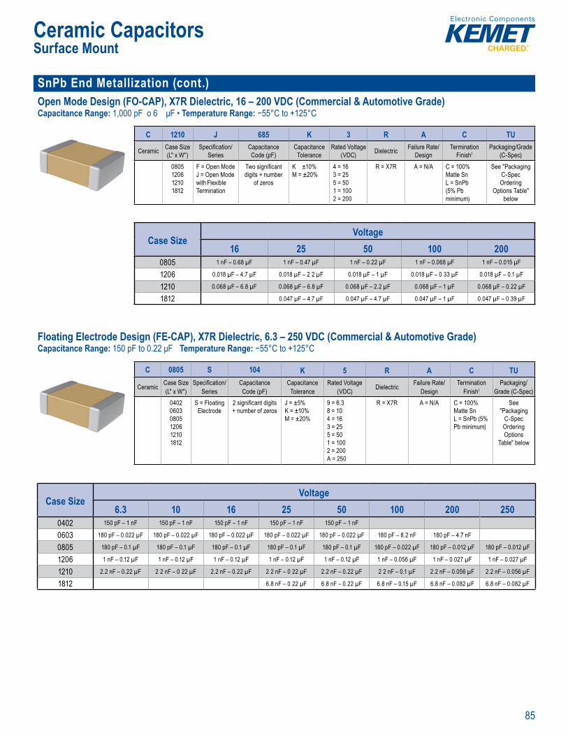
85
Ceramic CapacitorsSurface Mount
SnPb End Metallization (cont.)Open Mode Design (FO-CAP), X7R Dielectric, 16 – 200 VDC (Commercial & Automotive Grade)Capacitance Range: 1,000 pF o 6 μF • Temperature Range: −55°C to +125°C
cyc ng hese d v ces termination technology w
t
Order ng I ormation
C 1210 J 685 K 3 R A C TU
Ceramic Case Size (L" x W")
Specifi cation/Series
Capacitance Code (pF)
Capacitance Tolerance
Rated Voltage (VDC) Dielectric Failure Rate/
DesignTermination
Finish1Packaging/Grade
(C-Spec)0805120612101812
F = Open ModeJ = Open Mode with Flexible Termination
Two signifi cant digits + number
of zeros
K ±10%M = ±20%
4 = 163 = 255 = 501 = 1002 = 200
R = X7R A = N/A C = 100% Matte SnL = SnPb (5% Pb minimum)
See "Packaging C-Spec Ordering
Options Table" below
Case SizeVoltage
16 25 50 100 2000805 1 nF – 0.68 µF 1 nF – 0.47 µF 1 nF – 0.22 µF 1 nF – 0.068 µF 1 nF – 0.015 µF
1206 0.018 µF – 4.7 µF 0.018 µF – 2 2 µF 0.018 µF – 1 µF 0.018 µF – 0 33 µF 0.018 µF – 0.1 µF
1210 0.068 µF – 6.8 µF 0.068 µF – 6.8 µF 0.068 µF – 2.2 µF 0.068 µF – 1 µF 0.068 µF – 0.22 µF
1812 0.047 µF – 4.7 µF 0.047 µF – 4.7 µF 0.047 µF – 1 µF 0.047 µF – 0 39 µF
Floating Electrode Design (FE-CAP), X7R Dielectric, 6.3 – 250 VDC (Commercial & Automotive Grade)Capacitance Range: 150 pF to 0.22 μF Temperature Range: −55°C to +125°C
capaci or in X7R d elec i
single mo lithic structure This u iqu onfi gu ation esu ts in en anced vol a e and ESD performance over t nd rd ca a
a acke a ce m ce
apa ita a sho t ike y. T e A is esigne e ce keliho w IR or s cuit
d the ance for a cat ophic and po nt a l cos
T 1 49:20 fi lt ectr
valu s These devices exhibit a pre
an d o +1
add Comm Grade otive ev ces a e w ich the de d n Auto e Electron cs Co quireme
Ordering nformation
C 0805 S 104 K 5 R A C TU
Ceramic Case Size (L" x W")
Specifi cation/Series
Capacitance Code (pF)
Capacitance Tolerance
Rated Voltage (VDC) Dielectric Failure Rate/
DesignTermination
Finish1Packaging/
Grade (C-Spec)040206030805120612101812
S = Floating Electrode
2 signifi cant digits + number of zeros
J = ±5%K = ±10%M = ±20%
9 = 6.38 = 104 = 163 = 255 = 501 = 1002 = 200A = 250
R = X7R A = N/A C = 100% Matte SnL = SnPb (5% Pb minimum)
See "Packaging
C-Spec Ordering Options
Table" below
Case SizeVoltage
6.3 10 16 25 50 100 200 2500402 150 pF – 1 nF 150 pF – 1 nF 150 pF – 1 nF 150 pF – 1 nF 150 pF – 1 nF
0603 180 pF – 0.022 µF 180 pF – 0.022 µF 180 pF – 0.022 µF 180 pF – 0.022 µF 180 pF – 0.022 µF 180 pF – 8.2 nF 180 pF – 4.7 nF
0805 180 pF – 0.1 µF 180 pF – 0.1 µF 180 pF – 0.1 µF 180 pF – 0.1 µF 180 pF – 0.1 µF 180 pF – 0.022 µF 180 pF – 0.012 µF 180 pF – 0.012 µF
1206 1 nF – 0.12 µF 1 nF – 0.12 µF 1 nF – 0.12 µF 1 nF – 0.12 µF 1 nF – 0.12 µF 1 nF – 0.056 µF 1 nF – 0.027 µF 1 nF – 0.027 µF
1210 2.2 nF – 0.22 µF 2 2 nF – 0 22 µF 2.2 nF – 0.22 µF 2 2 nF – 0 22 µF 2.2 nF – 0.22 µF 2 2 nF – 0.1 µF 2.2 nF – 0.056 µF 2.2 nF – 0.056 µF
1812 6.8 nF – 0 22 µF 6.8 nF – 0.22 µF 6.8 nF – 0.15 µF 6.8 nF – 0.082 µF 6.8 nF – 0.082 µF

86
Ceramic CapacitorsSurface Mount
SnPb End Metallization (cont.)Flexible Termination System (FT-CAP) X7R Dielectric, 6.3 – 250 VDC (Commercial & Automotive Grade)Capacitance Range: 180 pF to 22 μF • Tempera u e Range −55°C to +125°C
Orderin nformat on
C 1206 X 106 K 4 R A C TU
Ceramic Case Size (L" x W")
Specifi cation/Series
Capacitance Code (pF)
Capacitance Tolerance
Rated Voltage (VDC) Dielectric Failure Rate/
DesignTermination
Finish1Packaging/Grade
(C-Spec)2
060308051206121018081812182522202225
X = Flexible Termination
2 signifi cant digits +
number of zeros
J = ±5%K = ±10%M = ±20%
9 = 6.38 = 104 = 163 = 255 = 501 = 1002 = 200A = 250
R = X7R A = N/A C = 100% Matte SnL = SnPb (5% Pb minimum)
See "Packaging
C-Spec Ordering
Options Table" below
Case SizeVoltage
6.3 10 16 25 50 100 200 2500603 180 pF – 0.47 µF 180 pF – 0.47 µF 180 pF – 0 47 µF 180 pF – 0 22 µF 180 pF – 0.15 µF 180 pF – 0.047 µF 180 pF – 0.01 µF
0805 180 pF – 2.2 µF 180 pF – 2 2 µF 180 pF – 2.2 µF 180 pF – 1 µF 180 pF – 0.68 µF 180 pF – 0.22 µF 180 pF – 0.056 µF 180 pF – 0.022 µF
1206 470 pF – 10 µF 470 pF – 10 µF 470 pF – 10 µF 470 pF – 4.7 µF 470 pF – 2.2 µF 1 nF – 0.47 µF 1 nF – 0.15 µF 1 nF – 0.1 µF
1210 2.2 nF – 22 µF 2 2 nF – 22 µF 2.2 nF – 10 µF 2.2 nF – 10 µF 2.2 nF – 4.7 µF 2.2 nF – 1 µF 2 2 nF – 0 22 µF 2.2 nF – 0.22 µF
1808 4.7 nF – 0.18 µF 4.7 nF – 0.056 µF 4.7 nF – 0.018 µF
1812 6 8 nF – 10 µF 6.8 nF – 4.7 µF 6.8 nF – 1 µF 6.8 nF – 0.47 µF 6.8 nF – 0.47 µF
1825 0.022 µF – 2.2 µF 0.022 µF – 1 µF 0.022 µF – 1 µF 0.022 µF – 1 µF
2220 0.082 µF – 22 µF 0.082 µF – 15 µF 0.082 µF – 1 µF 0.082 µF – 1 µF 0.082 µF – 1 µF
2225 0.047 µF – 2.2 µF 0.047 µF – 1.2 µF 0.047 µF – 1.2 µF 0.047 µF – 1.2 µF
Floating Electrode Design with Flexible Termination System (FF-CAP), X7R Dielectric, 6.3 – 250 VDC (Commercial & Automotive Grade)Capacitance Range: 180 pF to 0.22 μF Temperature Range: −55°C to +125°C
Sur ace M unt Multil ye
loat ng E ect ode Design wi h lexible Termi at on ystem(F CA ), X7R Die ectric 6. – 0 D
verv w
loati lectrode w F exible Te n t on c om i i EME te logies g d F he fl
u i i o fo
s ruc olta
cke
sh ain l t sold ity an e ectric erf rmance B echno ogies add e rima y fai ode of LCC x c acks, wh
e y e s t es e le s r tre e
g extr me
vel o p otect o
es y r ultim f l f d p miz hes de xhi it
respect to and volt ence to
1 %
Ordering nformation
C 0805 Y 104 K 5 R A C TU
Ceramic Case Size (L" x W")
Specifi cation/Series
Capacitance Code (pF)
Capacitance Tolerance
Rated Voltage (VDC) Dielectric Failure Rate/
DesignTermination
Finish1Packaging/
Grade (C-Spec)06030805120612101812
Y = Floating Electrode with Flexible Termination
2 signifi cant digits + number
of zeros
J = ±5%K = ±10%M = ±20%
9 = 6 38 = 104 = 163 = 255 = 501 = 1002 = 200A = 250
R = X7R A = N/A C = 100% Matte SnL = SnPb (5% Pb minimum)
See "Packaging
C-Spec Ordering
Options Table" below
Case SizeVoltage
6.3 10 16 25 50 100 200 2500603 180 pF – 0.022 µF 180 pF – 0.022 µF 180 pF – 0.022 µF 180 pF – 0.022 µF 180 pF – 0.022 µF 180 pF – 8.2 nF 180 pF – 4.7 nF
0805 180 pF – 0.1 µF 180 pF – 0.1 µF 180 pF – 0.1 µF 180 pF – 0.1 µF 180 pF – 0.1 µF 180 pF – 0.022 µF 180 pF – 0.012 µF 180 pF – 0.012 µF
1206 1 nF – 0.12 µF 1 nF – 0.12 µF 1 nF – 0.12 µF 1 nF – 0.12 µF 1 nF – 0.12 µF 1 nF – 0.056 µF 1 nF – 0.027 µF 1 nF – 0.027 µF
1210 2.2 nF – 0.22 µF 2 2 nF – 0 22 µF 2.2 nF – 0.22 µF 2 2 nF – 0 22 µF 2.2 nF – 0.22 µF 2 2 nF – 0.1 µF 2.2 nF – 0.056 µF 2.2 nF – 0.056 µF
1812 6.8 nF – 0 22 µF 6.8 nF – 0.22 µF 6.8 nF – 0.15 µF 6.8 nF – 0.082 µF 6.8 nF – 0.082 µF

87
Ceramic CapacitorsSurface Mount
Bulk Capacitance KPS Series, X7R Dielectric, 10 – 250 VDC (Commercial Grade)Capacitance Range: 0.1 μF to 47 μF • Temperature Range: −55°C to +125°C
Orde in Information
C 2220 C 106 M 5 R 2 C 7186
Ceramic Case Size (L" x W")
Specifi cation/Series
Capacitance Code (pF)
Capacitance Tolerance1
Rated Voltage (VDC) Dielectric Failure Rate/Design Leadframe
Finish2Packaging/Grade
(C-Spec)
121018122220
C = Standard Two signifi cant digits +
number of zeros
K = ±10%M = ±20%
8 = 104 = 163 = 255 = 501 = 100A = 250
R = X7R 1 = KPS Single Chip Stack2 = KPS Double Chip Stack
C = 100% Matte Sn
See “Packaging C-Spec Ordering
Options Table” below
• Higher capacitance in • P te ti o rd s c
Case SizeVoltage
10 16 25 50 100 2501210-1 0.1 µF – 22 µF 0.1 µF – 10 µF 0.1 µF – 10 µF 0.1 µF – 4.7 µF 0.1 µF – 2 2 µF 0.1 µF
1210-2 0 1 µF – 47 µF 0.1 µF – 22 µF 0.1 µF – 22 µF 0.1 µF – 10 µF 0.1 µF – 4.7 µF 0.1 µF – 0 22 µF
1812-1 0.1 µF – 10 µF 0.1 µF – 10 µF 0.1 µF – 4.7 µF 0.1 µF – 1 µF 0.1 µF – 0.47 µF
1812-2 0.1 µF – 22 µF 0.1 µF – 22 µF 0.1 µF – 10 µF 0.1 µF – 3 3 µF 0.1 µF – 1 µF
2220-1 0.1 µF 22 µF 0.1 µF – 22 µF 0.1 µF – 10 µF 0.1 µF – 3 3 µF 0.1 µF – 1 µF
2220-2 0.1 µF – 47 µF 0.1 µF – 47 µF 0.1 µF – 22 µF 0.1 µF – 4.7 µF 0.1 µF – 2.2 µF
KPS Series, High Voltage, X7R Dielectric, 500 – 630 VDC (Commercial Grade)Capacitance Range: 0.047 μF to 1.0 μF • Temperature Range: −55°C to +125°C
fi t
C t t able n erm n tion 2220 c vo ta e acita u o 1 e c ±2
v nto ngle mpact surfa e mou t p kage he a ta h e fr e y at pacit r( h
i t f ri
as tage is a lied A two p stack off up to doub e
ta s me ller esi t r nt red r tional s ace mount M CC devic
o x cap bi i i me ta
Con entional i clud bot s u s and fi lte n applicat on s tin b T ei
tio a ormance at high frequ cie h s de high c p i ce o
powe elate
Orde n I ormation
C 2220 C 105 M C R 2 C 7186
Ceramic Case Size (L"x W")
Specifi cation/Series
CapacitanceCode (pF)
CapacitanceTolerance1
Rated Voltage(VDC) Dielectric Failure Rate/
DesignLeadframe
Finish2Packaging/Grade
(C-Spec)2220 C =
Standard2 signifi cant digits +
number of zeros.K = ±10%M = ±20%
C = 500B = 630
R = X7R 1 = KPS Single Chip Stack2 = KPS Double Chip Stack
C = 100% Matte Sn
See “Packaging C-Spec Ordering
Options Table” below
Case SizeVoltage
500 6302220-1 0.1 µF – 0.22 µF 0.1 µF – 0.22 µF
2220-2 0.1 µF – 0.47 µF 0.1 µF – 0.47 µF
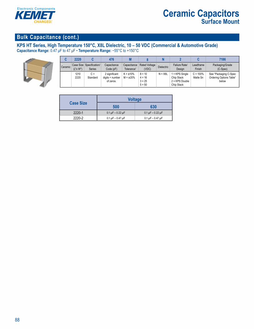
88
Ceramic CapacitorsSurface Mount
Bulk Capacitance (cont.)KPS HT Series, High Temperature 150°C, X8L Dielectric, 10 – 50 VDC (Commercial & Automotive Grade)Capacitance Range: 0.47 μF to 47 μF • Temperature Range: −55°C to +150°C
Order ng Information
C 2220 C 476 M 8 N 2 C 7186
Ceramic Case Size (L"x W")
Specifi cation/Series
CapacitanceCode (pF)
CapacitanceTolerance1
Rated Voltage (VDC) Dielectric Failure Rate/
DesignLeadframe
FinishPackaging/Grade
(C-Spec)12102220
C = Standard
2 signifi cant digits + number
of zeros.
K = ±10%M = ±20%
8 = 104 = 163 = 255 = 50
N = X8L 1 = KPS Single Chip Stack2 = KPS Double Chip Stack
C = 100% Matte Sn
See “Packaging C-Spec Ordering Options Table”
below
Case SizeVoltage
500 6302220-1 0.1 µF – 0.22 µF 0.1 µF – 0.22 µF
2220-2 0.1 µF – 0.47 µF 0.1 µF – 0.47 µF

89
Ceramic CapacitorsSurface Mount
Bulk Capacitance (cont.) KPS MIL Series, SMPS Stacked Capacitors, 25 – 1,000 VDC (Commercial, Military, & Space Grades)Capacitance Range: 0.047 μF to 75 μF • Temperature Rang : −55°C to +125°C
er o 1 Please refer to perfor anc
(Do not use his ordering co e if a P MIL SPE pa t type is requir d Please ord r usin MIL–SPEC o re arding M L–PRF–49470 QPL order ng i orm t on i
L1 R N 30 C 106 K S 12
Product Family1Dielectric
Classifi cation/ Characteristic2
LeadConfi guration3
Case Size/ Case Code
(CC)
Rated Voltage (VDC)
CapacitanceCode (pF)
CapacitanceTolerance Testing Option4 Maximum Height
Dimension (in.)5
L1 = UnencapsulatedL2 = Encapsulated
Q = BQ R = BRX = BXW = X7R
N = StraightL = Formed "L" M = Formed "L" J = Formed "J" K = Formed "J"
30 = CC 340 = CC 450 = CC 5
3 = 255 = 501 = 1002 = 200C = 500B = 630D = 1,000
Two signifi cant
digits + number of
zeros
J = ±5%K = ±10%M = ±20%
B = M49470 "B" LevelT = M49470 "T" LevelC = DSCC87106S = CommercialX = Non-Standard (Customer Specifi c Requirements)
Unencapsulated12 = 0.12"24 = 0.24"36 = 0.36"48 = 0.48"65 = 0.65"
Encapsulated27 = 0.27"39 = 0.39"53 = 0.53"66 = 0.66"80 = 0.80"
MIL–PRF 49470, DSCC 87106
d p St k d C p ci
MI –PRF–49470 rdering Inform
M49470 R 01 474 K C NPerformance Specifi cation
Indicating MIL–PRF–494701Dielectric Classifi cation/
Characteristic2Performance Specifi cation Sheet
Number (Indicating MIL–PRF–49470/1)3CapacitanceCode (pF)
CapacitanceTolerance
Rated Voltage (VDC)
LeadConfi guration4
M49470 = B level T49470 = T levelA “T” prefi x is used in place of the “M” for T level product.
Q = BQ R = BRX = BX
01 = Unencapsulated02 = Encapsulated
Two signifi cant
digits + number of
zeros
J = ±5%K = ±10%M = ±20%
A = 50B = 100C = 200E = 500
N = Straight PinL = Formed "L" M = Formed "L" J = Formed "J" K = Formed "J"
BQ
Case SizeVoltage
200 5003 2.4 µF – 27 µF 2.2 µF – 5.6 µF
4 0.82 µF – 10 µF 0.82 µF – 1.8 µF
5 0.33 µF – 3.3 µF 0.15 µF – 0.68 µF
BR
Case SizeVoltage
100 2003 5.6 µF – 50 µF 4.7 µF – 12 µF
4 1 5 µF – 18 µF 1.8 µF – 3.9 µF
5 0 56 µF – 6 µF 0.47 µF – 1 5 µF
BX
Case SizeVoltage
25 50 1003 6.8 µF – 75 µF 6.8 µF – 75 µF 10 µF – 27 µF
4 2.2 µF – 24 µF 2.2 µF – 24 µF 3 9 µF – 8.2 µF
5 0.82 µF – 7.5 µF 0.82 µF – 7.5 µF 0.68 µF – 3.3 µF
X7R
Case SizeVoltage
500 630 1,0003 1 µF – 12 µF 0.22 µF – 6.8 µF 0.1 µF – 3.3 µF
4 0.39 µF – 3.9 µF 0.1 µF – 2 2 µF 0.1 µF – 1 µF
5 0.12 µF – 1 5 µF 6.8 nF – 0.75 µF 4.7 nF – 0.39 µF

90
Ceramic CapacitorsSurface Mount
High Temperature (> 125ºC) High Temperature 150°C, Ultra-Stable X8R Dielectric, 25 – 100 VDC (Commercial & Automotive Grade)Capacitance Range: 100 pF to 0.22 μF T mpe ature Range: −55°C to +150°C
Ordering nformation
C 1210 C 184 K 3 H A C AUTO
Ce amic Case Size (L" x W")
Specifi cation/Series1
Capacitance Code (pF)
Capacitance Tolerance
Rated Voltage (VDC) Dielectric Failure Rate/
Design Termination Finish2 Packaging/Grade (C-Spec)
040206030805120612101812
C = Standard 2 signifi cant digits + number
of zeros
F = ±1%G = ±2%J = ±5%K = ±10%M = ±20%
3 = 255 = 501 = 100
H = Ultra Stable X8R
A = N/A C = 100% Matte SnL = SnPb (5% Pb min mum)
See “Packaging C-Spec Ordering Options Table”
below
Case SizeVoltage
25 50 1000402 100 pF – 1 5 nF 100 pF – 1 5 nF 100 pF – 1 nF
0603 430 pF – 0.01 µF 430 pF – 6.8 nF 430 pF – 4.7 nF
0805 2 nF – 0.0 3 µF 2 nF 0 022 µF 2 nF – 0.015 µF
1206 6.8 nF – 0.1 µF 6.8 nF – 0.082 µF 6.8 nF – 0.056 µF
1210 0.012 µF – 0.18 µF 0.012 µF – 0.15 µF 0.012 µF – 0.1 µF
1812 0.015 µF – 0.22 µF 0.015 µF – 0.15 µF
High Temperature 150°C, X8L Dielectric, 10 – 50 VDC (Commercial & Automotive Grade)Capacitance Range: 0.012 μF to 10 μF Temperature Range: −55°C to +150°C
Over iew
KEMET’s X8L dielec c featu es a 150°C aximum ope ating tempe ature nd is considered general purpo e high
a suite by d
stability c ci e ti r iti
e an i a ch ge in c pacitanc t
o am p to 12 Beyond C s a a itan
m t
loped for c
licati s he t hi pe
s we igh m e l ti s ned w cks e u t n fr ssive tens e
ar str ced uring bo xure and therm e av i a le w MET s ex ble tion t c t d
stress o the r gid ceram c body, th refore mit
h a ro t eme
fl perform e ard termination
dd tion o r e, automoti ade devices demand ect o
– 50 VDC
Ordering nformation
C 1210 X 106 K 8 N A C TU
Ceramic Case Size (L" x W")
Specifi cation/Series1
Capacitance Code (pF)
Capacitance Tolerance
Rated Voltage (VDC) Dielectric Failure Rate/
Design Termination Finish2 Packaging/Grade (C-Spec)
04020603080512061210
C = StandardX = Flexible Termination
2 signifi cant digits +
number of zeros
J = ±5%K = ±10%M = ±20%
8 = 103 = 255 = 50
N = X8L A = N/A C = 100% Matte SnL = SnPb (5% Pb minimum)
See "Packaging C-Spec Ordering Options Table"
below
Case SizeVoltage
10 16 25 500402 0.012 µF – 0.047 µF 0.012 µF – 0.022 µF
0603 0.047 µF – 0.22 µF 0.047 µF – 0.15 µF 0.047 µF
0805 0.15 µF – 1 µF 0.82 µF – 1 µF 0.15 µF – 0.68 µF 0.15 µF – 0 22 µF
1206 0.47 µF – 4.7 µF 2.7 µF – 4.7 µF 0.47 µF – 2 2 µF 0.47 µF
1210 0 39 µF – 10 µF 5.6 µF – 10 µF 0 39 µF – 4.7 µF 0.39 µF – 1 µF
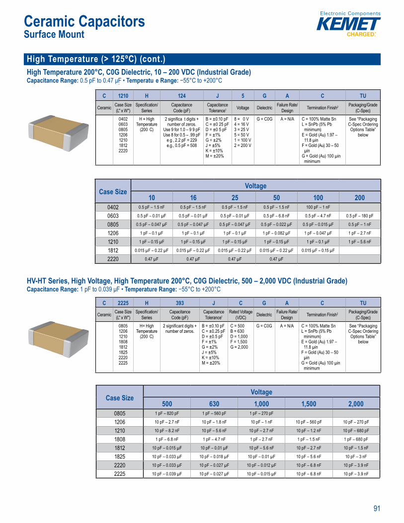
91
Ceramic CapacitorsSurface Mount
High Temperature (> 125ºC) (cont.)High Temperature 200°C, C0G Dielectric, 10 – 200 VDC (Industrial Grade)Capacitance Range: 0.5 pF to 0.47 μF • Temperatu e Range: −55°C to +200°C
Ord ri g I formation
C 1210 H 124 J 5 G A C TU
Ceramic Case Size (L" x W")
Specifi cation/Series
Capacitance Code (pF)
Capacitance Tolerance1 Voltage Dielectric Failure Rate/
Design Termination Finish2 Packaging/Grade (C-Spec)
0402060308051206121018122220
H = High Temperature
(200 C)
2 signifi ca t digits +number of zeros.
Use 9 for 1.0 – 9 9 pFUse 8 for 0.5 – .99 pF
e g , 2.2 pF = 229e.g., 0.5 pF = 508
B = ±0.10 pFC = ±0 25 pFD = ±0 5 pFF = ±1%G = ±2%J = ±5%K = ±10%M = ±20%
8 = 0 V4 = 16 V3 = 25 V5 = 50 V1 = 100 V2 = 200 V
G = C0G A = N/A C = 100% Matte SnL = SnPb (5% Pb
minimum)E = Gold (Au) 1.97 –
11.8 µinF = Gold (Au) 30 – 50
µinG = Gold (Au) 100 µin
minimum
See “Packaging C-Spec Ordering
Options Table” below
Case SizeVoltage
10 16 25 50 100 2000402 0.5 pF – 1.5 nF 0.5 pF – 1.5 nF 0.5 pF – 1.5 nF 0.5 pF – 1.5 nF 100 pF – 1 nF
0603 0.5 pF – 0.01 µF 0.5 pF – 0.01 µF 0.5 pF – 0.01 µF 0.5 pF – 6.8 nF 0.5 pF – 4.7 nF 0.5 pF – 180 pF
0805 0.5 pF – 0.047 µF 0.5 pF – 0.047 µF 0.5 pF – 0.047 µF 0.5 pF – 0.022 µF 0.5 pF – 0.015 µF 0.5 pF – 1 nF
1206 1 pF – 0.1 µF 1 pF – 0.1 µF 1 pF – 0.1 µF 1 pF – 0.082 µF 1 pF – 0.047 µF 1 pF – 2.7 nF
1210 1 pF – 0.15 µF 1 pF – 0.15 µF 1 pF – 0.15 µF 1 pF – 0.15 µF 1 pF – 0.1 µF 1 pF – 5.6 nF
1812 0.015 µF – 0.22 µF 0.015 µF – 0.22 µF 0.015 µF – 0.22 µF 0.015 µF – 0.22 µF 0.015 µF – 0.15 µF
2220 0.47 µF 0.47 µF 0.47 µF 0.47 µF
HV-HT Series, High Voltage, High Temperature 200°C, C0G Dielectric, 500 – 2,000 VDC (Industrial Grade)Capacitance Range: 1 pF to 0.039 μF • Temperature Range: −55°C to +200°C
Order ng Information
C 2225 H 393 J C G A C TU
Ceramic Case Size (L" x W")
Specifi cation/Series
Capacitance Code (pF)
Capacitance Tolerance1
Rated Voltage(VDC) Dielectric Failure Rate/
Design Termination Finish2 Packaging/Grade (C-Spec)
08051206121018081812182522202225
H= High Temperature
(200 C)
2 signifi cant digits +number of zeros.
B = ±0.10 pFC = ±0.25 pFD = ±0.5 pFF = ±1%G = ±2%J = ±5%K = ±10%M = ±20%
C = 500B = 630D = 1,000F = 1,500G = 2,000
G = C0G A = N/A C = 100% Matte SnL = SnPb (5% Pb
minimum)E = Gold (Au) 1.97 –
11.8 µinF = Gold (Au) 30 – 50
µinG = Gold (Au) 100 µin
minimum
See “Packaging C-Spec Ordering
Options Table” below
Ov r ie
fa nt C t a
ed of a r bust and pr ary base m ectrode le tri m th dustry le rforman
tem ures Th surface mountab devices ºC im m o i g temper ture d re
des d the dem ds of ars v r l ex orat on a u omotiv
gine t er an e
LC ure e su s nant rcui a i ns or t o e
sta a it ce cha st cs equ e g i a t i r ct o
i
o /ºC 5 n a x ig s tion resist o d s p n factor at
es up ow ESR t i req enc and of s p rior volumet ciency over
c p ec o s a d ( ME) and ba e ie ectric system
hes Fr e RoHS d p ions.
S il
Case SizeVoltage
500 630 1,000 1,500 2,0000805 1 pF – 820 pF 1 pF – 560 pF 1 pF – 270 pF
1206 10 pF – 2.7 nF 10 pF – 1.8 nF 10 pF – 1 nF 10 pF – 560 pF 10 pF – 270 pF
1210 10 pF – 8.2 nF 10 pF – 5.6 nF 10 pF – 2.7 nF 10 pF – 1.2 nF 10 pF – 680 pF
1808 1 pF – 6.8 nF 1 pF – 4.7 nF 1 pF – 2.7 nF 1 pF – 1.5 nF 1 pF – 680 pF
1812 10 pF – 0.015 µF 10 pF – 0.01 µF 10 pF – 5.6 nF 10 pF – 2.7 nF 10 pF – 1.5 nF
1825 10 pF – 0.033 µF 10 pF – 0.018 µF 10 pF – 0.01 µF 10 pF – 5.6 nF 10 pF – 3 nF
2220 10 pF – 0.033 µF 10 pF – 0.027 µF 10 pF – 0.012 µF 10 pF – 6.8 nF 10 pF – 3.9 nF
2225 10 pF – 0.039 µF 10 pF – 0.027 µF 10 pF – 0.015 µF 10 pF – 6.8 nF 10 pF – 3.9 nF

92
Ceramic CapacitorsSurface Mount
High Temperature (> 125ºC) (cont.)Flexible Termination System (FT-CAP), Ultra-Stable X8R Dielectric, 25 – 100 VDC (Commercial & Automotive Grade)Capacitance Range: 430 pF to 0 22 μF Temperature Range: −55°C to +150°C
O dering fo matio
C 1206 X 104 J 3 H A C AUTO
Ceramic Case Size (L" x W")
Specifi cation/Series
Capacitance Code (pF)
Capacitance Tolerance
Reated Voltage (VDC) Dielectric Failure Rate/
DesignTermination
Finish1Packaging/Grade
(C-Spec)06030805120612101812
X = Flexible Termination
2 signifi cant digits +
number of zeros.
F = ±1%G = ±2%J = ±5%K = ±10%M = ±20%
3 = 255 = 501 = 100
H = Ultra-Stable X8R
A = N/A C = 100% Matte SnL = SnPb (5% Pb minimum)
See "Packaging
C-Spec Ordering
Options Table" below
Case SizeVoltage
25 50 1000603 430 pF – 0.01 µF 430 pF – 6.8 nF 430 pF – 4.7 nF
0805 2 nF – 0.033 µF 2 nF – 0.022 µF 2 nF – 0.015 µF
1206 6.8 nF – 0.1 µF 6.8 nF – 0.082 µF 6.8 nF – 0.056 µF
1210 0.012 µF – 0.18 µF 0.012 µF – 0.15 µF 0.012 µF – 0.1 µF
1812 0.015 µF – 0.22 µF 0.015 µF – 0.15 µF
High Temperature 175ºC, X7R Dielectric, 16 – 200 VDC (Industrial Grade)Capacitance Range: 2.7 nF to 3.3 µF • Temperature Range: −55°C to +175°C
verv ew
igh erature X ielectr paci ors and me tem ture p s
f me ele
R dielectri
acitors are w que circ
Q and capac t nce ch isti s re not hey e ic e c a ac a ce i
S r a Mou Mu i ayer Cera
High T mper ture 175ºC, X7R Dielec ric 16 – 200 VDCI u t i l G )
Ord rin nformation
C 1210 R 225 K 3 R A C T050
Ceramic Case Size1 (L" x W")
Specifi cation/Series1
Capacitance Code (pF)
Capacitance Tolerance
Rated Voltage (VDC) Dielectric Failure Rate/
DesignTermination
Finish Packaging/Grade (C-Spec)2
040206030805120612101812
G = 175 C with standard terminationR = 175 C w/ Flexible Termination
First two digits represent signifi cant
fi gures. Third digit specifi es
number of zeros.
J = ±5%K = ±10%M = ±20%
4 = 163 = 25 5 = 501 = 100 2 = 200
R = X7R A = N/A C = 100% Matte Sn
Blank = Bulk7292 = Waffl e Pack/TrayTU = 7" Reel - Unmarked (full reel quantity)T050 = 50 pieces/7" Reel - UnmarkedT100 = 100 pieces/7" Reel - UnmarkedT250 = 250 pieces/7" Reel - UnmarkedT500 = 500 pieces/7" Reel - UnmarkedT1K0 = 1,000 pieces/Reel - Unmarked
Case SizeVoltage
16 25 50 2000402 2.7 nF – 0.047 µF 2.7 nF – 0.022 µF 2.7 nF – 0.01 µF
0603 0.018 µF – 0.15 µF 0.018 µF – 0.1 µF
0805 0.047 µF – 0.68 µF 0.047 µF – 0 27 µF
1206 0.1 µF – 1 µF 0.1 µF – 0.47 µF
1210 0.18 µF – 2.2 µF 0.18 µF – 1 µF
1812 0 22 µF – 3.3 µF 0 22 µF – 1 5 µF 0.056 µF – 0.1 µF
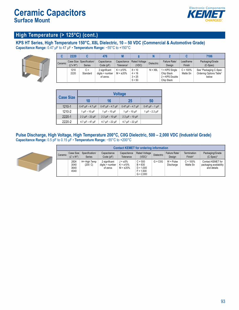
93
Ceramic CapacitorsSurface Mount
High Temperature (> 125ºC) (cont.)KPS HT Series, High Temperature 150°C, X8L Dielectric, 10 – 50 VDC (Commercial & Automotive Grade)Capacitance Range: 0.47 μF to 47 μF • Temperature Range: −55°C to +150°C
Order ng Information
C 2220 C 476 M 8 N 2 C 7186
Ceramic Case Size (L"x W")
Specifi cation/Series
CapacitanceCode (pF)
CapacitanceTolerance1
Rated Voltage (VDC) Dielectric Failure Rate/
DesignLeadframe
FinishPackaging/Grade
(C-Spec)12102220
C = Standard
2 signifi cant digits + number
of zeros.
K = ±10%M = ±20%
8 = 104 = 163 = 255 = 50
N = X8L 1 = KPS Single Chip Stack2 = KPS Double Chip Stack
C = 100% Matte Sn
See “Packaging C-Spec Ordering Options Table”
below
C p ci anc ering
• Available capac t nce s up t d
Case SizeVoltage
10 16 25 501210-1 0.47 µF – 4.7 µF 0.47 µF – 4.7 µF 0.47 µF – 4.7 µF 0.47 µF – 1 µF
1210-2 1 µF – 10 µF 1 µF – 10 µF 1 µF – 10 µF 1 µF – 2.2 µF
2220-1 2 2 µF – 22 µF 2 2 µF – 10 µF 2 2 µF – 10 µF
2220-2 4.7 µF – 47 µF 4.7 µF – 22 µF 4.7 µF – 22 µF
Pulse Discharge, High Voltage, High Temperature 200°C, C0G Dielectric, 500 – 2,000 VDC (Industrial Grade)Capacitance Range: 0.5 pF to 0.15 μF • Temperature Range: −55°C to +200°C
rd i g I formation
Contact KEMET for ordering information
Ceramic Case Size (L" x W")
Specifi cation/Series
Capacitance Code (pF)
Capacitance Tolerance
Rated Voltage(VDC)1 Dielectric Failure Rate/
DesignTermination
Finish2
Packaging/Grade (C-Spec)3
2824304036404540
H= High Temp (200 C)
2 signifi cant digits + number
of zeros
J = ±5%K = ±10%M = ±20%
C = 500B = 630D = 1,000F = 1,500G = 2,000
G = C0G W = Pulse Discharge
C = 100% Matte Sn
Contact KEMET for packaging availability
and details
g L b) nt B t l t y g y i i ti l cit ng ng n 0 F μF a lab e ance ole an o ±5 ±10 20% xt eme y SR an ESL
KEME s ndustrial Gra mo nt capacit rs n C0
( ) ielect ic s s e , e e p rf c tiv t a itan Pulse D scharge apacitor avera e greate tha 0% her b e o lt c et ous me l e ectr d
i i n i
evices f t e a 0°C ti pe t
( )
high insulation res s a ce with low dissipation facto
s P a m e
f es and f l h, hig g
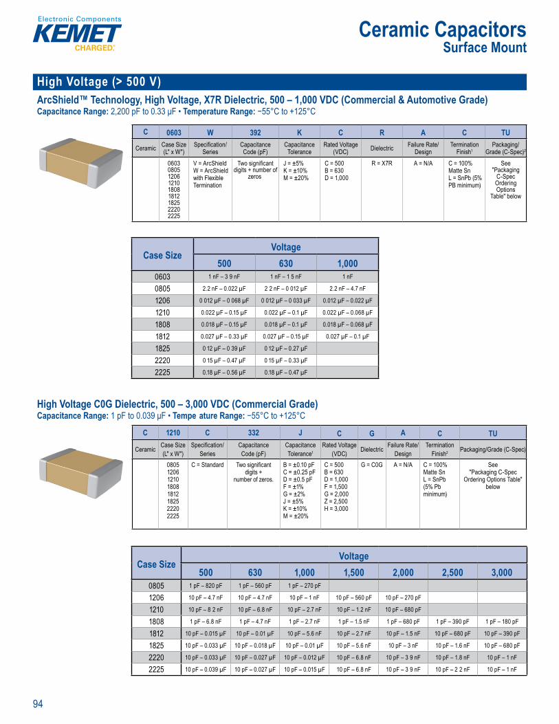
94
Ceramic CapacitorsSurface Mount
High Voltage (> 500 V) ArcShield™ Technology, High Voltage, X7R Dielectric, 500 – 1,000 VDC (Commercial & Automotive Grade)Capacitance Range: 2,200 pF to 0.33 μF • Temperature Range: −55°C to +125°C
an a i ab
Order ng Inf rmation
C 0603 W 392 K C R A C TU
Ceramic Case Size (L" x W")
Specifi cation/Series
Capacitance Code (pF)
Capacitance Tolerance
Rated Voltage (VDC) Dielectric Failure Rate/
DesignTermination
Finish1Packaging/
Grade (C-Spec)2
060308051206121018081812182522202225
V = ArcShieldW = ArcShield with Flexible Termination
Two signifi cant digits + number of
zeros
J = ±5%K = ±10%M = ±20%
C = 500 B = 630 D = 1,000
R = X7R A = N/A C = 100% Matte SnL = SnPb (5% PB minimum)
See "Packaging
C-Spec Ordering Options
Table" below
Case SizeVoltage
500 630 1,0000603 1 nF – 3 9 nF 1 nF – 1 5 nF 1 nF
0805 2.2 nF – 0.022 µF 2 2 nF – 0 012 µF 2.2 nF – 4.7 nF
1206 0 012 µF – 0 068 µF 0 012 µF – 0 033 µF 0.012 µF – 0.022 µF
1210 0.022 µF – 0.15 µF 0.022 µF – 0.1 µF 0.022 µF – 0.068 µF
1808 0.018 µF – 0.15 µF 0.018 µF – 0.1 µF 0.018 µF – 0.068 µF
1812 0.027 µF – 0.33 µF 0.027 µF – 0.15 µF 0.027 µF – 0.1 µF
1825 0 12 µF – 0 39 µF 0 12 µF – 0.27 µF
2220 0 15 µF – 0.47 µF 0 15 µF – 0.33 µF
2225 0.18 µF – 0.56 µF 0.18 µF – 0.47 µF
High Voltage C0G Dielectric, 500 – 3,000 VDC (Commercial Grade)Capacitance Range: 1 pF to 0.039 μF • Tempe ature Range: −55°C to +125°C
Order n InformationC 1210 C 332 J C G A C TU
Ceramic Case Size (L" x W")
Specifi cation/Series
Capacitance Code (pF)
Capacitance Tolerance1
Rated Voltage (VDC) Dielectric Failure Rate/
DesignTermination
Finish2 Packaging/Grade (C-Spec)
08051206121018081812182522202225
C = Standard Two signifi cant digits +
number of zeros.
B = ±0.10 pFC = ±0.25 pFD = ±0.5 pFF = ±1%G = ±2%J = ±5%K = ±10%M = ±20%
C = 500 B = 630 D = 1,000 F = 1,500 G = 2,000 Z = 2,500 H = 3,000
G = C0G A = N/A C = 100% Matte SnL = SnPb (5% Pb minimum)
See"Packaging C-Spec
Ordering Options Table" below
igh
MET High Vo e surface nt MLCCs 0G t t
side “s ble ” The lect onics In u tr s A) c cter zes C ctric ass I mpo s of this c
g a e e
C0
om -55°C
5°C
device ESR t h cie d fi tional bbers o fi lter p icat ons such
hing pp es a d lightin l ast . T eir o a p e a g e e has ma e hig r c ic o e g
i t r i y i e
motiv ecom n ca me ic l m l t ace s tor a est/d stic eq ipment
In additio Comme Grade Au ot e Gra vices v t E t
o 2 0 c t n e e s
Case SizeVoltage
500 630 1,000 1,500 2,000 2,500 3,0000805 1 pF – 820 pF 1 pF – 560 pF 1 pF – 270 pF
1206 10 pF – 4.7 nF 10 pF – 4.7 nF 10 pF – 1 nF 10 pF – 560 pF 10 pF – 270 pF
1210 10 pF – 8 2 nF 10 pF – 6.8 nF 10 pF – 2.7 nF 10 pF – 1.2 nF 10 pF – 680 pF
1808 1 pF – 6.8 nF 1 pF – 4.7 nF 1 pF – 2.7 nF 1 pF – 1.5 nF 1 pF – 680 pF 1 pF – 390 pF 1 pF – 180 pF
1812 10 pF – 0.015 µF 10 pF – 0.01 µF 10 pF – 5.6 nF 10 pF – 2.7 nF 10 pF – 1.5 nF 10 pF – 680 pF 10 pF – 390 pF
1825 10 pF – 0.033 µF 10 pF – 0.018 µF 10 pF – 0.01 µF 10 pF – 5.6 nF 10 pF – 3 nF 10 pF – 1.6 nF 10 pF – 680 pF
2220 10 pF – 0.033 µF 10 pF – 0.027 µF 10 pF – 0.012 µF 10 pF – 6.8 nF 10 pF – 3 9 nF 10 pF – 1.8 nF 10 pF – 1 nF
2225 10 pF – 0.039 µF 10 pF – 0.027 µF 10 pF – 0.015 µF 10 pF – 6.8 nF 10 pF – 3 9 nF 10 pF – 2 2 nF 10 pF – 1 nF
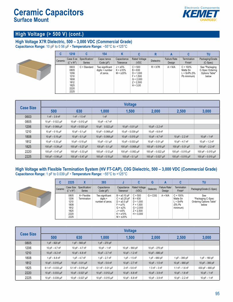
95
Ceramic CapacitorsSurface Mount
High Voltage (> 500 V) (cont.)High Voltage X7R Dielectric, 500 – 3,000 VDC (Commercial Grade)Capacitance Range: 10 pF to 0 56 μF • Temperature Range: −55°C to +125°C
the pre erred diel ctric n addi ion t t ei u e i
ing nf r a i
C 1210 C 154 K C R A C TU
Ceramic Case S ze (L" x W")
Specifi cation/Series
Capac tance Code (pF)
Capacitance Tolerance
Rated Voltage (VDC Dielectric Failure Rate
DesignTermination
Finish1Packaging/Grade
(C-Spec)060308051206121018081812182522202225
C = Standard Two signifi cant digits + number
of zeros.
J = ±5%K = ±10%M = ±20%
C = 500 B = 630 D = 1,000 F = 1,500 G = 2,000 Z = 2,500 H = 3,00
R = X7R A = N/A C = 100% Matte SnL = SnPb (5% Pb minimum)
See "Packaging C-Spec Ordering Options Table"
below
Case SizeVoltage
500 630 1,000 1,500 2,000 2,500 3,0000603 1 nF – 3.9 nF 1 nF – 1 5 nF 1 nF
0805 10 pF – 0 022 µF 10 pF – 0.012 µF 10 pF – 4.7 nF
1206 10 pF – 0 068 µF 10 pF – 0 033 µF 10 pF 0.022 µF 10 pF – 0.01 µF 10 pF – 2.2 nF
1210 10 pF – 0 15 µF 10 pF – 0.1 µF 10 pF – 0.068 µF 10 pF – 0.039 µF 10 pF – 6.8 nF
1808 10 pF – 0.15 µF 10 pF – 0.1 µF 10 pF – 0.068 µF 10 pF – 0.015 µF 10 pF – 4.7 nF 10 pF – 2.2 nF 10 pF – 1 nF
1812 10 pF – 0.33 µF 10 pF – 0.15 µF 10 pF – 0.1 µF 10 pF – 0.033 µF 10 pF – 0.01 µF 10 pF – 4.7 nF 10 pF – 1.2 nF
1825 100 pF – 0.39 µF 100 pF – 0.27 µF 100 pF – 0.1 µF 100 pF – 0.068 µF 100 pF – 0.015 µF 100 pF – 0.01 µF 100 pF – 2.2 nF
2220 100 pF – 0 47 µF 100 pF – 0.33 µF 100 pF – 0.12 µF 100 pF – 0.082 µF 100 pF – 0.022 µF 100 pF – 0.015 µF 100 pF – 0.015 µF
2225 100 pF – 0.56 µF 100 pF – 0.47 µF 100 pF – 0.15 µF 100 pF – 0.1 µF 100 pF – 0.027 µF 100 pF – 0.015 µF 100 pF – 0.015 µF
High Voltage with Flexible Termination System (HV FT-CAP), C0G Dielectric, 500 – 3,000 VDC (Commercial Grade)Capacitance Range: 1 pF to 0.039 μF • Temperature Range: −55°C to +125°C
Order ng Information
C 2225 X 393 J C G A C TU
Ceramic Case Size (L" x W")
Specifi cation/Series
Capacitance Code (pF)
Capacitance Tolerance1
Rated Voltage (VDC) Dielectric Failure Rate/
DesignTermination
Finish2 Packaging/Grade (C-Spec)
08051206121018081812182522202225
X= Flexible Termination
Two signifi cant digits +
number of zeros.
B = ±0.10 pFC = ±0.25 pFD = ±0.5 pFF = ±1%G = ±2%J = ±5%K = ±10%M = ±20%
C = 500B = 630D = 1,000F = 1,500G = 2,000Z = 2,500H = 3,000
G = C0G A = N/A C = 100% Matte SnL = SnPb (5% Pb minimum)
See“Packaging C-Spec
Ordering Options Table” below
1
Overv ew
ME gh V th in -C unt MLCCs in C0G di ctric addres e pr mary
e o ML – fl ex c which are lly the re tens shear st ses produce i g bo
he g seve a f i est n e
e nd
of th i
t e
en d han does ri r
E v rf t L i fea ur °C max m m o g temp rat re er th most tage and te e perfo mance e am c ie ec ials. G (N e tric ca a to bi o
c g a o g
i t C r °
T e S ue conven a bbers or fi l in applicat such as swit and l g lasts ptional pe e h ue cies m e hig ge MLCC’s the pre n i eers or de. addition to t apacitors ar used i m li
C0 D r c
Case SizeVoltage
500 630 1,000 1,500 2,000 2,500 3,0000805 1 pF – 820 pF 1 pF – 560 pF 1 pF – 270 pF
1206 10 pF – 4.7 nF 10 pF – 4.7 nF 10 pF – 1 nF 10 pF – 560 pF 10 pF – 270 pF
1210 10 pF – 8.2 nF 10 pF – 6.8 nF 10 pF – 2.7 nF 10 pF – 1.2 nF 10 pF – 680 pF
1808 1 pF – 6.8 nF 1 pF – 4.7 nF 1 pF – 2.7 nF 1 pF – 1 5 nF 1 pF – 680 pF 1 pF – 390 pF 1 pF – 180 pF
1812 10 pF – 0.015 µF 10 pF – 0.01 µF 10 pF – 5.6 nF 10 pF – 2.7 nF 10 pF – 1.5 nF 10 pF – 680 pF 10 pF – 390 pF
1825 9.1 nF – 0.033 µF 5.1 nF – 0.018 µF 5.1 nF – 0.01 µF 2 nF – 5.6 nF 1 3 nF – 3 nF 1.1 nF – 1.6 nF 430 pF – 680 pF
2220 10 pF – 0.033 µF 10 pF – 0.027 µF 10 pF – 0.012 µF 10 pF – 6.8 nF 10 pF – 3.9 nF 10 pF – 1.8 nF 10 pF – 1 nF
2225 10 pF – 0.039 µF 10 pF – 0.027 µF 10 pF – 0.015 µF 10 pF – 6.8 nF 10 pF – 3.9 nF 10 pF – 2.2 nF 10 pF – 1 nF

96
Ceramic CapacitorsSurface Mount
High Voltage (> 500 V) (cont.)High Voltage with Flexible Termination System (HV FT-CAP) X7R Dielectric, 500 – 3,000 VDC (Commercial Grade)Capacitance Range: 10 pF to 0 56 μF Tempe ature Range: −55°C to +125°C
O er n nformation
C 1210 X 154 K C R A C TU
Ceramic Case Size (L" x W")
Specifi cation/Series
Capacitance Code (pF)
Capacitance Tolerance
Rated Voltage (VDC) Dielectric Failure Rate/
DesignTermination
FinishPackaging/Grade
(C-Spec)060308051206121018081812182522202225
X = Flexible Termination
Two signifi cant digits + number
of zeros.
J = ±5%K = ±10%M = ±20%
C = 500 B = 630 D = 1,000 F = 1,500 G = 2,000 Z = 2,500 H = 3,000
R = X7R A = N/A C = 100% Matte SnL = SnPb (5% Pb minimum)
See "Packaging C-Spec Ordering Options Table"
below
Case SizeVoltage
500 630 1,000 1,500 2,000 2,500 3,0000603 1 nF – 3.9 nF 1 nF – 1 5 nF 1 nF
0805 10 pF – 0.022 µF 10 pF – 0.012 µF 10 pF – 5.6 nF
1206 10 pF – 0.068 µF 10 pF – 0.033 µF 10 pF – 0.022 µF 10 pF – 0.01 µF 10 pF – 2.2 nF
1210 10 pF – 0.15 µF 10 pF – 0.1 µF 10 pF – 0.068 µF 10 pF – 0.039 µF 10 pF – 6.8 nF
1808 10 pF – 0.15 µF 10 pF – 0 1 µF 10 pF – 0.068 µF 10 pF – 0.015 µF 10 pF – 4.7 nF 10 pF – 2.2 nF 10 pF – 1 nF
1812 51 pF – 0 33 µF 51 pF 0.15 µF 51 pF – 0.1 µF 51 pF – 0.033 µF 51 pF – 0.01 µF 51 pF – 4.7 nF 51 pF – 1.2 nF
1825 470 pF – 0.39 µF 470 pF – 0.27 µF 470 pF – 0.1 µF 470 pF – 0.068 µF 470 pF – 0.015 µF 470 pF – 0.01 µF 470 pF – 3 3 nF
2220 470 pF – 0.47 µF 470 pF – 0.33 µF 470 pF – 0.12 µF 470 pF – 0.082 µF 470 pF – 0.022 µF 470 pF – 0.015 µF 470 pF – 0.015 µF
2225 680 pF – 0.56 µF 680 pF – 0.47 µF 680 pF – 0.15 µF 680 pF – 0.1 µF 680 pF – 0.027 µF 680 pF – 0.015 µF 680 pF – 0.015 µF
KPS Series, High Voltage, X7R Dielectric, 500 – 630 VDC (Commercial Grade)Capacitance Range: 0.047 μF to 1.0 μF • Temperature Range: −55°C to +125°C
Bene
ob t ter s st
• EI ase ize• DC e ratin s of 0 630 V• Cap ce offer ngs ra om 0 04 µF .0 µF a p ci e tol o ± %
O v
KEMET Powe Solutions (KPS) H gh Voltag stack d
ic ck o o e am a le comp ct surface m nt package e attached
mecha ly sol capacit om the u t bo th reby o ng advance echanic
stre formanc so ation also d es es au
e is nce
a ed
vo o a ca ef o amb e Capacita change i ited to ±15%
from hese are c b-Free re les and de ow SR ES a her ripple c o other d c solutions
o uc
e
y semico d test/di pment
Order ng I ormation
C 2220 C 105 M C R 2 C 7186
Ceramic Case Size (L"x W")
Specifi cation/Series
CapacitanceCode (pF)
CapacitanceTolerance1
Rated Voltage(VDC) Dielectric Failure Rate/
DesignLeadframe
Finish2Packaging/Grade
(C-Spec)2220 C =
Standard2 signifi cant digits +
number of zeros.K = ±10%M = ±20%
C = 500B = 630
R = X7R 1 = KPS Single Chip Stack2 = KPS Double Chip Stack
C = 100% Matte Sn
See “Packaging C-Spec Ordering
Options Table” below
Case SizeVoltage
500 6302220-1 0.047 µF – 0.47 µF 0.047 µF – 0.22 µF
2220-2 0.1 µF – 1 µF 0.1 µF – 0.47 µF
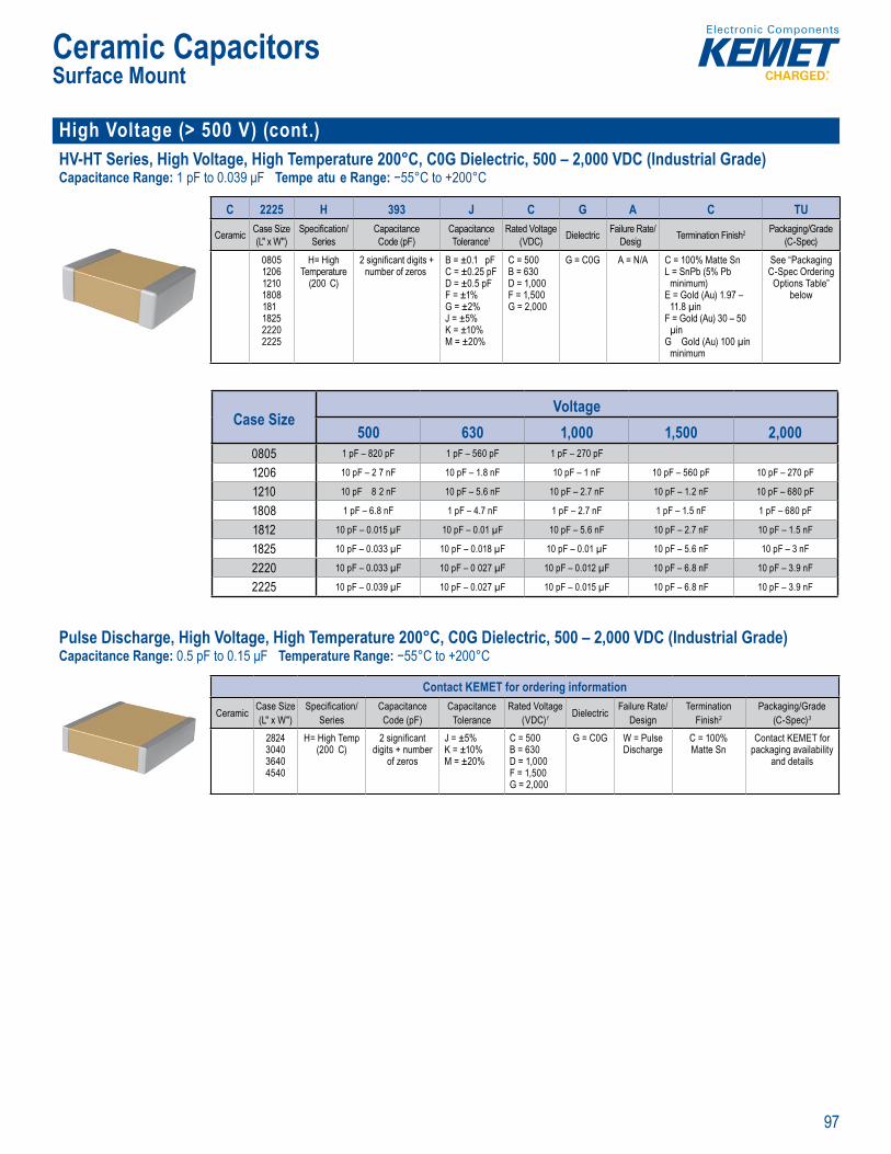
97
Ceramic CapacitorsSurface Mount
High Voltage (> 500 V) (cont.)HV-HT Series, High Voltage, High Temperature 200°C, C0G Dielectric, 500 – 2,000 VDC (Industrial Grade)Capacitance Range: 1 pF to 0.039 μF Tempe atu e Range: −55°C to +200°C
Order n Information
C 2225 H 393 J C G A C TU
Ceramic Case Size (L" x W")
Specifi cation/Series
Capacitance Code (pF)
Capacitance Tolerance1
Rated Voltage(VDC) Dielectric Failure Rate/
Desig Termination Finish2 Packaging/Grade (C-Spec)
0805120612101808181182522202225
H= High Temperature
(200 C)
2 signifi cant digits +number of zeros
B = ±0.1 pFC = ±0.25 pFD = ±0.5 pFF = ±1%G = ±2%J = ±5%K = ±10%M = ±20%
C = 500B = 630D = 1,000F = 1,500G = 2,000
G = C0G A = N/A C = 100% Matte SnL = SnPb (5% Pb
minimum)E = Gold (Au) 1.97 –
11.8 µinF = Gold (Au) 30 – 50
µinG Gold (Au) 100 µin
minimum
See “Packaging C-Spec Ordering
Options Table” below
and vo tage and boast a
Case SizeVoltage
500 630 1,000 1,500 2,0000805 1 pF – 820 pF 1 pF – 560 pF 1 pF – 270 pF
1206 10 pF – 2 7 nF 10 pF – 1.8 nF 10 pF – 1 nF 10 pF – 560 pF 10 pF – 270 pF
1210 10 pF 8 2 nF 10 pF – 5.6 nF 10 pF – 2.7 nF 10 pF – 1.2 nF 10 pF – 680 pF
1808 1 pF – 6.8 nF 1 pF – 4.7 nF 1 pF – 2.7 nF 1 pF – 1.5 nF 1 pF – 680 pF
1812 10 pF – 0.015 µF 10 pF – 0.01 µF 10 pF – 5.6 nF 10 pF – 2.7 nF 10 pF – 1.5 nF
1825 10 pF – 0.033 µF 10 pF – 0.018 µF 10 pF – 0.01 µF 10 pF – 5.6 nF 10 pF – 3 nF
2220 10 pF – 0.033 µF 10 pF – 0 027 µF 10 pF – 0.012 µF 10 pF – 6.8 nF 10 pF – 3.9 nF
2225 10 pF – 0.039 µF 10 pF – 0.027 µF 10 pF – 0.015 µF 10 pF – 6.8 nF 10 pF – 3.9 nF
Pulse Discharge, High Voltage, High Temperature 200°C, C0G Dielectric, 500 – 2,000 VDC (Industrial Grade)Capacitance Range: 0.5 pF to 0.15 μF Temperature Range: −55°C to +200°C
rd i g I formation
Contact KEMET for ordering information
Ceramic Case Size (L" x W")
Specifi cation/Series
Capacitance Code (pF)
Capacitance Tolerance
Rated Voltage(VDC)1 Dielectric Failure Rate/
DesignTermination
Finish2
Packaging/Grade (C-Spec)3
2824304036404540
H= High Temp (200 C)
2 signifi cant digits + number
of zeros
J = ±5%K = ±10%M = ±20%
C = 500B = 630D = 1,000F = 1,500G = 2,000
G = C0G W = Pulse Discharge
C = 100% Matte Sn
Contact KEMET for packaging availability
and details
o +2 temperatu b) F REA H co metal c pa y up t g t i le c r % ely lo E L
EMET’s I d str al Grade Pu se Disch rge S ies surface
h empe er uire n environm nts, specifi Discharge try.
ed of a st and ary base lectrod ectri em the ev ces offer ind r - ea ing
e re e to capac ce an case s KE E arg 0 igh
v lt l e ectro c at gs
ci ic th n ta c arac e required. capacitors in l hibit n i t respect to and volt and bo t a egligible cha capacitance w e at re Thes es retain h h h ow diss pat on f evate tem
rface mou M CC t ISO/T
Surface Mount Mu tila

98
Ceramic CapacitorsSurface Mount
High Voltage (> 500 V) (cont.)KPS HV, Large Case, SM Series, C0G Dielectric, 500 – 10,000 VDC (Industrial Grade)Capacitance Range: 10 pF to 0.39 μF • Temperature Range: −55°C to +125°C
.5 V, a d C it nce offe i g
O er ng Information
SM20 N 472 J 501 B MStyle/Size Dielectric Capacitance
Code (pF)Capacitance
ToleranceRated Voltage
(VDC)Lead
Confi guration1Testing/
Inspection Option2
SM20SM21SM22SM23SM24SM25SM26
SM30SM31SM33SM34SM35SM36
N = C0G 2 signifi cant digits + number of zeros
J = ±5%K = ±10%M = ±20%
501 = 500102 = 1,000202 = 2,000302 = 3,000402 = 4,000502 = 5,000752 = 7,500103 = 10,000
A = Formed "L"B = Formed "J"
Blank = NoneM = Group A per MIL–PRF–49467
Case SizeVoltage
500 1,000 2,000 3,000 4,000 5,000 7,500 10,000SM20 39 pF – 2.7 nF 39 pF – 2.7 nF 39 pF – 820 pF 39 pF – 270 pF
SM21 39 pF – 4.7 nF 39 pF – 4.7 nF 22 pF – 1.8 nF 22 pF – 560 pF
SM22 33 pF – 0.018 µF 33 pF – 6.8 nF 33 pF – 3.3 nF 33 pF – 1 2 nF
SM23 82 pF – 0.033 µF 82 pF – 0.015 µF 82 pF – 5.6 nF 82 pF – 2.2 nF 82 pF – 680 pF
SM24 56 pF – 0.068 µF 56 pF – 0.047 µF 56 pF – 0.01 µF 56 pF – 4.7 nF 27 pF – 1.5 nF 27 pF – 1.5 nF
SM25 270 pF – 0.047 µF 270 pF – 0.047 µF 180 pF – 0.012 µF 180 pF – 5.6 nF 180 pF – 1.8 nF 180 pF – 1.8 nF
SM26 180 pF – 0.068 µF 180 pF – 0.068 µF 180 pF – 0.022 µF 180 pF – 8.2 nF 100 pF – 3.9 nF 100 pF – 3.9 nF
SM30 15 pF – 5.6 nF 15 pF – 5.6 nF 15 pF – 1.8 nF 15 pF – 680 pF 10 pF – 120 pF
SM31 27 pF – 0.033 µF 27 pF – 0.012 µF 27 pF – 5.6 nF 27 pF – 1 5 nF 22 pF – 180 pF 22 pF – 180 pF
SM33 82 pF – 0.1 µF 82 pF – 0.047 µF 82 pF – 0.018 µF 82 pF – 6.8 nF 82 pF – 2.7 nF 27 pF – 2.7 nF 27 pF – 1 nF
SM34 68 pF – 0.15 µF 68 pF – 0.056 µF 56 pF – 0.022 µF 56 pF – 0.015 µF 47 pF – 2.7 nF 47 pF – 2.7 nF 39 pF – 1 nF 39 pF – 560 pF
SM35 150 pF – 0.27 µF 150 pF – 0.15 µF 150 pF – 0.047 µF 150 pF – 0.022 µF 150 pF – 3.9 nF 150 pF – 3 9 nF 150 pF – 1.8 nF 47 pF – 1 nF
SM36 150 pF – 0.39 µF 150 pF – 0.15 µF 150 pF – 0.056 µF 150 pF – 0.033 µF 120 pF – 0.01 µF 120 pF – 6.8 nF 120 pF – 3.3 nF 1 nF – 1 5 nF
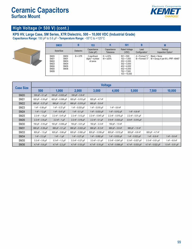
99
Ceramic CapacitorsSurface Mount
High Voltage (> 500 V) (cont.)KPS HV, Large Case, SM Series, X7R Dielectric, 500 – 10,000 VDC (Industrial Grade)Capacitance Range: 150 pF to 5.6 μF • Temperature Range: −55°C to +125°C
• Large Case Sizes (≥ • Formed “ ” or “ ” ad
.5 V, a d 1 it n f i g
Order ng Information
SM20 B 153 K 501 B M
Style/Size Dielectric CapacitanceCode (pF)
CapacitanceTolerance
Rated Voltage (VDC)
LeadConfi guration1
Testing/ Inspection Option2
SM20SM21SM22SM23SM24SM25SM26
SM30SM31SM33SM34SM35SM36
B = X7R 2 signifi cant digits + number
of zeros
K = ±10%M = ±20%
501 = 500102 = 1,000202 = 2,000302 = 3,000402 = 4,000502 = 5,000752 = 7,500103 = 10,000
A = Formed "L"B = Formed "J"
Blank = NoneM = Group A per M L–PRF–49467
Case SizeVoltage
500 1,000 2,000 3,000 4,000 5,000 7,500 10,000SM20 330 pF – 0.1 µF 330 pF – 0.022 µF 330 pF – 3.9 nF
SM21 820 pF – 0.18 µF 820 pF – 0.068 µF 820 pF – 0.012 µF 820 pF – 4.7 nF
SM22 680 pF – 0.27 µF 680 pF – 0.1 µF 680 pF – 0.015 µF 680 pF – 5.6 nF
SM23 1 nF – 0.56 µF 1 nF – 0 27 µF 1 nF – 0.033 µF 1 nF – 0.015 µF 1 nF – 6.8 nF
SM24 1 nF – 1 2 µF 1 nF – 0.47 µF 1 nF – 0.1 µF 1 nF – 0.033 µF 1 nF – 0.012 µF 1 nF – 6.8 nF
SM25 2.2 nF – 1.8 µF 2.2 nF – 0.47 µF 2.2 nF – 0.12 µF 2.2 nF – 0.047 µF 2.2 nF – 0.015 µF 2.2 nF – 0.01 µF
SM26 2.2 nF – 2.9 µF 2.2 nF – 1 µF 2.2 nF – 0.18 µF 2.2 nF – 0.1 µF 3 9 nF – 0.033 µF 3.9 nF – 0.015 µF
SM30 150 pF – 0.18 µF 150 pF – 0.056 µF 150 pF – 0.01 µF 150 pF – 3.3 nF 150 pF – 1.5 nF
SM31 680 pF – 0.39 µF 680 pF – 0.1 µF 680 pF – 0.022 µF 680 pF – 8 2 nF 680 pF – 3.9 nF 680 pF – 1.5 nF
SM33 820 pF – 1.5 µF 820 pF – 0.68 µF 820 pF – 0.082 µF 820 pF – 0.039 µF 820 pF – 0.012 µF 820 pF – 6.8 nF 820 pF – 4.7 nF
SM34 1 nF – 2 2 µF 1 nF – 1 µF 1 nF – 0.27 µF 1 nF – 0.082 µF 1 nF – 0.033 µF 1 nF – 0.022 µF 1 nF – 6.8 nF 1 nF – 5.6 nF
SM35 3.3 nF – 3.9 µF 3.3 nF – 1.2 µF 3.3 nF – 0.27 µF 3.3 nF – 0.1 µF 3 3 nF – 0.047 µF 3.3 nF – 0.027 µF 3 3 nF – 0.01 µF 1 nF – 6.8 nF
SM36 4.7 nF – 5.6 µF 4.7 nF – 2.2 µF 4.7 nF – 0 33 µF 4.7 nF – 0.15 µF 4.7 nF – 0.068 µF 4.7 nF – 0.033 µF 4.7 nF – 0.022 µF 1.5 nF – 0.01 µF
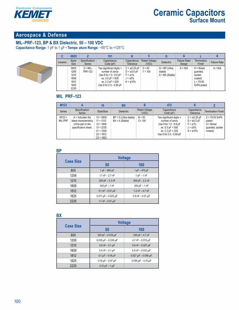
100
Ceramic CapacitorsSurface Mount
Aerospace & Defense MIL–PRF–123, BP & BX Dielectric, 50 – 100 VDCCapacitance Range: 1 pF to 1 μF • Tempe ature Range: −55°C to +125°C
r e ng a on
C 0805 Z 101 K 5 G A L A
Ceramic Style/Size
Specifi cation/Series
CapacitanceCode (pF)
CapacitanceTolerance
Rated Voltage (VDC) Dielectric Failure Rate/
DesignTermination
Finish Failure Rate
0805120612101808181218252225
Z = MIL-PRF-123
Two signifi cant digits + number of zeros
Use 9 for 1 0 - 9 9 pFex. 0.5 pF = 508ex. 2.2 pF = 229
Use 8 for 0 5 - 0 99 pF
C = ±0.25 pFD = ±0.5 pFF = ±1%J = ±5%K = ±10%
5 = 501 = 100
G = BP (Ultra-stable)X = BX (Stable)
A = N/A H = Nickel guarded, (solder coated)L = 70/30 SnPb plated
A = N/A
MIL PRF–123
Orde ing Informat on
0805 Z 101 K 5 G A A
Cerami Style/Size
Spe ifi cati n/Ser es
CapacitanceC de (pF)
Capacitan eTolerance
Rated V tage (VDC) Dielectr c Fai ure Rate/
DesignTerm nation
Finish Fai ure R te
0805206
121018081812825
2225
Z = MIL-PRF 23
Two sign fi cant digits number of zeros
Use 9 f r 1 0 9 9 pFe 0 5 pF = 508ex 2 2 pF = 229
Use 8 for 0 5 0 99 pF
C = ±0 25 pFD = ±0 5 pFF = ±1%J = ±5%K = ± 0%
5 = 50 = 00
G = BP (Ultrastable)X = BX (Stable)
A = N/A H = Nicke guarded, (so der coated) = 0/30
SnPb plated
A = N/A
MIL–PRF– 23
M123 A 10 BX B 472 K ZSeries Specifi cation/
Series Style/Size Dielectric Rated Voltage (VDC)
CapacitanceCode (pF)
CapacitanceTolerance Termination Finish
M123 = MIL-PRF
A = Indicates the latest characteristics
of the part in the specifi cation sheet.
10 = 0805 11 = 1210 12 = 1808 13 = 2225 21 = 1206 22 = 1812 23 = 1825
BP = G (Ultra-stable)BX = X (Stable)
B = 50C= 100
Two signifi cant digits + number of zeros
Use 9 for 1.0 - 9 9 pFex. 0.5 pF = 508ex. 2.2 pF = 229
Use 8 for 0.5 - 0.99 pF
C = ±0.25 pFD = ±0.5 pFF = ±1%J = ±5%K = ±10%
Z = 70/30 SnPb platedS = Nickel guarded, (solder coated)
BP
Case SizeVoltage
50 100805 1 pF – 680 pF 1 pF – 470 pF
1206 1.1 nF – 2.7 nF 1 pF – 1 nF
1210 300 pF – 3.3 nF 300 pF – 2.2 nF
1808 300 pF – 1 nF 300 pF – 1 nF
1812 5.1 nF – 0.01 µF 1.2 nF – 4.7 nF
1825 0.011 µF – 0.022 µF 3.9 nF – 0.01 µF
2225 1.1 nF – 0.01 µF
BX
Case SizeVoltage
50 100805 330 pF – 0.018 µF 330 pF – 4.7 nF
1206 0.018 µF – 0.039 µF 4.7 nF – 0.015 µF
1210 5.6 nF – 0.1 µF 5.6 nF – 0.027 µF
1808 5.6 nF – 0.1 µF 5.6 nF – 0.033 µF
1812 0.1 µF – 0.18 µF 0.027 µF – 0.056 µF
1825 0.18 µF – 0.47 µF 0.056 µF – 0.15 µF
2225 0.12 µF – 1 µF

101
Ceramic CapacitorsSurface Mount
Aerospace & Defense (cont.)GR900 High Reliability Series, BP & BX Dielectric, 16 – 200 VDCCapacitance Range: 1 pF to 1 μF Temperature Range: −55°C to +125°C
r e ing Informat on
C 0805 A 103 K 5 X A C ACeramic Style/Size Specifi cation/
SeriesCapacitanceCode (pF)
CapacitanceTolerance
Rated Voltage (VDC) Dielectric Failure Rate/
DesignTermination
Finish Failure Rate
0504080510051206121018051808181218252225
A = GR900Q = Q-Spec
Two signifi cant digits + number of zeros
Use 9 for 1.0 - 9.9 pFex. 0.5 pF = 508ex. 2.2 pF = 229
Use 8 for 0.5 - 0 99 pF
C = ±0.25 pFD = ±0.5 pFF = ±1%G = ±2%J = ±5%K = ±10%M = ±20%
1 = 1002 = 2003 =254 = 165 = 50
G = BP (Ultra-stable)X = BX (Stable)
A = N/A C = 100% Tin platedH = 60/40 SnPb coatedL = 70/30 SnPb platedG = Gold plated
A = N/A
BP
Case SizeVoltage
16 50 100 2000504 150 pF – 180 pF 91 pF – 130 pF 1 pF – 82 pF
0805 510 pF – 560 pF 240 pF – 470 pF 1 pF – 220 pF
1005 910 pF – 1.2 nF 510 pF – 820 pF 1 pF – 470 pF
1206 4.7 nF – 5.6 nF 1.8 nF – 2 nF 510 pF – 1.6 nF 10 pF – 470 pF
1210 0.01 µF 3.6 nF 1.1 nF – 3.3 nF 10 pF – 1 nF
1805 1.6 nF – 2.2 nF 510 pF – 1 5 nF 220 pF – 470 pF
1808 5.1 nF – 5.6 nF 1.6 nF – 4.7 nF 330 pF – 1.5 nF
1812 7.5 nF – 0.01 µF 3 nF – 6.8 nF 330 pF – 2.7 nF
1825 0.02 µF – 0.022 µF 6 2 nF – 0.018 µF 2.7 nF – 5.6 nF
2225 0.024 µF – 0.033 µF 9.1 nF – 0.022 µF 2.7 nF – 8.2 nF BX
Case SizeVoltage
16 25 50 100 2000504 1.5 nF – 6.8 nF 360 pF – 1 2 nF 220 pF – 330 pF
0805 0.1 µF 5.6 nF – 0.047 µF 1 nF – 4.7 nF 180 pF – 820 pF
1005 0.012 µF – 0.022 µF 2.2 nF – 0.01 µF 330 pF – 1.8 nF
1206 0.018 µF – 0.15 µF 5.6 nF – 0.015 µF 470 pF – 4.7 nF
1210 0.47 µF 0 33 µF 0.039 µF – 0.1 µF 0.012 µF – 0.1 µF 470 pF – 0.01 µF
1805 0.018 µF – 0.047 µF 4.7 nF – 0.018 µF 1 2 nF – 3 9 nF
1808 0.039 µF – 0.1 µF 0.012 µF – 0.047 µF 2.2 nF – 0.01 µF
1812 0.082 µF – 0.18 µF 0.022 µF – 0.082 µF 6.8 nF – 0.018 µF
1825 0.18 µF – 0.47 µF 0.056 µF – 0.18 µF 0.01 µF – 0.047 µF
2225 0.22 µF – 1 µF 0.056 µF – 0.18 µF 0.018 µF – 0.047 µF
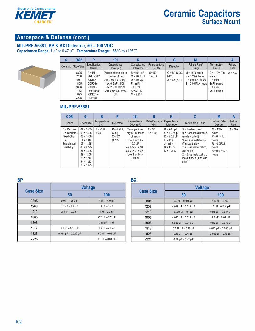
102
Ceramic CapacitorsSurface Mount
Aerospace & Defense (cont.) MIL-PRF-55681, BP & BX Dielectric, 50 – 100 VDCCapacitance Range: 1 pF to 0.47 μF Temperature Range: −55°C to +125°C
rde ng In ormation
C 0805 P 101 K 1 G M L ACeramic Style/Size Specifi cation/
SeriesCapacitanceCode (pF)
CapacitanceTolerance
Rated Voltage (VDC) Dielectric Failure Rate/
DesignTermination
FinishFailure Rate
08051206121180518081 1218252225
P = MI -PRF-55681(CDR01 – CDR06)N = MI -PRF-55681(CDR31 – CDR35)
Two signifi cant digits + number of zeros
Use 9 for 1.0 - 9.9 pFex. 0.5 pF = 508ex. 2.2 pF = 229
Use 8 for 0.5 - 0.99 pF
B = ±0.1 pFC = ±0.25 pFD = ±0.5 pFF = ±1%J = ±5%K = ±1 %M = ±20%
5 = 50 1 = 100
G = BP (C0G, NP0)X = BX (X7R)
M = 1%/k hou s P = 0.1%/k hours R = 0.01%/k hours S = 0.001%/k hours
C = 1 0% Tin platedH = 60/4 SnPb platedL = 70/30 SnPb plated
A = N/A
MIL-PRF-55681
Orderin Informat on
C 8 5 P 1 1 1 G M L ACeram c Sty e/Size Spec fi cation
SeriesCapacitanceCode (pF)
CapacitanceTo erance
Rated Voltage (VDC) Dielectr c Fa lure Rate
DesignTermination
Fin shFai ure Rate
08051206121018051808181218252225
P = MIL-PRF 55681CDR01 –
CDR06)N = MIL-PRF-55681(CDR31 CDR 5
Tw sign fi cant digits + numbe of zeros
Use 9 for 1 0 - 9.9 pFex 0 5 pF 508e 2.2 pF = 229se 8 f r 0.5 - 0.99
pF
B = ±0 1 pFC ±0 25 pFD = ±0.5 pFF ±1%J = ±5K = ±10M ±20%
5 = 50 1 100
G = BP C0G NP0)X = BX X7R
M = 1%/k h urs P 0 1%/k hours R = 0 01%/k hours S 0 001%/k hours
C = 100 Tin platedH = 60/40 SnPb platedL = 70/ 0 SnPb plated
A = N/A
MIL–PRF 55681
CDR 01 B P 101 B K Z M ASeries Style/Size Temperature
( C ) Dielectric CapacitanceCode (pF)
Rated Voltage (VDC)
CapacitanceTolerance Termination Finish Failure Rate/
DesignFailure Rate
C = CeramicD = Dielectric,Fixed ChipR = Established Reliability
01 = 080502 = 180503 = 180804 = 181205 = 182506 = 222531 = 080532 = 120633 = 121034 = 181235 = 1825
B = -55 to +125
P = G (BP, C0G) X = BX (X7R)
Two signifi cant digits + number
of zerosUse 9 for 1.0 -
9.9 pFex. 0.5 pF = 508ex. 2 2 pF = 229Use 8 for 0.5 -
0.99 pF
A = 50 B = 100
B = ±0.1 pFC = ±0.25 pFD = ±0.5 pFF = ±1%J = ±5%K = ±10%M = ±20%
S = Solder coatedU = Base metallization, (solder coated)W = Base metaliation, (Tin/Lead alloy)Y = Base metalization, (100% Tin)Z = Base metalization, metal-tinned (Tin/Lead alloy)
M = 1%/k hours P = 0.1%/k hours R = 0.01%/k hours S = 0.001%/k hours
A = N/A
BP
Case SizeVoltage
50 1000805 510 pF – 680 pF 1 pF – 470 pF
1206 1.1 nF – 2.2 nF 1 pF – 1 nF
1210 2.4 nF – 3.3 nF 1 nF – 2.2 nF
1805 220 pF – 270 pF
1808 330 pF – 1 nF
1812 5.1 nF – 0.01 µF 1.2 nF – 4.7 nF
1825 0.011 µF – 0.022 µF 3 9 nF – 0.01 µF
2225 6.8 nF – 0.01 µF
BX
Case SizeVoltage
50 1000805 3.9 nF – 0.018 µF 120 pF – 4.7 nF
1206 0.018 µF – 0.039 µF 4.7 nF – 0.015 µF
1210 0.039 µF – 0.1 µF 0.015 µF – 0.027 µF
1805 0.012 µF – 0.022 µF 3 9 nF – 0.01 µF
1808 0.039 µF – 0.068 µF 0.012 µF – 0.033 µF
1812 0.082 µF – 0.18 µF 0.027 µF – 0.056 µF
1825 0.18 µF – 0.47 µF 0.056 µF – 0.15 µF
2225 0.39 µF – 0.47 µF
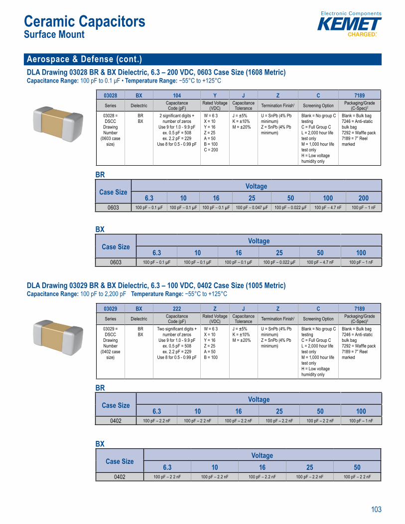
103
Ceramic CapacitorsSurface Mount
Aerospace & Defense (cont.)DLA Drawing 03028 BR & BX Dielectric, 6.3 – 200 VDC, 0603 Case Size (1608 Metric)Capacitance Range: 100 pF to 0.1 μF • Temperature Range: −55°C to +125°C
Order n nformation
03028 BX 104 Y J Z C 7189Series Dielectric Capacitance
Code (pF)Rated Voltage
(VDC)Capacitance
Tolerance Termination Finish1 Screening Option Packaging/Grade (C-Spec)2
03028 = DSCC
Drawing Number
(0603 case size)
BRBX
2 signifi cant digits + number of zeros
Use 9 for 1.0 - 9.9 pFex. 0.5 pF = 508ex. 2.2 pF = 229
Use 8 for 0.5 - 0.99 pF
W = 6 3X = 10Y = 16Z = 25A = 50B = 100C = 200
J = ±5%K = ±10%M = ±20%
U = SnPb (4% Pb minimum)Z = SnPb (4% Pb minimum)
Blank = No group C testingC = Full Group CL = 2,000 hour life test onlyM = 1,000 hour life test onlyH = Low voltage humidity only
Blank = Bulk bag7246 = Anti-static bulk bag7292 = Waffl e pack7189 = 7” Reel marked
BR
Case SizeVoltage
6.3 10 16 25 50 100 2000603 100 pF – 0.1 µF 100 pF – 0.1 µF 100 pF – 0.1 µF 100 pF – 0.047 µF 100 pF – 0.022 µF 100 pF – 4.7 nF 100 pF – 1 nF
BX
Case SizeVoltage
6.3 10 16 25 50 1000603 100 pF – 0.1 µF 100 pF – 0.1 µF 100 pF – 0.1 µF 100 pF – 0.022 µF 100 pF – 4.7 nF 100 pF – 1 nF
DLA Drawing 03029 BR & BX Dielectric, 6.3 – 100 VDC, 0402 Case Size (1005 Metric)Capacitance Range: 100 pF to 2,200 pF Temperature Range: −55°C to +125°C
pp o
Ordering I format on
03029 BX 222 Z J Z C 7189Series Dielectric Capacitance
Code (pF)Rated Voltage
(VDC)Capacitance
Tolerance Termination Finish1 Screening Option Packaging/Grade (C-Spec)2
03029 = DSCC
Drawing Number
(0402 case size)
BRBX
Two signifi cant digits + number of zeros
Use 9 for 1.0 - 9.9 pFex. 0.5 pF = 508ex. 2.2 pF = 229
Use 8 for 0.5 - 0.99 pF
W = 6 3X = 10Y = 16Z = 25A = 50B = 100
J = ±5%K = ±10%M = ±20%
U = SnPb (4% Pb minimum)Z = SnPb (4% Pb minimum)
Blank = No group C testingC = Full Group CL = 2,000 hour life test onlyM = 1,000 hour life test onlyH = Low voltage humidity only
Blank = Bulk bag7246 = Anti-static bulk bag7292 = Waffl e pack7189 = 7” Reel marked
BR
Case SizeVoltage
6.3 10 16 25 50 1000402 100 pF – 2.2 nF 100 pF – 2 2 nF 100 pF – 2.2 nF 100 pF – 2.2 nF 100 pF – 2 2 nF 100 pF – 1 nF
BX
Case SizeVoltage
6.3 10 16 25 500402 100 pF – 2 2 nF 100 pF – 2.2 nF 100 pF – 2.2 nF 100 pF – 2.2 nF 100 pF – 2 2 nF
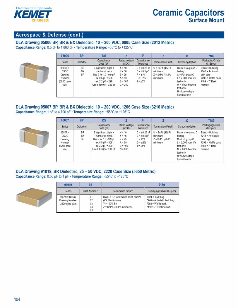
104
Ceramic CapacitorsSurface Mount
Aerospace & Defense (cont.)DLA Drawing 05006 BP, BR & BX Dielectric, 10 – 200 VDC, 0805 Case Size (2012 Metric)Capacitance Range: 0.5 pF to 1,800 pF • Temperature Range: −55°C to +125°C
Ordering I ormat o
05006 BP 681 Z F Z C 7189Series Dielectric Capacitance
Code (pF)Rated Voltage
(VDC)Capacitance
Tolerance Termination Finish1 Screening Option Packaging/Grade (C-Spec)2
05006 = DSCC
Drawing Number
(0805 case size)
BRBXBP
2 signifi cant digits + number of zeros
Use 9 for 1.0 - 9.9 pFex. 0.5 pF = 508ex. 2.2 pF = 229
Use 8 for 0.5 - 0.99 pF
X = 10Y = 16Z = 25A = 50B = 100C = 200
C = ±0.25 pFD = ±0.5 pFF = ±1%G = ±2%J = ±5%
U = SnPb (4% Pb minimum)Z = SnPb (4% Pb minimum)
Blank = No group C testingC = Full group CL = 2,000 hour life test onlyM = 1,000 hour life test onlyH = Low voltage humidity only
Blank = Bulk bag7246 = Anti-static bulk bag7292 = Waffl e pack7189 = 7” Reel marked
DLA Drawing 05007 BP, BR & BX Dielectric, 10 – 200 VDC, 1206 Case Size (3216 Metric)Capacitance Range: 1 pF to 4,700 pF • Temperature Range: −55°C to +125°C
Order n nformation
05007 BP 222 Z F Z C 7189Series Dielectric Capacitance
Code (pF)Rated Voltage
(VDC)Capacitance
Tolerance Termination Finish1 Screening Option Packaging/Grade (C-Spec)2
05007 = DSCC
Drawing Number
(1206 case size)
BRBXBP
2 signifi cant digits + number of zeros
Use 9 for 1.0 - 9.9 pFex. 0.5 pF = 508ex. 2.2 pF = 229
Use 8 for 0.5 - 0.99 pF
X = 10Y = 16Z = 25A = 50B = 100C = 200
C = ±0.25 pFD = ±0.5 pFF = ±1%G = ±2%J = ±5%
U = SnPb (4% Pb minimum)Z = SnPb (4% Pb minimum)
Blank = No group C testingC = Full group CL = 2,000 hour life test onlyM = 1,000 hour life test onlyH = Low voltage humidity only
Blank = Bulk bag7246 = Anti-static bulk bag7292 = Waffl e pack7189 = 7” Reel marked
DLA Drawing 91019, BR Dielectric, 25 – 50 VDC, 2220 Case Size (5650 Metric)Capacitance Range: 0.56 μF to 1 μF • Temperature Range: −55°C to +125°C
r e
DSCC Appro
O derin Informat on
91019 01 - 7189
Series Dash Number1 Termination Finish2 Packaging/Grade (C-Spec)
91019 = DSCC Drawing Number(2220 case size)
0102030405
Blank = "U" termination fi nish / SnPb (4% Pb minimum)Y = 100% SnZ = SnPb (4% Pb minimum)
Blank = Bulk bag7246 = Anti-static bulk bag7292 = Waffl e pack7189 = 7” Reel marked
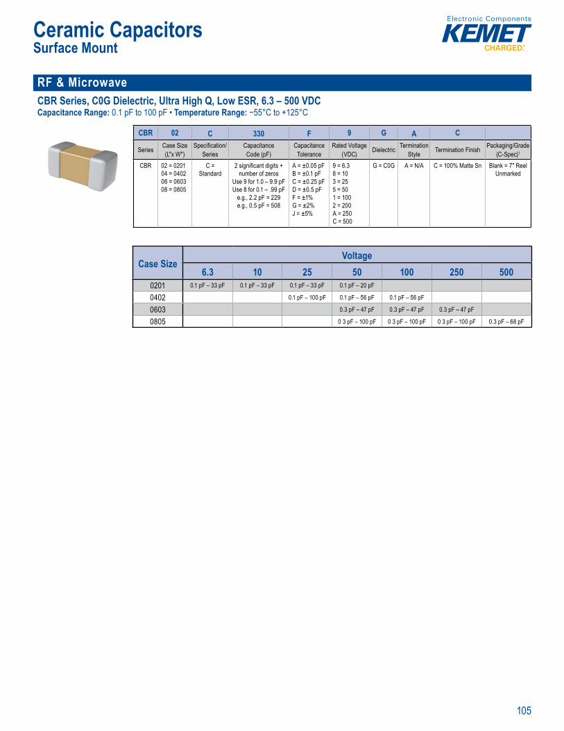
105
Ceramic CapacitorsSurface Mount
RF & MicrowaveCBR Series, C0G Dielectric, Ultra High Q, Low ESR, 6.3 – 500 VDCCapacitance Range: 0.1 pF to 100 pF • Temperature Range: −55°C to +125°C
0201 0 02, 06 3, an
• DC volt ge ati g of
Order ng Information
CBR 02 C 330 F 9 G A C
Series Case Size(L"x W")
Specifi cation/Series
CapacitanceCode (pF)
CapacitanceTolerance
Rated Voltage (VDC) Dielectric Termination
Style Termination Finish Packaging/Grade(C-Spec)1
CBR 02 = 020104 = 040206 = 060308 = 0805
C = Standard
2 signifi cant digits + number of zeros
Use 9 for 1.0 – 9.9 pFUse 8 for 0.1 – .99 pF
e.g., 2.2 pF = 229e.g., 0.5 pF = 508
A = ±0.05 pFB = ±0.1 pFC = ±0.25 pFD = ±0.5 pFF = ±1%G = ±2%J = ±5%
9 = 6.38 = 103 = 255 = 501 = 1002 = 200A = 250C = 500
G = C0G A = N/A C = 100% Matte Sn Blank = 7" Reel Unmarked
Case SizeVoltage
6.3 10 25 50 100 250 5000201 0.1 pF – 33 pF 0.1 pF – 33 pF 0.1 pF – 33 pF 0.1 pF – 20 pF
0402 0.1 pF – 100 pF 0.1 pF – 56 pF 0.1 pF – 56 pF
0603 0.3 pF – 47 pF 0.3 pF – 47 pF 0.3 pF – 47 pF
0805 0 3 pF – 100 pF 0 3 pF – 100 pF 0 3 pF – 100 pF 0.3 pF – 68 pF
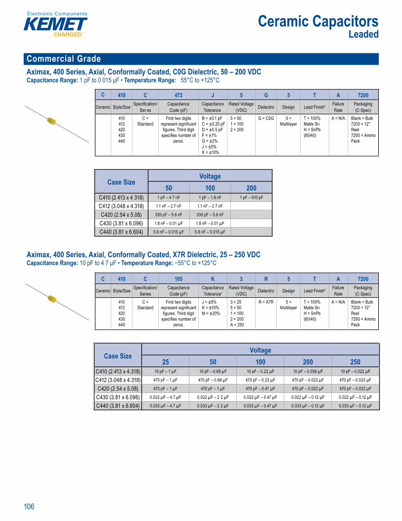
106
Ceramic CapacitorsLeaded
Commercial Grade Aximax, 400 Series, Axial, Conformally Coated, C0G Dielectric, 50 – 200 VDCCapacitance Range: 1 pF to 0 015 μF • Temperature Range: 55°C to +125°C
• H
Order ng nforma ion
C 410 C 472 J 5 G 5 T A 7200
Ceramic Style/Size Specifi cation/Ser es
CapacitanceCode (pF)
CapacitanceTolerance
Rated Voltage (VDC) Dielectric Design Lead Finish2 Failure
RatePackaging(C-Spec)
410412420430440
C = Standard
First two digits represent signifi cant fi gures. Third digit
specifi es number of zeros.
B = ±0.1 pFC = ±0.25 pFD = ±0.5 pFF = ±1%G = ±2%J = ±5%K = ±10%
5 = 501 = 1002 = 200
G = C0G 5 = Multilayer
T = 100% Matte Sn H = SnPb (60/40)
A = N/A Blank = Bulk7200 = 12" Reel 7293 = Ammo Pack
Case SizeVoltage
50 100 200C410 (2 413 x 4 318) 1 pF – 4 7 nF 1 pF – 1.8 nF 1 pF – 510 pF
C412 (3.048 x 4.318) 1 1 nF – 2.7 nF 1.1 nF – 2 7 nF
C420 (2.54 x 5.08) 330 pF – 5.6 nF 330 pF – 5.6 nF
C430 (3.81 x 6.096) 1.8 nF – 0.01 µF 1.8 nF – 0.01 µF
C440 (3.81 x 6.604) 5.6 nF – 0.015 µF 5.6 nF – 0.015 µF Aximax, 400 Series, Axial, Conformally Coated, X7R Dielectric, 25 – 250 VDCCapacitance Range: 10 pF to 4 7 μF • Temperature Range: −55°C to +125°C
Temperature ic V 1 250 Ca acit n e offer ng ng f om 10 F vail ble ca aci ance ance o ±5 % a d ±2 % Hig t m er ture so a att N pol r e ice i g i a t o e s
i i y
capac tors n X7R dielectri feature a 1 5 C m ximum o eratin t m e a ure T e Electronics In ust ies Al iance (EIA) c aracter
m s of sifi d, c c
by ass a up i g a s or for d i g circu e Q and s capacita
cap citance
T se t outl n L Sta
ade)
O de in Information
C 410 C 105 K 3 R 5 T A 7200
Ceramic Style/Size Specifi cation/Series
CapacitanceCode (pF)
CapacitanceTolerance1
Rated Voltage (VDC) Dielectric Design Lead Finish2 Failure
RatePackaging(C-Spec)
410412420430440
C = Standard
First two digits represent signifi cant fi gures. Third digit
specifi es number of zeros.
J = ±5%K = ±10%M = ±20%
3 = 255 = 501 = 1002 = 200A = 250
R = X7R 5 = Multilayer
T = 100% Matte Sn H = SnPb (60/40)
A = N/A Blank = Bulk7200 = 12" Reel 7293 = Ammo Pack
Case SizeVoltage
25 50 100 200 250C410 (2.413 x 4.318) 10 pF – 1 µF 10 pF – 0.68 µF 10 pF – 0.22 µF 10 pF – 0.056 µF 10 pF – 0.022 µF
C412 (3.048 x 4.318) 470 pF – 1 µF 470 pF – 0.68 µF 470 pF – 0.22 µF 470 pF – 0.022 µF 470 pF – 0.022 µF
C420 (2.54 x 5.08) 470 pF – 1 µF 470 pF – 1 µF 470 pF – 0.47 µF 470 pF – 0.022 µF 470 pF – 0.022 µF
C430 (3.81 x 6.096) 0.022 µF – 4.7 µF 0.022 µF – 2 2 µF 0.022 µF – 0.47 µF 0.022 µF – 0.12 µF 0.022 µF – 0.12 µF
C440 (3.81 x 6.604) 0.033 µF – 4.7 µF 0.033 µF – 2 2 µF 0.033 µF – 0.47 µF 0.033 µF – 0.12 µF 0.033 µF – 0.12 µF
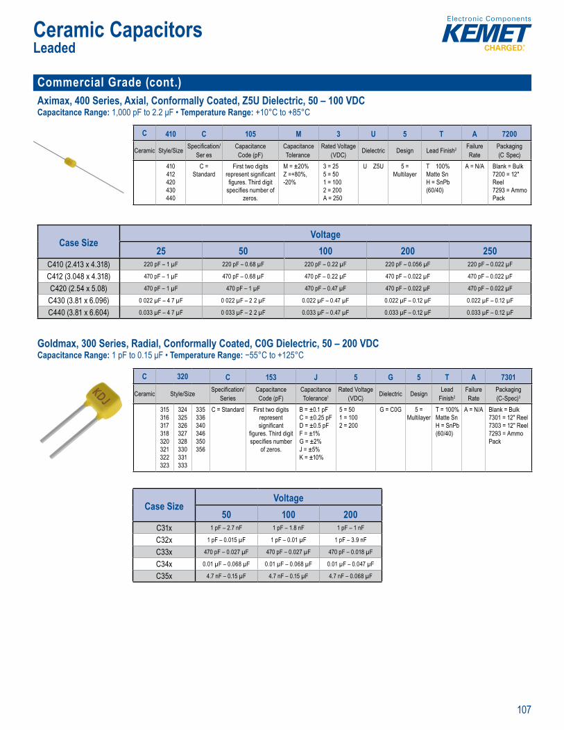
107
Ceramic CapacitorsLeaded
Commercial Grade (cont.)Aximax, 400 Series, Axial, Conformally Coated, Z5U Dielectric, 50 – 100 VDCCapacitance Range: 1,000 pF to 2.2 μF • Temperature Range: +10°C to +85°C
e
• Non pola device min •
Order ng I ormation
C 410 C 105 M 3 U 5 T A 7200
Ceramic Style/Size Specifi cation/Ser es
CapacitanceCode (pF)
CapacitanceTolerance
Rated Voltage (VDC) Dielectric Design Lead Finish2 Failure
RatePackaging(C Spec)
410412420430440
C = Standard
First two digits represent signifi cant fi gures. Third digit
specifi es number of zeros.
M = ±20%Z =+80%, -20%
3 = 255 = 501 = 1002 = 200A = 250
U Z5U 5 = Multilayer
T 100% Matte Sn H = SnPb (60/40)
A = N/A Blank = Bulk7200 = 12" Reel 7293 = Ammo Pack
Case Size
Voltage25 50 100 200 250
C410 (2.413 x 4.318) 220 pF – 1 µF 220 pF – 0.68 µF 220 pF – 0.22 µF 220 pF – 0.056 µF 220 pF – 0.022 µF
C412 (3.048 x 4.318) 470 pF – 1 µF 470 pF – 0.68 µF 470 pF – 0.22 µF 470 pF – 0.022 µF 470 pF – 0.022 µF
C420 (2.54 x 5.08) 470 pF – 1 µF 470 pF – 1 µF 470 pF – 0.47 µF 470 pF – 0.022 µF 470 pF – 0.022 µF
C430 (3.81 x 6.096) 0 022 µF – 4 7 µF 0 022 µF – 2 2 µF 0.022 µF – 0.47 µF 0.022 µF – 0.12 µF 0.022 µF – 0.12 µF
C440 (3.81 x 6.604) 0.033 µF – 4 7 µF 0 033 µF – 2 2 µF 0.033 µF – 0.47 µF 0.033 µF – 0.12 µF 0.033 µF – 0.12 µF
Goldmax, 300 Series, Radial, Conformally Coated, C0G Dielectric, 50 – 200 VDCCapacitance Range: 1 pF to 0.15 μF • Temperature Range: −55°C to +125°C
a ia d , t t Le (P ) F e RE H ompl DC oltage ati 100 V a d 200
co formall ted radial l ceramic it i G ectric 125°C m operati
e. T on st ie All ance A) c aract ele s a Clas "stable" material C mponent ti comp s ing
t cir e wh
in capa e and ts a neglii le i c f mbi mperatur
ce chan l m ± 0 pp f om -5 C to + 25
T t t r i ed St
5 200 V
Orde in Information
C 320 C 153 J 5 G 5 T A 7301
Ceramic Style/Size Specifi cation/Series
CapacitanceCode (pF)
CapacitanceTolerance1
Rated Voltage (VDC) Dielectric Design Lead
Finish2Failure Rate
Packaging(C-Spec)3
315316317318320321322323
324325326327328330331333
335336340346350356
C = Standard First two digits represent signifi cant
fi gures. Third digit specifi es number
of zeros.
B = ±0.1 pFC = ±0.25 pFD = ±0.5 pFF = ±1%G = ±2%J = ±5%K = ±10%
5 = 501 = 1002 = 200
G = C0G 5 = Multilayer
T = 100% Matte Sn H = SnPb (60/40)
A = N/A Blank = Bulk7301 = 12" Reel 7303 = 12" Reel7293 = Ammo Pack
Case SizeVoltage
50 100 200C31x 1 pF – 2.7 nF 1 pF – 1.8 nF 1 pF – 1 nF
C32x 1 pF – 0.015 µF 1 pF – 0.01 µF 1 pF – 3.9 nF
C33x 470 pF – 0.027 µF 470 pF – 0.027 µF 470 pF – 0.018 µF
C34x 0.01 µF – 0.068 µF 0.01 µF – 0.068 µF 0.01 µF – 0.047 µF
C35x 4.7 nF – 0.15 µF 4.7 nF – 0.15 µF 4.7 nF – 0.068 µF

108
Ceramic CapacitorsLeaded
Commercial Grade (cont.)Goldmax, 300 Series, Radial, Conformally Coated, X7R Dielectric, 25 – 250 VDCCapacitance Range: 100 pF to 10 μF • Temperature Range: −55°C to +125°C
O erin n o mation
C 320 C 106 K 3 R 5 T A 7301
Ceramic Style/Size Specifi cation/Series
CapacitanceCode (pF)
CapacitanceTolerance1
Rated Voltage (VDC) Dielectric Design Lead
Finish2Failure Rate
Packaging(C-Spec)3
315316317318320321322323
324325326327328330331333
335336340346350356
C = Standard First two digits represent signifi cant
fi gures. Third digit specifi es number
of zeros.
J = ±5%K = ±10%M = ±20%
3 = 255 = 501 = 1002 = 200A = 250
R = X7R 5 = Multilayer
T = 100% Matte Sn H = SnPb (60/40)
A = N/A Blank = Bulk7301 = 12" Reel 7303 = 12" Reel 7293 = Ammo Pack
Case SizeVoltage
25 50 100 200 250C31x 100 pF – 1 µF 100 pF – 0.68 µF 100 pF – 0.22 µF 100 pF – 0.056 µF 100 pF – 0.056 µF
C32x 100 pF – 10 µF 100 pF – 4.7 µF 100 pF – 0.47 µF 100 pF – 0.15 µF 180 pF – 0.15 µF
C33x 4.7 nF – 2 2 µF 4.7 nF – 2.2 µF 4.7 nF – 1.2 µF 4.7 nF – 1.2 µF 4.7 nF – 1.2 µF
C34x 0.068 µF – 10 µF 0.068 µF – 10 µF 0.068 µF – 2.2 µF 0.068 µF – 1.2 µF 0.068 µF – 1.2 µF
C35x 0.18 µF – 10 µF 0.18 µF – 10 µF 0.18 µF – 1.2 µF 0.18 µF – 1.2 µF 0.18 µF – 1.2 µF
Goldmax, 300 Series, Radial, Conformally Coated, Z5U Dielectric, 50 – 250 VDCCapacitance Range: 100 pF to 10 μF • Temperature Range: +10°C to +85°C
ma ly , 0 2 0 l t g t m e r lt e
Overv
ax fo l co ted d al e ed c mi in ct maximu era ing
u e d a on l-purp se ” The s I tr lli cterizes Z5U
s t i am ie e
cou the t o ich diel tric sses, high ul t i nc stab o of ajor po tan table c paci nce th res ri t
Ra ial Leade
Goldmax, 300 Series, Conformal y oa d, Z5U 5 – 2 VDC Comm rcia Grade
Or ering nformat on
C 335 C 225 M 5 U 5 T A 7303
Ceramic Style/Size Specifi cation/Series
CapacitanceCode (pF)
CapacitanceTolerance1
Rated Voltage (VDC) Dielectric Design Lead
Finish2Failure Rate
Packaging(C-Spec)3
315316317318320321322323
324325326327328330331333
335336340346350356
C = Standard First two digits represent signifi cant
fi gures. Third digit specifi es number
of zeros.
M = ±20%Z = +80%, -20%
3 = 255 = 501 = 1002 = 200A = 250
U = Z5U 5 = Multilayer
T = 100% Matte Sn H = SnPb (60/40)
A = N/A Blank = Bulk7301 = 12" Reel 7303 = 12" Reel 7293 = Ammo Pack
Case SizeVoltage
25 50 100 200 250C31x 100 pF – 1 µF 100 pF – 0.68 µF 100 pF – 0.22 µF 100 pF – 0.056 µF 100 pF – 0.056 µF
C32x 100 pF – 10 µF 100 pF – 4.7 µF 100 pF – 0.47 µF 100 pF – 0.15 µF 100 pF – 0.15 µF
C33x 4.7 nF – 2.2 µF 4.7 nF – 2.2 µF 4.7 nF – 1 2 µF 4.7 nF – 1.2 µF 4.7 nF – 1.2 µF
C34x 0.068 µF – 10 µF 0.068 µF – 10 µF 0.068 µF – 2 2 µF 0.068 µF – 1.2 µF 0.068 µF – 1.2 µF
C35x 0.18 µF – 10 µF 0.18 µF – 10 µF 0.18 µF – 1.2 µF 0.18 µF – 1.2 µF 0.18 µF – 1.2 µF
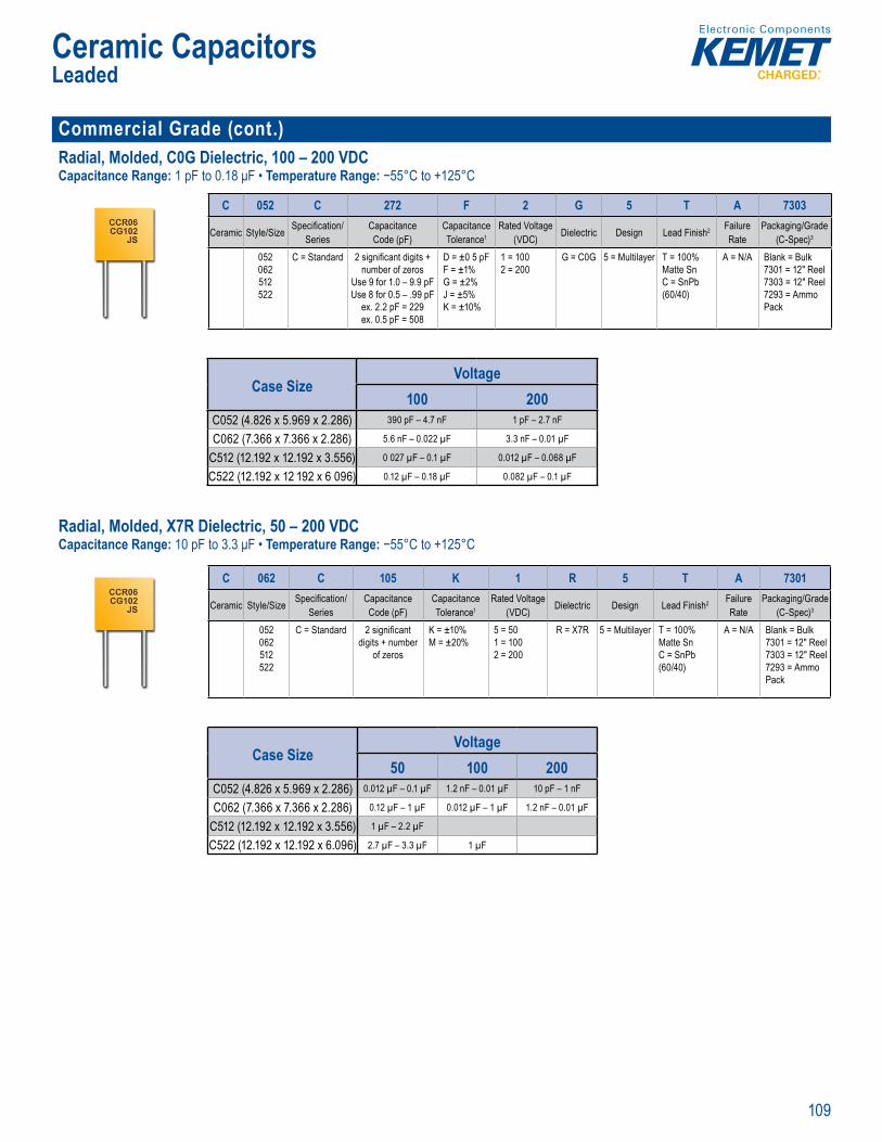
109
Ceramic CapacitorsLeaded
Commercial Grade (cont.)Radial, Molded, C0G Dielectric, 100 – 200 VDCCapacitance Range: 1 pF to 0.18 μF • Temperature Range: −55°C to +125°C
Ava able c pac ta ce
a d 1 % gh pple ur
Orde n I f ti n
C 052 C 272 F 2 G 5 T A 7303
Ceramic Style/Size Specifi cation/Series
CapacitanceCode (pF)
CapacitanceTolerance1
Rated Voltage (VDC) Dielectric Design Lead Finish2 Failure
RatePackaging/Grade
(C-Spec)3
052062512522
C = Standard 2 signifi cant digits + number of zeros
Use 9 for 1.0 – 9.9 pFUse 8 for 0.5 – .99 pF
ex. 2.2 pF = 229ex. 0.5 pF = 508
D = ±0 5 pFF = ±1%G = ±2%J = ±5%K = ±10%
1 = 1002 = 200
G = C0G 5 = Multilayer T = 100% Matte SnC = SnPb (60/40)
A = N/A Blank = Bulk7301 = 12" Reel7303 = 12" Reel7293 = Ammo Pack
Case SizeVoltage
100 200C052 (4.826 x 5.969 x 2.286) 390 pF – 4.7 nF 1 pF – 2.7 nF
C062 (7.366 x 7.366 x 2.286) 5.6 nF – 0.022 µF 3.3 nF – 0.01 µF
C512 (12.192 x 12.192 x 3.556) 0 027 µF – 0.1 µF 0.012 µF – 0.068 µF
C522 (12.192 x 12 192 x 6 096) 0.12 µF – 0.18 µF 0.082 µF – 0.1 µF
Radial, Molded, X7R Dielectric, 50 – 200 VDCCapacitance Range: 10 pF to 3.3 μF • Temperature Range: −55°C to +125°C
Compli nt D ol age a i gs o 0 V, 10 d 200 Cap ci anc of erin r gin 0 p o .3 i i i Sn te l fi n sh 6 40
O erview
KEMET’s ep xy mold d rad al thro i X7R die ectric feature an 25 C maximum oper t ng
ct s nd lli hara di
m teri C mp s of h cat on r ce amic
apa uited for y ass and decou ng
a e a s h a with eferen nce c ng is limited
to ± fr m to 1 C Th se es m e fl ame e me s ou i ed n UL a a d –
Radia , Molde
O de in Information
C 062 C 105 K 1 R 5 T A 7301
Ceramic Style/Size Specifi cation/Series
CapacitanceCode (pF)
CapacitanceTolerance1
Rated Voltage (VDC) Dielectric Design Lead Finish2 Failure
RatePackaging/Grade
(C-Spec)3
052062512522
C = Standard 2 signifi cant digits + number
of zeros
K = ±10%M = ±20%
5 = 501 = 1002 = 200
R = X7R 5 = Multilayer T = 100% Matte SnC = SnPb (60/40)
A = N/A Blank = Bulk7301 = 12" Reel 7303 = 12" Reel 7293 = Ammo Pack
Case SizeVoltage
50 100 200C052 (4.826 x 5.969 x 2.286) 0.012 µF – 0.1 µF 1.2 nF – 0.01 µF 10 pF – 1 nF
C062 (7.366 x 7.366 x 2.286) 0.12 µF – 1 µF 0.012 µF – 1 µF 1.2 nF – 0.01 µF
C512 (12.192 x 12.192 x 3.556) 1 µF – 2.2 µF
C522 (12.192 x 12.192 x 6.096) 2.7 µF – 3.3 µF 1 µF
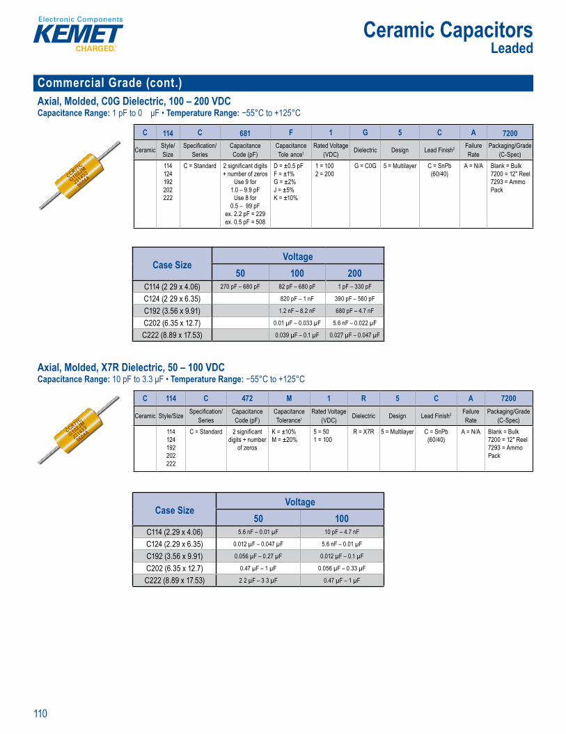
110
Ceramic CapacitorsLeaded
Commercial Grade (cont.)Axial, Molded, C0G Dielectric, 100 – 200 VDCCapacitance Range: 1 pF to 0 μF • Temperature Range: −55°C to +125°C
ul t on meets fl amm bil sta da d L 94 V–0
Ord in nforma ion
C 114 C 681 F 1 G 5 C A 7200
Ceramic Style/Size
Specifi cation/Series
CapacitanceCode (pF)
CapacitanceTole ance1
Rated Voltage (VDC) Dielectric Design Lead Finish2 Failure
RatePackaging/Grade
(C-Spec)114124192202222
C = Standard 2 signifi cant digits + number of zeros
Use 9 for 1.0 – 9.9 pF
Use 8 for 0.5 – 99 pF
ex. 2.2 pF = 229ex. 0.5 pF = 508
D = ±0.5 pFF = ±1%G = ±2%J = ±5%K = ±10%
1 = 1002 = 200
G = C0G 5 = Multilayer C = SnPb (60/40)
A = N/A Blank = Bulk7200 = 12" Reel 7293 = Ammo Pack
Case SizeVoltage
50 100 200C114 (2 29 x 4.06) 270 pF – 680 pF 82 pF – 680 pF 1 pF – 330 pF
C124 (2 29 x 6.35) 820 pF – 1 nF 390 pF – 560 pF
C192 (3.56 x 9.91) 1.2 nF – 8.2 nF 680 pF – 4.7 nF
C202 (6.35 x 12.7) 0.01 µF – 0.033 µF 5.6 nF – 0.022 µF
C222 (8.89 x 17.53) 0.039 µF – 0.1 µF 0.027 µF – 0.047 µF
Axial, Molded, X7R Dielectric, 50 – 100 VDCCapacitance Range: 10 pF to 3.3 μF • Temperature Range: −55°C to +125°C
s
r acitan offe om f o lar d vic m ins l io ns nPb- ated ea fi n ncap ul t o meets 94 V–
capacitors X7R d electr featu
eratin mperature. The Electron cs Industr es Allianc
bl teri po cla e iele c capacitors ed for byp d decoup g
l t ns o equen riminating s where
fro o he s fl am requ –0
O de n I format
C 114 C 472 M 1 R 5 C A 7200
Ceramic Style/Size Specifi cation/Series
CapacitanceCode (pF)
CapacitanceTolerance1
Rated Voltage (VDC) Dielectric Design Lead Finish2 Failure
RatePackaging/Grade
(C-Spec)114124192202222
C = Standard 2 signifi cant digits + number
of zeros
K = ±10%M = ±20%
5 = 501 = 100
R = X7R 5 = Multilayer C = SnPb (60/40)
A = N/A Blank = Bulk7200 = 12" Reel 7293 = Ammo Pack
Case SizeVoltage
50 100C114 (2.29 x 4.06) 5.6 nF – 0.01 µF 10 pF – 4.7 nF
C124 (2.29 x 6.35) 0.012 µF – 0.047 µF 5.6 nF – 0.01 µF
C192 (3.56 x 9.91) 0.056 µF – 0.27 µF 0.012 µF – 0.1 µF
C202 (6.35 x 12.7) 0.47 µF – 1 µF 0.056 µF – 0.33 µF
C222 (8.89 x 17.53) 2 2 µF – 3 3 µF 0.47 µF – 1 µF
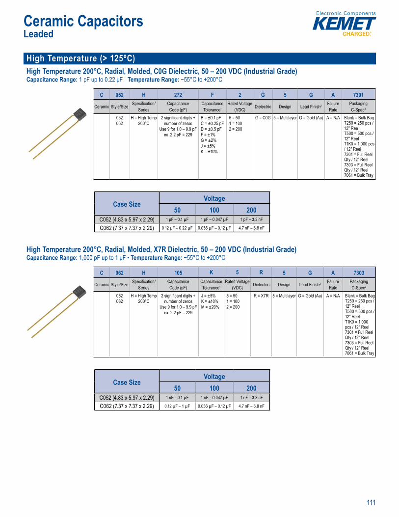
111
Ceramic CapacitorsLeaded
High Temperature (> 125ºC) High Temperature 200°C, Radial, Molded, C0G Dielectric, 50 – 200 VDC (Industrial Grade)Capacitance Range: 1 pF up to 0.22 μF Temperature Range: −55°C to +200°C
c m
downsizing nd rep ce
Orde ing In ormation
C 052 H 272 F 2 G 5 G A 7301
Ceramic Sty e/Size Specifi cation/Series
CapacitanceCode (pF)
CapacitanceTolerance1
Rated Voltage (VDC) Dielectric Design Lead Finish2 Failure
RatePackagingC-Spec3
052062
H = High Temp 200ºC
2 signifi cant digits + number of zeros
Use 9 for 1.0 – 9.9 pFex 2.2 pF = 229
B = ±0.1 pFC = ±0.25 pFD = ±0.5 pFF = ±1%G = ±2%J = ±5%K = ±10%
5 = 501 = 1002 = 200
G = C0G 5 = Multilayer G = Gold (Au) A = N/A Blank = Bulk BagT250 = 250 pcs / 12" ReeT500 = 500 pcs / 12" ReelT1K0 = 1,000 pcs / 12" Reel7301 = Full Reel Qty / 12" Reel7303 = Full Reel Qty / 12" Reel7061 = Bulk Tray
Case SizeVoltage
50 100 200C052 (4.83 x 5.97 x 2 29) 1 pF – 0.1 µF 1 pF – 0.047 µF 1 pF – 3.3 nF
C062 (7 37 x 7.37 x 2 29) 0 12 µF – 0 22 µF 0.056 µF – 0.12 µF 4.7 nF – 6.8 nF
High Temperature 200°C, Radial, Molded, X7R Dielectric, 50 – 200 VDC (Industrial Grade)Capacitance Range: 1,000 pF up to 1 μF • Temperature Range: −55°C to +200°C
Over iew
y l i
obust and propr ta y dielectr tem that dustry t s r
e ts 0° Th s i s an the seve e s ock a
h eep-we l a or z nt p e lectr
g ep igh i PM metal
y t ead i e f m er t si e
or e vi t l rote d ni i
t t
l kage current a in m a ametric s ft wh l t in ng i t
i lt i ices a e sui frequen
it nc s limi d to
0°C
R
200 V
Or erin In rmation
C 062 H 105 K 5 R 5 G A 7303
Ceramic Style/Size Specifi cation/Series
CapacitanceCode (pF)
CapacitanceTolerance1
Rated Voltage (VDC) Dielectric Design Lead Finish2 Failure
RatePackagingC-Spec3
052062
H = High Temp 200ºC
2 signifi cant digits + number of zeros
Use 9 for 1.0 – 9.9 pFex. 2.2 pF = 229
J = ±5%K = ±10%M = ±20%
5 = 501 = 1002 = 200
R = X7R 5 = Multilayer G = Gold (Au) A = N/A Blank = Bulk BagT250 = 250 pcs / 12" ReelT500 = 500 pcs / 12" ReelT1K0 = 1,000 pcs / 12" Reel7301 = Full Reel Qty / 12" Reel7303 = Full Reel Qty / 12" Reel7061 = Bulk Tray
Case SizeVoltage
50 100 200C052 (4.83 x 5.97 x 2.29) 1 nF – 0.1 µF 1 nF – 0.047 µF 1 nF – 3.3 nF
C062 (7.37 x 7.37 x 2.29) 0.12 µF – 1 µF 0.056 µF – 0.12 µF 4.7 nF – 6.8 nF
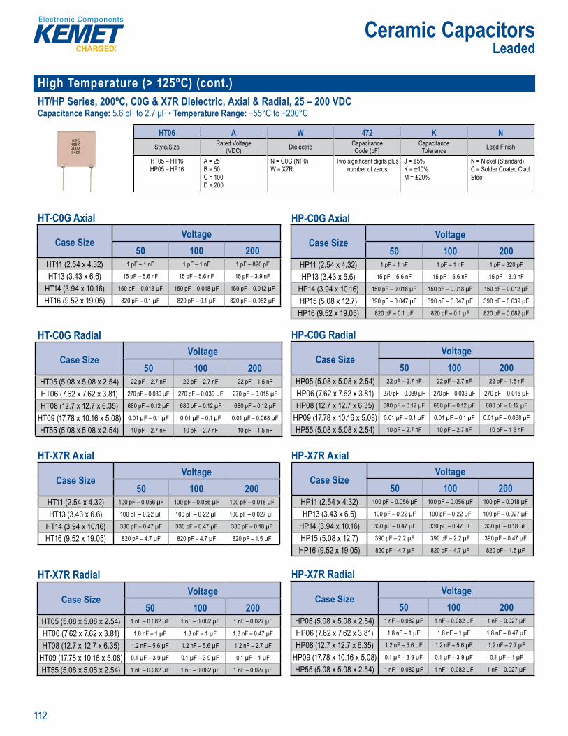
112
Ceramic CapacitorsLeaded
High Temperature (> 125ºC) (cont.)HT/HP Series, 200ºC, C0G & X7R Dielectric, Axial & Radial, 25 – 200 VDCCapacitance Range: 5.6 pF to 2.7 μF • Temperature Range: −55°C to +200°C
Ord ring nformation
HT06 A W 472 K NStyle/Size Rated Voltage
(VDC) Dielectric CapacitanceCode (pF)
CapacitanceTolerance Lead Finish
HT05 – HT16HP05 – HP16
A = 25B = 50C = 100D = 200
N = C0G (NP0)W = X7R
Two signifi cant digits plus number of zeros
J = ±5%K = ±10%M = ±20%
N = Nickel (Standard)C = Solder Coated Clad Steel
HT-C0G Axial
Case SizeVoltage
50 100 200HT11 (2.54 x 4.32) 1 pF – 1 nF 1 pF – 1 nF 1 pF – 820 pF
HT13 (3.43 x 6.6) 15 pF – 5.6 nF 15 pF – 5.6 nF 15 pF – 3.9 nF
HT14 (3.94 x 10.16) 150 pF – 0.018 µF 150 pF – 0.018 µF 150 pF – 0.012 µF
HT16 (9.52 x 19.05) 820 pF – 0.1 µF 820 pF – 0.1 µF 820 pF – 0.082 µF HT-C0G Radial
Case SizeVoltage
50 100 200HT05 (5.08 x 5.08 x 2.54) 22 pF – 2.7 nF 22 pF – 2.7 nF 22 pF – 1.5 nF
HT06 (7.62 x 7.62 x 3.81) 270 pF – 0.039 µF 270 pF – 0.039 µF 270 pF – 0.015 µF
HT08 (12.7 x 12.7 x 6.35) 680 pF – 0.12 µF 680 pF – 0.12 µF 680 pF – 0.12 µF
HT09 (17.78 x 10.16 x 5.08) 0.01 µF – 0.1 µF 0.01 µF – 0.1 µF 0.01 µF – 0.068 µF
HT55 (5.08 x 5.08 x 2.54) 10 pF – 2.7 nF 10 pF – 2.7 nF 10 pF – 1.5 nF HT-X7R Axial
Case SizeVoltage
50 100 200HT11 (2.54 x 4.32) 100 pF – 0.056 µF 100 pF – 0.056 µF 100 pF – 0.018 µF
HT13 (3.43 x 6.6) 100 pF – 0.22 µF 100 pF – 0 22 µF 100 pF – 0.027 µF
HT14 (3.94 x 10.16) 330 pF – 0.47 µF 330 pF – 0.47 µF 330 pF – 0.18 µF
HT16 (9.52 x 19.05) 820 pF – 4.7 µF 820 pF – 4.7 µF 820 pF – 1.5 µF
HT-X7R Radial
Case SizeVoltage
50 100 200HT05 (5.08 x 5.08 x 2.54) 1 nF – 0.082 µF 1 nF – 0.082 µF 1 nF – 0.027 µF
HT06 (7.62 x 7.62 x 3.81) 1.8 nF – 1 µF 1.8 nF – 1 µF 1.8 nF – 0.47 µF
HT08 (12.7 x 12.7 x 6.35) 1.2 nF – 5.6 µF 1.2 nF – 5.6 µF 1.2 nF – 2.7 µF
HT09 (17.78 x 10.16 x 5.08) 0.1 µF – 3 9 µF 0.1 µF – 3 9 µF 0.1 µF – 1 µF
HT55 (5.08 x 5.08 x 2.54) 1 nF – 0.082 µF 1 nF – 0.082 µF 1 nF – 0.027 µF
HP-C0G Axial
Case SizeVoltage
50 100 200HP11 (2.54 x 4.32) 1 pF – 1 nF 1 pF – 1 nF 1 pF – 820 pF
HP13 (3.43 x 6.6) 15 pF – 5.6 nF 15 pF – 5.6 nF 15 pF – 3.9 nF
HP14 (3.94 x 10.16) 150 pF – 0.018 µF 150 pF – 0.018 µF 150 pF – 0.012 µF
HP15 (5.08 x 12.7) 390 pF – 0.047 µF 390 pF – 0.047 µF 390 pF – 0.039 µF
HP16 (9.52 x 19.05) 820 pF – 0.1 µF 820 pF – 0.1 µF 820 pF – 0.082 µF
HP-C0G Radial
Case SizeVoltage
50 100 200HP05 (5.08 x 5.08 x 2.54) 22 pF – 2.7 nF 22 pF – 2.7 nF 22 pF – 1.5 nF
HP06 (7.62 x 7.62 x 3.81) 270 pF – 0.039 µF 270 pF – 0.039 µF 270 pF – 0.015 µF
HP08 (12.7 x 12.7 x 6.35) 680 pF – 0.12 µF 680 pF – 0.12 µF 680 pF – 0.12 µF
HP09 (17.78 x 10.16 x 5.08) 0.01 µF – 0.1 µF 0.01 µF – 0.1 µF 0.01 µF – 0.068 µF
HP55 (5.08 x 5.08 x 2.54) 10 pF – 2.7 nF 10 pF – 2.7 nF 10 pF – 1 5 nF
HP-X7R Axial
Case SizeVoltage
50 100 200HP11 (2.54 x 4.32) 100 pF – 0.056 µF 100 pF – 0.056 µF 100 pF – 0.018 µF
HP13 (3.43 x 6.6) 100 pF – 0.22 µF 100 pF – 0 22 µF 100 pF – 0.027 µF
HP14 (3.94 x 10.16) 330 pF – 0.47 µF 330 pF – 0.47 µF 330 pF – 0.18 µF
HP15 (5.08 x 12.7) 390 pF – 2.2 µF 390 pF – 2.2 µF 390 pF – 0.47 µF
HP16 (9.52 x 19.05) 820 pF – 4.7 µF 820 pF – 4.7 µF 820 pF – 1.5 µF HP-X7R Radial
Case SizeVoltage
50 100 200HP05 (5.08 x 5.08 x 2.54) 1 nF – 0.082 µF 1 nF – 0.082 µF 1 nF – 0.027 µF
HP06 (7.62 x 7.62 x 3.81) 1.8 nF – 1 µF 1.8 nF – 1 µF 1.8 nF – 0.47 µF
HP08 (12.7 x 12.7 x 6.35) 1.2 nF – 5.6 µF 1.2 nF – 5.6 µF 1.2 nF – 2.7 µF
HP09 (17.78 x 10.16 x 5.08) 0.1 µF – 3 9 µF 0.1 µF – 3 9 µF 0.1 µF – 1 µF
HP55 (5.08 x 5.08 x 2.54) 1 nF – 0.082 µF 1 nF – 0.082 µF 1 nF – 0.027 µF
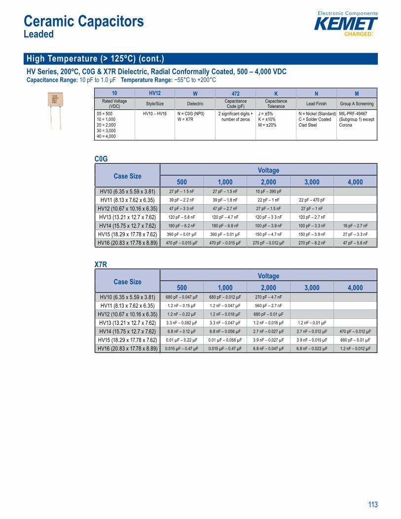
113
Ceramic CapacitorsLeaded
High Temperature (> 125ºC) (cont.)HV Series, 200ºC, C0G & X7R Dielectric, Radial Conformally Coated, 500 – 4,000 VDCCapacitance Range: 10 pF to 1.0 μF Temperature Range: −55°C to +200°C
Or e ng Information
10 HV12 W 472 K N MRated Voltage
(VDC) Style/Size Dielectric CapacitanceCode (pF)
CapacitanceTolerance Lead Finish Group A Screening
05 = 50010 = 1,00020 = 2,00030 = 3,00040 = 4,000
HV10 – HV16 N = C0G (NP0)W = X7R
2 signifi cant digits + number of zeros
J = ±5%K = ±10%M = ±20%
N = Nickel (Standard)C = Solder Coated Clad Steel
MIL-PRF-49467 (Subgroup 1) except Corona
C0G
Case SizeVoltage
500 1,000 2,000 3,000 4,000HV10 (6.35 x 5.59 x 3.81) 27 pF – 1 5 nF 27 pF – 1.5 nF 10 pF – 390 pF
HV11 (8.13 x 7.62 x 6.35) 39 pF – 2.2 nF 39 pF – 1.8 nF 22 pF – 1 nF 22 pF – 470 pF
HV12 (10.67 x 10.16 x 6.35) 47 pF – 3 3 nF 47 pF – 2.7 nF 27 pF – 1.5 nF 27 pF – 1 nF
HV13 (13.21 x 12.7 x 7.62) 120 pF – 5.6 nF 120 pF – 4.7 nF 120 pF – 3 3 nF 120 pF – 2.7 nF
HV14 (15.75 x 12.7 x 7.62) 180 pF – 8.2 nF 180 pF – 6.8 nF 100 pF – 3.9 nF 100 pF – 3.3 nF 18 pF – 2.7 nF
HV15 (18.29 x 17.78 x 7.62) 390 pF – 0.01 µF 390 pF – 0.01 µF 150 pF – 4.7 nF 150 pF – 3.9 nF 27 pF – 3.3 nF
HV16 (20.83 x 17.78 x 8.89) 470 pF – 0.015 µF 470 pF – 0.015 µF 270 pF – 0.012 µF 270 pF – 8.2 nF 47 pF – 5.6 nF
X7R
Case SizeVoltage
500 1,000 2,000 3,000 4,000HV10 (6.35 x 5.59 x 3.81) 680 pF – 0.047 µF 680 pF – 0.012 µF 270 pF – 4.7 nF
HV11 (8.13 x 7.62 x 6.35) 1.2 nF – 0.15 µF 1.2 nF – 0.047 µF 560 pF – 2.7 nF
HV12 (10.67 x 10.16 x 6.35) 1.2 nF – 0.22 µF 1.2 nF – 0.018 µF 680 pF – 0.01 µF
HV13 (13.21 x 12.7 x 7.62) 3.3 nF – 0.082 µF 3.3 nF – 0.047 µF 1.2 nF – 0.018 µF 1.2 nF – 0.01 µF
HV14 (15.75 x 12.7 x 7.62) 6.8 nF – 0.12 µF 6.8 nF – 0.056 µF 2.7 nF – 0.027 µF 2.7 nF – 0.012 µF 470 pF – 0.012 µF
HV15 (18.29 x 17.78 x 7.62) 0.01 µF – 0.22 µF 0.01 µF – 0.056 µF 3.9 nF – 0.027 µF 3 9 nF – 0.015 µF 680 pF – 0.01 µF
HV16 (20.83 x 17.78 x 8.89) 0.015 µF – 0.47 µF 0.015 µF – 0.47 µF 6.8 nF – 0.047 µF 6.8 nF – 0.022 µF 1.2 nF – 0.012 µF
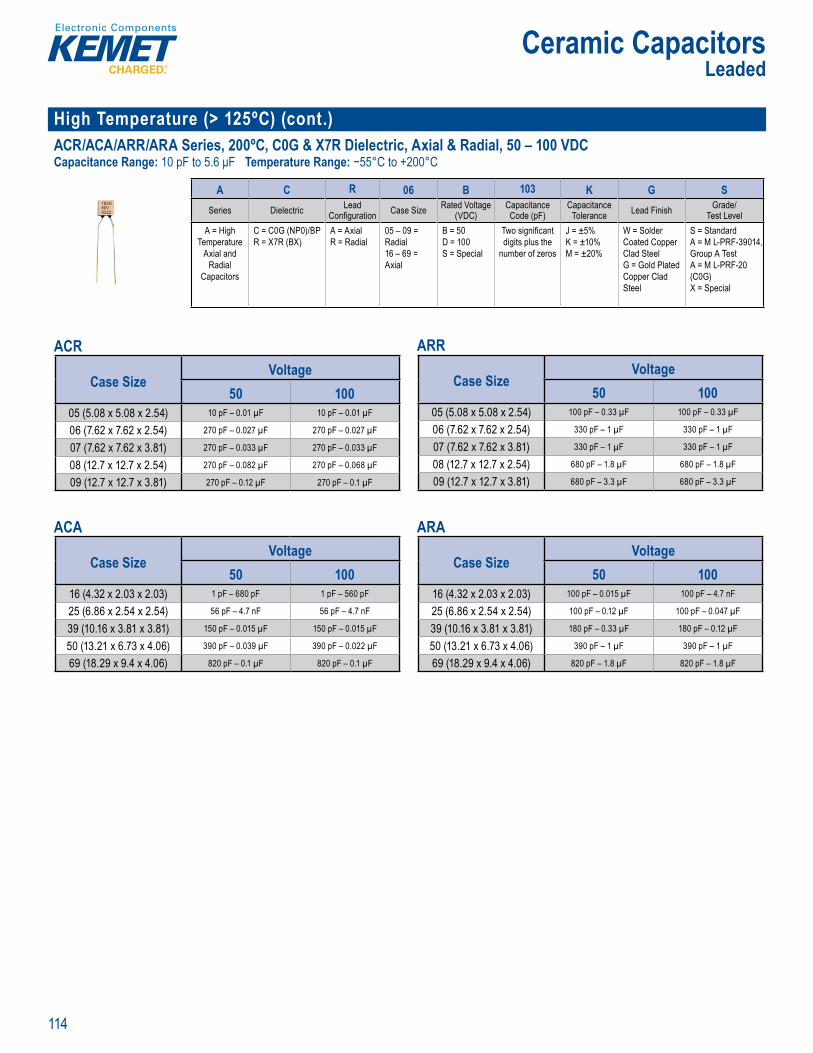
114
Ceramic CapacitorsLeaded
High Temperature (> 125ºC) (cont.)ACR/ACA/ARR/ARA Series, 200ºC, C0G & X7R Dielectric, Axial & Radial, 50 – 100 VDCCapacitance Range: 10 pF to 5.6 μF Temperature Range: −55°C to +200°C
Orde ng Information
A C R 06 B 103 K G SSeries Dielectric Lead
Confi guration Case Size Rated Voltage (VDC)
CapacitanceCode (pF)
CapacitanceTolerance Lead Finish Grade/
Test LevelA = High
Temperature Axial and
Radial Capacitors
C = C0G (NP0)/BPR = X7R (BX)
A = AxialR = Radial
05 – 09 = Radial16 – 69 = Axial
B = 50D = 100S = Special
Two signifi cant digits plus the
number of zeros
J = ±5%K = ±10%M = ±20%
W = Solder Coated Copper Clad SteelG = Gold Plated Copper Clad Steel
S = StandardA = M L-PRF-39014, Group A TestA = M L-PRF-20 (C0G)X = Special
ACR
Case SizeVoltage
50 10005 (5.08 x 5.08 x 2.54) 10 pF – 0.01 µF 10 pF – 0.01 µF
06 (7.62 x 7.62 x 2.54) 270 pF – 0.027 µF 270 pF – 0.027 µF
07 (7.62 x 7.62 x 3.81) 270 pF – 0.033 µF 270 pF – 0.033 µF
08 (12.7 x 12.7 x 2.54) 270 pF – 0.082 µF 270 pF – 0.068 µF
09 (12.7 x 12.7 x 3.81) 270 pF – 0.12 µF 270 pF – 0.1 µF
ACA
Case SizeVoltage
50 10016 (4.32 x 2.03 x 2.03) 1 pF – 680 pF 1 pF – 560 pF
25 (6.86 x 2.54 x 2.54) 56 pF – 4.7 nF 56 pF – 4.7 nF
39 (10.16 x 3.81 x 3.81) 150 pF – 0.015 µF 150 pF – 0.015 µF
50 (13.21 x 6.73 x 4.06) 390 pF – 0.039 µF 390 pF – 0.022 µF
69 (18.29 x 9.4 x 4.06) 820 pF – 0.1 µF 820 pF – 0.1 µF
ARR
Case SizeVoltage
50 10005 (5.08 x 5.08 x 2.54) 100 pF – 0.33 µF 100 pF – 0.33 µF
06 (7.62 x 7.62 x 2.54) 330 pF – 1 µF 330 pF – 1 µF
07 (7.62 x 7.62 x 3.81) 330 pF – 1 µF 330 pF – 1 µF
08 (12.7 x 12.7 x 2.54) 680 pF – 1.8 µF 680 pF – 1.8 µF
09 (12.7 x 12.7 x 3.81) 680 pF – 3.3 µF 680 pF – 3.3 µF
ARA
Case SizeVoltage
50 10016 (4.32 x 2.03 x 2.03) 100 pF – 0.015 µF 100 pF – 4.7 nF
25 (6.86 x 2.54 x 2.54) 100 pF – 0.12 µF 100 pF – 0.047 µF
39 (10.16 x 3.81 x 3.81) 180 pF – 0.33 µF 180 pF – 0.12 µF
50 (13.21 x 6.73 x 4.06) 390 pF – 1 µF 390 pF – 1 µF
69 (18.29 x 9.4 x 4.06) 820 pF – 1.8 µF 820 pF – 1.8 µF
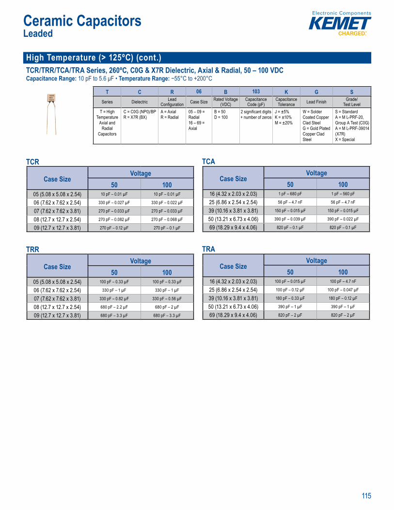
115
Ceramic CapacitorsLeaded
High Temperature (> 125ºC) (cont.)TCR/TRR/TCA/TRA Series, 260ºC, C0G & X7R Dielectric, Axial & Radial, 50 – 100 VDCCapacitance Range: 10 pF to 5.6 μF • Temperature Range: −55°C to +200°C
O derin Information
T C R 06 B 103 K G SSeries Dielectric Lead
Confi guration Case Size Rated Voltage (VDC)
CapacitanceCode (pF)
CapacitanceTolerance Lead Finish Grade/
Test LevelT = High
Temperature Axial and
Radial Capacitors
C = C0G (NP0)/BPR = X7R (BX)
A = AxialR = Radial
05 – 09 = Radial16 – 69 = Axial
B = 50D = 100
2 signifi cant digits + number of zeros
J = ±5%K = ±10%M = ±20%
W = Solder Coated Copper Clad SteelG = Gold Plated Copper Clad Steel
S = StandardA = M L-PRF-20, Group A Test (C0G)A = M L-PRF-39014 (X7R)X = Special
TCR
Case SizeVoltage
50 10005 (5.08 x 5.08 x 2.54) 10 pF – 0.01 µF 10 pF – 0.01 µF
06 (7.62 x 7.62 x 2.54) 330 pF – 0.027 µF 330 pF – 0.022 µF
07 (7.62 x 7.62 x 3.81) 270 pF – 0.033 µF 270 pF – 0.033 µF
08 (12.7 x 12.7 x 2.54) 270 pF – 0.082 µF 270 pF – 0.068 µF
09 (12.7 x 12.7 x 3.81) 270 pF – 0.12 µF 270 pF – 0.1 µF
TRR
Case SizeVoltage
50 10005 (5.08 x 5.08 x 2.54) 100 pF – 0.33 µF 100 pF – 0.33 µF
06 (7.62 x 7.62 x 2.54) 330 pF – 1 µF 330 pF – 1 µF
07 (7.62 x 7.62 x 3.81) 330 pF – 0.82 µF 330 pF – 0.56 µF
08 (12.7 x 12.7 x 2.54) 680 pF – 2.2 µF 680 pF – 2 µF
09 (12.7 x 12.7 x 3.81) 680 pF – 3.3 µF 680 pF – 3.3 µF
TCA
Case SizeVoltage
50 10016 (4.32 x 2.03 x 2.03) 1 pF – 680 pF 1 pF – 560 pF
25 (6.86 x 2.54 x 2.54) 56 pF – 4.7 nF 56 pF – 4.7 nF
39 (10.16 x 3.81 x 3.81) 150 pF – 0.015 µF 150 pF – 0.015 µF
50 (13.21 x 6.73 x 4.06) 390 pF – 0.039 µF 390 pF – 0.022 µF
69 (18.29 x 9.4 x 4.06) 820 pF – 0.1 µF 820 pF – 0.1 µF
TRA
Case SizeVoltage
50 10016 (4.32 x 2.03 x 2.03) 100 pF – 0.015 µF 100 pF – 4.7 nF
25 (6.86 x 2.54 x 2.54) 100 pF – 0.12 µF 100 pF – 0.047 µF
39 (10.16 x 3.81 x 3.81) 180 pF – 0.33 µF 180 pF – 0.12 µF
50 (13.21 x 6.73 x 4.06) 390 pF – 1 µF 390 pF – 1 µF
69 (18.29 x 9.4 x 4.06) 820 pF – 2 µF 820 pF – 2 µF
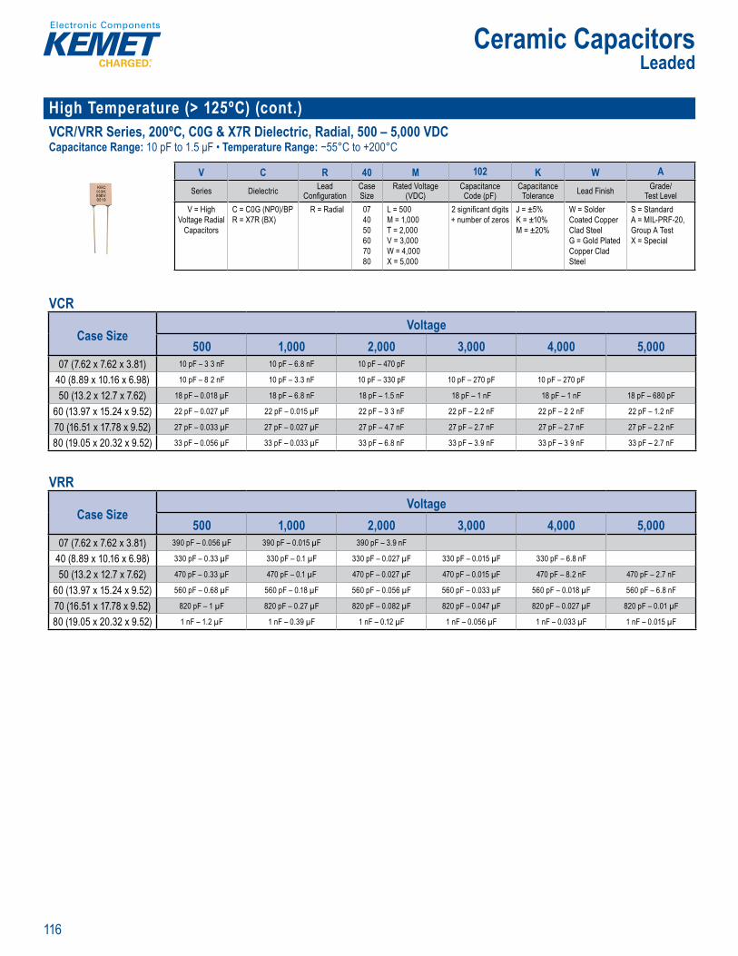
116
Ceramic CapacitorsLeaded
High Temperature (> 125ºC) (cont.)VCR/VRR Series, 200ºC, C0G & X7R Dielectric, Radial, 500 – 5,000 VDCCapacitance Range: 10 pF to 1.5 μF • Temperature Range: −55°C to +200°C
O derin Information
V C R 40 M 102 K W A
Series Dielectric Lead Confi guration
Case Size
Rated Voltage (VDC)
CapacitanceCode (pF)
CapacitanceTolerance Lead Finish Grade/
Test LevelV = High
Voltage Radial Capacitors
C = C0G (NP0)/BPR = X7R (BX)
R = Radial 074050607080
L = 500M = 1,000T = 2,000V = 3,000W = 4,000X = 5,000
2 signifi cant digits + number of zeros
J = ±5%K = ±10%M = ±20%
W = Solder Coated Copper Clad SteelG = Gold Plated Copper Clad Steel
S = StandardA = MIL-PRF-20, Group A TestX = Special
VCR
Case SizeVoltage
500 1,000 2,000 3,000 4,000 5,00007 (7.62 x 7.62 x 3.81) 10 pF – 3 3 nF 10 pF – 6.8 nF 10 pF – 470 pF
40 (8.89 x 10.16 x 6.98) 10 pF – 8 2 nF 10 pF – 3.3 nF 10 pF – 330 pF 10 pF – 270 pF 10 pF – 270 pF
50 (13.2 x 12.7 x 7.62) 18 pF – 0.018 µF 18 pF – 6.8 nF 18 pF – 1.5 nF 18 pF – 1 nF 18 pF – 1 nF 18 pF – 680 pF
60 (13.97 x 15.24 x 9.52) 22 pF – 0.027 µF 22 pF – 0.015 µF 22 pF – 3 3 nF 22 pF – 2.2 nF 22 pF – 2 2 nF 22 pF – 1.2 nF
70 (16.51 x 17.78 x 9.52) 27 pF – 0.033 µF 27 pF – 0.027 µF 27 pF – 4.7 nF 27 pF – 2.7 nF 27 pF – 2.7 nF 27 pF – 2.2 nF
80 (19.05 x 20.32 x 9.52) 33 pF – 0.056 µF 33 pF – 0.033 µF 33 pF – 6.8 nF 33 pF – 3.9 nF 33 pF – 3 9 nF 33 pF – 2.7 nF
VRR
Case SizeVoltage
500 1,000 2,000 3,000 4,000 5,00007 (7.62 x 7.62 x 3.81) 390 pF – 0.056 µF 390 pF – 0.015 µF 390 pF – 3.9 nF
40 (8.89 x 10.16 x 6.98) 330 pF – 0.33 µF 330 pF – 0.1 µF 330 pF – 0.027 µF 330 pF – 0.015 µF 330 pF – 6.8 nF
50 (13.2 x 12.7 x 7.62) 470 pF – 0.33 µF 470 pF – 0.1 µF 470 pF – 0.027 µF 470 pF – 0.015 µF 470 pF – 8.2 nF 470 pF – 2.7 nF
60 (13.97 x 15.24 x 9.52) 560 pF – 0.68 µF 560 pF – 0.18 µF 560 pF – 0.056 µF 560 pF – 0.033 µF 560 pF – 0.018 µF 560 pF – 6.8 nF
70 (16.51 x 17.78 x 9.52) 820 pF – 1 µF 820 pF – 0.27 µF 820 pF – 0.082 µF 820 pF – 0.047 µF 820 pF – 0.027 µF 820 pF – 0.01 µF
80 (19.05 x 20.32 x 9.52) 1 nF – 1.2 µF 1 nF – 0.39 µF 1 nF – 0.12 µF 1 nF – 0.056 µF 1 nF – 0.033 µF 1 nF – 0.015 µF
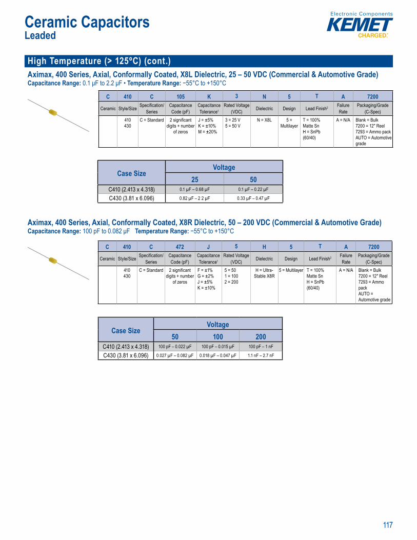
117
Ceramic CapacitorsLeaded
High Temperature (> 125ºC) (cont.)Aximax, 400 Series, Axial, Conformally Coated, X8L Dielectric, 25 – 50 VDC (Commercial & Automotive Grade)Capacitance Range: 0.1 μF to 2.2 μF • Temperature Range: −55°C to +150°C
c rcui s as wel as gener
O r ng n o mati
C 410 C 105 K 3 N 5 T A 7200
Ceramic Style/Size Specifi cation/Series
CapacitanceCode (pF)
CapacitanceTolerance1
Rated Voltage(VDC) Dielectric Design Lead Finish2 Failure
RatePackaging/Grade
(C-Spec)410430
C = Standard 2 signifi cant digits + number
of zeros
J = ±5%K = ±10%M = ±20%
3 = 25 V5 = 50 V
N = X8L 5 = Multilayer
T = 100% Matte Sn H = SnPb (60/40)
A = N/A Blank = Bulk7200 = 12" Reel7293 = Ammo packAUTO = Automotive grade
Case SizeVoltage
25 50C410 (2.413 x 4.318) 0.1 µF – 0.68 µF 0.1 µF – 0.22 µF
C430 (3.81 x 6.096) 0.82 µF – 2 2 µF 0.33 µF – 0.47 µF
Aximax, 400 Series, Axial, Conformally Coated, X8R Dielectric, 50 – 200 VDC (Commercial & Automotive Grade)Capacitance Range: 100 pF to 0.082 μF Temperature Range: −55°C to +150°C
Over iew
p ture d e ect o y temp ture a lica ons It offers ca a lity as convent ona X8R, b t thout he cap citanc o du o p o e ble R i its n
i i i t n h a h re a
s b c g c p t e nd larger footpri vices il to of e acitance it
c ith res t o temper e is li t -55
a a
These capac i cu t tion
St ndard 94V .
Ordering Information
C 410 C 472 J 5 H 5 T A 7200
Ceramic Style/Size Specifi cation/Series
CapacitanceCode (pF)
CapacitanceTolerance1
Rated Voltage (VDC) Dielectric Design Lead Finish2 Failure
RatePackaging/Grade
(C-Spec)410430
C = Standard 2 signifi cant digits + number
of zeros
F = ±1%G = ±2%J = ±5%K = ±10%
5 = 501 = 1002 = 200
H = Ultra-Stable X8R
5 = Multilayer T = 100% Matte Sn H = SnPb (60/40)
A = N/A Blank = Bulk7200 = 12" Reel 7293 = Ammo packAUTO = Automotive grade
Case SizeVoltage
50 100 200C410 (2.413 x 4.318) 100 pF – 0.022 µF 100 pF – 0.015 µF 100 pF – 1 nF
C430 (3.81 x 6.096) 0.027 µF – 0.082 µF 0.018 µF – 0.047 µF 1.1 nF – 2.7 nF
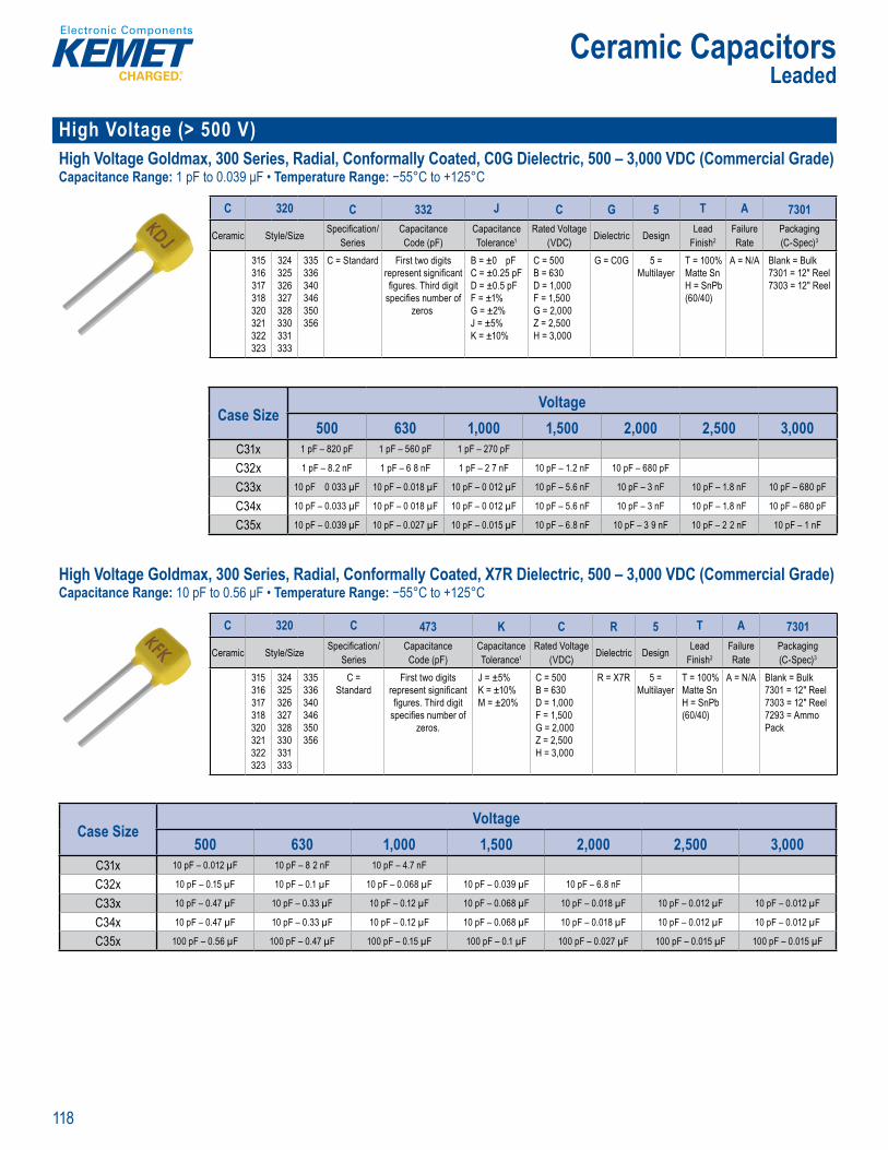
118
Ceramic CapacitorsLeaded
High Voltage (> 500 V) High Voltage Goldmax, 300 Series, Radial, Conformally Coated, C0G Dielectric, 500 – 3,000 VDC (Commercial Grade)Capacitance Range: 1 pF to 0.039 μF • Temperature Range: −55°C to +125°C
Order g nf rmation
C 320 C 332 J C G 5 T A 7301
Ceramic Style/Size Specifi cation/Series
CapacitanceCode (pF)
CapacitanceTolerance1
Rated Voltage (VDC) Dielectric Design Lead
Finish2Failure Rate
Packaging(C-Spec)3
315316317318320321322323
324325326327328330331333
335336340346350356
C = Standard First two digits represent signifi cant fi gures. Third digit
specifi es number of zeros
B = ±0 pFC = ±0.25 pFD = ±0.5 pFF = ±1%G = ±2%J = ±5%K = ±10%
C = 500B = 630D = 1,000F = 1,500G = 2,000Z = 2,500H = 3,000
G = C0G 5 = Multilayer
T = 100% Matte Sn H = SnPb (60/40)
A = N/A Blank = Bulk7301 = 12" Reel 7303 = 12" Reel
Case SizeVoltage
500 630 1,000 1,500 2,000 2,500 3,000C31x 1 pF – 820 pF 1 pF – 560 pF 1 pF – 270 pF
C32x 1 pF – 8.2 nF 1 pF – 6 8 nF 1 pF – 2 7 nF 10 pF – 1.2 nF 10 pF – 680 pF
C33x 10 pF 0 033 µF 10 pF – 0.018 µF 10 pF – 0 012 µF 10 pF – 5.6 nF 10 pF – 3 nF 10 pF – 1.8 nF 10 pF – 680 pF
C34x 10 pF – 0.033 µF 10 pF – 0 018 µF 10 pF – 0 012 µF 10 pF – 5.6 nF 10 pF – 3 nF 10 pF – 1.8 nF 10 pF – 680 pF
C35x 10 pF – 0.039 µF 10 pF – 0.027 µF 10 pF – 0.015 µF 10 pF – 6.8 nF 10 pF – 3 9 nF 10 pF – 2 2 nF 10 pF – 1 nF
High Voltage Goldmax, 300 Series, Radial, Conformally Coated, X7R Dielectric, 500 – 3,000 VDC (Commercial Grade)Capacitance Range: 10 pF to 0.56 μF • Temperature Range: −55°C to +125°C
r
s 3 Ser s H h olta e G max conform coated e er c c R dielectric feat ax m era re he Electron c d s-
nce EIA har ctr c a ss t e t " m fi c t o
ce mic
sp ti it t ce to pera ci ance
evi o nt i R i e cie d convent on se as sn bbe r fi lt rs in cations as swi ch n p er su p ies an l gh in
a asts ex epti e ance at igh fre uencie ha m choic o esig e wo d de n d on t lies, sed in in er sp c
Rad l Le
igh g o d a , 0 r , Con o y C a ed,X R Di ectr c 500 – 3,000 VDC (
O der ng nformation
C 320 C 473 K C R 5 T A 7301
Ceramic Style/Size Specifi cation/Series
CapacitanceCode (pF)
CapacitanceTolerance1
Rated Voltage (VDC) Dielectric Design Lead
Finish2Failure Rate
Packaging(C-Spec)3
315316317318320321322323
324325326327328330331333
335336340346350356
C = Standard
First two digits represent signifi cant fi gures. Third digit
specifi es number of zeros.
J = ±5%K = ±10%M = ±20%
C = 500B = 630D = 1,000F = 1,500G = 2,000Z = 2,500H = 3,000
R = X7R 5 = Multilayer
T = 100% Matte Sn H = SnPb (60/40)
A = N/A Blank = Bulk7301 = 12" Reel 7303 = 12" Reel 7293 = Ammo Pack
Case SizeVoltage
500 630 1,000 1,500 2,000 2,500 3,000C31x 10 pF – 0.012 µF 10 pF – 8 2 nF 10 pF – 4.7 nF
C32x 10 pF – 0.15 µF 10 pF – 0.1 µF 10 pF – 0.068 µF 10 pF – 0.039 µF 10 pF – 6.8 nF
C33x 10 pF – 0.47 µF 10 pF – 0.33 µF 10 pF – 0.12 µF 10 pF – 0.068 µF 10 pF – 0.018 µF 10 pF – 0.012 µF 10 pF – 0.012 µF
C34x 10 pF – 0.47 µF 10 pF – 0.33 µF 10 pF – 0.12 µF 10 pF – 0.068 µF 10 pF – 0.018 µF 10 pF – 0.012 µF 10 pF – 0.012 µF
C35x 100 pF – 0.56 µF 100 pF – 0.47 µF 100 pF – 0.15 µF 100 pF – 0.1 µF 100 pF – 0.027 µF 100 pF – 0.015 µF 100 pF – 0.015 µF

119
Ceramic CapacitorsLeaded
High Voltage (> 500 V) (cont.)High Voltage Goldmax, 600 Series, Radial, Conformally Coated, C0G Dielectric, 500 – 3,000 VDC (Commercial Grade)Capacitance Range: 12 pF to 0 1 μF • Temperature Range: −55°C to +125°C
• L ad spacing per MIL• ti t
O dering Information
C 627 C 224 K C G 5 T A 7301
Ceramic Style/Size Specifi cation/Series
CapacitanceCode (pF)
CapacitanceTolerance1
Rated Voltage(VDC) Dielectric Design Lead Finish2 Failure
RatePackaging(C-Spec)
617622623627628630631
637638640641642643647
648 657 658667668
C = Standard First two digits represent signifi cant
fi gures. Third d git specifi es
number of zeros.
K = ±10%M = ±20%Z = +80%, -20%
C = 500D = 1,000F = 1,500G = 2,000Z 2,500H = 3,000
G = C0G
5 = Multilayer
T = 100% Matte Sn H = SnPb (60/40)
A = N/A See “Packaging C-Spec Ordering
Options Table” below
Case SizeVoltage
500 1,000 1,500 2,000 2,500 3,000C61x 12 pF – 4.7 nF 12 pF – 2.2 nF 15 pF – 680 pF 15 pF – 680 pF 15 pF – 330 pF
C62x 22 pF – 0.018 µF 22 pF – 6.8 nF 22 pF – 3 3 nF 22 pF – 3.3 nF 22 pF – 1.2 nF
C63x 15 pF – 0.033 µF 15 pF – 0.015 µF 82 pF – 5.6 nF 15 pF – 5.6 nF 15 pF – 2.2 nF 15 pF – 2.2 nF
C64x 56 pF – 0 047 µF 56 pF – 0.047 µF 56 pF – 0.01 µF 56 pF – 4.7 nF
C65x 180 pF – 0 047 µF 180 pF – 0.047 µF 180 pF – 0.012 µF 180 pF – 5.6 nF
C66x 180 pF – 0.1 µF 180 pF – 0.068 µF 180 pF – 0.022 µF 180 pF – 8.2 nF
High Voltage Goldmax, 600 Series, Radial, Conformally Coated, X7R Dielectric, 500 – 3,000 VDC (Commercial Grade)Capacitance Range: 150 pF to 2.9 μF • Temperature Range: −55°C to +125°C
a e c L P F 67 rating re r e o - to +12 C and complia t tem ble d ec r c
Overvi w
KEM ’s S ri H h ta e o m n m ll
c em P ffe iel ct ese ca s feature a C maximu operating
red “t t e st b cs d t s n e (EIA) c acterizes X lect ic
s I t classifi c e am die ctr c for b pass d
ng p ic on discriminati a t b t i
These dev ces ffer w ea e c re t, e hibit lo SR at h gh e en bbe lt s in
i tc o er u es n lightin b ll s i rmance cies has made f desi orldwide In add tio a e w
e
Radia Leaded Mul ila
Order ng nformation
C 627 C 224 K C R 5 T A 7301
Ceramic Style/Size Specifi cation/Series
CapacitanceCode (pF)
CapacitanceTolerance1
Rated Voltage(VDC) Dielectric Design Lead Finish2 Failure
RatePackaging(C-Spec)
617622623627628630631
637638640641642643647
648 657 658667668
C = Standard First two digits represent signifi cant
fi gures. Third digit specifi es
number of zeros.
K = ±10%M = ±20%Z = +80%, -20%
C = 500D = 1,000F = 1,500G = 2,000Z = 2,500H = 3,000
R = X7R 5 = Multilayer
T = 100% Matte Sn H = SnPb (60/40)
A = N/A See “Packaging C-Spec Ordering
Options Table” below
Case SizeVoltage
500 1,000 1,500 2,000 2,500 3,000C61x 820 pF – 0.082 µF 820 pF – 0.022 µF 820 pF – 4.7 nF 820 pF – 4.7 nF
C62x 680 pF – 0.27 µF 680 pF – 0.1 µF 680 pF – 0.015 µF 680 pF – 0.015 µF 680 pF – 5.6 nF
C63x 150 pF – 0.56 µF 150 pF – 0.27 µF 150 pF – 0.033 µF 150 pF – 0.033 µF 150 pF – 0.015 µF 150 pF – 0.015 µF
C64x 680 pF – 1.2 µF 680 pF – 0.47 µF 680 pF – 0.1 µF 680 pF – 0.033 µF
C65x 2.2 nF – 1.8 µF 2.2 nF – 0.82 µF 2.2 nF – 0.12 µF 2.2 nF – 0.047 µF
C66x 2.2 nF – 2.7 µF 2.2 nF – 1 µF 2.2 nF – 0.18 µF 2.2 nF – 0.1 µF

120
Ceramic CapacitorsLeaded
High Voltage (> 500 V) (cont.)HV Series, C0G and X7R, Radial Conformally Coated, 500 – 10,000 VDCCapacitance Range: 12 pF to 5 6 μF • Temperature Range: −55°C to +125°C
O derin Information
10 HV23 N 102 K N MRated Voltage
(VDC) Style/Size Dielectric CapacitanceCode (pF)
CapacitanceTolerance Lead Finish Group A Screening
05 = 50010 = 1,00020 = 2,00030 = 3,00040 = 4,00050 = 5,00075 = 7,500100 = 10,000
HV20 – HV36 N = C0G (NP0)B = X7R
2 signifi cant digits + number of zeros
J = ±5%K = ±10%M = ±20%
N = Nickel C = Solder Coated Clad Steel (Standard)
MIL-PRF-49467 (Subgroup 1) except
Corona
C0G
Case SizeVoltage
500 1,000 2,000 3,000HV20 (6.35 x 5.59 x 5.08) 27 pF – 4.7 nF 27 pF – 1 5 nF 12 pF – 680 pF 12 pF – 470 pF
HV21 (8.13 x 7.11 x 6.35) 39 pF – 0.01 µF 39 pF – 0.01 µF 22 pF – 1 nF 22 pF – 560 pF
HV22 (9.4 x 7.62 x 6.35) 47 pF – 0.01 µF 47 pF – 3 9 nF 27 pF – 680 pF 27 pF – 680 pF
HV23 (11.94 x 10.16 x 6.86) 120 pF – 0.022 µF 120 pF – 0.018 µF 47 pF – 3.3 nF 47 pF – 1 nF
HV24 (14.48 x 12.7 x 6.86) 220 pF – 0.056 µF 220 pF – 0.033 µF 100 pF – 6.8 nF 100 pF – 3.9 nF
HV25 (17.02 x 15.24 x 6.86) 330 pF – 0.082 µF 220 pF – 0.047 µF 150 pF – 0.01 µF 150 pF – 6.8 nF
HV26 (19.56 x 18.29 x 6.86) 470 pF – 0.1 µF 220 pF – 0.068 µF 220 pF – 0.022 µF 220 pF – 8.2 nF
HV30 (11.43 x 5.59 x 5.08) 68 pF – 0.015 µF 68 pF – 4.7 nF 15 pF – 1 nF 15 pF – 390 pF
HV31 (13.97 x 7.11 x 6.35) 82 pF – 0.027 µF 82 pF – 0.012 µF 27 pF – 2.2 nF 27 pF – 1.2 nF
HV33 (21.59 x 10.16 x 6.86) 330 pF – 0.12 µF 220 pF – 0.068 µF 68 pF – 0.015 µF 68 pF – 4.7 nF
HV34 (26.67 x 12.7 x 6.86) 470 pF – 0.15 µF 220 pF – 0.056 µF 120 pF – 0.015 µF 120 pF – 5.6 nF
HV35 (31.75 x 15.24 x 6.86) 680 pF – 0.22 µF 220 pF – 0.1 µF 220 pF – 0.022 µF 220 pF – 0.015 µF
HV36 (36.83 x 18.29 x 6.86) 1 nF – 0.33 µF 1 nF – 0.15 µF 270 pF – 0.039 µF 270 pF – 0.018 µF
C0G (cont.)
Case SizeVoltage
4,000 5,000 7,000 10,000HV23 (11.94 x 10.16 x 6.86) 27 pF – 680 pF
HV24 (14.48 x 12.7 x 6.86) 18 pF – 1.5 nF 18 pF – 1 nF
HV25 (17.02 x 15.24 x 6.86) 27 pF – 2.7 nF 27 pF – 2.7 nF
HV26 (19.56 x 18.29 x 6.86) 47 pF – 3.9 nF 47 pF – 2.7 nF
HV30 (11.43 x 5.59 x 5.08) 10 pF – 220 pF
HV31 (13.97 x 7.11 x 6.35) 10 pF – 560 pF 10 pF – 390 pF
HV33 (21.59 x 10.16 x 6.86) 27 pF – 1.5 nF 27 pF – 1.2 nF 12 pF – 470 pF
HV34 (26.67 x 12.7 x 6.86) 47 pF – 3.3 nF 47 pF – 2.2 nF 18 pF – 1 nF 18 pF – 820 pF
HV35 (31.75 x 15.24 x 6.86) 82 pF – 5.6 nF 82 pF – 3 9 nF 33 pF – 1.8 nF 33 pF – 1.2 nF
HV36 (36.83 x 18.29 x 6.86) 120 pF – 8.2 nF 120 pF – 5.6 nF 56 pF – 2.7 nF 56 pF – 2.2 nF

121
Ceramic CapacitorsLeaded
High Voltage (> 500 V) (cont.)HV Series, C0G and X7R, Radial Conformally Coated, 500 – 10,000 VDC (cont.)Capacitance Range: 12 pF to 5.6 μF • Temperature Range: −55°C to +125°C
O derin Information
10 HV23 N 102 K N MRated Voltage
(VDC) Style/Size Dielectric CapacitanceCode (pF)
CapacitanceTolerance Lead Finish Group A Screening
05 = 50010 = 1,00020 = 2,00030 = 3,00040 = 4,00050 = 5,00075 = 7,500100 = 10,000
HV20 – HV36 N = C0G (NP0)B = X7R
2 signifi cant digits + number of zeros
J = ±5%K = ±10%M = ±20%
N = Nickel C = Solder Coated Clad Steel (Standard)
MIL-PRF-49467 (Subgroup 1) except
Corona
X7R
Case SizeVoltage
500 1,000 2,000 3,000HV20 (6.35 x 5.59 x 5.08) 680 pF – 0.082 µF 680 pF – 0.022 µF 270 pF – 4.7 nF
HV21 (8.13 x 7.11 x 6.35) 1.2 nF – 0.18 µF 1.2 nF – 0.068 µF 560 pF – 0.012 µF 560 pF – 3.9 nF
HV22 (9.4 x 7.62 x 6.35) 1.2 nF – 0.22 µF 1.2 nF – 0.1 µF 680 pF – 0.018 µF 680 pF – 5.6 nF
HV23 (11.94 x 10.16 x 6.86) 3.3 nF – 0.56 µF 3.3 nF – 0.27 µF 1.2 nF – 0.033 µF 1.2 nF – 0.015 µF
HV24 (14.48 x 12.7 x 6.86) 6.8 nF – 1.2 µF 6.8 nF – 0.47 µF 2.7 nF – 0.1 µF 2.7 nF – 0.033 µF
HV25 (17.02 x 15.24 x 6.86) 0.01 µF – 1.8 µF 0.01 µF – 0.68 µF 3 9 nF – 0.1 µF 3 9 nF – 0.039 µF
HV26 (19.56 x 18.29 x 6.86) 0.015 µF – 2 2 µF 0.015 µF – 0.82 µF 6.8 nF – 0.18 µF 6.8 nF – 0.082 µF
HV30 (11.43 x 5.59 x 5.08) 1.8 nF – 0.22 µF 1.8 nF – 0.056 µF 390 pF – 8 2 nF 390 pF – 2.2 nF
HV31 (13.97 x 7.11 x 6.35) 2.7 nF – 0.39 µF 2.7 nF – 0.15 µF 680 pF – 0.022 µF 680 pF – 8.2 nF
HV33 (21.59 x 10.16 x 6.86) 0.01 µF – 1.5 µF 0.01 µF – 0.68 µF 1.8 nF – 0.082 µF 1.8 nF – 0.027 µF
HV34 (26.67 x 12.7 x 6.86) 0.012 µF – 2 2 µF 0.012 µF – 1 µF 3.3 nF – 1 µF 3 3 nF – 0.056 µF
HV35 (31.75 x 15.24 x 6.86) 0.018 µF – 3 9 µF 0.018 µF – 1.5 µF 5.6 nF – 0 27 µF 5.6 nF – 0.082 µF
HV36 (36.83 x 18.29 x 6.86) 0.027 µF – 5.6 µF 0.027 µF – 2.2 µF 8 2 nF – 0 39 µF 8 2 nF – 0.15 µF
X7R (cont.)
Case SizeVoltage
4,000 5,000 7,000 10,000HV23 (11.94 x 10.16 x 6.86) 270 pF – 6.8 nF
HV24 (14.48 x 12.7 x 6.86) 470 pF – 0.01 µF 470 pF – 6.8 nF
HV25 (17.02 x 15.24 x 6.86) 680 pF – 0.015 µF 680 pF – 0.01 µF
HV26 (19.56 x 18.29 x 6.86) 1.2 nF – 0.027 µF 1 2 nF – 0.015 µF
HV30 (11.43 x 5.59 x 5.08) 150 pF – 1.2 nF
HV31 (13.97 x 7.11 x 6.35) 270 pF – 4.7 nF 270 pF – 2.7 nF
HV33 (21.59 x 10.16 x 6.86) 680 pF – 0.012 µF 680 pF – 8.2 nF 220 pF – 3.3 nF
HV34 (26.67 x 12.7 x 6.86) 1.2 nF – 0.027 µF 1.2 nF – 0.022 µF 470 pF – 6.8 nF 470 pF – 3.9 nF
HV35 (31.75 x 15.24 x 6.86) 2.2 nF – 0.047 µF 2 2 nF – 0.027 µF 820 pF – 0.01 µF 820 pF – 5.6 nF
HV36 (36.83 x 18.29 x 6.86) 3.3 nF – 0.068 µF 3 3 nF – 0.039 µF 1.2 nF – 0.033 µF 1.2 nF – 0.033 µF
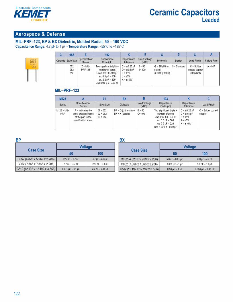
122
Ceramic CapacitorsLeaded
Aerospace & Defense MIL–PRF–123, BP & BX Dielectric, Molded Radial, 50 – 100 VDCCapacitance Range: 4.7 pF to 1 μF • Temperature Range: −55°C to +125°C
Orderin I ormation
C 052 Z 102 K 5 G 5 C A
Ceramic Style/Size Specifi cation/Series
CapacitanceCode (pF)
CapacitanceTolerance
Rated Voltage (VDC) Dielectric Design Lead Finish Failure Rate
052062512
Z = MIL-PRF-123
Two signifi cant digits + number of zeros
Use 9 for 1.0 - 9 9 pFex. 0.5 pF = 508ex. 2.2 pF = 229
Use 8 for 0 5 - 0.99 pF
C = ±0.25 pFD = ±0.5 pFF = ±1%J = ±5%K = ±10%
5 = 501= 100
G = BP (Ultra-stable)X = BX (Stable)
5 = Standard C = Solder coated copper
(standard)
A = N/A
MIL–PRF–123
d ri f rma i
C 052 Z 102 K 5 G 5 A
eramic Style Size Specifi cationSer es
Capacitanceode (pF)
apacitanceTolerance
ated Voltage (VDC) D e ectric Design Lead inish Failure ate
52062512
Z MILPRF 123
Two signifi cant digits number of ze os
Use fo 1 9 9 pex 5 pF 5e 2 2 pF = 229
Use o 5 99 p
± 25 pD = ±0 5 pFF ±1J ±5K = ±10%
5 51= 100
BP (Ultrastable)
BX (Stable)
5 Standa d C S lder ated copper (standard)
A A
MIL PRF– 23
M123 A 01 BX B 103 K CSeries Specifi cation/
Series Style/Size Dielectric Rated Voltage (VDC)
CapacitanceCode (pF)
CapacitanceTolerance Lead Finish
M123 = MIL-PRF
A = Indicates the latest characteristics
of the part in the specifi cation sheet.
01 = 05202 = 06203 = 512
BP = G (Ultra-stable)BX = X (Stable)
B = 50C= 100
Two signifi cant digits + number of zeros
Use 9 for 1.0 - 9.9 pFex. 0 5 pF = 508ex. 2 2 pF = 229
Use 8 for 0 5 - 0.99 pF
C = ±0 25 pFD = ±0 5 pFF = ±1%J = ±5%K = ±10%
C = Solder coated copper
BP
Case SizeVoltage
50 100C052 (4.826 x 5.969 x 2.286) 270 pF – 2.7 nF 4.7 pF – 240 pF
C062 (7.366 x 7.366 x 2.286) 2.7 nF – 4.7 nF 270 pF – 2.4 nF
C512 (12.192 x 12.192 x 3.556) 0.011 µF – 0.1 µF 2.7 nF – 0.01 µF
BX
Case SizeVoltage
50 100C052 (4.826 x 5.969 x 2.286) 5.6 nF – 0.01 µF 270 pF – 4.7 nF
C062 (7.366 x 7.366 x 2.286) 0.056 µF – 1 µF 5.6 nF – 0.1 µF
C512 (12.192 x 12.192 x 3.556) 0.56 µF – 1 µF 0.056 µF – 0.47 µF
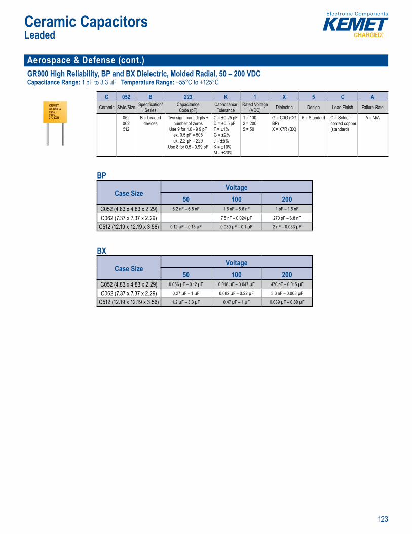
123
Ceramic CapacitorsLeaded
Aerospace & Defense (cont.)GR900 High Reliability, BP and BX Dielectric, Molded Radial, 50 – 200 VDCCapacitance Range: 1 pF to 3.3 μF Temperature Range: −55°C to +125°C
rderin Informa ion
C 052 B 223 K 1 X 5 C ACeramic Style/Size Specifi cation/
SeriesCapacitanceCode (pF)
CapacitanceTolerance
Rated Voltage (VDC) Dielectric Design Lead Finish Failure Rate
052062512
B = Leaded devices
Two signifi cant digits + number of zeros
Use 9 for 1.0 - 9 9 pFex. 0.5 pF = 508ex. 2.2 pF = 229
Use 8 for 0.5 - 0.99 pF
C = ±0.25 pFD = ±0.5 pFF = ±1%G = ±2%J = ±5%K = ±10%M = ±20%
1 = 1002 = 2005 = 50
G = C0G (CG, BP) X = X7R (BX)
5 = Standard C = Solder coated copper (standard)
A = N/A
BP
Case SizeVoltage
50 100 200C052 (4.83 x 4.83 x 2.29) 6.2 nF – 6.8 nF 1.6 nF – 5.6 nF 1 pF – 1.5 nF
C062 (7.37 x 7.37 x 2.29) 7 5 nF – 0.024 µF 270 pF – 6.8 nF
C512 (12.19 x 12.19 x 3.56) 0.12 µF – 0.15 µF 0.039 µF – 0.1 µF 2 nF – 0.033 µF
BX
Case SizeVoltage
50 100 200C052 (4.83 x 4.83 x 2.29) 0.056 µF – 0.12 µF 0.018 µF – 0.047 µF 470 pF – 0.015 µF
C062 (7.37 x 7.37 x 2.29) 0.27 µF – 1 µF 0.082 µF – 0.22 µF 3 3 nF – 0.068 µF
C512 (12.19 x 12.19 x 3.56) 1.2 µF – 3.3 µF 0.47 µF – 1 µF 0.039 µF – 0.39 µF
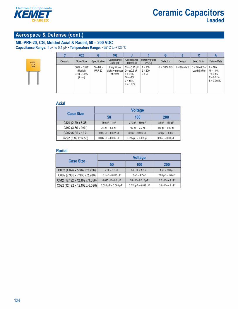
124
Ceramic CapacitorsLeaded
Aerospace & Defense (cont.)MIL-PRF-20, CG, Molded Axial & Radial, 50 – 200 VDCCapacitance Range: 1 pF to 0.1 μF • Temperature Range: −55°C to +125°C
Ord ri I formation
C 052 G 102 J 1 G 5 C ACeramic Style/Size Specifi cation Capacitance
Code (pF)Capacitance
ToleranceRated Voltage
(VDC) Dielectric Design Lead Finish Failure Rate
C052 – C522 (Radial)
C114 – C222 (Axial)
G – MIL-PRF-20
2 signifi cant digits + number
of zeros
C = ±0.25 pFD = ±0.5 pFF = ±1%G = ±2%J = ±5%K = ±10%
1 = 1002 = 2005 = 50
G = C0G, CG 5 = Standard C = 60/40 Tin/Lead (SnPb)
A = N/AM = 1.0%P = 0.1%R = 0.01%S = 0.001%
Axial
Case SizeVoltage
50 100 200C124 (2.29 x 6.35) 750 pF – 1 nF 270 pF – 680 pF 82 pF – 130 pF
C192 (3.56 x 9.91) 2.4 nF – 5.6 nF 750 pF – 2.2 nF 150 pF – 680 pF
C202 (6.35 x 12.7) 0.015 µF – 0.027 µF 3.9 nF – 0.012 µF 820 pF – 3 3 nF
C222 (8.89 x 17.53) 0.047 µF – 0.082 µF 0.015 µF – 0.039 µF 3.9 nF – 0.01 µF
Radial
Case SizeVoltage
50 100 200C052 (4.826 x 5.969 x 2.286) 2 nF – 3.3 nF 360 pF – 1.8 nF 1 pF – 330 pF
C062 (7.366 x 7.366 x 2.286) 5.1 nF – 0.018 µF 2 nF – 4.7 nF 360 pF – 1.8 nF
C512 (12.192 x 12.192 x 3.556) 0.015 µF – 0.1 µF 5.6 nF – 0.012 µF 2.2 nF – 4.7 nF
C522 (12.192 x 12.192 x 6.096) 0.056 µF – 0.068 µF 0.015 µF – 0.018 µF 3.9 nF – 4.7 nF
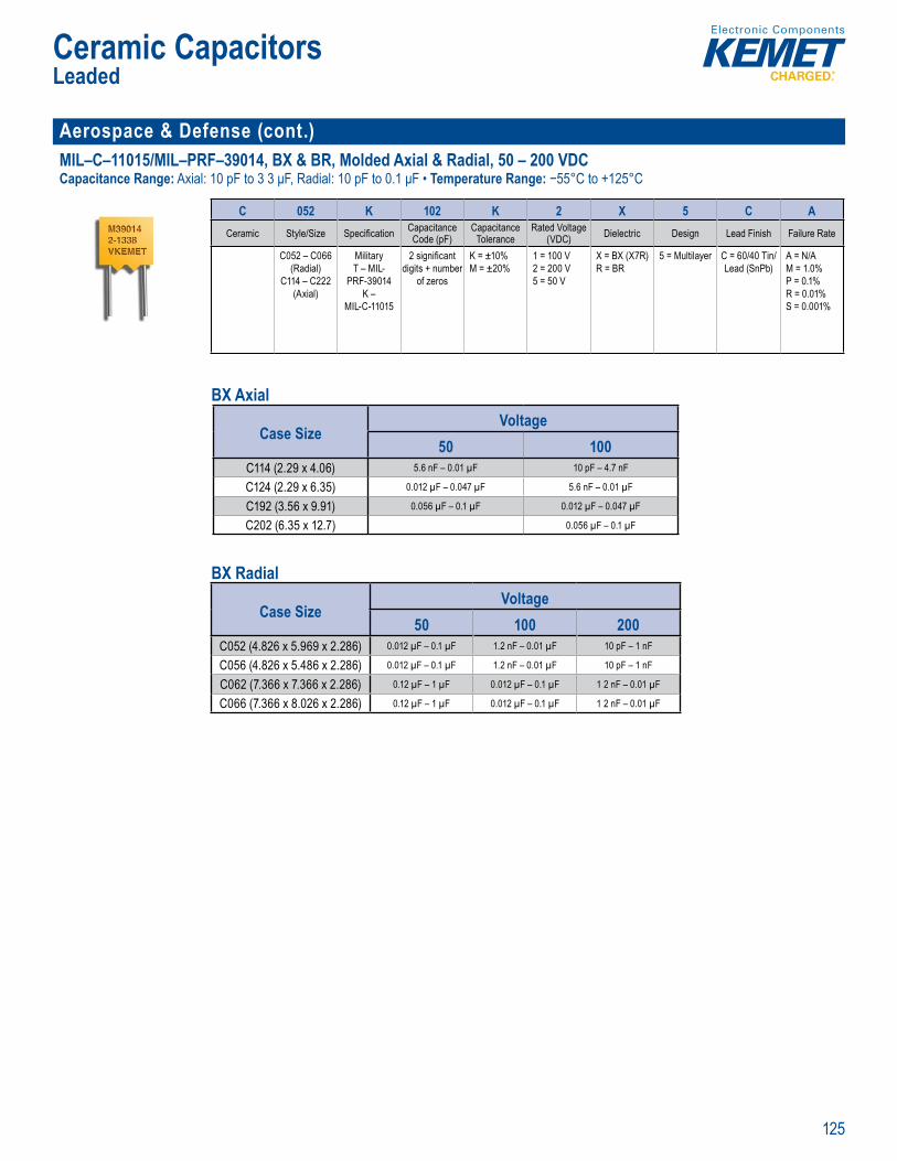
125
Ceramic CapacitorsLeaded
Aerospace & Defense (cont.)MIL–C–11015/MIL–PRF–39014, BX & BR, Molded Axial & Radial, 50 – 200 VDCCapacitance Range: Axial: 10 pF to 3 3 μF, Radial: 10 pF to 0.1 μF • Temperature Range: −55°C to +125°C
Ordering I formatio
C 052 K 102 K 2 X 5 C ACeramic Style/Size Specifi cation Capacitance
Code (pF)Capacitance
ToleranceRated Voltage
(VDC) Dielectric Design Lead Finish Failure Rate
C052 – C066(Radial)
C114 – C222(Axial)
MilitaryT – MIL-
PRF-39014K –
MIL-C-11015
2 signifi cant digits + number
of zeros
K = ±10%M = ±20%
1 = 100 V2 = 200 V5 = 50 V
X = BX (X7R)R = BR
5 = Multilayer C = 60/40 Tin/Lead (SnPb)
A = N/AM = 1.0%P = 0.1%R = 0.01%S = 0.001%
BX Axial
Case SizeVoltage
50 100C114 (2.29 x 4.06) 5.6 nF – 0.01 µF 10 pF – 4.7 nF
C124 (2.29 x 6.35) 0.012 µF – 0.047 µF 5.6 nF – 0.01 µF
C192 (3.56 x 9.91) 0.056 µF – 0.1 µF 0.012 µF – 0.047 µF
C202 (6.35 x 12.7) 0.056 µF – 0.1 µF
BX Radial
Case SizeVoltage
50 100 200C052 (4.826 x 5.969 x 2.286) 0.012 µF – 0.1 µF 1.2 nF – 0.01 µF 10 pF – 1 nF
C056 (4.826 x 5.486 x 2.286) 0.012 µF – 0.1 µF 1.2 nF – 0.01 µF 10 pF – 1 nF
C062 (7.366 x 7.366 x 2.286) 0.12 µF – 1 µF 0.012 µF – 0.1 µF 1 2 nF – 0.01 µF
C066 (7.366 x 8.026 x 2.286) 0.12 µF – 1 µF 0.012 µF – 0.1 µF 1 2 nF – 0.01 µF
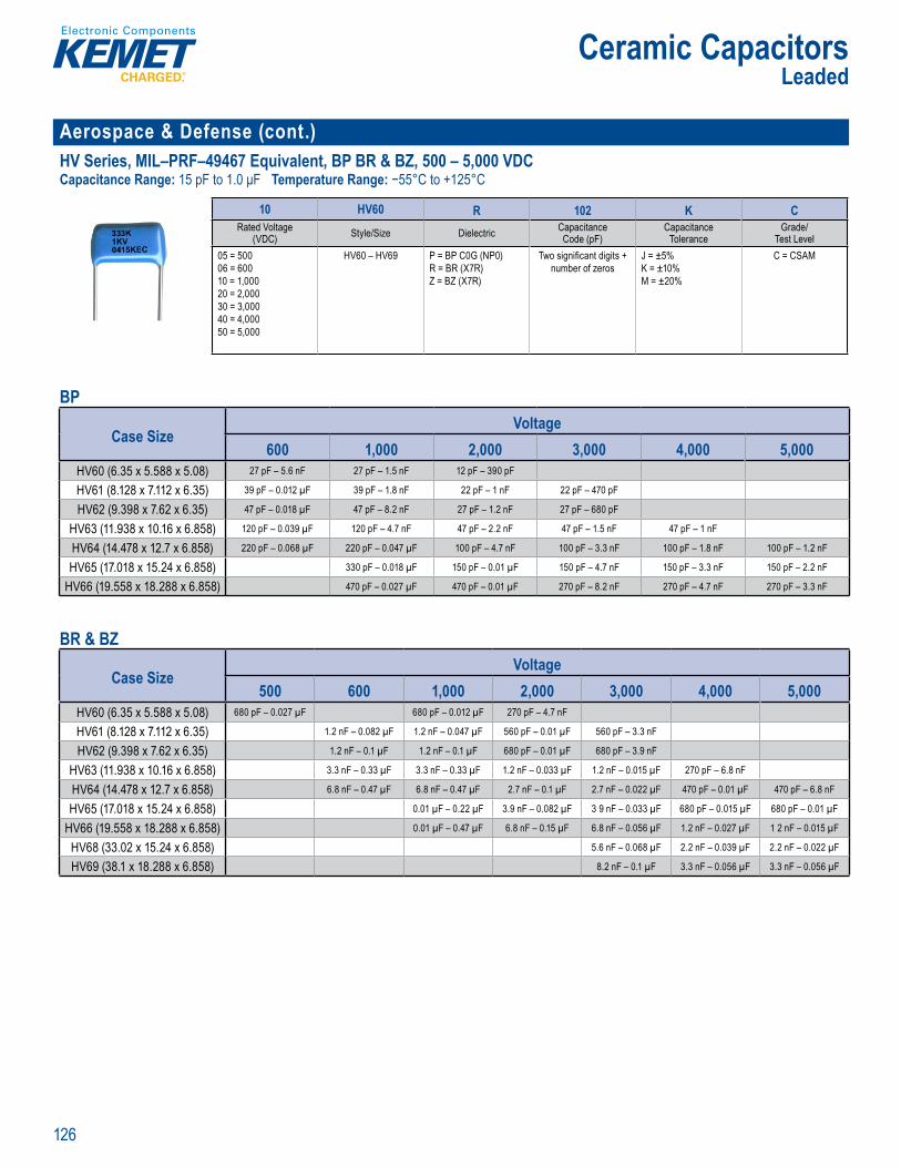
126
Ceramic CapacitorsLeaded
Aerospace & Defense (cont.)HV Series, MIL–PRF–49467 Equivalent, BP BR & BZ, 500 – 5,000 VDCCapacitance Range: 15 pF to 1.0 μF Temperature Range: −55°C to +125°C
Or e ng Information
10 HV60 R 102 K CRated Voltage
(VDC) Style/Size Dielectric CapacitanceCode (pF)
CapacitanceTolerance
Grade/Test Level
05 = 50006 = 60010 = 1,00020 = 2,00030 = 3,00040 = 4,00050 = 5,000
HV60 – HV69 P = BP C0G (NP0)R = BR (X7R)Z = BZ (X7R)
Two signifi cant digits + number of zeros
J = ±5%K = ±10%M = ±20%
C = CSAM
BP
Case SizeVoltage
600 1,000 2,000 3,000 4,000 5,000HV60 (6.35 x 5.588 x 5.08) 27 pF – 5.6 nF 27 pF – 1.5 nF 12 pF – 390 pF
HV61 (8.128 x 7.112 x 6.35) 39 pF – 0.012 µF 39 pF – 1.8 nF 22 pF – 1 nF 22 pF – 470 pF
HV62 (9.398 x 7.62 x 6.35) 47 pF – 0.018 µF 47 pF – 8.2 nF 27 pF – 1.2 nF 27 pF – 680 pF
HV63 (11.938 x 10.16 x 6.858) 120 pF – 0.039 µF 120 pF – 4.7 nF 47 pF – 2.2 nF 47 pF – 1.5 nF 47 pF – 1 nF
HV64 (14.478 x 12.7 x 6.858) 220 pF – 0.068 µF 220 pF – 0.047 µF 100 pF – 4.7 nF 100 pF – 3.3 nF 100 pF – 1.8 nF 100 pF – 1.2 nF
HV65 (17.018 x 15.24 x 6.858) 330 pF – 0.018 µF 150 pF – 0.01 µF 150 pF – 4.7 nF 150 pF – 3.3 nF 150 pF – 2.2 nF
HV66 (19.558 x 18.288 x 6.858) 470 pF – 0.027 µF 470 pF – 0.01 µF 270 pF – 8.2 nF 270 pF – 4.7 nF 270 pF – 3.3 nF
BR & BZ
Case SizeVoltage
500 600 1,000 2,000 3,000 4,000 5,000HV60 (6.35 x 5.588 x 5.08) 680 pF – 0.027 µF 680 pF – 0.012 µF 270 pF – 4.7 nF
HV61 (8.128 x 7.112 x 6.35) 1.2 nF – 0.082 µF 1.2 nF – 0.047 µF 560 pF – 0.01 µF 560 pF – 3.3 nF
HV62 (9.398 x 7.62 x 6.35) 1.2 nF – 0.1 µF 1.2 nF – 0.1 µF 680 pF – 0.01 µF 680 pF – 3.9 nF
HV63 (11.938 x 10.16 x 6.858) 3.3 nF – 0.33 µF 3.3 nF – 0.33 µF 1.2 nF – 0.033 µF 1.2 nF – 0.015 µF 270 pF – 6.8 nF
HV64 (14.478 x 12.7 x 6.858) 6.8 nF – 0.47 µF 6.8 nF – 0.47 µF 2.7 nF – 0.1 µF 2.7 nF – 0.022 µF 470 pF – 0.01 µF 470 pF – 6.8 nF
HV65 (17.018 x 15.24 x 6.858) 0.01 µF – 0.22 µF 3.9 nF – 0.082 µF 3 9 nF – 0.033 µF 680 pF – 0.015 µF 680 pF – 0.01 µF
HV66 (19.558 x 18.288 x 6.858) 0.01 µF – 0.47 µF 6.8 nF – 0.15 µF 6.8 nF – 0.056 µF 1.2 nF – 0.027 µF 1 2 nF – 0.015 µF
HV68 (33.02 x 15.24 x 6.858) 5.6 nF – 0.068 µF 2.2 nF – 0.039 µF 2.2 nF – 0.022 µF
HV69 (38.1 x 18.288 x 6.858) 8.2 nF – 0.1 µF 3.3 nF – 0.056 µF 3.3 nF – 0.056 µF
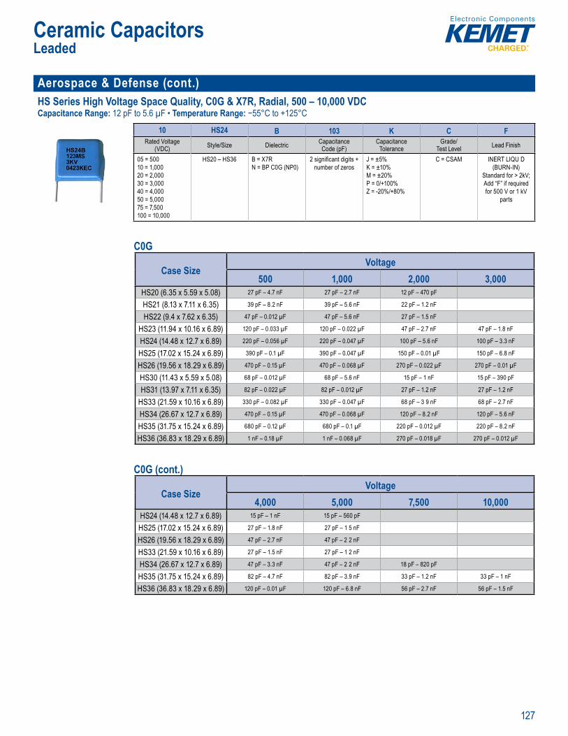
127
Ceramic CapacitorsLeaded
Aerospace & Defense (cont.)HS Series High Voltage Space Quality, C0G & X7R, Radial, 500 – 10,000 VDCCapacitance Range: 12 pF to 5.6 µF • Temperature Range: −55°C to +125°C
O de In o mat
10 HS24 B 103 K C FRated Voltage
(VDC) Style/Size Dielectric CapacitanceCode (pF)
CapacitanceTolerance
Grade/Test Level Lead Finish
05 = 50010 = 1,00020 = 2,00030 = 3,00040 = 4,00050 = 5,00075 = 7,500100 = 10,000
HS20 – HS36 B = X7RN = BP C0G (NP0)
2 signifi cant digits + number of zeros
J = ±5%K = ±10%M = ±20%P = 0/+100%Z = -20%/+80%
C = CSAM INERT LIQU D (BURN-IN)
Standard for > 2kV;Add “F” if requiredfor 500 V or 1 kV
parts
C0G
Case SizeVoltage
500 1,000 2,000 3,000HS20 (6.35 x 5.59 x 5.08) 27 pF – 4.7 nF 27 pF – 2.7 nF 12 pF – 470 pF
HS21 (8.13 x 7.11 x 6.35) 39 pF – 8.2 nF 39 pF – 5.6 nF 22 pF – 1.2 nF
HS22 (9.4 x 7.62 x 6.35) 47 pF – 0.012 µF 47 pF – 5.6 nF 27 pF – 1.5 nF
HS23 (11.94 x 10.16 x 6.89) 120 pF – 0.033 µF 120 pF – 0.022 µF 47 pF – 2.7 nF 47 pF – 1.8 nF
HS24 (14.48 x 12.7 x 6.89) 220 pF – 0.056 µF 220 pF – 0.047 µF 100 pF – 5.6 nF 100 pF – 3.3 nF
HS25 (17.02 x 15.24 x 6.89) 390 pF – 0.1 µF 390 pF – 0.047 µF 150 pF – 0.01 µF 150 pF – 6.8 nF
HS26 (19.56 x 18.29 x 6.89) 470 pF – 0.15 µF 470 pF – 0.068 µF 270 pF – 0.022 µF 270 pF – 0.01 µF
HS30 (11.43 x 5.59 x 5.08) 68 pF – 0.012 µF 68 pF – 5.6 nF 15 pF – 1 nF 15 pF – 390 pF
HS31 (13.97 x 7.11 x 6.35) 82 pF – 0.022 µF 82 pF – 0.012 µF 27 pF – 1.2 nF 27 pF – 1.2 nF
HS33 (21.59 x 10.16 x 6.89) 330 pF – 0.082 µF 330 pF – 0.047 µF 68 pF – 3 9 nF 68 pF – 2.7 nF
HS34 (26.67 x 12.7 x 6.89) 470 pF – 0.15 µF 470 pF – 0.068 µF 120 pF – 8.2 nF 120 pF – 5.6 nF
HS35 (31.75 x 15.24 x 6.89) 680 pF – 0.12 µF 680 pF – 0.1 µF 220 pF – 0.012 µF 220 pF – 8.2 nF
HS36 (36.83 x 18.29 x 6.89) 1 nF – 0.18 µF 1 nF – 0.068 µF 270 pF – 0.018 µF 270 pF – 0.012 µF
C0G (cont.)
Case SizeVoltage
4,000 5,000 7,500 10,000HS24 (14.48 x 12.7 x 6.89) 15 pF – 1 nF 15 pF – 560 pF
HS25 (17.02 x 15.24 x 6.89) 27 pF – 1.8 nF 27 pF – 1 5 nF
HS26 (19.56 x 18.29 x 6.89) 47 pF – 2.7 nF 47 pF – 2 2 nF
HS33 (21.59 x 10.16 x 6.89) 27 pF – 1.5 nF 27 pF – 1 2 nF
HS34 (26.67 x 12.7 x 6.89) 47 pF – 3.3 nF 47 pF – 2 2 nF 18 pF – 820 pF
HS35 (31.75 x 15.24 x 6.89) 82 pF – 4.7 nF 82 pF – 3.9 nF 33 pF – 1.2 nF 33 pF – 1 nF
HS36 (36.83 x 18.29 x 6.89) 120 pF – 0.01 µF 120 pF – 6.8 nF 56 pF – 2.7 nF 56 pF – 1.5 nF
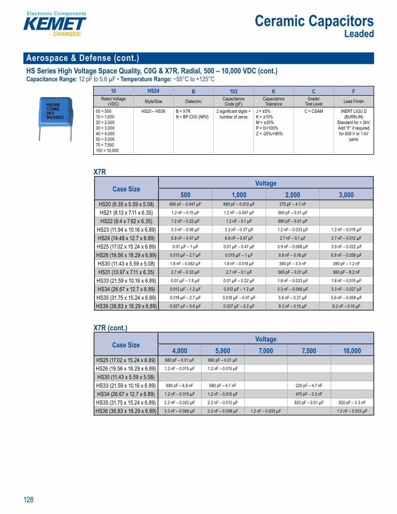
128
Ceramic CapacitorsLeaded
Aerospace & Defense (cont.)HS Series High Voltage Space Quality, C0G & X7R, Radial, 500 – 10,000 VDC (cont.)Capacitance Range: 12 pF to 5.6 µF • Temperature Range: −55°C to +125°C
O de In o mat
10 HS24 B 103 K C FRated Voltage
(VDC) Style/Size Dielectric CapacitanceCode (pF)
CapacitanceTolerance
Grade/Test Level Lead Finish
05 = 50010 = 1,00020 = 2,00030 = 3,00040 = 4,00050 = 5,00075 = 7,500100 = 10,000
HS20 – HS36 B = X7RN = BP C0G (NP0)
2 signifi cant digits + number of zeros
J = ±5%K = ±10%M = ±20%P = 0/+100%Z = -20%/+80%
C = CSAM INERT LIQU D (BURN-IN)
Standard for > 2kV;Add “F” if requiredfor 500 V or 1 kV
parts
X7R
Case SizeVoltage
500 1,000 2,000 3,000HS20 (6.35 x 5.59 x 5.08) 680 pF – 0.047 µF 680 pF – 0.012 µF 270 pF – 4.7 nF
HS21 (8.13 x 7.11 x 6.35) 1.2 nF – 0.15 µF 1.2 nF – 0.047 µF 560 pF – 0.01 µF
HS22 (9.4 x 7.62 x 6.35) 1 2 nF – 0.22 µF 1.2 nF – 0.1 µF 680 pF – 0.01 µF
HS23 (11.94 x 10.16 x 6.89) 3.3 nF – 0.56 µF 3 3 nF – 0 27 µF 1.2 nF – 0.033 µF 1.2 nF – 0.015 µF
HS24 (14.48 x 12.7 x 6.89) 6.8 nF – 0.47 µF 6.8 nF – 0.47 µF 2.7 nF – 0.1 µF 2.7 nF – 0.012 µF
HS25 (17.02 x 15.24 x 6.89) 0.01 µF – 1 µF 0.01 µF – 0.47 µF 3 9 nF – 0.068 µF 3.9 nF – 0.022 µF
HS26 (19.56 x 18.29 x 6.89) 0.015 µF – 2.7 µF 0.015 µF – 1 µF 6.8 nF – 0.18 µF 6.8 nF – 0.056 µF
HS30 (11.43 x 5.59 x 5.08) 1.8 nF – 0.082 µF 1.8 nF – 0.018 µF 390 pF – 3.3 nF 390 pF – 1.2 nF
HS31 (13.97 x 7.11 x 6.35) 2.7 nF – 0 33 µF 2.7 nF – 0.1 µF 560 pF – 0.01 µF 560 pF – 8.2 nF
HS33 (21.59 x 10.16 x 6.89) 0.01 µF – 1.5 µF 0.01 µF – 0.22 µF 1.8 nF – 0.033 µF 1.8 nF – 0.015 µF
HS34 (26.67 x 12.7 x 6.89) 0.012 µF – 1.2 µF 0.012 µF – 1 2 µF 3 3 nF – 0.068 µF 3.3 nF – 0.027 µF
HS35 (31.75 x 15.24 x 6.89) 0.018 µF – 2.7 µF 0.018 µF – 0.47 µF 5.6 nF – 0.27 µF 5.6 nF – 0.068 µF
HS36 (36.83 x 18.29 x 6.89) 0.027 µF – 5.6 µF 0.027 µF – 2.2 µF 8 2 nF – 0.15 µF 8.2 nF – 0.15 µF
X7R (cont.)
Case SizeVoltage
4,000 5,000 7,000 7,500 10,000HS25 (17.02 x 15.24 x 6.89) 680 pF – 0.01 µF 680 pF – 0.01 µF
HS26 (19.56 x 18.29 x 6.89) 1.2 nF – 0.015 µF 1.2 nF – 0.015 µF
HS30 (11.43 x 5.59 x 5.08)HS33 (21.59 x 10.16 x 6.89) 680 pF – 6.8 nF 680 pF – 4.7 nF 220 pF – 4.7 nF
HS34 (26.67 x 12.7 x 6.89) 1.2 nF – 0.015 µF 1.2 nF – 0.015 µF 470 pF – 3.3 nF
HS35 (31.75 x 15.24 x 6.89) 2.2 nF – 0.022 µF 2.2 nF – 0.012 µF 820 pF – 0.01 µF 820 pF – 3 3 nF
HS36 (36.83 x 18.29 x 6.89) 3.3 nF – 0.068 µF 3.3 nF – 0.039 µF 1.2 nF – 0.033 µF 1.2 nF – 0.033 µF
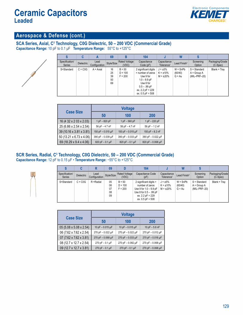
129
Ceramic CapacitorsLeaded
Aerospace & Defense (cont.)SCA Series, Axial, C3 Technology, C0G Dielectric, 50 – 200 VDC (Commercial Grade)Capacitance Range: 10 pF to 0.1 μF Temperature Range: 55°C to +125°C
P op ietary and ro us 55°C to 125°C per
Orde ng Information
S C A 69 B 104 J W SSpecifi cation/
Series Dielectric Lead Confi guration Style/Size Rated Voltage
(VDC)CapacitanceCode (pF)
CapacitanceTolerance1 Lead Finish2 Screening
OptionPackaging/Grade
(C-Spec)S=Standard C = C0G A = Axial 16
25395069
B = 50D = 100F = 200
2 signifi cant digits + number of zeros
Use 9 for 1.0 – 9.9 pF
Use 8 for 0.5 – .99 pF
ex. 2.2 pF = 229ex. 0.5 pF = 508
J = ±5%K = ±10%M = ±20%
W = SnPb (60/40)G = Au
S = StandardA = Group A (MIL–PRF–20)
Blank = Tray
Case SizeVoltage
50 100 20016 (4 32 x 2 03 x 2.03) 1 pF – 820 pF 1 pF – 560 pF 1 pF – 220 pF
25 (6.86 x 2.54 x 2.54) 56 pF – 4 7 nF 56 pF – 4.7 nF 56 pF – 1 2 nF
39 (10.16 x 3.81 x 3.81) 150 pF – 0.015 µF 150 pF – 0.015 µF 150 pF – 8.2 nF
50 (13.21 x 6.73 x 4.06) 390 pF – 0.039 µF 390 pF – 0.033 µF 390 pF – 0.022 µF
69 (18.29 x 9.4 x 4.06) 820 pF – 0.1 µF 820 pF – 0.1 µF 820 pF – 0.068 µF
SCR Series, Radial, C3 Technology, C0G Dielectric, 50 – 200 VDC (Commercial Grade)Capacitance Range: 12 pF to 0.15 μF • Temperature Range: −55°C to +125°C
encap ulated gy 00" a 0 400 e d g 5 °C to + 5 C ope a mpe tu e r D vo ta e r ting f 5 0 a 00 e o g r 8
r roug ol c c e c aci or in C G dielectric fe ture p oprietary Cer mic C e Ca citor (C3) Te h log nd are esig e to meet the n eds f criti al
y s a i
nnection to e Multila eram apacitor MLCC) y
t o a x he mpare
e
e c i t and is ons d red “sta
r c r o Q and lity of cap tance char risti s r uired C0G
g p l b s egligi c ng i p ita ce
ambi mpe ature apac t hange s limi C ro
er , 50 200 VDC
Ordering Informati n
S C R 09 D 184 J W SSpecifi cation/
Series Dielectric Lead Confi guration Style/Size Rated Voltage
(VDC)Capacitance Code
(pF)CapacitanceTolerance1 Lead Finish2 Screening
OptionPackaging/Grade
(C-Spec)S=Standard C = C0G R =Radial 05
06070809
B = 50D = 100F = 200
2 signifi cant digits + number of zeros
Use 9 for 1.0 – 9.9 pFUse 8 for 0.5 – .99 pF
ex. 2.2 pF = 229ex. 0.5 pF = 508
J = ±5%K = ±10%M = ±20%
W = SnPb (60/40)G = Au
S = StandardA = Group A(MIL–PRF–20)
Blank = Tray
Case SizeVoltage
50 100 20005 (5.08 x 5.08 x 2.54) 10 pF – 0.015 µF 10 pF – 0.015 µF 10 pF – 5.6 nF
06 (7.62 x 7.62 x 2.54) 270 pF – 0.022 µF 270 pF – 0.022 µF 270 pF – 0.012 µF
07 (7.62 x 7.62 x 3.81) 270 pF – 0.068 µF 270 pF – 0.033 µF 270 pF – 0.018 µF
08 (12.7 x 12.7 x 2.54) 270 pF – 0.1 µF 270 pF – 0.082 µF 270 pF – 0.068 µF
09 (12.7 x 12.7 x 3.81) 270 pF – 0.1 µF 270 pF – 0.1 µF 270 pF – 0.068 µF
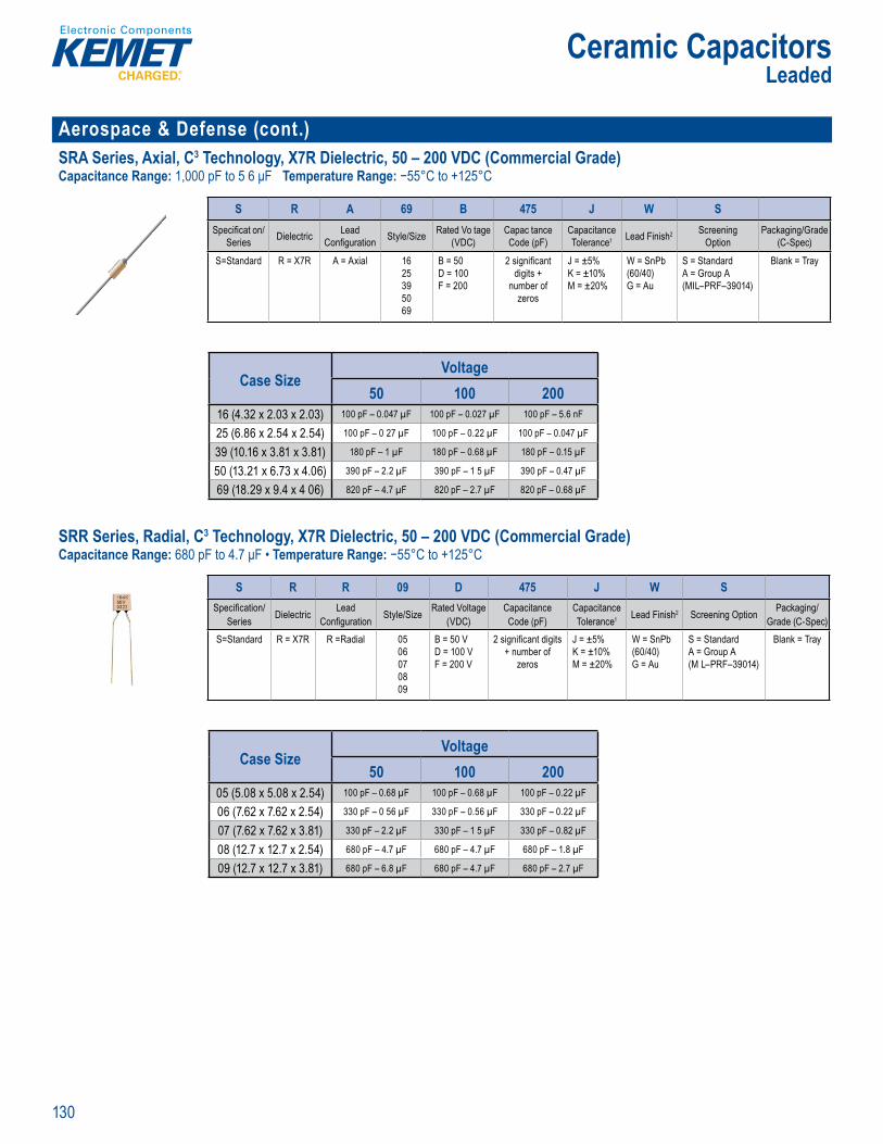
130
Ceramic CapacitorsLeaded
Aerospace & Defense (cont.)SRA Series, Axial, C3 Technology, X7R Dielectric, 50 – 200 VDC (Commercial Grade)Capacitance Range: 1,000 pF to 5 6 μF Temperature Range: −55°C to +125°C
• SnPb- oated lead fi
Ordering In ormation
S R A 69 B 475 J W SSpecifi cat on/
Series Dielectric Lead Confi guration Style/Size Rated Vo tage
(VDC)Capac tanceCode (pF)
CapacitanceTolerance1 Lead Finish2 Screening
OptionPackaging/Grade
(C-Spec)
S=Standard R = X7R A = Axial 1625395069
B = 50D = 100F = 200
2 signifi cant digits +
number of zeros
J = ±5%K = ±10%M = ±20%
W = SnPb (60/40)G = Au
S = StandardA = Group A(MIL–PRF–39014)
Blank = Tray
Case SizeVoltage
50 100 20016 (4.32 x 2.03 x 2.03) 100 pF – 0.047 µF 100 pF – 0.027 µF 100 pF – 5.6 nF
25 (6.86 x 2.54 x 2.54) 100 pF – 0 27 µF 100 pF – 0.22 µF 100 pF – 0.047 µF
39 (10.16 x 3.81 x 3.81) 180 pF – 1 µF 180 pF – 0.68 µF 180 pF – 0.15 µF
50 (13.21 x 6.73 x 4.06) 390 pF – 2.2 µF 390 pF – 1 5 µF 390 pF – 0.47 µF
69 (18.29 x 9.4 x 4 06) 820 pF – 4.7 µF 820 pF – 2.7 µF 820 pF – 0.68 µF
SRR Series, Radial, C3 Technology, X7R Dielectric, 50 – 200 VDC (Commercial Grade)Capacitance Range: 680 pF to 4.7 μF • Temperature Range: −55°C to +125°C
r etary and ro -5 C o 25 ope a tempera ure a D v lt g a ing f 5 1 d g Temp r u st b e d le No - la de ice min g nst l at n rns p q (
Technolo y and a e e r b r te p r t p tio ec no o f t res a ique l ad att ch nfi r t o ire int r l co necti n to Mu tila er Cer mic Ca ito LC )
p e m t o pa
haracterist c at e mpe s e mpa ed to ventio e technolog ls are
utl ned in U Pa ent be 493
s i
c it rs su t f
p e a cit p and bo s a minima c g itance w ference to amb e mperatu nge is ±15% fr -55°C +125°C
Order ng Informati n
S R R 09 D 475 J W SSpecifi cation/
Series Dielectric Lead Confi guration Style/Size Rated Voltage
(VDC)CapacitanceCode (pF)
CapacitanceTolerance1 Lead Finish2 Screening Option Packaging/
Grade (C-Spec)S=Standard R = X7R R =Radial 05
06070809
B = 50 VD = 100 VF = 200 V
2 signifi cant digits + number of
zeros
J = ±5%K = ±10%M = ±20%
W = SnPb (60/40)G = Au
S = StandardA = Group A (M L–PRF–39014)
Blank = Tray
Case SizeVoltage
50 100 20005 (5.08 x 5.08 x 2.54) 100 pF – 0.68 µF 100 pF – 0.68 µF 100 pF – 0.22 µF
06 (7.62 x 7.62 x 2.54) 330 pF – 0 56 µF 330 pF – 0.56 µF 330 pF – 0.22 µF
07 (7.62 x 7.62 x 3.81) 330 pF – 2.2 µF 330 pF – 1 5 µF 330 pF – 0.82 µF
08 (12.7 x 12.7 x 2.54) 680 pF – 4.7 µF 680 pF – 4.7 µF 680 pF – 1.8 µF
09 (12.7 x 12.7 x 3.81) 680 pF – 6.8 µF 680 pF – 4.7 µF 680 pF – 2.7 µF
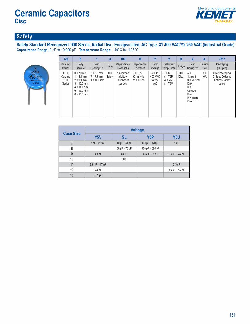
131
Ceramic CapacitorsDisc
Safety Safety Standard Recognized, 900 Series, Radial Disc, Encapsulated, AC Type, X1 400 VAC/Y2 250 VAC (Industrial Grade)Capacitance Range: 2 pF to 10,000 pF Temperature Range: −40°C to +125°C
p l p
(across-the- ine) ap lica
rdering nformation
C9 8 1 U 103 M Y V D A A 7317Ceramic Series
BodyDiameter
Lead Spacing1 2 4 Spec. Capacitance
Code (pF)Capacitance
ToleranceRated
VoltageDielectric/
Temp. Char. Design Lead Confi g.1 3 4
FailureRate
Packaging(C-Spec)
C9 = Ceramic
900 Series
0 = 7.0 mm1 = 8.0 mm2 = 9.0 mm3 = 10.0 mm4 = 11.0 mm6 = 13.0 mm8 = 15.0 mm
5 = 5.0 mm7 = 7.5 mm1 = 10.0 mm
U = Safety
2 signifi cantdigits +
number ofzeroes
J = ±5%K = ±10%M = ±20%
Y = X1 400 VAC /Y2 250
VAC
S = SL Y = Y5PW = Y5UV = Y5V
D = Disc
A = StraightB = Vertical KinkC = Outside KinkD = Inside Kink
A = N/A
See "Packaging C-Spec Ordering Options Table"
below
Case SizeVoltage
Y5V SL Y5P Y5U7 1 nF – 2.2 nF 10 pF – 51 pF 100 pF – 470 pF 1 nF
8 56 pF – 75 pF 560 pF – 680 pF
9 3 3 nF 82 pF 820 pF – 1 nF 1.5 nF – 2.2 nF
10 100 pF
11 3.9 nF – 4.7 nF 3 3 nF
13 6.8 nF 3.9 nF – 4.7 nF
15 0.01 µF

132
Ceramic CapacitorsDisc
Safety (cont.)Safety Standard Recognized, 900 Series, Radial Disc, Encapsulated, AC Type, X1 440 VAC/Y2 300 VAC (Industrial Grade)Capacitance Range: 2 pF to 10 000 pF • Temperature Range: −40 C to +125°C
r e ing f ma on
C9 7 1 U 472 M Z W D A A 7317Ceramic Series
BodyDiameter
Lead Spacing1 3 Spec. Capacitance
Code (pF)Capacitance
ToleranceRated
VoltageDielectric/
Temp. Char. Design Lead Confi g.2 3
FailureRate
Packaging(C-Spec)
C9 = Ceramic
900 Series
0 = 7.0 mm1 = 8.0 mm2 = 9 0 mm3 = 10.0 mm4 = 11.0 mm6 = 13.0 mm8 = 15 0 mm
7 = 7 5 mm1 = 10.0 mm
U = Safety
2 signifi cantdigits +
number ofzeroes
J = ±5%K = ±10%M = ±20%
Z = X1 440 VAC /Y2 300
VAC
S = SL Y = Y5PW = Y5UV = Y5V
D = Disc
A = StraightB = Vertical KinkC = Outside KinkD = Inside Kink
A = N/A
See "Packaging C-Spec O dering Options Table"
below
Case SizeVoltage
Y5V SL Y5P Y5U7 1 nF – 2.2 nF 10 pF – 51 pF 100 pF – 470 pF 1 nF
8 56 pF – 75 pF 560 pF – 680 pF
9 3 3 nF 82 pF 820 pF – 1 nF 1.5 nF – 2.2 nF
10 100 pF
11 3.9 nF – 4.7 nF 3 3 nF
13 6.8 nF 3.9 nF – 4.7 nF
15 0.01 µF Safety Standard Recognized, 900 Series, Radial Disc, Encapsulated, AS Type, X1 760 VAC/Y1 500 VAC (Industrial Grade)Capacitance Range: 2,200 pF • Temperature Range: −25°C to +125°C
vervi
MET 0 er es e apsu ated dial ded ceram sc capa s r sp fi ll esi ned f terferepp es li e fi lt i g i te i l
saf ty erti o s that req
s en
cit bu o ld r s o is
i i und ( pl c
th w ng vo of VA to lass X)and 0 AC e to nd ( ss Y) cati t ese afety acit t t st c EC St
nd ses up
t and
Safe y Standard Recog ized, 900 S ries, E capsulated, AS Typ X1 760 VAC/Y1 500 AC I
Ordering Information
C9 6 1 U 222 M W W D A A 7317Ceramic Series
BodyDiameter
Lead Spacing1 Spec. Capacitance
Code (pF)Capacitance
ToleranceRated
VoltageDielectric/
Temp. Char. Design Lead Confi g.1
FailureRate
Packaging(C-Spec)
C9 = Ceramic
900 Series
6 = 13.0 mm 1 = 10.0 mm U = Safety
2 signifi cantdigits +
number ofzeroes
M = ±20% W = X1 760 VAC /Y1 500
VAC
W = Y5U D = Disc
A = StraightB = Vertical KinkC = Outside Kink
A = N/A
See "Packaging C-Spec Ordering Options Table"
below
Case SizeVoltage
Y5U13 2 2 nF
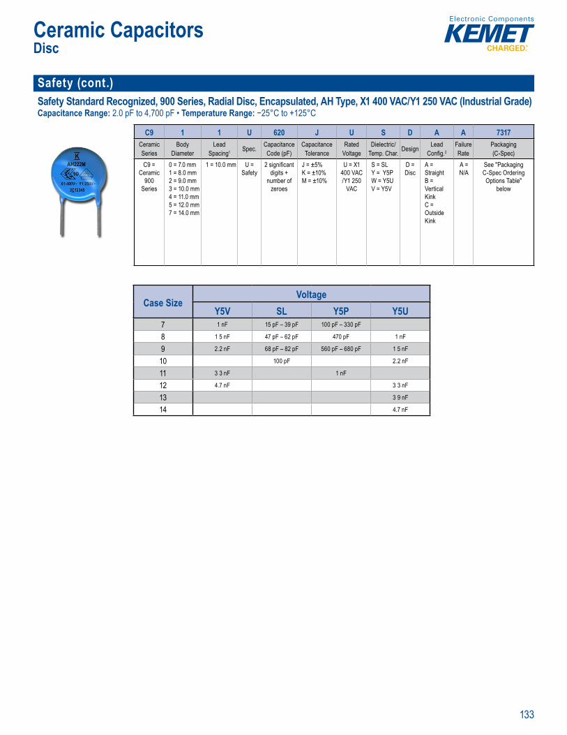
133
Ceramic CapacitorsDisc
Safety (cont.)Safety Standard Recognized, 900 Series, Radial Disc, Encapsulated, AH Type, X1 400 VAC/Y1 250 VAC (Industrial Grade)Capacitance Range: 2.0 pF to 4,700 pF • Temperature Range: −25°C to +125°C
primar y used in l ne-to- thi li t f il
rdering I ormatio
C9 1 1 U 620 J U S D A A 7317Ceramic Series
BodyDiameter
Lead Spacing1 Spec. Capacitance
Code (pF)Capacitance
ToleranceRated
VoltageDielectric/
Temp. Char. Design Lead Confi g.2
FailureRate
Packaging(C-Spec)
C9 = Ceramic
900 Series
0 = 7.0 mm1 = 8.0 mm2 = 9.0 mm3 = 10.0 mm4 = 11.0 mm5 = 12.0 mm7 = 14.0 mm
1 = 10.0 mm U = Safety
2 signifi cantdigits +
number ofzeroes
J = ±5%K = ±10%M = ±10%
U = X1 400 VAC /Y1 250
VAC
S = SL Y = Y5PW = Y5UV = Y5V
D = Disc
A = StraightB = Vertical KinkC = Outside Kink
A = N/A
See "Packaging C-Spec Ordering Options Table"
below
Case SizeVoltage
Y5V SL Y5P Y5U7 1 nF 15 pF – 39 pF 100 pF – 330 pF
8 1 5 nF 47 pF – 62 pF 470 pF 1 nF
9 2.2 nF 68 pF – 82 pF 560 pF – 680 pF 1 5 nF
10 100 pF 2.2 nF
11 3 3 nF 1 nF
12 4.7 nF 3 3 nF
13 3 9 nF
14 4.7 nF
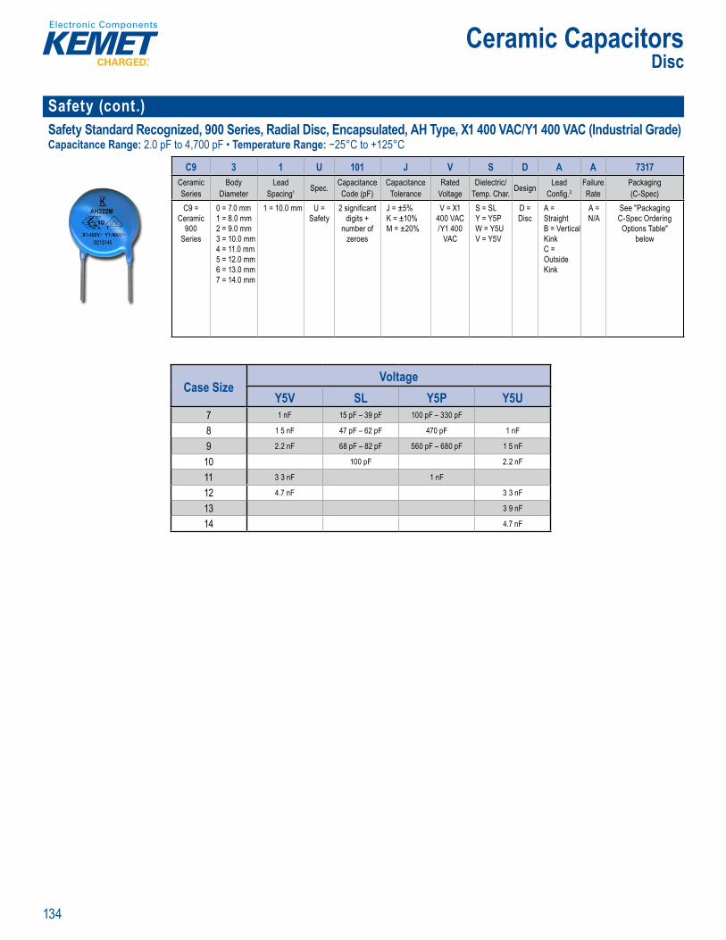
134
Ceramic CapacitorsDisc
Safety (cont.)Safety Standard Recognized, 900 Series, Radial Disc, Encapsulated, AH Type, X1 400 VAC/Y1 400 VAC (Industrial Grade)Capacitance Range: 2.0 pF to 4,700 pF • Temperature Range: −25°C to +125°C
d rin I o t
C9 3 1 U 101 J V S D A A 7317Ceramic Series
BodyDiameter
Lead Spacing1 Spec. Capacitance
Code (pF)Capacitance
ToleranceRated
VoltageDielectric/
Temp. Char. Design Lead Confi g.2
FailureRate
Packaging(C-Spec)
C9 = Ceramic
900 Series
0 = 7.0 mm1 = 8.0 mm2 = 9.0 mm3 = 10.0 mm4 = 11.0 mm5 = 12.0 mm6 = 13.0 mm7 = 14.0 mm
1 = 10.0 mm U = Safety
2 signifi cantdigits +
number ofzeroes
J = ±5%K = ±10%M = ±20%
V = X1 400 VAC /Y1 400
VAC
S = SL Y = Y5PW = Y5UV = Y5V
D = Disc
A = StraightB = Vertical KinkC = Outside Kink
A = N/A
See "Packaging C-Spec Ordering Options Table"
below
Case SizeVoltage
Y5V SL Y5P Y5U7 1 nF 15 pF – 39 pF 100 pF – 330 pF
8 1 5 nF 47 pF – 62 pF 470 pF 1 nF
9 2.2 nF 68 pF – 82 pF 560 pF – 680 pF 1 5 nF
10 100 pF 2.2 nF
11 3 3 nF 1 nF
12 4.7 nF 3 3 nF
13 3 9 nF
14 4.7 nF

135
Ceramic CapacitorsDisc
Safety (cont.)ERO610 Series, Radial AC Type, X1 440 VAC/Y2 250 VACCapacitance Range: 1,000 pF to 2,000 pF • Temperature Range: −40°C to +125°C
Ord ring Info mation
ERO610 R J 4250 K BF0Series Safety Class/Sub-Class Lead Spacing Capacitance Code (pF) Capacitance Tolerance Lead Confi guration
& PackagingERO610 R = X1/Y2 J = 5.0 mm
K = 7.5 mmDigits 2 – 4 indicate the fi rst three signifi cant fi gures of capacitance
in pF.The fi rst digit indicates the total number of signifi cant fi gures of
capacitance.Example: 12,000 pF = 5120
1,800 pF = 4180150 pF = 3150
K = ±10%M = ±20%
Please refer to datasheet
Case SizeVoltage
K40006.5 1 nF
8 1.5 nF – 1.8 nF
9 2.2 nF – 2.5 nF
10 3 3 nF
12 4.7 nF – 5 nF
17 6.8 nF – 8.2 nF
21 0.01 µF – 0.012 µF ERK610 Series, Radial AC Type, X1 440 VAC/Y2 300 VACCapacitance Range: 33 pF to 4,700 pF • Temperature Range: −40°C to +125°C
O ervie
O dering fo ma ion
ERK610 R K 4470 K CF0Series Safety Class/Sub-Class Lead Spacing Capacitance Code (pF) Capacitance Tolerance Lead Confi guration
& PackagingERK610 R = X1/Y2 K = 7.5 mm Digits 2 – 4 indicate the fi rst three
signifi cant fi gures of capacitance in pF.
The fi rst digit indicates the total number of signifi cant fi gures of
capacitance.Example: 12,000 pF = 5120
1,800 pF = 4180150 pF = 3150
K = ±10%M = ±20%
Please refer to datasheet
Case SizeVoltage
K1200 K1500 K2000 K4000 K6000 N7507 1 nF
8 68 pF 100 pF 150 pF – 330 pF 470 pF 1.5 nF 33 pF – 47 pF
9 680 pF
10 2.2 nF
11.5 3.3 nF
14 3 9 nF – 4.7 nF
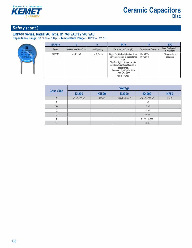
136
Ceramic CapacitorsDisc
Safety (cont.)ERP610 Series, Radial AC Type, X1 760 VAC/Y2 500 VACCapacitance Range: 33 pF to 4,700 pF • Temperature Range: −40°C to +125°C
O dering fo ma ion
ERP610 V H 4470 K EF0Series Safety Class/Sub-Class Lead Spacing Capacitance Code (pF) Capacitance Tolerance Lead Confi guration
& PackagingERP610 V = X1 / Y1 H = 12.5 mm Digits 2 – 4 indicate the fi rst three
signifi cant fi gures of capacitance in pF.
The fi rst digit indicates the total number of signifi cant fi gures of
capacitance.Example: 12,000 pF = 5120
1,800 pF = 4180150 pF = 3150
K = ±10%M = ±20%
Please refer to datasheet
Case SizeVoltage
K1200 K1500 K2000 K4000 N7508 47 pF – 68 pF 100 pF 150 pF – 330 pF 470 pF – 680 pF 33 pF
9 1 nF
10 1.5 nF
12 2.2 nF
13 2.7 nF
15 3.3 nF – 3.9 nF
17 4.7 nF
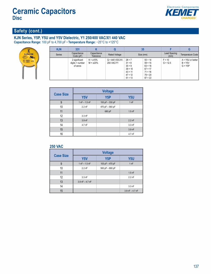
137
Ceramic CapacitorsDisc
Safety (cont.)KJN Series, Y5P, Y5U and Y5V Dielectric, Y1 250/400 VAC/X1 440 VACCapacitance Range: 100 pF to 4,700 pF • Temperature Range: −25°C to +125°C
Or ering Informa ion
KJN 331 K Q 35 F GSeries Capacitance
Code (pF)Capacitance
Tolerance Rated Voltage Size (mm) Lead Spacing(mm) Temperature Code
2 signifi cant digits + number
of zeros
K = ±10%M = ±20%
Q = 440 VDC/X1,250 VAC/Y1
28 = 7 31 = 8 35 = 9 39 = 10 43 = 11 47 = 1251 = 13
55 = 14 59 = 15 63 = 1667 = 1771 = 1879 = 2087 = 22
F = 10G = 12.5
A = Y5U or betterB = Y5VG = Y5P
Case SizeVoltage
Y5V Y5P Y5U9 1 nF – 1.5 nF 100 pF – 330 pF 1 nF
10 2.2 nF 470 pF – 560 pF
11 680 pF 1.5 nF
12 3.3 nF
13 3.9 nF 2.2 nF
14 4.7 nF 3.3 nF
15 3.9 nF
16 4.7 nF
250 VAC
Case SizeVoltage
Y5V Y5P Y5U9 1 nF – 1.5 nF 100 pF – 470 pF 1 nF
10 2.2 nF 560 pF – 680 pF
11 1.5 nF
12 3.3 nF 2.2 nF
13 3.9 nF – 4.7 nF
14 3.3 nF
15 3.9 nF – 4.7 nF
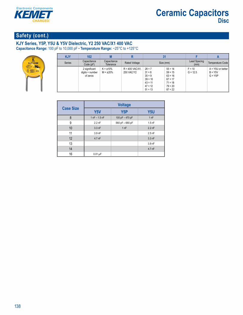
138
Ceramic CapacitorsDisc
Safety (cont.)KJY Series, Y5P, Y5U & Y5V Dielectric, Y2 250 VAC/X1 400 VACCapacitance Range: 100 pF to 10,000 pF • Temperature Range: −25°C to +125°C
Or ering Inf mati n
KJY 102 M R 31 F ASeries Capacitance
Code (pF)Capacitance
Tolerance Rated Voltage Size (mm) Lead Spacing(mm) Temperature Code
2 signifi cant digits + number
of zeros
K = ±10%M = ±20%
R = 400 VAC/X1,250 VAC/Y2
28 = 7 31 = 8 35 = 9 39 = 10 43 = 11 47 = 1251 = 13
55 = 14 59 = 15 63 = 1667 = 1771 = 1879 = 2087 = 22
F = 10G = 12.5
A = Y5U or betterB = Y5VG = Y5P
Case SizeVoltage
Y5V Y5P Y5U8 1 nF – 1.5 nF 100 pF – 470 pF 1 nF
9 2.2 nF 560 pF – 680 pF 1.5 nF
10 3.3 nF 1 nF 2.2 nF
11 3.9 nF 2.5 nF
12 4.7 nF 3.3 nF
13 3.9 nF
14 4.7 nF
16 0.01 µF

139
Ceramic CapacitorsDisc
Commercial Grade KHA Series, X7R Dielectric, 1,000 – 2,000 VDCCapacitance Range: 100 pF to 4,700 pF • Temperature Range: −55°C to +125°C
Or ering Informa ion
KHA 152 K N 35 C HSeries Capacitance
Code (pF)Capacitance
Tolerance Rated Voltage Size (mm) Lead Spacing(mm) Temperature Code
2 signifi cant digits + number
of zeros
K = ±10%M = ±20%
N = 1,000 VDCP = 2,000 VDC
28 = 7 31 = 8 35 = 9 39 = 10 43 = 11 47 = 1251 = 13
55 = 14 59 = 15 63 = 1667 = 1771 = 1879 = 2087 = 22
C = 5D = 7.5
H = X7R
1,000 VDC 2,000 VDC
Case SizeVoltage
X7R8.5 100 pF – 270 pF
9.5 330 pF – 560 pF
10.5 680 pF – 1 nF
12.5 1.2 nF – 1.5 nF
14.5 1.8 nF – 2.7 nF
16.5 3 3 nF
Case SizeVoltage
X7R5.5 100 pF – 470 pF
6.5 560 pF – 820 pF
7.5 1 nF – 1.2 nF
8.5 1.5 nF
9.5 1.8 nF
10.5 2 2 nF
12.5 2.7 nF – 3.3 nF
14.5 3.9 nF – 4.7 nF
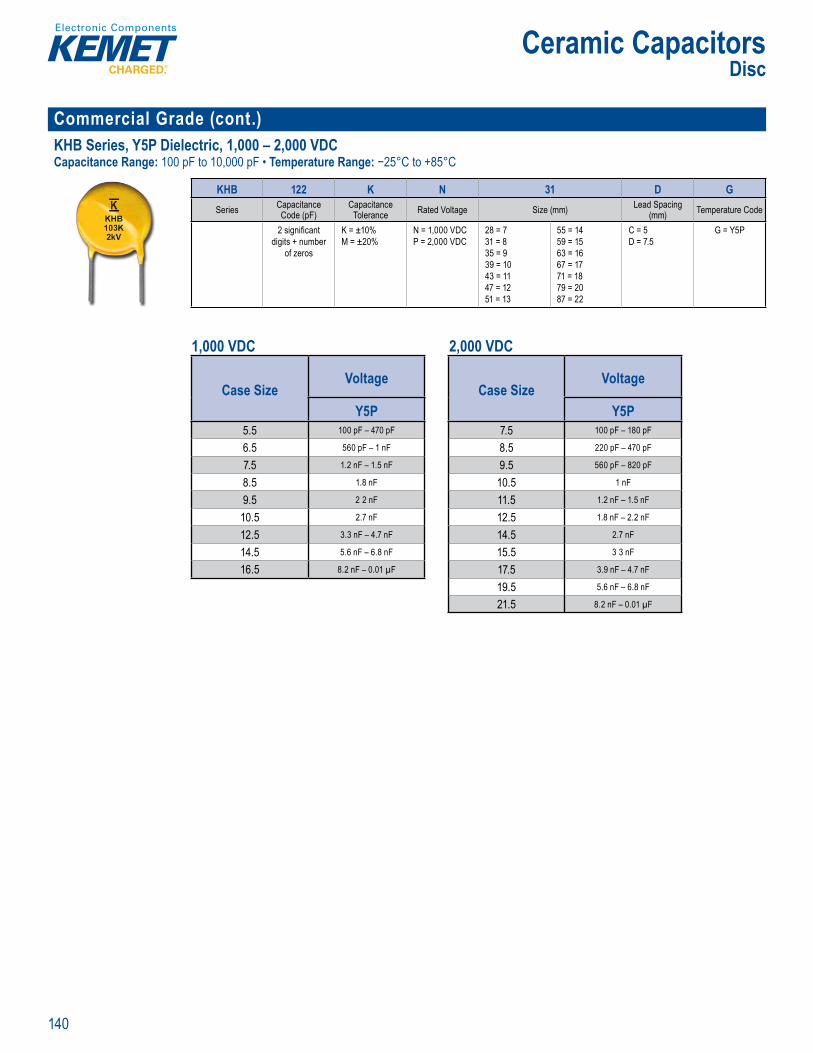
140
Ceramic CapacitorsDisc
Commercial Grade (cont.)KHB Series, Y5P Dielectric, 1,000 – 2,000 VDCCapacitance Range: 100 pF to 10,000 pF • Temperature Range: −25°C to +85°C
Or ering Inf mati n
KHB 122 K N 31 D GSeries Capacitance
Code (pF)Capacitance
Tolerance Rated Voltage Size (mm) Lead Spacing(mm) Temperature Code
2 signifi cant digits + number
of zeros
K = ±10%M = ±20%
N = 1,000 VDCP = 2,000 VDC
28 = 7 31 = 8 35 = 9 39 = 10 43 = 11 47 = 1251 = 13
55 = 14 59 = 15 63 = 1667 = 1771 = 1879 = 2087 = 22
C = 5D = 7.5
G = Y5P
1,000 VDC 2,000 VDC
Case SizeVoltage
Y5P7.5 100 pF – 180 pF
8.5 220 pF – 470 pF
9.5 560 pF – 820 pF
10.5 1 nF
11.5 1.2 nF – 1.5 nF
12.5 1.8 nF – 2.2 nF
14.5 2.7 nF
15.5 3 3 nF
17.5 3.9 nF – 4.7 nF
19.5 5.6 nF – 6.8 nF
21.5 8.2 nF – 0.01 µF
Case SizeVoltage
Y5P5.5 100 pF – 470 pF
6.5 560 pF – 1 nF
7.5 1.2 nF – 1.5 nF
8.5 1.8 nF
9.5 2 2 nF
10.5 2.7 nF
12.5 3.3 nF – 4.7 nF
14.5 5.6 nF – 6.8 nF
16.5 8.2 nF – 0.01 µF
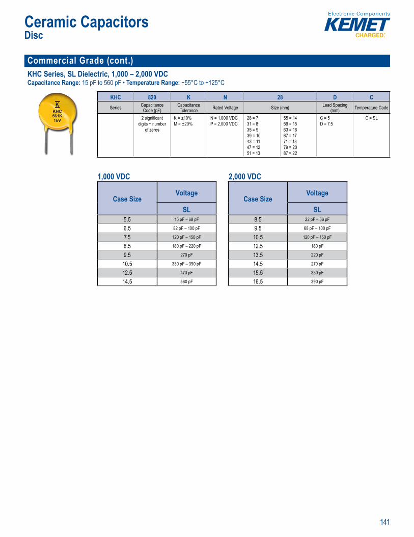
141
Ceramic CapacitorsDisc
Commercial Grade (cont.)KHC Series, SL Dielectric, 1,000 – 2,000 VDCCapacitance Range: 15 pF to 560 pF • Temperature Range: −55°C to +125°C
Ordering nformation
KHC 820 K N 28 D CSeries Capacitance
Code (pF)Capacitance
Tolerance Rated Voltage Size (mm) Lead Spacing(mm) Temperature Code
2 signifi cant digits + number
of zeros
K = ±10%M = ±20%
N = 1,000 VDCP = 2,000 VDC
28 = 7 31 = 8 35 = 9 39 = 10 43 = 11 47 = 1251 = 13
55 = 14 59 = 15 63 = 1667 = 1771 = 1879 = 2087 = 22
C = 5D = 7.5
C = SL
1,000 VDC 2,000 VDC
Case SizeVoltage
SL8.5 22 pF – 56 pF
9.5 68 pF – 100 pF
10.5 120 pF – 150 pF
12.5 180 pF
13.5 220 pF
14.5 270 pF
15.5 330 pF
16.5 390 pF
Case SizeVoltage
SL5.5 15 pF – 68 pF
6.5 82 pF – 100 pF
7.5 120 pF – 150 pF
8.5 180 pF – 220 pF
9.5 270 pF
10.5 330 pF – 390 pF
12.5 470 pF
14.5 560 pF

142
Film Capacitors
THROUGH-HOLE FILM CAPACITORS
General Purpose Pulse & AC Safety/EMI
Metallized Polyester
PME261 (P561)Impregnated Paper400 – 1,000 VDC
F461 – 464Halogen Free
160 – ,500 VDC
PHE450 (F450)DC Applications
250 – 3,000 VAC
R76DC & Pulse Applications
250 – 2,000 VDC
R73Radial
100 – 2,000 VDC
F871 – F873Halogen Free
Metallized Polypropylene330/480/760 VAC
R49Metallized Polypropylene
310 VAC/330 VAC
R47Metallized Polypropylene
440 VAC
P278Metallized Impregnated
Paper480 VAC
P410Metallized Impregnated
Paper300 VAC
PME271E (P277)Metallized Impregnated
Paper300 VAC
PHE844 (F844)Metallized Polypropylene
440/480 VAC
R4Metallized Polypropylene
440 VAC/5 0 VAC
P295Metallized Impregnated
Paper500 VA
F881Halogen Free
Meta lized Po propylene300 VAC
PHZ9004 (9004)Metal ized Polypropylene
300 VAC (3x X2)
PMZ2074 (P 74)Metallized Impregnated
Paper275 VAC (2x X2) PZB300 (P300)
Metallized ImpregnatedPaper
275 VAC (X2 2x Y2)
PME271Y (P271)Impregnated Paper
250 VAC
R41Meta lized Polyp pyle e
300 VAC
PME271Y A E (P272)Impregnated Paper
300 VAC
PME295 (P295)Metallized Impregnated
Paper440 VAC/480 VAC
R46Metallized Po ypropylene
310 V C
R46 (Miniature)Metallized Polypropylene
275 VAC
R46 – 125 CMetallized Polypropylene
275 VAC
PME264 (P264)Metallized Impregnated
Paper660 VAC
P409Metallized Impregnated
Paper275 VAC
PME271M (P276)Metallized Impregnated
Paper275 VAC
PFR (F411)Radial
63 – 1,000 VDC
A72Axial
100 – 2,000 VDC
R795 mm Lead Spacing
160 – 630 VDC
R75160 – 2,000 VDC
R74AC Applications250 – 900 VDC
R71SMPS PFC Applications
420 – 1,000 VDC
A70Axial
160 – 630 VDC
SMR (F211)Polyphenylene Sulfide
150 C50 – 400 VDC
F622 – 125 CHalogen Free
5 mm (Stacked)50 – 630 VDC
R6010 – 37.5 mm
50 – 1,000 VDC
R667.5 mm Lead Spacing
50 – 630 VDC
R825 mm Lead Spacing
50 – 400 VDC
RSB – 125 C5 mm (Stacked)50 – 630 VDC
Metallized Paper &Polyphenylene Sulfide
Single MetallizedPolypropylene
Double MetallizedPolypropylene
Film/FoilPolypropylene X1 Class X2 Class Y1 Class Y2 Cla s Multiple X & Y
A50Axial
50 – 1,000 VDC
MDK (F683/4/5/7/8)Dual In-LineHigh Current
50 – 630 VDC
F 62Metallized Polypropylene
310 VAC
R74 – 125 CAC Applications500 – 700 VDC
PHE845 (F845)Metallized Polypropylene
760 VAC
F611 & F6125 – 37.5 mm
50 – 1,000 VDC
F861Metallized Polypropylene
310 VAC
A Appli
RSMPS PFC Applicatio
20 – 1 00
A 0Ax al
160 630
m Lead
5 mm Lead Spacing50 – 40
SB – 5 mm (Stacked)50 – 630
AAxi l
50 0 VDC
(F6Dual In LineH gh Cu
Polyester(PET)
PolyethyleneNaphthalate
(PEN)
MetallizedPolyphenylene
Sulfide(PPS)
Y2 Class
SURFACE MOUNT FILM CAPACITORS
LDEUnencapsulated Stacked
50 – 1,000 VDC
LDBUnencapsulated Stacked
16 VDC & 50 VDC
SMP253 (P101)Metallized Impregnated
Paper250 VAC
SMC (F125)Encapsulated Stacked
50 – 400 VDC
SPC (F127)Encapsulated Double
Metallized100 – 630 VDC
GMC (F115)Encapsulated Stacked
Size 2220 – 656050 – 630 VDC
F161Encapsulated Stacked
50 – 400 VDC
MDC (F153/4/5/7/8)Dual In-LineHigh Current
50 – 630 VDCMDS (F173/4/5)
Dual In-LineHigh Current
50 – 630 VDC
GPC (F117)Encapsulated Double
Meta lized63 – 1,000 VDC
R 5AC App ications
00 – 70 D
M 1
400 – 1 000
160 – 2 500 V
P – ,
R76 250 – 2,000
ad a00 000
/480/
R49
VAC
R47
440
P278 a
480 P410
Pap300 VAC
ME 71E ap0 V C
HE844 ( yp
440/ 80 VA
R47
Pa
500 VAC
etal yp
3 0 VAC
PME271 (P271
R 1e l zed o yp
3 0 VA
PM 271Y A Impreg ated P
300 VAC
PME295 P2 5l i
VAC
PFR (F411)
– 1,
A7
– 2
R7
0 – 6
SMR ( 211)
15 40 D
F 2 – 125 C
5 mm Stac50 – 63 VDC
R60
Power Film Motor RunApplications
High VoltageTransient
Suppression
Low VoltageTransient
Suppression
CapacitiveAC Power Supply
Axial Radial Screw/FastonTerminal
Screw/FastonTerminal Radial Radial Radial
POWER & APPLICATION OPTIMIZED FILM CAPACITORS
C4DCGTO Snubbing
850 – 1,400 VDC/500 – 700 VAC
C4AS2 or 4 Leads
850 – 3,000 VDC/500 – 750 VAC
C4DELow Inductance
DC Link400 – 1,000 VDC
PMR205 (P405)Integrated Resistor
Metallized Impregnated Paper125 VAC/250 VDC
F5A Integrated
Varistor18 – 63 VDC
R47 X1 – X2Metallized Polypropylene
440 VAC
F862Metallized Polypropylene
310 VAC
R75 2/LMetallized Polypropylene
230 VAC / 250 VAC
PME271E (P277)Metal ized Impregnated
Paper300 VAC
PME271M X2 (P276)Metal ized Impregnated
Paper275 VAC
F5BIntegrated Suppression
Diode18– 63 VDC
F5DIntegrated
Ceramic Capacitor63 – 100 VDC
P409Integrated Resistor
Metallized Impregnated Paper275 VAC
P410Integrated 100 Ω ResistorMetallized Impregnated Paper
300 VACPMZ2035 (P435)
Integrated 100 Ω ResistorMetallized Impregnated Paper
300 VDC
F43Integrated Resistor
Metallized Polypropylene250 – 630 VDC
C27Plastic Case
425 – 450 VAC
C87Aluminum Case
470 VAC
C93Filter Applications400 – 600 VDC
C44AGeneral Purpose & Snubbing
400 – 1,500 VDC/250 – 630 VAC
C44BGeneral Purpose & Snubbing
1,200 – 2,400 VDC/500 – 1,000 VAC
C44P/C20APFC & AC Filter
330 – 1,000 VAC/700 – 2,300 VDC
C44UDC Link
700 – 1,300 VDC
C4AE2 or 4 Leads
DC Link450 – 1,100 VDC
C4BSIGBT Direct Mount850 – 3,000 VDC/
550 – 750 VAC
C4AT2 or 4 Leads
250 – 850 VDC/160 – 450 VAC
C4BTIGBT Direct Mount
400 – 850 VDC/250 – 450 VAC
C4CAxial Round
850 – 3,000 VDC/450 – 750 VAC
C4DR GTO Clamping
400 – 3,000 VDC/160 – 1,500 VAC
C4GAxial Round
250 – 850 VDC/160 – 450 VAC
C44HPFC & AC Filter330 – 440 VAC/
700 – 1,000 VDC
C9TPFC & AC Filter415 – 690 VAC
F862et l i d oly r
310 VA
PHE845
760
50 – 1,000 Ved 310
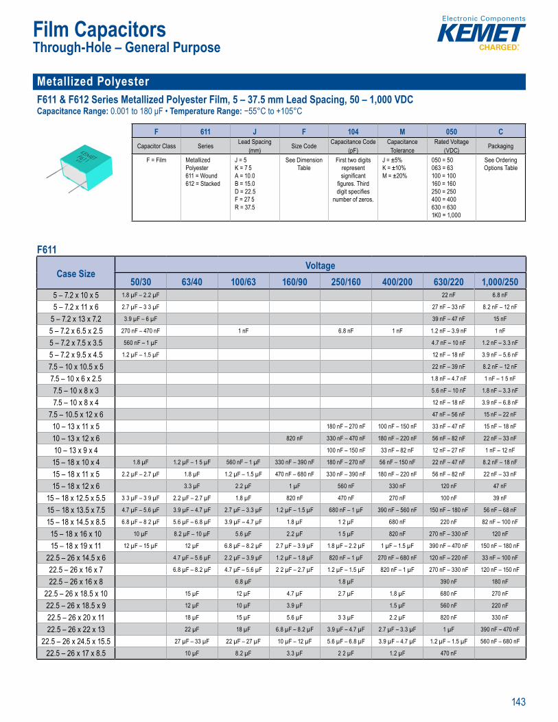
143
Film Capacitors
Metallized Polyester F611 & F612 Series Metallized Polyester Film, 5 – 37.5 mm Lead Spacing, 50 – 1,000 VDCCapacitance Range: 0.001 to 180 μF • Temperature Range: −55°C to +105°C
p RoHS Co
P rt Number System
F 611 J F 104 M 050 CCapacitor Class Series Lead Spacing
(mm) Size Code Capacitance Code (pF)
CapacitanceTolerance
Rated Voltage (VDC) Packaging
F = Film Metallized Polyester611 = Wound612 = Stacked
J = 5K = 7 5A = 10.0B = 15.0D = 22.5F = 27 5R = 37.5
See Dimension Table
First two digits represent signifi cant
fi gures. Third digit specifi es
number of zeros.
J = ±5% K = ±10% M = ±20%
050 = 50063 = 63100 = 100160 = 160250 = 250400 = 400630 = 6301K0 = 1,000
See OrderingOptions Table
F611
Case SizeVoltage
50/30 63/40 100/63 160/90 250/160 400/200 630/220 1,000/2505 – 7.2 x 10 x 5 1.8 µF – 2.2 µF 22 nF 6.8 nF
5 – 7.2 x 11 x 6 2.7 µF – 3 3 µF 27 nF – 33 nF 8.2 nF – 12 nF
5 – 7.2 x 13 x 7.2 3.9 µF – 6 µF 39 nF – 47 nF 15 nF
5 – 7.2 x 6.5 x 2.5 270 nF – 470 nF 1 nF 6.8 nF 1 nF 1.2 nF – 3.9 nF 1 nF
5 – 7.2 x 7.5 x 3.5 560 nF – 1 µF 4.7 nF – 10 nF 1.2 nF – 3.3 nF
5 – 7.2 x 9.5 x 4.5 1.2 µF – 1.5 µF 12 nF – 18 nF 3.9 nF – 5.6 nF
7.5 – 10 x 10.5 x 5 22 nF – 39 nF 8.2 nF – 12 nF
7.5 – 10 x 6 x 2.5 1.8 nF – 4.7 nF 1 nF – 1 5 nF
7.5 – 10 x 8 x 3 5.6 nF – 10 nF 1.8 nF – 3.3 nF
7.5 – 10 x 8 x 4 12 nF – 18 nF 3.9 nF – 6.8 nF
7.5 – 10.5 x 12 x 6 47 nF – 56 nF 15 nF – 22 nF
10 – 13 x 11 x 5 180 nF – 270 nF 100 nF – 150 nF 33 nF – 47 nF 15 nF – 18 nF
10 – 13 x 12 x 6 820 nF 330 nF – 470 nF 180 nF – 220 nF 56 nF – 82 nF 22 nF – 33 nF
10 – 13 x 9 x 4 100 nF – 150 nF 33 nF – 82 nF 12 nF – 27 nF 1 nF – 12 nF
15 – 18 x 10 x 4 1.8 µF 1.2 µF – 1 5 µF 560 nF – 1 µF 330 nF – 390 nF 180 nF – 270 nF 56 nF – 150 nF 22 nF – 47 nF 8.2 nF – 18 nF
15 – 18 x 11 x 5 2.2 µF – 2.7 µF 1.8 µF 1.2 µF – 1.5 µF 470 nF – 680 nF 330 nF – 390 nF 180 nF – 220 nF 56 nF – 82 nF 22 nF – 33 nF
15 – 18 x 12 x 6 3.3 µF 2.2 µF 1 µF 560 nF 330 nF 120 nF 47 nF
15 – 18 x 12.5 x 5.5 3 3 µF – 3 9 µF 2.2 µF – 2.7 µF 1.8 µF 820 nF 470 nF 270 nF 100 nF 39 nF
15 – 18 x 13.5 x 7.5 4.7 µF – 5.6 µF 3.9 µF – 4.7 µF 2.7 µF – 3.3 µF 1.2 µF – 1.5 µF 680 nF – 1 µF 390 nF – 560 nF 150 nF – 180 nF 56 nF – 68 nF
15 – 18 x 14.5 x 8.5 6.8 µF – 8 2 µF 5.6 µF – 6.8 µF 3.9 µF – 4.7 µF 1.8 µF 1 2 µF 680 nF 220 nF 82 nF – 100 nF
15 – 18 x 16 x 10 10 µF 8.2 µF – 10 µF 5.6 µF 2.2 µF 1 5 µF 820 nF 270 nF – 330 nF 120 nF
15 – 18 x 19 x 11 12 µF – 15 µF 12 µF 6.8 µF – 8.2 µF 2.7 µF – 3.9 µF 1.8 µF – 2.2 µF 1 µF – 1.5 µF 390 nF – 470 nF 150 nF – 180 nF
22.5 – 26 x 14.5 x 6 4.7 µF – 5.6 µF 2.2 µF – 3.9 µF 1.2 µF – 1.8 µF 820 nF – 1 µF 270 nF – 680 nF 120 nF – 220 nF 33 nF – 100 nF
22.5 – 26 x 16 x 7 6.8 µF – 8.2 µF 4.7 µF – 5.6 µF 2 2 µF – 2.7 µF 1.2 µF – 1.5 µF 820 nF – 1 µF 270 nF – 330 nF 120 nF – 150 nF
22.5 – 26 x 16 x 8 6.8 µF 1.8 µF 390 nF 180 nF
22.5 – 26 x 18.5 x 10 15 µF 12 µF 4.7 µF 2.7 µF 1.8 µF 680 nF 270 nF
22.5 – 26 x 18.5 x 9 12 µF 10 µF 3.9 µF 1.5 µF 560 nF 220 nF
22.5 – 26 x 20 x 11 18 µF 15 µF 5.6 µF 3 3 µF 2.2 µF 820 nF 330 nF
22.5 – 26 x 22 x 13 22 µF 18 µF 6.8 µF – 8.2 µF 3.9 µF – 4.7 µF 2.7 µF – 3.3 µF 1 µF 390 nF – 470 nF
22.5 – 26 x 24.5 x 15.5 27 µF – 33 µF 22 µF – 27 µF 10 µF – 12 µF 5.6 µF – 6.8 µF 3.9 µF – 4.7 µF 1.2 µF – 1.5 µF 560 nF – 680 nF
22.5 – 26 x 17 x 8.5 10 µF 8.2 µF 3.3 µF 2 2 µF 1.2 µF 470 nF
Through-Hole – General Purpose

144
Film Capacitors
Metallized Polyester (cont.) F611 & F612 Series Metallized Polyester Film, 5 – 37.5 mm Lead Spacing, 50 – 1,000 VDC (cont.)Capacitance Range: 0.001 to 180 μF Temperature Range: −55°C to +105°C
P t Number System
F 611 J F 104 M 050 CCapacitor Class Series Lead Spacing
(mm) Size Code Capacitance Code (pF)
CapacitanceTolerance
Rated Voltage (VDC) Packaging
F = Film Metallized Polyester611 = Wound612 = Stacked
J = 5K = 7 5A = 10.0B = 15.0D = 22.5F = 27 5R = 37.5
See Dimension Table
First two digits represent signifi cant
fi gures. Third digit specifi es
number of zeros.
J = ±5% K = ±10% M = ±20%
050 = 50063 = 63100 = 100160 = 160250 = 250400 = 400630 = 6301K0 = 1,000
See OrderingOptions Table
F611 (cont.)
Case SizeVoltage
63/40 100/63 160/90 250/160 400/200 630/220 1,000/25027.5 – 31.5 x 17 x 9 15 µF 10 µF 5.6 µF – 8.2 µF 2.2 µF – 4.7 µF 820 nF – 1.8 µF 330 nF – 680 nF 150 nF – 330 nF
27.5 – 31.5 x 20 x 11 18 µF – 22 µF 15 µF – 18 µF 10 µF – 12 µF 5.6 µF – 6.8 µF 2.2 µF – 2.7 µF 820 nF – 1 µF 390 nF – 470 nF
27.5 – 31.5 x 25 x 13 27 µF – 33 µF 22 µF – 27 µF 15 µF – 18 µF 8 2 µF – 12 µF 3.3 µF – 4.7 µF 1.2 µF – 1.8 µF 560 nF – 680 nF
27.5 – 31.5 x 28 x 14 39 µF 33 µF 22 µF 15 µF 5.6 µF 2.2 µF 820 nF
27.5 – 31.5 x 28 x 17.5 47 µF 39 µF 27 µF 18 µF 6.8 µF – 8.2 µF 2.2 µF – 2.7 µF 1 µF – 1 2 µF
27.5 – 31.5 x 29 x 19 56 µF 47 µF 33 µF 22 µF 1.5 µF
27.5 – 31.5 x 37 x 22 68 µF – 100 µF 56 µF – 82 µF 39 µF – 56 µF 27 µF – 33 µF 10 µF – 15 µF 3.3 µF – 4.7 µF 1.8 µF – 2.2 µF
37.5 – 41 x 22 x 11 22 µF – 27 µF 22 µF – 27 µF 15 µF – 18 µF 5.6 µF – 12 µF 2.2 µF – 4.7 µF 820 nF – 1.8 µF 470 nF – 680 nF
37.5 – 41 x 24 x 13 33 µF 33 µF 22 µF 15 µF 5.6 µF – 6.8 µF 2.2 µF 820 nF – 1 µF
37.5 – 41 x 26 x 15 39 µF – 47 µF 39 µF – 47 µF 27 µF – 33 µF 18 µF – 22 µF 8.2 µF 2.7 µF 1.2 µF
37.5 – 41 x 28.5 x 16 56 µF 56 µF 39 µF 27 µF 10 µF 3.3 µF 1.5 µF
37.5 – 41 x 32 x 19 68 µF 68 µF 47 µF 33 µF 12 µF 3.9 µF – 4.7 µF 1.8 µF – 2.2 µF
37.5 – 41 x 38 x 21 82 µF – 100 µF 82 µF – 100 µF 56 µF – 68 µF 39 µF – 47 µF 15 µF – 18 µF 5.6 µF – 6.8 µF 2.7 µF
37.5 – 41 x 44 x 24 120 µF – 150 µF 120 µF – 150 µF 82 µF – 100 µF 56 µF – 68 µF 22 µF – 27 µF 8.2 µF – 10 µF 3.3 µF – 3.9 µF
37.5 – 41 x 45 x 30 180 µF 180 µF 120 µF 82 µF 33 µF 12 µF 4.7 µF – 5.6 µF
Through-Hole – General Purpose

145
Film Capacitors
Metallized Polyester (cont.) F611 & F612 Series Metallized Polyester Film, 5 – 37.5 mm Lead Spacing, 50 – 1,000 VDC (cont.)Capacitance Range: 0.001 to 180 μF • Temperature Range: −55°C to +105°C
ape a RoHS Co
P rt Nu ber System
F 611 J F 104 M 050 CCapacitor Class Series Lead Spacing
(mm) Size Code Capacitance Code (pF)
CapacitanceTolerance
Rated Voltage (VDC) Packaging
F = Film Metallized Polyester611 = Wound612 = Stacked
J = 5K = 7 5A = 10.0B = 15.0D = 22.5F = 27 5R = 37.5
See Dimension Table
First two digits represent signifi cant
fi gures. Third digit specifi es
number of zeros.
J = ±5% K = ±10% M = ±20%
050 = 50063 = 63100 = 100160 = 160250 = 250400 = 400630 = 6301K0 = 1,000
See OrderingOptions Table
F612
Case SizeVoltage
50/30 63/40 100/63 160/90 250/140 250/160 400/160 400/2005 – 7.2 x 10 x 5 1 µF 560 nF – 680 nF 150 nF 82 nF – 100 nF 47 nF 27 nF – 33 nF
5 – 7.2 x 11 x 6 1.2 µF – 1.5 µF 820 nF – 1 µF 180 nF – 220 nF 120 nF – 150 nF 68 nF 39 nF – 56 nF
5 – 7.2 x 6.5 x 2.5 100 nF – 220 nF 1.2 nF – 120 nF 22 nF – 27 nF 8.2 nF – 18 nF 6.8 nF – 8.2 nF 1 2 nF – 4.7 nF
5 – 7.2 x 7.5 x 3.5 270 nF – 470 nF 150 nF – 270 nF 47 nF – 68 nF 22 nF – 39 nF 15 nF – 18 nF 5.6 nF – 82 nF
5 – 7.2 x 9.5 x 4.5 560 nF – 820 nF 330 nF – 470 nF 82 nF – 120 nF 47 nF – 68 nF 33 nF – 39 nF 15 nF – 22 nF
7.5 – 10 x 10.5 x 5 1.8 µF – 3.3 µF 1.2 µF – 1.5 µF 820 nF – 1 µF 180 nF – 220 nF 68 nF – 82 nF
7.5 – 10 x 8 x 3 680 nF – 1 µF 330 nF – 470 nF 68 nF – 220 nF 22 nF – 68 nF 6.8 nF – 27 nF
7.5 – 10 x 9 x 4 1.2 µF – 1.5 µF 560 nF – 1 µF 270 nF – 680 nF 82 nF – 150 nF 33 nF – 56 nF
7.5 – 10.5 x 12 x 6 3.9 µF – 4.7 µF 1.8 µF – 3.3 µF 1.5 µF – 1.8 µF 270 nF – 390 nF 100 nF – 150 nF
10 – 13 x 11 x 5 2.7 µF – 3.9 µF 1.5 µF – 2.7 µF 1 µF – 1.5 µF 390 nF – 560 nF
10 – 13 x 12 x 6 4.7 µF – 5.6 µF 3.3 µF – 3.9 µF 1.8 µF 680 nF
10 – 13 x 9 x 4 1.2 µF – 2.2 µF 1 µF – 1.2 µF 330 nF – 820 nF 180 nF – 330 nF
Through-Hole – General Purpose
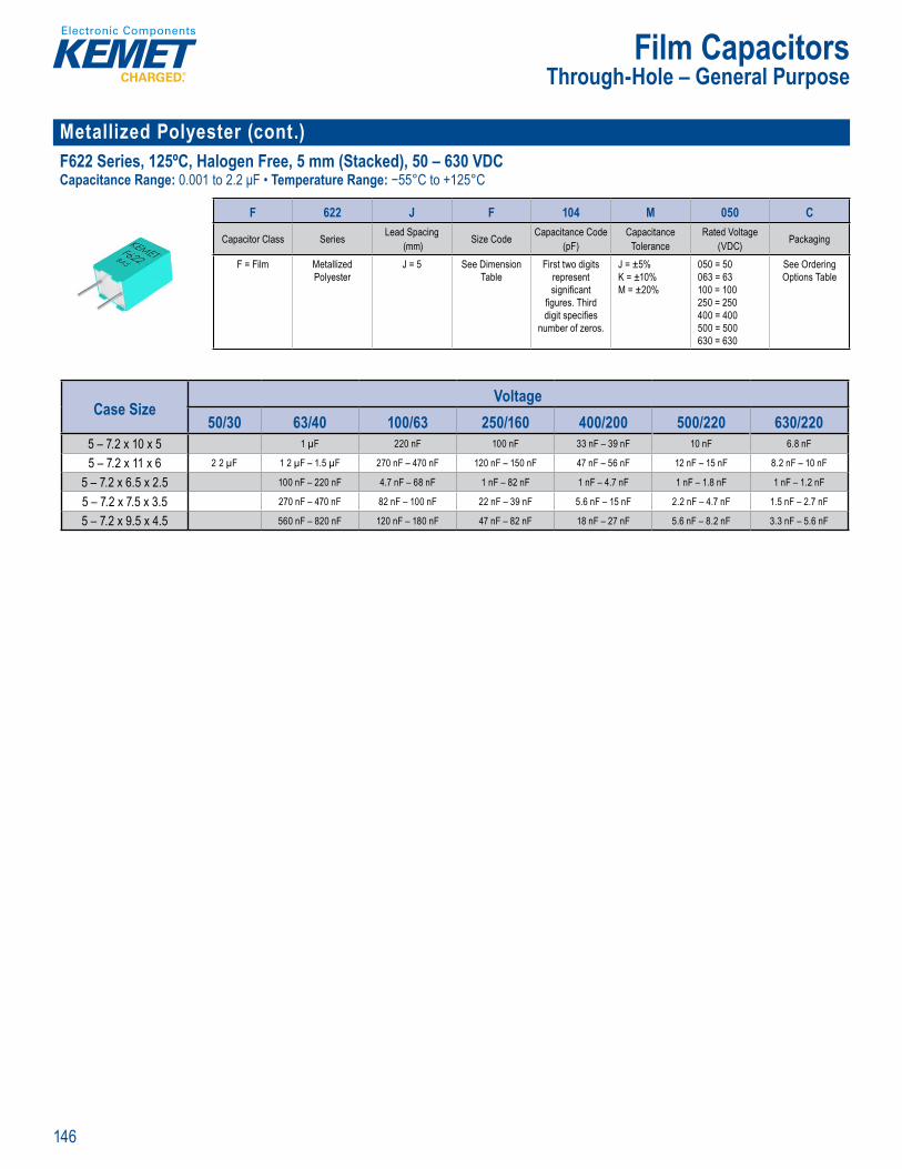
146
Film Capacitors
Metallized Polyester (cont.)F622 Series, 125ºC, Halogen Free, 5 mm (Stacked), 50 – 630 VDCCapacitance Range: 0.001 to 2.2 μF • Temperature Range: −55°C to +125°C
P rt u ber S stem
F 622 J F 104 M 050 C
Capacitor Class Series Lead Spacing (mm) Size Code Capacitance Code
(pF)Capacitance
ToleranceRated Voltage
(VDC) Packaging
F = Film Metallized Polyester
J = 5 See Dimension Table
First two digits represent signifi cant
fi gures. Third digit specifi es
number of zeros.
J = ±5% K = ±10% M = ±20%
050 = 50063 = 63100 = 100250 = 250400 = 400500 = 500630 = 630
See Ordering Options Table
Case SizeVoltage
50/30 63/40 100/63 250/160 400/200 500/220 630/2205 – 7.2 x 10 x 5 1 µF 220 nF 100 nF 33 nF – 39 nF 10 nF 6.8 nF
5 – 7.2 x 11 x 6 2 2 µF 1 2 µF – 1.5 µF 270 nF – 470 nF 120 nF – 150 nF 47 nF – 56 nF 12 nF – 15 nF 8.2 nF – 10 nF
5 – 7.2 x 6.5 x 2.5 100 nF – 220 nF 4.7 nF – 68 nF 1 nF – 82 nF 1 nF – 4.7 nF 1 nF – 1.8 nF 1 nF – 1.2 nF
5 – 7.2 x 7.5 x 3.5 270 nF – 470 nF 82 nF – 100 nF 22 nF – 39 nF 5.6 nF – 15 nF 2.2 nF – 4.7 nF 1.5 nF – 2.7 nF
5 – 7.2 x 9.5 x 4.5 560 nF – 820 nF 120 nF – 180 nF 47 nF – 82 nF 18 nF – 27 nF 5.6 nF – 8.2 nF 3.3 nF – 5.6 nF
Through-Hole – General Purpose
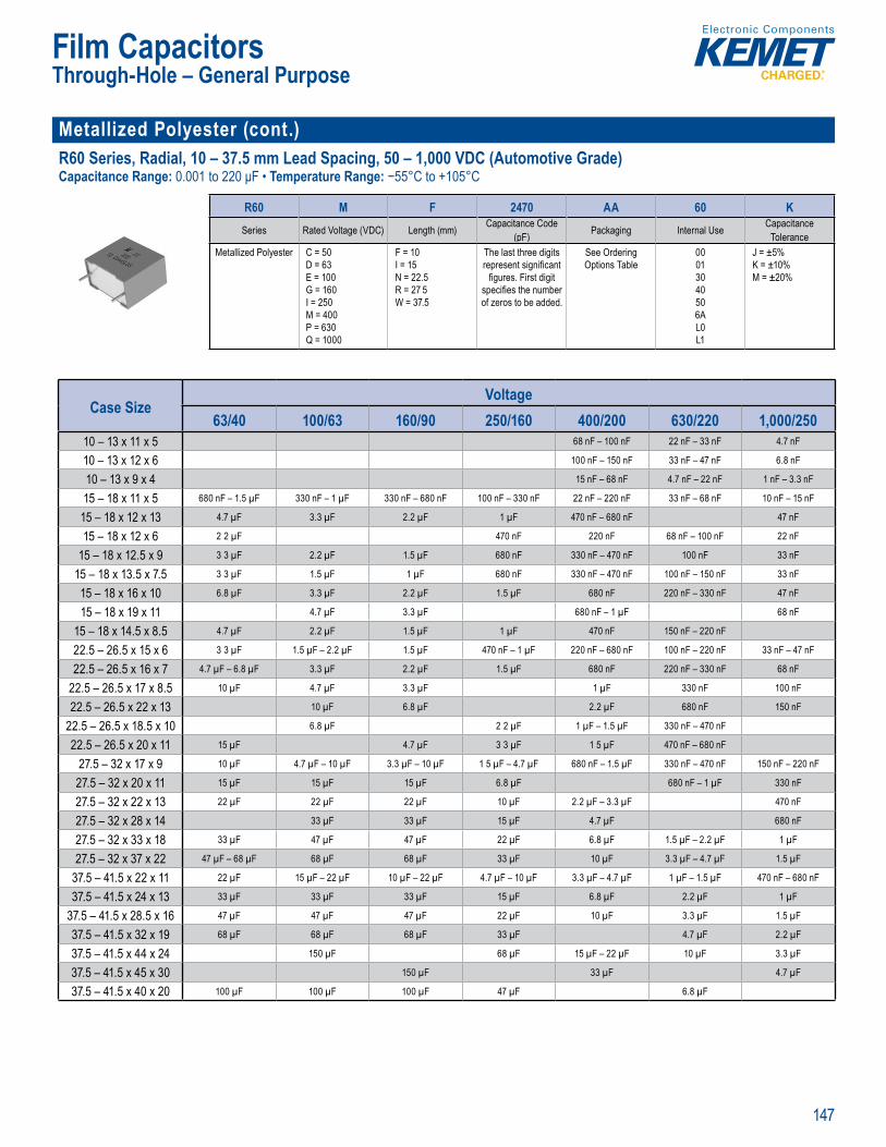
147
Film Capacitors
Metallized Polyester (cont.)R60 Series, Radial, 10 – 37.5 mm Lead Spacing, 50 – 1,000 VDC (Automotive Grade)Capacitance Range: 0.001 to 220 μF • Temperature Range: −55°C to +105°C
RoHS com
P rt Nu ber Sys em
R60 M F 2470 AA 60 KSeries Rated Voltage (VDC) Length (mm) Capacitance Code
(pF) Packaging Internal Use CapacitanceTolerance
Metallized Polyester C = 50D = 63E = 100G = 160I = 250M = 400P = 630Q = 1000
F = 10I = 15N = 22.5R = 27 5W = 37.5
The last three digits represent signifi cant
fi gures. First digit specifi es the number of zeros to be added.
See Ordering Options Table
00013040506AL0L1
J = ±5% K = ±10%M = ±20%
Case SizeVoltage
63/40 100/63 160/90 250/160 400/200 630/220 1,000/25010 – 13 x 11 x 5 68 nF – 100 nF 22 nF – 33 nF 4.7 nF
10 – 13 x 12 x 6 100 nF – 150 nF 33 nF – 47 nF 6.8 nF
10 – 13 x 9 x 4 15 nF – 68 nF 4.7 nF – 22 nF 1 nF – 3.3 nF
15 – 18 x 11 x 5 680 nF – 1.5 µF 330 nF – 1 µF 330 nF – 680 nF 100 nF – 330 nF 22 nF – 220 nF 33 nF – 68 nF 10 nF – 15 nF
15 – 18 x 12 x 13 4.7 µF 3.3 µF 2.2 µF 1 µF 470 nF – 680 nF 47 nF
15 – 18 x 12 x 6 2 2 µF 470 nF 220 nF 68 nF – 100 nF 22 nF
15 – 18 x 12.5 x 9 3 3 µF 2.2 µF 1.5 µF 680 nF 330 nF – 470 nF 100 nF 33 nF
15 – 18 x 13.5 x 7.5 3 3 µF 1.5 µF 1 µF 680 nF 330 nF – 470 nF 100 nF – 150 nF 33 nF
15 – 18 x 16 x 10 6.8 µF 3.3 µF 2.2 µF 1.5 µF 680 nF 220 nF – 330 nF 47 nF
15 – 18 x 19 x 11 4.7 µF 3.3 µF 680 nF – 1 µF 68 nF
15 – 18 x 14.5 x 8.5 4.7 µF 2.2 µF 1.5 µF 1 µF 470 nF 150 nF – 220 nF
22.5 – 26.5 x 15 x 6 3 3 µF 1.5 µF – 2.2 µF 1.5 µF 470 nF – 1 µF 220 nF – 680 nF 100 nF – 220 nF 33 nF – 47 nF
22.5 – 26.5 x 16 x 7 4.7 µF – 6.8 µF 3.3 µF 2.2 µF 1.5 µF 680 nF 220 nF – 330 nF 68 nF
22.5 – 26.5 x 17 x 8.5 10 µF 4.7 µF 3.3 µF 1 µF 330 nF 100 nF
22.5 – 26.5 x 22 x 13 10 µF 6.8 µF 2.2 µF 680 nF 150 nF
22.5 – 26.5 x 18.5 x 10 6.8 µF 2 2 µF 1 µF – 1.5 µF 330 nF – 470 nF
22.5 – 26.5 x 20 x 11 15 µF 4.7 µF 3 3 µF 1 5 µF 470 nF – 680 nF
27.5 – 32 x 17 x 9 10 µF 4.7 µF – 10 µF 3.3 µF – 10 µF 1 5 µF – 4.7 µF 680 nF – 1.5 µF 330 nF – 470 nF 150 nF – 220 nF
27.5 – 32 x 20 x 11 15 µF 15 µF 15 µF 6.8 µF 680 nF – 1 µF 330 nF
27.5 – 32 x 22 x 13 22 µF 22 µF 22 µF 10 µF 2.2 µF – 3.3 µF 470 nF
27.5 – 32 x 28 x 14 33 µF 33 µF 15 µF 4.7 µF 680 nF
27.5 – 32 x 33 x 18 33 µF 47 µF 47 µF 22 µF 6.8 µF 1.5 µF – 2.2 µF 1 µF
27.5 – 32 x 37 x 22 47 µF – 68 µF 68 µF 68 µF 33 µF 10 µF 3.3 µF – 4.7 µF 1.5 µF
37.5 – 41.5 x 22 x 11 22 µF 15 µF – 22 µF 10 µF – 22 µF 4.7 µF – 10 µF 3.3 µF – 4.7 µF 1 µF – 1.5 µF 470 nF – 680 nF
37.5 – 41.5 x 24 x 13 33 µF 33 µF 33 µF 15 µF 6.8 µF 2.2 µF 1 µF
37.5 – 41.5 x 28.5 x 16 47 µF 47 µF 47 µF 22 µF 10 µF 3.3 µF 1.5 µF
37.5 – 41.5 x 32 x 19 68 µF 68 µF 68 µF 33 µF 4.7 µF 2.2 µF
37.5 – 41.5 x 44 x 24 150 µF 68 µF 15 µF – 22 µF 10 µF 3.3 µF
37.5 – 41.5 x 45 x 30 150 µF 33 µF 4.7 µF
37.5 – 41.5 x 40 x 20 100 µF 100 µF 100 µF 47 µF 6.8 µF
Through-Hole – General Purpose

148
Film Capacitors
Metallized Polyester (cont.)R60 Series, Radial, 10 – 37.5 mm Lead Spacing, 63 – 1,000 VDC (Automotive Grade) (cont.)Capacitance Range: 0.001 to 220 μF • Temperature Range: −55°C to +105°C
P rt Nu ber Sys em
R60 M F 2470 AA 60 KSeries Rated Voltage (VDC) Length (mm) Capacitance Code
(pF) Packaging Internal Use CapacitanceTolerance
Metallized Polyester C = 50D = 63E = 100G = 160I = 250M = 400P = 630Q = 1000
F = 10I = 15N = 22.5R = 27 5W = 37.5
The last three digits represent signifi cant
fi gures. First digit specifi es the number of zeros to be added.
See Ordering Options Table
00013040506AL0L1
J = ±5% K = ±10%M = ±20%
Stacked
Case SizeVoltage
50/30 63/40 100/63 160/90 250/160 400/200 630/22010 – 13 x 11 x 5 3.3 µF 1.5 µF – 2.2 µF 1 µF – 1 5 µF 470 nF 220 nF – 330 nF 100 nF 33 nF – 47 nF
10 – 13 x 9 x 4 1.5 µF – 2.2 µF 1 µF 330 nF – 680 nF 220 nF – 330 nF 100 nF – 150 nF 33 nF – 68 nF 10 nF – 22 nF
10 – 13 x 12 x 6 4.7 µF – 5.6 µF 3.3 µF 680 nF 470 nF 150 nF
R66 Series, Radial, 7.5 mm Lead Spacing, 50 – 630 VDC (Automotive Grade)Capacitance Range: 0.001 to 4.7 μF • Temperature Range: −55°C to +105°C
– 30 0 001
• R nce an rmination• e pac ag g dance th 2 el
Rad a ea s are e s
wi h thermosett ng esin in a box of ater al m eting he UL 94V 0 equi ements.
tive e et t
Part u ber S stem
R66 E D 3100 AA 7A JSeries Rated Voltage (VDC) Length (mm) Capacitance Code
(pF) Packaging Internal Use CapacitanceTolerance
Metallized Polyester C = 50D = 63E = 100I = 250M = 400P = 630
D = 7.5 The last three digits represent signifi cant
fi gures. First digit specifi es the number of zeros to be added.
See Ordering Options Table
106A7A
J = ±5% K = ±10%M = ±20%
Case SizeVoltage630/220
7.5 – 10 x 8 x 3 1 nF – 4.7 nF
7.5 – 10 x 9 x 4 6.8 nF
Stacked
Case SizeVoltage
50/30 63/40 100/63 250/160 400/200 630/2207.5 – 10 x 10.5 x 5 2.2 µF 1.5 µF 1 µF 220 nF 68 nF 22 nF
7.5 – 10 x 8 x 3 680 nF – 1 µF 330 nF – 470 nF 68 nF – 220 nF 22 nF – 68 nF 6.8 nF – 22 nF
7.5 – 10 x 9 x 4 1.5 µF 680 nF – 1 µF 330 nF – 680 nF 100 nF – 150 nF 33 nF – 47 nF 10 nF – 15 nF
7.5 – 10.5 x 12 x 6 4.7 µF 2 2 µF – 3 3 µF 1.5 µF 330 nF 100 nF – 150 nF 33 nF – 47 nF
Through-Hole – General Purpose

149
Film Capacitors
Metallized Polyester (cont.)R82 Series, 5 mm Lead Spacing, 50 – 400 VDC (Automotive Grade)Capacitance Range: 0.001 to 4.7 μF • Temperatu e Range: −55°C to +105°C
RoHS com
Part Nu ber System
R82 D C 3470 AA 60 JSeries Rated Voltage (VDC) Length (mm) Capacitance Code
(pF) Packaging Internal Use CapacitanceTolerance
Metallized Polyester C = 50D 63E = 100I = 250M = 400
C = 5.0 The last three digits represent sign fi cant
fi gures. First digit specifi es the number of zeros to be added.
See Ordering Options Table
30506070
J = ±5% K = ±10%M = ±20%
Case SizeVoltage50/30
5 – 7.2 x 13 x 7.2 3.3 µF – 4.7 µF
Stacked
Case SizeVoltage
50/30 63/40 100/63 250/140 250/160 400/160 400/2005 – 7.2 x 10 x 5 1 µF 680 nF 150 nF 100 nF 47 nF 33 nF
5 – 7.2 x 11 x 6 2.2 µF 1.5 µF 1 µF 220 nF 150 nF 68 nF 47 nF
5 – 7.2 x 6.5 x 2.5 100 nF – 220 nF 1 nF – 100 nF 22 nF 6.8 nF – 15 nF 6.8 nF 1 nF – 4.7 nF
5 – 7.2 x 7.5 x 3.5 330 nF – 470 nF 150 nF – 220 nF 47 nF – 68 nF 22 nF – 33 nF 15 nF 6.8 nF – 10 nF
5 – 7.2 x 9.5 x 4.5 680 nF 330 nF – 470 nF 100 nF 47 nF – 68 nF 33 nF 15 nF – 22 nF
RSB Series, 125ºC, 5 mm (Stacked), 50 – 630 VDC (Automotive Grade)Capacitance Range: 0.001 to 2.2 μF • Temperature Range: −55°C to +125°C
lera c % sta d
• eratu to p i nt nd ea i io s eel a ag ng r nc w t I 6 2
d tech ) with radial eads ned re R
ads are e ectrica we de et la e wind d with
n ox 0
m
y p ling de or a signa o hig
freque pulse logic rc apacito electro ompac lam fo ito s aut DC m f he ine pp ic
(A omot v
Part u ber System
RSB D C 3100 AA 00 JSeries Rated Voltage (VDC) Length (mm) Capacitance Code
(pF) Packaging Internal Use CapacitanceTolerance
Metallized Polyester C = 50D = 63E = 100I = 250M = 400W = 500P = 630
C = 5.0 The last three digits represent signifi cant
fi gures. First digit specifi es the
number of zeros to be added.
See Ordering Options Table
30506070
J = ±5% K = ±10%M = ±20%
Case SizeVoltage
50/30 63/40 100/63 250/160 400/200 500/220 630/2205 – 7.2 x 10 x 5 1 µF 220 nF 100 nF 33 nF 10 nF 6.8 nF
5 – 7.2 x 11 x 6 2.2 µF 1.5 µF 330 nF – 470 nF 150 nF 47 nF 15 nF 10 nF
5 – 7.2 x 6.5 x 2.5 100 nF – 220 nF 4.7 nF – 68 nF 1 nF – 15 nF 1 nF – 4.7 nF 1 nF – 1 5 nF 1 nF
5 – 7.2 x 7.5 x 3.5 330 nF – 470 nF 100 nF 22 nF – 33 nF 6.8 nF – 15 nF 2.2 nF – 4.7 nF 1.5 nF – 2.2 nF
5 – 7.2 x 9.5 x 4.5 680 nF 150 nF 47 nF – 68 nF 22 nF 6.8 nF 3.3 nF – 4.7 nF
Through-Hole – General Purpose

150
Film Capacitors
Metallized Polyester (cont.)A50 Series Axial Pulse DC Transient, 50 – 1,000 VDC (Automotive Grade)Capacitance Range: 0.001 to 10 µF • Temperature Range: −55°C to +105°C
P rt Number Syst m
A50 C F 3470 AA 00 JSeries Rated Voltage (VDC) Length (mm) Capacitance Code
(pF) Packaging Internal Use CapacitanceTolerance
Metallized Polyester C = 50D = 63E = 100I = 250M = 400P = 630Q = 1000
F = 11H= 14K = 20.5Q = 28T = 33
The last three digits represent signifi cant
fi gures. First digit specifi es the
number of zeros to be added.
See Ordering Options Table
00, 60 (Standard) J = ±5% K = ±10% M = ±20%
Case SizeVoltage
50/30 63/40 100/63 250/160 400/200 630/220 1,000/2505 x 11 470 nF – 680 nF 330 nF 100 nF – 220 nF 47 nF – 68 nF 10 nF – 33 nF 1 nF – 6.8 nF
5 x 14 10 nF – 15 nF
5.5 x 14 100 nF – 150 nF
6 x 14 470 nF – 680 nF 330 nF – 470 nF 47 nF – 68 nF 22 nF
6 x 20.5 330 nF 150 nF 33 nF – 47 nF
6.5 x 11 1 µF
6.5 x 14 220 nF 100 nF 1 nF – 3.3 nF
6.5 x 20.5 1.5 µF
7 x 14 1.5 µF 1 µF 680 nF
7 x 20.5 1 µF 470 nF 68 nF 10 nF
7 x 28 100 nF
7.5 x 14 4.7 nF
7.5 x 20.5 3 3 µF 220 nF 15 nF
8 x 14 2 2 µF 6.8 nF
8 x 20.5 2 2 µF 1.5 µF
8 x 28 33 nF
8.5 x 20.5 4.7 µF 680 nF 330 nF
8.5 x 28 1 µF – 1.5 µF 470 nF 150 nF
9 x 20.5 22 nF
9 x 28 47 nF
9.5 x 20.5 3 3 µF 2 2 µF
9.5 x 28 4.7 µF 3 3 µF
10 x 20.5 6.8 µF
10 x 28 680 nF 220 nF
10 x 33 4.7 µF
10.5 x 28 68 nF
10.5 x 33 1 µF 330 nF
11 x 28 6.8 µF
11 x 33 2 2 µF
11.5 x 33 10 µF
Through-Hole – General Purpose
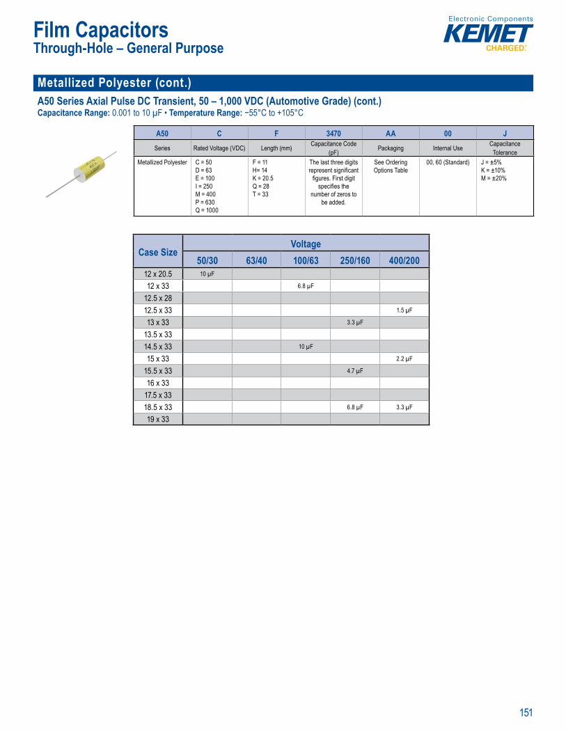
151
Film Capacitors
Metallized Polyester (cont.)A50 Series Axial Pulse DC Transient, 50 – 1,000 VDC (Automotive Grade) (cont.)Capacitance Range: 0.001 to 10 µF • Temperature Range: −55°C to +105°C
Opera ing
P rt Number Syst m
A50 C F 3470 AA 00 JSeries Rated Voltage (VDC) Length (mm) Capacitance Code
(pF) Packaging Internal Use CapacitanceTolerance
Metallized Polyester C = 50D = 63E = 100I = 250M = 400P = 630Q = 1000
F = 11H= 14K = 20.5Q = 28T = 33
The last three digits represent signifi cant
fi gures. First digit specifi es the
number of zeros to be added.
See Ordering Options Table
00, 60 (Standard) J = ±5% K = ±10% M = ±20%
Case SizeVoltage
50/30 63/40 100/63 250/160 400/20012 x 20.5 10 µF
12 x 33 6.8 µF
12.5 x 2812.5 x 33 1.5 µF
13 x 33 3.3 µF
13.5 x 3314.5 x 33 10 µF
15 x 33 2.2 µF
15.5 x 33 4.7 µF
16 x 3317.5 x 3318.5 x 33 6.8 µF 3.3 µF
19 x 33
Through-Hole – General Purpose
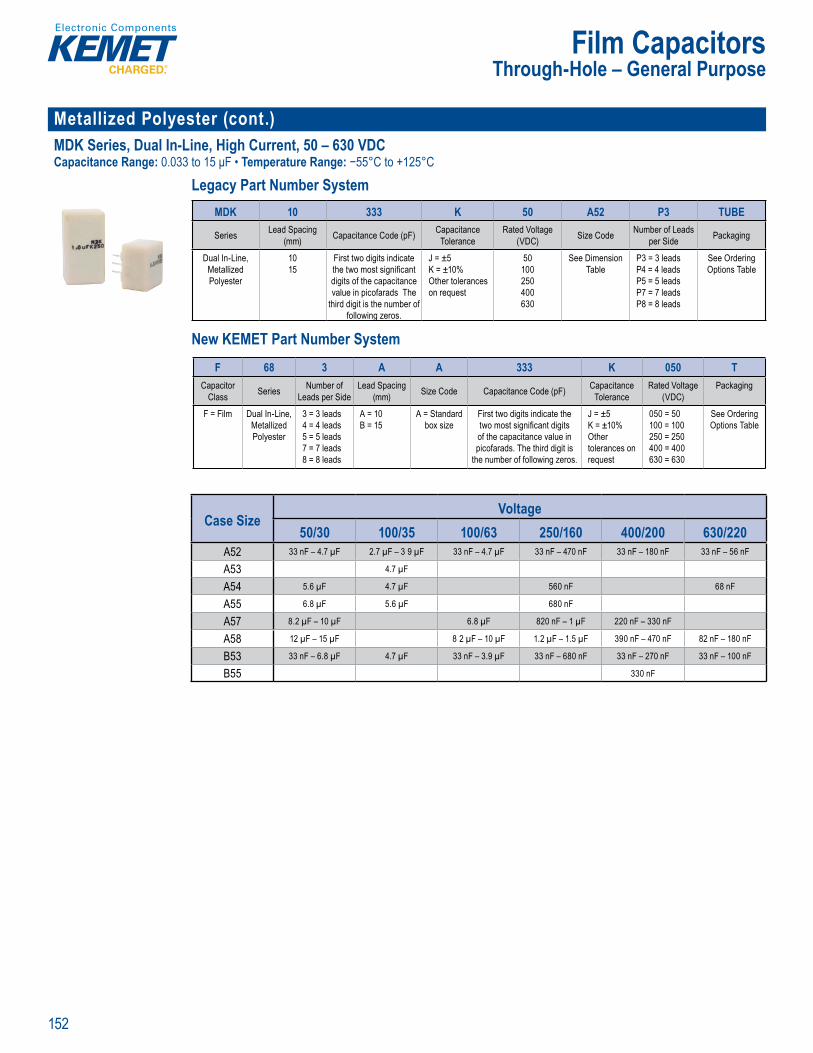
152
Film Capacitors
Metallized Polyester (cont.)MDK Series, Dual In-Line, High Current, 50 – 630 VDCCapacitance Range: 0.033 to 15 μF • Temperature Range: −55°C to +125°C
Legacy Part Number System
Legacy Part Number System
MDK 10 333 K 50 A52 P3 TUBE
Series Lead Spacing (mm) Capacitance Code (pF) Capacitance
ToleranceRated Voltage
(VDC) Size Code Number of Leads per Side Packaging
Dual In-Line, Metallized Polyester
1015
First two digits indicate the two most signifi cant digits of the capacitance value in picofarads The
third digit is the number of following zeros.
J = ±5K = ±10% Other tolerances on request
50100250400630
See Dimension Table
P3 = 3 leadsP4 = 4 leadsP5 = 5 leadsP7 = 7 leadsP8 = 8 leads
See Ordering Options Table
New KEMET Part Number System
L gac Part Numbe System
S rie Sp nc cit Vo ) z Co r o
k g n
l In L
P y ste
10 First two dig t ind c te
d ts f t capacitanc l i ad T
hird d it is the numb r o f l win zeros
±5
Ot er
50
2
6
e Dim nsi = 3 ead
P5 5 l adsP l dP8 8 l ads
e Orderin
New KEME Part Number System
F 68 3 A A 333 K 050 TCapacitor
Class Series Number of Leads per Side
Lead Spacing(mm) Size Code Capacitance Code (pF) Capacitance
ToleranceRated Voltage
(VDC)Packaging
F = Film Dual In-Line,Metallized Polyester
3 = 3 leads4 = 4 leads5 = 5 leads7 = 7 leads8 = 8 leads
A = 10B = 15
A = Standard box size
First two digits indicate the two most signifi cant digits of the capacitance value in picofarads. The third digit is
the number of following zeros.
J = ±5K = ±10% Other tolerances on request
050 = 50100 = 100250 = 250400 = 400630 = 630
See Ordering Options Table
Case SizeVoltage
50/30 100/35 100/63 250/160 400/200 630/220A52 33 nF – 4.7 µF 2.7 µF – 3 9 µF 33 nF – 4.7 µF 33 nF – 470 nF 33 nF – 180 nF 33 nF – 56 nF
A53 4.7 µF
A54 5.6 µF 4.7 µF 560 nF 68 nF
A55 6.8 µF 5.6 µF 680 nF
A57 8.2 µF – 10 µF 6.8 µF 820 nF – 1 µF 220 nF – 330 nF
A58 12 µF – 15 µF 8 2 µF – 10 µF 1.2 µF – 1.5 µF 390 nF – 470 nF 82 nF – 180 nF
B53 33 nF – 6.8 µF 4.7 µF 33 nF – 3.9 µF 33 nF – 680 nF 33 nF – 270 nF 33 nF – 100 nF
B55 330 nF
Through-Hole – General Purpose

153
Film Capacitors
Metallized Paper & Polyphenylene SulfidePME261 Series Impregnated Paper, 10.2 – 25.4 mm Lead Spacing, 400 – 1,000 VDCCapacitance Range: 0.001 to 1 µF • Temperature Range: −40°C to +70°C AC app & −40°C to +100°C DC app
Legacy Part Number System
• Climatic c T Excellent self-healing p ope ti s. Ensures on
d t t • Good es stance o ionizat on due to im r gnated dielectric
Legacy Part Number System
PME261 K A 5100 K R30
Series Rated Voltage (VAC) Lead Spacing (mm) Capacitance Code (pF) CapacitanceTolerance Packaging
Metallized Paper K = 220E = 300J = 500
A = 10 2B = 15.2C = 20.3E = 25.4
The last three digits represent signifi cant
fi gures First digit specifi es the total
number of digits in the capacitiance value.
J = ±5% K = ±10% M = ±20%
See Ordering Options Table
New KEMET Part Number System
Tape nd
s bj cted to frequent ove -volt ges es o io iz on e ted tr
L a y
Tolerance
E 30J = 50
B 5 2C = 0 3E = 2 4
pr sent i n fi cant fi gures First d git spec fi es the total mb r of d it in th
capac ti nce value
±1 %
M = ± 0%
Opti n Tab e
New KEMET Part Number System
P 561 H E 103 K 220 A
Capacitor Class Series Lead Spacing (mm) Size Code Capacitance Code (pF) Capacitance
ToleranceRated Voltage
(VAC) Packaging
P = Paper Metallized Paper
General Purpose
H = 10.2Q = 15.2C = 20.3E = 25.4
See Dimension
Table
First two digits indicate the two most signifi cant digits of the capacitance value in picofarads. The third digit is
the number of following zeroes.
J = ±5% K = ±10% M = ±20%
220 = 220300 = 300500 = 500
See Ordering Options Table
Case SizeVoltage
400/220 630/300 1,000/50010.2 – 13.5 x 10.5 x 5.1 15 nF – 22 nF 10 nF – 15 nF 4.7 nF – 6.8 nF
10.2 – 13.5 x 7.5 x 3.9 8.2 nF – 10 nF 1 nF – 6.8 nF 1 nF – 3.3 nF
15.2 – 18.5 x 10.5 x 5.2 33 nF – 47 nF 22 nF – 33 nF 10 nF – 15 nF
15.2 – 18.5 x 13 x 7.3 68 nF – 100 nF 47 nF – 68 nF 22 nF
15.2 – 18.5 x 13.5 x 7.8 33 nF
20.3 – 24 x 14 x 7.6 150 nF 100 nF 47 nF
20.3 – 24 x 15 x 9 150 nF 68 nF
20.3 – 24 x 16.5 x 11.3 330 nF 100 nF
20.3 – 24 x 14 x 8.4 220 nF
25.4 – 30.5 x 17.3 x 10.6 470 nF
25.4 – 30.5 x 22 x 15.3 680 nF – 1 µF
Through-Hole – General Purpose
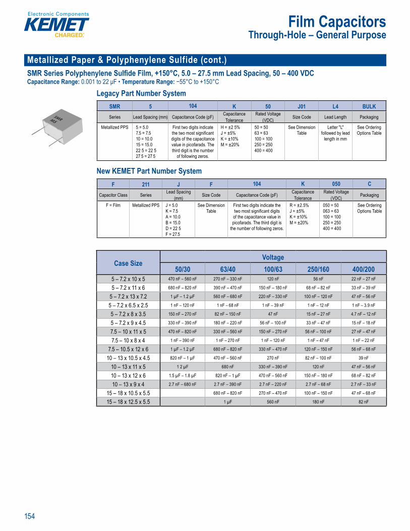
154
Film Capacitors
Metallized Paper & Polyphenylene Sulfide (cont.)SMR Series Polyphenylene Sulfide Film, +150°C, 5.0 – 27.5 mm Lead Spacing, 50 – 400 VDCCapacitance Range: 0.001 to 22 μF • Temperature Range: −55°C to +150°C
Legacy Part Number System
p n l n r e i 2 R HS Comp iant and ead f ee erm na ions Ca e ory temp ature r ge 55 to 5 C t t p
Legacy Part Number System
SMR 5 104 K 50 J01 L4 BULKSeries Lead Spacing (mm) Capacitance Code (pF) Capacitance
ToleranceRated Voltage
(VDC) Size Code Lead Length Packaging
Metallized PPS 5 = 5.07.5 = 7.510 = 10.015 = 15.022 5 = 22 527 5 = 27 5
First two digits indicate the two most signifi cant digits of the capacitance value in picofarads. The third digit is the number
of following zeros.
H = ±2 5%J = ±5% K = ±10% M = ±20%
50 = 5063 = 63100 = 100250 = 250400 = 400
See Dimension Table
Letter "L" followed by lead
length in mm
See Ordering Options Table
New KEMET Part Number System
R HS Comp iant and ead f ee term nations
• Rate temperat r +125 C
L g a Nu e y
SMR 1 4 K J 1 L4 BULKS i L d Sp i ( C p it C d pF C p it
T lt d lt
DC Si C d L d L t P k i
M t lli d PPS 5 57 5 7 51 115 1522 5 22 527 5 27 5
Fi t t di it i di t t t t i i c t di it f t p it
l i pi f r d T t i d di it i t b
f l i
H 2 5 5
K 1 M 2
5 53 3
1 125 25
S Di i T bl
L tt L f ll d by l d
l gt i
S O d i Opti T bl
New KEME Part Number System
F 211 J F 104 K 050 C
Capacitor Class Series Lead Spacing (mm) Size Code Capacitance Code (pF) Capacitance
ToleranceRated Voltage
(VDC) Packaging
F = Film Metallized PPS J = 5.0K = 7.5A = 10.0B = 15.0D = 22 5F = 27.5
See Dimension Table
First two digits indicate the two most signifi cant digits of the capacitance value in picofarads. The third digit is
the number of following zeros.
R = ±2.5%J = ±5% K = ±10% M = ±20%
050 = 50063 = 63100 = 100250 = 250400 = 400
See Ordering Options Table
Case SizeVoltage
50/30 63/40 100/63 250/160 400/2005 – 7.2 x 10 x 5 470 nF – 560 nF 270 nF – 330 nF 120 nF 56 nF 22 nF – 27 nF
5 – 7.2 x 11 x 6 680 nF – 820 nF 390 nF – 470 nF 150 nF – 180 nF 68 nF – 82 nF 33 nF – 39 nF
5 – 7.2 x 13 x 7.2 1 µF – 1.2 µF 560 nF – 680 nF 220 nF – 330 nF 100 nF – 120 nF 47 nF – 56 nF
5 – 7.2 x 6.5 x 2.5 1 nF – 120 nF 1 nF – 68 nF 1 nF – 39 nF 1 nF – 12 nF 1 nF – 3.9 nF
5 – 7.2 x 8 x 3.5 150 nF – 270 nF 82 nF – 150 nF 47 nF 15 nF – 27 nF 4.7 nF – 12 nF
5 – 7.2 x 9 x 4.5 330 nF – 390 nF 180 nF – 220 nF 56 nF – 100 nF 33 nF – 47 nF 15 nF – 18 nF
7.5 – 10 x 11 x 5 470 nF – 820 nF 330 nF – 560 nF 150 nF – 270 nF 56 nF – 100 nF 27 nF – 47 nF
7.5 – 10 x 8 x 4 1 nF – 390 nF 1 nF – 270 nF 1 nF – 120 nF 1 nF – 47 nF 1 nF – 22 nF
7.5 – 10.5 x 12 x 6 1 µF – 1.2 µF 680 nF – 820 nF 330 nF – 470 nF 120 nF – 150 nF 56 nF – 68 nF
10 – 13 x 10.5 x 4.5 820 nF – 1 µF 470 nF – 560 nF 270 nF 82 nF – 100 nF 39 nF
10 – 13 x 11 x 5 1 2 µF 680 nF 330 nF – 390 nF 120 nF 47 nF – 56 nF
10 – 13 x 12 x 6 1.5 µF – 1.8 µF 820 nF – 1 µF 470 nF – 560 nF 150 nF – 180 nF 68 nF – 82 nF
10 – 13 x 9 x 4 2.7 nF – 680 nF 2.7 nF – 390 nF 2.7 nF – 220 nF 2.7 nF – 68 nF 2.7 nF – 33 nF
15 – 18 x 10.5 x 5.5 680 nF – 820 nF 270 nF – 470 nF 100 nF – 150 nF 47 nF – 68 nF
15 – 18 x 12.5 x 5.5 1 µF 560 nF 180 nF 82 nF
Through-Hole – General Purpose
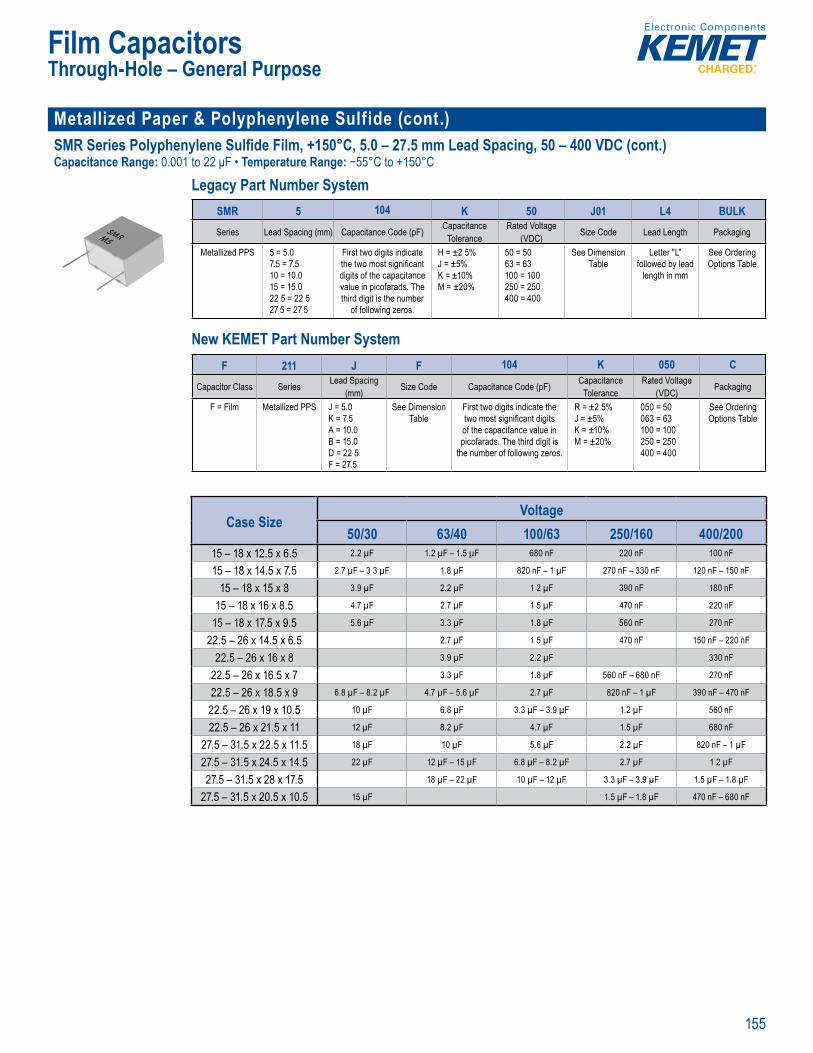
155
Film Capacitors
Metallized Paper & Polyphenylene Sulfide (cont.)SMR Series Polyphenylene Sulfide Film, +150°C, 5.0 – 27.5 mm Lead Spacing, 50 – 400 VDC (cont.)Capacitance Range: 0.001 to 22 μF • Temperature Range: −55°C to +150°C
Legacy Part Number System
apac ta ead pa
p n l n r e i 2 R HS Comp iant and ead f ee erm na ions Ca e ory temp ature r ge 55 to 5 C t t p
Legacy Part Number System
SMR 5 104 K 50 J01 L4 BULKSeries Lead Spacing (mm) Capacitance Code (pF) Capacitance
ToleranceRated Voltage
(VDC) Size Code Lead Length Packaging
Metallized PPS 5 = 5.07.5 = 7.510 = 10.015 = 15.022 5 = 22 527 5 = 27 5
First two digits indicate the two most signifi cant digits of the capacitance value in picofarads. The third digit is the number
of following zeros.
H = ±2 5%J = ±5% K = ±10% M = ±20%
50 = 5063 = 63100 = 100250 = 250400 = 400
See Dimension Table
Letter "L" followed by lead
length in mm
See Ordering Options Table
New KEMET Part Number System
Lead pa
R HS Comp iant and ead f ee term nations
• Rate temperat r +125 C
L g a Nu e y
SMR 1 4 K J 1 L4 BULKS i L d Sp i ( C p it C d pF C p it
T lt d lt
DC Si C d L d L t P k i
M t lli d PPS 5 57 5 7 51 115 1522 5 22 527 5 27 5
Fi t t di it i di t t t t i i c t di it f t p it
l i pi f r d T t i d di it i t b
f l i
H 2 5 5
K 1 M 2
5 53 3
1 125 25
S Di i T bl
L tt L f ll d by l d
l gt i
S O d i Opti T bl
New KEME Part Number System
F 211 J F 104 K 050 C
Capacitor Class Series Lead Spacing (mm) Size Code Capacitance Code (pF) Capacitance
ToleranceRated Voltage
(VDC) Packaging
F = Film Metallized PPS J = 5.0K = 7.5A = 10.0B = 15.0D = 22 5F = 27.5
See Dimension Table
First two digits indicate the two most signifi cant digits of the capacitance value in picofarads. The third digit is
the number of following zeros.
R = ±2.5%J = ±5% K = ±10% M = ±20%
050 = 50063 = 63100 = 100250 = 250400 = 400
See Ordering Options Table
Case SizeVoltage
50/30 63/40 100/63 250/160 400/20015 – 18 x 12.5 x 6.5 2.2 µF 1.2 µF – 1.5 µF 680 nF 220 nF 100 nF
15 – 18 x 14.5 x 7.5 2.7 µF – 3 3 µF 1.8 µF 820 nF – 1 µF 270 nF – 330 nF 120 nF – 150 nF
15 – 18 x 15 x 8 3.9 µF 2.2 µF 1 2 µF 390 nF 180 nF
15 – 18 x 16 x 8.5 4.7 µF 2.7 µF 1 5 µF 470 nF 220 nF
15 – 18 x 17.5 x 9.5 5.6 µF 3.3 µF 1.8 µF 560 nF 270 nF
22.5 – 26 x 14.5 x 6.5 2.7 µF 1 5 µF 470 nF 150 nF – 220 nF
22.5 – 26 x 16 x 8 3.9 µF 2.2 µF 330 nF
22.5 – 26 x 16.5 x 7 3.3 µF 1.8 µF 560 nF – 680 nF 270 nF
22.5 – 26 x 18.5 x 9 6.8 µF – 8.2 µF 4.7 µF – 5.6 µF 2.7 µF 820 nF – 1 µF 390 nF – 470 nF
22.5 – 26 x 19 x 10.5 10 µF 6.8 µF 3.3 µF – 3.9 µF 1.2 µF 560 nF
22.5 – 26 x 21.5 x 11 12 µF 8.2 µF 4.7 µF 1.5 µF 680 nF
27.5 – 31.5 x 22.5 x 11.5 18 µF 10 µF 5.6 µF 2.2 µF 820 nF – 1 µF
27.5 – 31.5 x 24.5 x 14.5 22 µF 12 µF – 15 µF 6.8 µF – 8.2 µF 2.7 µF 1 2 µF
27.5 – 31.5 x 28 x 17.5 18 µF – 22 µF 10 µF – 12 µF 3.3 µF – 3.9 µF 1.5 µF – 1.8 µF
27.5 – 31.5 x 20.5 x 10.5 15 µF 1.5 µF – 1.8 µF 470 nF – 680 nF
Through-Hole – General Purpose
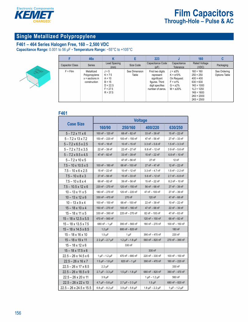
156
Film Capacitors
Single Metallized Polypropylene F461 – 464 Series Halogen Free, 160 – 2,500 VDCCapacitance Range: 0.001 to 56 μF • Temperature Range: −55°C to +105°C
Part Number S stem
F 46x K E 223 J 160 CCapacitor Class Series Lead Spacing
(mm) Size Code Capacitance Code (pF)
CapacitanceTolerance
Rated Voltage (VDC) Packaging
F = Film Metallized Polypropylene x = sections in construction
J = 5K = 7 5A = 10B = 15D = 22.5F = 27 5R = 37.5
See Dimension Table
First two digits represent signifi cant
fi gures. Third digit specifi es
number of zeros.
J = ±5%K = ±10%On Request:F = ±1% G = ±2% M = ±20%
160 = 160250 = 250400 = 400630 = 6301K0 = 10001L2 = 12501K6 = 16002K0 = 20002K5 = 2500
See Ordering Options Table
F461
Case SizeVoltage
160/90 250/160 400/220 630/2505 – 7.2 x 11 x 6 100 nF – 120 nF 68 nF – 82 nF 33 nF – 39 nF 15 nF – 22 nF
5 – 7.2 x 13 x 7.2 150 nF – 220 nF 100 nF – 150 nF 47 nF – 56 nF 27 nF – 33 nF
5 – 7.2 x 6.5 x 2.5 10 nF – 18 nF 10 nF – 15 nF 3.3 nF – 5.6 nF 1.5 nF – 3.3 nF
5 – 7.2 x 7.5 x 3.5 22 nF – 39 nF 22 nF – 27 nF 6.8 nF – 12 nF 3 9 nF – 5.6 nF
5 – 7.2 x 9.5 x 4.5 47 nF – 82 nF 33 nF – 39 nF 15 nF – 22 nF 6.8 nF – 10 nF
5 – 7.2 x 10 x 5 47 nF – 56 nF 27 nF 12 nF
7.5 – 10 x 10.5 x 5 100 nF – 180 nF 68 nF – 100 nF 27 nF – 47 nF 12 nF – 22 nF
7.5 – 10 x 6 x 2.5 15 nF – 22 nF 10 nF – 12 nF 3.3 nF – 4.7 nF 1.5 nF – 2.2 nF
7.5 – 10 x 8 x 3 27 nF – 56 nF 15 nF – 33 nF 5.6 nF – 12 nF 2.7 nF – 6.8 nF
7.5 – 10 x 8 x 4 68 nF – 82 nF 39 nF – 56 nF 15 nF – 22 nF 8.2 nF – 10 nF
7.5 – 10.5 x 12 x 6 220 nF – 270 nF 120 nF – 150 nF 56 nF – 68 nF 27 nF – 39 nF
10 – 13 x 11 x 5 180 nF – 270 nF 120 nF – 220 nF 47 nF – 100 nF 27 nF – 39 nF
10 – 13 x 12 x 6 330 nF – 470 nF 270 nF 120 nF 47 nF – 68 nF
10 – 13 x 9 x 4 100 nF – 150 nF 68 nF – 100 nF 22 nF – 39 nF 10 nF – 22 nF
15 – 18 x 10 x 4 150 nF – 270 nF 100 nF – 180 nF 47 nF – 68 nF 22 nF – 39 nF
15 – 18 x 11 x 5 330 nF – 390 nF 220 nF – 270 nF 82 nF – 100 nF 47 nF – 63 nF
15 – 18 x 12.5 x 5.5 470 nF – 560 nF 120 nF – 150 nF 68 nF – 82 nF
15 – 18 x 13.5 x 7.5 680 nF – 1 µF 390 nF – 560 nF 180 nF – 270 nF 100 nF – 150 nF
15 – 18 x 14.5 x 8.5 1.2 µF 680 nF – 820 nF 180 nF
15 – 18 x 16 x 10 1.5 µF 1 µF 390 nF – 470 nF 220 nF
15 – 18 x 19 x 11 2 2 µF – 2.7 µF 1.2 µF – 1.8 µF 560 nF – 820 nF 270 nF – 390 nF
15 – 18 x 12 x 6 330 nF
15 – 18 x 17.5 x 6 330 nF
22.5 – 26 x 14.5 x 6 1 µF – 1.2 µF 470 nF – 680 nF 220 nF – 330 nF 100 nF – 150 nF
22.5 – 26 x 16 x 7 1 5 µF – 1.8 µF 820 nF – 1 µF 390 nF – 470 nF 180 nF – 220 nF
22.5 – 26 x 17 x 8.5 2.2 µF 330 nF
22.5 – 26 x 18.5 x 9 2.7 µF – 3.3 µF 1.5 µF – 1.8 µF 680 nF – 820 nF 390 nF – 470 nF
22.5 – 26 x 20 x 11 3 9 µF 1 µF – 1.2 µF 560 nF
22.5 – 26 x 22 x 13 4.7 µF – 5.6 µF 2.7 µF – 3 3 µF 1.5 µF 680 nF – 820 nF
22.5 – 26 x 24.5 x 15.5 6.8 µF – 8.2 µF 3.9 µF – 5.6 µF 1.8 µF – 2.2 µF 1 µF – 1.2 µF
Through-Hole – Pulse & AC
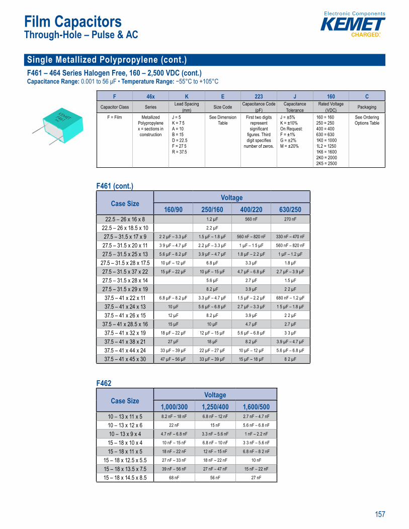
157
Film Capacitors
Single Metallized Polypropylene (cont.) F461 – 464 Series Halogen Free, 160 – 2,500 VDC (cont.)Capacitance Range: 0.001 to 56 μF • Temperature Range: −55°C to +105°C
g y Rated tem
Part Number S stem
F 46x K E 223 J 160 CCapacitor Class Series Lead Spacing
(mm) Size Code Capacitance Code (pF)
CapacitanceTolerance
Rated Voltage (VDC) Packaging
F = Film Metallized Polypropylene x = sections in construction
J = 5K = 7 5A = 10B = 15D = 22.5F = 27 5R = 37.5
See Dimension Table
First two digits represent signifi cant
fi gures. Third digit specifi es
number of zeros.
J = ±5%K = ±10%On Request:F = ±1% G = ±2% M = ±20%
160 = 160250 = 250400 = 400630 = 6301K0 = 10001L2 = 12501K6 = 16002K0 = 20002K5 = 2500
See Ordering Options Table
F461 (cont.)
Case SizeVoltage
160/90 250/160 400/220 630/25022.5 – 26 x 16 x 8 1.2 µF 560 nF 270 nF
22.5 – 26 x 18.5 x 10 2.2 µF
27.5 – 31.5 x 17 x 9 2 2 µF – 3.3 µF 1.5 µF – 1.8 µF 560 nF – 820 nF 330 nF – 470 nF
27.5 – 31.5 x 20 x 11 3 9 µF – 4.7 µF 2.2 µF – 3.3 µF 1 µF – 1 5 µF 560 nF – 820 nF
27.5 – 31.5 x 25 x 13 5.6 µF – 8.2 µF 3.9 µF – 4.7 µF 1.8 µF – 2.2 µF 1 µF – 1.2 µF
27.5 – 31.5 x 28 x 17.5 10 µF – 12 µF 6.8 µF 3.3 µF 1.8 µF
27.5 – 31.5 x 37 x 22 15 µF – 22 µF 10 µF – 15 µF 4.7 µF – 6.8 µF 2.7 µF – 3.9 µF
27.5 – 31.5 x 28 x 14 5.6 µF 2.7 µF 1.5 µF
27.5 – 31.5 x 29 x 19 8.2 µF 3.9 µF 2 2 µF
37.5 – 41 x 22 x 11 6.8 µF – 8.2 µF 3.3 µF – 4.7 µF 1.5 µF – 2.2 µF 680 nF – 1.2 µF
37.5 – 41 x 24 x 13 10 µF 5.6 µF – 6.8 µF 2.7 µF – 3.3 µF 1 5 µF – 1.8 µF
37.5 – 41 x 26 x 15 12 µF 8.2 µF 3.9 µF 2 2 µF
37.5 – 41 x 28.5 x 16 15 µF 10 µF 4.7 µF 2.7 µF
37.5 – 41 x 32 x 19 18 µF – 22 µF 12 µF – 15 µF 5.6 µF – 6.8 µF 3 3 µF
37.5 – 41 x 38 x 21 27 µF 18 µF 8.2 µF 3.9 µF – 4.7 µF
37.5 – 41 x 44 x 24 33 µF – 39 µF 22 µF – 27 µF 10 µF – 12 µF 5.6 µF – 6.8 µF
37.5 – 41 x 45 x 30 47 µF – 56 µF 33 µF – 39 µF 15 µF – 18 µF 8 2 µF
F462
Case SizeVoltage
1,000/300 1,250/400 1,600/50010 – 13 x 11 x 5 8.2 nF – 18 nF 6.8 nF – 12 nF 2.7 nF – 4.7 nF
10 – 13 x 12 x 6 22 nF 15 nF 5.6 nF – 6.8 nF
10 – 13 x 9 x 4 4.7 nF – 6.8 nF 3.3 nF – 5.6 nF 1 nF – 2.2 nF
15 – 18 x 10 x 4 10 nF – 15 nF 6.8 nF – 10 nF 3 3 nF – 5.6 nF
15 – 18 x 11 x 5 18 nF – 22 nF 12 nF – 15 nF 6.8 nF – 8 2 nF
15 – 18 x 12.5 x 5.5 27 nF – 33 nF 18 nF – 22 nF 10 nF
15 – 18 x 13.5 x 7.5 39 nF – 56 nF 27 nF – 47 nF 15 nF – 22 nF
15 – 18 x 14.5 x 8.5 68 nF 56 nF 27 nF
Through-Hole – Pulse & AC
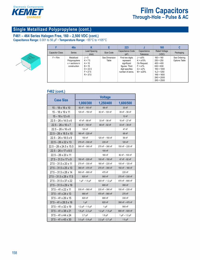
158
Film Capacitors
Single Metallized Polypropylene (cont.) F461 – 464 Series Halogen Free, 160 – 2,500 VDC (cont.)Capacitance Range: 0.001 to 56 μF • Temperature Range: −55°C to +105°C
Part Number S stem
F 46x K E 223 J 160 CCapacitor Class Series Lead Spacing
(mm) Size Code Capacitance Code (pF)
CapacitanceTolerance
Rated Voltage (VDC) Packaging
F = Film Metallized Polypropylene x = sections in construction
J = 5K = 7 5A = 10B = 15D = 22.5F = 27 5R = 37.5
See Dimension Table
First two digits represent signifi cant
fi gures. Third digit specifi es
number of zeros.
J = ±5%K = ±10%On Request:F = ±1% G = ±2% M = ±20%
160 = 160250 = 250400 = 400630 = 6301K0 = 10001L2 = 12501K6 = 16002K0 = 20002K5 = 2500
See Ordering Options Table
F462 (cont.)
Case SizeVoltage
1,000/300 1,250/400 1,600/50015 – 18 x 16 x 10 82 nF – 100 nF 68 nF 33 nF
15 – 18 x 19 x 11 120 nF – 150 nF 82 nF – 120 nF 39 nF – 56 nF
15 – 18 x 12 x 6 12 nF
22.5 – 26 x 14.5 x 6 47 nF – 68 nF 33 nF – 56 nF 15 nF – 27 nF
22.5 – 26 x 16 x 7 82 nF – 100 nF 68 nF – 82 nF 33 nF – 39 nF
22.5 – 26 x 16 x 8 120 nF 47 nF
22.5 – 26 x 18.5 x 10 180 nF – 220 nF 68 nF
22.5 – 26 x 18.5 x 9 150 nF 120 nF – 150 nF 56 nF
22.5 – 26 x 22 x 13 270 nF – 330 nF 220 nF 120 nF
22.5 – 26 x 24.5 x 15.5 390 nF – 560 nF 270 nF – 390 nF 150 nF – 220 nF
22.5 – 26 x 17 x 8.5 100 nF
22.5 – 26 x 20 x 11 180 nF 82 nF – 100 nF
27.5 – 31.5 x 17 x 9 150 nF – 220 nF 100 nF – 150 nF 47 nF – 82 nF
27.5 – 31.5 x 20 x 11 270 nF – 330 nF 180 nF – 220 nF 100 nF – 120 nF
27.5 – 31.5 x 25 x 13 390 nF – 470 nF 270 nF – 390 nF 150 nF – 180 nF
27.5 – 31.5 x 28 x 14 560 nF – 680 nF 470 nF 220 nF
27.5 – 31.5 x 28 x 17.5 820 nF 560 nF 270 nF – 330 nF
27.5 – 31.5 x 37 x 22 1 µF – 1.5 µF 820 nF – 1.2 µF 470 nF – 680 nF
27.5 – 31.5 x 29 x 19 680 nF 390 nF
37.5 – 41 x 22 x 11 330 nF – 560 nF 220 nF – 390 nF 150 nF – 220 nF
37.5 – 41 x 24 x 13 680 nF 470 nF – 560 nF 270 nF
37.5 – 41 x 26 x 15 820 nF 680 nF 330 nF
37.5 – 41 x 28.5 x 16 1 µF 820 nF 390 nF – 470 nF
37.5 – 41 x 32 x 19 1.2 µF – 1 5 µF 1 µF 560 nF
37.5 – 41 x 38 x 21 1.8 µF – 2.2 µF 1.2 µF – 1.5 µF 680 nF – 820 nF
37.5 – 41 x 44 x 24 2.7 µF 1.8 µF 1 µF – 1.2 µF
37.5 – 41 x 45 x 30 3.3 µF – 3.9 µF 2.2 µF – 2.7 µF 1 5 µF
Through-Hole – Pulse & AC

159
Film Capacitors
Single Metallized Polypropylene (cont.) F461 – 464 Series Halogen Free, 160 – 2,500 VDC (cont.)Capacitance Range: 0.001 to 56 μF • Temperature Range: −55°C to +105°C
g y Rated tem
Part Number S stem
F 46x K E 223 J 160 CCapacitor Class Series Lead Spacing
(mm) Size Code Capacitance Code (pF)
CapacitanceTolerance
Rated Voltage (VDC) Packaging
F = Film Metallized Polypropylene x = sections in construction
J = 5K = 7 5A = 10B = 15D = 22.5F = 27 5R = 37.5
See Dimension Table
First two digits represent signifi cant
fi gures. Third digit specifi es
number of zeros.
J = ±5%K = ±10%On Request:F = ±1% G = ±2% M = ±20%
160 = 160250 = 250400 = 400630 = 6301K0 = 10001L2 = 12501K6 = 16002K0 = 20002K5 = 2500
See Ordering Options Table
F463
Case SizeVoltage
1,250/500 1,600/650 2,000/70010 – 13 x 11 x 5 2.7 nF – 4.7 nF
10 – 13 x 12 x 6 5.6 nF
10 – 13 x 9 x 4 1 nF – 2 2 nF
15 – 18 x 10 x 4 4.7 nF – 6.8 nF 3.3 nF – 4.7 nF 1 nF – 2 2 nF
15 – 18 x 11 x 5 8.2 nF – 10 nF 5.6 nF – 6.8 nF 2.7 nF – 3.9 nF
15 – 18 x 12 x 6 15 nF 10 nF
15 – 18 x 12.5 x 5.5 12 nF 8.2 nF 4.7 nF – 5.6 nF
15 – 18 x 13.5 x 7.5 18 nF – 27 nF 12 nF – 15 nF 6.8 nF – 10 nF
15 – 18 x 14.5 x 8.5 33 nF 18 nF – 22 nF 12 nF
15 – 18 x 16 x 10 39 nF – 47 nF 27 nF 15 nF
15 – 18 x 19 x 11 56 nF – 68 nF 33 nF – 47 nF 18 nF – 27 nF
22.5 – 26 x 14.5 x 6 22 nF – 39 nF 15 nF – 27 nF 10 nF – 12 nF
22.5 – 26 x 16 x 7 47 nF – 56 nF 33 nF – 39 nF 15 nF – 18 nF
22.5 – 26 x 17 x 8.5 68 nF 47 nF 27 nF
22.5 – 26 x 18.5 x 10 100 nF 68 nF 33 nF – 39 nF
22.5 – 26 x 18.5 x 9 82 nF 56 nF
22.5 – 26 x 20 x 11 120 nF 82 nF 47 nF
22.5 – 26 x 22 x 13 150 nF – 180 nF 100 nF – 120 nF 56 nF – 68 nF
22.5 – 26 x 24.5 x 15.5 220 nF – 270 nF 150 nF – 180 nF 82 nF – 100 nF
22.5 – 26 x 16 x 8 22 nF
27.5 – 31.5 x 17 x 9 68 nF – 120 nF 47 nF – 82 nF 22 nF – 39 nF
27.5 – 31.5 x 20 x 11 150 nF – 180 nF 100 nF – 120 nF 47 nF – 68 nF
27.5 – 31.5 x 25 x 13 220 nF – 270 nF 150 nF – 180 nF 82 nF – 100 nF
27.5 – 31.5 x 28 x 14 330 nF 220 nF 120 nF
27.5 – 31.5 x 28 x 17.5 390 nF – 470 nF 270 nF 150 nF
27.5 – 31.5 x 37 x 22 560 nF – 820 nF 390 nF – 560 nF 220 nF – 330 nF
27.5 – 31.5 x 29 x 19 330 nF 180 nF
37.5 – 41 x 22 x 11 220 nF – 330 nF 150 nF – 220 nF 68 nF – 120 nF
37.5 – 41 x 24 x 13 390 nF 270 nF 150 nF
Through-Hole – Pulse & AC

160
Film Capacitors
Single Metallized Polypropylene (cont.) F461 – 464 Series Halogen Free, 160 – 2,500 VDC (cont.)Capacitance Range: 0.001 to 56 μF • Temperature Range: −55°C to +105°C
Part Number S stem
F 46x K E 223 J 160 CCapacitor Class Series Lead Spacing
(mm) Size Code Capacitance Code (pF)
CapacitanceTolerance
Rated Voltage (VDC) Packaging
F = Film Metallized Polypropylene x = sections in construction
J = 5K = 7 5A = 10B = 15D = 22.5F = 27 5R = 37.5
See Dimension Table
First two digits represent signifi cant
fi gures. Third digit specifi es
number of zeros.
J = ±5%K = ±10%On Request:F = ±1% G = ±2% M = ±20%
160 = 160250 = 250400 = 400630 = 6301K0 = 10001L2 = 12501K6 = 16002K0 = 20002K5 = 2500
See Ordering Options Table
F463 (cont.)
Case SizeVoltage
1,250/500 1,600/650 2,000/70037.5 – 41 x 26 x 15 470 nF 330 nF 180 nF
37.5 – 41 x 28.5 x 16 560 nF – 680 nF 390 nF 220 nF
37.5 – 41 x 32 x 19 820 nF 470 nF – 560 nF 270 nF – 330 nF
37.5 – 41 x 38 x 21 1 µF – 1.2 µF 680 nF – 820 nF 390 nF – 470 nF
37.5 – 41 x 44 x 24 1.5 µF 1 µF – 1.2 µF 560 nF
37.5 – 41 x 45 x 30 1.8 µF – 2.2 µF 1.5 µF 680 nF – 820 nF
F464
Case SizeVoltage
2,500/90015 – 18 x 10 x 4 1 nF – 2.2 nF
15 – 18 x 11 x 5 2.7 nF – 3.3 nF
15 – 18 x 12.5 x 5.5 3.9 nF – 4.7 nF
15 – 18 x 13.5 x 7.5 5.6 nF – 8.2 nF
15 – 18 x 14.5 x 8.5 10 nF
15 – 18 x 16 x 10 12 nF – 15 nF
15 – 18 x 19 x 11 18 nF – 22 nF
22.5 – 26 x 14.5 x 6 4.7 nF – 8.2 nF
22.5 – 26 x 16 x 7 10 nF – 12 nF
22.5 – 26 x 17 x 8.5 15 nF
22.5 – 26 x 18.5 x 9 18 nF – 22 nF
22.5 – 26 x 20 x 11 27 nF
22.5 – 26 x 22 x 13 33 nF
22.5 – 26 x 24.5 x 15.5 39 nF – 56 nF
27.5 – 31.5 x 17 x 9 15 nF – 27 nF
Case SizeVoltage
2,500/90027.5 – 31.5 x 20 x 11 33 nF – 39 nF
27.5 – 31.5 x 25 x 13 47 nF – 68 nF
27.5 – 31.5 x 28 x 14 82 nF
27.5 – 31.5 x 28 x 17.5 100 nF
27.5 – 31.5 x 29 x 19 120 nF
27.5 – 31.5 x 37 x 22 150 nF – 180 nF
37.5 – 41 x 22 x 11 47 nF – 68 nF
37.5 – 41 x 24 x 13 82 nF – 100 nF
37.5 – 41 x 26 x 15 120 nF
37.5 – 41 x 28.5 x 16 150 nF
37.5 – 41 x 32 x 19 180 nF – 220 nF
37.5 – 41 x 38 x 21 270 nF
37.5 – 41 x 44 x 24 330 nF – 390 nF
37.5 – 41 x 45 x 30 470 nF – 560 nF
Through-Hole – Pulse & AC

161
Film Capacitors
Single Metallized Polypropylene (cont.) R79 Series Radial, 5 mm Lead Spacing, 160 – 630 VDCCapacitance Range: 0.001 to 0.22 μF Temperature Range: −55°C to +105°C
p RoHS com
Part Num er System
R79 G C 2390 AA 40 KSeries Rated Voltage (VDC) Lead Spacing (mm) Capacitance Code
(pF) Packaging Internal Use Capacitance Tolerance
Metallized Polypropylene
G = 160I = 250M = 400P = 630
C = 5 The last three digits represent signifi cant
fi gures. The fi rst digit specifi es the total number of
zeros to be added.
See Ordering Options Table
4045
H = 2.5%J = ±5% K = ±10%
Case SizeVoltage
160/70 250/160 400/200 630/2205 – 7.2 x 10 x 5 82 nF – 100 nF 68 nF 18 nF – 22 nF 6.8 nF – 8.2 nF
5 – 7.2 x 11 x 6 120 nF – 150 nF 82 nF – 100 nF 27 nF – 33 nF 10 nF – 12 nF
5 – 7.2 x 13 x 7 2 180 nF – 220 nF 120 nF – 150 nF 39 nF – 47 nF 15 nF – 18 nF
5 – 7.2 x 7.5 x 3.5 39 nF 12 nF – 33 nF 3.9 nF – 10 nF 1 nF – 3.3 nF
5 – 7.2 x 9.5 x 4.5 47 nF – 68 nF 39 nF – 56 nF 12 nF – 15 nF 3 9 nF – 5.6 nF
R75 Series Radial, DC & Pulse Applications 160 – 2,000 VDC (Automotive Grade)Capacitance Range: 220 pF to 33 μF • Temperature Range: −55°C to +105°C
p c d S a i : 7 m li t c c t y p r t n empe n e f ˚C 05˚C RoHS c mp a ce ad-free te mi s T pe a d r e pac ccor IEC 0286 S -he l
O e e
welded to the meta ay r n he nds o th ci i n x
es s ant pl stic case wi thermo etting resin the L 4V r qu remen s. wo differ t wi in construc
see e m
motive r v c s le 22 5 ) and meet eman ci s
tio req
P t u b
R75 P N 2820 AA 30 KSeries Rated Voltage (VDC) Lead Spacing (mm) Capacitance Code
(pF) Packaging Internal Use CapacitanceTolerance
Metallized Polypropylene
G = 160I = 250M = 400P = 630Q = 1,000R = 1,250T = 1,600U = 2,000
D = 7.5F = 10I = 15N = 22.5R = 27 5W = 37.5
The last three digits represent signifi cant
fi gures. The fi rst digit specifi es the total number of
zeros to be added.
See Ordering Options Table
0010304050607080
J = ±5% K = ±10% M = ±20%
Case SizeVoltage
160/70 160/90 250/140 250/160 400/200 400/220 630/2207.5 – 10 x 10.5 x 5 120 nF – 150 nF 100 nF – 120 nF 100 nF – 120 nF 68 nF – 82 nF 33 nF – 47 nF 27 nF – 33 nF 15 nF – 18 nF
7.5 – 10 x 9 x 4 100 nF 68 nF – 82 nF 68 nF – 82 nF 27 nF – 56 nF 27 nF 10 nF – 22 nF 10 nF – 12 nF
7.5 – 10.5 x 12 x 6 180 nF – 220 nF 150 nF – 180 nF 150 nF – 180 nF 100 nF – 120 nF 56 nF – 68 nF 39 nF – 47 nF 22 nF – 27 nF
10 – 13 x 11 x 5 180 nF – 220 nF 120 nF – 150 nF 120 nF – 150 nF 82 nF – 100 nF 33 nF – 39 nF
10 – 13 x 12 x 6 270 nF – 330 nF 180 nF – 220 nF 180 nF – 220 nF 120 nF – 150 nF
10 – 13 x 9 x 4 120 nF – 150 nF 82 nF – 100 nF 82 nF – 100 nF 33 nF – 68 nF 15 nF – 27 nF
15 – 18 x 11 x 5 180 nF – 220 nF 120 nF – 220 nF 68 nF – 100 nF
15 – 18 x 12 x 13 680 nF 680 nF – 820 nF 330 nF
15 – 18 x 12 x 6 270 nF – 330 nF 270 nF – 330 nF 120 nF – 150 nF
15 – 18 x 12.5 x 9 470 nF – 560 nF 390 nF – 560 nF 220 nF – 270 nF
15 – 18 x 13.5 x 7.5 390 nF – 470 nF 390 nF – 560 nF 180 nF – 220 nF
Through-Hole – Pulse & AC

162
Film Capacitors
Single Metallized Polypropylene (cont.) R75 Series Radial, DC & Pulse Applications 160 – 2,000 VDC (Automotive Grade) (cont.)Capacitance Range: 220 pF to 33 μF • Temperature Range: −55°C to +105°C
22 5mm
P t u b
R75 P N 2820 AA 30 KSeries Rated Voltage (VDC) Lead Spacing (mm) Capacitance Code
(pF) Packaging Internal Use CapacitanceTolerance
Metallized Polypropylene
G = 160I = 250M = 400P = 630Q = 1,000R = 1,250T = 1,600U = 2,000
D = 7.5F = 10I = 15N = 22.5R = 27 5W = 37.5
The last three digits represent signifi cant
fi gures. The fi rst digit specifi es the total number of
zeros to be added.
See Ordering Options Table
0010304050607080
J = ±5% K = ±10% M = ±20%
Case SizeVoltage
160/90 250/160 400/22015 – 18 x 14.5 x 8.5 560 nF – 680 nF 680 nF 270 nF
15 – 18 x 16 x 10 820 nF – 1 µF 820 nF – 1 µF 330 nF – 470 nF
15 – 18 x 19 x 11 1.2 µF 560 nF
22.5 – 26.5 x 15 x 6 390 nF – 680 nF 180 nF – 330 nF
22.5 – 26.5 x 16 x 7 820 nF – 1 µF 820 nF – 1 µF 390 nF – 470 nF
22.5 – 26.5 x 17 x 8.5 1.2 µF 1.2 µF 560 nF
22.5 – 26.5 x 18.5 x 10 1.5 µF – 1.8 µF 1.5 µF – 1.8 µF 680 nF – 820 nF
22.5 – 26.5 x 20 x 11 2.2 µF 1 µF
22.5 – 26.5 x 22 x 13 2.7 µF – 3.3 µF 1.2 µF – 1.5 µF
27.5 – 32 x 17 x 9 1.5 µF – 1.8 µF 1 µF – 1.8 µF 560 nF – 820 nF
27.5 – 32 x 20 x 11 2.2 µF – 2.7 µF 2.2 µF – 2.7 µF 1 µF – 1.2 µF
27.5 – 32 x 22 x 13 3.3 µF – 3.9 µF 3.3 µF – 3.9 µF 1.5 µF – 1.8 µF
27.5 – 32 x 25 x 13 4.7 µF 4.7 µF 2.2 µF
27.5 – 32 x 28 x 14 5.6 µF 5.6 µF 2.7 µF
27.5 – 32 x 33 x 18 6.8 µF – 8.2 µF 6.8 µF – 8.2 µF 3.3 µF – 3.9 µF
27.5 – 32 x 37 x 22 10 µF – 12 µF 10 µF – 12 µF 4.7 µF – 5.6 µF
37.5 – 41.5 x 22 x 11 3.3 µF – 4.7 µF 3.3 µF – 4.7 µF 1.2 µF – 2.2 µF
37.5 – 41.5 x 24 x 13 5.6 µF 5.6 µF 2.7 µF
37.5 – 41.5 x 28.5 x 16 6.8 µF – 8.2 µF 6.8 µF – 8.2 µF 3.3 µF – 3.9 µF
37.5 – 41.5 x 32 x 19 10 µF – 12 µF 10 µF – 12 µF 4.7 µF – 6.8 µF
37.5 – 41.5 x 40 x 20 15 µF – 18 µF 15 µF – 18 µF 8.2 µF – 10 µF
37.5 – 41.5 x 44 x 24 22 µF 22 µF – 27 µF 12 µF
37.5 – 41.5 x 45 x 30 27 µF – 33 µF 33 µF 15 µF
Case SizeVoltage
630/250 1,000/4007.5 – 10 x 10.5 x 5 10 nF – 12 nF 3.9 nF – 5.6 nF
7.5 – 10 x 8 x 3 0 22 nF – 1 nF
7.5 – 10 x 9 x 4 3.3 nF – 8 2 nF 1.2 nF – 3.3 nF
7.5 – 10.5 x 12 x 6 15 nF – 18 nF 6.8 nF – 8.2 nF
Through-Hole – Pulse & AC
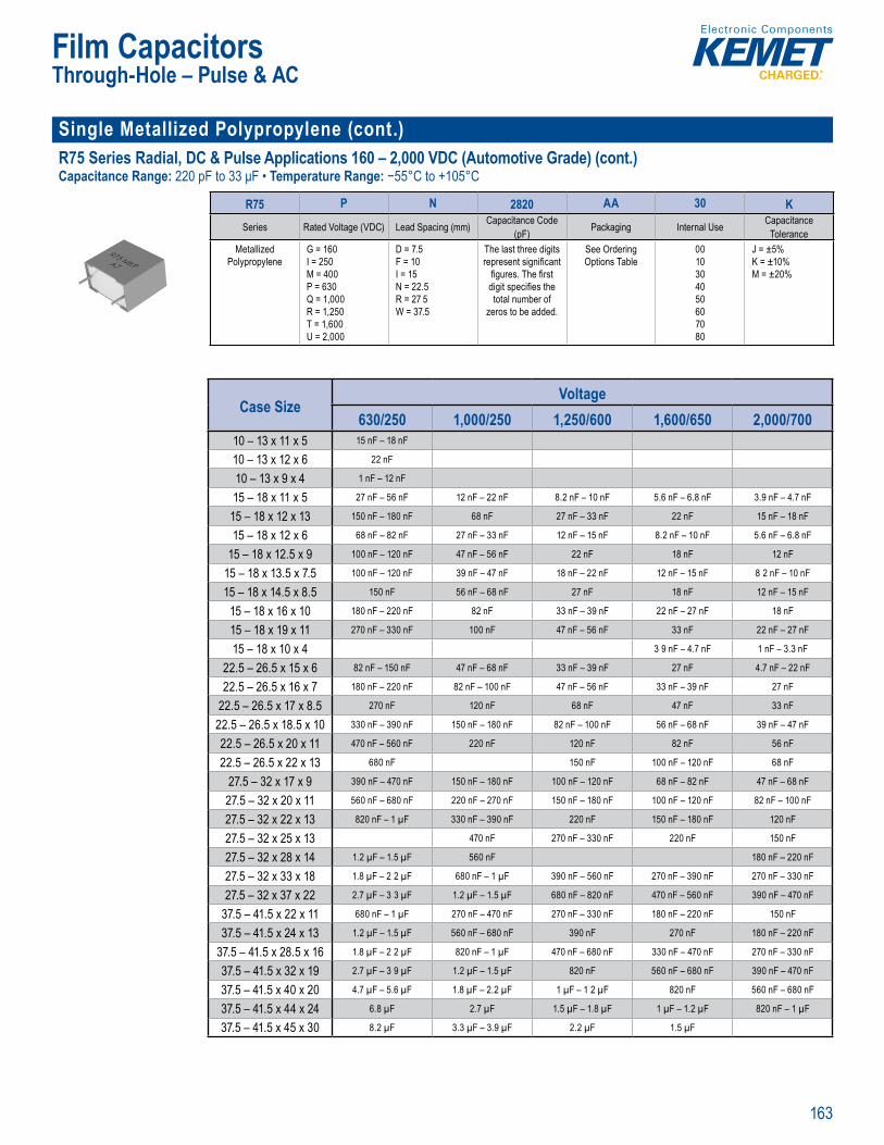
163
Film Capacitors
Single Metallized Polypropylene (cont.) R75 Series Radial, DC & Pulse Applications 160 – 2,000 VDC (Automotive Grade) (cont.)Capacitance Range: 220 pF to 33 μF • Temperature Range: −55°C to +105°C
• • Oper ting
22 5mm
P t u b
R75 P N 2820 AA 30 KSeries Rated Voltage (VDC) Lead Spacing (mm) Capacitance Code
(pF) Packaging Internal Use CapacitanceTolerance
Metallized Polypropylene
G = 160I = 250M = 400P = 630Q = 1,000R = 1,250T = 1,600U = 2,000
D = 7.5F = 10I = 15N = 22.5R = 27 5W = 37.5
The last three digits represent signifi cant
fi gures. The fi rst digit specifi es the total number of
zeros to be added.
See Ordering Options Table
0010304050607080
J = ±5% K = ±10% M = ±20%
Case SizeVoltage
630/250 1,000/250 1,250/600 1,600/650 2,000/70010 – 13 x 11 x 5 15 nF – 18 nF
10 – 13 x 12 x 6 22 nF
10 – 13 x 9 x 4 1 nF – 12 nF
15 – 18 x 11 x 5 27 nF – 56 nF 12 nF – 22 nF 8.2 nF – 10 nF 5.6 nF – 6.8 nF 3.9 nF – 4.7 nF
15 – 18 x 12 x 13 150 nF – 180 nF 68 nF 27 nF – 33 nF 22 nF 15 nF – 18 nF
15 – 18 x 12 x 6 68 nF – 82 nF 27 nF – 33 nF 12 nF – 15 nF 8.2 nF – 10 nF 5.6 nF – 6.8 nF
15 – 18 x 12.5 x 9 100 nF – 120 nF 47 nF – 56 nF 22 nF 18 nF 12 nF
15 – 18 x 13.5 x 7.5 100 nF – 120 nF 39 nF – 47 nF 18 nF – 22 nF 12 nF – 15 nF 8 2 nF – 10 nF
15 – 18 x 14.5 x 8.5 150 nF 56 nF – 68 nF 27 nF 18 nF 12 nF – 15 nF
15 – 18 x 16 x 10 180 nF – 220 nF 82 nF 33 nF – 39 nF 22 nF – 27 nF 18 nF
15 – 18 x 19 x 11 270 nF – 330 nF 100 nF 47 nF – 56 nF 33 nF 22 nF – 27 nF
15 – 18 x 10 x 4 3 9 nF – 4.7 nF 1 nF – 3.3 nF
22.5 – 26.5 x 15 x 6 82 nF – 150 nF 47 nF – 68 nF 33 nF – 39 nF 27 nF 4.7 nF – 22 nF
22.5 – 26.5 x 16 x 7 180 nF – 220 nF 82 nF – 100 nF 47 nF – 56 nF 33 nF – 39 nF 27 nF
22.5 – 26.5 x 17 x 8.5 270 nF 120 nF 68 nF 47 nF 33 nF
22.5 – 26.5 x 18.5 x 10 330 nF – 390 nF 150 nF – 180 nF 82 nF – 100 nF 56 nF – 68 nF 39 nF – 47 nF
22.5 – 26.5 x 20 x 11 470 nF – 560 nF 220 nF 120 nF 82 nF 56 nF
22.5 – 26.5 x 22 x 13 680 nF 150 nF 100 nF – 120 nF 68 nF
27.5 – 32 x 17 x 9 390 nF – 470 nF 150 nF – 180 nF 100 nF – 120 nF 68 nF – 82 nF 47 nF – 68 nF
27.5 – 32 x 20 x 11 560 nF – 680 nF 220 nF – 270 nF 150 nF – 180 nF 100 nF – 120 nF 82 nF – 100 nF
27.5 – 32 x 22 x 13 820 nF – 1 µF 330 nF – 390 nF 220 nF 150 nF – 180 nF 120 nF
27.5 – 32 x 25 x 13 470 nF 270 nF – 330 nF 220 nF 150 nF
27.5 – 32 x 28 x 14 1.2 µF – 1.5 µF 560 nF 180 nF – 220 nF
27.5 – 32 x 33 x 18 1.8 µF – 2 2 µF 680 nF – 1 µF 390 nF – 560 nF 270 nF – 390 nF 270 nF – 330 nF
27.5 – 32 x 37 x 22 2.7 µF – 3 3 µF 1.2 µF – 1.5 µF 680 nF – 820 nF 470 nF – 560 nF 390 nF – 470 nF
37.5 – 41.5 x 22 x 11 680 nF – 1 µF 270 nF – 470 nF 270 nF – 330 nF 180 nF – 220 nF 150 nF
37.5 – 41.5 x 24 x 13 1.2 µF – 1.5 µF 560 nF – 680 nF 390 nF 270 nF 180 nF – 220 nF
37.5 – 41.5 x 28.5 x 16 1.8 µF – 2 2 µF 820 nF – 1 µF 470 nF – 680 nF 330 nF – 470 nF 270 nF – 330 nF
37.5 – 41.5 x 32 x 19 2.7 µF – 3 9 µF 1.2 µF – 1.5 µF 820 nF 560 nF – 680 nF 390 nF – 470 nF
37.5 – 41.5 x 40 x 20 4.7 µF – 5.6 µF 1.8 µF – 2.2 µF 1 µF – 1 2 µF 820 nF 560 nF – 680 nF
37.5 – 41.5 x 44 x 24 6.8 µF 2.7 µF 1.5 µF – 1.8 µF 1 µF – 1.2 µF 820 nF – 1 µF
37.5 – 41.5 x 45 x 30 8.2 µF 3.3 µF – 3.9 µF 2.2 µF 1.5 µF
Through-Hole – Pulse & AC

164
Film Capacitors
Single Metallized Polypropylene (cont.) R74 Series Radial, AC Applications 250 – 900 VAC (Automotive Grade)Capacitance Range: 470 pF to 3.3 μF Temperature Range: −55°C to +105°C
22 5 mm
Pa t Num er System
R74 5 N 2180 AA 00 JSeries Rated Voltage (VAC) Lead Spacing (mm) Capacitance Code
(pF) Packaging Internal Use CapacitanceTolerance
Metallized Polypropylene
L = 250N = 4005 = 5006 = 6007 = 7009 = 900
F = 10I = 15N = 22.5R = 27 5W = 37.5
The last three digits represent signifi cant
fi gures. The fi rst digit specifi es the total number of
zeros to be added.
See Ordering Options Table
003060
J = ±5% K = ±10%
Case SizeVoltage
630/250 1,300/400 1,600/500 2,000/600 2,000/700 2,200/90010 – 13 x 11 x 5 15 nF – 18 nF 3.9 nF – 5.6 nF 2.2 nF – 2.7 nF 2.2 nF – 2.7 nF 2 2 nF – 2.7 nF
10 – 13 x 12 x 6 22 nF – 27 nF 6.8 nF – 8.2 nF 3.3 nF – 8.2 nF 3.3 nF – 8.2 nF 3 3 nF – 5.6 nF
10 – 13 x 9 x 4 10 nF – 12 nF 2.2 nF – 3.3 nF 1 nF – 1.8 nF 0.47 nF – 1.8 nF 0.47 nF – 1.8 nF
15 – 18 x 11 x 5 15 nF – 33 nF 6.8 nF – 10 nF 1.5 nF – 5.6 nF 3.9 nF – 4.7 nF 1 nF – 3.3 nF
15 – 18 x 12 x 13 82 nF – 100 nF 27 nF – 39 nF 15 nF – 22 nF 10 nF – 12 nF
15 – 18 x 12 x 6 39 nF – 47 nF 12 nF – 15 nF 6.8 nF – 10 nF 6.8 nF 3 9 nF – 5.6 nF
15 – 18 x 12.5 x 9 68 nF 22 nF 8.2 nF
15 – 18 x 13.5 x 7.5 56 nF – 68 nF 18 nF – 22 nF 12 nF – 15 nF 6.8 nF – 8 2 nF
15 – 18 x 14.5 x 8.5 82 nF – 100 nF 27 nF – 33 nF 18 nF 12 nF – 15 nF 10 nF
15 – 18 x 16 x 10 120 nF 39 nF – 47 nF 22 nF – 27 nF 18 nF 12 nF – 15 nF
15 – 18 x 19 x 11 150 nF 56 nF 33 nF 18 nF
15 – 18 x 10 x 4 1.5 nF – 4.7 nF 2.3 nF – 2.7 nF 0.47 nF – 2.2 nF
22.5 – 26.5 x 15 x 6 39 nF 18 nF – 22 nF 8.2 nF – 15 nF 1 nF – 6.8 nF
22.5 – 26.5 x 16 x 7 47 nF – 56 nF 27 nF – 33 nF 18 nF 8.2 nF – 10 nF
22.5 – 26.5 x 17 x 8.5 68 nF 39 nF 22 nF – 27 nF 12 nF
22.5 – 26.5 x 18.5 x 10 82 nF – 100 nF 47 nF – 56 nF 33 nF – 39 nF 15 nF – 18 nF
22.5 – 26.5 x 20 x 11 120 nF 68 nF 47 nF 22 nF
22.5 – 26.5 x 22 x 13 150 nF 82 nF – 100 nF 56 nF – 68 nF 27 nF – 33 nF
27.5 – 32 x 17 x 9 150 nF – 180 nF 100 nF – 150 nF 39 nF – 56 nF 22 nF – 27 nF
27.5 – 32 x 20 x 11 220 nF – 270 nF 180 nF – 220 nF 68 nF – 82 nF 33 nF – 39 nF
27.5 – 32 x 22 x 13 330 nF – 390 nF 270 nF 100 nF – 120 nF 47 nF – 56 nF
27.5 – 32 x 28 x 14 470 nF – 680 nF 330 nF – 470 nF 150 nF – 180 nF 68 nF – 82 nF
27.5 – 32 x 33 x 18 820 nF – 1 µF 560 nF – 680 nF 220 nF – 270 nF 100 nF – 150 nF
27.5 – 32 x 37 x 22 820 nF – 1 µF 330 nF
37.5 – 41.5 x 22 x 11 470 nF – 560 nF 330 nF – 390 nF 150 nF 68 nF – 82 nF
37.5 – 41.5 x 24 x 13 680 nF 470 nF – 560 nF 180 nF – 220 nF 100 nF – 120 nF
37.5 – 41.5 x 28.5 x 16 820 nF – 1 µF 680 nF – 820 nF 270 nF – 330 nF 150 nF – 180 nF
37.5 – 41.5 x 32 x 19 1.2 µF – 1 5 µF 1 µF – 1.2 µF 390 nF – 470 nF 220 nF
37.5 – 41.5 x 40 x 20 1.8 µF 1.5 µF 560 nF 270 nF – 330 nF
37.5 – 41.5 x 44 x 24 2.2 µF – 2.7 µF 1.8 µF – 2.2 µF 680 nF – 820 nF 390 nF – 470 nF
37.5 – 41.5 x 45 x 30 3.3 µF 1 µF
Through-Hole – Pulse & AC
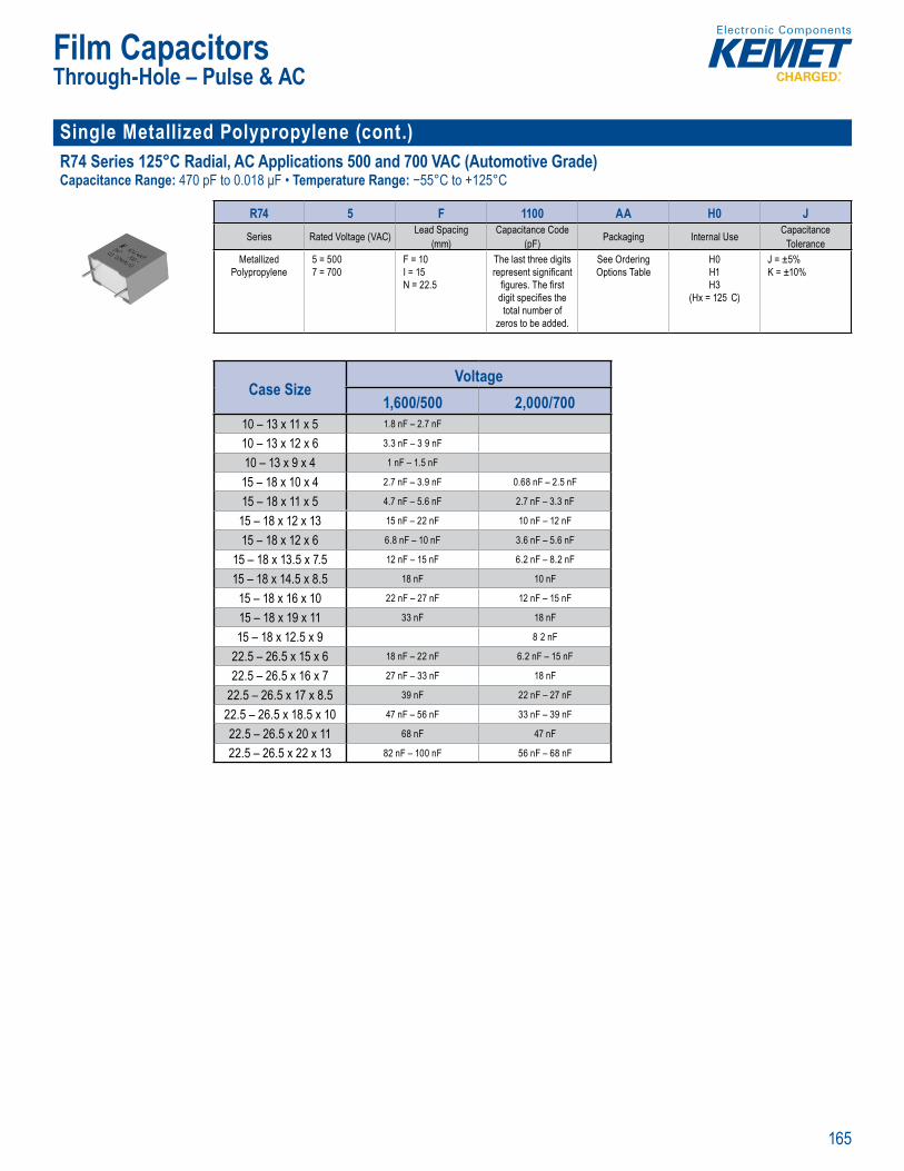
165
Film Capacitors
Single Metallized Polypropylene (cont.) R74 Series 125°C Radial, AC Applications 500 and 700 VAC (Automotive Grade)Capacitance Range: 470 pF to 0.018 μF • Temperature Range: −55°C to +125°C
Operating
Pa t Numb System
R74 5 F 1100 AA H0 JSeries Rated Voltage (VAC) Lead Spacing
(mm)Capacitance Code
(pF) Packaging Internal Use CapacitanceTolerance
Metallized Polypropylene
5 = 5007 = 700
F = 10I = 15N = 22.5
The last three digits represent signifi cant
fi gures. The fi rst digit specifi es the total number of
zeros to be added.
See Ordering Options Table
H0H1H3
(Hx = 125 C)
J = ±5% K = ±10%
Case SizeVoltage
1,600/500 2,000/70010 – 13 x 11 x 5 1.8 nF – 2.7 nF
10 – 13 x 12 x 6 3.3 nF – 3 9 nF
10 – 13 x 9 x 4 1 nF – 1.5 nF
15 – 18 x 10 x 4 2.7 nF – 3.9 nF 0.68 nF – 2.5 nF
15 – 18 x 11 x 5 4.7 nF – 5.6 nF 2.7 nF – 3.3 nF
15 – 18 x 12 x 13 15 nF – 22 nF 10 nF – 12 nF
15 – 18 x 12 x 6 6.8 nF – 10 nF 3.6 nF – 5.6 nF
15 – 18 x 13.5 x 7.5 12 nF – 15 nF 6.2 nF – 8.2 nF
15 – 18 x 14.5 x 8.5 18 nF 10 nF
15 – 18 x 16 x 10 22 nF – 27 nF 12 nF – 15 nF
15 – 18 x 19 x 11 33 nF 18 nF
15 – 18 x 12.5 x 9 8 2 nF
22.5 – 26.5 x 15 x 6 18 nF – 22 nF 6.2 nF – 15 nF
22.5 – 26.5 x 16 x 7 27 nF – 33 nF 18 nF
22.5 – 26.5 x 17 x 8.5 39 nF 22 nF – 27 nF
22.5 – 26.5 x 18.5 x 10 47 nF – 56 nF 33 nF – 39 nF
22.5 – 26.5 x 20 x 11 68 nF 47 nF
22.5 – 26.5 x 22 x 13 82 nF – 100 nF 56 nF – 68 nF
Through-Hole – Pulse & AC
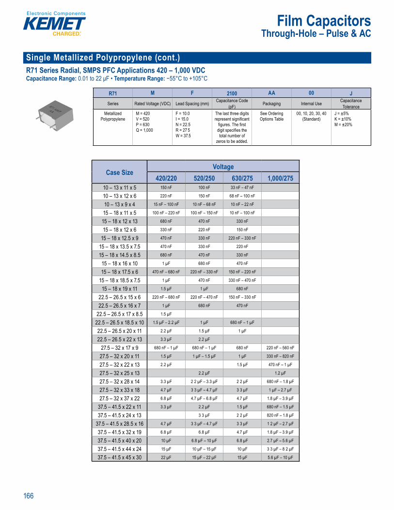
166
Film Capacitors
Single Metallized Polypropylene (cont.) R71 Series Radial, SMPS PFC Applications 420 – 1,000 VDCCapacitance Range: 0.01 to 22 μF • Temperature Range: −55°C to +105°C
Part N mber System
R71 M F 2100 AA 00 JSeries Rated Voltage (VDC) Lead Spacing (mm) Capacitance Code
(pF) Packaging Internal Use CapacitanceTolerance
Metallized Polypropylene
M = 420V = 520P = 630Q = 1,000
F = 10.0I = 15.0N = 22.5R = 27 5W = 37.5
The last three digits represent signifi cant
fi gures. The fi rst digit specifi es the total number of
zeros to be added.
See Ordering Options Table
00, 10, 20, 30, 40 (Standard)
J = ±5% K = ±10% M = ±20%
Case SizeVoltage
420/220 520/250 630/275 1,000/27510 – 13 x 11 x 5 150 nF 100 nF 33 nF – 47 nF
10 – 13 x 12 x 6 220 nF 150 nF 68 nF – 100 nF
10 – 13 x 9 x 4 15 nF – 100 nF 10 nF – 68 nF 10 nF – 22 nF
15 – 18 x 11 x 5 100 nF – 220 nF 100 nF – 150 nF 10 nF – 100 nF
15 – 18 x 12 x 13 680 nF 470 nF 330 nF
15 – 18 x 12 x 6 330 nF 220 nF 150 nF
15 – 18 x 12.5 x 9 470 nF 330 nF 220 nF – 330 nF
15 – 18 x 13.5 x 7.5 470 nF 330 nF 220 nF
15 – 18 x 14.5 x 8.5 680 nF 470 nF 330 nF
15 – 18 x 16 x 10 1 µF 680 nF 470 nF
15 – 18 x 17.5 x 6 470 nF – 680 nF 220 nF – 330 nF 150 nF – 220 nF
15 – 18 x 18.5 x 7.5 1 µF 470 nF 330 nF – 470 nF
15 – 18 x 19 x 11 1.5 µF 1 µF 680 nF
22.5 – 26.5 x 15 x 6 220 nF – 680 nF 220 nF – 470 nF 150 nF – 330 nF
22.5 – 26.5 x 16 x 7 1 µF 680 nF 470 nF
22.5 – 26.5 x 17 x 8.5 1.5 µF
22.5 – 26.5 x 18.5 x 10 1.5 µF – 2.2 µF 1 µF 680 nF – 1 µF
22.5 – 26.5 x 20 x 11 2.2 µF 1.5 µF 1 µF
22.5 – 26.5 x 22 x 13 3.3 µF 2.2 µF
27.5 – 32 x 17 x 9 680 nF – 1 µF 680 nF – 1 µF 680 nF 220 nF – 560 nF
27.5 – 32 x 20 x 11 1.5 µF 1 µF – 1.5 µF 1 µF 330 nF – 820 nF
27.5 – 32 x 22 x 13 2.2 µF 1.5 µF 470 nF – 1 µF
27.5 – 32 x 25 x 13 2.2 µF 1.2 µF
27.5 – 32 x 28 x 14 3.3 µF 2 2 µF – 3.3 µF 2 2 µF 680 nF – 1.8 µF
27.5 – 32 x 33 x 18 4.7 µF 3 3 µF – 4.7 µF 3 3 µF 1 µF – 2.7 µF
27.5 – 32 x 37 x 22 6.8 µF 4.7 µF – 6.8 µF 4.7 µF 1.8 µF – 3.9 µF
37.5 – 41.5 x 22 x 11 3.3 µF 2.2 µF 1.5 µF 680 nF – 1.5 µF
37.5 – 41.5 x 24 x 13 3 3 µF 2 2 µF 820 nF – 1.8 µF
37.5 – 41.5 x 28.5 x 16 4.7 µF 3 3 µF – 4.7 µF 3 3 µF 1 2 µF – 2.7 µF
37.5 – 41.5 x 32 x 19 6.8 µF 6.8 µF 4.7 µF 1.8 µF – 3.9 µF
37.5 – 41.5 x 40 x 20 10 µF 6.8 µF – 10 µF 6.8 µF 2.7 µF – 5.6 µF
37.5 – 41.5 x 44 x 24 15 µF 10 µF – 15 µF 10 µF 3 3 µF – 8 2 µF
37.5 – 41.5 x 45 x 30 22 µF 15 µF – 22 µF 15 µF 5.6 µF – 10 µF
Through-Hole – Pulse & AC
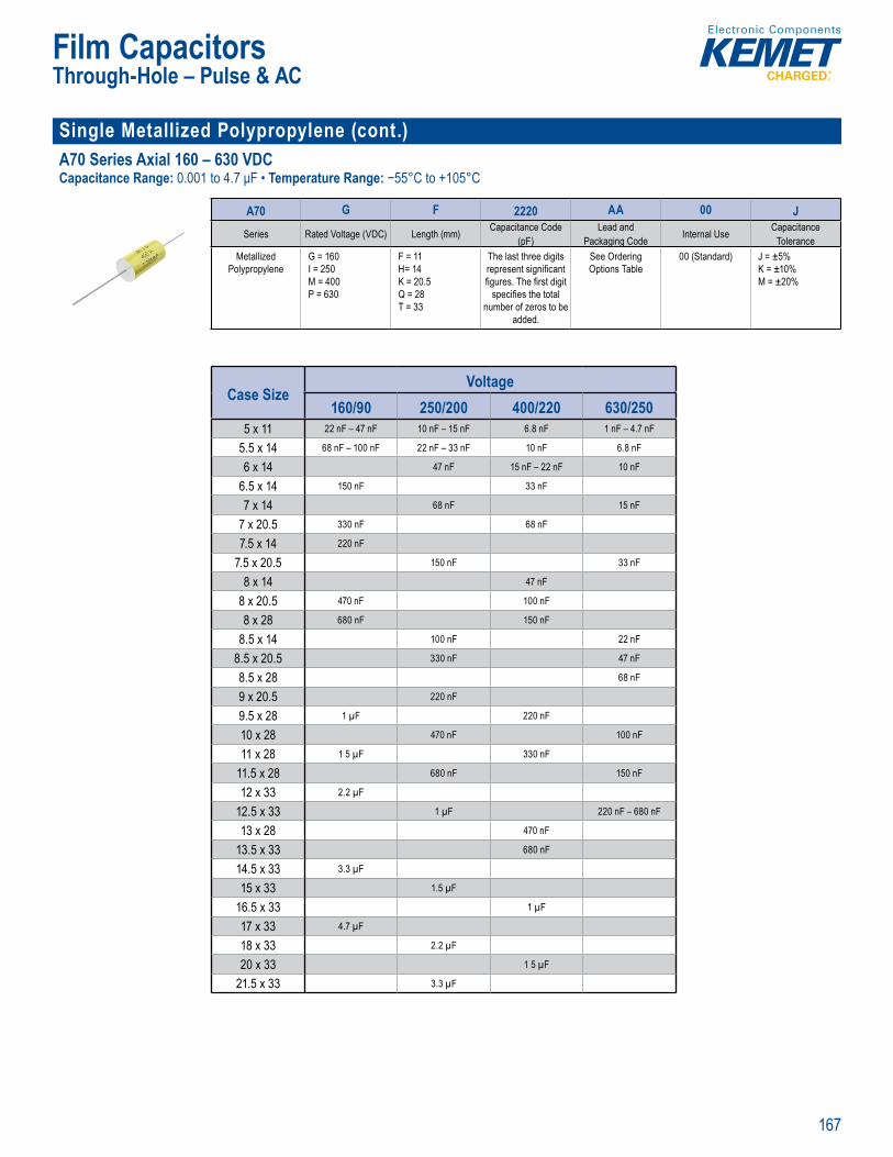
167
Film Capacitors
Single Metallized Polypropylene (cont.) A70 Series Axial 160 – 630 VDCCapacitance Range: 0.001 to 4.7 μF • Temperature Range: −55°C to +105°C
• ape and el h ali
Part u ber System
A70 G F 2220 AA 00 JSeries Rated Voltage (VDC) Length (mm) Capacitance Code
(pF)Lead and
Packaging Code Internal Use CapacitanceTolerance
Metallized Polypropylene
G = 160I = 250M = 400P = 630
F = 11H= 14K = 20.5Q = 28T = 33
The last three digits represent signifi cant fi gures. The fi rst digit
specifi es the total number of zeros to be
added.
See Ordering Options Table
00 (Standard) J = ±5% K = ±10% M = ±20%
Case SizeVoltage
160/90 250/200 400/220 630/2505 x 11 22 nF – 47 nF 10 nF – 15 nF 6.8 nF 1 nF – 4.7 nF
5.5 x 14 68 nF – 100 nF 22 nF – 33 nF 10 nF 6.8 nF
6 x 14 47 nF 15 nF – 22 nF 10 nF
6.5 x 14 150 nF 33 nF
7 x 14 68 nF 15 nF
7 x 20.5 330 nF 68 nF
7.5 x 14 220 nF
7.5 x 20.5 150 nF 33 nF
8 x 14 47 nF
8 x 20.5 470 nF 100 nF
8 x 28 680 nF 150 nF
8.5 x 14 100 nF 22 nF
8.5 x 20.5 330 nF 47 nF
8.5 x 28 68 nF
9 x 20.5 220 nF
9.5 x 28 1 µF 220 nF
10 x 28 470 nF 100 nF
11 x 28 1 5 µF 330 nF
11.5 x 28 680 nF 150 nF
12 x 33 2.2 µF
12.5 x 33 1 µF 220 nF – 680 nF
13 x 28 470 nF
13.5 x 33 680 nF
14.5 x 33 3.3 µF
15 x 33 1.5 µF
16.5 x 33 1 µF
17 x 33 4.7 µF
18 x 33 2.2 µF
20 x 33 1 5 µF
21.5 x 33 3.3 µF
Through-Hole – Pulse & AC
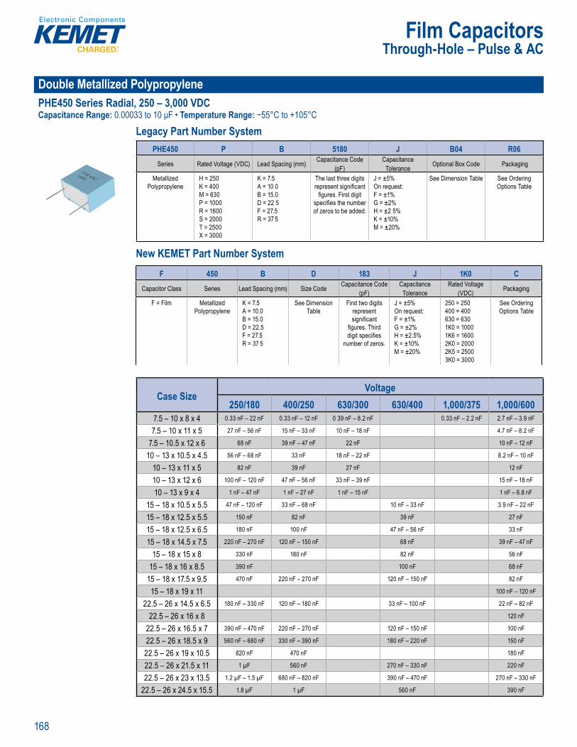
168
Film Capacitors
Double Metallized PolypropylenePHE450 Series Radial, 250 – 3,000 VDCCapacitance Range: 0.00033 to 10 μF • Temperature Range: −55°C to +105°C
Legacy Part Number System
Tape and reel packa H Catego y temp rature
L g a Nu e y
PHE450 P B 5180 J B04 R06Series Rated Voltage (VDC) Lead Spacing (mm) Capacitance Code
(pF)Capacitance
Tolerance Optional Box Code Packaging
Metallized Polypropylene
H = 250K = 400M = 630P = 1000R = 1600S = 2000T = 2500X = 3000
K = 7.5A = 10 0B = 15.0D = 22 5F = 27.5R = 37 5
The last three digits represent signifi cant
fi gures. First digit specifi es the number of zeros to be added.
J = ±5%On request:F = ±1% G = ±2% H = ±2 5% K = ±10% M = ±20%
See Dimension Table See Ordering Options Table
New KEMET Part Number System
p i Ca e ry tem er t
Leg c Pa t Numbe System
PHE 5 PSeries ta ci it nce t l Box ckagi
eta lize H = 250
M 63P 10R 1S T 5X 3
K = 7 5
B 1 2 5
F 7 5R 37 5
t thre t
fi ures F st digit s ecifi s the number
zeros t b adde
5%
F ±1 G = %
± 5% 10%
M ±20%
ee Dimension Table e Orderin
New KEME art Number System
F 450 B D 183 J 1K0 CCapacitor Class Series Lead Spacing (mm) Size Code Capacitance Code
(pF)Capacitance
ToleranceRated Voltage
(VDC) Packaging
F = Film Metallized Polypropylene
K = 7.5A = 10.0B = 15.0D = 22.5F = 27.5R = 37 5
See Dimension Table
First two digits represent signifi cant
fi gures. Third digit specifi es
number of zeros.
J = ±5%On request:F = ±1% G = ±2% H = ±2.5% K = ±10% M = ±20%
250 = 250400 = 400630 = 6301K0 = 10001K6 = 16002K0 = 20002K5 = 25003K0 = 3000
See Ordering Options Table
Case SizeVoltage
250/180 400/250 630/300 630/400 1,000/375 1,000/6007.5 – 10 x 8 x 4 0.33 nF – 22 nF 0.33 nF – 12 nF 0 39 nF – 8.2 nF 0.33 nF – 2.2 nF 2.7 nF – 3.9 nF
7.5 – 10 x 11 x 5 27 nF – 56 nF 15 nF – 33 nF 10 nF – 18 nF 4.7 nF – 8.2 nF
7.5 – 10.5 x 12 x 6 68 nF 39 nF – 47 nF 22 nF 10 nF – 12 nF
10 – 13 x 10.5 x 4.5 56 nF – 68 nF 33 nF 18 nF – 22 nF 8.2 nF – 10 nF
10 – 13 x 11 x 5 82 nF 39 nF 27 nF 12 nF
10 – 13 x 12 x 6 100 nF – 120 nF 47 nF – 56 nF 33 nF – 39 nF 15 nF – 18 nF
10 – 13 x 9 x 4 1 nF – 47 nF 1 nF – 27 nF 1 nF – 15 nF 1 nF – 6.8 nF
15 – 18 x 10.5 x 5.5 47 nF – 120 nF 33 nF – 68 nF 10 nF – 33 nF 3.9 nF – 22 nF
15 – 18 x 12.5 x 5.5 150 nF 82 nF 39 nF 27 nF
15 – 18 x 12.5 x 6.5 180 nF 100 nF 47 nF – 56 nF 33 nF
15 – 18 x 14.5 x 7.5 220 nF – 270 nF 120 nF – 150 nF 68 nF 39 nF – 47 nF
15 – 18 x 15 x 8 330 nF 180 nF 82 nF 56 nF
15 – 18 x 16 x 8.5 390 nF 100 nF 68 nF
15 – 18 x 17.5 x 9.5 470 nF 220 nF – 270 nF 120 nF – 150 nF 82 nF
15 – 18 x 19 x 11 100 nF – 120 nF
22.5 – 26 x 14.5 x 6.5 180 nF – 330 nF 120 nF – 180 nF 33 nF – 100 nF 22 nF – 82 nF
22.5 – 26 x 16 x 8 120 nF
22.5 – 26 x 16.5 x 7 390 nF – 470 nF 220 nF – 270 nF 120 nF – 150 nF 100 nF
22.5 – 26 x 18.5 x 9 560 nF – 680 nF 330 nF – 390 nF 180 nF – 220 nF 150 nF
22.5 – 26 x 19 x 10.5 820 nF 470 nF 180 nF
22.5 – 26 x 21.5 x 11 1 µF 560 nF 270 nF – 330 nF 220 nF
22.5 – 26 x 23 x 13.5 1.2 µF – 1.5 µF 680 nF – 820 nF 390 nF – 470 nF 270 nF – 330 nF
22.5 – 26 x 24.5 x 15.5 1.8 µF 1 µF 560 nF 390 nF
Through-Hole – Pulse & AC
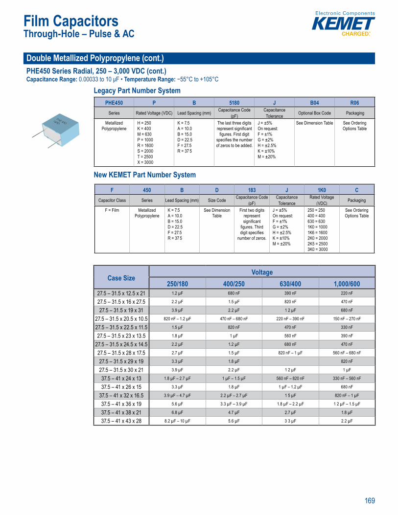
169
Film Capacitors
Double Metallized Polypropylene (cont.)PHE450 Series Radial, 250 – 3,000 VDC (cont.)Capacitance Range: 0.00033 to 10 μF • Temperature Range: −55°C to +105°C
Legacy Part Number System
Rated vo Tape and reel packaging in acc H Catego y temp rature ange of -
L g a Nu e y
PHE450 P B 5180 J B04 R06Series Rated Voltage (VDC) Lead Spacing (mm) Capacitance Code
(pF)Capacitance
Tolerance Optional Box Code Packaging
Metallized Polypropylene
H = 250K = 400M = 630P = 1000R = 1600S = 2000T = 2500X = 3000
K = 7.5A = 10.0B = 15.0D = 22.5F = 27.5R = 37 5
The last three digits represent signifi cant
fi gures. First digit specifi es the number of zeros to be added.
J = ±5%On request:F = ±1% G = ±2% H = ±2.5% K = ±10% M = ±20%
See Dimension Table See Ordering Options Table
New KEMET Part Number System
• Capacitan e d p Ro S Comp iant an lead free te y e e f
Le acy Pa t Number System
Eeries t c citance
(pFcit
To erance l B ck
l i o yp opy e
25
M 6 1
S 20 2
X
K 7 5A B 15.D 22F 2R 3 .
t thre ep e t a
gure . i st d git e t n b
ro
5% que
F ±1 G 2
2 5 K ±1 % M 2
e D i T bl O d n O n b
New KEME Part Number System
F 450 B D 183 J 1K0 CCapacitor Class Series Lead Spacing (mm) Size Code Capacitance Code
(pF)Capacitance
ToleranceRated Voltage
(VDC) Packaging
F = Film Metallized Polypropylene
K = 7.5A = 10.0B = 15.0D = 22.5F = 27.5R = 37 5
See Dimension Table
First two digits represent signifi cant
fi gures. Third digit specifi es
number of zeros.
J = ±5%On request:F = ±1% G = ±2% H = ±2.5% K = ±10% M = ±20%
250 = 250400 = 400630 = 6301K0 = 10001K6 = 16002K0 = 20002K5 = 25003K0 = 3000
See Ordering Options Table
Case SizeVoltage
250/180 400/250 630/400 1,000/60027.5 – 31.5 x 12.5 x 21 1.2 µF 680 nF 390 nF 220 nF
27.5 – 31.5 x 16 x 27.5 2.2 µF 1.5 µF 820 nF 470 nF
27.5 – 31.5 x 19 x 31 3.9 µF 2.2 µF 1 2 µF 680 nF
27.5 – 31.5 x 20.5 x 10.5 820 nF – 1.2 µF 470 nF – 680 nF 220 nF – 390 nF 150 nF – 270 nF
27.5 – 31.5 x 22.5 x 11.5 1.5 µF 820 nF 470 nF 330 nF
27.5 – 31.5 x 23 x 13.5 1.8 µF 1 µF 560 nF 390 nF
27.5 – 31.5 x 24.5 x 14.5 2.2 µF 1.2 µF 680 nF 470 nF
27.5 – 31.5 x 28 x 17.5 2.7 µF 1.5 µF 820 nF – 1 µF 560 nF – 680 nF
27.5 – 31.5 x 29 x 19 3.3 µF 1.8 µF 820 nF
27.5 – 31.5 x 30 x 21 3.9 µF 2.2 µF 1 2 µF 1 µF
37.5 – 41 x 24 x 13 1.8 µF – 2.7 µF 1 µF – 1.5 µF 560 nF – 820 nF 330 nF – 560 nF
37.5 – 41 x 26 x 15 3.3 µF 1.8 µF 1 µF – 1.2 µF 680 nF
37.5 – 41 x 32 x 16.5 3.9 µF – 4.7 µF 2.2 µF – 2.7 µF 1 5 µF 820 nF – 1 µF
37.5 – 41 x 36 x 19 5.6 µF 3.3 µF – 3.9 µF 1.8 µF – 2.2 µF 1 2 µF – 1.5 µF
37.5 – 41 x 38 x 21 6.8 µF 4.7 µF 2.7 µF 1.8 µF
37.5 – 41 x 43 x 28 8.2 µF – 10 µF 5.6 µF 3 3 µF 2.2 µF
Through-Hole – Pulse & AC
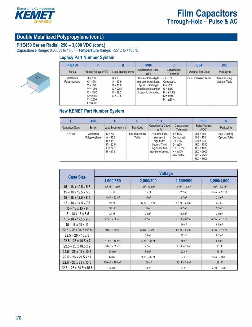
170
Film Capacitors
Double Metallized Polypropylene (cont.)PHE450 Series Radial, 250 – 3,000 VDC (cont.)Capacitance Range: 0.00033 to 10 μF • Temperature Range: −55°C to +105°C
Legacy Part Number System
ape and reel p ckaging in acc H Catego y temp rature ange of -
L g a Nu e y
PHE450 P B 5180 J B04 R06Series Rated Voltage (VDC) Lead Spacing (mm) Capacitance Code
(pF)Capacitance
Tolerance Optional Box Code Packaging
Metallized Polypropylene
H = 250K = 400M = 630P = 1000R = 1600S = 2000T = 2500X = 3000
K = 7.5A = 10.0B = 15.0D = 22.5F = 27.5R = 37 5
The last three digits represent signifi cant
fi gures. First digit specifi es the number of zeros to be added.
J = ±5%On request:F = ±1% G = ±2% H = ±2.5% K = ±10% M = ±20%
See Dimension Table See Ordering Options Table
New KEMET Part Number System
Ro S Comp iant an lead-fre t y e f
Le acy P t Number System
t citance (pF)
citTolerance l
o yprop e
40
M = 6 0P 10
1 = 000
T 25X 30
A 0B = 15.0D 22 5F 27 5R = 3 .5
t thre epresent sign fi cant fi gures. irst d git ec fi es t e numb
of zeros to be dd .
5%n qu
F = ±1% ±2
H ±2. K = ±1 % M ±2
Op i ns T ble
New KEMET Part Number System
F 450 B D 183 J 1K0 CCapacitor Class Series Lead Spacing (mm) Size Code Capacitance Code
(pF)Capacitance
ToleranceRated Voltage
(VDC) Packaging
F = Film Metallized Polypropylene
K = 7.5A = 10.0B = 15.0D = 22.5F = 27.5R = 37 5
See Dimension Table
First two digits represent signifi cant
fi gures. Third digit specifi es
number of zeros.
J = ±5%On request:F = ±1% G = ±2% H = ±2.5% K = ±10% M = ±20%
250 = 250400 = 400630 = 6301K0 = 10001K6 = 16002K0 = 20002K5 = 25003K0 = 3000
See Ordering Options Table
Case SizeVoltage
1,600/650 2,000/700 2,500/900 3,000/1,00015 – 18 x 10.5 x 5.5 2.7 nF – 12 nF 1 nF – 6.8 nF 1 nF – 1.8 nF 1 nF – 1.2 nF
15 – 18 x 12.5 x 5.5 15 nF 8.2 nF 2.2 nF 1.5 nF – 1.8 nF
15 – 18 x 12.5 x 6.5 18 nF – 22 nF 10 nF 2.7 nF 2 2 nF
15 – 18 x 14.5 x 7.5 27 nF 12 nF – 15 nF 3 3 nF – 3 9 nF 2.7 nF
15 – 18 x 15 x 8 33 nF 18 nF 4.7 nF 3 3 nF
15 – 18 x 16 x 8.5 39 nF 22 nF 5.6 nF 3 9 nF
15 – 18 x 17.5 x 9.5 47 nF – 56 nF 27 nF 6.8 nF – 8 2 nF 4.7 nF – 5.6 nF
15 – 18 x 19 x 11 10 nF 6.8 nF
22.5 – 26 x 14.5 x 6.5 10 nF – 39 nF 3 3 nF – 22 nF 4.7 nF – 8.2 nF 4.7 nF – 5.6 nF
22.5 – 26 x 16 x 8 39 nF 12 nF 8 2 nF
22.5 – 26 x 16.5 x 7 47 nF – 56 nF 27 nF – 33 nF 10 nF 6.8 nF
22.5 – 26 x 18.5 x 9 68 nF – 82 nF 47 nF 15 nF – 18 nF 10 nF
22.5 – 26 x 19 x 10.5 100 nF 56 nF 22 nF 12 nF
22.5 – 26 x 21.5 x 11 120 nF 68 nF – 82 nF 27 nF 15 nF – 18 nF
22.5 – 26 x 23 x 13.5 150 nF – 180 nF 100 nF 33 nF – 39 nF 22 nF
22.5 – 26 x 24.5 x 15.5 220 nF 120 nF 47 nF 27 nF – 33 nF
Through-Hole – Pulse & AC
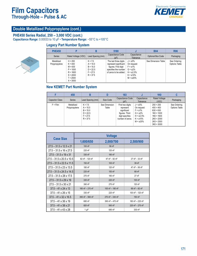
171
Film Capacitors
Double Metallized Polypropylene (cont.)PHE450 Series Radial, 250 – 3,000 VDC (cont.)Capacitance Range: 0.00033 to 10 μF • Temperature Range: −55°C to +105°C
Legacy Part Number System
Rated vo t ape and reel p ckaging in acc H Catego y temp rature ange of -
L g a Nu e y
PHE450 P B 5180 J B04 R06Series Rated Voltage (VDC) Lead Spacing (mm) Capacitance Code
(pF)Capacitance
Tolerance Optional Box Code Packaging
Metallized Polypropylene
H = 250K = 400M = 630P = 1000R = 1600S = 2000T = 2500X = 3000
K = 7.5A = 10.0B = 15.0D = 22.5F = 27.5R = 37 5
The last three digits represent signifi cant
fi gures. First digit specifi es the number of zeros to be added.
J = ±5%On request:F = ±1% G = ±2% H = ±2.5% K = ±10% M = ±20%
See Dimension Table See Ordering Options Table
New KEMET Part Number System
• Capacitan Ro S Comp iant an lead-fre t y e f
Le acy P t Number System
t citance (pF)
citTolerance l
o yprop e
40
M = 6 0P 10
1 = 000
T 25X 30
A 0B = 15.0D 22 5F 27 5R = 3 .5
t thre epresent sign fi cant fi gures. irst d git ec fi es t e numb
of zeros to be dd .
5%n qu
F = ±1% ±2
H ±2. K = ±1 % M ±2
Op i ns T ble
New KEMET Part Number System
F 450 B D 183 J 1K0 CCapacitor Class Series Lead Spacing (mm) Size Code Capacitance Code
(pF)Capacitance
ToleranceRated Voltage
(VDC) Packaging
F = Film Metallized Polypropylene
K = 7.5A = 10.0B = 15.0D = 22.5F = 27.5R = 37 5
See Dimension Table
First two digits represent signifi cant
fi gures. Third digit specifi es
number of zeros.
J = ±5%On request:F = ±1% G = ±2% H = ±2.5% K = ±10% M = ±20%
250 = 250400 = 400630 = 6301K0 = 10001K6 = 16002K0 = 20002K5 = 25003K0 = 3000
See Ordering Options Table
Case SizeVoltage
1,600/650 2,000/700 2,500/90027.5 – 31.5 x 12.5 x 21 100 nF 56 nF
27.5 – 31.5 x 16 x 27.5 220 nF 120 nF
27.5 – 31.5 x 19 x 31 330 nF 180 nF
27.5 – 31.5 x 20.5 x 10.5 82 nF – 120 nF 47 nF – 82 nF 27 nF – 33 nF
27.5 – 31.5 x 22.5 x 11.5 150 nF 100 nF 39 nF
27.5 – 31.5 x 23 x 13.5 180 nF 120 nF 47 nF – 56 nF
27.5 – 31.5 x 24.5 x 14.5 220 nF 150 nF 68 nF
27.5 – 31.5 x 28 x 17.5 270 nF 180 nF 27 nF
27.5 – 31.5 x 29 x 19 330 nF 220 nF 100 nF
27.5 – 31.5 x 30 x 21 390 nF 270 nF 120 nF
37.5 – 41 x 24 x 13 180 nF – 270 nF 100 nF – 180 nF 68 nF – 82 nF
37.5 – 41 x 26 x 15 330 nF 220 nF 100 nF – 120 nF
37.5 – 41 x 32 x 16.5 390 nF – 560 nF 270 nF – 330 nF 150 nF
37.5 – 41 x 36 x 19 680 nF 390 nF – 470 nF 180 nF – 220 nF
37.5 – 41 x 38 x 21 820 nF 560 nF 220 nF – 270 nF
37.5 – 41 x 43 x 28 1 µF 680 nF 330 nF
Through-Hole – Pulse & AC
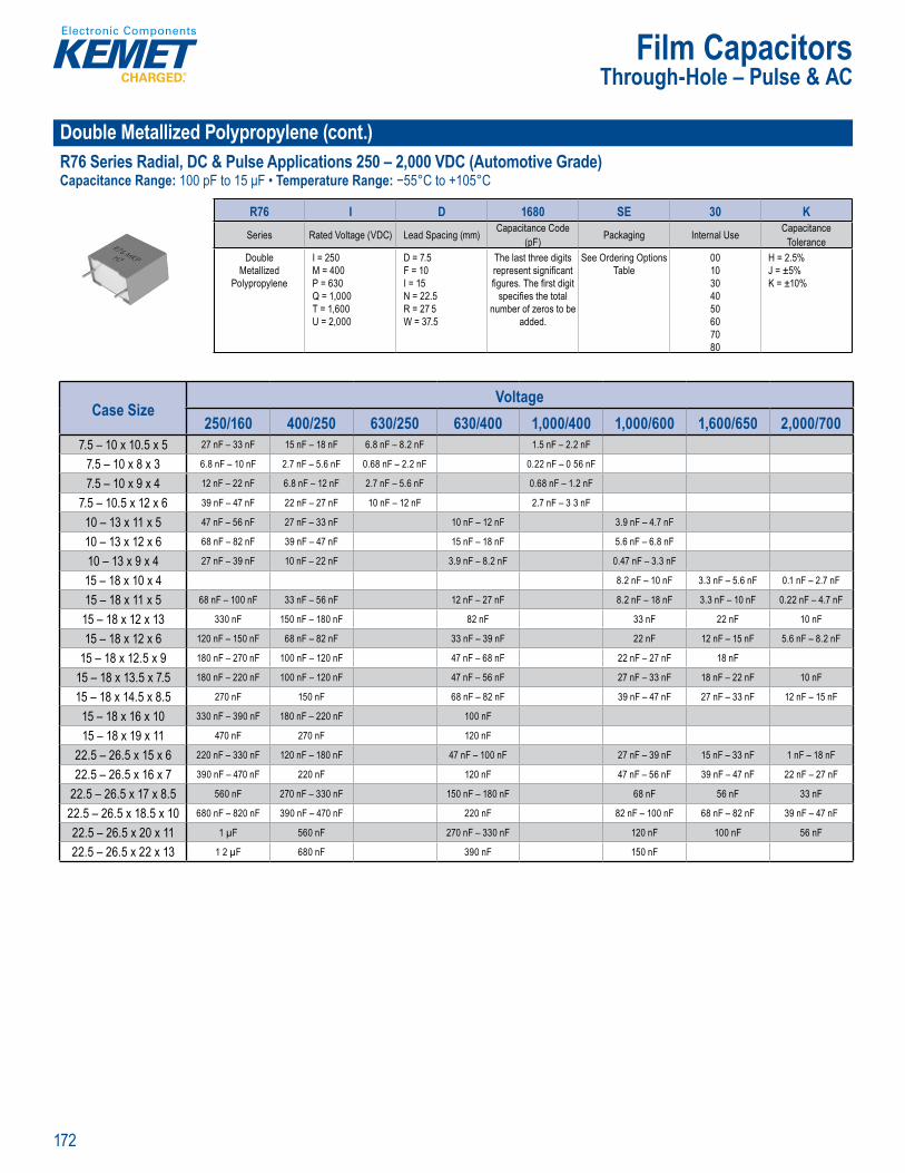
172
Film Capacitors
Double Metallized Polypropylene (cont.)R76 Series Radial, DC & Pulse Applications 250 – 2,000 VDC (Automotive Grade)Capacitance Range: 100 pF to 15 μF • Temperature Range: −55°C to +105°C
22 5mm
Pa t Nu ber System
R76 I D 1680 SE 30 KSeries Rated Voltage (VDC) Lead Spacing (mm) Capacitance Code
(pF) Packaging Internal Use CapacitanceTolerance
DoubleMetallized
Polypropylene
I = 250M = 400P = 630Q = 1,000T = 1,600U = 2,000
D = 7.5F = 10I = 15N = 22.5R = 27 5W = 37.5
The last three digits represent signifi cant fi gures. The fi rst digit
specifi es the total number of zeros to be
added.
See Ordering Options Table
0010304050607080
H = 2.5%J = ±5% K = ±10%
Case SizeVoltage
250/160 400/250 630/250 630/400 1,000/400 1,000/600 1,600/650 2,000/7007.5 – 10 x 10.5 x 5 27 nF – 33 nF 15 nF – 18 nF 6.8 nF – 8.2 nF 1.5 nF – 2.2 nF
7.5 – 10 x 8 x 3 6.8 nF – 10 nF 2.7 nF – 5.6 nF 0.68 nF – 2.2 nF 0.22 nF – 0 56 nF
7.5 – 10 x 9 x 4 12 nF – 22 nF 6.8 nF – 12 nF 2.7 nF – 5.6 nF 0.68 nF – 1.2 nF
7.5 – 10.5 x 12 x 6 39 nF – 47 nF 22 nF – 27 nF 10 nF – 12 nF 2.7 nF – 3 3 nF
10 – 13 x 11 x 5 47 nF – 56 nF 27 nF – 33 nF 10 nF – 12 nF 3.9 nF – 4.7 nF
10 – 13 x 12 x 6 68 nF – 82 nF 39 nF – 47 nF 15 nF – 18 nF 5.6 nF – 6.8 nF
10 – 13 x 9 x 4 27 nF – 39 nF 10 nF – 22 nF 3.9 nF – 8.2 nF 0.47 nF – 3.3 nF
15 – 18 x 10 x 4 8.2 nF – 10 nF 3.3 nF – 5.6 nF 0.1 nF – 2.7 nF
15 – 18 x 11 x 5 68 nF – 100 nF 33 nF – 56 nF 12 nF – 27 nF 8.2 nF – 18 nF 3.3 nF – 10 nF 0.22 nF – 4.7 nF
15 – 18 x 12 x 13 330 nF 150 nF – 180 nF 82 nF 33 nF 22 nF 10 nF
15 – 18 x 12 x 6 120 nF – 150 nF 68 nF – 82 nF 33 nF – 39 nF 22 nF 12 nF – 15 nF 5.6 nF – 8.2 nF
15 – 18 x 12.5 x 9 180 nF – 270 nF 100 nF – 120 nF 47 nF – 68 nF 22 nF – 27 nF 18 nF
15 – 18 x 13.5 x 7.5 180 nF – 220 nF 100 nF – 120 nF 47 nF – 56 nF 27 nF – 33 nF 18 nF – 22 nF 10 nF
15 – 18 x 14.5 x 8.5 270 nF 150 nF 68 nF – 82 nF 39 nF – 47 nF 27 nF – 33 nF 12 nF – 15 nF
15 – 18 x 16 x 10 330 nF – 390 nF 180 nF – 220 nF 100 nF
15 – 18 x 19 x 11 470 nF 270 nF 120 nF
22.5 – 26.5 x 15 x 6 220 nF – 330 nF 120 nF – 180 nF 47 nF – 100 nF 27 nF – 39 nF 15 nF – 33 nF 1 nF – 18 nF
22.5 – 26.5 x 16 x 7 390 nF – 470 nF 220 nF 120 nF 47 nF – 56 nF 39 nF – 47 nF 22 nF – 27 nF
22.5 – 26.5 x 17 x 8.5 560 nF 270 nF – 330 nF 150 nF – 180 nF 68 nF 56 nF 33 nF
22.5 – 26.5 x 18.5 x 10 680 nF – 820 nF 390 nF – 470 nF 220 nF 82 nF – 100 nF 68 nF – 82 nF 39 nF – 47 nF
22.5 – 26.5 x 20 x 11 1 µF 560 nF 270 nF – 330 nF 120 nF 100 nF 56 nF
22.5 – 26.5 x 22 x 13 1 2 µF 680 nF 390 nF 150 nF
Through-Hole – Pulse & AC
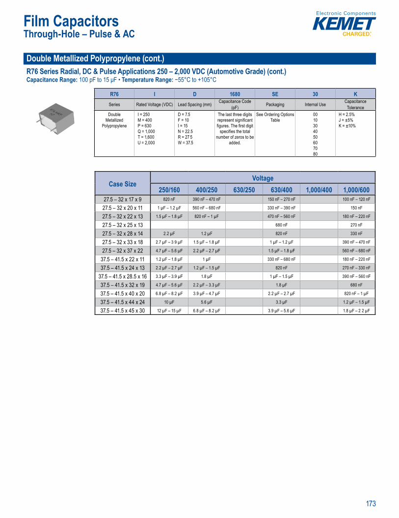
173
Film Capacitors
Double Metallized Polypropylene (cont.)R76 Series Radial, DC & Pulse Applications 250 – 2,000 VDC (Automotive Grade) (cont.)Capacitance Range: 100 pF to 15 μF • Temperature Range: −55°C to +105°C
li atic Opera ing e
22 5mm
Pa t Number System
R76 I D 1680 SE 30 KSeries Rated Voltage (VDC) Lead Spacing (mm) Capacitance Code
(pF) Packaging Internal Use CapacitanceTolerance
DoubleMetallized
Polypropylene
I = 250M = 400P = 630Q = 1,000T = 1,600U = 2,000
D = 7.5F = 10I = 15N = 22.5R = 27 5W = 37.5
The last three digits represent signifi cant fi gures. The fi rst digit
specifi es the total number of zeros to be
added.
See Ordering Options Table
0010304050607080
H = 2.5%J = ±5% K = ±10%
Case SizeVoltage
250/160 400/250 630/250 630/400 1,000/400 1,000/60027.5 – 32 x 17 x 9 820 nF 390 nF – 470 nF 150 nF – 270 nF 100 nF – 120 nF
27.5 – 32 x 20 x 11 1 µF – 1.2 µF 560 nF – 680 nF 330 nF – 390 nF 150 nF
27.5 – 32 x 22 x 13 1.5 µF – 1.8 µF 820 nF – 1 µF 470 nF – 560 nF 180 nF – 220 nF
27.5 – 32 x 25 x 13 680 nF 270 nF
27.5 – 32 x 28 x 14 2.2 µF 1.2 µF 820 nF 330 nF
27.5 – 32 x 33 x 18 2.7 µF – 3 9 µF 1.5 µF – 1.8 µF 1 µF – 1.2 µF 390 nF – 470 nF
27.5 – 32 x 37 x 22 4.7 µF – 5.6 µF 2.2 µF – 2.7 µF 1.5 µF – 1.8 µF 560 nF – 680 nF
37.5 – 41.5 x 22 x 11 1.2 µF – 1.8 µF 1 µF 330 nF – 680 nF 180 nF – 220 nF
37.5 – 41.5 x 24 x 13 2.2 µF – 2.7 µF 1.2 µF – 1.5 µF 820 nF 270 nF – 330 nF
37.5 – 41.5 x 28.5 x 16 3.3 µF – 3.9 µF 1.8 µF 1 µF – 1.5 µF 390 nF – 560 nF
37.5 – 41.5 x 32 x 19 4.7 µF – 5.6 µF 2.2 µF – 3.3 µF 1.8 µF 680 nF
37.5 – 41.5 x 40 x 20 6.8 µF – 8.2 µF 3.9 µF – 4.7 µF 2.2 µF – 2.7 µF 820 nF – 1 µF
37.5 – 41.5 x 44 x 24 10 µF 5.6 µF 3.3 µF 1.2 µF – 1.5 µF
37.5 – 41.5 x 45 x 30 12 µF – 15 µF 6.8 µF – 8.2 µF 3.9 µF – 5.6 µF 1.8 µF – 2 2 µF
Through-Hole – Pulse & AC
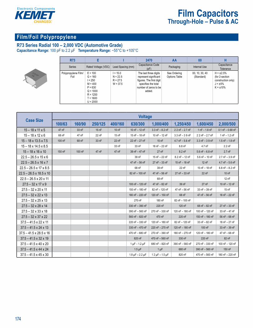
174
Film Capacitors
Film/Foil Polypropylene R73 Series Radial 100 – 2,000 VDC (Automotive Grade)Capacitance Range: 100 pF to 2.2 μF Temperature Range: −55°C to +105°C
• Automo iv
Pa t Num er System
R73 E I 2470 AA 00 HSeries Rated Voltage (VDC) Lead Spacing (mm) Capacitance Code
(pF) Packaging Internal Use CapacitanceTolerance
Polypropylene Film/Foil
E = 100G = 160I = 250M = 400P = 630Q = 1000R = 1250T = 1600U = 2000
I = 15.0N = 22.5R = 27 5W = 37.5
The last three digits represent signifi cant fi gures. The fi rst digit
specifi es the total number of zeros to be
added.
See Ordering Options Table
00, 10, 30, 40 (Standard)
H = ±2.5% (for 2-section construction only)J = ±5% K = ±10%
Case SizeVoltage
100/63 160/90 250/125 400/160 630/300 1,000/400 1,250/450 1,600/450 2,000/50015 – 18 x 11 x 5 47 nF 33 nF 15 nF 10 nF 10 nF – 12 nF 3.3 nF – 8.2 nF 2 2 nF – 2.7 nF 1 nF – 1.8 nF 0.1 nF – 0.68 nF
15 – 18 x 12 x 6 68 nF 47 nF 22 nF 15 nF 15 nF – 18 nF 10 nF – 12 nF 3.3 nF – 3 9 nF 2 2 nF – 2.7 nF 1 nF – 1.2 nF
15 – 18 x 13.5 x 7.5 100 nF 68 nF 33 nF 22 nF 22 nF – 27 nF 15 nF 4.7 nF – 5.6 nF 3.3 nF – 3 9 nF 1.5 nF – 1.8 nF
15 – 18 x 14.5 x 8.5 33 nF 33 nF 18 nF – 22 nF 6.8 nF 4.7 nF 2.2 nF
15 – 18 x 16 x 10 150 nF 100 nF 47 nF 47 nF 39 nF – 47 nF 27 nF 8.2 nF 5.6 nF – 6.8 nF 2.7 nF
22.5 – 26.5 x 15 x 6 39 nF 15 nF – 22 nF 8.2 nF – 12 nF 5.6 nF – 10 nF 2.7 nF – 3.9 nF
22.5 – 26.5 x 16 x 7 47 nF – 56 nF 27 nF – 33 nF 15 nF – 18 nF 12 nF 4.7 nF – 5.6 nF
22.5 – 26.5 x 17 x 8.5 68 nF 39 nF 22 nF 15 nF – 18 nF 6.8 nF – 8.2 nF
22.5 – 26.5 x 18.5 x 10 82 nF – 100 nF 47 nF – 56 nF 27 nF – 33 nF 22 nF 10 nF
22.5 – 26.5 x 20 x 11 68 nF 12 nF
27.5 – 32 x 17 x 9 100 nF – 120 nF 47 nF – 82 nF 39 nF 27 nF 10 nF – 12 nF
27.5 – 32 x 20 x 11 150 nF – 180 nF 82 nF – 120 nF 47 nF – 56 nF 33 nF – 39 nF 15 nF
27.5 – 32 x 22 x 13 180 nF – 220 nF 120 nF – 150 nF 68 nF 47 nF – 56 nF 18 nF – 22 nF
27.5 – 32 x 25 x 13 270 nF 180 nF 82 nF – 100 nF
27.5 – 32 x 28 x 14 330 nF – 390 nF 220 nF 120 nF 68 nF – 82 nF 27 nF – 33 nF
27.5 – 32 x 33 x 18 390 nF – 560 nF 270 nF – 330 nF 120 nF – 180 nF 100 nF – 120 nF 33 nF – 47 nF
27.5 – 32 x 37 x 22 560 nF – 820 nF 470 nF 220 nF 150 nF – 180 nF 56 nF – 68 nF
37.5 – 41.5 x 22 x 11 220 nF – 330 nF 120 nF – 180 nF 82 nF – 120 nF 33 nF – 82 nF 18 nF – 27 nF
37.5 – 41.5 x 24 x 13 330 nF – 470 nF 220 nF – 270 nF 120 nF – 180 nF 100 nF 33 nF – 39 nF
37.5 – 41.5 x 28.5 x 16 470 nF – 680 nF 270 nF – 390 nF 180 nF – 270 nF 120 nF – 180 nF 47 nF – 68 nF
37.5 – 41.5 x 32 x 19 820 nF 470 nF – 560 nF 330 nF 220 nF 82 nF
37.5 – 41.5 x 40 x 20 1 µF – 1.2 µF 680 nF – 820 nF 390 nF – 560 nF 270 nF – 330 nF 100 nF – 120 nF
37.5 – 41.5 x 44 x 24 1.5 µF 1 µF 680 nF 390 nF – 560 nF 150 nF
37.5 – 41.5 x 45 x 30 1.8 µF – 2.2 µF 1 2 µF – 1.5 µF 820 nF 470 nF – 560 nF 180 nF – 220 nF
Through-Hole – Pulse & AC
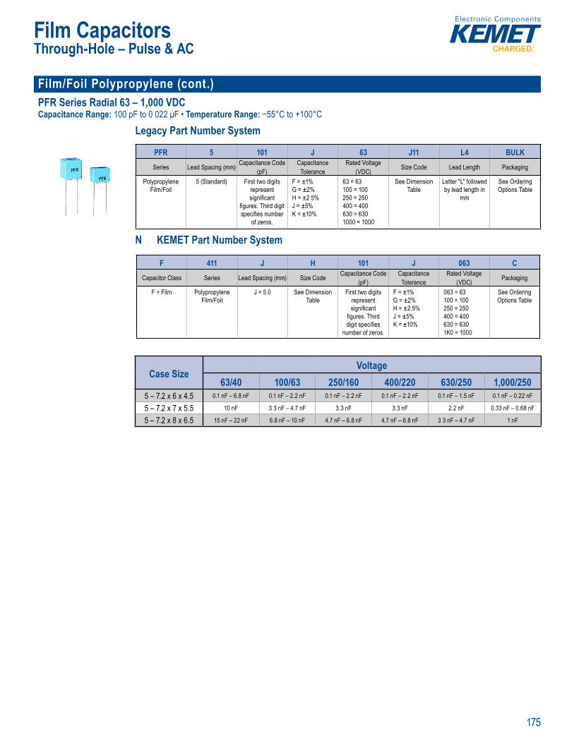
175
Film Capacitors
Film/Foil Polypropylene (cont.)PFR Series Radial 63 – 1,000 VDCCapacitance Range: 100 pF to 0 022 μF • Temperature Range: −55°C to +100°C
Legacy Part Number System
p ead pa
• C tegory t mperature a
Legacy Part Number System
PFR 5 101 J 63 J11 L4 BULKSeries Lead Spacing (mm) Capacitance Code
(pF)Capacitance
ToleranceRated Voltage
(VDC) Size Code Lead Length Packaging
Polypropylene Film/Foil
5 (Standard) First two digits represent signifi cant
fi gures. Third digit specifi es number
of zeros.
F = ±1% G = ±2% H = ±2 5% J = ±5%K = ±10%
63 = 63100 = 100250 = 250400 = 400630 = 6301000 = 1000
See Dimension Table
Letter "L" followed by lead length in
mm
See Ordering Options Table
N KEMET Part Number System
• C pa itan
e acy P t N mber Sy tem
Se ie a tanc (p )
ca
d Vo ) e Co Le ackagin
ypropy 5 (Standard) t o
si nifi ant s Third
ifi of ero
±
H ±2 5 J ± %
25 24 463 631
e Dimensi ter "L" follow
m
ee Orderin
New KEME Part Number System
F 411 J H 101 J 063 CCapacitor Class Series Lead Spacing (mm) Size Code Capacitance Code
(pF)Capacitance
ToleranceRated Voltage
(VDC) Packaging
F = Film Polypropylene Film/Foil
J = 5.0 See Dimension Table
First two digits represent signifi cant
fi gures. Third digit specifi es
number of zeros.
F = ±1% G = ±2% H = ±2.5% J = ±5%K = ±10%
063 = 63100 = 100250 = 250400 = 400630 = 6301K0 = 1000
See Ordering Options Table
Case SizeVoltage
63/40 100/63 250/160 400/220 630/250 1,000/2505 – 7.2 x 6 x 4.5 0.1 nF – 6.8 nF 0.1 nF – 2.2 nF 0.1 nF – 2.2 nF 0.1 nF – 2.2 nF 0.1 nF – 1.5 nF 0.1 nF – 0.22 nF
5 – 7.2 x 7 x 5.5 10 nF 3 3 nF – 4.7 nF 3.3 nF 3.3 nF 2.2 nF 0.33 nF – 0.68 nF
5 – 7.2 x 8 x 6.5 15 nF – 22 nF 6.8 nF – 10 nF 4.7 nF – 6.8 nF 4.7 nF – 6.8 nF 3 3 nF – 4.7 nF 1 nF
Through-Hole – Pulse & AC
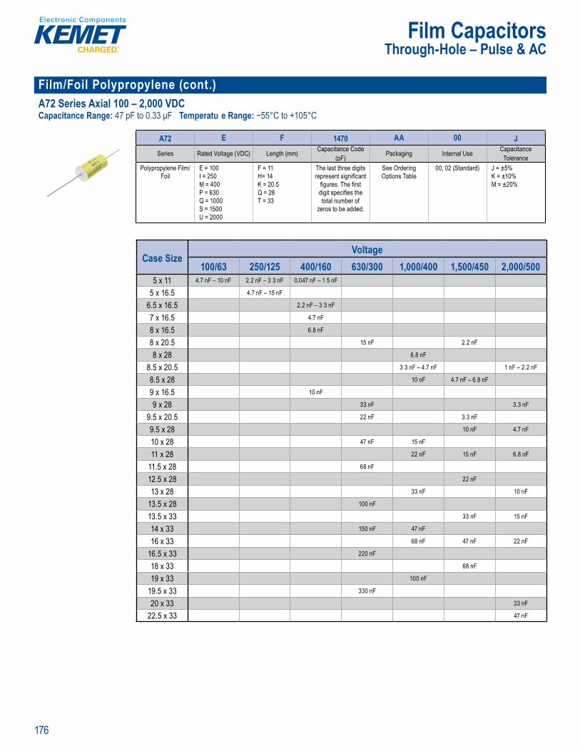
176
Film Capacitors
Film/Foil Polypropylene (cont.)A72 Series Axial 100 – 2,000 VDCCapacitance Range: 47 pF to 0.33 μF Temperatu e Range: −55°C to +105°C
Part Number System
A72 E F 1470 AA 00 JSeries Rated Voltage (VDC) Length (mm) Capacitance Code
(pF) Packaging Internal Use CapacitanceTolerance
Polypropylene Film/Foil
E = 100I = 250M = 400P = 630Q = 1000S = 1500U = 2000
F = 11H= 14K = 20.5Q = 28T = 33
The last three digits represent signifi cant
fi gures. The fi rst digit specifi es the total number of
zeros to be added.
See Ordering Options Table
00, 02 (Standard) J = ±5% K = ±10% M = ±20%
Case SizeVoltage
100/63 250/125 400/160 630/300 1,000/400 1,500/450 2,000/5005 x 11 4.7 nF – 10 nF 2.2 nF – 3 3 nF 0.047 nF – 1 5 nF
5 x 16.5 4.7 nF – 15 nF
6.5 x 16.5 2.2 nF – 3 3 nF
7 x 16.5 4.7 nF
8 x 16.5 6.8 nF
8 x 20.5 15 nF 2.2 nF
8 x 28 6.8 nF
8.5 x 20.5 3 3 nF – 4.7 nF 1 nF – 2.2 nF
8.5 x 28 10 nF 4.7 nF – 6.8 nF
9 x 16.5 10 nF
9 x 28 33 nF 3.3 nF
9.5 x 20.5 22 nF 3.3 nF
9.5 x 28 10 nF 4.7 nF
10 x 28 47 nF 15 nF
11 x 28 22 nF 15 nF 6.8 nF
11.5 x 28 68 nF
12.5 x 28 22 nF
13 x 28 33 nF 10 nF
13.5 x 28 100 nF
13.5 x 33 33 nF 15 nF
14 x 33 150 nF 47 nF
16 x 33 68 nF 47 nF 22 nF
16.5 x 33 220 nF
18 x 33 68 nF
19 x 33 100 nF
19.5 x 33 330 nF
20 x 33 33 nF
22.5 x 33 47 nF
Through-Hole – Pulse & AC
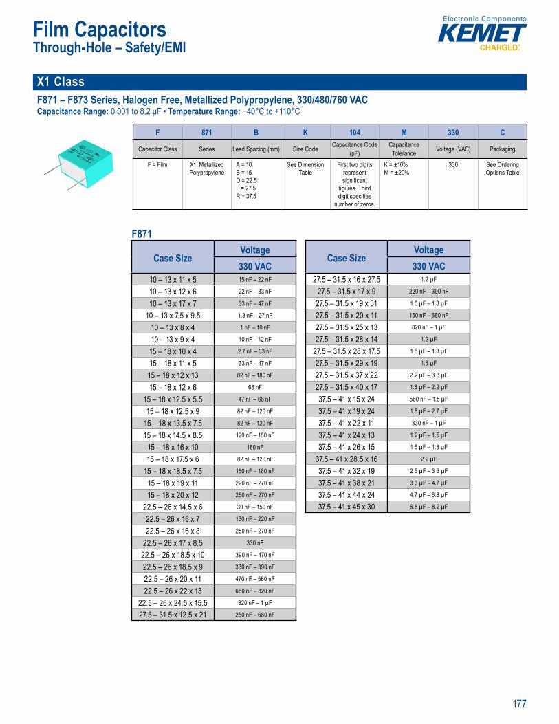
177
Film Capacitors
X1 Class F871 – F873 Series, Halogen Free, Metallized Polypropylene, 330/480/760 VACCapacitance Range: 0.001 to 8.2 μF • Temperature Range: −40°C to +110°C
Part Nu ber System
F 871 B K 104 M 330 C
Capacitor Class Series Lead Spacing (mm) Size Code Capacitance Code (pF)
CapacitanceTolerance Voltage (VAC) Packaging
F = Film X1, Metallized Polypropylene
A = 10B = 15D = 22.5F = 27 5R = 37.5
See Dimension Table
First two digits represent signifi cant
fi gures. Third digit specifi es
number of zeros.
K = ±10% M = ±20%
330 See Ordering Options Table
F871
Case SizeVoltage330 VAC
10 – 13 x 11 x 5 15 nF – 22 nF
10 – 13 x 12 x 6 22 nF – 33 nF
10 – 13 x 17 x 7 33 nF – 47 nF
10 – 13 x 7.5 x 9.5 1.8 nF – 27 nF
10 – 13 x 8 x 4 1 nF – 10 nF
10 – 13 x 9 x 4 10 nF – 12 nF
15 – 18 x 10 x 4 2.7 nF – 33 nF
15 – 18 x 11 x 5 33 nF – 47 nF
15 – 18 x 12 x 13 82 nF – 180 nF
15 – 18 x 12 x 6 68 nF
15 – 18 x 12.5 x 5.5 47 nF – 68 nF
15 – 18 x 12.5 x 9 82 nF – 120 nF
15 – 18 x 13.5 x 7.5 82 nF – 120 nF
15 – 18 x 14.5 x 8.5 120 nF – 150 nF
15 – 18 x 16 x 10 180 nF
15 – 18 x 17.5 x 6 82 nF – 120 nF
15 – 18 x 18.5 x 7.5 150 nF – 180 nF
15 – 18 x 19 x 11 220 nF – 270 nF
15 – 18 x 20 x 12 250 nF – 270 nF
22.5 – 26 x 14.5 x 6 39 nF – 150 nF
22.5 – 26 x 16 x 7 150 nF – 220 nF
22.5 – 26 x 16 x 8 250 nF – 270 nF
22.5 – 26 x 17 x 8.5 330 nF
22.5 – 26 x 18.5 x 10 390 nF – 470 nF
22.5 – 26 x 18.5 x 9 330 nF – 390 nF
22.5 – 26 x 20 x 11 470 nF – 560 nF
22.5 – 26 x 22 x 13 680 nF – 820 nF
22.5 – 26 x 24.5 x 15.5 820 nF – 1 µF
27.5 – 31.5 x 12.5 x 21 250 nF – 680 nF
Case SizeVoltage330 VAC
27.5 – 31.5 x 16 x 27.5 1.2 µF
27.5 – 31.5 x 17 x 9 220 nF – 390 nF
27.5 – 31.5 x 19 x 31 1 5 µF – 1.8 µF
27.5 – 31.5 x 20 x 11 150 nF – 680 nF
27.5 – 31.5 x 25 x 13 820 nF – 1 µF
27.5 – 31.5 x 28 x 14 1.2 µF
27.5 – 31.5 x 28 x 17.5 1 5 µF – 1.8 µF
27.5 – 31.5 x 29 x 19 1.8 µF
27.5 – 31.5 x 37 x 22 2 2 µF – 3 3 µF
27.5 – 31.5 x 40 x 17 1.8 µF – 2.2 µF
37.5 – 41 x 15 x 24 560 nF – 1.5 µF
37.5 – 41 x 19 x 24 1.8 µF – 2.7 µF
37.5 – 41 x 22 x 11 330 nF – 1 µF
37.5 – 41 x 24 x 13 1 2 µF – 1.5 µF
37.5 – 41 x 26 x 15 1 5 µF – 1.8 µF
37.5 – 41 x 28.5 x 16 2 2 µF
37.5 – 41 x 32 x 19 2 5 µF – 3 3 µF
37.5 – 41 x 38 x 21 3 3 µF – 4.7 µF
37.5 – 41 x 44 x 24 4.7 µF – 6.8 µF
37.5 – 41 x 45 x 30 6.8 µF – 8.2 µF
Through-Hole – Safety/EMI
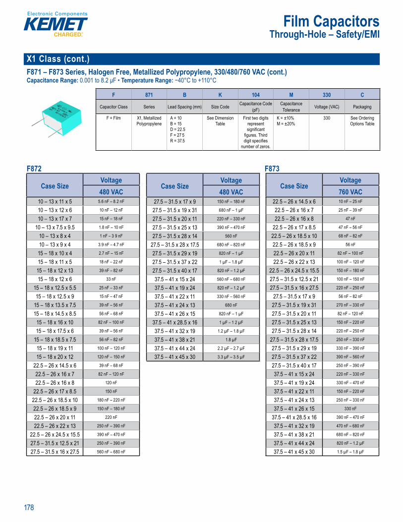
178
Film Capacitors
X1 Class (cont.) F871 – F873 Series, Halogen Free, Metallized Polypropylene, 330/480/760 VAC (cont.)Capacitance Range: 0.001 to 8.2 μF • Temperature Range: −40°C to +110°C
Part umber Syst m
F 871 B K 104 M 330 C
Capacitor Class Series Lead Spacing (mm) Size Code Capacitance Code (pF)
CapacitanceTolerance Voltage (VAC) Packaging
F = Film X1, Metallized Polypropylene
A = 10B = 15D = 22.5F = 27 5R = 37.5
See Dimension Table
First two digits represent signifi cant
fi gures. Third digit specifi es
number of zeros.
K = ±10% M = ±20%
330 See Ordering Options Table
F872 F873
Case SizeVoltage480 VAC
10 – 13 x 11 x 5 5.6 nF – 8.2 nF
10 – 13 x 12 x 6 10 nF – 12 nF
10 – 13 x 17 x 7 15 nF – 18 nF
10 – 13 x 7.5 x 9.5 1.8 nF – 10 nF
10 – 13 x 8 x 4 1 nF – 3 9 nF
10 – 13 x 9 x 4 3.9 nF – 4.7 nF
15 – 18 x 10 x 4 2.7 nF – 15 nF
15 – 18 x 11 x 5 18 nF – 22 nF
15 – 18 x 12 x 13 39 nF – 82 nF
15 – 18 x 12 x 6 33 nF
15 – 18 x 12.5 x 5.5 25 nF – 33 nF
15 – 18 x 12.5 x 9 15 nF – 47 nF
15 – 18 x 13.5 x 7.5 39 nF – 56 nF
15 – 18 x 14.5 x 8.5 56 nF – 68 nF
15 – 18 x 16 x 10 82 nF – 100 nF
15 – 18 x 17.5 x 6 39 nF – 56 nF
15 – 18 x 18.5 x 7.5 56 nF – 82 nF
15 – 18 x 19 x 11 100 nF – 120 nF
15 – 18 x 20 x 12 120 nF – 150 nF
22.5 – 26 x 14.5 x 6 39 nF – 68 nF
22.5 – 26 x 16 x 7 82 nF – 120 nF
22.5 – 26 x 16 x 8 120 nF
22.5 – 26 x 17 x 8.5 150 nF
22.5 – 26 x 18.5 x 10 180 nF – 220 nF
22.5 – 26 x 18.5 x 9 150 nF – 180 nF
22.5 – 26 x 20 x 11 220 nF
22.5 – 26 x 22 x 13 250 nF – 390 nF
22.5 – 26 x 24.5 x 15.5 390 nF – 470 nF
27.5 – 31.5 x 12.5 x 21 250 nF – 390 nF
27.5 – 31.5 x 16 x 27.5 560 nF – 680 nF
Case SizeVoltage480 VAC
27.5 – 31.5 x 17 x 9 150 nF – 180 nF
27.5 – 31.5 x 19 x 31 680 nF – 1 µF
27.5 – 31.5 x 20 x 11 220 nF – 330 nF
27.5 – 31.5 x 25 x 13 390 nF – 470 nF
27.5 – 31.5 x 28 x 14 560 nF
27.5 – 31.5 x 28 x 17.5 680 nF – 820 nF
27.5 – 31.5 x 29 x 19 820 nF – 1 µF
27.5 – 31.5 x 37 x 22 1 µF – 1.8 µF
27.5 – 31.5 x 40 x 17 820 nF – 1.2 µF
37.5 – 41 x 15 x 24 560 nF – 680 nF
37.5 – 41 x 19 x 24 820 nF – 1.2 µF
37.5 – 41 x 22 x 11 330 nF – 560 nF
37.5 – 41 x 24 x 13 680 nF
37.5 – 41 x 26 x 15 820 nF – 1 µF
37.5 – 41 x 28.5 x 16 1 µF – 1 2 µF
37.5 – 41 x 32 x 19 1.2 µF – 1.8 µF
37.5 – 41 x 38 x 21 1.8 µF
37.5 – 41 x 44 x 24 2.2 µF – 2.7 µF
37.5 – 41 x 45 x 30 3.3 µF – 3.5 µF
Case SizeVoltage760 VAC
22.5 – 26 x 14.5 x 6 10 nF – 25 nF
22.5 – 26 x 16 x 7 25 nF – 39 nF
22.5 – 26 x 16 x 8 47 nF
22.5 – 26 x 17 x 8.5 47 nF – 56 nF
22.5 – 26 x 18.5 x 10 68 nF – 82 nF
22.5 – 26 x 18.5 x 9 56 nF
22.5 – 26 x 20 x 11 82 nF – 100 nF
22.5 – 26 x 22 x 13 100 nF – 120 nF
22.5 – 26 x 24.5 x 15.5 150 nF – 180 nF
27.5 – 31.5 x 12.5 x 21 100 nF – 150 nF
27.5 – 31.5 x 16 x 27.5 220 nF – 250 nF
27.5 – 31.5 x 17 x 9 56 nF – 82 nF
27.5 – 31.5 x 19 x 31 270 nF – 330 nF
27.5 – 31.5 x 20 x 11 82 nF – 120 nF
27.5 – 31.5 x 25 x 13 150 nF – 220 nF
27.5 – 31.5 x 28 x 14 220 nF – 250 nF
27.5 – 31.5 x 28 x 17.5 250 nF – 330 nF
27.5 – 31.5 x 29 x 19 330 nF – 390 nF
27.5 – 31.5 x 37 x 22 390 nF – 560 nF
27.5 – 31.5 x 40 x 17 250 nF – 390 nF
37.5 – 41 x 15 x 24 220 nF – 330 nF
37.5 – 41 x 19 x 24 330 nF – 470 nF
37.5 – 41 x 22 x 11 150 nF – 220 nF
37.5 – 41 x 24 x 13 250 nF – 330 nF
37.5 – 41 x 26 x 15 330 nF
37.5 – 41 x 28.5 x 16 390 nF – 470 nF
37.5 – 41 x 32 x 19 470 nF – 680 nF
37.5 – 41 x 38 x 21 680 nF – 820 nF
37.5 – 41 x 44 x 24 820 nF – 1.2 µF
37.5 – 41 x 45 x 30 1.5 µF – 1.8 µF
Through-Hole – Safety/EMI
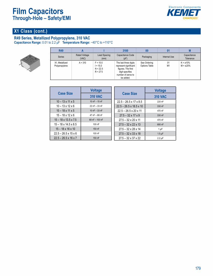
179
Film Capacitors
X1 Class (cont.)R49 Series, Metallized Polypropylene, 310 VACCapacitance Range: 0.01 to 2.2 μF Temperature Range: −40°C to +110°C
• RoHS Co p r in
Par Number Sys em
R49 A I 3100 00 01 M
Series Rated Voltage (VAC)
Lead Spacing (mm)
Capacitance Code (pF) Packaging Internal Use Capacitance
ToleranceX1, Metallized Polypropylene
A = 310 F = 10.0I = 15.0N = 22.5R = 27 5
The last three digits represent signifi cant
fi gures. The fi rst digit specifi es
number of zeros to be added.
See Ordering Options Table
01M1
K = ±10% M = ±20%
Case SizeVoltage310 VAC
10 – 13 x 11 x 5 10 nF – 15 nF
10 – 13 x 12 x 6 22 nF – 33 nF
15 – 18 x 11 x 5 10 nF – 33 nF
15 – 18 x 12 x 6 47 nF – 68 nF
15 – 18 x 13.5 x 7.5 68 nF – 100 nF
15 – 18 x 14.5 x 8.5 100 nF
15 – 18 x 16 x 10 150 nF
22.5 – 26.5 x 15 x 6 100 nF
22.5 – 26.5 x 16 x 7 150 nF
Case SizeVoltage310 VAC
22.5 – 26.5 x 17 x 8.5 220 nF
22.5 – 26.5 x 18.5 x 10 330 nF
22.5 – 26.5 x 20 x 11 470 nF
27.5 – 32 x 17 x 9 330 nF
27.5 – 32 x 20 x 11 470 nF
27.5 – 32 x 22 x 13 680 nF
27.5 – 32 x 28 x 14 1 µF
27.5 – 32 x 33 x 18 1.5 µF
27.5 – 32 x 37 x 22 2.2 µF
Through-Hole – Safety/EMI
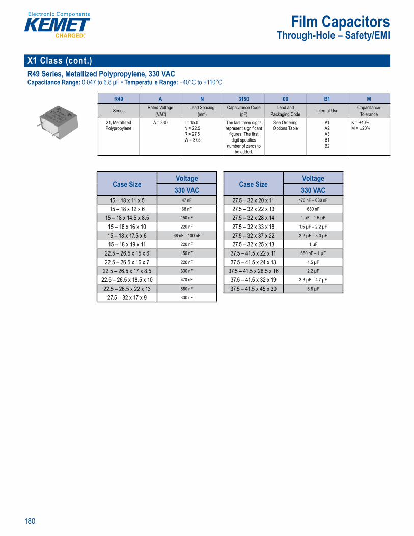
180
Film Capacitors
X1 Class (cont.) R49 Series, Metallized Polypropylene, 330 VACCapacitance Range: 0.047 to 6.8 μF • Temperatu e Range: −40°C to +110°C
Part Nu ber System
R49 A N 3150 00 B1 M
Series Rated Voltage (VAC)
Lead Spacing (mm)
Capacitance Code (pF)
Lead and Packaging Code Internal Use Capacitance
ToleranceX1, Metallized Polypropylene
A = 330 I = 15.0N = 22.5R = 27 5W = 37.5
The last three digits represent signifi cant
fi gures. The fi rst digit specifi es
number of zeros to be added.
See Ordering Options Table
A1A2A3B1B2
K = ±10% M = ±20%
Case SizeVoltage330 VAC
15 – 18 x 11 x 5 47 nF
15 – 18 x 12 x 6 68 nF
15 – 18 x 14.5 x 8.5 150 nF
15 – 18 x 16 x 10 220 nF
15 – 18 x 17.5 x 6 68 nF – 100 nF
15 – 18 x 19 x 11 220 nF
22.5 – 26.5 x 15 x 6 150 nF
22.5 – 26.5 x 16 x 7 220 nF
22.5 – 26.5 x 17 x 8.5 330 nF
22.5 – 26.5 x 18.5 x 10 470 nF
22.5 – 26.5 x 22 x 13 680 nF
27.5 – 32 x 17 x 9 330 nF
Case SizeVoltage330 VAC
27.5 – 32 x 20 x 11 470 nF – 680 nF
27.5 – 32 x 22 x 13 680 nF
27.5 – 32 x 28 x 14 1 µF – 1.5 µF
27.5 – 32 x 33 x 18 1.5 µF – 2.2 µF
27.5 – 32 x 37 x 22 2.2 µF – 3.3 µF
27.5 – 32 x 25 x 13 1 µF
37.5 – 41.5 x 22 x 11 680 nF – 1 µF
37.5 – 41.5 x 24 x 13 1.5 µF
37.5 – 41.5 x 28.5 x 16 2.2 µF
37.5 – 41.5 x 32 x 19 3.3 µF – 4.7 µF
37.5 – 41.5 x 45 x 30 6.8 µF
Through-Hole – Safety/EMI
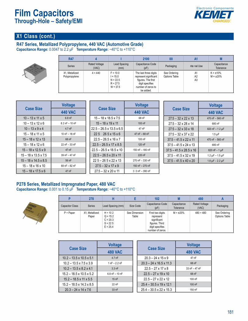
181
Film Capacitors
X1 Class (cont.)R47 Series, Metallized Polypropylene, 440 VAC (Automotive Grade)Capacitance Range: 0.0047 to 2.2 μF Temperature Range: −40°C to +110°C
• RoHS Co p r in
Pa t Num er System
R47 4 I 2100 00 A1 M
Series Rated Voltage (VAC)
Lead Spacing (mm)
Capacitance Code (pF) Packaging nte nal Use Capacitance
ToleranceX1, Metallized Polypropylene
4 = 440 F = 10.0I = 15.0N = 22.5R = 27 5W = 37.5
The last three digits represent signifi cant
fi gures. The fi rst digit specifi es
number of zeros to be added.
See Ordering Options Table
A1A2A3
K = ±10% M = ±20%
Case SizeVoltage440 VAC
10 – 13 x 11 x 5 6.8 nF
10 – 13 x 12 x 6 8.2 nF – 10 nF
10 – 13 x 9 x 4 4.7 nF
15 – 18 x 11 x 5 10 nF – 18 nF
15 – 18 x 12 x 13 68 nF
15 – 18 x 12 x 6 22 nF – 33 nF
15 – 18 x 12.5 x 9 47 nF
15 – 18 x 13.5 x 7.5 39 nF – 47 nF
15 – 18 x 14.5 x 8.5 56 nF
15 – 18 x 16 x 10 68 nF – 82 nF
15 – 18 x 17.5 x 6 47 nF
Case SizeVoltage440 VAC
15 – 18 x 18.5 x 7.5 68 nF
15 – 18 x 19 x 11 100 nF
22.5 – 26.5 x 13.5 x 6.5 47 nF
22 5 26 5 x 15 x 6 47 nF – 68 nF
22.5 – 26.5 x 16 x 7 100 nF
22.5 – 26.5 x 17 x 8.5 120 nF
22.5 – 26.5 x 18.5 x 10 150 nF – 180 nF
22.5 – 26.5 x 20 x 11 220 nF
22 5 – 26 5 x 22 x 13 270 nF – 330 nF
27.5 – 32 x 17 x 9 150 nF – 270 nF
27.5 – 32 x 20 x 11 3 0 nF – 390 nF
Case SizeVoltage440 VAC
27.5 – 32 x 22 x 13 470 nF – 560 nF
27.5 – 32 x 28 x 14 680 nF
27.5 – 32 x 33 x 18 820 nF – 1 2 µF
27.5 – 32 x 37 x 22 1.5 µF
37.5 – 41.5 x 22 x 11 470 nF – 560 nF
37.5 – 41.5 x 24 x 13 680 nF
37.5 – 41.5 x 28.5 x 16 820 nF – 1 µF
37.5 – 41.5 x 32 x 19 1.2 µF – 1.5 µF
37.5 – 41.5 x 40 x 20 1.8 µF – 2.2 µF
P278 Series, Metallized Impregnated Paper, 480 VACCapacitance Range: 0.001 to 0.15 μF Temperature Range: −40°C to +110°C
a e it 0 15 µ Lead spaci p t 2 , H C f ter i t o s Ope a n t nge of -4 ˚C to +110 0% sc es a 2, 00 VDC H ghe t o e a g ac ive d p
mma
j t l r ation ue to m r gnat
diele ric pr gn es e cel ent stab lity ili y
ulated ate i ishin q
y g i suppress 1 and acro applic
Par Num er System
P 278 H E 102 M 480 A
Capacitor Class Series Lead Spacing (mm) Size Code Capacitance Code (pF)
CapacitanceTolerance
Rated Voltage (VAC) Packaging
P = Paper X1, Metallized Paper
H = 10 2Q = 15.2C = 20.3S = 22 5E = 25.4
See Dimension Table
First two digits represent signifi cant
fi gures. Third digit specifi es
number of zeros.
M = ±20% 480 = 480 See Ordering Options Table
Case SizeVoltage480 VAC
10.2 – 13.5 x 10.5 x 5.1 4.7 nF
10.2 – 13.5 x 7.5 x 3.9 1 nF – 2.2 nF
10.2 – 13.5 x 8.2 x 4.1 3.3 nF
15.2 – 18.5 x 10.5 x 5.2 6.8 nF – 10 nF
15.2 – 18.5 x 11 x 5.5 15 nF
15.2 – 18.5 x 14.3 x 8.5 22 nF
20.3 – 24 x 14 x 7.6 33 nF
Case SizeVoltage480 VAC
20.3 – 24 x 15 x 9 47 nF
20.3 – 24 x 16.5 x 11.3 68 nF
22.5 – 27 x 17 x 8 33 nF – 47 nF
22.5 – 27 x 19 x 10 68 nF
22.5 – 27 x 22 x 12 100 nF
25.4 – 30.5 x 19 x 12.1 100 nF
25.4 – 30.5 x 22 x 15.3 150 nF
Through-Hole – Safety/EMI

182
Film Capacitors
X1 Class (cont.) P410 Series, Metallized Impregnated Paper 300 VACCapacitance Range: 0.022 to 0.1 μF • Temperature Range: −40°C to +85°C
Par u ber S stem
P 410 Q M 223 M 300 A H101Capacitor
Class Series Lead Spacing(mm) Size Code Capacitance Code (pF) Capacitance
ToleranceRated Voltage
(VAC) Packaging Resistance (Ω)
P= Metallized
Paper
RC Snubber Q = 15.2C = 20.3E = 25.4
See Dimension
Table
First two digits represent signifi cant fi gures. Third digit specifi es number of
zeros.
M = ±20% 300 = 300 See Ordering Options Table
H plus fi rst two digits represent
signifi cant fi gures. Third digit specifi es number
of zeros.
Case SizeVoltage
1,000/30015.2 – 18.5 x 13 x 7.3 22 nF
15.2 – 18.5 x 14.3 x 8.5 33 nF
20.3 – 24 x 15 x 9 47 nF
20.3 – 24 x 16.5 x 11.3 68 nF
25.4 – 30.5 x 16.1 x 10.6 100 nF
Through-Hole – Safety/EMI

183
Film Capacitors
X1 Class (cont.)PME271E Series, Metallized Impregnated Paper, 300 VACCapacitance Range: 0.01 to 0.22 μF • Temperature Range: −40°C to +110°C
acy Part Number System
Capa itan g
fl ammabi ity
Legacy Part Number System
PME271 E (D) 510(0) M R30
Series Rated Voltage (VAC) Lead Spacing (mm) Capacitance Code (pF) CapacitanceTolerance Packaging
X1, Metallized Paper E = 300 Blank = StandardD = 22.5
The last th ee digits represent signifi cant fi gures. The fi rst digit specifi es the
total number of digits.
M = ±20% (for C ≤ 0.1 µF)K = ±10% (for C > 0.1 µF)
See Ordering Options Table
New KEMET Part Number System
apaci a Clima ic c
fl ma y
L a Nu y
Tolerance
D = 2
sent signifi cant fi gu The fi rst digit specifi es t e
total number of d gits
K = ± 0% (for C 0 F)
Options Table
New KEMET Part Number System
P 277 Q E 103 M 300 ACapacitor
Class Series Lead Spacing (mm) Size Code Capacitance Code (pF) CapacitanceTolerance
Rated Voltage (VAC) Packaging
P = Paper X1, Metallized Paper
Q = 15.2C = 20 3S = 22.5E = 25.4
See Dimension Table
First two digits represent signifi cant fi gures. Third digit
specifi es number of zeros.
M = ±20% (for C ≤ 0.1 µF)K = ±10% (for C > 0.1 µF)
300 = 300 See Ordering Options Table
Case SizeVoltage300 VAC
15.2 – 18.5 x 10.5 x 5.2 10 nF – 15 nF
15.2 – 18.5 x 14.3 x 8.5 47 nF
15.2 – 19 x 13 x 7.3 22 nF – 33 nF
20.3 – 24 x 14 x 7.6 68 nF
20.3 – 24 x 16.5 x 11.3 100 nF
22.5 – 27 x 17 x 8 68 nF – 100 nF
22.5 – 27 x 19 x 10 150 nF
22.5 – 27 x 22 x 12 220 nF
25.4 – 30.5 x 16.1 x 10.6 150 nF
25.4 – 30.5 x 19 x 12.1 220 nF
Through-Hole – Safety/EMI

184
Film Capacitors
X1 Class (cont.)PHE844 Series, Metallized Polypropylene, 440/480 VACCapacitance Range: 0.1 to 2.2 μF • Temperature Range: −40°C to +105°C
Legacy Part Number System
• Sel -healing properties
Legacy Part Number System
PHE844 R D 6100 M R06L2
Series Rated Voltage (VAC) Lead Spacing (mm) Capacitance Code (pF) CapacitanceTolerance Packaging
X1, Metallized Polypropylene
R = 440 D = 22.5F = 27 5R = 37.5
The last three digits represent signifi cant fi gures. The fi rst digit
specifi es the total number of digits.
K = ±10% M = ±20%
See Ordering Options Table
New KEMET Part Number System
Lega P t Numb r Syst m
citToleranc
o propylene
F 27R 37.
T t epresent sign cant gures. The fi rst digit specifi es he total numbe of d gits
% M ±2
Table
New KEMET Part Number System
F 844 D H 104 M 440 CCapacitor
Class Series Lead Spacing (mm) Size Code Capacitance Code (pF) Capacitance
ToleranceRated Voltage
(VAC) Packaging
F = Film X1, Metallized Polypropylene
D = 22.5F = 27.5R = 37 5
See Dimension
Table
First two digits represent signifi cant fi gures. Third digit specifi es number of zeros.
K = ±10% M = ±20%
440 = 440 See Ordering Options Table
Case SizeVoltage480 VAC
22.5 – 26 x 16 x 8 100 nF
22.5 – 26 x 18.5 x 9 150 nF
22.5 – 26 x 21.5 x 11 220 nF
22.5 – 26 x 23 x 13.5 330 nF
22.5 – 26 x 24.5 x 15.5 470 nF
27.5 – 31.5 x 20.5 x 10.5 220 nF
27.5 – 31.5 x 23 x 13.5 330 nF
27.5 – 31.5 x 24.5 x 14.5 470 nF
27.5 – 31.5 x 28 x 17.5 680 nF
27.5 – 31.5 x 30 x 21 1 µF
37.5 – 41 x 24 x 13 470 nF – 680 nF
37.5 – 41 x 26 x 15 1 µF
37.5 – 41 x 36 x 19 1.5 µF
37.5 – 41 x 38 x 21 2.2 µF
Through-Hole – Safety/EMI
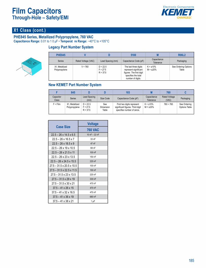
185
Film Capacitors
X1 Class (cont.)PHE845 Series, Metallized Polypropylene, 760 VACCapacitance Range: 0.01 to 1 0 μF • Temperat re Range: −40°C to +105°C
Legacy Part Number System
• Capacitan i
Legacy Part Number System
PHE845 V D 5100 M R06L2
Series Rated Voltage (VAC) Lead Spacing (mm) Capacitance Code (pF) CapacitanceTolerance Packaging
X1, Metallized Polypropylene
V = 760 D = 22.5F = 27 5R = 37.5
The last three digits represent signifi cant fi gures The fi rst digit
specifi es the total number of digits.
K = ±10% M = ±20%
See Ordering Options Table
New KEMET Part Number System
li atic Tape nd
Legacy Part Numbe System
Series ta ac nce C c t ackagin
Metalli V = 760 = 22 5
R 37 5
The last th ee di its
fi ures The fi rst digit specifi es the total number o digi s.
O der ng O
New KEME Part Number System
F 845 D D 103 M 760 CCapacitor
Class Series Lead Spacing (mm) Size Code Capacitance Code (pF) Capacitance
ToleranceRated Voltage
(VAC) Packaging
F = Film X1, Metallized Polypropylene
D = 22.5F = 27.5R = 37.5
See Dimension
Table
First two digits represent signifi cant fi gures. Third digit specifi es number of zeros.
K = ±10% M = ±20%
760 = 760 See Ordering Options Table
Case SizeVoltage760 VAC
22.5 – 26 x 14.5 x 6.5 10 nF – 22 nF
22.5 – 26 x 16.5 x 7 33 nF
22.5 – 26 x 18.5 x 9 47 nF
22.5 – 26 x 19 x 10.5 68 nF
22.5 – 26 x 21.5 x 11 100 nF
22.5 – 26 x 23 x 13.5 150 nF
22.5 – 26 x 24.5 x 15.5 220 nF
27.5 – 31.5 x 20.5 x 10.5 100 nF
27.5 – 31.5 x 22.5 x 11.5 150 nF
27.5 – 31.5 x 23 x 13.5 220 nF
27.5 – 31.5 x 29 x 19 330 nF
27.5 – 31.5 x 30 x 21 470 nF
37.5 – 41 x 26 x 15 470 nF
37.5 – 41 x 32 x 16.5 470 nF
37.5 – 41 x 36 x 19 680 nF
37.5 – 41 x 38 x 21 1 µF
Through-Hole – Safety/EMI
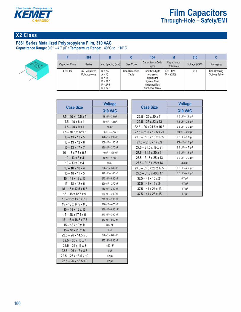
186
Film Capacitors
X2 ClassF861 Series Metallized Polypropylene Film, 310 VACCapacitance Range: 0.01 – 4 7 µF • Temperature Range: −40°C to +110°C
Part N mber System
F 861 B C 104 M 310 C
Capacitor Class Series Lead Spacing (mm) Size Code Capacitance Code (pF)
CapacitanceTolerance Voltage (VAC) Packaging
F = Film X2, Metallized Polypropylene
K = 7 5A = 10B = 15D = 22.5F = 27 5R = 37.5
See Dimension Table
First two digits represent signifi cant
fi gures. Third digit specifi es
number of zeros.
K = ±10% M = ±20%
310 See Ordering Options Table
Case SizeVoltage310 VAC
7.5 – 10 x 10.5 x 5 18 nF – 33 nF
7.5 – 10 x 8 x 4 10 nF – 12 nF
7.5 – 10 x 9 x 4 15 nF
7.5 – 10.5 x 12 x 6 33 nF – 47 nF
10 – 13 x 11 x 5 68 nF – 100 nF
10 – 13 x 12 x 6 100 nF – 150 nF
10 – 13 x 17 x 7 150 nF – 270 nF
10 – 13 x 7.5 x 9.5 10 nF – 120 nF
10 – 13 x 8 x 4 10 nF – 47 nF
10 – 13 x 9 x 4 56 nF
15 – 18 x 10 x 4 10 nF – 120 nF
15 – 18 x 11 x 5 120 nF – 180 nF
15 – 18 x 12 x 13 270 nF – 680 nF
15 – 18 x 12 x 6 220 nF – 270 nF
15 – 18 x 12.5 x 5.5 180 nF – 220 nF
15 – 18 x 12.5 x 9 150 nF – 390 nF
15 – 18 x 13.5 x 7.5 270 nF – 390 nF
15 – 18 x 14.5 x 8.5 390 nF – 470 nF
15 – 18 x 16 x 10 560 nF – 680 nF
15 – 18 x 17.5 x 6 270 nF – 390 nF
15 – 18 x 18.5 x 7.5 470 nF – 560 nF
15 – 18 x 19 x 11 820 nF
15 – 18 x 20 x 12 1 µF
22.5 – 26 x 14.5 x 6 39 nF – 470 nF
22.5 – 26 x 16 x 7 470 nF – 680 nF
22.5 – 26 x 16 x 8 820 nF
22.5 – 26 x 17 x 8.5 1 µF
22.5 – 26 x 18.5 x 10 1.2 µF
22.5 – 26 x 18.5 x 9 1.2 µF
Case SizeVoltage310 VAC
22.5 – 26 x 20 x 11 1 5 µF – 1.8 µF
22.5 – 26 x 22 x 13 1.8 µF – 2.5 µF
22.5 – 26 x 24.5 x 15.5 2 5 µF – 3 3 µF
27.5 – 31.5 x 12.5 x 21 250 nF – 2.2 µF
27.5 – 31.5 x 16 x 27.5 2 5 µF – 3 9 µF
27.5 – 31.5 x 17 x 9 150 nF – 1 2 µF
27.5 – 31.5 x 19 x 31 3 9 µF – 4.7 µF
27.5 – 31.5 x 20 x 11 1 2 µF – 1.8 µF
27.5 – 31.5 x 25 x 13 2 2 µF – 3 3 µF
27.5 – 31.5 x 28 x 14 3 3 µF
27.5 – 31.5 x 28 x 17.5 3 9 µF – 4.7 µF
27.5 – 31.5 x 40 x 17 3 3 µF – 4.7 µF
37.5 – 41 x 15 x 24 4.7 µF
37.5 – 41 x 19 x 24 4.7 µF
37.5 – 41 x 24 x 13 4.7 µF
37.5 – 41 x 26 x 15 4.7 µF
Through-Hole – Safety/EMI
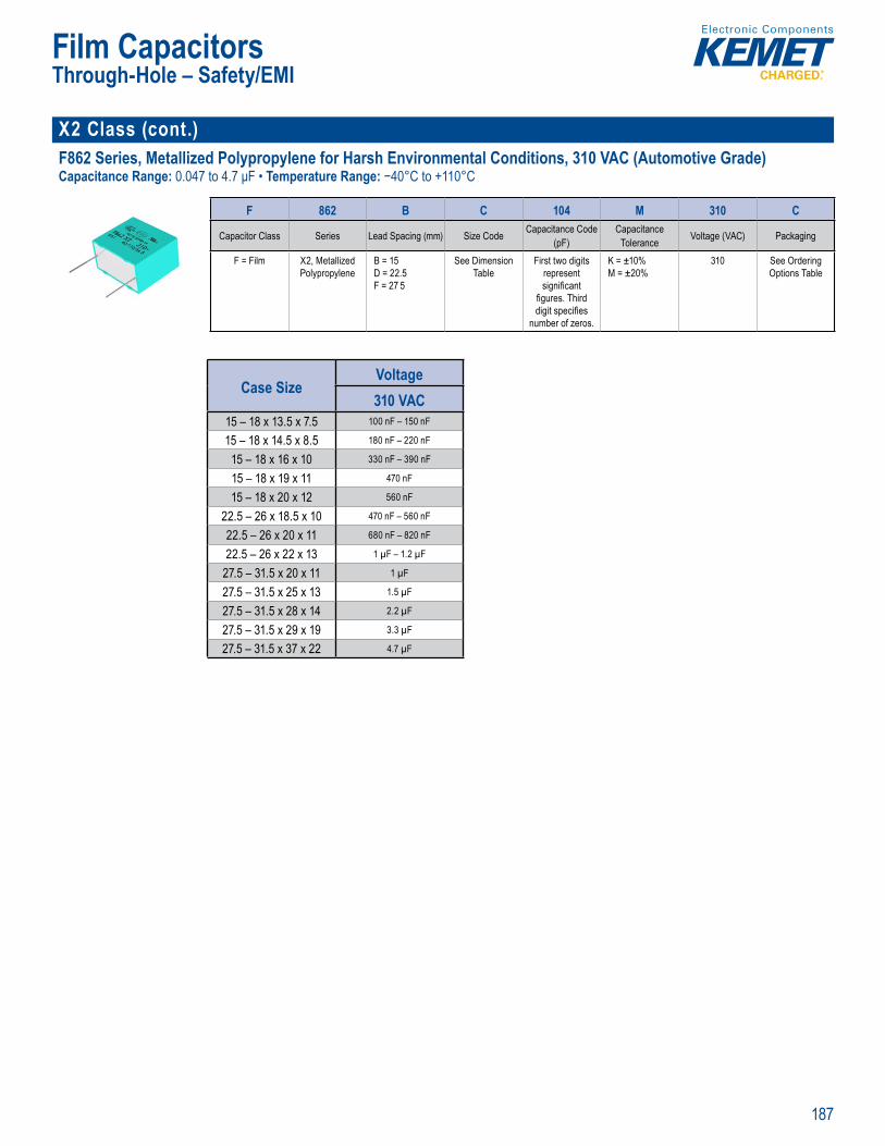
187
Film Capacitors
X2 Class (cont.) F862 Series, Metallized Polypropylene for Harsh Environmental Conditions, 310 VAC (Automotive Grade)Capacitance Range: 0.047 to 4.7 μF • Temperature Range: −40°C to +110°C
• RoHS Co i
Part N ber System
F 862 B C 104 M 310 C
Capacitor Class Series Lead Spacing (mm) Size Code Capacitance Code (pF)
CapacitanceTolerance Voltage (VAC) Packaging
F = Film X2, Metallized Polypropylene
B = 15D = 22.5F = 27 5
See Dimension Table
First two digits represent signifi cant
fi gures. Third digit specifi es
number of zeros.
K = ±10% M = ±20%
310 See Ordering Options Table
Case SizeVoltage310 VAC
15 – 18 x 13.5 x 7.5 100 nF – 150 nF
15 – 18 x 14.5 x 8.5 180 nF – 220 nF
15 – 18 x 16 x 10 330 nF – 390 nF
15 – 18 x 19 x 11 470 nF
15 – 18 x 20 x 12 560 nF
22.5 – 26 x 18.5 x 10 470 nF – 560 nF
22.5 – 26 x 20 x 11 680 nF – 820 nF
22.5 – 26 x 22 x 13 1 µF – 1.2 µF
27.5 – 31.5 x 20 x 11 1 µF
27.5 – 31.5 x 25 x 13 1.5 µF
27.5 – 31.5 x 28 x 14 2.2 µF
27.5 – 31.5 x 29 x 19 3.3 µF
27.5 – 31.5 x 37 x 22 4.7 µF
Through-Hole – Safety/EMI
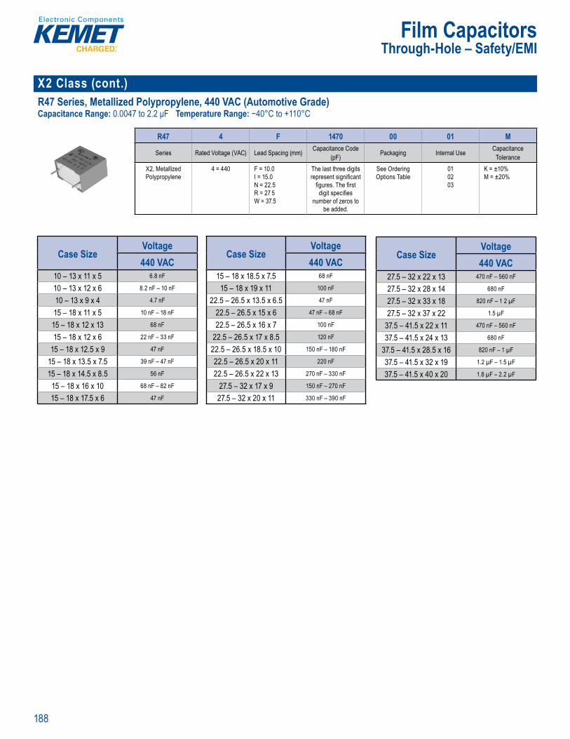
188
Film Capacitors
X2 Class (cont.)R47 Series, Metallized Polypropylene, 440 VAC (Automotive Grade)Capacitance Range: 0.0047 to 2.2 μF Temperature Range: −40°C to +110°C
Pa t Num er System
R47 4 F 1470 00 01 M
Series Rated Voltage (VAC) Lead Spacing (mm) Capacitance Code (pF) Packaging Internal Use Capacitance
ToleranceX2, Metallized Polypropylene
4 = 440 F = 10.0I = 15.0N = 22.5R = 27 5W = 37.5
The last three digits represent signifi cant
fi gures. The fi rst digit specifi es
number of zeros to be added.
See Ordering Options Table
010203
K = ±10% M = ±20%
Case SizeVoltage440 VAC
10 – 13 x 11 x 5 6.8 nF
10 – 13 x 12 x 6 8.2 nF – 10 nF
10 – 13 x 9 x 4 4.7 nF
15 – 18 x 11 x 5 10 nF – 18 nF
15 – 18 x 12 x 13 68 nF
15 – 18 x 12 x 6 22 nF – 33 nF
15 – 18 x 12.5 x 9 47 nF
15 – 18 x 13.5 x 7.5 39 nF – 47 nF
15 – 18 x 14.5 x 8.5 56 nF
15 – 18 x 16 x 10 68 nF – 82 nF
15 – 18 x 17.5 x 6 47 nF
Case SizeVoltage440 VAC
15 – 18 x 18.5 x 7.5 68 nF
15 – 18 x 19 x 11 100 nF
22.5 – 26.5 x 13.5 x 6.5 47 nF
22.5 – 26.5 x 15 x 6 47 nF – 68 nF
22.5 – 26.5 x 16 x 7 100 nF
22.5 – 26.5 x 17 x 8.5 120 nF
22.5 – 26.5 x 18.5 x 10 150 nF – 180 nF
22.5 – 26.5 x 20 x 11 220 nF
22.5 – 26.5 x 22 x 13 270 nF – 330 nF
27.5 – 32 x 17 x 9 150 nF – 270 nF
27.5 – 32 x 20 x 11 330 nF – 390 nF
Case SizeVoltage440 VAC
27.5 – 32 x 22 x 13 470 nF – 560 nF
27.5 – 32 x 28 x 14 680 nF
27.5 – 32 x 33 x 18 820 nF – 1 2 µF
27.5 – 32 x 37 x 22 1.5 µF
37.5 – 41.5 x 22 x 11 470 nF – 560 nF
37.5 – 41.5 x 24 x 13 680 nF
37.5 – 41.5 x 28.5 x 16 820 nF – 1 µF
37.5 – 41.5 x 32 x 19 1.2 µF – 1.5 µF
37.5 – 41.5 x 40 x 20 1.8 µF – 2.2 µF
Through-Hole – Safety/EMI
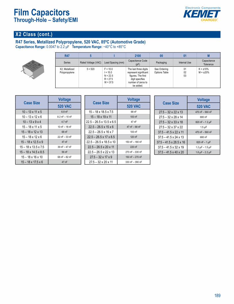
189
Film Capacitors
X2 Class (cont.) R47 Series, Metallized Polypropylene, 520 VAC, 85ºC (Automotive Grade)Capacitance Range: 0.0047 to 2.2 μF Temperature Range: −40°C to +85°C
• RoHS Co p r in
Pa t Num er System
R47 5 I 2100 00 01 M
Series Rated Voltage (VAC) Lead Spacing (mm) Capacitance Code (pF) Packaging Internal Use Capacitance
ToleranceX2, Metallized Polypropylene
5 = 520 F = 10.0I = 15.0N = 22.5R = 27 5W = 37.5
The last three digits represent signifi cant
fi gures. The fi rst digit specifi es
number of zeros to be added.
See Ordering Options Table
010203
K = ±10% M = ±20%
Case SizeVoltage520 VAC
10 – 13 x 11 x 5 6.8 nF
10 – 13 x 12 x 6 8.2 nF – 10 nF
10 – 13 x 9 x 4 4.7 nF
15 – 18 x 11 x 5 10 nF – 18 nF
15 – 18 x 12 x 13 68 nF
15 – 18 x 12 x 6 22 nF – 33 nF
15 – 18 x 12.5 x 9 47 nF
15 – 18 x 13.5 x 7.5 39 nF – 47 nF
15 – 18 x 14.5 x 8.5 56 nF
15 – 18 x 16 x 10 68 nF – 82 nF
15 – 18 x 17.5 x 6 47 nF
Case SizeVoltage520 VAC
15 – 18 x 18.5 x 7.5 68 nF
15 – 18 x 19 x 11 100 nF
22.5 – 26.5 x 13.5 x 6.5 47 nF
22.5 – 26.5 x 15 x 6 47 nF – 68 nF
22.5 – 26.5 x 16 x 7 100 nF
22.5 – 26.5 x 17 x 8.5 120 nF
22.5 – 26.5 x 18.5 x 10 150 nF – 180 nF
22.5 – 26.5 x 20 x 11 220 nF
22.5 – 26.5 x 22 x 13 270 nF – 330 nF
27.5 – 32 x 17 x 9 150 nF – 270 nF
27.5 – 32 x 20 x 11 330 nF – 390 nF
Case SizeVoltage520 VAC
27.5 – 32 x 22 x 13 470 nF – 560 nF
27.5 – 32 x 28 x 14 680 nF
27.5 – 32 x 33 x 18 820 nF – 1 2 µF
27.5 – 32 x 37 x 22 1.5 µF
37.5 – 41.5 x 22 x 11 470 nF – 560 nF
37.5 – 41.5 x 24 x 13 680 nF
37.5 – 41.5 x 28.5 x 16 820 nF – 1 µF
37.5 – 41.5 x 32 x 19 1.2 µF – 1.5 µF
37.5 – 41.5 x 40 x 20 1.8 µF – 2.2 µF
Through-Hole – Safety/EMI
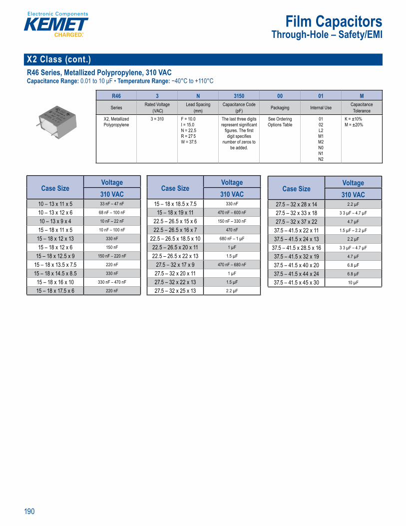
190
Film Capacitors
X2 Class (cont.)R46 Series, Metallized Polypropylene, 310 VACCapacitance Range: 0.01 to 10 μF • Temperature Range: −40°C to +110°C
Part N mber System
R46 3 N 3150 00 01 M
Series Rated Voltage (VAC)
Lead Spacing (mm)
Capacitance Code (pF) Packaging Internal Use Capacitance
ToleranceX2, Metallized Polypropylene
3 = 310 F = 10.0I = 15.0N = 22.5R = 27 5W = 37.5
The last three digits represent signifi cant
fi gures. The fi rst digit specifi es
number of zeros to be added.
See Ordering Options Table
0102L2M1M2N0N1N2
K = ±10% M = ±20%
Case SizeVoltage310 VAC
10 – 13 x 11 x 5 33 nF – 47 nF
10 – 13 x 12 x 6 68 nF – 100 nF
10 – 13 x 9 x 4 10 nF – 22 nF
15 – 18 x 11 x 5 10 nF – 100 nF
15 – 18 x 12 x 13 330 nF
15 – 18 x 12 x 6 150 nF
15 – 18 x 12.5 x 9 150 nF – 220 nF
15 – 18 x 13.5 x 7.5 220 nF
15 – 18 x 14.5 x 8.5 330 nF
15 – 18 x 16 x 10 330 nF – 470 nF
15 – 18 x 17.5 x 6 220 nF
Case SizeVoltage310 VAC
15 – 18 x 18.5 x 7.5 330 nF
15 – 18 x 19 x 11 470 nF – 600 nF
22.5 – 26.5 x 15 x 6 150 nF – 330 nF
22.5 – 26.5 x 16 x 7 470 nF
22.5 – 26.5 x 18.5 x 10 680 nF – 1 µF
22.5 – 26.5 x 20 x 11 1 µF
22.5 – 26.5 x 22 x 13 1.5 µF
27.5 – 32 x 17 x 9 470 nF – 680 nF
27.5 – 32 x 20 x 11 1 µF
27.5 – 32 x 22 x 13 1.5 µF
27.5 – 32 x 25 x 13 2.2 µF
Case SizeVoltage310 VAC
27.5 – 32 x 28 x 14 2.2 µF
27.5 – 32 x 33 x 18 3 3 µF – 4.7 µF
27.5 – 32 x 37 x 22 4.7 µF
37.5 – 41.5 x 22 x 11 1.5 µF – 2.2 µF
37.5 – 41.5 x 24 x 13 2.2 µF
37.5 – 41.5 x 28.5 x 16 3 3 µF – 4.7 µF
37.5 – 41.5 x 32 x 19 4.7 µF
37.5 – 41.5 x 40 x 20 6.8 µF
37.5 – 41.5 x 44 x 24 6.8 µF
37.5 – 41.5 x 45 x 30 10 µF
Through-Hole – Safety/EMI
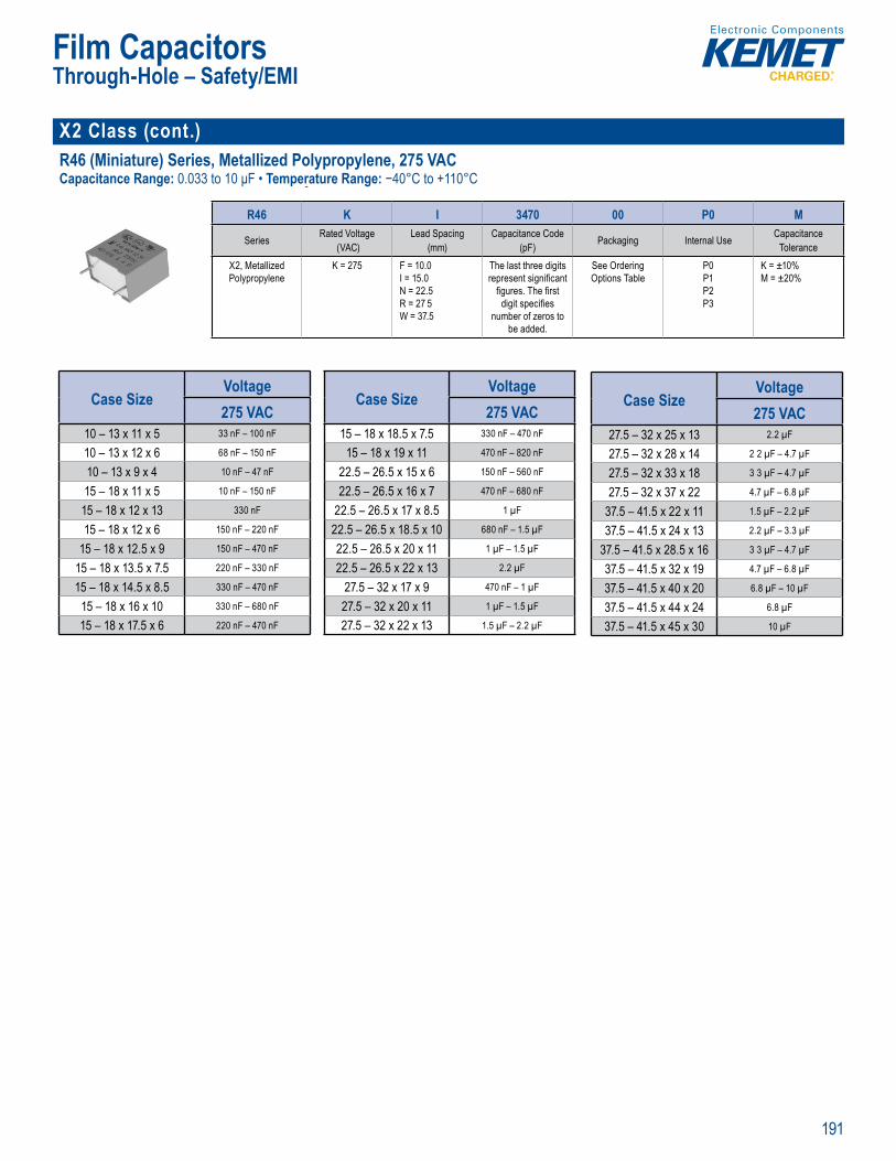
191
Film Capacitors
X2 Class (cont.)R46 (Miniature) Series, Metallized Polypropylene, 275 VACCapacitance Range: 0.033 to 10 μF • Temperature Range: −40°C to +110°C
• RoHS Co
P rt N mber System
R46 K I 3470 00 P0 M
Series Rated Voltage (VAC)
Lead Spacing (mm)
Capacitance Code (pF) Packaging Internal Use Capacitance
ToleranceX2, Metallized Polypropylene
K = 275 F = 10.0I = 15.0N = 22.5R = 27 5W = 37.5
The last three digits represent signifi cant
fi gures. The fi rst digit specifi es
number of zeros to be added.
See Ordering Options Table
P0P1P2P3
K = ±10% M = ±20%
Case SizeVoltage275 VAC
10 – 13 x 11 x 5 33 nF – 100 nF
10 – 13 x 12 x 6 68 nF – 150 nF
10 – 13 x 9 x 4 10 nF – 47 nF
15 – 18 x 11 x 5 10 nF – 150 nF
15 – 18 x 12 x 13 330 nF
15 – 18 x 12 x 6 150 nF – 220 nF
15 – 18 x 12.5 x 9 150 nF – 470 nF
15 – 18 x 13.5 x 7.5 220 nF – 330 nF
15 – 18 x 14.5 x 8.5 330 nF – 470 nF
15 – 18 x 16 x 10 330 nF – 680 nF
15 – 18 x 17.5 x 6 220 nF – 470 nF
Case SizeVoltage275 VAC
15 – 18 x 18.5 x 7.5 330 nF – 470 nF
15 – 18 x 19 x 11 470 nF – 820 nF
22.5 – 26.5 x 15 x 6 150 nF – 560 nF
22.5 – 26.5 x 16 x 7 470 nF – 680 nF
22.5 – 26.5 x 17 x 8.5 1 µF
22.5 – 26.5 x 18.5 x 10 680 nF – 1.5 µF
22.5 – 26.5 x 20 x 11 1 µF – 1.5 µF
22.5 – 26.5 x 22 x 13 2.2 µF
27.5 – 32 x 17 x 9 470 nF – 1 µF
27.5 – 32 x 20 x 11 1 µF – 1.5 µF
27.5 – 32 x 22 x 13 1.5 µF – 2.2 µF
Case SizeVoltage275 VAC
27.5 – 32 x 25 x 13 2.2 µF
27.5 – 32 x 28 x 14 2 2 µF – 4.7 µF
27.5 – 32 x 33 x 18 3 3 µF – 4.7 µF
27.5 – 32 x 37 x 22 4.7 µF – 6.8 µF
37.5 – 41.5 x 22 x 11 1.5 µF – 2.2 µF
37.5 – 41.5 x 24 x 13 2.2 µF – 3.3 µF
37.5 – 41.5 x 28.5 x 16 3 3 µF – 4.7 µF
37.5 – 41.5 x 32 x 19 4.7 µF – 6.8 µF
37.5 – 41.5 x 40 x 20 6.8 µF – 10 µF
37.5 – 41.5 x 44 x 24 6.8 µF
37.5 – 41.5 x 45 x 30 10 µF
Through-Hole – Safety/EMI
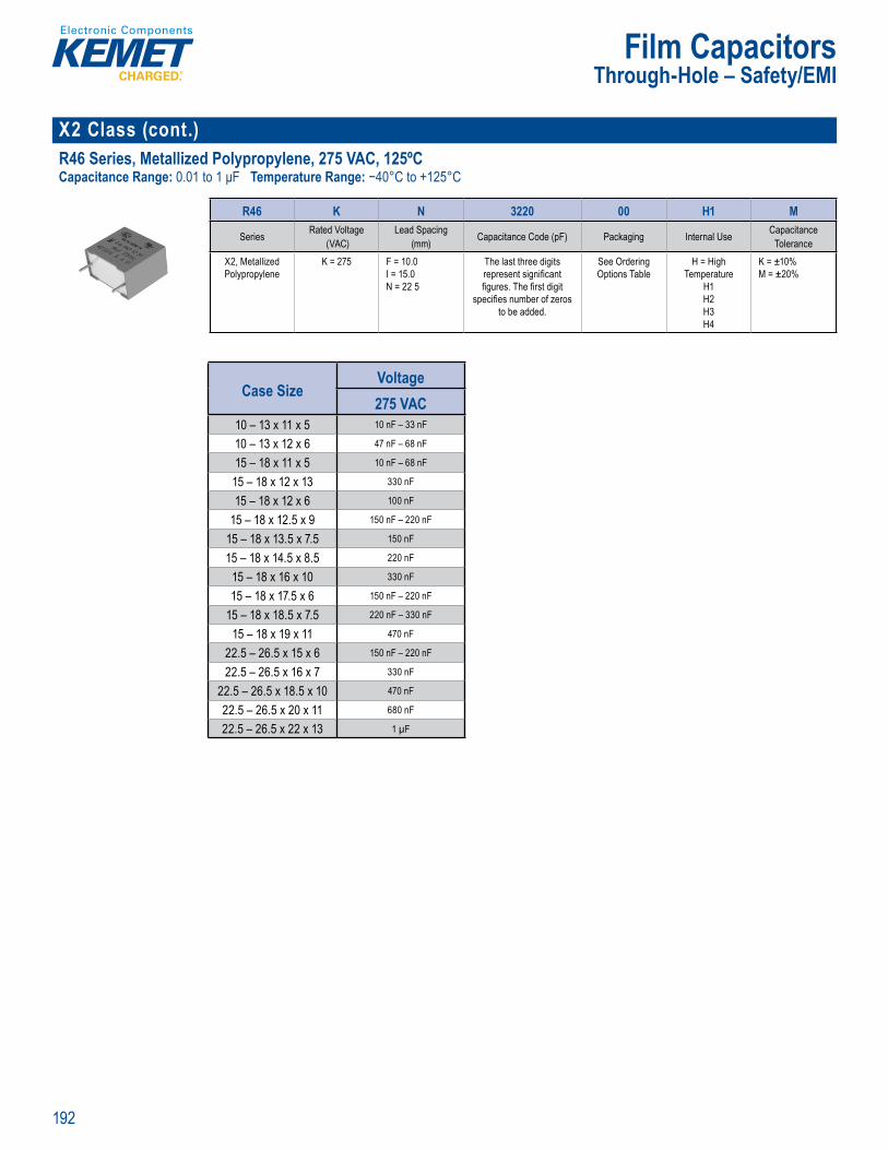
192
Film Capacitors
X2 Class (cont.)R46 Series, Metallized Polypropylene, 275 VAC, 125ºCCapacitance Range: 0.01 to 1 μF Temperature Range: −40°C to +125°C
Part Number Syst m
R46 K N 3220 00 H1 M
Series Rated Voltage (VAC)
Lead Spacing (mm) Capacitance Code (pF) Packaging Internal Use Capacitance
ToleranceX2, Metallized Polypropylene
K = 275 F = 10.0I = 15.0N = 22 5
The last three digits represent signifi cant fi gures. The fi rst digit
specifi es number of zeros to be added.
See Ordering Options Table
H = High Temperature
H1H2H3H4
K = ±10% M = ±20%
Case SizeVoltage275 VAC
10 – 13 x 11 x 5 10 nF – 33 nF
10 – 13 x 12 x 6 47 nF – 68 nF
15 – 18 x 11 x 5 10 nF – 68 nF
15 – 18 x 12 x 13 330 nF
15 – 18 x 12 x 6 100 nF
15 – 18 x 12.5 x 9 150 nF – 220 nF
15 – 18 x 13.5 x 7.5 150 nF
15 – 18 x 14.5 x 8.5 220 nF
15 – 18 x 16 x 10 330 nF
15 – 18 x 17.5 x 6 150 nF – 220 nF
15 – 18 x 18.5 x 7.5 220 nF – 330 nF
15 – 18 x 19 x 11 470 nF
22.5 – 26.5 x 15 x 6 150 nF – 220 nF
22.5 – 26.5 x 16 x 7 330 nF
22.5 – 26.5 x 18.5 x 10 470 nF
22.5 – 26.5 x 20 x 11 680 nF
22.5 – 26.5 x 22 x 13 1 µF
Through-Hole – Safety/EMI

193
Film Capacitors
X2 Class (cont.)PME264 Series Metallized Impregnated Paper, 660 VACCapacitance Range: 0.001 to 0 1 μF • Tempe atu e Range: −40°C to +85°C
Legacy Part Number System
a d o Capa itan
Legacy Part Number System
PME264 N B 5100 M R30
Series Rated Voltage (VAC) Lead Spacing (mm) Capacitance Code (pF) CapacitanceTolerance Packaging
X2, Metallized Paper N = 660 B = 15.2C = 20.3E = 25.4
The last three digits represent signifi cant fi gures. The fi rst digit
specifi es the total number of digits.
M = ±20% See Ordering Options Table
New KEMET Part Number System
Lead pa
Legacy Part Number System
Series ta c nce C cit cka
tall zed N = 660 15 2
E 5
The last th ee di its
r s h fi r t digit specifi es the total numb r o digi s
M = ±2 ee Orderin
New KEME Part Number System
P 264 Q E 103 M 660 ACapacitor
Class Series Lead Spacing (mm) Size Code Capacitance Code (pF) CapacitanceTolerance
Rated Voltage (VAC) Packaging
P = Paper X2, Metallized Paper
Q = 15 2C = 20.3E = 25.4
See Dimension Table
First two digits represent signifi cant fi gures. Third digit specifi es number of
zeros.
M = ±20% 660 = 660 See Ordering Options Table
Case SizeVoltage660 VAC
15.2 – 18.5 x 10.5 x 5.2 1 nF – 4.7 nF
15.2 – 18.5 x 13 x 7.3 6.8 nF – 10 nF
20.3 – 24 x 14 x 7.6 15 nF
20.3 – 24 x 15 x 9 22 nF
20.3 – 24 x 16.5 x 11.3 33 nF
25.4 – 30.5 x 17 x 10.5 47 nF
25.4 – 30.5 x 19 x 12.1 68 nF
25.4 – 30.5 x 22 x 15.3 100 nF
Through-Hole – Safety/EMI
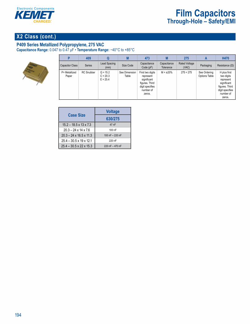
194
Film Capacitors
X2 Class (cont.)P409 Series Metallized Polypropylene, 275 VACCapacitance Range: 0.047 to 0.47 μF • Temperature Range: −40°C to +85°C
Part N e e
P 409 Q M 473 M 275 A H470
Capacitor Class Series Lead Spacing(mm) Size Code Capacitance
Code (pF)Capacitance
ToleranceRated Voltage
(VAC) Packaging Resistance (Ω)
P= Metallized Paper
RC Snubber Q = 15.2C = 20.3E = 25.4
See Dimension Table
First two digits represent signifi cant
fi gures. Third digit specifi es
number of zeros.
M = ±20% 275 = 275 See Ordering Options Table
H plus fi rst two digits represent signifi cant
fi gures. Third digit specifi es
number of zeros.
Case SizeVoltage630/275
15.2 – 18.5 x 13 x 7.3 47 nF
20.3 – 24 x 14 x 7.6 100 nF
20.3 – 24 x 16.5 x 11.3 100 nF – 220 nF
25.4 – 30.5 x 19 x 12.1 220 nF
25.4 – 30.5 x 22 x 15.3 220 nF – 470 nF
Through-Hole – Safety/EMI
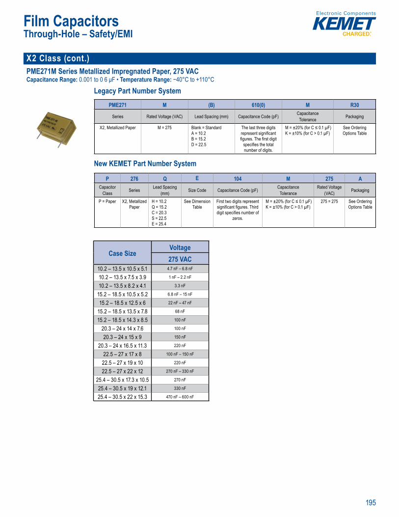
195
Film Capacitors
X2 Class (cont.) PME271M Series Metallized Impregnated Paper, 275 VACCapacitance Range: 0.001 to 0 6 μF • Temperature Range: −40°C to +110°C
Legacy Part Number System
ead spa Capa itan
• % s g o est D
Legacy Part Number System
PME271 M (B) 610(0) M R30
Series Rated Voltage (VAC) Lead Spacing (mm) Capacitance Code (pF) CapacitanceTolerance Packaging
X2, Metallized Paper M = 275 Blank = StandardA = 10.2B = 15.2D = 22.5
The last three digits represent signifi cant fi gures. The fi rst digit
specifi es the total number of digits.
M = ±20% (for C ≤ 0.1 µF)K = ±10% (for C > 0.1 µF)
See Ordering Options Table
New KEMET Part Number System
K = ± 0%
L gac art Number System
i cito rance
7 A
1 2D 22.5
T t ep e t a e st gi spec fi es he t tal
e f g t .
% (for C ≤ ( o )
d i O n
New KEME Part Number System
P 276 Q E 104 M 275 ACapacitor
Class Series Lead Spacing (mm) Size Code Capacitance Code (pF) Capacitance
ToleranceRated Voltage
(VAC) Packaging
P = Paper X2, Metallized Paper
H = 10.2Q = 15.2C = 20.3S = 22.5E = 25.4
See Dimension Table
First two digits represent signifi cant fi gures. Third digit specifi es number of
zeros.
M = ±20% (for C ≤ 0.1 µF)K = ±10% (for C > 0.1 µF)
275 = 275 See Ordering Options Table
Case SizeVoltage275 VAC
10.2 – 13.5 x 10.5 x 5.1 4.7 nF – 6.8 nF
10.2 – 13.5 x 7.5 x 3.9 1 nF – 2.2 nF
10.2 – 13.5 x 8.2 x 4.1 3.3 nF
15.2 – 18.5 x 10.5 x 5.2 6.8 nF – 15 nF
15.2 – 18.5 x 12.5 x 6 22 nF – 47 nF
15.2 – 18.5 x 13.5 x 7.8 68 nF
15.2 – 18.5 x 14.3 x 8.5 100 nF
20.3 – 24 x 14 x 7.6 100 nF
20.3 – 24 x 15 x 9 150 nF
20.3 – 24 x 16.5 x 11.3 220 nF
22.5 – 27 x 17 x 8 100 nF – 150 nF
22.5 – 27 x 19 x 10 220 nF
22.5 – 27 x 22 x 12 270 nF – 330 nF
25.4 – 30.5 x 17.3 x 10.5 270 nF
25.4 – 30.5 x 19 x 12.1 330 nF
25.4 – 30.5 x 22 x 15.3 470 nF – 600 nF
Through-Hole – Safety/EMI
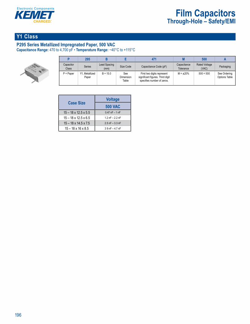
196
Film Capacitors
Y1 ClassP295 Series Metallized Impregnated Paper, 500 VACCapacitance Range: 470 to 4,700 pF • Temperature Range: −40°C to +115°C
Part Nu ber System
P 295 B E 471 M 500 ACapacitor
Class Series Lead Spacing (mm) Size Code Capacitance Code (pF) Capacitance
ToleranceRated Voltage
(VAC) Packaging
P = Paper Y1, Metallized Paper
B = 15.0 See Dimension
Table
First two digits represent signifi cant fi gures. Third digit specifi es number of zeros.
M = ±20% 500 = 500 See Ordering Options Table
Case SizeVoltage500 VAC
15 – 18 x 12.5 x 5.5 0.47 nF – 1 nF
15 – 18 x 12.5 x 6.5 1.2 nF – 2.2 nF
15 – 18 x 14.5 x 7.5 2.5 nF – 3.3 nF
15 – 18 x 16 x 8.5 3 9 nF – 4.7 nF
Through-Hole – Safety/EMI
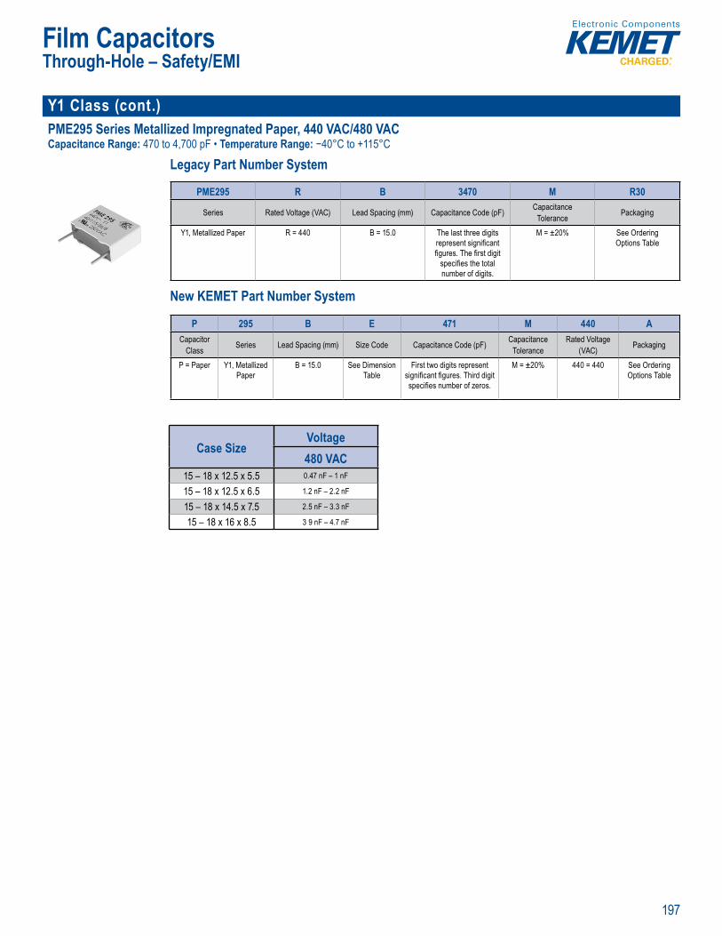
197
Film Capacitors
Y1 Class (cont.)PME295 Series Metallized Impregnated Paper, 440 VAC/480 VACCapacitance Range: 470 to 4,700 pF • Temperature Range: −40°C to +115°C
Legacy Part Number System
• Capacitan l
Legacy Part Number System
PME295 R B 3470 M R30
Series Rated Voltage (VAC) Lead Spacing (mm) Capacitance Code (pF) CapacitanceTolerance Packaging
Y1, Metallized Paper R = 440 B = 15.0 The last three digits represent signifi cant fi gures. The fi rst digit
specifi es the total number of digits.
M = ±20% See Ordering Options Table
New KEMET Part Number System
Clima c c
L a y
Toler nce
epresent sign fi cant fi ures The fi rst digit
specifi es the total number of d gits
Options Table
New KEMET Part Number System
P 295 B E 471 M 440 ACapacitor
Class Series Lead Spacing (mm) Size Code Capacitance Code (pF) CapacitanceTolerance
Rated Voltage (VAC) Packaging
P = Paper Y1, Metallized Paper
B = 15.0 See Dimension Table
First two digits represent signifi cant fi gures. Third digit specifi es number of zeros.
M = ±20% 440 = 440 See Ordering Options Table
Case SizeVoltage480 VAC
15 – 18 x 12.5 x 5.5 0.47 nF – 1 nF
15 – 18 x 12.5 x 6.5 1.2 nF – 2.2 nF
15 – 18 x 14.5 x 7.5 2.5 nF – 3.3 nF
15 – 18 x 16 x 8.5 3 9 nF – 4.7 nF
Through-Hole – Safety/EMI
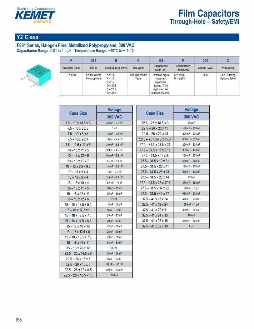
198
Film Capacitors
Y2 Class F881 Series, Halogen Free, Metallized Polypropylene, 300 VACCapacitance Range: 0.01 to 1 0 μF Temperature Range: −40°C to +110°C
Par Number System
F 881 B C 103 M 300 C
Capacitor Class Series Lead Spacing (mm) Size Code Capacitance Code (pF)
CapacitanceTolerance Voltage (VAC) Packaging
F = Film Y2, Metallized Polypropylene
K = 7 5A = 10B = 15D = 22.5F = 27 5R = 37.5
See Dimension Table
First two digits represent signifi cant
fi gures. Third digit specifi es
number of zeros.
K = ±10% M = ±20%
300 See Ordering Options Table
Case SizeVoltage300 VAC
7.5 – 10 x 10.5 x 5 2.5 nF – 3.9 nF
7.5 – 10 x 8 x 3 1 nF
7.5 – 10 x 8 x 4 1.2 nF – 1.5 nF
7.5 – 10 x 9 x 4 1.8 nF – 2.2 nF
7.5 – 10.5 x 12 x 6 3.9 nF – 5.6 nF
10 – 13 x 11 x 5 3.3 nF – 4.7 nF
10 – 13 x 12 x 6 5.6 nF – 6.8 nF
10 – 13 x 17 x 7 8.2 nF – 10 nF
10 – 13 x 7.5 x 9.5 1.8 nF – 6.8 nF
10 – 13 x 8 x 4 1 nF – 2 2 nF
10 – 13 x 9 x 4 2.5 nF – 2.7 nF
15 – 18 x 10 x 4 2.7 nF – 10 nF
15 – 18 x 11 x 5 10 nF – 15 nF
15 – 18 x 12 x 13 25 nF – 56 nF
15 – 18 x 12 x 6 22 nF
15 – 18 x 12.5 x 5.5 15 nF – 18 nF
15 – 18 x 12.5 x 9 15 nF – 39 nF
15 – 18 x 13.5 x 7.5 25 nF – 27 nF
15 – 18 x 14.5 x 8.5 39 nF – 47 nF
15 – 18 x 16 x 10 47 nF – 56 nF
15 – 18 x 17.5 x 6 25 nF – 39 nF
15 – 18 x 18.5 x 7.5 33 nF – 56 nF
15 – 18 x 19 x 11 68 nF – 82 nF
15 – 18 x 20 x 12 82 nF
22.5 – 26 x 14.5 x 6 39 nF – 56 nF
22.5 – 26 x 16 x 7 56 nF – 82 nF
22.5 – 26 x 16 x 8 82 nF – 100 nF
22.5 – 26 x 17 x 8.5 100 nF – 120 nF
22.5 – 26 x 18.5 x 10 150 nF
Case SizeVoltage300 VAC
22.5 – 26 x 18.5 x 9 120 nF
22.5 – 26 x 20 x 11 180 nF – 220 nF
22.5 – 26 x 22 x 13 220 nF – 270 nF
22.5 – 26 x 24.5 x 15.5 330 nF – 390 nF
27.5 – 31.5 x 12.5 x 21 220 nF – 330 nF
27.5 – 31.5 x 16 x 27.5 390 nF – 470 nF
27.5 – 31.5 x 17 x 9 100 nF – 150 nF
27.5 – 31.5 x 19 x 31 560 nF – 820 nF
27.5 – 31.5 x 20 x 11 180 nF – 270 nF
27.5 – 31.5 x 25 x 13 270 nF – 390 nF
27.5 – 31.5 x 28 x 14 560 nF
27.5 – 31.5 x 28 x 17.5 470 nF – 680 nF
27.5 – 31.5 x 37 x 22 820 nF – 1 µF
27.5 – 31.5 x 40 x 17 680 nF – 820 nF
37.5 – 41 x 15 x 24 470 nF – 560 nF
37.5 – 41 x 19 x 24 680 nF – 1 µF
37.5 – 41 x 22 x 11 330 nF – 390 nF
37.5 – 41 x 24 x 13 470 nF
37.5 – 41 x 26 x 15 560 nF – 820 nF
37.5 – 41 x 32 x 19 1 µF
Through-Hole – Safety/EMI

199
Film Capacitors
Y2 Class (cont.)R41 Series, Metallized Polypropylene, 300 VAC (Automotive Grade)Capacitance Range: 0.001 to 1 μF • Temperature Range: −40°C to +110°C
• RoHS Co i
P rt N mber System
R41 3 I 2330 00 M1 M
Series Rated Voltage (VAC)
Lead Spacing (mm)
Capacitance Code (pF) Packaging Internal Use Capacitance
ToleranceY2, Metallized Polypropylene
3 = 300 F = 10.0I = 15.0N = 22.5R = 27 5W = 37.5
The last three digits represent signifi cant
fi gures. The fi rst digit specifi es
number of zeros to be added.
See Ordering Options Table
00M1
K = ±10% M = ±20%
Case SizeVoltage300 VAC
10 – 13 x 11 x 5 4.7 nF
10 – 13 x 12 x 6 6.8 nF
10 – 13 x 9 x 4 1 nF – 3.3 nF
15 – 18 x 11 x 5 3.3 nF – 15 nF
15 – 18 x 12 x 6 22 nF
15 – 18 x 14.5 x 8.5 33 nF – 47 nF
15 – 18 x 19 x 11 68 nF
22.5 – 26.5 x 15 x 6 47 nF – 68 nF
22.5 – 26.5 x 16 x 7 68 nF
22.5 – 26.5 x 17 x 8.5 100 nF
22.5 – 26.5 x 18.5 x 10 150 nF
22.5 – 26.5 x 22 x 13 220 nF
27.5 – 32 x 22 x 13 220 nF
27.5 – 32 x 28 x 14 330 nF
27.5 – 32 x 33 x 18 470 nF – 680 nF
37.5 – 41.5 x 24 x 13 470 nF
37.5 – 41.5 x 28.5 x 16 680 nF
37.5 – 41.5 x 40 x 20 1 µF
Through-Hole – Safety/EMI
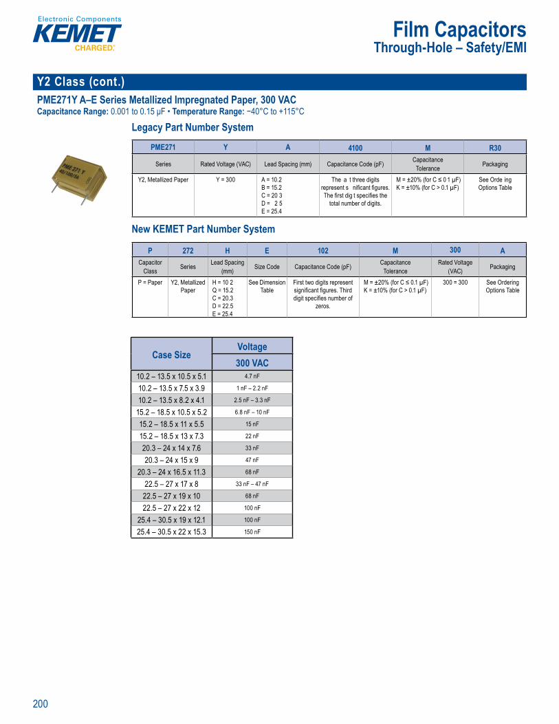
200
Film Capacitors
Y2 Class (cont.)PME271Y A–E Series Metallized Impregnated Paper, 300 VACCapacitance Range: 0.001 to 0.15 μF • Temperature Range: −40°C to +115°C
Legacy Part Number System
he hig e t ossible afety regar ing a t ve and p ssive fl
Legacy Part Number System
PME271 Y A 4100 M R30
Series Rated Voltage (VAC) Lead Spacing (mm) Capacitance Code (pF) CapacitanceTolerance Packaging
Y2, Metallized Paper Y = 300 A = 10.2B = 15.2C = 20 3D = 2 5E = 25.4
The a t three digits represent s nifi cant fi gures. The fi rst dig t specifi es the
total number of digits.
M = ±20% (for C ≤ 0 1 µF)K = ±10% (for C > 0.1 µF)
See Orde ing Options Table
= 2 .
o
New KEMET Part Number System
L e
itTolerance
B = 15.2C = 20 3D = 22 5E = 25 4
sent signifi cant fi gu
he fi rst dig t specifi es the to al number o digits.
% f r C ≤ K = ±10% (for C > 1 µF)
Options Table
New KEME Part Number System
P 272 H E 102 M 300 ACapacitor
Class Series Lead Spacing (mm) Size Code Capacitance Code (pF) Capacitance
ToleranceRated Voltage
(VAC) Packaging
P = Paper Y2, Metallized Paper
H = 10 2Q = 15.2C = 20.3D = 22.5E = 25.4
See Dimension Table
First two digits represent signifi cant fi gures. Third digit specifi es number of
zeros.
M = ±20% (for C ≤ 0.1 µF)K = ±10% (for C > 0.1 µF)
300 = 300 See Ordering Options Table
Case SizeVoltage300 VAC
10.2 – 13.5 x 10.5 x 5.1 4.7 nF
10.2 – 13.5 x 7.5 x 3.9 1 nF – 2.2 nF
10.2 – 13.5 x 8.2 x 4.1 2.5 nF – 3.3 nF
15.2 – 18.5 x 10.5 x 5.2 6.8 nF – 10 nF
15.2 – 18.5 x 11 x 5.5 15 nF
15.2 – 18.5 x 13 x 7.3 22 nF
20.3 – 24 x 14 x 7.6 33 nF
20.3 – 24 x 15 x 9 47 nF
20.3 – 24 x 16.5 x 11.3 68 nF
22.5 – 27 x 17 x 8 33 nF – 47 nF
22.5 – 27 x 19 x 10 68 nF
22.5 – 27 x 22 x 12 100 nF
25.4 – 30.5 x 19 x 12.1 100 nF
25.4 – 30.5 x 22 x 15.3 150 nF
Through-Hole – Safety/EMI

201
Film Capacitors
Y2 Class (cont.)PME271Y Series Metallized Impregnated Paper, 250 VACCapacitance Range: 0.001 to 0 1 μF • Temperature Range: −40°C to +100°C
Legacy Part Number System
Clima c c
Legacy Part Number System
PME271 Y 410 M R30
Series Rated Voltage (VAC) Capacitance Code (pF) CapacitanceTolerance Packaging
Y2, Metallized Paper Y = 250 The last two digits represent signifi cant fi gures. The
fi rst digit specifi es the total number of digits.
M = ±20% See Ordering Options Table
New KEMET Part Number System
Tape nd
L ga art Number Syste
citTol ance
5 u
st digit speci es t t n f d it
M = ±20% d O n
New KEMET Part Number System
P 271 H E 102 M 250 ACapacitor
Class Series Lead Spacing (mm) Size Code Capacitance Code (pF) CapacitanceTolerance
Rated Voltage (VAC)
Lead and Packaging Code
P = Paper Y2, Metallized Paper
H = 10.2Q = 15.2C = 20.3E = 25.4
See Dimension Table
First two digits represent signifi cant fi gures. Third digit specifi es number of zeros.
M = ±20% 250 = 250 See Ordering Options Table
Case SizeVoltage250 VAC
10.2 – 13.5 x 10.5 x 5.1 4.7 nF
10.2 – 13.5 x 7.5 x 3.9 1 nF – 2.2 nF
10.2 – 13.5 x 8.2 x 4.1 3.3 nF
15.2 – 18.5 x 10.5 x 5.2 6.8 nF – 10 nF
15.2 – 18.5 x 11 x 5.5 15 nF
15.2 – 18.5 x 13 x 7.3 22 nF
20.3 – 24 x 14 x 7.6 33 nF
20.3 – 24 x 15 x 9 47 nF
20.3 – 24 x 16.5 x 11.3 68 nF
25.4 – 30.5 x 19 x 12.1 100 nF
Through-Hole – Safety/EMI

202
Film Capacitors
Multiple X & Y PHZ9004 Series Metallized Polypropylene Film, 300 VAC 3x X2 with Separate Terminals for Three-Phase FilteringCapacitance Range: 3 x 1.0 μF • Temperature Range: −55°C to +105°C
Legacy Part Number System
Legacy Part Number System
PHZ9004 E F 7100 M R06L2
Series Rated Voltage (VAC) Lead Spacing (mm) Capac tance Co e (pF) CapacitanceTolerance Packaging
Trip e Capacitor X2, Metallized Polypropylene
E = 300 F = 27 5 The last three dig ts represent signifi cant fi gures The fi rst digit
specifi es the total number of digits.
M = ±20% See Ordering Options Table
New KEMET Part Number System
Le acy Part Number S tem
Series ta c nce C c t ackagin
e Capa
Polypropylene
E = 300 F = 27 5 he last th ee di its
fi gures. he fi rst digit specifi es the total number o digi s.
ee Orderin
New KEME Part Number System
9004 AA 105 M 300 C DECT V680
Capacitor Class Size Code Capacitance Code (pF) CapacitanceTolerance
Rated Voltage (VAC) Packaging C-Spec V-Spec
Triple Capacitor X2,
Metallized Polypropylene
See Dimension
Table
First two digits represent signifi cant fi gures. Third digit specifi es number of zeros.
M = ±20% 300 = 300 See Ordering Options Table
Optional additional
characters at KEMET’s option.
Part Number specifi c version
code
Case SizeVoltage300 VAC
27.5 – 64 x 11.5 x 30 1 µF
Through-Hole – Safety/EMI
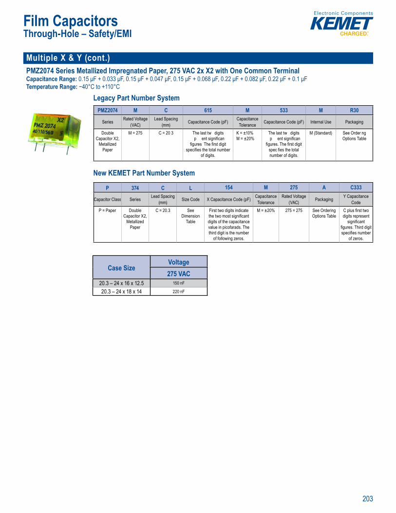
203
Film Capacitors
Multiple X & Y (cont.)PMZ2074 Series Metallized Impregnated Paper, 275 VAC 2x X2 with One Common TerminalCapacitance Range: 0.15 μF + 0.033 μF, 0.15 μF + 0.047 μF, 0.15 μF + 0.068 μF, 0.22 μF + 0.082 μF, 0.22 μF + 0.1 μFTemperature Range: −40°C to +110°C
Legacy Part Number System
• at d vo a a ita
i a S
• O e ating te pe ature ange of - 0 C to +110˚• 1 0% sc e n ac ory est t , 5 VDC
Legacy Part Number System
PMZ2074 M C 615 M 533 M R30
Series Rated Voltage (VAC)
Lead Spacing (mm) Capacitance Code (pF) Capacitance
Tolerance Capacitance Code (pF) Internal Use Packaging
Double Capacitor X2,
Metallized Paper
M = 275 C = 20 3 The last tw digits p ent signifi can
fi gures The fi rst digit specifi es the total number
of digits.
K = ±10%M = ±20%
The last tw digits p ent signifi can
fi gures. The fi rst digit spec fi es the total number of digits.
M (Standard) See Order ng Options Table
New KEMET Part Number System
Capacitan
• Ro S
• 100% screen ng factory test at 2,1 0 VD
P
(VAC)
(mm) Tolerance
pacitor
Metallized Paper
75 = 2 present signifi can
fi gures. The fi rst digit ecifi es t e total numb
of d gits.
%M = ±2
present signifi can
fi gures. The fi rst digit spec es t e total number of d gits.
Options Tab e
New KEME Part Number System
P 374 C L 154 M 275 A C333
Capacitor Class Series Lead Spacing(mm) Size Code X Capacitance Code (pF) Capacitance
ToleranceRated Voltage
(VAC) Packaging Y Capacitance Code
P = Paper Double Capacitor X2,
Metallized Paper
C = 20.3 See Dimension
Table
First two digits indicate the two most signifi cant digits of the capacitance value in picofarads. The third digit is the number
of following zeros.
M = ±20% 275 = 275 See Ordering Options Table
C plus fi rst two digits represent
signifi cant fi gures. Third digit specifi es number
of zeros.
Case SizeVoltage275 VAC
20.3 – 24 x 16 x 12.5 150 nF
20.3 – 24 x 18 x 14 220 nF
Through-Hole – Safety/EMI
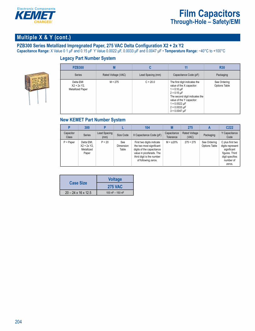
204
Film Capacitors
Multiple X & Y (cont.) PZB300 Series Metallized Impregnated Paper, 275 VAC Delta Configuration X2 + 2x Y2Capacitance Range: X Value 0 1 μF and 0.15 μF Y Value 0.0022 μF, 0.0033 μF and 0.0047 μF • Temperature Range: −40°C to +100°C
Legacy Part Number System
• Cap c
Legacy Part Number System
PZB300 M C 11 R30
Series Rated Voltage (VAC) Lead Spacing (mm) Capacitance Code (pF) Packaging
Delta EMIX2 + 2x Y2,
Metallized Paper
M = 275 C = 20.0 The fi rst digit indicates the value of the X capacitor: 1 = 0.10 µF2 = 0.15 µFThe second digit indicates the value of the Y capacitor:1 = 0.0022 µF2 = 0.0033 µF3 = 0.0047 µF
See Ordering Options Table
New KEMET Part Number System
Le ac Part N mbe Sys em
Serie t c cka
lta EM
t lliz d Pap
= 275 C = 20 0 e fi rst digit indi tes t e
1 = 10 µF 1 F
T o v l o th 1 2 F
F 7 µF
e Orderin
New KEME Part Number System
P 300 P L 104 M 275 A C222Capacitor
Class Series Lead Spacing (mm) Size Code X Capacitance Code (pF) Capacitance
ToleranceRated Voltage
(VAC) Packaging Y Capacitance Code
P = Paper Delta EMI,X2 + 2x Y2, Metallized
Paper
P = 20 See Dimension
Table
First two digits indicate the two most signifi cant digits of the capacitance value in picofarads. The third digit is the number
of following zeros.
M = ±20% 275 = 275 See Ordering Options Table
C plus fi rst two digits represent
signifi cant fi gures. Third digit specifi es
number of zeros.
Case SizeVoltage275 VAC
20 – 24 x 16 x 12.5 100 nF – 150 nF
Through-Hole – Safety/EMI
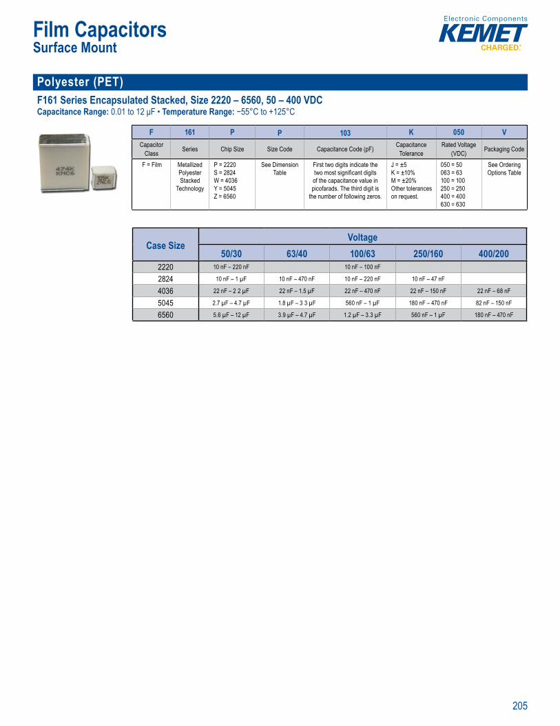
205
Film Capacitors
Polyester (PET) F161 Series Encapsulated Stacked, Size 2220 – 6560, 50 – 400 VDCCapacitance Range: 0.01 to 12 μF • Temperature Range: −55°C to +125°C
Climatic c
Part N mber System
F 161 P P 103 K 050 VCapacitor
Class Series Chip Size Size Code Capacitance Code (pF) CapacitanceTolerance
Rated Voltage (VDC) Packaging Code
F = Film Metallized Polyester Stacked
Technology
P = 2220S = 2824W = 4036Y = 5045Z = 6560
See Dimension Table
First two digits indicate the two most signifi cant digits of the capacitance value in picofarads. The third digit is
the number of following zeros.
J = ±5K = ±10% M = ±20% Other tolerances on request.
050 = 50063 = 63100 = 100250 = 250400 = 400630 = 630
See Ordering Options Table
Case SizeVoltage
50/30 63/40 100/63 250/160 400/2002220 10 nF – 220 nF 10 nF – 100 nF
2824 10 nF – 1 µF 10 nF – 470 nF 10 nF – 220 nF 10 nF – 47 nF
4036 22 nF – 2 2 µF 22 nF – 1.5 µF 22 nF – 470 nF 22 nF – 150 nF 22 nF – 68 nF
5045 2.7 µF – 4.7 µF 1.8 µF – 3 3 µF 560 nF – 1 µF 180 nF – 470 nF 82 nF – 150 nF
6560 5.6 µF – 12 µF 3.9 µF – 4.7 µF 1.2 µF – 3.3 µF 560 nF – 1 µF 180 nF – 470 nF
Surface Mount
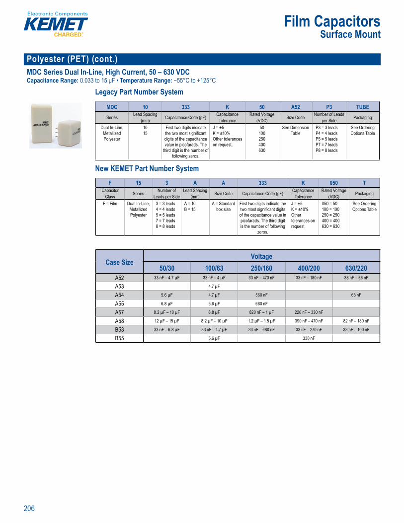
206
Film Capacitors
Polyester (PET) (cont.)MDC Series Dual In-Line, High Current, 50 – 630 VDC Capacitance Range: 0.033 to 15 μF • Temperature Range: −55°C to +125°C
Legacy Part Number System
Legacy Part Number System
MDC 10 333 K 50 A52 P3 TUBESeries Lead Spacing
(mm) Capacitance Code (pF) CapacitanceTolerance
Rated Voltage (VDC) Size Code Number of Leads
per Side Packaging
Dual In-Line, Metallized Polyester
1015
First two digits indicate the two most signifi cant digits of the capacitance value in picofarads. The
third digit is the number of following zeros.
J = ±5K = ±10% Other tolerances on request.
50100250400630
See Dimension Table
P3 = 3 leadsP4 = 4 leadsP5 = 5 leadsP7 = 7 leadsP8 = 8 leads
See Ordering Options Table
New KEMET Part Number System
L gac Part Numbe Syste
Serie p n e C i ze Co o ckag n
al In-L
Po yester
1015
First two dig ts ind cate
digits of the capacitance value in picofarads The hird dig t is the number o
following zeros
5
Ot er on equ st
5400630
ee Dimensi P3 d =
P5 5 eadsP7 = 7 leadsP8 8 eads
ee O derin
New KEMET Part Number System
F 15 3 A A 333 K 050 TCapacitor
Class Series Number of Leads per Side
Lead Spacing (mm) Size Code Capacitance Code (pF) Capacitance
ToleranceRated Voltage
(VDC) Packaging
F = Film Dual In-Line,Metallized Polyester
3 = 3 leads4 = 4 leads5 = 5 leads7 = 7 leads8 = 8 leads
A = 10B = 15
A = Standard box size
First two digits indicate the two most signifi cant digits of the capacitance value in picofarads. The third digit is the number of following
zeros.
J = ±5K = ±10% Other tolerances on request
050 = 50100 = 100250 = 250400 = 400630 = 630
See Ordering Options Table
Case SizeVoltage
50/30 100/63 250/160 400/200 630/220A52 33 nF – 4.7 µF 33 nF – 4 µF 33 nF – 470 nF 33 nF – 180 nF 33 nF – 56 nF
A53 4.7 µF
A54 5.6 µF 4.7 µF 560 nF 68 nF
A55 6.8 µF 5.6 µF 680 nF
A57 8.2 µF – 10 µF 6.8 µF 820 nF – 1 µF 220 nF – 330 nF
A58 12 µF – 15 µF 8.2 µF – 10 µF 1.2 µF – 1.5 µF 390 nF – 470 nF 82 nF – 180 nF
B53 33 nF – 6.8 µF 33 nF – 4.7 µF 33 nF – 680 nF 33 nF – 270 nF 33 nF – 100 nF
B55 5.6 µF 330 nF
Surface Mount

207
Film Capacitors
Polyester (PET) (cont.) MDS Series Dual In-Line Low Profile, High Current, 50 – 630 VDCCapacitance Range: 0.033 to 6 8 μF • Tempe ature Range: −55°C to +125°C
Legacy Part Number System
C pa itan
Legacy Part Number System
MDS 10 333 K 50 A52 P3 TUBESeries Lead Spacing
(mm) Capacitance Code (pF) CapacitanceTolerance
Rated Voltage (VDC) Size Code Number of Leads
per Side Packaging
Dual In-Line, Metallized Polyester
1015
First two digits indicate the two most signifi cant digits of the capacitance value in picofarads. The
third digit is the number of following zeros.
J ±5K = ±10% Other tolerances on request.
050 = 50100 = 100250 = 250400 = 400630 = 630
See Dimension Table
P3 = 3 leadsP4 = 4 leadsP5 = 5 leads
See Ordering Options Table
New KEMET Part Number System
• Climatic c oHS Co
Lega y Part Number System
Series p nce C i e Co r o ac agin
al In Li
Po yester
1015
First two dig ts ind cate
di its of the capacitance value in picofarads The hird d g t is the number o
following zeros
5 10%
Other o equ st
5 = 1 0
250 25400 400630 630
e Dimensi P3 d = 4 e ds
P5 5 leads
ee Orderin
New KEMET Part Number System
F 17 3 A A 333 K 050 TCapacitor Class Series Number of
Leads per SideLead Spacing
(mm) Size Code Capacitance Code (pF) CapacitanceTolerance
Rated Voltage (VDC) Packaging
F = Film Dual In-Line,Metallized Polyester
3 = 3 leads4 = 4 leads5 = 5 leads
A = 10B = 15
A = Standard box size
First two digits indicate the two most signifi cant digits of the capacitance value in picofarads. The third digit is the number of following
zeros.
J = ±5K = ±10% Other tolerances on request
050 = 50100 = 100250 = 250400 = 400630 = 630
See Ordering Options Table
Case SizeVoltage
50/30 100/63 250/160 400/200 630/220A52 33 nF – 4.7 µF 33 nF – 3.9 µF 33 nF – 470 nF 33 nF – 180 nF 33 nF – 56 nF
A54 5.6 µF 4.7 µF 560 nF 68 nF
A55 6.8 µF 5.6 µF 680 nF
B53 33 nF – 6.8 µF 33 nF – 4.7 µF 33 nF – 680 nF 33 nF – 270 nF 33 nF – 100 nF
B55 5.6 µF 330 nF
Surface Mount
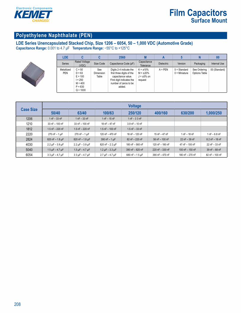
208
Film Capacitors
Polyethylene Naphthalate (PEN)LDE Series Unencapsulated Stacked Chip, Size 1206 – 6054, 50 – 1,000 VDC (Automotive Grade)Capacitance Range: 0.001 to 4.7 μF Temperature Range: −55°C to +125°C
Part umber System
LDE C C 2560 M A 5 N 00Series Rated Voltage
(VDC) Size Code Capacitance Code (pF) CapacitanceTolerance Dielectric Version Packaging Internal Use
Metallized PEN
C = 50D = 63E = 100I = 250M = 400P = 630Q = 1000
See Dimension
Table
Digits 2-4 indicate the fi rst three digits of the
capacitance value. First digit indicates the number of zeros to be
added.
K = ±10% M = ±20%J = ±5% on request
A = PEN 5 = Standard0 = Miniature
See Ordering Options Table
00 (Standard)
Case SizeVoltage
50/40 63/40 100/63 250/120 400/160 630/200 1,000/2501206 1 nF – 33 nF 1 nF – 33 nF 1 nF – 15 nF 1 nF – 3 3 nF
1210 33 nF – 100 nF 33 nF – 100 nF 18 nF – 47 nF 3.9 nF – 10 nF
1812 1.5 nF – 220 nF 1.5 nF – 220 nF 1.5 nF – 100 nF 1.5 nF – 33 nF
2220 270 nF – 1 µF 270 nF – 1 µF 120 nF – 470 nF 18 nF – 120 nF 15 nF – 47 nF 1 nF – 18 nF 1 nF – 6.8 nF
2824 820 nF – 1.8 µF 820 nF – 1.8 µF 390 nF – 1 µF 82 nF – 220 nF 56 nF – 100 nF 22 nF – 39 nF 8.2 nF – 18 nF
4030 2.2 µF – 3.9 µF 2.2 µF – 3.9 µF 820 nF – 2 2 µF 180 nF – 560 nF 120 nF – 180 nF 47 nF – 100 nF 22 nF – 33 nF
5040 1 5 µF – 4.7 µF 1.5 µF – 4.7 µF 1.2 µF – 3.3 µF 390 nF – 820 nF 220 nF – 330 nF 100 nF – 150 nF 39 nF – 68 nF
6054 3 3 µF – 4.7 µF 3 3 µF – 4.7 µF 2.7 µF – 4.7 µF 680 nF – 1 5 µF 390 nF – 470 nF 180 nF – 270 nF 82 nF – 100 nF
Surface Mount
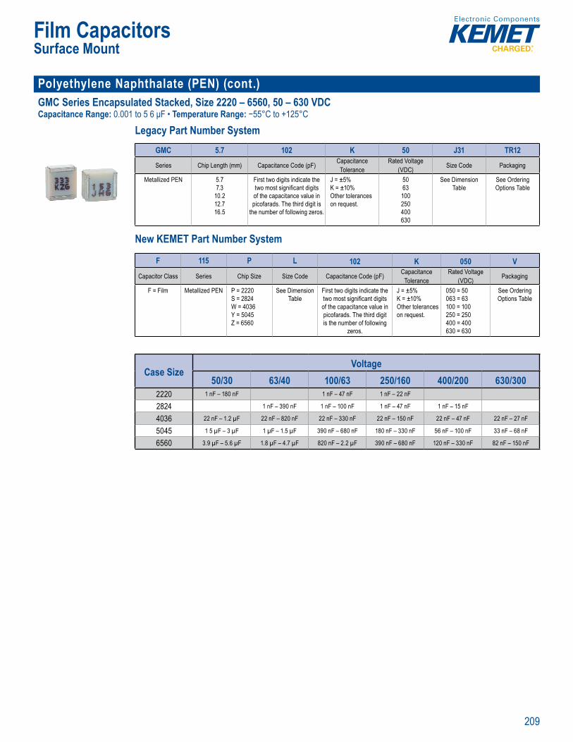
209
Film Capacitors
Polyethylene Naphthalate (PEN) (cont.)GMC Series Encapsulated Stacked, Size 2220 – 6560, 50 – 630 VDCCapacitance Range: 0.001 to 5 6 μF • Temperature Range: −55°C to +125°C
Legacy Part Number System
p EIA s e:
Legacy Part Number System
GMC 5.7 102 K 50 J31 TR12
Series Chip Length (mm) Capacitance Code (pF) CapacitanceTolerance
Rated Voltage (VDC) Size Code Packaging
Metallized PEN 5.77.3
10.212.716.5
First two digits indicate the two most signifi cant digits of the capacitance value in picofarads. The third digit is
the number of following zeros.
J = ±5% K = ±10%Other tolerances on request.
5063100250400630
See Dimension Table
See Ordering Options Table
New KEMET Part Number System
C pa itan
L ga y art Number Syste
Ser es eng ce C cio rance
d Vo (VDC) e Co ckagin
llized 5 73
21 5
rst two d gits indic te th t s g n g t f cit l i i d T i d digit i e u be f f ll n ze
l
5
63
e Dim nsi ee Orderin O n b
New KEMET Part Number System
F 115 P L 102 K 050 VCapacitor Class Series Chip Size Size Code Capacitance Code (pF) Capacitance
ToleranceRated Voltage
(VDC) Packaging
F = Film Metallized PEN P = 2220S = 2824W = 4036Y = 5045Z = 6560
See Dimension Table
First two digits indicate the two most signifi cant digits of the capacitance value in picofarads. The third digit is the number of following
zeros.
J = ±5% K = ±10%Other tolerances on request.
050 = 50063 = 63100 = 100250 = 250400 = 400630 = 630
See Ordering Options Table
Case SizeVoltage
50/30 63/40 100/63 250/160 400/200 630/3002220 1 nF – 180 nF 1 nF – 47 nF 1 nF – 22 nF
2824 1 nF – 390 nF 1 nF – 100 nF 1 nF – 47 nF 1 nF – 15 nF
4036 22 nF – 1.2 µF 22 nF – 820 nF 22 nF – 330 nF 22 nF – 150 nF 22 nF – 47 nF 22 nF – 27 nF
5045 1 5 µF – 3 µF 1 µF – 1.5 µF 390 nF – 680 nF 180 nF – 330 nF 56 nF – 100 nF 33 nF – 68 nF
6560 3.9 µF – 5.6 µF 1.8 µF – 4.7 µF 820 nF – 2.2 µF 390 nF – 680 nF 120 nF – 330 nF 82 nF – 150 nF
Surface Mount
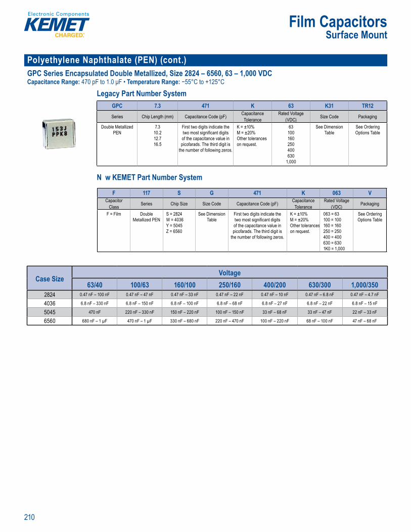
210
Film Capacitors
Polyethylene Naphthalate (PEN) (cont.)GPC Series Encapsulated Double Metallized, Size 2824 – 6560, 63 – 1,000 VDCCapacitance Range: 470 pF to 1.0 μF • Temperature Range: −55°C to +125°C
Legacy Part Number System
Cl m tic categ ry: 55 125/ 6 t r
• Op rating tem erature range o 55 C to +125 C
Lega art Number System
GPC 7.3 471 K 63 K31 TR12
Series Chip Length (mm) Capacitance Code (pF) CapacitanceTolerance
Rated Voltage(VDC) Size Code Packaging
Double Metallized PEN
7.310.212.716.5
First two digits indicate the two most signifi cant digits of the capacitance value in picofarads. The third digit is
the number of following zeros.
K = ±10% M = ±20%Other tolerances on request.
63100160250400630
1,000
See Dimension Table
See Ordering Options Table
N w KEMET Part Number System
C imat c cate ry: 55 125 6 t r i
• Ope ating tem erature range -55 C o +125 C
L g a Nu e y
GP 7 3 471 K 63 K31 TR1
Ser es Ch p Length (mm) Capacitance Code (pF) CapacitanceToleran e
Rated Vo tage(VDC) Size Code Packag ng
Double Meta lized PEN
7.10 212 716 5
First two digits indi ate the two m st s gn fi cant digits of the apa itan e value in pico arads The third digit is
the number f fo l wing zer s
K = ±10% M = ±20%Other t leran es on request
63100160250400630
1,000
See Dimension Table
See O de ing Options Tab e
New KEME Part Number System
F 117 S G 471 K 063 VCapacitor
Class Series Chip Size Size Code Capacitance Code (pF) CapacitanceTolerance
Rated Voltage (VDC) Packaging
F = Film Double Metallized PEN
S = 2824W = 4036Y = 5045Z = 6560
See Dimension Table
First two digits indicate the two most signifi cant digits of the capacitance value in picofarads. The third digit is
the number of following zeros.
K = ±10% M = ±20%Other tolerances on request.
063 = 63100 = 100160 = 160250 = 250400 = 400630 = 6301K0 = 1,000
See Ordering Options Table
Case SizeVoltage
63/40 100/63 160/100 250/160 400/200 630/300 1,000/3502824 0.47 nF – 100 nF 0.47 nF – 47 nF 0.47 nF – 33 nF 0.47 nF – 22 nF 0.47 nF – 10 nF 0.47 nF – 6.8 nF 0.47 nF – 4.7 nF
4036 6.8 nF – 330 nF 6.8 nF – 150 nF 6.8 nF – 100 nF 6.8 nF – 68 nF 6.8 nF – 27 nF 6.8 nF – 22 nF 6.8 nF – 15 nF
5045 470 nF 220 nF – 330 nF 150 nF – 220 nF 100 nF – 150 nF 33 nF – 68 nF 33 nF – 47 nF 22 nF – 33 nF
6560 680 nF – 1 µF 470 nF – 1 µF 330 nF – 680 nF 220 nF – 470 nF 100 nF – 220 nF 68 nF – 100 nF 47 nF – 68 nF
Surface Mount
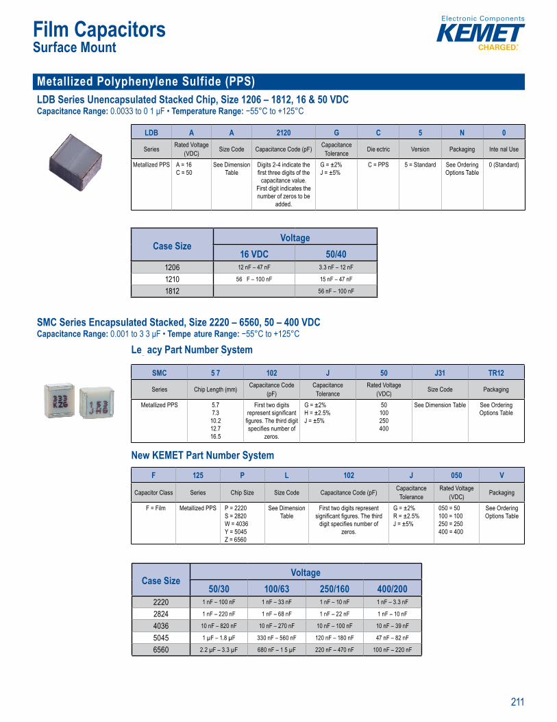
211
Film Capacitors
Metallized Polyphenylene Sulfide (PPS) LDB Series Unencapsulated Stacked Chip, Size 1206 – 1812, 16 & 50 VDCCapacitance Range: 0.0033 to 0 1 μF • Temperature Range: −55°C to +125°C
Opera ing
a t um er System
LDB A A 2120 G C 5 N 0
Series Rated Voltage (VDC) Size Code Capacitance Code (pF) Capacitance
Tolerance Die ectric Version Packaging Inte nal Use
Metallized PPS A = 16C = 50
See Dimension Table
Digits 2-4 indicate the fi rst three digits of the
capacitance value. First digit indicates the number of zeros to be
added.
G = ±2% J = ±5%
C = PPS 5 = Standard See Ordering Options Table
0 (Standard)
Case SizeVoltage
16 VDC 50/401206 12 nF – 47 nF 3.3 nF – 12 nF
1210 56 F – 100 nF 15 nF – 47 nF
1812 56 nF – 100 nF
SMC Series Encapsulated Stacked, Size 2220 – 6560, 50 – 400 VDCCapacitance Range: 0.001 to 3 3 μF • Tempe ature Range: −55°C to +125°C
Le acy Part Number System
ize: 22 0 – 6 5 ateg mp ia m na i ns tem
Overview
hen i urfac
eq ire f L 0 SMC c citors mee the a s c g 8
T ti an
ature N ble for s-the-line cation (se s p c i
SMC Seri s Encapsulate
Legacy Part Number System
SMC 5 7 102 J 50 J31 TR12
Series Chip Length (mm) Capacitance Code (pF)
CapacitanceTolerance
Rated Voltage(VDC) Size Code Packaging
Metallized PPS 5.77.3
10.212.716.5
First two digits represent signifi cant
fi gures. The third digit specifi es number of
zeros.
G = ±2%H = ±2.5%J = ±5%
50100250400
See Dimension Table See Ordering Options Table
New KEMET Part Number System
citance tolera mp i m na i n t
Overview
Pol ny s l hi e (PPS lm c to fo s c
eq ir U M eet t d ording to IEC 3 2 .
App
an re e e- o sup re c p
Legacy Part Number System
er es ngt anc i d V ze Co ck gin
llized P 5.7
102
16 5
o t
res The third d specifi es number of
eros
2 2 %
J ±5% 5400
imen ion ee Orderin
New KEME Part Number System
F 125 P L 102 J 050 V
Capacitor Class Series Chip Size Size Code Capacitance Code (pF) CapacitanceTolerance
Rated Voltage (VDC) Packaging
F = Film Metallized PPS P = 2220S = 2820W = 4036Y = 5045Z = 6560
See Dimension Table
First two digits represent signifi cant fi gures. The third
digit specifi es number of zeros.
G = ±2%R = ±2.5%J = ±5%
050 = 50100 = 100250 = 250400 = 400
See Ordering Options Table
Case SizeVoltage
50/30 100/63 250/160 400/2002220 1 nF – 100 nF 1 nF – 33 nF 1 nF – 10 nF 1 nF – 3.3 nF
2824 1 nF – 220 nF 1 nF – 68 nF 1 nF – 22 nF 1 nF – 10 nF
4036 10 nF – 820 nF 10 nF – 270 nF 10 nF – 100 nF 10 nF – 39 nF
5045 1 µF – 1.8 µF 330 nF – 560 nF 120 nF – 180 nF 47 nF – 82 nF
6560 2.2 µF – 3.3 µF 680 nF – 1 5 µF 220 nF – 470 nF 100 nF – 220 nF
Surface Mount
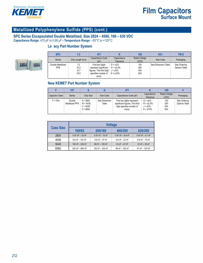
212
Film Capacitors
Metallized Polyphenylene Sulfide (PPS) (cont.) SPC Series Encapsulated Double Metallized, Size 2824 – 6560, 100 – 630 VDCCapacitance Range: 470 pF to 0.68 μF • Temperature Range: −55°C to +125°C
Le acy Part Number System
Legacy Part Number System
SPC 7.3 471 K 100 K31 TR12Series Chip Length (mm) Capacitance Code
(pF)Capacitance
ToleranceRated Voltage
(VDC) Size Code Packaging
Double Metallized PPS
7.310.212.716.5
First two digits represent signifi cant
fi gures. The third digit specifi es number of
zeros.
G = ±2%H = ±2.5%J = ±5%K = ±10%
100250400630
See Dimension Table See Ordering Options Table
New KEME Part Number System
F 127 S G 471 K 100 V
Capacitor Class Series Chip Size Size Code Capacitance Code (pF) CapacitanceTolerance
Rated Voltage (VDC) Packaging
F = Film Double Metallized PPS
S = 2824W = 4036Y = 5045
See Dimension Table
First two digits represent signifi cant fi gures. The third
digit specifi es number of
G = ±2%R = ±2.5%J = ±5%
100250400
See Ordering Options Table
New KEMET Part Number System
Legacy Part Number System
SPC 7.3 471 K 100 K31 TR12Series Chip Length (mm) Capacitance Code
(pF)Capacitance
ToleranceRated Voltage
(VDC) Size Code Packaging
Double Metallized PPS
7.310.212.716.5
First two digits represent signifi cant
fi gures. The third digit specifi es number of
zeros.
G = ±2%H = ±2.5%J = ±5%K = ±10%
100250400630
See Dimension Table See Ordering Options Table
New KEME Part Number System
F 127 S G 471 K 100 V
Capacitor Class Series Chip Size Size Code Capacitance Code (pF) CapacitanceTolerance
Rated Voltage (VDC) Packaging
F = Film Double Metallized PPS
S = 2824W = 4036Y = 5045Z = 6560
See Dimension Table
First two digits represent signifi cant fi gures. The third
digit specifi es number of zeros.
G = ±2%R = ±2.5%J = ±5%K = ±10%
100250400630
See Ordering Options Table
Case SizeVoltage
100/63 250/160 400/250 630/3502824 0.47 nF – 33 nF 0.47 nF – 15 nF 0.47 nF – 6.8 nF 0.47 nF – 4.7 nF
4036 6.8 nF – 100 nF 6.8 nF – 47 nF 6.8 nF – 22 nF 6.8 nF – 15 nF
5045 150 nF – 220 nF 68 nF – 100 nF 33 nF – 47 nF 22 nF – 33 nF
6560 330 nF – 680 nF 150 nF – 330 nF 68 nF – 150 nF 47 nF – 100 nF
Surface Mount
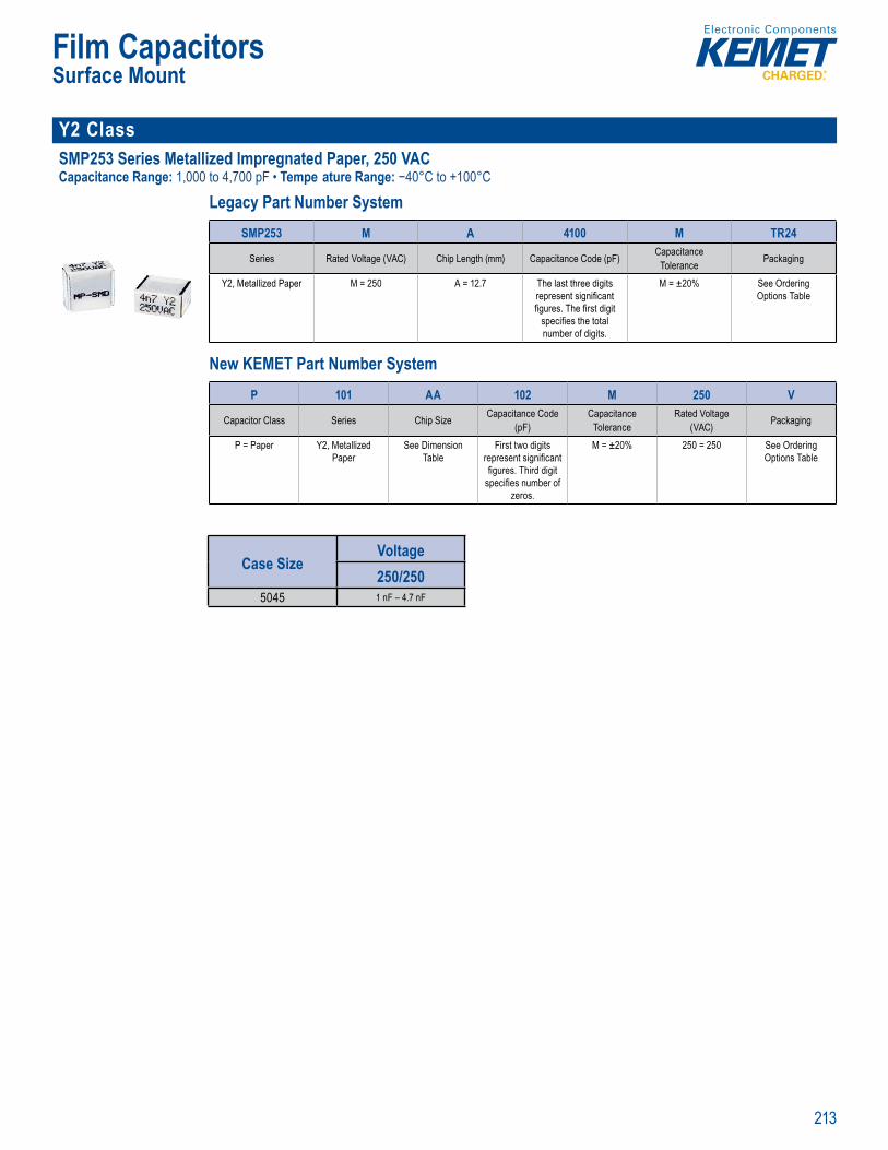
213
Film Capacitors
Y2 ClassSMP253 Series Metallized Impregnated Paper, 250 VAC Capacitance Range: 1,000 to 4,700 pF • Tempe ature Range: −40°C to +100°C
Legacy Part Number System
Capa itan gh s t re active and
bi i
Legacy Part Number System
SMP253 M A 4100 M TR24
Series Rated Voltage (VAC) Chip Length (mm) Capacitance Code (pF) CapacitanceTolerance Packaging
Y2, Metallized Paper M = 250 A = 12.7 The last three digits represent signifi cant fi gures. The fi rst digit
specifi es the total number of digits.
M = ±20% See Ordering Options Table
New KEMET Part Number System
Clima c c
Legac P rt Number System
S es t ng nce C cita ka i
allized = 250 A = 12 T e last th e di its
g r s Th fi r t digit s ifi th t l
b di i
M = ±20 e Orderin
New KEME art Number System
P 101 AA 102 M 250 V
Capacitor Class Series Chip Size Capacitance Code (pF)
CapacitanceTolerance
Rated Voltage(VAC) Packaging
P = Paper Y2, Metallized Paper
See Dimension Table
First two digits represent signifi cant fi gures. Third digit
specifi es number of zeros.
M = ±20% 250 = 250 See Ordering Options Table
Case SizeVoltage250/250
5045 1 nF – 4.7 nF
Surface Mount
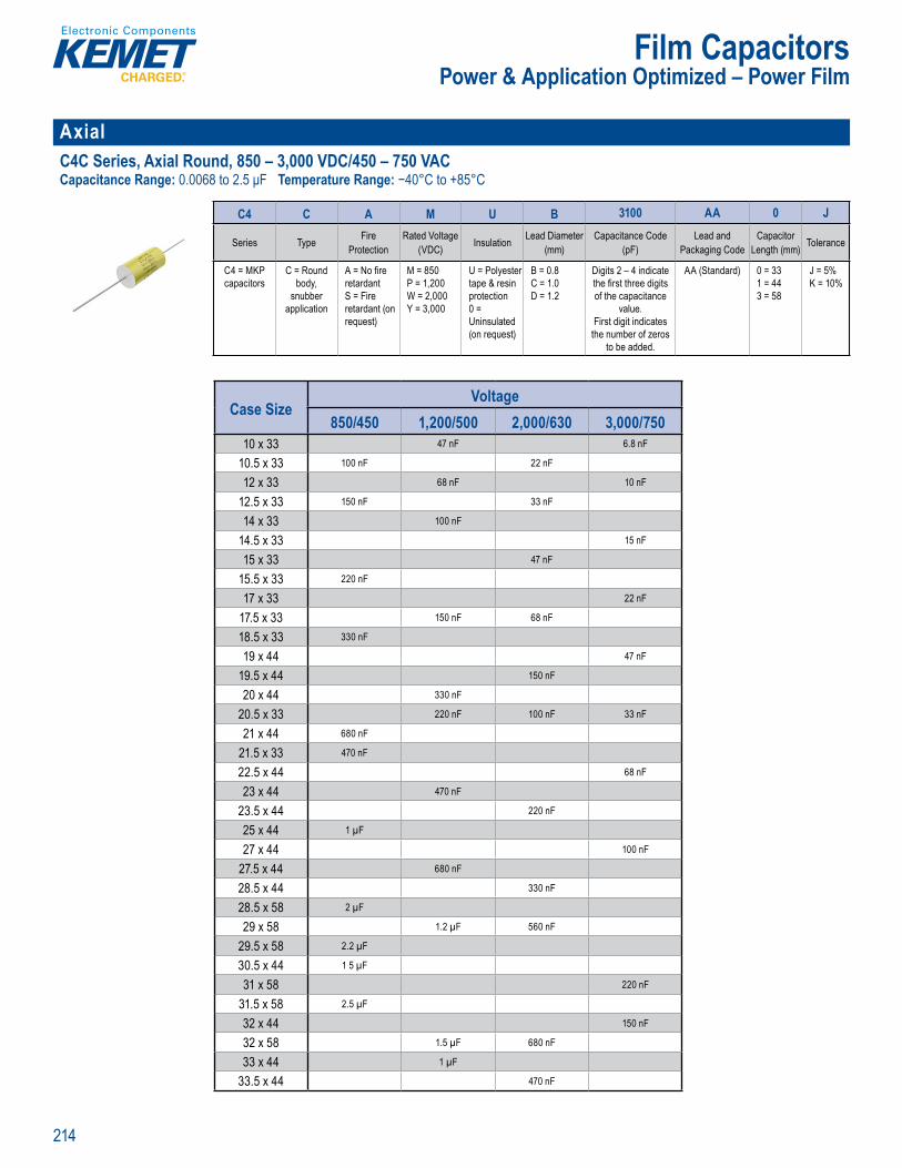
214
Film Capacitors
Axial C4C Series, Axial Round, 850 – 3,000 VDC/450 – 750 VACCapacitance Range: 0.0068 to 2.5 μF Temperature Range: −40°C to +85°C
Pa t Num er System
C4 C A M U B 3100 AA 0 J
Series Type Fire Protection
Rated Voltage (VDC) Insulation Lead Diameter
(mm)Capacitance Code
(pF)Lead and
Packaging CodeCapacitor
Length (mm) Tolerance
C4 = MKP capacitors
C = Round body,
snubber application
A = No fi re retardantS = Fire retardant (on request)
M = 850P = 1,200W = 2,000Y = 3,000
U = Polyester tape & resin protection0 = Uninsulated (on request)
B = 0.8C = 1.0D = 1.2
Digits 2 – 4 indicate the fi rst three digits of the capacitance
value. First digit indicates
the number of zeros to be added.
AA (Standard) 0 = 331 = 443 = 58
J = 5%K = 10%
Case SizeVoltage
850/450 1,200/500 2,000/630 3,000/75010 x 33 47 nF 6.8 nF
10.5 x 33 100 nF 22 nF
12 x 33 68 nF 10 nF
12.5 x 33 150 nF 33 nF
14 x 33 100 nF
14.5 x 33 15 nF
15 x 33 47 nF
15.5 x 33 220 nF
17 x 33 22 nF
17.5 x 33 150 nF 68 nF
18.5 x 33 330 nF
19 x 44 47 nF
19.5 x 44 150 nF
20 x 44 330 nF
20.5 x 33 220 nF 100 nF 33 nF
21 x 44 680 nF
21.5 x 33 470 nF
22.5 x 44 68 nF
23 x 44 470 nF
23.5 x 44 220 nF
25 x 44 1 µF
27 x 44 100 nF
27.5 x 44 680 nF
28.5 x 44 330 nF
28.5 x 58 2 µF
29 x 58 1.2 µF 560 nF
29.5 x 58 2.2 µF
30.5 x 44 1 5 µF
31 x 58 220 nF
31.5 x 58 2.5 µF
32 x 44 150 nF
32 x 58 1.5 µF 680 nF
33 x 44 1 µF
33.5 x 44 470 nF
Power & Application Optimized – Power Film
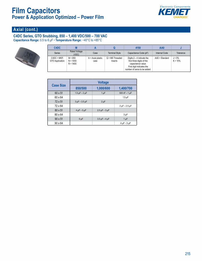
215
Film Capacitors
Axial (cont.)C4DC Series, GTO Snubbing, 850 – 1,400 VDC/500 – 700 VAC Capacitance Range: 0.5 to 6 μF • Temperature Range: −40°C to +85°C
Par Number System
C4DC M A Q 4150 AA0 JSeries Rated Voltage
(VDC) Case Terminal Style Capacitance Code (pF) Internal Code Tolerance
C4DC = MKP, GTO Application
M = 850N = 1000R = 1400
A = Axial plastic case
Q = M8 Threaded Inserts
Digits 2 – 4 indicate the fi rst three digits of the
capacitance value. First digit indicates the
number of zeros to be added.
AA0 = Standard J = 5%K = 10%
Case SizeVoltage
850/500 1,000/600 1,400/70060 x 51 1.5 µF – 2 µF 1 µF 500 nF – 1 µF
60 x 64 1.5 µF
72 x 51 3 µF – 3.5 µF 2 µF
72 x 64 2 µF – 2.5 µF
80 x 51 4 µF – 5 µF 2.5 µF – 3 µF
80 x 64 3 µF
90 x 51 6 µF 3.5 µF – 4 µF 1 µF
90 x 64 4 µF – 5 µF
Power & Application Optimized – Power Film
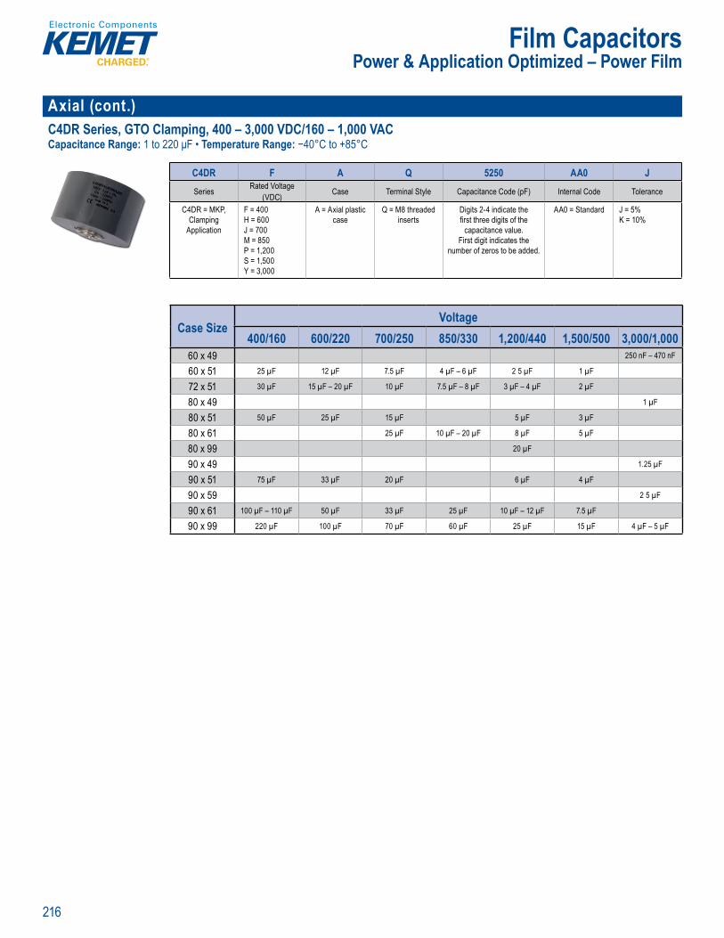
216
Film Capacitors
Axial (cont.)C4DR Series, GTO Clamping, 400 – 3,000 VDC/160 – 1,000 VAC Capacitance Range: 1 to 220 μF • Temperature Range: −40°C to +85°C
Part umber System
C4DR F A Q 5250 AA0 JSeries Rated Voltage
(VDC) Case Terminal Style Capacitance Code (pF) Internal Code Tolerance
C4DR = MKP, Clamping
Application
F = 400H = 600J = 700M = 850P = 1,200S = 1,500Y = 3,000
A = Axial plastic case
Q = M8 threaded inserts
Digits 2-4 indicate the fi rst three digits of the
capacitance value. First digit indicates the
number of zeros to be added.
AA0 = Standard J = 5%K = 10%
Case SizeVoltage
400/160 600/220 700/250 850/330 1,200/440 1,500/500 3,000/1,00060 x 49 250 nF – 470 nF
60 x 51 25 µF 12 µF 7.5 µF 4 µF – 6 µF 2 5 µF 1 µF
72 x 51 30 µF 15 µF – 20 µF 10 µF 7.5 µF – 8 µF 3 µF – 4 µF 2 µF
80 x 49 1 µF
80 x 51 50 µF 25 µF 15 µF 5 µF 3 µF
80 x 61 25 µF 10 µF – 20 µF 8 µF 5 µF
80 x 99 20 µF
90 x 49 1.25 µF
90 x 51 75 µF 33 µF 20 µF 6 µF 4 µF
90 x 59 2 5 µF
90 x 61 100 µF – 110 µF 50 µF 33 µF 25 µF 10 µF – 12 µF 7.5 µF
90 x 99 220 µF 100 µF 70 µF 60 µF 25 µF 15 µF 4 µF – 5 µF
Power & Application Optimized – Power Film
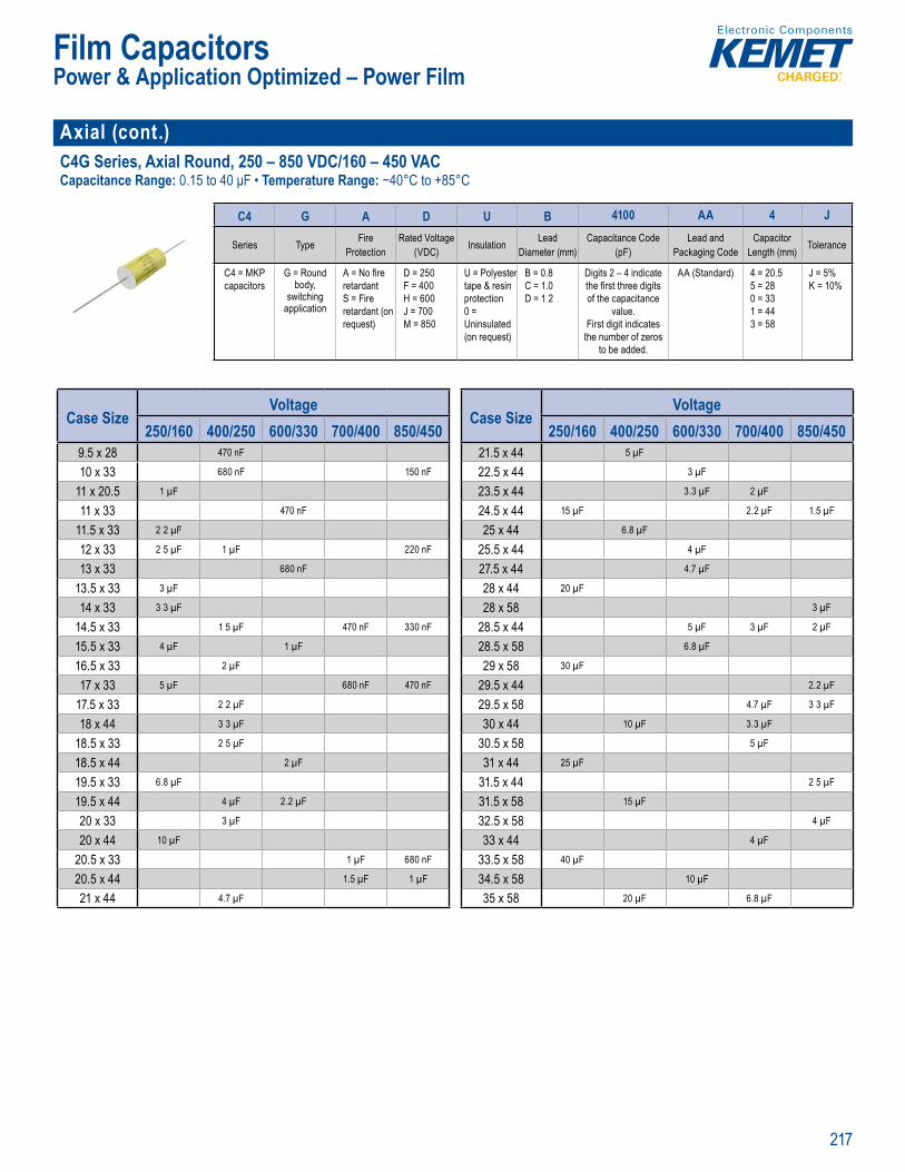
217
Film Capacitors
Axial (cont.)C4G Series, Axial Round, 250 – 850 VDC/160 – 450 VACCapacitance Range: 0.15 to 40 μF • Temperature Range: −40°C to +85°C
Part N mber System
C4 G A D U B 4100 AA 4 J
Series Type Fire Protection
Rated Voltage (VDC) Insulation Lead
Diameter (mm)Capacitance Code
(pF)Lead and
Packaging CodeCapacitor
Length (mm) Tolerance
C4 = MKP capacitors
G = Round body,
switching application
A = No fi re retardantS = Fire retardant (on request)
D = 250F = 400H = 600J = 700M = 850
U = Polyester tape & resin protection0 = Uninsulated (on request)
B = 0.8C = 1.0D = 1 2
Digits 2 – 4 indicate the fi rst three digits of the capacitance
value. First digit indicates
the number of zeros to be added.
AA (Standard) 4 = 20.55 = 280 = 331 = 443 = 58
J = 5%K = 10%
Case SizeVoltage
250/160 400/250 600/330 700/400 850/4509.5 x 28 470 nF
10 x 33 680 nF 150 nF
11 x 20.5 1 µF
11 x 33 470 nF
11.5 x 33 2 2 µF
12 x 33 2 5 µF 1 µF 220 nF
13 x 33 680 nF
13.5 x 33 3 µF
14 x 33 3 3 µF
14.5 x 33 1 5 µF 470 nF 330 nF
15.5 x 33 4 µF 1 µF
16.5 x 33 2 µF
17 x 33 5 µF 680 nF 470 nF
17.5 x 33 2 2 µF
18 x 44 3 3 µF
18.5 x 33 2 5 µF
18.5 x 44 2 µF
19.5 x 33 6.8 µF
19.5 x 44 4 µF 2.2 µF
20 x 33 3 µF
20 x 44 10 µF
20.5 x 33 1 µF 680 nF
20.5 x 44 1.5 µF 1 µF
21 x 44 4.7 µF
Case SizeVoltage
250/160 400/250 600/330 700/400 850/45021.5 x 44 5 µF
22.5 x 44 3 µF
23.5 x 44 3.3 µF 2 µF
24.5 x 44 15 µF 2.2 µF 1.5 µF
25 x 44 6.8 µF
25.5 x 44 4 µF
27.5 x 44 4.7 µF
28 x 44 20 µF
28 x 58 3 µF
28.5 x 44 5 µF 3 µF 2 µF
28.5 x 58 6.8 µF
29 x 58 30 µF
29.5 x 44 2.2 µF
29.5 x 58 4.7 µF 3 3 µF
30 x 44 10 µF 3.3 µF
30.5 x 58 5 µF
31 x 44 25 µF
31.5 x 44 2 5 µF
31.5 x 58 15 µF
32.5 x 58 4 µF
33 x 44 4 µF
33.5 x 58 40 µF
34.5 x 58 10 µF
35 x 58 20 µF 6.8 µF
Power & Application Optimized – Power Film
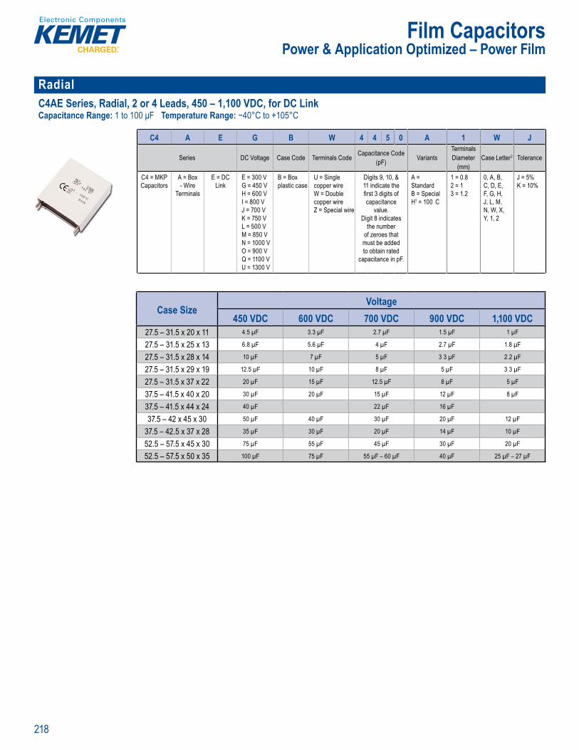
218
Film Capacitors
Radial C4AE Series, Radial, 2 or 4 Leads, 450 – 1,100 VDC, for DC LinkCapacitance Range: 1 to 100 μF Temperature Range: −40°C to +105°C
Part Number System
C4 A E G B W 4 4 5 0 A 1 W J
Series DC Voltage Case Code Terminals Code Capacitance Code (pF) Variants
Terminals Diameter
(mm)Case Letter2 Tolerance
C4 = MKP Capacitors
A = Box - Wire
Terminals
E = DC Link
E = 300 VG = 450 VH = 600 VI = 800 VJ = 700 VK = 750 VL = 500 VM = 850 VN = 1000 VO = 900 VQ = 1100 VU = 1300 V
B = Box plastic case
U = Single copper wireW = Double copper wireZ = Special wire
Digits 9, 10, & 11 indicate the fi rst 3 digits of capacitance
value.Digit 8 indicates
the number of zeroes that must be added to obtain rated
capacitance in pF.
A = StandardB = SpecialH1 = 100 C
1 = 0.82 = 13 = 1.2
0, A, B,C, D, E,F, G, H,J, L, M,N, W, X,Y, 1, 2
J = 5%K = 10%
Case SizeVoltage
450 VDC 600 VDC 700 VDC 900 VDC 1,100 VDC27.5 – 31.5 x 20 x 11 4.5 µF 3.3 µF 2.7 µF 1.5 µF 1 µF
27.5 – 31.5 x 25 x 13 6.8 µF 5.6 µF 4 µF 2.7 µF 1.8 µF
27.5 – 31.5 x 28 x 14 10 µF 7 µF 5 µF 3 3 µF 2.2 µF
27.5 – 31.5 x 29 x 19 12.5 µF 10 µF 8 µF 5 µF 3 3 µF
27.5 – 31.5 x 37 x 22 20 µF 15 µF 12.5 µF 8 µF 5 µF
37.5 – 41.5 x 40 x 20 30 µF 20 µF 15 µF 12 µF 8 µF
37.5 – 41.5 x 44 x 24 40 µF 22 µF 16 µF
37.5 – 42 x 45 x 30 50 µF 40 µF 30 µF 20 µF 12 µF
37.5 – 42.5 x 37 x 28 35 µF 30 µF 20 µF 14 µF 10 µF
52.5 – 57.5 x 45 x 30 75 µF 55 µF 45 µF 30 µF 20 µF
52.5 – 57.5 x 50 x 35 100 µF 75 µF 55 µF – 60 µF 40 µF 25 µF – 27 µF
Power & Application Optimized – Power Film
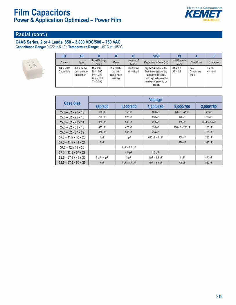
219
Film Capacitors
Radial (cont.)C4AS Series, 2 or 4 Leads, 850 – 3,000 VDC/500 – 750 VACCapacitance Range: 0.022 to 5 μF • Temperature Range: −40°C to +85°C
Part N mber System
C4 AS M B U 3150 A3 A JSeries Type Rated Voltage
(VDC) Case Number of Leads Capacitance Code (pF) Lead Diameter
(mm) Size Code Tolerance
C4 = MKP Capacitors
AS = Radial box, snubber application
M = 850N = 1,000P = 1,200W = 2,000Y = 3,000
B = Plastic box with
epoxy resin sealing
U = 2 leadW = 4 lead
Digits 2-4 indicate the fi rst three digits of the
capacitance value. First digit indicates the number of zeros to be
added.
A1 = 0.8A3 = 1.2
See Dimension Table
J = 5%K = 10%
Case SizeVoltage
850/500 1,000/600 1,200/630 2,000/700 3,000/75027.5 – 32 x 20 x 10 150 nF 150 nF 100 nF 33 nF – 47 nF 22 nF
27.5 – 32 x 22 x 13 220 nF 220 nF 150 nF 68 nF 33 nF
27.5 – 32 x 28 x 14 330 nF 330 nF 220 nF 100 nF 47 nF – 68 nF
27.5 – 32 x 33 x 18 470 nF 470 nF 330 nF 150 nF – 220 nF 100 nF
27.5 – 32 x 37 x 22 680 nF 680 nF 470 nF 150 nF
37.5 – 41.5 x 40 x 20 1 µF 1 µF 680 nF – 1 µF 330 nF 220 nF
37.5 – 41.5 x 44 x 24 2 µF 680 nF 330 nF
37.5 – 42 x 45 x 30 2 µF – 2.2 µF
37.5 – 42.5 x 37 x 28 1.5 µF 1.2 µF
52.5 – 57.5 x 45 x 30 3 µF – 4 µF 3 µF 2 µF – 2 5 µF 1 µF 470 nF
52.5 – 57.5 x 50 x 35 5 µF 4 µF – 4.7 µF 3 µF – 3 5 µF 1.5 µF 820 nF
Power & Application Optimized – Power Film
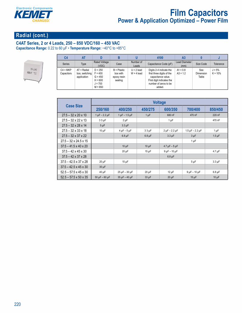
220
Film Capacitors
Radial (cont.)C4AT Series, 2 or 4 Leads, 250 – 850 VDC/160 – 450 VACCapacitance Range: 0.22 to 60 μF • Temperature Range: −40°C to +85°C
Part N mber System
C4 AT D B U 4100 A3 0 JSeries Type Rated Voltage
(VDC) Case Number of Leads Capacitance Code (pF) Lead Diameter
(mm) Size Code Tolerance
C4 = MKP Capacitors
AT = Radial box, switching application
D = 250F = 400G = 450H = 600J = 700M = 850
B = Plastic box with
epoxy resin sealing
U = 2 leadW = 4 lead
Digits 2-4 indicate the fi rst three digits of the
capacitance value. First digit indicates the number of zeros to be
added.
A1 = 0.8A3 = 1.2
See Dimension
Table
J = 5%K = 10%
Case SizeVoltage
250/160 400/250 450/275 600/350 700/400 850/45027.5 – 32 x 20 x 10 1 µF – 2.2 µF 1 µF – 1.5 µF 1 µF 680 nF 470 nF 220 nF
27.5 – 32 x 22 x 13 3 3 µF 2 µF 1 µF 470 nF
27.5 – 32 x 28 x 14 5 µF 3.3 µF
27.5 – 32 x 33 x 18 10 µF 4 µF – 5 µF 3 3 µF 2 µF – 2.2 µF 1.5 µF – 2.2 µF 1 µF
27.5 – 32 x 37 x 22 6.8 µF 6.8 µF 3.3 µF 3 µF 1.5 µF
27.5 – 32 x 24.5 x 15 1 µF
37.5 – 41.5 x 40 x 20 10 µF 10 µF 4.7 µF – 5 µF
37.5 – 42 x 45 x 30 20 µF 15 µF 9 µF – 10 µF 4.7 µF
37.5 – 42 x 37 x 28 6.8 µF
37.5 – 42.5 x 37 x 28 20 µF 15 µF 5 µF 3.3 µF
37.5 – 42.5 x 45 x 30 30 µF
52.5 – 57.5 x 45 x 30 40 µF 25 µF – 30 µF 20 µF 12 µF 9 µF – 10 µF 6.8 µF
52.5 – 57.5 x 50 x 35 50 µF – 60 µF 35 µF – 40 µF 33 µF 20 µF 15 µF 10 µF
Power & Application Optimized – Power Film
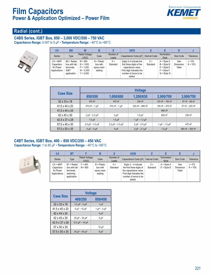
221
Film CapacitorsPower & Application Optimized – Power Film
Radial (cont.)C4BS Series, IGBT Box, 850 – 3,000 VDC/550 – 750 VAC Capacitance Range: 0.047 to 5 μF • Temperature Range: −40°C to +85°C
Par N mber System
C4 BS M B X 3470 Z E E JSeries Type Rated Voltage
(VDC) Case Number of Leads Capacitance Code (pF) Internal Code Termination
Style Size Code Tolerance
C4 = MKP Capacitorsfor Power
Applications
BS = Radial box with tab terminals, IGBT application
M = 850N = 1,000P = 1,200W = 2,000Y = 3,000
B = Plastic box with
epoxy resin sealing
X = Standard
Digits 2-4 indicate the fi rst three digits of the
capacitance value. First digit indicates the number of zeros to be
added.
Z = Standard
A = Style AB = Style BE = Style EF = Style FG = Style G
See Dimension
Table
J = 5%K = 10%
Case SizeVoltage
850/550 1,000/600 1,200/630 2,000/700 3,000/75032 x 33 x 18 470 nF 470 nF 330 nF 100 nF – 150 nF 47 nF – 68 nF
41.5 x 40 x 20 470 nF – 1 µF 470 nF – 1 µF 330 nF – 680 nF 100 nF – 470 nF 47 nF – 220 nF
41.5 x 44 x 24 680 nF
42 x 45 x 30 2 µF – 2.2 µF 2 µF 1.5 µF 820 nF 330 nF
42.5 x 37 x 28 1.5 µF 1.5 µF 1 µF – 1 2 µF
57.5 x 45 x 30 2.5 µF – 3.3 µF 2.2 µF – 3.3 µF 2 µF – 2 5 µF 1 µF – 1.2 µF 470 nF
57.5 x 50 x 35 4 µF – 5 µF 4 µF 3 µF – 3 3 µF 1.5 µF 680 nF – 820 nF C4BT Series, IGBT Box, 400 – 850 VDC/250 – 450 VACCapacitance Range: 1 to 60 μF • Temperature Range: −40°C to +85°C
Par Number System
C4 BT F B X 4330 Z E E JSeries Type Rated Voltage
(VDC) Case Number of Leads Capacitance Code (pF) Internal Code Termination
Style Size Code Tolerance
C4 = MKP Capacitors for Power
Applications
BT = Radial box with tab terminals, switching application
F = 400M = 850
B = Plastic box with
epoxy resin sealing
X = Standard
Digits 2 – 4 indicate the fi rst three digits of the capacitance value. First digit indicates the number of zeros to be
added.
Z = Standard
A = Style AE = Style E
See Dimension
Table
J = 5%K = 10%
Case SizeVoltage
400/250 850/45032 x 33 x 18 3.3 µF – 5 µF 1 µF
41.5 x 40 x 20 4 µF – 10 µF 1 µF – 3 µF
42 x 44 x 24 4 µF
42 x 45 x 30 20 µF – 30 µF 5 µF
42.5 x 37 x 28 12.5 µF – 15 µF
57 x 50 x 35 10 µF
57.5 x 50 x 35 35 µF – 40 µF 8 µF
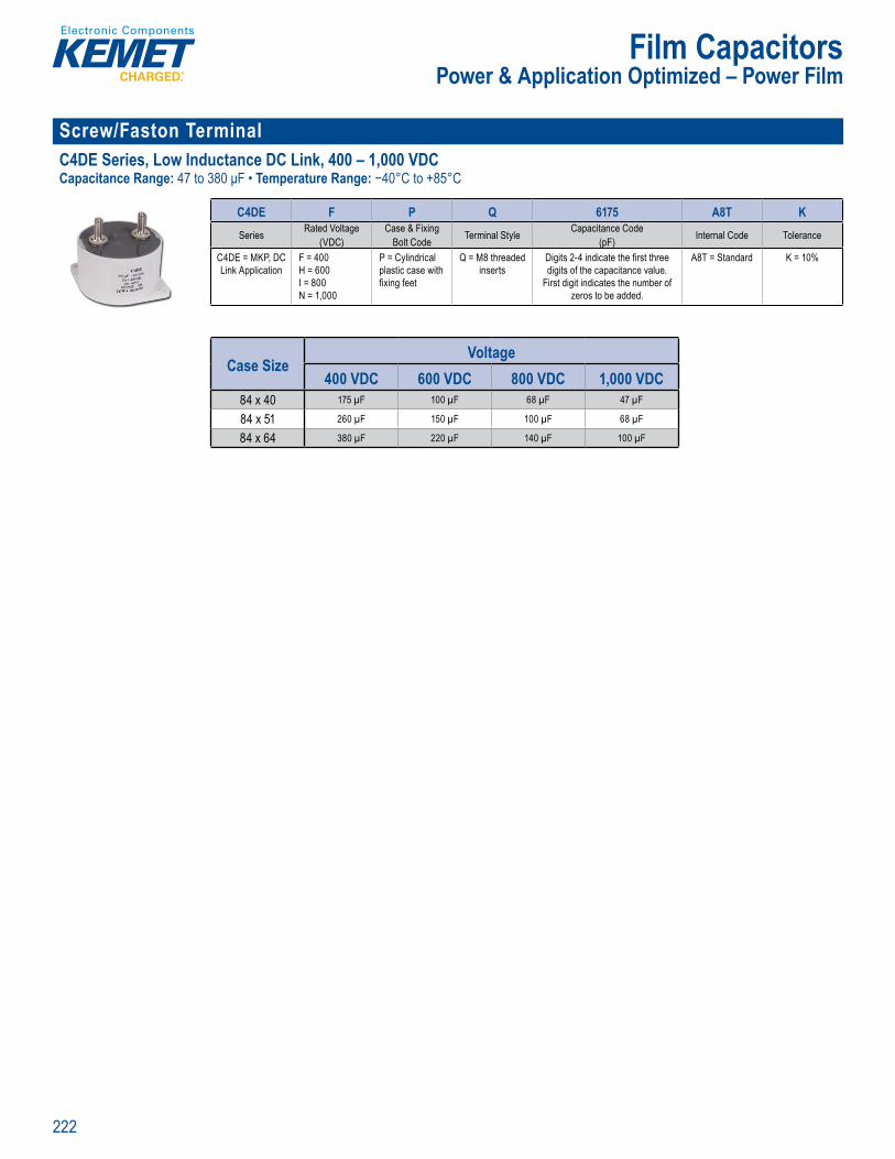
222
Film CapacitorsPower & Application Optimized – Power Film
Screw/Faston Terminal C4DE Series, Low Inductance DC Link, 400 – 1,000 VDCCapacitance Range: 47 to 380 μF • Temperature Range: −40°C to +85°C
Pa N mber System
C4DE F P Q 6175 A8T KSeries Rated Voltage
(VDC)Case & Fixing
Bolt Code Terminal Style Capacitance Code (pF) Internal Code Tolerance
C4DE = MKP, DC Link Application
F = 400H = 600I = 800N = 1,000
P = Cylindrical plastic case with fi xing feet
Q = M8 threaded inserts
Digits 2-4 indicate the fi rst three digits of the capacitance value.
First digit indicates the number of zeros to be added.
A8T = Standard K = 10%
Case SizeVoltage
400 VDC 600 VDC 800 VDC 1,000 VDC84 x 40 175 µF 100 µF 68 µF 47 µF
84 x 51 260 µF 150 µF 100 µF 68 µF
84 x 64 380 µF 220 µF 140 µF 100 µF
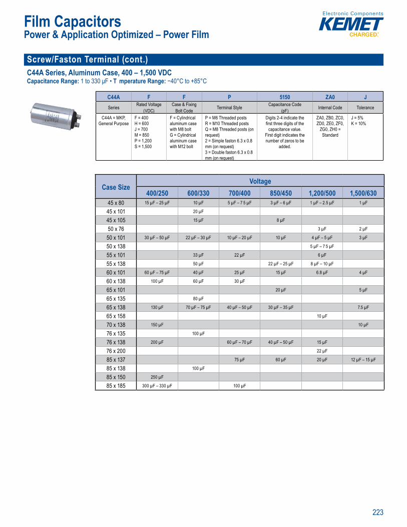
223
Film CapacitorsPower & Application Optimized – Power Film
Screw/Faston Terminal (cont.)C44A Series, Aluminum Case, 400 – 1,500 VDCCapacitance Range: 1 to 330 μF • T mperature Range: −40°C to +85°C
Part umbe System
C44A F F P 5150 ZA0 JSeries Rated Voltage
(VDC)Case & Fixing
Bolt Code Terminal Style Capacitance Code (pF) Internal Code Tolerance
C44A = MKP, General Purpose
F = 400H = 600J = 700M = 850P = 1,200S = 1,500
F = Cylindrical aluminum case with M8 boltG = Cylindrical aluminum case with M12 bolt
P = M6 Threaded postsR = M10 Threaded postsQ = M8 Threaded posts (on request)2 = Simple faston 6.3 x 0.8 mm (on request)3 = Double faston 6.3 x 0.8 mm (on request)
Digits 2-4 indicate the fi rst three digits of the
capacitance value. First digit indicates the number of zeros to be
added.
ZA0, ZB0, ZC0, ZD0, ZE0, ZF0,
ZG0, ZH0 = Standard
J = 5%K = 10%
Case SizeVoltage
400/250 600/330 700/400 850/450 1,200/500 1,500/63045 x 80 15 µF – 25 µF 10 µF 5 µF – 7 5 µF 3 µF – 6 µF 1 µF – 2.5 µF 1 µF
45 x 101 20 µF
45 x 105 15 µF 8 µF
50 x 76 3 µF 2 µF
50 x 101 30 µF – 50 µF 22 µF – 30 µF 10 µF – 20 µF 10 µF 4 µF – 5 µF 3 µF
50 x 138 5 µF – 7 5 µF
55 x 101 33 µF 22 µF 6 µF
55 x 138 50 µF 22 µF – 25 µF 8 µF – 10 µF
60 x 101 60 µF – 75 µF 40 µF 25 µF 15 µF 6.8 µF 4 µF
60 x 138 100 µF 60 µF 30 µF
65 x 101 20 µF 5 µF
65 x 135 80 µF
65 x 138 130 µF 70 µF – 75 µF 40 µF – 50 µF 30 µF – 35 µF 7.5 µF
65 x 158 10 µF
70 x 138 150 µF 10 µF
76 x 135 100 µF
76 x 138 200 µF 60 µF – 70 µF 40 µF – 50 µF 15 µF
76 x 200 22 µF
85 x 137 75 µF 60 µF 20 µF 12 µF – 15 µF
85 x 138 100 µF
85 x 150 250 µF
85 x 185 300 µF – 330 µF 100 µF
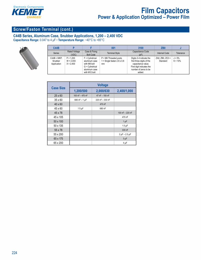
224
Film CapacitorsPower & Application Optimized – Power Film
Screw/Faston Terminal (cont.)C44B Series, Aluminum Case, Snubber Applications, 1,200 – 2,400 VDCCapacitance Range: 0.047 to 4 μF • Temperature Range: −40°C to +85°C
Part N mber System
C44B P F 001 3100 ZB0 JSeries Rated Voltage
(VDC)Case & Fixing
Bolt Code Terminal Style Capacitance Code (pF) Internal Code Tolerance
C44B = MKP, Snubber
Application
P = 1,200W = 2,000X = 2,400
F = Cylindrical aluminum case with M8 boltG = Cylindrical aluminum case with M12 bolt
P = M6 Threaded posts1 = Single fasten 2.8 x 0.8 mm
Digits 2-4 indicate the fi rst three digits of the
capacitance value. First digit indicates the number of zeros to be
added.
ZA0, ZB0, ZC0 = Standard
J = 5%K = 10%
Case SizeVoltage
1,200/500 2,000/630 2,400/1,00025 x 60 100 nF – 470 nF 47 nF – 150 nF
35 x 60 680 nF – 1 µF 220 nF – 330 nF
40 x 60 470 nF
45 x 60 1 5 µF 680 nF
45 x 78 100 nF – 220 nF
45 x 105 470 nF
50 x 100 1 µF
50 x 135 1.5 µF
55 x 78 330 nF
55 x 200 2 µF – 2.5 µF
65 x 175 3 µF
65 x 200 4 µF

225
Film Capacitors
Screw/Faston Terminal (cont.)C44H Series, 330 – 440 VAC, 700 – 1,000 VDC, for PFC and AC FilterCapacitance Range: 100 to 600 µF • Temperature Range: −40°C to +75°C
Pa t umber System
C44H L G P 6100 A A S J
Series Rated Voltage Case & Fixing Bolt Code Terminal Style Capacitance Code (pF) Internal Code Internal Code Tolerance
C44H = MKP Capacitors for
AC fi ltering
L = 330 VrmsK = 440 Vrms
G = Cylindrical aluminum case with M12 bolt
P = M6 Threaded PostsR = M10 Threaded Posts
Digits 9-11 indicate the fi rst three digits of the
capacitance value. Digit 8 indicates the number
of zeros to be added.
A = StandardZ = Special
J = 5%K = 10%
Case SizeVoltage
700/330 1,000/44065 x 98 100 µF
75 x 117 200 µF
75 x 142 100 µF
75 x 194 300 µF 133 µF – 150 µF
75 x 242 400 µF – 500 µF 200 µF
85 x 142 133 µF
85 x 242 600 µF 250 µF C44P/C20A Series, for PFC & AC Filter, 330 – 1,000 VAC, 700 – 2,300 VDC Capacitance Range: 10 to 600 μF Temperature Range: −40°C to +80°C
with plastic Long li etime
Overvi w
44 / y d e o ,
insul nd overpres sa et d
ypica u ta w o
r
Pa t N mber System
C 44 P L G R 6 1 0 0 A A S J
Series Application Rated Voltage (VAC) Case Type
Terminal Style Capacitance Code (pF) Internal Code Internal
Codes Tolerance
MKP Capacitors for Power
Applications
44 = 330 – 440 VAC20 = 550 – 1,000 VAC
AC FilterP = C44A = C20
For C44P:L = 330K = 440
For C20A:K = 550L = 640Q = 780Z = 1000
G = M12 bolt
R = Male M10
Digits 9 – 11 indicate the fi rst 3 digits of
capacitance value. Digit 8 indicates the number of zeros that must be added to obtain rated
capacitance in pF.
A = StandardZ = Special
J = 5%K = 10%
C44P
Case SizeVoltage
700/330 1,000/44065 x 115 100 µF
65 x 145 200 µF
65 x 247 300 µF – 400 µF 133 µF – 150 µF
75 x 147 100 µF
75 x 247 500 µF 200 µF
85 x 247 300 µF
85 x 270 600 µF
Power & Application Optimized – Power Film
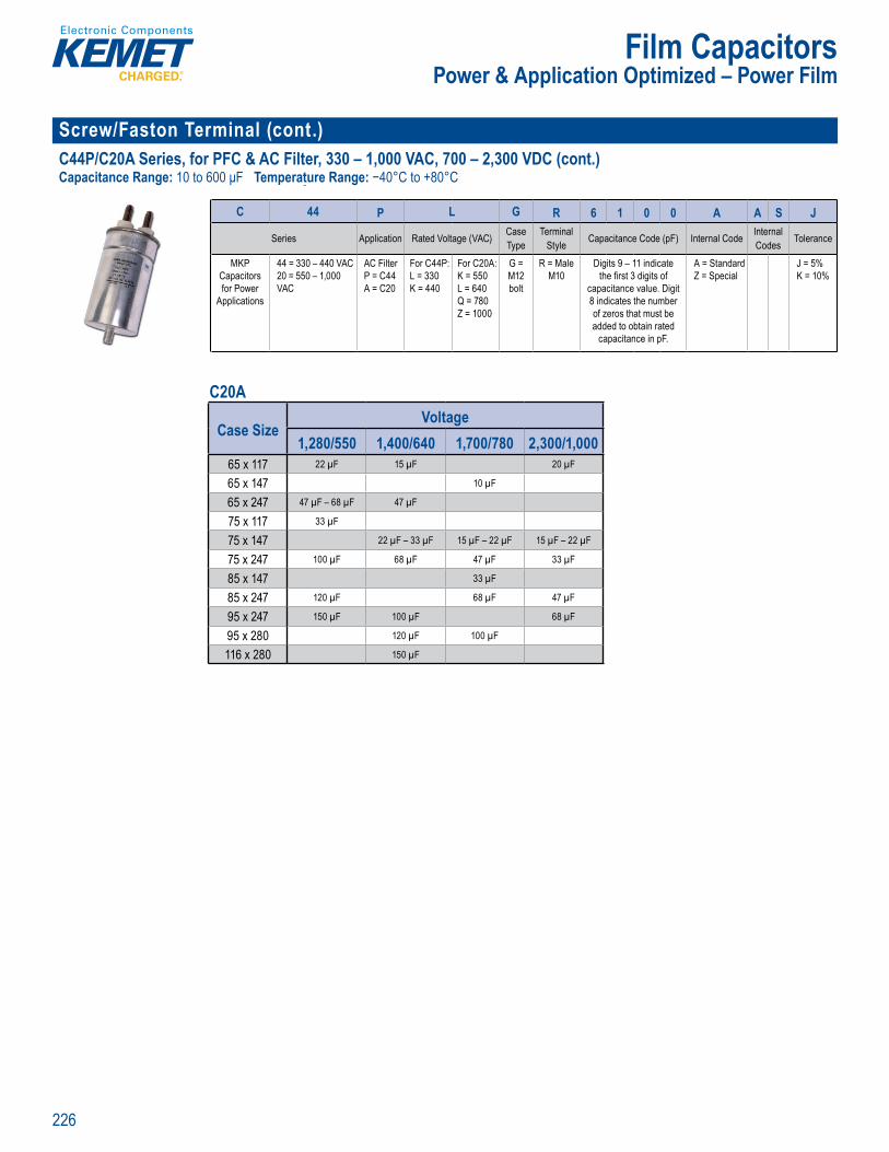
226
Film Capacitors
Screw/Faston Terminal (cont.)C44P/C20A Series, for PFC & AC Filter, 330 – 1,000 VAC, 700 – 2,300 VDC (cont.)Capacitance Range: 10 to 600 μF Temperature Range: −40°C to +80°C
Pa t N mber System
C 44 P L G R 6 1 0 0 A A S J
Series Application Rated Voltage (VAC) Case Type
Terminal Style Capacitance Code (pF) Internal Code Internal
Codes Tolerance
MKP Capacitors for Power
Applications
44 = 330 – 440 VAC20 = 550 – 1,000 VAC
AC FilterP = C44A = C20
For C44P:L = 330K = 440
For C20A:K = 550L = 640Q = 780Z = 1000
G = M12 bolt
R = Male M10
Digits 9 – 11 indicate the fi rst 3 digits of
capacitance value. Digit 8 indicates the number of zeros that must be added to obtain rated
capacitance in pF.
A = StandardZ = Special
J = 5%K = 10%
C20A
Case SizeVoltage
1,280/550 1,400/640 1,700/780 2,300/1,00065 x 117 22 µF 15 µF 20 µF
65 x 147 10 µF
65 x 247 47 µF – 68 µF 47 µF
75 x 117 33 µF
75 x 147 22 µF – 33 µF 15 µF – 22 µF 15 µF – 22 µF
75 x 247 100 µF 68 µF 47 µF 33 µF
85 x 147 33 µF
85 x 247 120 µF 68 µF 47 µF
95 x 247 150 µF 100 µF 68 µF
95 x 280 120 µF 100 µF
116 x 280 150 µF
Power & Application Optimized – Power Film
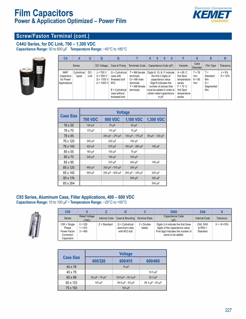
227
Film Capacitors
Screw/Faston Terminal (cont.)C44U Series, for DC Link, 700 – 1,300 VDCCapacitance Range: 50 to 600 μF Temperature Range: −40°C to +85°C
Pa t N mber System
C4 4 U Q G T 6 5 0 0 F 8 S K
Series DC Voltage Case & Fixing Terminals Code Capacitance Code (pF) Variants Case Diameter Film Type Tolerance
MKP Capacitors for Power
Applications
Cylindrical types
DC-Link
J = 700 VO = 900 VQ = 1100 VU = 1300 V
G = Cylindrical case with threaded bolt M12
E = Cylindrical case without threaded bolt
T = M6 female terminalsQ = M8 male terminalsY = M8 female terminals
Digits 9, 10, & 11 indicate the fi rst 3 digits of capacitance value.Digit 8 indicates the
number of zeroes that must be added in order to obtain rated capacitance
in pF.
A = 85 C Hot Spot temperature seriesF = 70 C Hot Spot temperature series
7 = 76 mm8 = 85 mm
T = Standard fi lmS = Segmented fi lm
J = 5%K = 10%
Case SizeVoltage
700 VDC 900 VDC 1,100 VDC 1,300 VDC76 x 55 120 µF 75 µF 50 µF
76 x 70 175 µF 110 µF 75 µF
76 x 95 200 µF – 270 µF 130 µF – 175 µF 90 µF – 120 µF
76 x 120 350 µF 220 µF 150 µF
76 x 140 425 µF 275 µF 190 µF – 280 µF 195 µF
85 x 55 160 µF 100 µF 70 µF
85 x 70 225 µF 150 µF 100 µF
85 x 95 370 µF 240 µF 165 µF
85 x 120 450 µF 300 µF – 510 µF 200 µF
85 x 140 550 µF 350 µF – 600 µF 250 µF – 330 µF 250 µF
85 x 174 500 µF 320 µF
85 x 264 550 µF
C93 Series, Aluminum Case, Filter Applications, 400 – 600 VDCCapacitance Range: 10 to 100 μF • Temperature Range: −25°C to +55°C
A c
C93 S ri s Al 40 – 6 0 VDC
Pa t N mber System
C93 0 Z G 3 5500 ZA0 X Series Rated Voltage
(VAC) Internal Code Case & Mounting Terminal Style Capacitance Code (pF) Internal Code Tolerance
C93 = Single Phase
Power Factor Correction Capacitors
0 = 3201 = 4153 = 460
Z = Standard G = Cylindrical aluminum case with M12 bolt
3 = Double fasten
Digits 2-4 indicate the fi rst three digits of the capacitance value.
First digit indicates the number of zeros to be added.
ZA0, RA0 & RS0 = Standard
X = -5/+15%
Case SizeVoltage
400/320 600/415 600/46040 x 78 10 µF
45 x 78 16 5 µF
60 x 98 50 µF – 70 µF 16.6 µF – 33 3 µF 33 3 µF
60 x 133 100 µF 49.8 µF – 83 µF 66 3 µF – 83 µF
75 x 150 100 µF
Power & Application Optimized – Power Film

228
Film Capacitors
Screw/Faston Terminal (cont.)C9T Series, Aluminum Case, PFC & AC Filter, 415 – 690 VAC Capacitance Range: 19.2 to 184.8 μF • Temperature Range: −25°C to +55°C
Part Num er System
C9T S 5 A D 5308 AA0 XSeries Type Rated Voltage
(VAC) Terminal Style Internal Connection
Capacitance Code (pF) Internal Code Tolerance
C9T = Cylindrical
Three-Phase Capacitors
S = Slim A = 525D = 6905 = 4156 = 450
A = Single quick connectB = Double quick connectM = Screw Terminal
D = DeltaY = Star
Digits 2-4 indicate the fi rst three digits of the capacitance value.
First digit indicates the number of zeros to be added.
AA0 = Standard
X = -5% / +15%
Case SizeVoltage
415 VAC 450 VAC 525 VAC 690 VAC60 x 220 30.8 µF – 46.2 µF 26.2 µF – 39 3 µF 19.2 µF – 29 µF
65 x 220 61.6 µF 52.4 µF 38.5 µF 27.9 µF
75 x 220 77 µF – 92.4 µF 65.5 µF – 78.6 µF 48.1 µF – 57.7 µF
75 x 280 108 µF – 123.2 µF 91.7 µF – 105 µF 67.4 µF – 77 µF 33.4 µF – 39 µF
85 x 280 154 µF 131 µF 96.2 µF 44.6 µF – 55.7 µF
95 x 280 184.8 µF 157 µF 115 µF 66.8 µF
Power & Application Optimized – Power Film

229
Film Capacitors
Screw/Faston Terminal C27 Series, Plastic Case, 250 – 500 VACCapacitance Range: 1 to 100 μF • T mperature Range: −25°C to +100°C
Part umbe System
C27 4 A C 2 4100 AA 4 JSeries Marking Case & Fixing
Bolt Code Terminal Style Capacitance Code (pF) Packaging Internal Use Tolerance
C27 = Motor Run Capacitors
4 = 30,000 hours/420 VAC (Class A) or 10,000 hours/470 VAC (Class B)6 = 10,000 hours/420 VAC (Class B) or 3,000 hours/470 VAC (Class C)7 = 10,000 hours/275 VAC (Class C) or 1,000 hours/425 VAC (Class D)
A = C274C = C276L = C277
C = Cylindrical
plastic case with M8
bolt
2 = Single fasten 6.3 x 0.83 = Double fasten 6 3 x 0.8A = Polar cable (tinned end)B = Polar cable (untinned end)F = Bipolar cable (40 mm unsheathed, 8 mm exposed end)
Digits 2 – 4 indicate the fi rst three digits of
the capacitance value.
First digit indicates the
number of zeros to be added.
AA, AF, AL, LG = Standard
0, 1, 2, 5 = Standard
J = 5%
C274
Case SizeVoltage
470 VAC 500 VAC25 x 55 1 µF – 3 µF
25 x 56.5 1 µF – 2.5 µF
25 x 58 1.25 µF – 3 µF
25 x 58.5 1 µF – 1.5 µF
30 x 55 4 µF – 5 µF
30 x 56.5 2 µF – 5 µF
30 x 57 5 5 µF
30 x 58.5 4 µF
30 x 69.5 6 µF
35 x 55 6 µF
35 x 56.5 6 µF – 8 µF 8 µF
35 x 57 8 µF
35 x 71.5 12 µF
35 x 73.5 9 µF – 12.5 µF
40 x 71.5 16 µF
40 x 73.5 14 µF – 16 µF
45 x 74 18 µF – 20 µF
45 x 93 25 µF – 31.5 µF
45 x 95.5 30 µF
50 x 95 35 µF
50 x 120 40 µF – 50 µF
55 x 120 55 µF
55 x 121 60 µF
Power & Application Optimized – Motor Run Applications
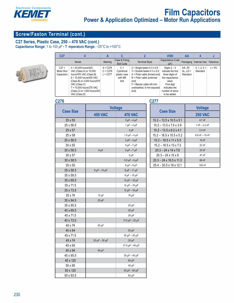
230
Film Capacitors
Screw/Faston Terminal (cont.)C27 Series, Plastic Case, 250 – 470 VAC (cont.)Capacitance Range: 1 to 100 μF • T mperature Range: −25°C to +100°C
Part umbe System
C27 4 A C 2 4100 AA 4 JSeries Marking Case & Fixing
Bolt Code Terminal Style Capacitance Code (pF) Packaging Internal Use Tolerance
C27 = Motor Run Capacitors
4 = 30,000 hours/420 VAC (Class A) or 10,000 hours/470 VAC (Class B)6 = 10,000 hours/420 VAC (Class B) or 3,000 hours/470 VAC (Class C)7 = 10,000 hours/275 VAC (Class C) or 1,000 hours/425 VAC (Class D)
A = C274C = C276L = C277
C = Cylindrical
plastic case with M8
bolt
2 = Single fasten 6.3 x 0.83 = Double fasten 6 3 x 0.8A = Polar cable (tinned end)B = Polar cable (untinned end)F = Bipolar cable (40 mm unsheathed, 8 mm exposed end)
Digits 2 – 4 indicate the fi rst three digits of
the capacitance value.
First digit indicates the
number of zeros to be added.
AA, AF, AL, LG = Standard
0, 1, 2, 5 = Standard
J = 5%
C276 C277
Case SizeVoltage250 VAC
10.2 – 13.5 x 10.5 x 5.1 4.7 nF
10.2 – 13.5 x 7.5 x 3.9 1 nF – 2.2 nF
10.2 – 13.5 x 8.2 x 4.1 3.3 nF
15.2 – 18.5 x 10.5 x 5.2 6.8 nF – 10 nF
15.2 – 18.5 x 11 x 5.5 15 nF
15.2 – 18.5 x 13 x 7.3 22 nF
20.3 – 24 x 14 x 7.6 33 nF
20.3 – 24 x 15 x 9 47 nF
20.3 – 24 x 16.5 x 11.3 68 nF
25.4 – 30.5 x 19 x 12.1 100 nF
Case SizeVoltage
450 VAC 470 VAC25 x 55 3 µF – 4 µF
25 x 56.5 1 µF – 4 µF
25 x 57 3 µF
25 x 58 1.5 µF – 4 µF
25 x 58.5 2 µF – 4 µF
30 x 55 5 µF – 7 µF
30 x 56.5 6 µF 5 µF – 7 µF
30 x 57 5 µF
30 x 58.5 5.5 µF – 6 µF
35 x 55 8 µF – 9 µF
35 x 56.5 8 µF – 10 µF 8 µF – 11 µF
35 x 58.5 8 µF – 10 µF
35 x 69.5 12 µF – 16 µF
35 x 71.5 12 µF – 16 µF
35 x 73.5 12 µF – 16 µF
35 x 74 12 µF 16 µF
35 x 94.5 25 µF
35 x 95.5 20 µF
40 x 69.5 20 µF
40 x 71.5 20 µF
40 x 73.5 17.5 µF – 22 µF
40 x 74 20 µF
40 x 94 25 µF
45 x 71.5 25 µF – 30 µF
45 x 74 25 µF – 30 µF 30 µF
45 x 93 31 5 µF – 40 µF
45 x 94 40 µF
45 x 95.5 35 µF – 40 µF
45 x 120 60 µF
50 x 95 45 µF
50 x 120 50 µF – 60 µF
55 x 93.5 60 µF
Power & Application Optimized – Motor Run Applications
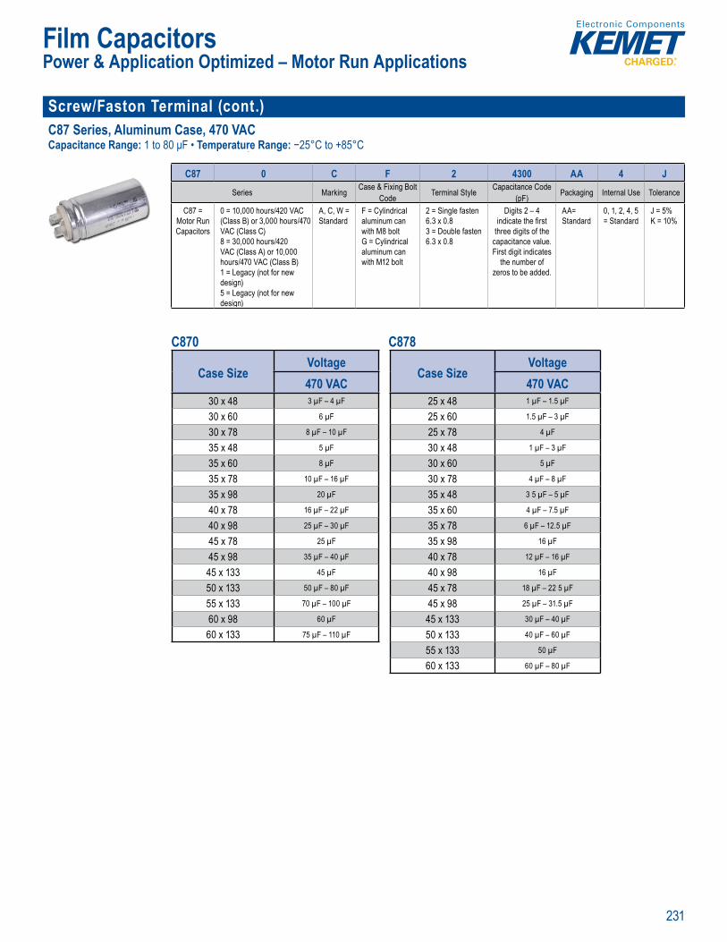
231
Film Capacitors
Screw/Faston Terminal (cont.)C87 Series, Aluminum Case, 470 VACCapacitance Range: 1 to 80 μF • Temperature Range: −25°C to +85°C
Part Number System
C87 0 C F 2 4300 AA 4 JSeries Marking Case & Fixing Bolt
Code Terminal Style Capacitance Code (pF) Packaging Internal Use Tolerance
C87 = Motor Run Capacitors
0 = 10,000 hours/420 VAC (Class B) or 3,000 hours/470 VAC (Class C)8 = 30,000 hours/420 VAC (Class A) or 10,000 hours/470 VAC (Class B)1 = Legacy (not for new design)5 = Legacy (not for new design)
A, C, W = Standard
F = Cylindrical aluminum can with M8 boltG = Cylindrical aluminum can with M12 bolt
2 = Single fasten 6.3 x 0.83 = Double fasten 6.3 x 0.8
Digits 2 – 4 indicate the fi rst
three digits of the capacitance value. First digit indicates
the number of zeros to be added.
AA= Standard
0, 1, 2, 4, 5 = Standard
J = 5%K = 10%
C870 C878
Case SizeVoltage470 VAC
30 x 48 3 µF – 4 µF
30 x 60 6 µF
30 x 78 8 µF – 10 µF
35 x 48 5 µF
35 x 60 8 µF
35 x 78 10 µF – 16 µF
35 x 98 20 µF
40 x 78 16 µF – 22 µF
40 x 98 25 µF – 30 µF
45 x 78 25 µF
45 x 98 35 µF – 40 µF
45 x 133 45 µF
50 x 133 50 µF – 80 µF
55 x 133 70 µF – 100 µF
60 x 98 60 µF
60 x 133 75 µF – 110 µF
Case SizeVoltage470 VAC
25 x 48 1 µF – 1.5 µF
25 x 60 1.5 µF – 3 µF
25 x 78 4 µF
30 x 48 1 µF – 3 µF
30 x 60 5 µF
30 x 78 4 µF – 8 µF
35 x 48 3 5 µF – 5 µF
35 x 60 4 µF – 7.5 µF
35 x 78 6 µF – 12.5 µF
35 x 98 16 µF
40 x 78 12 µF – 16 µF
40 x 98 16 µF
45 x 78 18 µF – 22 5 µF
45 x 98 25 µF – 31.5 µF
45 x 133 30 µF – 40 µF
50 x 133 40 µF – 60 µF
55 x 133 50 µF
60 x 133 60 µF – 80 µF
Power & Application Optimized – Motor Run Applications

232
Film Capacitors
Radial F43 Series, Integrated Resistor Metallized Polypropylene, 250 – 630 VDCCapacitance Range: 0.01 to 1.0 μF • Temperature Range: −55°C to +100°C
ar Number System
F 43 K N 3100 XX 01 M
Capacitor Class Series Rated Voltage (VAC)
Lead Spacing (mm)
Capacitance Code (pF) Packaging Internal Use Capacitance
ToleranceLegacy PN: F
New KEMET PN: Omit this character
RC Snubber, Metallized
Polypropylene
I = 160M = 200P = 220K = 275 (X2)
I = 15.0N = 22.5R = 27.5
The last three digits represent
signifi cant fi gures. The fi rst
digit specifi es number of zeros
to be added.
Contact KEMET for packaging
availability and details
00, 01, 04 (Standard)
K = ±10% M = ±20%
Case SizeVoltage
250/160 400/200 630/22015 – 18 x 14.5 x 8.5 250 nF
15 – 18 x 14.5 x 7.5 22 nF
22.5 – 26.5 x 15 x 6 330 nF
22.5 – 26.5 x 17 x 8.5 470 nF – 500 nF
22.5 – 26.5 x 18.5 x 10 1 µF 500 nF
22.5 – 26.5 x 16 x 7 250 nF 100 nF
22.5 – 26.5 x 20 x 11 250 nF
27.5 – 32 x 22 x 13 1 µF 500 nF
(X2)
Case SizeVoltage275 VAC
15 – 18 x 14.5 x 7.5 10 nF – 47 nF
15 – 18 x 16 x 10 68 nF
22.5 – 26.5 x 17 x 8.5 100 nF
22.5 – 26.5 x 20 x 10 150 nF
22.5 – 26.5 x 20 x 11 220 nF
27.5 – 32 x 20 x 11 250 nF – 330 nF
27.5 – 32 x 22 x 13 470 nF – 500 nF
27.5 – 32 x 33 x 18 680 nF – 1 µF
Power & Application Optimized – High Voltage Transient Suppression
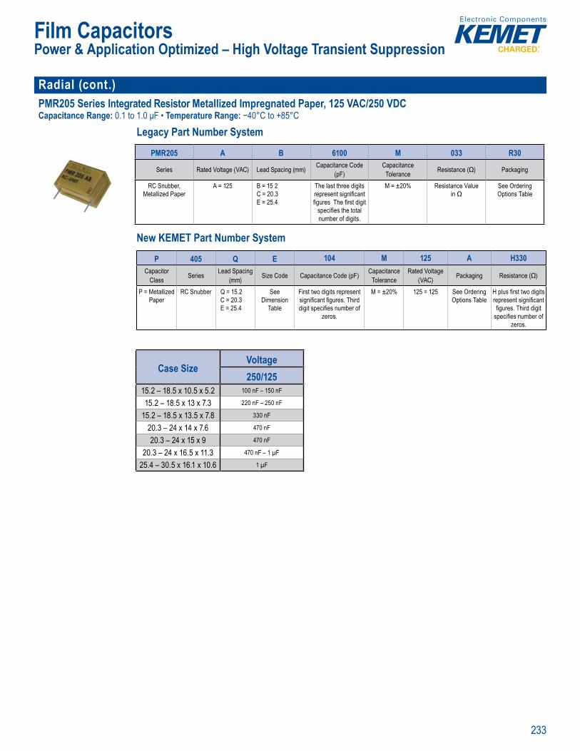
233
Film Capacitors
Radial (cont.)PMR205 Series Integrated Resistor Metallized Impregnated Paper, 125 VAC/250 VDCCapacitance Range: 0.1 to 1.0 μF • Temperature Range: −40°C to +85°C
Legacy Part Number System
• Lead spac
• Go d res stance to ionization due to impregnated p p r die ec ric
Legacy ar Number System
PMR205 A B 6100 M 033 R30
Series Rated Voltage (VAC) Lead Spacing (mm) Capacitance Code (pF)
CapacitanceTolerance Resistance (Ω) Packaging
RC Snubber, Metallized Paper
A = 125 B = 15 2C = 20.3E = 25.4
The last three digits represent signifi cant fi gures The fi rst digit
specifi es the total number of digits.
M = ±20% Resistance Value in Ω
See Ordering Options Table
New KEMET Part Number System
e spa Clima c c
ood i ta o o zat d e g te pap tr c
L a Nu y
(pF) T l ran e
Met llized Pap
C 2
25
rep esent signifi can fi gures T e fi rst dig
specifi es e t ta number of dig ts
in Ω
Opt ons Tabl
New KEMET Part Number System
P 405 Q E 104 M 125 A H330Capacitor
Class Series Lead Spacing(mm) Size Code Capacitance Code (pF) Capacitance
ToleranceRated Voltage
(VAC) Packaging Resistance (Ω)
P = Metallized Paper
RC Snubber Q = 15.2C = 20.3E = 25.4
See Dimension
Table
First two digits represent signifi cant fi gures. Third digit specifi es number of
zeros.
M = ±20% 125 = 125 See Ordering Options Table
H plus fi rst two digits represent signifi cant fi gures. Third digit
specifi es number of zeros.
Case SizeVoltage250/125
15.2 – 18.5 x 10.5 x 5.2 100 nF – 150 nF
15.2 – 18.5 x 13 x 7.3 220 nF – 250 nF
15.2 – 18.5 x 13.5 x 7.8 330 nF
20.3 – 24 x 14 x 7.6 470 nF
20.3 – 24 x 15 x 9 470 nF
20.3 – 24 x 16.5 x 11.3 470 nF – 1 µF
25.4 – 30.5 x 16.1 x 10.6 1 µF
Power & Application Optimized – High Voltage Transient Suppression
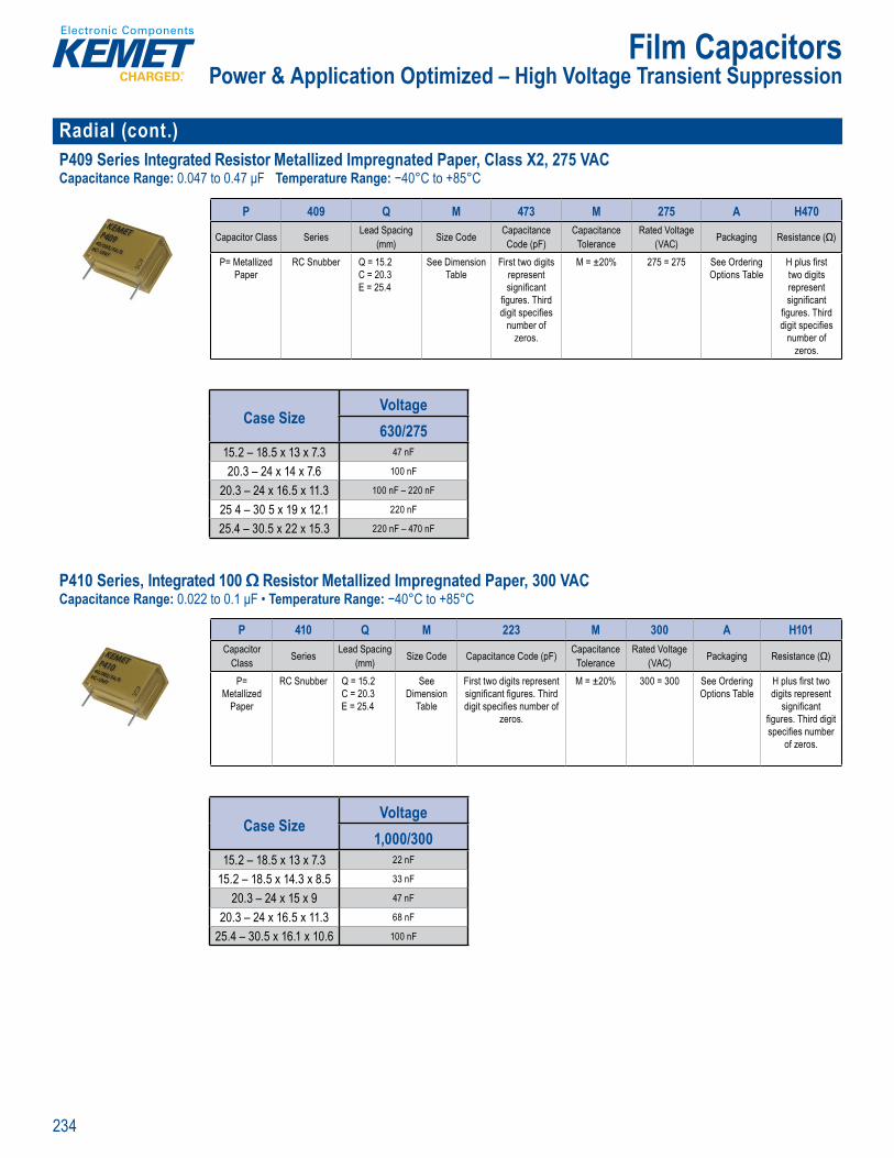
234
Film Capacitors
Radial (cont.)P409 Series Integrated Resistor Metallized Impregnated Paper, Class X2, 275 VACCapacitance Range: 0.047 to 0.47 μF Temperature Range: −40°C to +85°C
Part Num er System
P 409 Q M 473 M 275 A H470
Capacitor Class Series Lead Spacing(mm) Size Code Capacitance
Code (pF)Capacitance
ToleranceRated Voltage
(VAC) Packaging Resistance (Ω)
P= Metallized Paper
RC Snubber Q = 15.2C = 20.3E = 25.4
See Dimension Table
First two digits represent signifi cant
fi gures. Third digit specifi es
number of zeros.
M = ±20% 275 = 275 See Ordering Options Table
H plus fi rst two digits represent signifi cant
fi gures. Third digit specifi es
number of zeros.
Case SizeVoltage630/275
15.2 – 18.5 x 13 x 7.3 47 nF
20.3 – 24 x 14 x 7.6 100 nF
20.3 – 24 x 16.5 x 11.3 100 nF – 220 nF
25 4 – 30 5 x 19 x 12.1 220 nF
25.4 – 30.5 x 22 x 15.3 220 nF – 470 nF P410 Series, Integrated 100 Ω Resistor Metallized Impregnated Paper, 300 VACCapacitance Range: 0.022 to 0.1 μF • Temperature Range: −40°C to +85°C
Benefi s
pr al UL U 0 z ance with S Com liant a 0˚C to +85 x e n e he li g p h en
he jecte t f ag s il Im r n te a r e s t
pr pe tie arti u arl t o s ith con
ncapsulate and impr g ated in sel extingu s ing mate al
m e ng he q s L
co tac i terfe
Par u ber S stem
P 410 Q M 223 M 300 A H101Capacitor
Class Series Lead Spacing(mm) Size Code Capacitance Code (pF) Capacitance
ToleranceRated Voltage
(VAC) Packaging Resistance (Ω)
P= Metallized
Paper
RC Snubber Q = 15.2C = 20.3E = 25.4
See Dimension
Table
First two digits represent signifi cant fi gures. Third digit specifi es number of
zeros.
M = ±20% 300 = 300 See Ordering Options Table
H plus fi rst two digits represent
signifi cant fi gures. Third digit specifi es number
of zeros.
Case SizeVoltage
1,000/30015.2 – 18.5 x 13 x 7.3 22 nF
15.2 – 18.5 x 14.3 x 8.5 33 nF
20.3 – 24 x 15 x 9 47 nF
20.3 – 24 x 16.5 x 11.3 68 nF
25.4 – 30.5 x 16.1 x 10.6 100 nF
Power & Application Optimized – High Voltage Transient Suppression
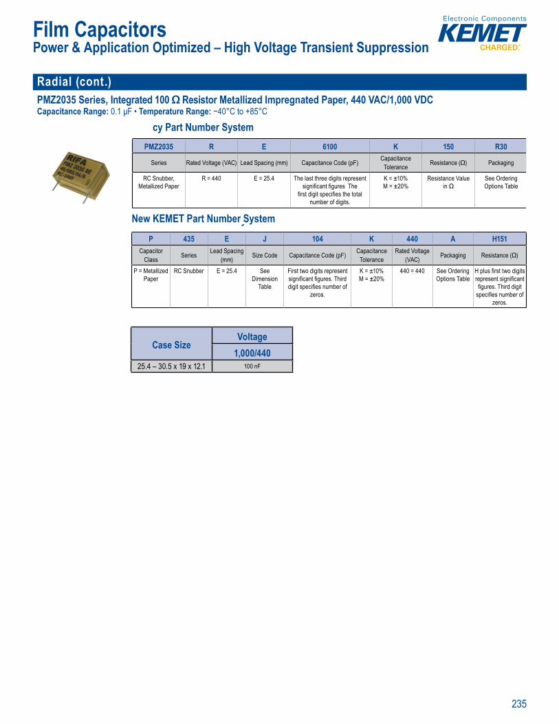
235
Film Capacitors
Radial (cont.) PMZ2035 Series, Integrated 100 Ω Resistor Metallized Impregnated Paper, 440 VAC/1,000 VDCCapacitance Range: 0.1 μF • Temperature Range: −40°C to +85°C
cy Part Number System
e st ead pa
G od resistance t o izati n e to imp e na e p pe
di
Legacy Part Number System
PMZ2035 R E 6100 K 150 R30
Series Rated Voltage (VAC) Lead Spacing (mm) Capacitance Code (pF) CapacitanceTolerance Resistance (Ω) Packaging
RC Snubber, Metallized Paper
R = 440 E = 25.4 The last three digits represent signifi cant fi gures The
fi rst digit specifi es the total number of digits.
K = ±10%M = ±20%
Resistance Value in Ω
See Ordering Options Table
New KEMET Part Number System
• Lead spa li
d ele tr c
L a Nu y
Tolerance
etal ized Pape
ignifi cant fi gures The
st di it specifi es th tot number of digits
M ± 0
in Ω
Options Table
New KEME Part Number SystemP 435 E J 104 K 440 A H151
Capacitor Class Series Lead Spacing
(mm) Size Code Capacitance Code (pF) CapacitanceTolerance
Rated Voltage (VAC) Packaging Resistance (Ω)
P = Metallized Paper
RC Snubber E = 25.4 See Dimension
Table
First two digits represent signifi cant fi gures. Third digit specifi es number of
zeros.
K = ±10%M = ±20%
440 = 440 See Ordering Options Table
H plus fi rst two digits represent signifi cant fi gures. Third digit
specifi es number of zeros.
Case SizeVoltage
1,000/44025.4 – 30.5 x 19 x 12.1 100 nF
Power & Application Optimized – High Voltage Transient Suppression
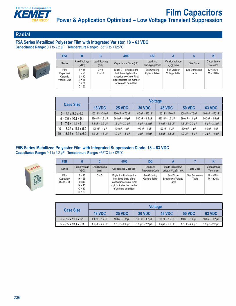
236
Film Capacitors
RadialF5A Series Metallized Polyester Film with Integrated Varistor, 18 – 63 VDCCapacitance Range: 0.1 to 2.2 μF Temperature Range: −55°C to +125°C
nce: ±10%, 0% 5 25 56 E 60068–1
Pa N mber System
F5A H C 4100 DQ A 6 K
Series Rated Voltage (VDC)
Lead Spacing (mm) Capacitance Code (pF) Lead and
Packaging CodeVaristor Voltage
Vv @ 1 mA Size Code CapacitanceTolerance
Film Capacitor/ Ceramic
Varistor Unit
B = 18H = 25J = 30N = 45C = 50D = 63
C = 5F = 10
Digits 2 – 4 indicate the fi rst three digits of the
capacitance value. First digit indicates the number
of zeros to be added.
See Ordering Options Table
See Varistor Voltage Table
See Dimension Table
K = ±10% M = ±20%
Case SizeVoltage
18 VDC 25 VDC 30 VDC 45 VDC 50 VDC 63 VDC5 – 7.4 x 9.6 x 4.6 100 nF – 470 nF 100 nF – 470 nF 100 nF – 470 nF 100 nF – 470 nF 100 nF – 470 nF 100 nF – 470 nF
5 – 7.5 x 10.1 x 5.1 560 nF – 1.5 µF 560 nF – 1.5 µF 560 nF – 1 5 µF 560 nF – 1.5 µF 560 nF – 1.5 µF 560 nF – 1.5 µF
5 – 7.5 x 11.1 x 6.1 1.8 µF – 2.2 µF 1.8 µF – 2.2 µF 1.8 µF – 2.2 µF 1.8 µF – 2.2 µF 1.8 µF – 2.2 µF 1.8 µF – 2.2 µF
10 – 13.35 x 11.1 x 5.2 100 nF – 1 µF 100 nF – 1 µF 100 nF – 1 µF 100 nF – 1 µF 100 nF – 1 µF 100 nF – 1 µF
10 – 13.35 x 12.1 x 6.2 1.2 µF – 1 5 µF 1.2 µF – 1.5 µF 1.2 µF – 1.5 µF 1.2 µF – 1.5 µF 1.2 µF – 1 5 µF 1.2 µF – 1.5 µF
F5B Series Metallized Polyester Film with Integrated Suppression Diode, 18 – 63 VDCCapacitance Range: 0.1 to 2.2 μF Temperature Range: −55°C to +125°C
o nductive MKT ors in p le st uctio with g ower b d ec o ns en vo tag sso diode gl se p ovi e s o up res ul s
s 2 ),
• Lead sp g 5 mm• a acit to e nce ±1 ±2 % m ti o : 125 C 8 p g
y an nt pr s e ted in a
terial is s re st a r meeting t e ui emen L 9 V
d e tr lt e p rs for au e t
p ns, cen al lo systems, h -con b o ers,
Pa N mber System
F5B H C 4100 DQ A 7 K
Series Rated Voltage (VDC)
Lead Spacing (mm) Capacitance Code (pF) Lead and
Packaging CodeDiode Breakdown
Voltage VBR @ 1 mA Size Code CapacitanceTolerance
Film Capacitor/Diode Unit
B = 18H = 25J = 30N = 45C = 50D = 63
C = 5 Digits 2 – 4 indicate the fi rst three digits of the
capacitance value. First digit indicates the number
of zeros to be added.
See Ordering Options Table
See Diode Breakdown Voltage
Table
See Dimension Table
K = ±10% M = ±20%
Case SizeVoltage
18 VDC 25 VDC 30 VDC 45 VDC 50 VDC 63 VDC5 – 7.5 x 11.1 x 6.1 100 nF – 1.2 µF 100 nF – 1.2 µF 100 nF – 1 2 µF 100 nF – 1.2 µF 100 nF – 1.2 µF 100 nF – 1.2 µF
5 – 7.5 x 13.1 x 7.3 1.5 µF – 2.2 µF 1 5 µF – 2.2 µF 1.5 µF – 2.2 µF 1.5 µF – 2.2 µF 1.5 µF – 2.2 µF 1 5 µF – 2.2 µF
Power & Application Optimized – Low Voltage Transient Suppression

237
Film Capacitors
Radial (cont.)F5D Series Metallized Polyester Film with Integrated Ceramic Capacitor, 63 – 100 VDCCapacitance Range: 0.1 to 2.2 μF Temperature Range: −55°C to +125°C
a cer mic
Pa t N mber System
F5D D C 3100 DQ W 5 M
Series Rated Voltage (VDC)
Lead Spacing (mm) Capacitance Code (pF) Lead and
Packaging CodeCeramic Capacitor
Value Size Code CapacitanceTolerance
Film Capacitor/ Ceramic
Capacitor Unit
D = 63E = 100
C = 5 mmF= 10 mm
Digits 2 – 4 indicate the fi rst three digits of the
capacitance value. First digit indicates the number
of zeros to be added.
See Ordering Options Table
See Ceramic Capacitor Table
See Dimension Table
K = ±10% M = ±20%
Case SizeVoltage
63 VDC 100 VDC5 – 7.4 x 9.6 x 4.6 100 nF – 470 nF 100 nF – 470 nF
5 – 7.5 x 10.1 x 5.1 560 nF – 1.5 µF 560 nF – 1.5 µF
5 – 7.5 x 11.1 x 6.1 1.8 µF – 2.2 µF 1.8 µF – 2.2 µF
10 – 13.35 x 11.1 x 5.2 100 nF – 1 µF 100 nF – 1 µF
10 – 13.35 x 12.1 x 6.2 1 2 µF – 1.5 µF 1 2 µF – 1.5 µF
Power & Application Optimized – Low Voltage Transient Suppression

238
Film Capacitors
Radial F862 Series, Metallized Polypropylene, 310 VAC (Automotive Grade)Capacitance Range: 0.1 to 4.7 μF • Temperature Range: −40°C to +110°C
Pa t N mber System
F 862 B C 104 M 310 C
Capacitor Class Series Lead Spacing (mm) Size Code Capacitance Code (pF)
CapacitanceTolerance Voltage (VAC) Packaging
F = Film X2, Metallized Polypropylene
B = 15D = 22.5F = 27 5
See Dimension Table
First two digits represent signifi cant
fi gures. Third digit specifi es
number of zeros.
K = ±10% M = ±20%
310 See Ordering Options Table
Case SizeVoltage310 VAC
15 – 18 x 13.5 x 7.5 100 nF – 150 nF
15 – 18 x 14.5 x 8.5 180 nF – 220 nF
15 – 18 x 16 x 10 330 nF – 390 nF
15 – 18 x 19 x 11 470 nF
15 – 18 x 20 x 12 560 nF
22.5 – 26 x 18.5 x 10 470 nF – 560 nF
22.5 – 26 x 20 x 11 680 nF – 820 nF
22.5 – 26 x 22 x 13 1 µF – 1.2 µF
27.5 – 31.5 x 20 x 11 1 µF
27.5 – 31.5 x 25 x 13 1.5 µF
27.5 – 31.5 x 28 x 14 2.2 µF
27.5 – 31.5 x 29 x 19 3.3 µF
27.5 – 31.5 x 37 x 22 4.7 µF
Power & Application Optimized – Capacitive AC Power Supply
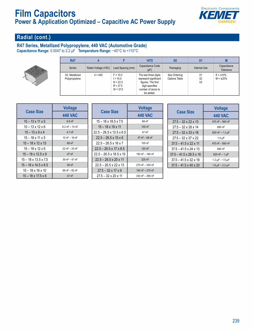
239
Film Capacitors
Radial (cont.)R47 Series, Metallized Polypropylene, 440 VAC (Automotive Grade)Capacitance Range: 0.0047 to 2.2 μF Temperature Range: −40°C to +110°C
• RoHS Co p r in
Pa t Num er System
R47 4 F 1470 00 01 M
Series Rated Voltage (VAC) Lead Spacing (mm) Capacitance Code (pF) Packaging Internal Use Capacitance
ToleranceX2, Metallized Polypropylene
4 = 440 F = 10.0I = 15.0N = 22.5R = 27 5W = 37.5
The last three digits represent signifi cant
fi gures. The fi rst digit specifi es
number of zeros to be added.
See Ordering Options Table
010203
K = ±10% M = ±20%
Case SizeVoltage440 VAC
10 – 13 x 11 x 5 6.8 nF
10 – 13 x 12 x 6 8.2 nF – 10 nF
10 – 13 x 9 x 4 4.7 nF
15 – 18 x 11 x 5 10 nF – 18 nF
15 – 18 x 12 x 13 68 nF
15 – 18 x 12 x 6 22 nF – 33 nF
15 – 18 x 12.5 x 9 47 nF
15 – 18 x 13.5 x 7.5 39 nF – 47 nF
15 – 18 x 14.5 x 8.5 56 nF
15 – 18 x 16 x 10 68 nF – 82 nF
15 – 18 x 17.5 x 6 47 nF
Case SizeVoltage440 VAC
15 – 18 x 18.5 x 7.5 68 nF
15 – 18 x 19 x 11 100 nF
22.5 – 26.5 x 13.5 x 6.5 47 nF
22.5 – 26.5 x 15 x 6 47 nF – 68 nF
22.5 – 26.5 x 16 x 7 100 nF
22.5 – 26.5 x 17 x 8.5 120 nF
22.5 – 26.5 x 18.5 x 10 150 nF – 180 nF
22.5 – 26.5 x 20 x 11 220 nF
22.5 – 26.5 x 22 x 13 270 nF – 330 nF
27.5 – 32 x 17 x 9 150 nF – 270 nF
27.5 – 32 x 20 x 11 330 nF – 390 nF
Case SizeVoltage440 VAC
27.5 – 32 x 22 x 13 470 nF – 560 nF
27.5 – 32 x 28 x 14 680 nF
27.5 – 32 x 33 x 18 820 nF – 1 2 µF
27.5 – 32 x 37 x 22 1.5 µF
37.5 – 41.5 x 22 x 11 470 nF – 560 nF
37.5 – 41.5 x 24 x 13 680 nF
37.5 – 41.5 x 28.5 x 16 820 nF – 1 µF
37.5 – 41.5 x 32 x 19 1.2 µF – 1.5 µF
37.5 – 41.5 x 40 x 20 1.8 µF – 2.2 µF
Power & Application Optimized – Capacitive AC Power Supply
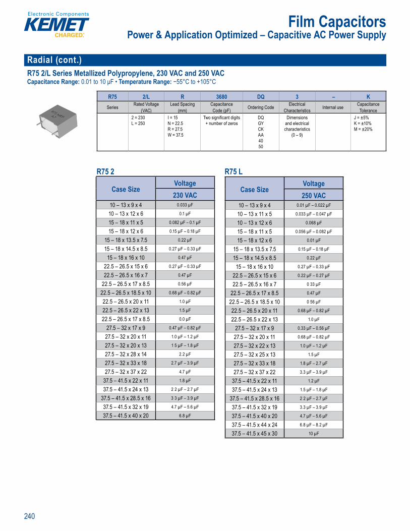
240
Film Capacitors
Radial (cont.)R75 2/L Series Metallized Polypropylene, 230 VAC and 250 VACCapacitance Range: 0.01 to 10 μF • Temperature Range: −55°C to +105°C
Part Number Sy tem
R75 2/L R 3680 DQ 3 – KSeries Rated Voltage
(VAC)Lead Spacing
(mm)Capacitance Code (pF) Ordering Code Electrical
Characteristics Internal use CapacitanceTolerance
2 = 230 L = 250
I = 15N = 22.5R = 27.5W = 37.5
Two signifi cant digits + number of zeros
DQGY CK AA4050
Dimensions and electrical characteristics
(0 – 9)
J = ±5%K = ±10%M = ±20%
R75 2 R75 L
Case SizeVoltage230 VAC
10 – 13 x 9 x 4 0.033 µF
10 – 13 x 12 x 6 0.1 µF
15 – 18 x 11 x 5 0.082 µF – 0.1 µF
15 – 18 x 12 x 6 0.15 µF – 0.18 µF
15 – 18 x 13.5 x 7.5 0.22 µF
15 – 18 x 14.5 x 8.5 0.27 µF – 0.33 µF
15 – 18 x 16 x 10 0.47 µF
22.5 – 26.5 x 15 x 6 0.27 µF – 0.33 µF
22.5 – 26.5 x 16 x 7 0.47 µF
22.5 – 26.5 x 17 x 8.5 0.56 µF
22.5 – 26.5 x 18.5 x 10 0.68 µF – 0.82 µF
22.5 – 26.5 x 20 x 11 1.0 µF
22.5 – 26.5 x 22 x 13 1.5 µF
22.5 – 26.5 x 17 x 8.5 0.0 µF
27.5 – 32 x 17 x 9 0.47 µF – 0.82 µF
27.5 – 32 x 20 x 11 1.0 µF – 1.2 µF
27.5 – 32 x 20 x 13 1 5 µF – 1.8 µF
27.5 – 32 x 28 x 14 2.2 µF
27.5 – 32 x 33 x 18 2.7 µF – 3.9 µF
27.5 – 32 x 37 x 22 4.7 µF
37.5 – 41.5 x 22 x 11 1.8 µF
37.5 – 41.5 x 24 x 13 2 2 µF – 2.7 µF
37.5 – 41.5 x 28.5 x 16 3 3 µF – 3.9 µF
37.5 – 41.5 x 32 x 19 4.7 µF – 5.6 µF
37.5 – 41.5 x 40 x 20 6.8 µF
Case SizeVoltage250 VAC
10 – 13 x 9 x 4 0.01 µF – 0.022 µF
10 – 13 x 11 x 5 0.033 µF – 0.047 µF
10 – 13 x 12 x 6 0.068 µF
15 – 18 x 11 x 5 0.056 µF – 0.082 µF
15 – 18 x 12 x 6 0.01 µF
15 – 18 x 13.5 x 7.5 0.15 µF – 0.18 µF
15 – 18 x 14.5 x 8.5 0.22 µF
15 – 18 x 16 x 10 0.27 µF – 0.33 µF
22.5 – 26.5 x 15 x 6 0.22 µF – 0.27 µF
22.5 – 26.5 x 16 x 7 0 33 µF
22.5 – 26.5 x 17 x 8.5 0.47 µF
22.5 – 26.5 x 18.5 x 10 0 56 µF
22.5 – 26.5 x 20 x 11 0.68 µF – 0.82 µF
22.5 – 26.5 x 22 x 13 1.0 µF
27.5 – 32 x 17 x 9 0.33 µF – 0.56 µF
27.5 – 32 x 20 x 11 0.68 µF – 0.82 µF
27.5 – 32 x 22 x 13 1.0 µF – 1.2 µF
27.5 – 32 x 25 x 13 1.5 µF
27.5 – 32 x 33 x 18 1.8 µF – 2.7 µF
27.5 – 32 x 37 x 22 3.3 µF – 3.9 µF
37.5 – 41.5 x 22 x 11 1.2 µF
37.5 – 41.5 x 24 x 13 1.5 µF – 1.8 µF
37.5 – 41.5 x 28.5 x 16 2 2 µF – 2.7 µF
37.5 – 41.5 x 32 x 19 3.3 µF – 3.9 µF
37.5 – 41.5 x 40 x 20 4.7 µF – 5.6 µF
37.5 – 41.5 x 44 x 24 6.8 µF – 8.2 µF
37.5 – 41.5 x 45 x 30 10 µF
Power & Application Optimized – Capacitive AC Power Supply
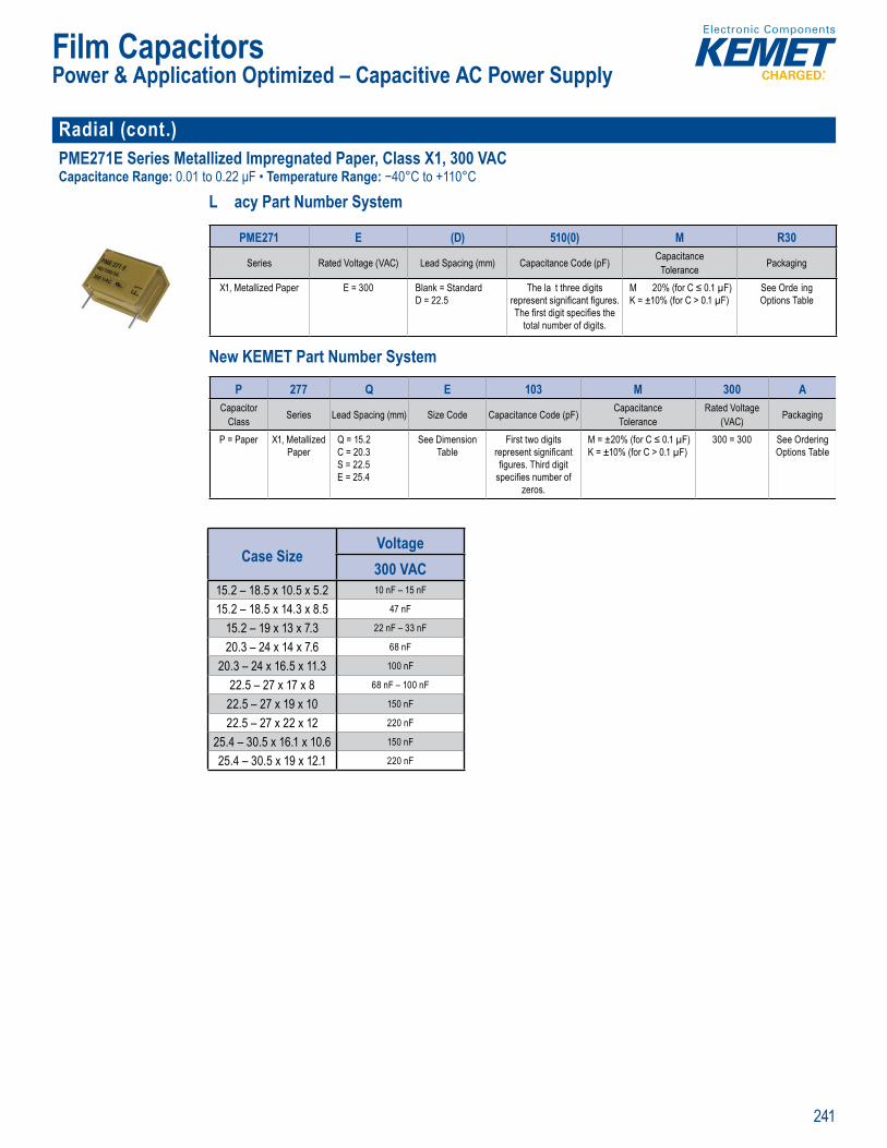
241
Film Capacitors
Radial (cont.)PME271E Series Metallized Impregnated Paper, Class X1, 300 VACCapacitance Range: 0.01 to 0.22 μF • Temperature Range: −40°C to +110°C
L acy Part Number System
Capa itan g
fl ammabi ity
Legacy Part Number System
PME271 E (D) 510(0) M R30
Series Rated Voltage (VAC) Lead Spacing (mm) Capacitance Code (pF) CapacitanceTolerance Packaging
X1, Metallized Paper E = 300 Blank = StandardD = 22.5
The la t three digits represent signifi cant fi gures. The fi rst digit specifi es the
total number of digits.
M 20% (for C ≤ 0.1 µF)K = ±10% (for C > 0.1 µF)
See Orde ing Options Table
New KEMET Part Number System
Clima ic c
y
c tTo erance
D = 2
esent signifi cant fi gu
The fi rst digit speci es the tota number of digits.
% f r C K = ±10 (for µF)
Options Tab e
New KEME Part Number System
P 277 Q E 103 M 300 ACapacitor
Class Series Lead Spacing (mm) Size Code Capacitance Code (pF) CapacitanceTolerance
Rated Voltage (VAC) Packaging
P = Paper X1, Metallized Paper
Q = 15.2C = 20.3S = 22.5E = 25.4
See Dimension Table
First two digits represent signifi cant fi gures. Third digit
specifi es number of zeros.
M = ±20% (for C ≤ 0.1 µF)K = ±10% (for C > 0.1 µF)
300 = 300 See Ordering Options Table
Case SizeVoltage300 VAC
15.2 – 18.5 x 10.5 x 5.2 10 nF – 15 nF
15.2 – 18.5 x 14.3 x 8.5 47 nF
15.2 – 19 x 13 x 7.3 22 nF – 33 nF
20.3 – 24 x 14 x 7.6 68 nF
20.3 – 24 x 16.5 x 11.3 100 nF
22.5 – 27 x 17 x 8 68 nF – 100 nF
22.5 – 27 x 19 x 10 150 nF
22.5 – 27 x 22 x 12 220 nF
25.4 – 30.5 x 16.1 x 10.6 150 nF
25.4 – 30.5 x 19 x 12.1 220 nF
Power & Application Optimized – Capacitive AC Power Supply
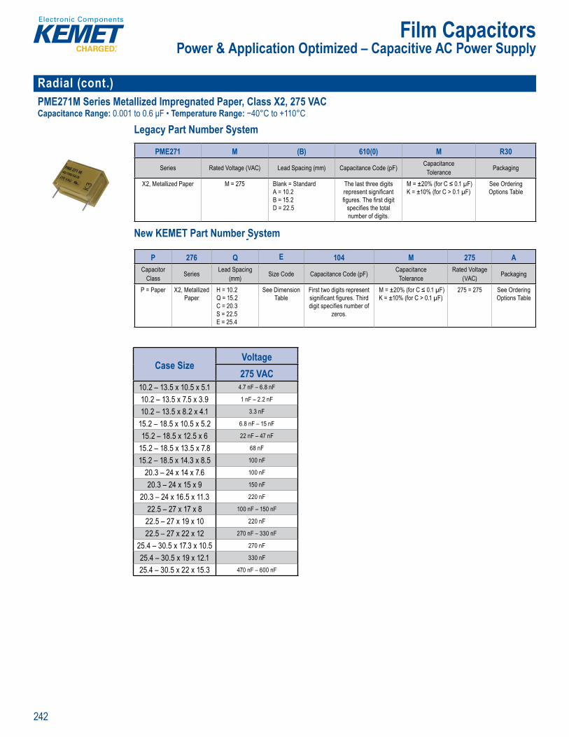
242
Film Capacitors
Radial (cont.)PME271M Series Metallized Impregnated Paper, Class X2, 275 VACCapacitance Range: 0.001 to 0.6 μF • Temperature Range: −40°C to +110°C
Legacy Part Number System
• 1 0% screeni g fac ory test at 2, 0 V C
Legacy Part Number System
PME271 M (B) 610(0) M R30
Series Rated Voltage (VAC) Lead Spacing (mm) Capacitance Code (pF) CapacitanceTolerance Packaging
X2, Metallized Paper M = 275 Blank = StandardA = 10.2B = 15.2D = 22.5
The last three digits represent signifi cant fi gures. The fi rst digit
specifi es the total number of digits.
M = ±20% (for C ≤ 0.1 µF)K = ±10% (for C > 0.1 µF)
See Ordering Options Table
New KEMET Part Number System
L c t N S t
i citTo eranc
A 1B 15 2D = 5
epresent sign fi cant gures. The rst digit spec fi es the total numbe of d g ts.
% (for C K ±1 % ( o C F)
Opt ns ab e
New KEME Part Number System
P 276 Q E 104 M 275 ACapacitor
Class Series Lead Spacing (mm) Size Code Capacitance Code (pF) Capacitance
ToleranceRated Voltage
(VAC) Packaging
P = Paper X2, Metallized Paper
H = 10.2Q = 15.2C = 20.3S = 22.5E = 25.4
See Dimension Table
First two digits represent signifi cant fi gures. Third digit specifi es number of
zeros.
M = ±20% (for C ≤ 0.1 µF)K = ±10% (for C > 0.1 µF)
275 = 275 See Ordering Options Table
Case SizeVoltage275 VAC
10.2 – 13.5 x 10.5 x 5.1 4.7 nF – 6.8 nF
10.2 – 13.5 x 7.5 x 3.9 1 nF – 2.2 nF
10.2 – 13.5 x 8.2 x 4.1 3.3 nF
15.2 – 18.5 x 10.5 x 5.2 6.8 nF – 15 nF
15.2 – 18.5 x 12.5 x 6 22 nF – 47 nF
15.2 – 18.5 x 13.5 x 7.8 68 nF
15.2 – 18.5 x 14.3 x 8.5 100 nF
20.3 – 24 x 14 x 7.6 100 nF
20.3 – 24 x 15 x 9 150 nF
20.3 – 24 x 16.5 x 11.3 220 nF
22.5 – 27 x 17 x 8 100 nF – 150 nF
22.5 – 27 x 19 x 10 220 nF
22.5 – 27 x 22 x 12 270 nF – 330 nF
25.4 – 30.5 x 17.3 x 10.5 270 nF
25.4 – 30.5 x 19 x 12.1 330 nF
25.4 – 30.5 x 22 x 15.3 470 nF – 600 nF
Power & Application Optimized – Capacitive AC Power Supply

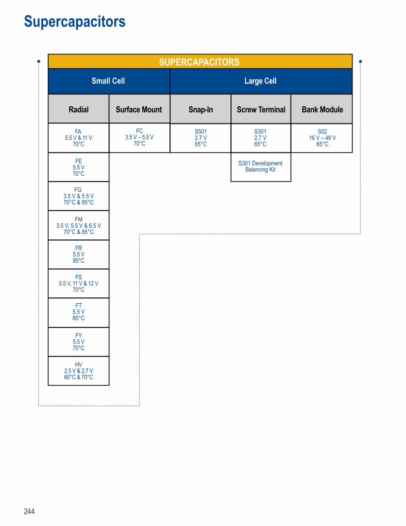
244
Supercapacitors
SUPERCAPACITORS
Small Cell Large Cell
FA 5.5 V & 11 V
70°C
S3012.7 V65°C
S5012.7 V65°C
S0216 V – 48 V
65°C
FC3.5 V – 5.5 V
70°C
S301 DevelopmentBalancing Kit
FE5.5 V70°C
Radial Screw TerminalSnap-InSurface Mount Bank Module
FG 3.5 V & 5.5 V70°C & 85°C
FM3.5 V, 5.5 V & 6.5 V
70°C & 85°C
FT5.5 V85°C
FY5.5 V70°C
HV2.5 V & 2.7 V60°C & 70°C
FR5.5 V85°C
FS5.5 V, 11 V & 12 V
70°C
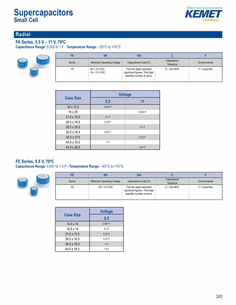
245
Supercapacitors
Radial FA Series, 5.5 V – 11 V, 70ºC Capacitance Range: 0.022 to 1 F Temperature Range: −25°C to +70°C
P r Number System
FA 0H 104 Z F
Series Maximum Operating Voltage Capacitance Code (F) CapacitanceTolerance Environmental
FA 0H = 5.5 VDC1A = 11.0 VDC
First two digits represent signifi cant fi gures. Third digit specifi es number of zeros.
Z = -20/+80% F = Lead-free
Case SizeVoltage
5.5 1116 x 15.5 0.047 F
16 x 25 0.022 F
21.5 x 15.5 0.1 F
28 5 x 16.5 0.22 F
28.5 x 25.5 0.1 F
36.5 x 16.5 0.47 F
36.5 x 27.5 0.22 F
44.5 x 18.5 1 F
44.5 x 28.5 0.47 F
FE Series, 5.5 V, 70ºC Capacitance Range: 0.047 to 1.5 F • Temperature Range: −40°C to +70°C
f fr um pe a i rel able ag ree n Ro
verv
FE e er c t so w El t i D
tt hese est suited o tage DC ho
mbe fl ash me
Par Nu ber System
FE 0H 104 Z F
Series Maximum Operating Voltage Capacitance Code (F) CapacitanceTolerance Environmental
FE 0H = 5.5 VDC First two digits represent signifi cant fi gures. Third digit specifi es number of zeros.
Z = -20/+80% F = Lead-free
Case SizeVoltage
5.514.5 x 14 0.047 F
16.5 x 14 0.1 F
21.5 x 15.5 0.22 F
28.5 x 16.5 0.47 F
36.5 x 18.5 1 F
44.5 x 18.5 1.5 F
Small Cell
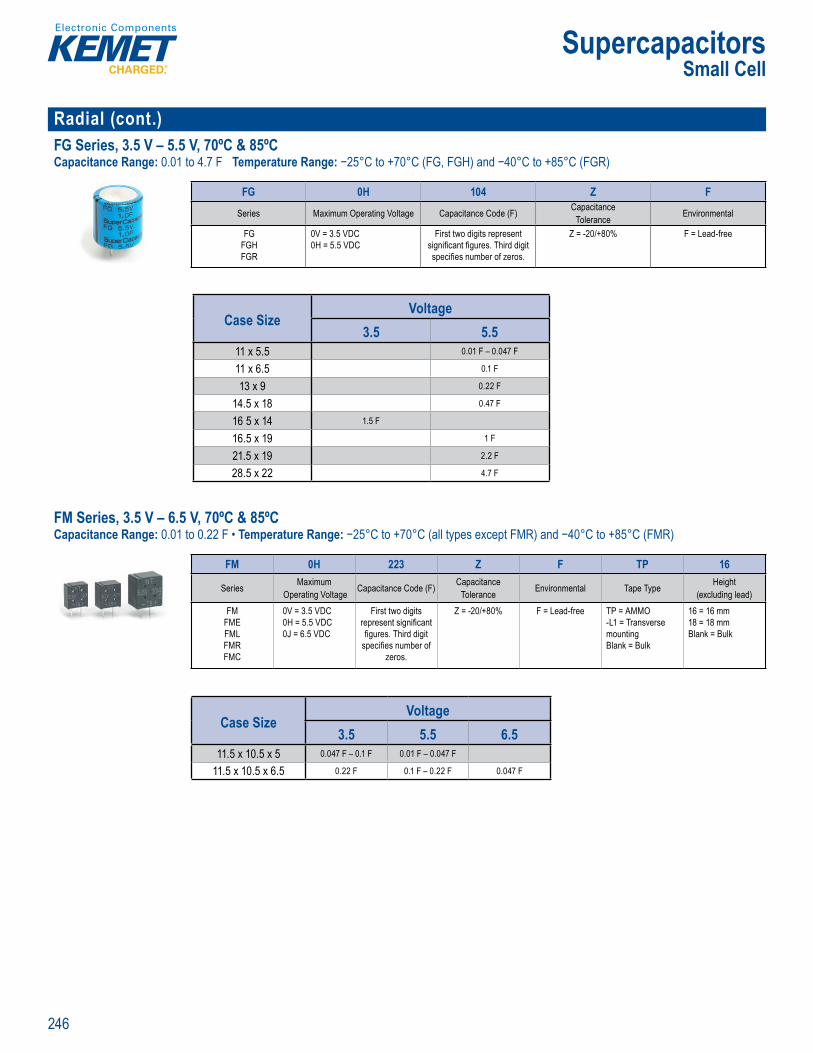
246
Supercapacitors
Radial (cont.)FG Series, 3.5 V – 5.5 V, 70ºC & 85ºCCapacitance Range: 0.01 to 4.7 F Temperature Range: −25°C to +70°C (FG, FGH) and −40°C to +85°C (FGR)
Par Number System
FG 0H 104 Z F
Series Maximum Operating Voltage Capacitance Code (F) CapacitanceTolerance Environmental
FGFGHFGR
0V = 3.5 VDC0H = 5.5 VDC
First two digits represent signifi cant fi gures. Third digit specifi es number of zeros.
Z = -20/+80% F = Lead-free
Case SizeVoltage
3.5 5.511 x 5.5 0.01 F – 0.047 F
11 x 6.5 0.1 F
13 x 9 0.22 F
14.5 x 18 0.47 F
16 5 x 14 1.5 F
16.5 x 19 1 F
21.5 x 19 2.2 F
28.5 x 22 4.7 F
FM Series, 3.5 V – 6.5 V, 70ºC & 85ºCCapacitance Range: 0.01 to 0.22 F • Temperature Range: −25°C to +70°C (all types except FMR) and −40°C to +85°C (FMR)
g f e
MR) an ce r an be ra
L er Cap ci ors (E a plica s
us d like s condar bat ery
e te
Part Nu ber System
FM 0H 223 Z F TP 16
Series Maximum Operating Voltage Capacitance Code (F) Capacitance
Tolerance Environmental Tape Type Height (excluding lead)
FMFMEFMLFMRFMC
0V = 3.5 VDC0H = 5.5 VDC0J = 6.5 VDC
First two digits represent signifi cant fi gures. Third digit
specifi es number of zeros.
Z = -20/+80% F = Lead-free TP = AMMO-L1 = Transverse mountingBlank = Bulk
16 = 16 mm18 = 18 mmBlank = Bulk
Case SizeVoltage
3.5 5.5 6.511.5 x 10.5 x 5 0.047 F – 0.1 F 0.01 F – 0.047 F
11.5 x 10.5 x 6.5 0.22 F 0.1 F – 0.22 F 0.047 F
Small Cell
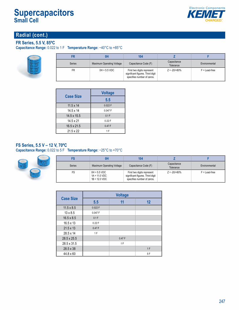
247
Supercapacitors
Radial (cont.)FR Series, 5.5 V, 85ºC Capacitance Range: 0.022 to 1 F Temperature Range: −40°C to +85°C
Part Number System
FR 0H 104 Z F
Series Maximum Operating Voltage Capacitance Code (F) CapacitanceTolerance Environmental
FR 0H = 5.5 VDC First two digits represent signifi cant fi gures. Third digit specifi es number of zeros.
Z = -20/+80% F = Lead-free
Case SizeVoltage
5.511.5 x 14 0.022 F
14.5 x 14 0.047 F
14.5 x 15.5 0.1 F
14.5 x 21 0.22 F
16.5 x 21.5 0.47 F
21.5 x 22 1 F
FS Series, 5.5 V – 12 V, 70ºCCapacitance Range: 0.022 to 5 F Temperature Range: −25°C to +70°C
5 C to +7 tenanc f ee e a le a ee a R
S
Part Number System
FS 0H 104 Z F
Series Maximum Operating Voltage Capacitance Code (F) CapacitanceTolerance Environmental
FS 0H = 5.5 VDC1A = 11.0 VDC1B = 12.0 VDC
First two digits represent signifi cant fi gures. Third digit specifi es number of zeros.
Z = -20/+80% F = Lead-free
Case SizeVoltage
5.5 11 1211.5 x 8.5 0.022 F
13 x 8.5 0.047 F
16.5 x 8.5 0.1 F
16.5 x 13 0.22 F
21.5 x 13 0.47 F
28.5 x 14 1 F
28.5 x 25.5 0.47 F
28.5 x 31.5 1 F
28.5 x 38 1 F
44.8 x 60 5 F
Small Cell

248
Supercapacitors
Radial (cont.)FT Series, 5.5 V, 85ºCCapacitance Range: 0.1 to 5.6 F • Temperature Range: −40°C to +85°C
Pa t umbe System
FT 0H 104 Z F
Series Maximum Operating Voltage Capacitance Code (F) CapacitanceTolerance Environmental
FTFTW
0H = 5.5 VDC First two digits represent signifi cant fi gures. Third digit specifi es number of zeros.
Z = -20/+80% F = Lead-free
Case SizeVoltage
5.511.5 x 8.5 0.1 F
14.5 x 12 0.22 F
16.5 x 13 0.47 F
21.5 x 13 1 F
28.5 x 14 2.2 F
36.5 x 15 3 3 F
44.5 x 17 5.6 F FY Series, 5.5 V, 70ºCCapacitance Range: 0.01 to 2.2 F • Temperature Range: −25°C to +70°C
range of tem um pe a e a a
art N mber System
FY 0H 104 Z F
Series Maximum Operating Voltage Capacitance Code (F) CapacitanceTolerance Environmental
FYDFYHFYL
0H = 5.5 VDC First two digits represent signifi cant fi gures. Third digit specifi es number of zeros.
Z = -20/+80% F = Lead-free
FYD FYH FYL
Case SizeVoltage
5.511.5 x 8.5 0.022 F – 0.047 F
13 x 8.5 0.1 F
14.5 x 15 0 22 F
16.5 x 15 0.47 F
21.5 x 16 1 F
21.5 x 19 1.4 F
28.5 x 22 2.2 F
Case SizeVoltage
5.511.5 x 7 0.022 F
13 x 7 0.047 F
16.5 x 7.5 0.1 F
16.5 x 9.5 0.22 F
21.5 x 10 0.47 F
28.5 x 11 1 F
Case SizeVoltage
5.511 x 5 0.01 F – 0.022 F
12 x 5 0.047 F
Small Cell
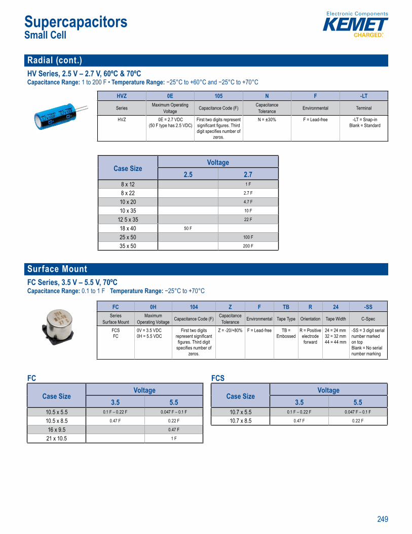
249
Supercapacitors
Radial (cont.)HV Series, 2.5 V – 2.7 V, 60ºC & 70ºCCapacitance Range: 1 to 200 F • Temperature Range: −25°C to +60°C and −25°C to +70°C
Le d ree a
Part Number Sy tem
HVZ 0E 105 N F -LT
Series Maximum Operating Voltage Capacitance Code (F) Capacitance
Tolerance Environmental Terminal
HVZ 0E = 2.7 VDC(50 F type has 2.5 VDC)
First two digits represent signifi cant fi gures. Third digit specifi es number of
zeros.
N = ±30% F = Lead-free -LT = Snap-inBlank = Standard
Case SizeVoltage
2.5 2.78 x 12 1 F
8 x 22 2.7 F
10 x 20 4.7 F
10 x 35 10 F
12 5 x 35 22 F
18 x 40 50 F
25 x 50 100 F
35 x 50 200 F
Surface Mount FC Series, 3.5 V – 5.5 V, 70ºC Capacitance Range: 0.1 to 1 F Temperature Range: −25°C to +70°C
m nt f Volt eli b e ag e and R
O erview
FC rcap t rs al o no s ect ic Doub p
f i spec efl w s l e i g g them to be (P
e
se d vic s uited for use e DC ho
i
Pa t Number Sy tem
FC 0H 104 Z F TB R 24 -SSSeries
Surface MountMaximum
Operating Voltage Capacitance Code (F) CapacitanceTolerance Environmental Tape Type Orientation Tape Width C-Spec
FCSFC
0V = 3.5 VDC0H = 5.5 VDC
First two digits represent signifi cant fi gures. Third digit
specifi es number of zeros.
Z = -20/+80% F = Lead-free TB = Embossed
R = Positive electrode forward
24 = 24 mm32 = 32 mm44 = 44 mm
-SS = 3 digit serial number marked on topBlank = No serial number marking
FC
Case SizeVoltage
3.5 5.510.5 x 5.5 0.1 F – 0.22 F 0.047 F – 0.1 F
10.5 x 8.5 0.47 F 0.22 F
16 x 9.5 0.47 F
21 x 10.5 1 F
FCS
Case SizeVoltage
3.5 5.510.7 x 5.5 0.1 F – 0.22 F 0.047 F – 0.1 F
10.7 x 8.5 0.47 F 0.22 F
Small Cell

250
Supercapacitors
Snap-In S501 Series, 2.7 V, 65ºC Capacitance Range: 100 to 350 F Temperature Range: −40°C to +65°C
ar N mber System
S501 DC 107 V 2R7 A
Series Size Code (D x L) Capacitance Code (µF) CapacitanceTolerance
Rated Voltage (VDC) Termination Code
Supercapacitor, Snap-In
Termination
DC = 22 x 45LF = 35 x 60LI = 35 x 69LR = 35 x 89
First two digits represent signifi cant fi gures. Third digit specifi es number of zeros.
V = -5/+10% W = -0/+20%
2R7 = 2.7 A = 2 pin, 10 mm lead spacing, 5.9 mm terminal lengthU = 4 pin standard snap-in style
Case SizeVoltage
2.722 x 45 100 F
35 x 60 350 F
35 x 62 350 F
Screw Terminal S301 Series, 2.7 V, 65ºC Capacitance Range: 1,200 to 3,000 F • Temperature Range: −40°C to +65°C
nefi ts
r cl g life c e l fe > om l a n USA
P N e
S301 RV 308 T 2R7 W
Series Size Code (D x L) Capacitance Code (µF) CapacitanceTolerance
Rated Voltage (VDC) Termination Code
Supercapacitor, Screw Termination
RP = 60.5 x 80.5RS = 60.5 x 108.5 RV = 60.5 x 144
First two digits represent signifi cant fi gures. Third digit specifi es number of zeros.
R = -0% 2R7 = 2.7 2 threaded inserts per end, 20 mm lead spacing, M6
Case SizeVoltage
2.760.7 x 80 1200 F
60.7 x 108.5 2000 F
60.7 x 144 3000 F S301 Development Balancing KitCapacitance Range: 1,200 to 3,000 F • Temperature Range: −40°C to +105°C
S0K MOD 0001
Series Confi guration Model
Supercapacitor Development Balancing Kit Module Additional Hardware Required: Six (6) KEMET S301 Screw Terminal
Supercapacitors, 60 mm cell diameter only
Large Cell

251
Supercapacitors
Bank Module S02 Series, Modules with Cells in Extruded Metal Holder, 16 V – 48 V, 65ºC Capacitance Range: 165 to 500 F • Temperature Range: −40°C to +65°C
O Cyc e life >
ar N mber System
S02 A T 5006 R 016 A U808
Series Confi guration Code Balancing
Confi guration Code Capacitor Type
Capacitance Code (µF)
Capacitance Tolerance
Rated Voltage (VDC) Termination Code C-Spec
Supercapacitor, Bank Modules
with cells in extruded metal
holder
A = Analog with clamping
T =Array, 2 dimensionsD = Array, 3 dimensions
First three digits represent signifi cant fi gures. Fourth digit specifi es number of
zeros.
R = -0% 016 = 16 V048 = 48 V
A = The fi rst mechanical confi guration of a particular part numberB = Refers only to part number S02AT1656R048BU808
Blank = No monitorU808 = Digital Overvoltage and analog over temperature monitor
Case SizeVoltage
16 48 48.6194 x 156 x 418 165 F
209 x 156 x 136 500 F
418 x 179 x 194 165 F
Large Cell
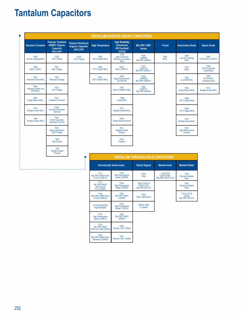
252
TANTALUM SURFACE MOUNT CAPACITORS
Standard TantalumPolymer TantalumKEMET Organic
Capacitor(KO-CAP)
Polymer AluminumOrganic Capacitor
(AO-CAP)High Temperature MIL-PRF CWR
SeriesAutomotive Grade Space GradeFused
High ReliabilityCommercial Off-The-Shelf
(COTS)
TANTALUM THROUGH-HOLE CAPACITORS
Hermetically Sealed Axial Radial Dipped Molded Axial Molded Radial
T110 MIL-PRF-39003 Polar
& T212 (CSR13)
T111 MIL-PRF-39003
Non-Polar &T213 (CSR91)
T140 MIL-PRF-39003 Polar
& T242 (CSR23)
T215 High TemperatureSolder (CSR13)
T216 MIL-PRF-39003
(CSS13) & T256 (CSS33)
T222 MIL-PRF-39003 Polar
Miniature (CSR09)
T210/T240/GR500 High Reliability
T330Precision Molded
Polar
T340 Precision Molded
Polar
T370 & T378(CX06)
MIL-PRF-49137/6
T322/T323(CX01/CX05)
MIL-PRF-49137/1 & 5
T35X Polar
T363 (CX02) &T369 (CX12)
MIL-PRF-49137/2
T368 High Capacitance
T396 & T398 3 Leaded
T225 High TemperatureSolder (CSR09)
T245 High TemperatureSolder (CSR23)
T252 MIL-PRF-39003
(CSR33)
T255 High TemperatureSolder (CSR33)
T262 MIL-PRF-30093
(CSR21)
T550 Polymer 105°C Rated
T551 Polymer 125°C Rated
T489 Low DC Leakage MnO2
T490 High CV MnO2
T491 Industrial Grade MnO2
T495 Surge Robust MnO2
T510 Multiple Anode MnO2
TSM Tantalum Stack MnO2
T494 Industrial Grade Low
ESR MnO2
T498 150°C Rated MnO2
T499 175°C Rated MnO2
T500 200°C Rated MnO2
T493 MnO2 (CWR11)
T495 Surge Robust MnO2
DLA 95158
T513 Multiple Anode MnO2
T497MnO2 (CWR09/19/29)
T419 (CWR19)
MIL-PRF-55365/11
T429 (CWR29)
MIL-PRF-55365/11
T492 (CWR11)
MIL-PRF-55365/8
T540 Single Anode Polymer
T541 Multiple Anode
Polymer
T543 Polymer
A700125°C Rated
T520 105°C Rated
T521 High Voltage
T522 Reduced Leakage
T525 125°C Rated
T527 Facedown Terminal
T528 Low ESL/Facedown
Terminal
T529 Small Case Size
Substrate Terminal
T530 High Capacitance
125°C Rated
T545 High Energy
TSPTantalum Stack
Polymer
T428 High Volumetric
Efficiency FacedownMnO2
T409 (CWR09)
MIL-PRF-55365/4
T489 Low DC Leakage
MnO2
T491MnO2
T494 Low ESR MnO2
T495 Surge Robust MnO2
T498 150°C Rated MnO2
T499 175°C Rated MnO2
T510 Multiple Anode MnO2
T591 High Performance
Polymer
T493 COTS MnO2 (CWR11)
T496 COTS Fail-Safe
Fused MnO2
T497COTS MnO2
(CWR09/19/29)
T496MnO2
T496Fused MnO2
T510 Multiple Anode MnO2
Tantalum Capacitors
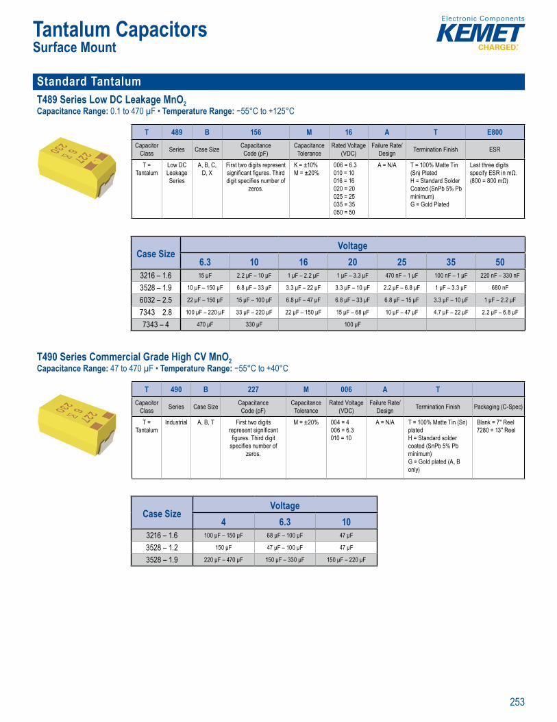
253
Tantalum CapacitorsSurface Mount
Standard TantalumT489 Series Low DC Leakage MnO2Capacitance Range: 0.1 to 470 µF • Temperature Range: −55°C to +125°C
SPICE
Order g Information
T 489 B 156 M 16 A T E800Capacitor
Class Series Case Size Capacitance Code (pF)
Capacitance Tolerance
Rated Voltage (VDC)
Failure Rate/Design Termination Finish ESR
T = Tantalum
Low DC Leakage Series
A, B, C, D, X
First two digits represent signifi cant fi gures. Third digit specifi es number of
zeros.
K = ±10%M = ±20%
006 = 6.3 010 = 10 016 = 16 020 = 20 025 = 25 035 = 35 050 = 50
A = N/A T = 100% Matte Tin (Sn) PlatedH = Standard Solder Coated (SnPb 5% Pb minimum)G = Gold Plated
Last three digits specify ESR in mΩ. (800 = 800 mΩ)
Case SizeVoltage
6.3 10 16 20 25 35 503216 – 1.6 15 μF 2.2 μF – 10 μF 1 μF – 2.2 μF 1 μF – 3.3 μF 470 nF – 1 μF 100 nF – 1 μF 220 nF – 330 nF
3528 – 1.9 10 μF – 150 μF 6.8 μF – 33 μF 3.3 μF – 22 μF 3.3 μF – 10 μF 2.2 μF – 6.8 μF 1 μF – 3.3 μF 680 nF
6032 – 2.5 22 μF – 150 μF 15 μF – 100 μF 6.8 μF – 47 μF 6.8 μF – 33 μF 6.8 μF – 15 μF 3.3 μF – 10 μF 1 μF – 2.2 μF
7343 2.8 100 μF – 220 μF 33 μF – 220 μF 22 μF – 150 μF 15 μF – 68 μF 10 μF – 47 μF 4.7 μF – 22 μF 2.2 μF – 6.8 μF
7343 – 4 470 μF 330 μF 100 μF T490 Series Commercial Grade High CV MnO2 Capacitance Range: 47 to 470 µF • Temperature Range: −55°C to +40°C
pacit Tant
ICE
r a deta led ysis o pecifi a t nu be s, se visi www et com fo a ownloa o ME s P CE tware E og e te i an
Order g Information
T 490 B 227 M 006 A TCapacitor
Class Series Case Size Capacitance Code (pF)
Capacitance Tolerance
Rated Voltage(VDC)
Failure Rate/Design Termination Finish Packaging (C-Spec)
T = Tantalum
Industrial A, B, T First two digits represent signifi cant fi gures. Third digit
specifi es number of zeros.
M = ±20% 004 = 4 006 = 6.3 010 = 10
A = N/A T = 100% Matte Tin (Sn) platedH = Standard solder coated (SnPb 5% Pb minimum)G = Gold plated (A, B only)
Blank = 7" Reel 7280 = 13" Reel
Case SizeVoltage
4 6.3 103216 – 1.6 100 μF – 150 μF 68 μF – 100 μF 47 μF
3528 – 1.2 150 μF 47 μF – 100 μF 47 μF
3528 – 1.9 220 μF – 470 μF 150 μF – 330 μF 150 μF – 220 μF
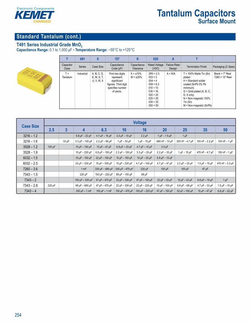
254
Tantalum CapacitorsSurface Mount
Standard Tantalum (cont.)T491 Series Industrial Grade MnO2 Capacitance Range: 0.1 to 1,000 μF • Temperature Range: −55°C to +125°C
T's SP CE s ft
Orderin Information
T 491 X 157 K 020 A TCapacitor
Class Series Case Size Capacitance Code (pF)
Capacitance Tolerance
Rated Voltage (VDC)
Failure Rate/Design Termination Finish Packaging (C-Spec)
T = Tantalum
Industrial A, B, C, D, E, M, S, T, U, V, W, X
First two digits represent signifi cant
fi gures. Third digit specifi es number
of zeros.
K = ±10%M = ±20%
2R5 = 2 5 003 = 3 004 = 4 006 = 6.3 010 = 10 016 = 16 020 = 20 025 = 25 035 = 35 050 = 50
A = N/A T = 100% Matte Tin (Sn) plated H = Standard solder coated (SnPb 5% Pb minimum) G = Gold plated (A, B, C, D, X only) N = Non-magnetic 100% Tin (Sn)M = Non-magnetic (SnPb)
Blank = 7" Reel 7280 = 13" Reel
Case SizeVoltage
2.5 3 4 6.3 10 16 20 25 35 503216 – 1.2 6.8 μF – 22 μF 4.7 μF – 15 μF 3.3 μF – 10 μF 2.2 μF 1 μF – 1 5 μF 1 μF
3216 – 1.6 33 μF 3.3 μF – 100 μF 2.2 μF – 68 μF 1 μF – 33 μF 1 μF – 15 μF 680 nF – 10 μF 330 nF – 4.7 μF 100 nF – 2.2 μF 100 nF – 1 μF
3528 – 1.2 100 μF 15 μF – 100 μF 10 μF – 47 μF 6.8 μF – 33 μF 4.7 μF – 10 μF 3 3 μF
3528 – 1.9 10 μF – 220 μF 6.8 μF – 150 μF 2.2 μF – 100 μF 3.3 μF – 33 μF 2.2 μF – 33 μF 1 μF – 15 μF 470 nF – 4.7 μF 150 nF – 1 μF
6032 – 1.5 33 μF – 150 μF 22 μF – 150 μF 15 μF – 100 μF 10 μF – 33 μF 6.8 μF – 10 μF
6032 – 2.5 22 μF – 330 μF 15 μF – 330 μF 10 μF – 220 μF 4.7 μF – 100 μF 4.7 μF – 47 μF 2.2 μF – 33 μF 1.5 μF – 15 μF 470 nF – 3.3 μF
7260 – 3.6 1 mF 330 μF – 680 μF 330 μF – 470 μF 220 μF 100 μF 100 μF 47 μF
7343 – 1.5 220 μF 150 μF – 220 μF 68 μF – 100 μF 68 μF
7343 – 2 150 μF – 330 μF 47 μF – 470 μF 33 μF – 330 μF 47 μF – 100 μF 22 μF – 33 μF 15 μF – 22 μF 6.8 μF – 10 μF 1 μF
7343 – 2.8 220 μF 68 μF – 680 μF 47 μF – 470 μF 22 μF – 330 μF 22 μF – 220 μF 15 μF – 100 μF 6.8 μF – 68 μF 4.7 μF – 33 μF 1.5 μF – 10 μF
7343 – 4 330 μF – 1 mF 150 μF – 1 mF 150 μF – 470 μF 100 μF – 220 μF 47 μF – 150 μF 33 μF – 100 μF 15 μF – 47 μF 6.8 μF – 22 μF
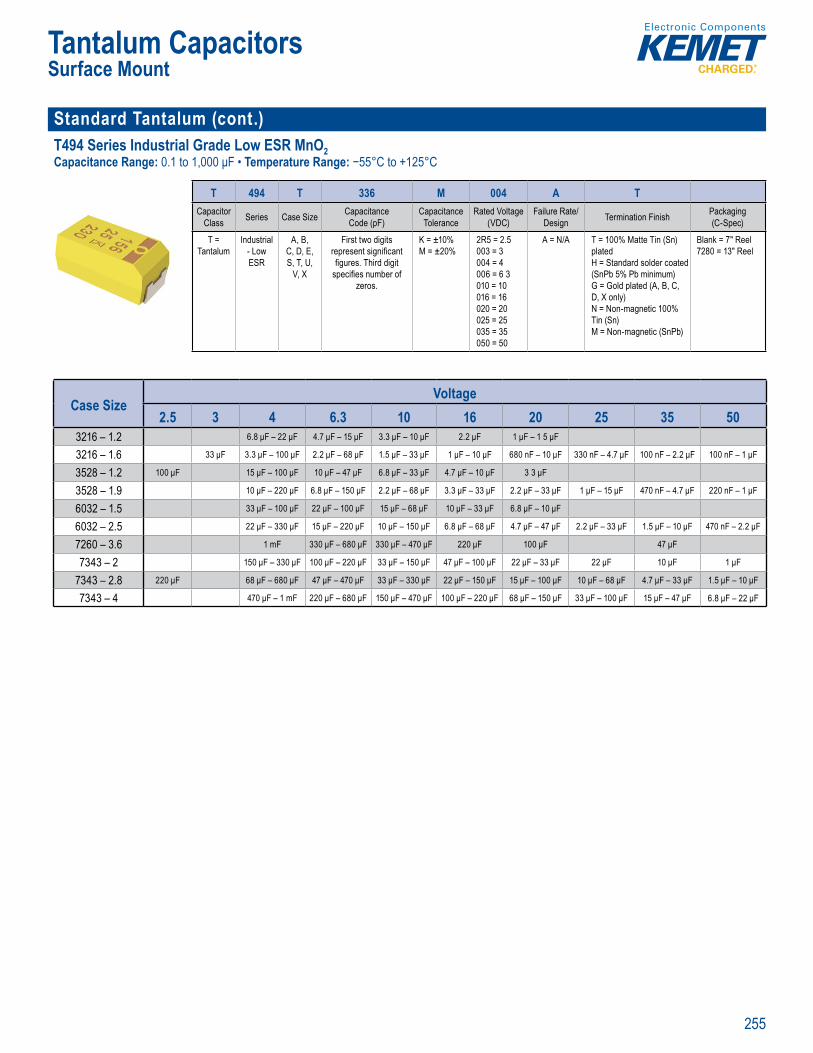
255
Tantalum CapacitorsSurface Mount
Standard Tantalum (cont.)T494 Series Industrial Grade Low ESR MnO2 Capacitance Range: 0.1 to 1,000 μF • Temperature Range: −55°C to +125°C
SPICE
rde in Informat on
T 494 T 336 M 004 A TCapacitor
Class Series Case Size Capacitance Code (pF)
Capacitance Tolerance
Rated Voltage (VDC)
Failure Rate/Design Termination Finish Packaging
(C-Spec)
T = Tantalum
Industrial - Low ESR
A, B, C, D, E, S, T, U,
V, X
First two digits represent signifi cant fi gures. Third digit
specifi es number of zeros.
K = ±10%M = ±20%
2R5 = 2.5 003 = 3 004 = 4 006 = 6 3 010 = 10 016 = 16 020 = 20 025 = 25 035 = 35 050 = 50
A = N/A T = 100% Matte Tin (Sn) platedH = Standard solder coated (SnPb 5% Pb minimum) G = Gold plated (A, B, C, D, X only) N = Non-magnetic 100% Tin (Sn) M = Non-magnetic (SnPb)
Blank = 7" Reel 7280 = 13" Reel
Case SizeVoltage
2.5 3 4 6.3 10 16 20 25 35 503216 – 1.2 6.8 μF – 22 μF 4.7 μF – 15 μF 3.3 μF – 10 μF 2.2 μF 1 μF – 1 5 μF
3216 – 1.6 33 μF 3.3 μF – 100 μF 2.2 μF – 68 μF 1.5 μF – 33 μF 1 μF – 10 μF 680 nF – 10 μF 330 nF – 4.7 μF 100 nF – 2.2 μF 100 nF – 1 μF
3528 – 1.2 100 μF 15 μF – 100 μF 10 μF – 47 μF 6.8 μF – 33 μF 4.7 μF – 10 μF 3 3 μF
3528 – 1.9 10 μF – 220 μF 6.8 μF – 150 μF 2.2 μF – 68 μF 3.3 μF – 33 μF 2.2 μF – 33 μF 1 μF – 15 μF 470 nF – 4.7 μF 220 nF – 1 μF
6032 – 1.5 33 μF – 100 μF 22 μF – 100 μF 15 μF – 68 μF 10 μF – 33 μF 6.8 μF – 10 μF
6032 – 2.5 22 μF – 330 μF 15 μF – 220 μF 10 μF – 150 μF 6.8 μF – 68 μF 4.7 μF – 47 μF 2.2 μF – 33 μF 1.5 μF – 10 μF 470 nF – 2.2 μF
7260 – 3.6 1 mF 330 μF – 680 μF 330 μF – 470 μF 220 μF 100 μF 47 μF
7343 – 2 150 μF – 330 μF 100 μF – 220 μF 33 μF – 150 μF 47 μF – 100 μF 22 μF – 33 μF 22 μF 10 μF 1 μF
7343 – 2.8 220 μF 68 μF – 680 μF 47 μF – 470 μF 33 μF – 330 μF 22 μF – 150 μF 15 μF – 100 μF 10 μF – 68 μF 4.7 μF – 33 μF 1.5 μF – 10 μF
7343 – 4 470 μF – 1 mF 220 μF – 680 μF 150 μF – 470 μF 100 μF – 220 μF 68 μF – 150 μF 33 μF – 100 μF 15 μF – 47 μF 6.8 μF – 22 μF

256
Tantalum CapacitorsSurface Mount
Standard Tantalum (cont.)T495 Series Surge Robust MnO2 Capacitance Range: 0.47 to 1,000 μF • Temperature Range: −55°C to +125°C
' S E t e
Order n formation
T 495 X 107 M 010 A T E045Capacitor
Class Series Case Size
Capacitance Code (pF)
Capacitance Tolerance
Rated Voltage(VDC)
Failure Rate/ Design Termination Finish ESR Packaging
(C-Spec)
T = Tantalum
Surge Robust
Low ESR
A, B, C, D, E, M, T, U, V, X
First two digits represent signifi cant fi gures. Third digit
specifi es number of zeros.
K = ±10%M = ±20%
2R5 = 2.5004 = 4006 = 6 3010 = 10016 = 16020 = 20025 = 25035 = 35050 = 50
A = N/A T = 100% Matte Tin (Sn) platedH = Standard solder coated (SnPb 5% Pb minimum)G = Gold plated (A, B, C, D, X only)
Last three digits specify ESR in mΩ.
(45 = 45 mΩ)
Blank = 7" Reel 7280 = 13" Reel
Case SizeVoltage
2.5 4 6.3 10 16 20 25 35 503216 – 1.6 6.8 μF 2.2 μF – 33 μF 2.2 μF – 22 μF 1 μF – 15 μF 1 μF – 4.7 μF 470 nF – 1.5 μF 330 nF – 1 μF
3528 – 1.2 100 μF 33 μF – 68 μF 10 μF – 33 μF 10 μF – 15 μF 10 μF
3528 – 1.5 100 μF
3528 – 1.9 100 μF – 150 μF 10 μF – 100 μF 4.7 μF – 100 μF 3.3 μF – 33 μF 4.7 μF – 10 μF 2.2 μF – 10 μF 470 nF – 4.7 μF
6032 – 1.5 150 μF 68 μF 47 μF – 100 μF 22 μF – 33 μF
6032 – 2.5 22 μF – 330 μF 6.8 μF – 330 μF 10 μF – 150 μF 6.8 μF – 100 μF 6.8 μF – 33 μF 2.2 μF – 22 μF 2 2 μF – 15 μF 1 μF
7260 – 3.6 1 mF 330 μF – 1 mF 330 μF – 470 μF 220 μF 100 μF – 150 μF 100 μF 33 μF
7343 – 1.5 220 μF 100 μF
7343 – 2 68 μF 47 μF – 470 μF 33 μF – 220 μF 68 μF – 100 μF 22 μF 15 μF 6.8 μF – 10 μF
7343 – 2.8 220 μF – 470 μF 100 μF – 470 μF 68 μF – 470 μF 47 μF – 330 μF 33 μF – 220 μF 15 μF – 68 μF 10 μF – 68 μF 4.7 μF – 33 μF 2.2 μF – 6.8 μF
7343 – 4 1 mF 470 μF – 1 mF 150 μF – 1 mF 68 μF – 470 μF 68 μF – 220 μF 33 μF – 100 μF 15 μF – 100 μF 6.8 μF – 47 μF 4.7 μF – 15 μF
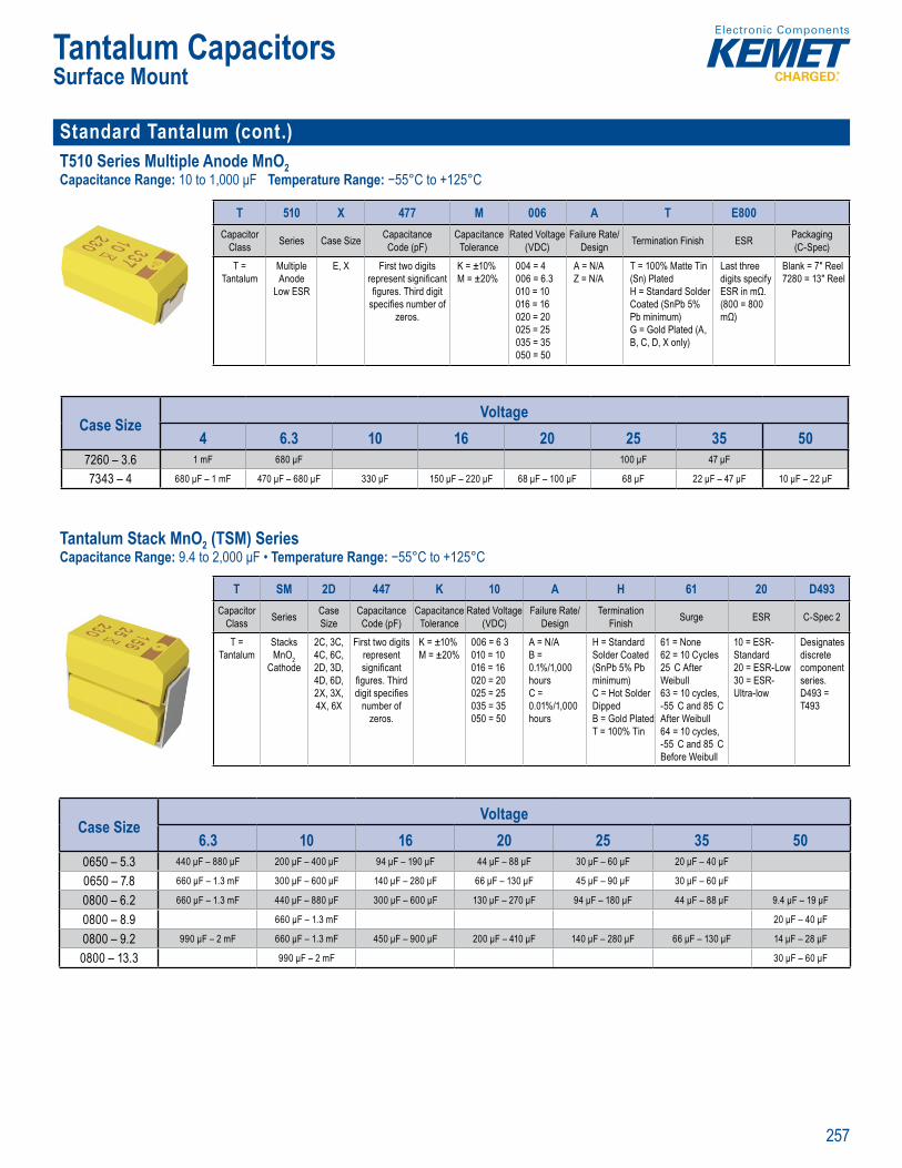
257
Tantalum CapacitorsSurface Mount
Standard Tantalum (cont.)T510 Series Multiple Anode MnO2 Capacitance Range: 10 to 1,000 μF Temperature Range: −55°C to +125°C
SPICE
Orde in Information
T 510 X 477 M 006 A T E800Capacitor
Class Series Case Size Capacitance Code (pF)
Capacitance Tolerance
Rated Voltage (VDC)
Failure Rate/Design Termination Finish ESR Packaging
(C-Spec)
T = Tantalum
Multiple Anode
Low ESR
E, X First two digits represent signifi cant fi gures. Third digit
specifi es number of zeros.
K = ±10%M = ±20%
004 = 4006 = 6.3 010 = 10 016 = 16 020 = 20 025 = 25035 = 35 050 = 50
A = N/AZ = N/A
T = 100% Matte Tin (Sn) Plated H = Standard Solder Coated (SnPb 5% Pb minimum) G = Gold Plated (A, B, C, D, X only)
Last three digits specify ESR in mΩ. (800 = 800 mΩ)
Blank = 7" Reel7280 = 13" Reel
Case SizeVoltage
4 6.3 10 16 20 25 35 507260 – 3.6 1 mF 680 μF 100 μF 47 μF
7343 – 4 680 μF – 1 mF 470 μF – 680 μF 330 μF 150 μF – 220 μF 68 μF – 100 μF 68 μF 22 μF – 47 μF 10 μF – 22 μF
Tantalum Stack MnO2 (TSM) SeriesCapacitance Range: 9.4 to 2,000 μF • Temperature Range: −55°C to +125°C
analy down ET s The E SPI E o f eew de to id es n neers a th p e of hese c or ov r
rde in Informat on
T SM 2D 447 K 10 A H 61 20 D493Capacitor
Class Series CaseSize
CapacitanceCode (pF)
Capacitance Tolerance
Rated Voltage (VDC)
Failure Rate/Design
Termination Finish Surge ESR C-Spec 2
T = Tantalum
Stacks MnO2
Cathode
2C, 3C, 4C, 6C, 2D, 3D, 4D, 6D, 2X, 3X, 4X, 6X
First two digits represent signifi cant
fi gures. Third digit specifi es
number of zeros.
K = ±10%M = ±20%
006 = 6 3010 = 10016 = 16020 = 20025 = 25035 = 35050 = 50
A = N/AB = 0.1%/1,000 hours C = 0.01%/1,000 hours
H = Standard Solder Coated (SnPb 5% Pb minimum) C = Hot Solder Dipped B = Gold Plated T = 100% Tin
61 = None62 = 10 Cycles 25 C After Weibull 63 = 10 cycles, -55 C and 85 C After Weibull 64 = 10 cycles,-55 C and 85 C Before Weibull
10 = ESR-Standard 20 = ESR-Low30 = ESR-Ultra-low
Designates discrete component series.D493 = T493
Case SizeVoltage
6.3 10 16 20 25 35 500650 – 5.3 440 μF – 880 μF 200 μF – 400 μF 94 μF – 190 μF 44 μF – 88 μF 30 μF – 60 μF 20 μF – 40 μF
0650 – 7.8 660 μF – 1.3 mF 300 μF – 600 μF 140 μF – 280 μF 66 μF – 130 μF 45 μF – 90 μF 30 μF – 60 μF
0800 – 6.2 660 μF – 1.3 mF 440 μF – 880 μF 300 μF – 600 μF 130 μF – 270 μF 94 μF – 180 μF 44 μF – 88 μF 9.4 μF – 19 μF
0800 – 8.9 660 μF – 1.3 mF 20 μF – 40 μF
0800 – 9.2 990 μF – 2 mF 660 μF – 1.3 mF 450 μF – 900 μF 200 μF – 410 μF 140 μF – 280 μF 66 μF – 130 μF 14 μF – 28 μF
0800 – 13.3 990 μF – 2 mF 30 μF – 60 μF
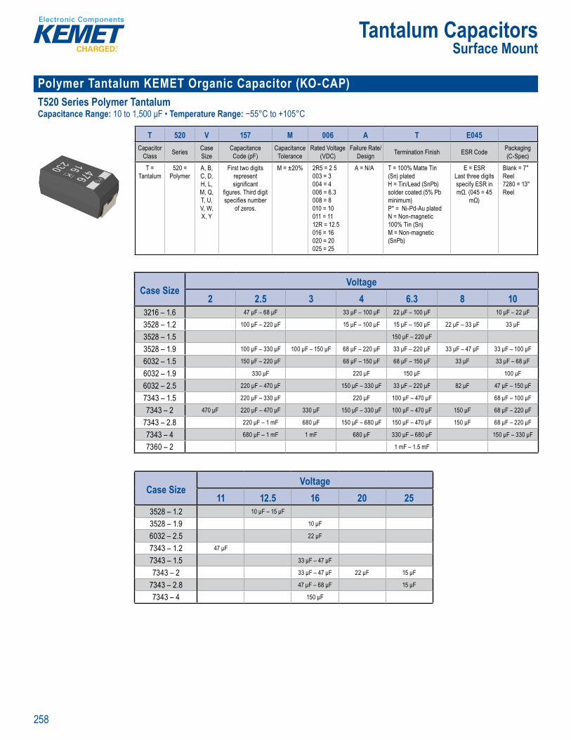
258
Tantalum CapacitorsSurface Mount
Polymer Tantalum KEMET Organic Capacitor (KO-CAP)T520 Series Polymer Tantalum Capacitance Range: 10 to 1,500 μF • Temperature Range: −55°C to +105°C
MET Organic Ca cit ndT 0 Low ES P l r ect ol t c 5 VDC
Orde in Information
T 520 V 157 M 006 A T E045Capacitor
Class Series Case Size
Capacitance Code (pF)
Capacitance Tolerance
Rated Voltage (VDC)
Failure Rate/Design Termination Finish ESR Code Packaging
(C-Spec)
T = Tantalum
520 = Polymer
A, B, C, D, H, L, M, Q, T, U, V, W, X, Y
First two digits represent signifi cant
fi gures. Third digit specifi es number
of zeros.
M = ±20% 2R5 = 2 5 003 = 3 004 = 4 006 = 6.3 008 = 8 010 = 10 011 = 11 12R = 12.5 016 = 16 020 = 20 025 = 25
A = N/A T = 100% Matte Tin (Sn) platedH = Tin/Lead (SnPb) solder coated (5% Pb minimum)P* = Ni-Pd-Au plated N = Non-magnetic 100% Tin (Sn) M = Non-magnetic (SnPb)
E = ESR Last three digits specify ESR in mΩ. (045 = 45
mΩ)
Blank = 7" Reel 7280 = 13" Reel
Case SizeVoltage
2 2.5 3 4 6.3 8 103216 – 1.6 47 μF – 68 μF 33 μF – 100 μF 22 μF – 100 μF 10 μF – 22 μF
3528 – 1.2 100 μF – 220 μF 15 μF – 100 μF 15 μF – 150 μF 22 μF – 33 μF 33 μF
3528 – 1.5 150 μF – 220 μF
3528 – 1.9 100 μF – 330 μF 100 μF – 150 μF 68 μF – 220 μF 33 μF – 220 μF 33 μF – 47 μF 33 μF – 100 μF
6032 – 1.5 150 μF – 220 μF 68 μF – 150 μF 68 μF – 150 μF 33 μF 33 μF – 68 μF
6032 – 1.9 330 μF 220 μF 150 μF 100 μF
6032 – 2.5 220 μF – 470 μF 150 μF – 330 μF 33 μF – 220 μF 82 μF 47 μF – 150 μF
7343 – 1.5 220 μF – 330 μF 220 μF 100 μF – 470 μF 68 μF – 100 μF
7343 – 2 470 μF 220 μF – 470 μF 330 μF 150 μF – 330 μF 100 μF – 470 μF 150 μF 68 μF – 220 μF
7343 – 2.8 220 μF – 1 mF 680 μF 150 μF – 680 μF 150 μF – 470 μF 150 μF 68 μF – 220 μF
7343 – 4 680 μF – 1 mF 1 mF 680 μF 330 μF – 680 μF 150 μF – 330 μF
7360 – 2 1 mF – 1.5 mF
Case SizeVoltage
11 12.5 16 20 253528 – 1.2 10 μF – 15 μF
3528 – 1.9 10 μF
6032 – 2.5 22 μF
7343 – 1.2 47 μF
7343 – 1.5 33 μF – 47 μF
7343 – 2 33 μF – 47 μF 22 μF 15 μF
7343 – 2.8 47 μF – 68 μF 15 μF
7343 – 4 150 μF
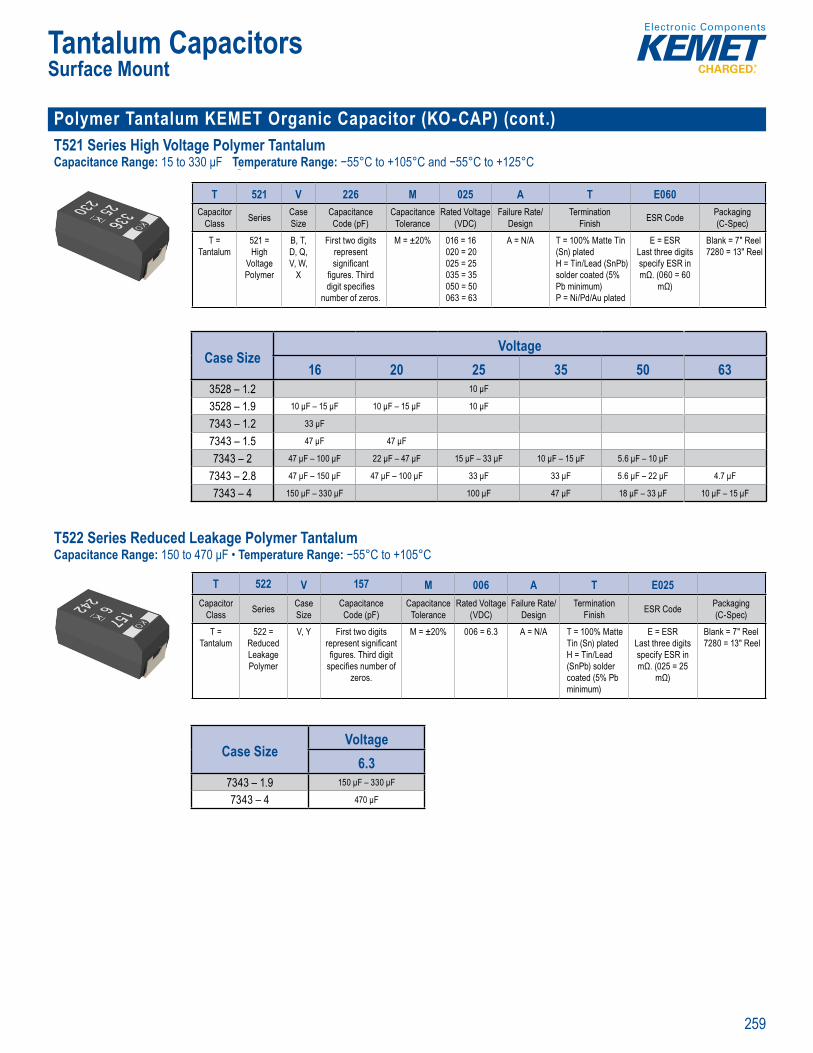
259
Tantalum CapacitorsSurface Mount
Polymer Tantalum KEMET Organic Capacitor (KO-CAP) (cont.)T521 Series High Voltage Polymer Tantalum Capacitance Range: 15 to 330 μF Temperature Range: −55°C to +105°C and −55°C to +125°C
K MET Organic Ca acito (K C P ) ndus ia r E
Orde i g Info mation
T 521 V 226 M 025 A T E060Capacitor
Class Series Case Size
Capacitance Code (pF)
Capacitance Tolerance
Rated Voltage (VDC)
Failure Rate/Design
Termination Finish ESR Code Packaging
(C-Spec)
T = Tantalum
521 = High
Voltage Polymer
B, T, D, Q, V, W,
X
First two digits represent signifi cant
fi gures. Third digit specifi es
number of zeros.
M = ±20% 016 = 16 020 = 20 025 = 25 035 = 35 050 = 50 063 = 63
A = N/A T = 100% Matte Tin (Sn) platedH = Tin/Lead (SnPb) solder coated (5% Pb minimum)P = Ni/Pd/Au plated
E = ESRLast three digits specify ESR in mΩ. (060 = 60
mΩ)
Blank = 7" Reel 7280 = 13" Reel
Case SizeVoltage
16 20 25 35 50 633528 – 1.2 10 μF
3528 – 1.9 10 μF – 15 μF 10 μF – 15 μF 10 μF
7343 – 1.2 33 μF
7343 – 1.5 47 μF 47 μF
7343 – 2 47 μF – 100 μF 22 μF – 47 μF 15 μF – 33 μF 10 μF – 15 μF 5.6 μF – 10 μF
7343 – 2.8 47 μF – 150 μF 47 μF – 100 μF 33 μF 33 μF 5.6 μF – 22 μF 4.7 μF
7343 – 4 150 μF – 330 μF 100 μF 47 μF 18 μF – 33 μF 10 μF – 15 μF
T522 Series Reduced Leakage Polymer Tantalum Capacitance Range: 150 to 470 μF • Temperature Range: −55°C to +105°C
Ord ri g Information
T 522 V 157 M 006 A T E025Capacitor
Class Series Case Size
Capacitance Code (pF)
Capacitance Tolerance
Rated Voltage (VDC)
Failure Rate/Design
Termination Finish ESR Code Packaging
(C-Spec)
T = Tantalum
522 = Reduced Leakage Polymer
V, Y First two digits represent signifi cant fi gures. Third digit
specifi es number of zeros.
M = ±20% 006 = 6.3 A = N/A T = 100% Matte Tin (Sn) platedH = Tin/Lead (SnPb) solder coated (5% Pb minimum)
E = ESRLast three digits specify ESR in mΩ. (025 = 25
mΩ)
Blank = 7" Reel 7280 = 13" Reel
Case SizeVoltage
6.37343 – 1.9 150 μF – 330 μF
7343 – 4 470 μF
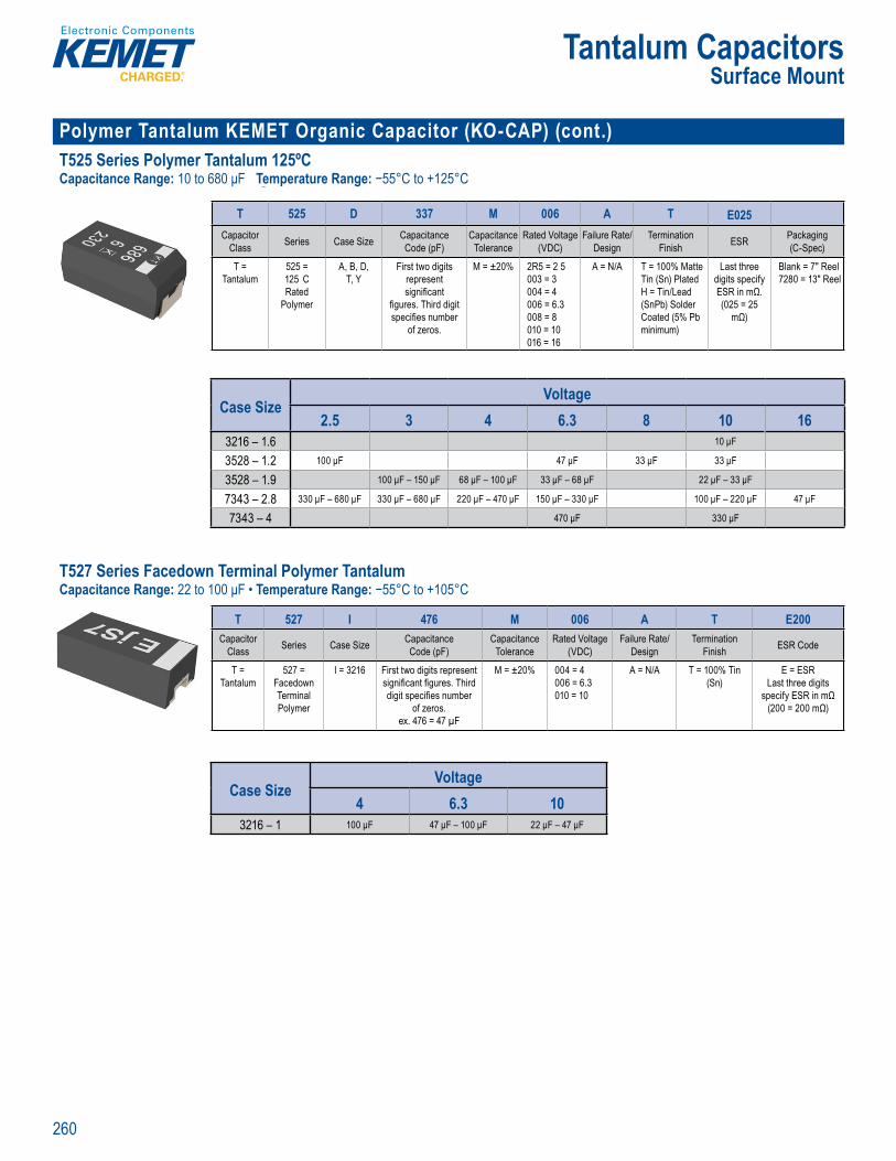
260
Tantalum CapacitorsSurface Mount
Polymer Tantalum KEMET Organic Capacitor (KO-CAP) (cont.) T525 Series Polymer Tantalum 125ºCCapacitance Range: 10 to 680 μF Temperature Range: −55°C to +125°C
K MET Organic Ca acito (K C P ) ndus ia 125
Orde i g Info mation
T 525 D 337 M 006 A T E025Capacitor
Class Series Case Size Capacitance Code (pF)
Capacitance Tolerance
Rated Voltage (VDC)
Failure Rate/Design
TerminationFinish ESR Packaging
(C-Spec)
T = Tantalum
525 = 125 C Rated
Polymer
A, B, D, T, Y
First two digits represent signifi cant
fi gures. Third digit specifi es number
of zeros.
M = ±20% 2R5 = 2 5 003 = 3 004 = 4 006 = 6.3 008 = 8 010 = 10 016 = 16
A = N/A T = 100% Matte Tin (Sn) PlatedH = Tin/Lead (SnPb) Solder Coated (5% Pb minimum)
Last three digits specify ESR in mΩ. (025 = 25
mΩ)
Blank = 7" Reel 7280 = 13" Reel
Case SizeVoltage
2.5 3 4 6.3 8 10 163216 – 1.6 10 μF
3528 – 1.2 100 μF 47 μF 33 μF 33 μF
3528 – 1.9 100 μF – 150 μF 68 μF – 100 μF 33 μF – 68 μF 22 μF – 33 μF
7343 – 2.8 330 μF – 680 μF 330 μF – 680 μF 220 μF – 470 μF 150 μF – 330 μF 100 μF – 220 μF 47 μF
7343 – 4 470 μF 330 μF
T527 Series Facedown Terminal Polymer Tantalum Capacitance Range: 22 to 100 μF • Temperature Range: −55°C to +105°C
Or e g In mat on
T 527 I 476 M 006 A T E200Capacitor
Class Series Case Size Capacitance Code (pF)
Capacitance Tolerance
Rated Voltage (VDC)
Failure Rate/ Design
TerminationFinish ESR Code
T = Tantalum
527 = Facedown Terminal Polymer
I = 3216 First two digits represent signifi cant fi gures. Third digit specifi es number
of zeros.ex. 476 = 47 µF
M = ±20% 004 = 4 006 = 6.3 010 = 10
A = N/A T = 100% Tin (Sn)
E = ESR Last three digits
specify ESR in mΩ (200 = 200 mΩ)
Case SizeVoltage
4 6.3 103216 – 1 100 μF 47 μF – 100 μF 22 μF – 47 μF

261
Tantalum CapacitorsSurface Mount
Polymer Tantalum KEMET Organic Capacitor (KO-CAP) (cont.)T528 Series Low ESL Facedown Terminal Polymer Tantalum Capacitance Range: 33 to 470 μF Temperature Range: −55°C to +105°C
K MET Organic Ca acito (K C P ) Min a u ctr U
Orde i g Info mation
T 528 Z 337 M 2R5 A T E009Capacitor
Class Series Case Size Capacitance Code (pF)
Capacitance Tolerance
Rated Voltage (VDC)
Failure Rate/Design
Termination Finish ESR Code Packaging
(C-Spec)
T = Tantalum
528 = Low ESL
Facedown Terminal Polymer
B = 3528-21W = 7343-15Z = 7343-17
First two digits represent signifi cant
fi gures. Third digit specifi es number
of zeros.
M = ±20% 002 = 2 2R5 = 2 5 004 = 4 006 = 6.3
A = N/A T = 100% Matte Tin (Sn) platedP = Ni-Pd-Au plated
E = ESR Last three
digits specify ESR in mΩ
(009 = 9 mΩ)
Blank = 7" Reel 7280 = 13" Reel
Case SizeVoltage
2 2.5 4 6.33528 – 2 270 μF
7343 – 1.5 330 μF
7343 – 1.7 220 μF – 470 μF 220 μF – 330 μF 150 μF – 220 μF
T529 Series Small Case Size Substrate Terminal Polymer Tantalum Capacitance Range: 22 to 150 μF Temperature Range: −55°C to +105°C
Orderi g Info mation
T 529 P 476 M 006 A A E200Capacitor
Class Series Case Size Capacitance Code (pF)
Capacitance Tolerance
Rated Voltage (VDC)
Failure Rate/ Design
TerminationFinish ESR Code
T = Tantalum
529 = Substrate Terminal Polymer
P = 2012-10I = 3216-10
First two digits represent signifi cant fi gures. Third digit
specifi es number of zeros.
ex. 476 = 47 µF
M = ±20% 006 = 6.3010 = 10
A = N/A A = Ni - Au E = ESR Last three digits
specify ESR in mΩ (200 = 200 mΩ)
Case SizeVoltage
6.3 102012 – 1 22 μF – 47 μF 22 μF – 47 μF
3216 – 1 150 μF
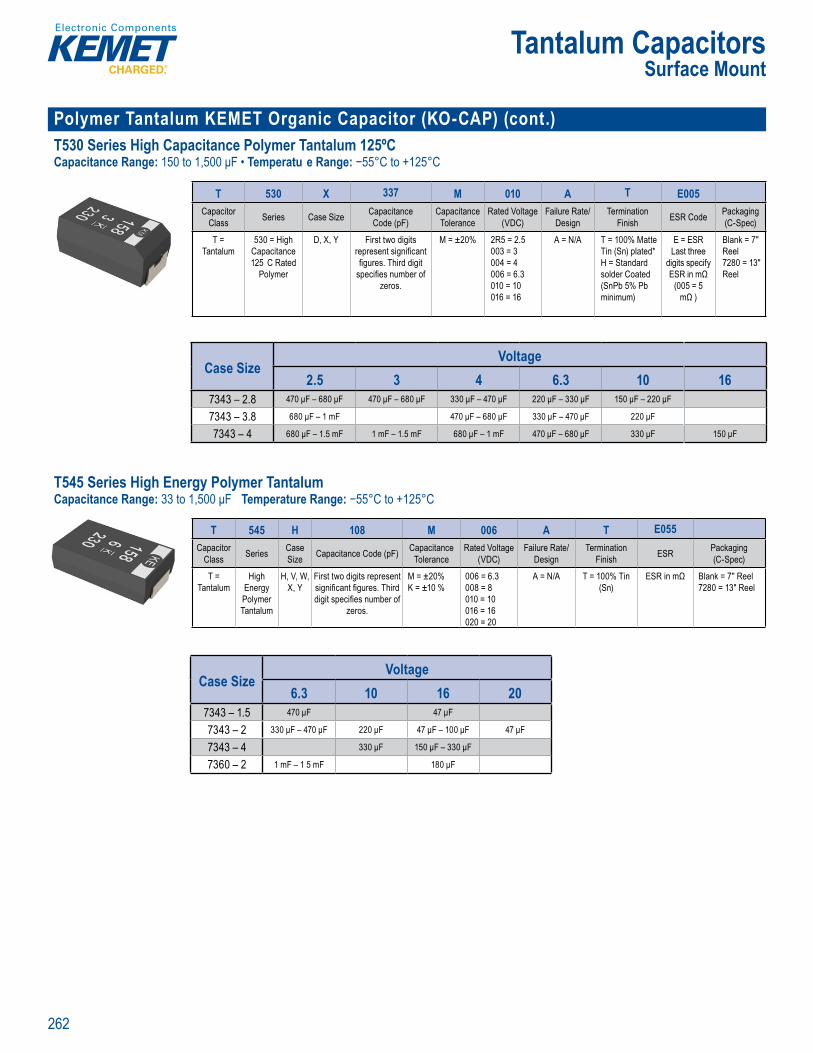
262
Tantalum CapacitorsSurface Mount
Polymer Tantalum KEMET Organic Capacitor (KO-CAP) (cont.)T530 Series High Capacitance Polymer Tantalum 125ºCCapacitance Range: 150 to 1,500 μF • Temperatu e Range: −55°C to +125°C
' S E t
q n y, temp t , D
Orde in n ormation
T 530 X 337 M 010 A T E005Capacitor
Class Series Case Size Capacitance Code (pF)
Capacitance Tolerance
Rated Voltage (VDC)
Failure Rate/Design
Termination Finish ESR Code Packaging
(C-Spec)
T = Tantalum
530 = High Capacitance 125 C Rated
Polymer
D, X, Y First two digits represent signifi cant fi gures. Third digit
specifi es number of zeros.
M = ±20% 2R5 = 2.5003 = 3 004 = 4 006 = 6.3 010 = 10016 = 16
A = N/A T = 100% Matte Tin (Sn) plated*H = Standard solder Coated (SnPb 5% Pb minimum)
E = ESR Last three
digits specify ESR in mΩ
(005 = 5 mΩ )
Blank = 7" Reel 7280 = 13" Reel
Case SizeVoltage
2.5 3 4 6.3 10 167343 – 2.8 470 μF – 680 μF 470 μF – 680 μF 330 μF – 470 μF 220 μF – 330 μF 150 μF – 220 μF
7343 – 3.8 680 μF – 1 mF 470 μF – 680 μF 330 μF – 470 μF 220 μF
7343 – 4 680 μF – 1.5 mF 1 mF – 1.5 mF 680 μF – 1 mF 470 μF – 680 μF 330 μF 150 μF
T545 Series High Energy Polymer Tantalum Capacitance Range: 33 to 1,500 μF Temperature Range: −55°C to +125°C
Orde in Information
T 545 H 108 M 006 A T E055Capacitor
Class Series Case Size Capacitance Code (pF) Capacitance
ToleranceRated Voltage
(VDC)Failure Rate/
DesignTermination
Finish ESR Packaging (C-Spec)
T = Tantalum
High Energy Polymer Tantalum
H, V, W, X, Y
First two digits represent signifi cant fi gures. Third digit specifi es number of
zeros.
M = ±20%K = ±10 %
006 = 6.3 008 = 8 010 = 10 016 = 16 020 = 20
A = N/A T = 100% Tin (Sn)
ESR in mΩ Blank = 7" Reel 7280 = 13" Reel
Case SizeVoltage
6.3 10 16 207343 – 1.5 470 μF 47 μF
7343 – 2 330 μF – 470 μF 220 μF 47 μF – 100 μF 47 μF
7343 – 4 330 μF 150 μF – 330 μF
7360 – 2 1 mF – 1 5 mF 180 μF
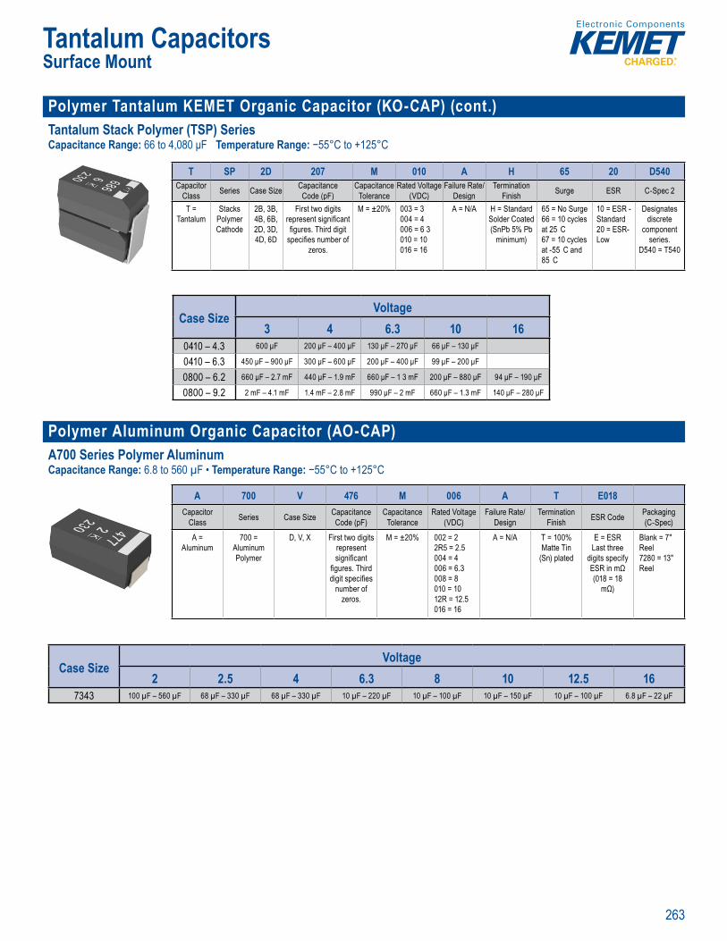
263
Tantalum CapacitorsSurface Mount
Polymer Tantalum KEMET Organic Capacitor (KO-CAP) (cont.)Tantalum Stack Polymer (TSP) SeriesCapacitance Range: 66 to 4,080 μF Temperature Range: −55°C to +125°C
SPICE
q n y, temp t , D
Orderin Information
T SP 2D 207 M 010 A H 65 20 D540Capacitor
Class Series Case Size CapacitanceCode (pF)
Capacitance Tolerance
Rated Voltage (VDC)
Failure Rate/Design
Termination Finish Surge ESR C-Spec 2
T = Tantalum
Stacks Polymer Cathode
2B, 3B,4B, 6B, 2D, 3D,4D, 6D
First two digits represent signifi cant fi gures. Third digit
specifi es number of zeros.
M = ±20% 003 = 3004 = 4006 = 6 3010 = 10016 = 16
A = N/A H = Standard Solder Coated (SnPb 5% Pb
minimum)
65 = No Surge 66 = 10 cycles at 25 C 67 = 10 cycles at -55 C and 85 C
10 = ESR - Standard20 = ESR-Low
Designates discrete
component series.
D540 = T540
Case SizeVoltage
3 4 6.3 10 160410 – 4.3 600 μF 200 μF – 400 μF 130 μF – 270 μF 66 μF – 130 μF
0410 – 6.3 450 μF – 900 μF 300 μF – 600 μF 200 μF – 400 μF 99 μF – 200 μF
0800 – 6.2 660 μF – 2.7 mF 440 μF – 1.9 mF 660 μF – 1 3 mF 200 μF – 880 μF 94 μF – 190 μF
0800 – 9.2 2 mF – 4.1 mF 1.4 mF – 2.8 mF 990 μF – 2 mF 660 μF – 1.3 mF 140 μF – 280 μF
Polymer Aluminum Organic Capacitor (AO-CAP)A700 Series Polymer AluminumCapacitance Range: 6.8 to 560 µF • Temperature Range: −55°C to +125°C
A70 Polymer A uminu 2 1 VDC
Orderi g Info mat n
A 700 V 476 M 006 A T E018Capacitor
Class Series Case Size Capacitance Code (pF)
Capacitance Tolerance
Rated Voltage (VDC)
Failure Rate/Design
Termination Finish ESR Code Packaging
(C-Spec)
A = Aluminum
700 = Aluminum Polymer
D, V, X First two digits represent signifi cant
fi gures. Third digit specifi es
number of zeros.
M = ±20% 002 = 2 2R5 = 2.5 004 = 4 006 = 6.3 008 = 8 010 = 10 12R = 12.5 016 = 16
A = N/A T = 100% Matte Tin
(Sn) plated
E = ESR Last three
digits specify ESR in mΩ (018 = 18
mΩ)
Blank = 7" Reel 7280 = 13" Reel
Case SizeVoltage
2 2.5 4 6.3 8 10 12.5 167343 100 µF – 560 µF 68 µF – 330 µF 68 µF – 330 µF 10 µF – 220 µF 10 µF – 100 µF 10 µF – 150 µF 10 µF – 100 µF 6.8 µF – 22 µF

264
Tantalum CapacitorsSurface Mount
High TemperatureT498 Series Automotive Grade MnO2 150ºCCapacitance Range: 0.1 to 220 μF • Temperature Range: −55°C to +150°C
s SP CE softw re The
Order g nf mation
T 498 X 227 M 010 A T E500Capacitor
Class Series Case Size
Capacitance Code (pF)
Capacitance Tolerance
Rated Voltage (VDC)
Failure Rate/Design Termination Finish ESR Packaging
(C-Spec)
T = Tantalum
High Temperature
150ºC
A, B, C, D,
X
First two digits represent signifi cant fi gures. Third digit
specifi es number of zeros.
K = ±10%M = ±20%
004 = 4006 = 6.3 010 = 10 015 = 15 020 = 20025 = 25 035 = 35 050 = 50
A = N/A T = 100% Matte Tin (Sn) plated* G = Gold platedH = Standard solder coated (SnPb 5% Pb minimum)
E = ESR Last three
digits specify
ESR in mΩ (500 = 500
mΩ)
Blank = 7" Reel7280 = 13" Reel
Case SizeVoltage
4 6.3 10 16 20 25 35 503216 – 1.6 2 2 μF – 10 μF 1.5 μF – 6.8 μF 1 μF – 6.8 μF 680 nF – 1.5 μF 470 nF – 1 μF 100 nF – 1 μF 100 nF
3528 – 1.9 6.8 μF – 33 μF 4.7 μF – 22 μF 3 3 μF – 10 μF 2.2 μF – 4.7 μF 1.5 μF – 2 2 μF 470 nF – 1 μF 150 nF – 330 nF
6032 – 2.5 15 μF – 68 μF 10 μF – 47 μF 6.8 μF – 47 μF 4.7 μF – 15 μF 3 3 μF – 10 μF 1.5 μF – 4.7 μF 470 nF – 1 μF
7343 – 2.8 150 μF 47 μF – 150 μF 33 μF – 100 μF 22 μF – 68 μF 15 μF – 33 μF 6.8 μF – 33 μF 4.7 μF – 22 μF 1.5 μF – 10 μF
7343 – 4 150 μF – 220 μF 15 μF – 47 μF 6.8 μF – 10 μF
T499 Series Automotive Grade MnO2 175ºCCapacitance Range: 0.15 to 220 μF • Temperature Range: −55°C to +175°C
ac M Aut
tai e nalys peci c pa t n s, please vi . emet com ree downloa EME s I tware. he
rde in Informa ion
T 499 X 227 M 010 A T E500Capacitor
Class Series Case Size
Capacitance Code (pF)
Capacitance Tolerance
Rated Voltage (VDC)
Failure Rate/Design
Termination Finish ESR Packaging
(C-Spec)
T = Tantalum
High Temperature
175ºC
A, B, C, D,
X
First two digits represent signifi cant
fi gures. Third digit specifi es number
of zeros.
K = ±10%M = ±20%
006 = 6 3010 = 10015 = 15020 = 20025 = 25035 = 35050 = 50
A = N/A T = 100% Matte Tin (Sn) platedG = Gold platedH = Standard solder coated (SnPb 5% Pb minimum)
E = ESR Last three digits
specify ESR in mΩ (500 =
500 mΩ)
Blank = 7" Reel7280 = 13" Reel
Case SizeVoltage
6.3 10 16 20 25 35 503216 – 1.6 1.5 μF – 6.8 μF 1 μF – 6.8 μF 680 nF – 1.5 μF 470 nF – 1 5 μF 150 nF – 1 μF
3528 – 1.9 10 μF – 33 μF 4.7 μF – 22 μF 3.3 μF – 10 μF 2.2 μF – 4.7 μF 2 2 μF 470 nF – 1 μF
6032 – 2.5 22 μF – 47 μF 10 μF – 33 μF 6.8 μF – 22 μF 4.7 μF – 15 μF 3.3 μF – 10 μF 1.5 μF – 4.7 μF
7343 – 2.8 100 μF 33 μF – 100 μF 22 μF – 47 μF 15 μF – 22 μF 6.8 μF – 33 μF 6.8 μF – 10 μF 3 3 μF – 10 μF
7343 – 4 220 μF 100 μF 22 μF – 33 μF
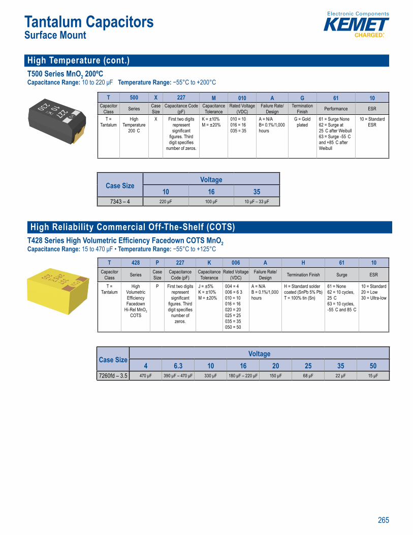
265
Tantalum CapacitorsSurface Mount
High Temperature (cont.)T500 Series MnO2 200ºCCapacitance Range: 10 to 220 μF Temperature Range: −55°C to +200°C
t a e T 0 S
Orderi g Info mation
T 500 X 227 M 010 A G 61 10Capacitor
Class Series Case Size
Capacitance Code (pF)
Capacitance Tolerance
Rated Voltage (VDC)
Failure Rate/ Design
Termination Finish Performance ESR
T = Tantalum
High Temperature
200 C
X First two digits represent signifi cant
fi gures. Third digit specifi es
number of zeros.
K = ±10% M = ±20%
010 = 10 016 = 16 035 = 35
A = N/AB= 0.1%/1,000 hours
G = Gold plated
61 = Surge None62 = Surge at 25 C after Weibull63 = Surge -55 C and +85 C after Weibull
10 = Standard ESR
Case SizeVoltage
10 16 357343 – 4 220 μF 100 μF 10 μF – 33 μF
High Reliability Commercial Off-The-Shelf (COTS)
T428 Series High Volumetric Efficiency Facedown COTS MnO2 Capacitance Range: 15 to 470 μF • Temperature Range: −55°C to +125°C
CE
i f
Or e i g Info ma on
T 428 P 227 K 006 A H 61 10Capacitor
Class Series Case Size
Capacitance Code (pF)
Capacitance Tolerance
Rated Voltage (VDC)
Failure Rate/Design Termination Finish Surge ESR
T = Tantalum
High Volumetric Effi ciency Facedown
Hi-Rel MnO2 COTS
P First two digits represent signifi cant
fi gures. Third digit specifi es
number of zeros.
J = ±5% K = ±10% M = ±20%
004 = 4006 = 6 3010 = 10 016 = 16 020 = 20 025 = 25 035 = 35 050 = 50
A = N/AB = 0.1%/1,000 hours
H = Standard solder coated (SnPb 5% Pb)T = 100% tin (Sn)
61 = None 62 = 10 cycles, 25 C 63 = 10 cycles, -55 C and 85 C
10 = Standard 20 = Low 30 = Ultra-low
Case SizeVoltage
4 6.3 10 16 20 25 35 507260fd – 3.5 470 μF 390 μF – 470 μF 330 μF 180 μF – 220 μF 150 μF 68 μF 22 μF 15 μF
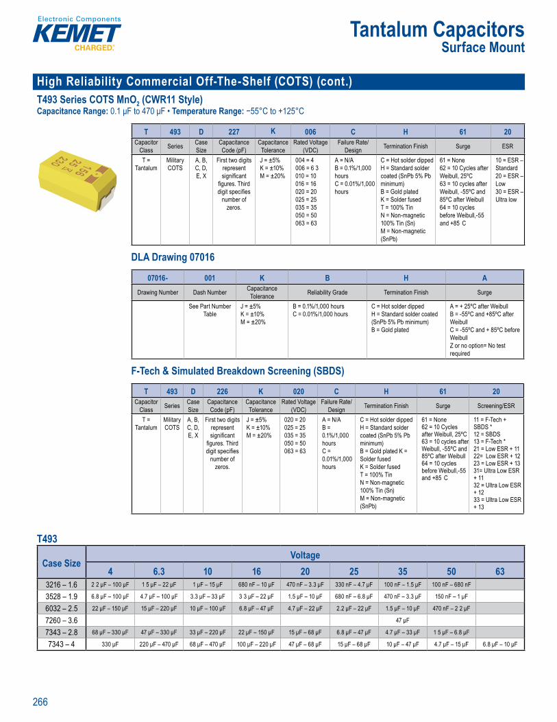
266
Tantalum CapacitorsSurface Mount
High Reliability Commercial Off-The-Shelf (COTS) (cont.)T493 Series COTS MnO2 (CWR11 Style)Capacitance Range: 0.1 μF to 470 μF • Temperature Range: −55°C to +125°C
f y e tu e, ipp e, a bi on t ons.
Order ng Information
T 493 D 227 K 006 C H 61 20Capacitor
Class Series Case Size
Capacitance Code (pF)
Capacitance Tolerance
Rated Voltage (VDC)
Failure Rate/Design Termination Finish Surge ESR
T = Tantalum
Military COTS
A, B, C, D, E, X
First two digits represent signifi cant
fi gures. Third digit specifi es
number of zeros.
J = ±5%K = ±10%M = ±20%
004 = 4006 = 6 3010 = 10016 = 16020 = 20025 = 25035 = 35050 = 50063 = 63
A = N/AB = 0.1%/1,000 hours C = 0.01%/1,000 hours
C = Hot solder dipped H = Standard solder coated (SnPb 5% Pb minimum)B = Gold platedK = Solder fusedT = 100% TinN = Non-magnetic 100% Tin (Sn)M = Non-magnetic (SnPb)
61 = None 62 = 10 Cycles after Weibull, 25ºC 63 = 10 cycles after Weibull, -55ºC and 85ºC after Weibull64 = 10 cycles before Weibull,-55 and +85 C
10 = ESR – Standard20 = ESR – Low30 = ESR – Ultra low
DLA Drawing 07016
Orde ng Information
07016- 001 K B H ADrawing Number Dash Number Capacitance
Tolerance Reliability Grade Termination Finish Surge
See Part Number Table
J = ±5%K = ±10%M = ±20%
B = 0.1%/1,000 hours C = 0.01%/1,000 hours
C = Hot solder dipped H = Standard solder coated (SnPb 5% Pb minimum)B = Gold plated
A = + 25ºC after WeibullB = -55ºC and +85ºC after WeibullC = -55ºC and + 85ºC before Weibull Z or no option= No test required
F-Tech & Simulated Breakdown Screening (SBDS)
– High Rel a (COT )
7016- 001
Tab e
±10% ±20%
01%/1,000 hour
tandard solder coa
B Gold plated
nd +8
C 55ºC and + 85ºC be We bul Z or no req ired
Ordering nformat on – F- ech & imulated B eakdow
T 493 D 226 K 020 C H 61 20Capacitor
Class Series Case Size
Capacitance Code (pF)
Capacitance Tolerance
Rated Voltage (VDC)
Failure Rate/ Design Termination Finish Surge Screening/ESR
T = Tantalum
Military COTS
A, B, C, D, E, X
First two digits represent signifi cant
fi gures. Third digit specifi es
number of zeros.
J = ±5% K = ±10% M = ±20%
020 = 20 025 = 25 035 = 35 050 = 50 063 = 63
A = N/AB = 0.1%/1,000 hours C = 0.01%/1,000 hours
C = Hot solder dipped H = Standard solder coated (SnPb 5% Pb minimum) B = Gold plated K = Solder fused K = Solder fused T = 100% Tin N = Non-magnetic 100% Tin (Sn) M = Non-magnetic (SnPb)
61 = None 62 = 10 Cycles after Weibull, 25ºC 63 = 10 cycles after Weibull, -55ºC and 85ºC after Weibull64 = 10 cycles before Weibull,-55 and +85 C
11 = F-Tech + SBDS *12 = SBDS13 = F-Tech *21 = Low ESR + 1122= Low ESR + 1223 = Low ESR + 1331= Ultra Low ESR + 1132 = Ultra Low ESR + 1233 = Ultra Low ESR + 13
T493
Case SizeVoltage
4 6.3 10 16 20 25 35 50 633216 – 1.6 2 2 μF – 100 μF 1 5 μF – 22 μF 1 μF – 15 μF 680 nF – 10 μF 470 nF – 3.3 μF 330 nF – 4.7 μF 100 nF – 1.5 μF 100 nF – 680 nF
3528 – 1.9 6.8 μF – 100 μF 4.7 μF – 100 μF 3.3 μF – 33 μF 3 3 μF – 22 μF 1.5 μF – 10 μF 680 nF – 6.8 μF 470 nF – 3.3 μF 150 nF – 1 μF
6032 – 2.5 22 μF – 150 μF 15 μF – 220 μF 10 μF – 100 μF 6.8 μF – 47 μF 4.7 μF – 22 μF 2.2 μF – 22 μF 1.5 μF – 10 μF 470 nF – 2 2 μF
7260 – 3.6 47 μF
7343 – 2.8 68 μF – 330 μF 47 μF – 330 μF 33 μF – 220 μF 22 μF – 150 μF 15 μF – 68 μF 6.8 μF – 47 μF 4.7 μF – 33 μF 1 5 μF – 6.8 μF
7343 – 4 330 μF 220 μF – 470 μF 68 μF – 470 μF 100 μF – 220 μF 47 μF – 68 μF 15 μF – 68 μF 10 μF – 47 μF 4.7 μF – 15 μF 6.8 μF – 10 μF
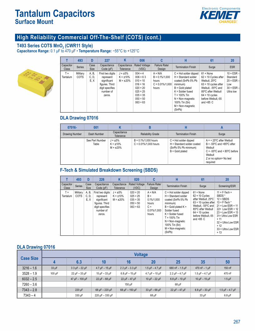
267
Tantalum CapacitorsSurface Mount
High Reliability Commercial Off-The-Shelf (COTS) (cont.) T493 Series COTS MnO2 (CWR11 Style)Capacitance Range: 0.1 μF to 470 μF • Temperature Range: −55°C to +125°C
SPICE
f y e tu e, ipp e, a bi on t ons.
Order ng Information
T 493 D 227 K 006 C H 61 20Capacitor
Class Series Case Size
Capacitance Code (pF)
Capacitance Tolerance
Rated Voltage (VDC)
Failure Rate/Design Termination Finish Surge ESR
T = Tantalum
Military COTS
A, B, C, D, E, X
First two digits represent signifi cant
fi gures. Third digit specifi es
number of zeros.
J = ±5%K = ±10%M = ±20%
004 = 4006 = 6 3010 = 10016 = 16020 = 20025 = 25035 = 35050 = 50063 = 63
A = N/AB = 0.1%/1,000 hours C = 0.01%/1,000 hours
C = Hot solder dipped H = Standard solder coated (SnPb 5% Pb minimum)B = Gold platedK = Solder fusedT = 100% TinN = Non-magnetic 100% Tin (Sn)M = Non-magnetic (SnPb)
61 = None 62 = 10 Cycles after Weibull, 25ºC 63 = 10 cycles after Weibull, -55ºC and 85ºC after Weibull64 = 10 cycles before Weibull,-55 and +85 C
10 = ESR – Standard20 = ESR – Low30 = ESR – Ultra low
DLA Drawing 07016
Orde ng Information
07016- 001 K B H ADrawing Number Dash Number Capacitance
Tolerance Reliability Grade Termination Finish Surge
See Part Number Table
J = ±5%K = ±10%M = ±20%
B = 0.1%/1,000 hours C = 0.01%/1,000 hours
C = Hot solder dipped H = Standard solder coated (SnPb 5% Pb minimum)B = Gold plated
A = + 25ºC after WeibullB = -55ºC and +85ºC after WeibullC = -55ºC and + 85ºC before Weibull Z or no option= No test required
F-Tech & Simulated Breakdown Screening (SBDS)
– High Rel a (COT )
7016- 001
Tab e
±10% ±20%
01%/1,000 hour
tandard solder coa
B Gold plated
nd +8
C 55ºC and + 85ºC be We bul Z or no req ired
Ordering nformat on – F- ech & imulated B eakdow
T 493 D 226 K 020 C H 61 20Capacitor
Class Series Case Size
Capacitance Code (pF)
Capacitance Tolerance
Rated Voltage (VDC)
Failure Rate/ Design Termination Finish Surge Screening/ESR
T = Tantalum
Military COTS
A, B, C, D, E, X
First two digits represent signifi cant
fi gures. Third digit specifi es
number of zeros.
J = ±5% K = ±10% M = ±20%
020 = 20 025 = 25 035 = 35 050 = 50 063 = 63
A = N/AB = 0.1%/1,000 hours C = 0.01%/1,000 hours
C = Hot solder dipped H = Standard solder coated (SnPb 5% Pb minimum) B = Gold plated K = Solder fused K = Solder fused T = 100% Tin N = Non-magnetic 100% Tin (Sn) M = Non-magnetic (SnPb)
61 = None 62 = 10 Cycles after Weibull, 25ºC 63 = 10 cycles after Weibull, -55ºC and 85ºC after Weibull64 = 10 cycles before Weibull,-55 and +85 C
11 = F-Tech + SBDS *12 = SBDS13 = F-Tech *21 = Low ESR + 1122= Low ESR + 1223 = Low ESR + 1331= Ultra Low ESR + 1132 = Ultra Low ESR + 1233 = Ultra Low ESR + 13
DLA Drawing 07016
Case SizeVoltage
4 6.3 10 16 20 25 35 503216 – 1.6 33 μF 3 3 μF – 22 μF 4.7 μF – 15 μF 2 2 μF – 3.3 μF 1.5 μF – 4.7 μF 680 nF – 1.5 μF 470 nF – 1 μF 150 nF
3528 – 1.9 100 μF 22 μF – 33 μF 15 μF – 33 μF 6.8 μF – 15 μF 4.7 μF – 10 μF 2.2 μF – 4.7 μF 1.5 μF – 4.7 μF 470 nF
6032 – 2.5 47 μF – 100 μF 22 μF – 68 μF 22 μF – 47 μF 10 μF – 22 μF 6.8 μF – 10 μF 10 μF – 15 μF 1 5 μF
7260 – 3.6 150 μF 68 μF
7343 – 2.8 220 μF 68 μF – 220 μF 68 μF – 150 μF 33 μF – 68 μF 22 μF – 47 μF 6.8 μF – 33 μF 1.5 μF – 4.7 μF
7343 – 4 330 μF 220 μF – 330 μF 68 μF 33 μF 6.8 μF
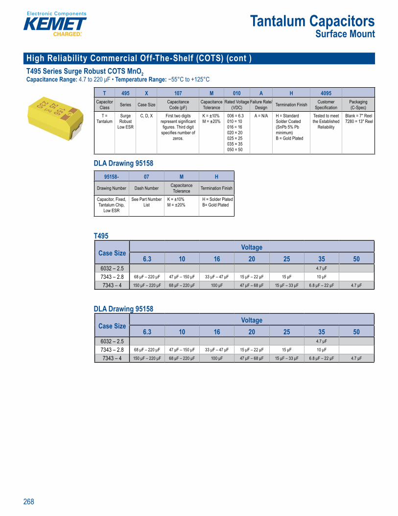
268
Tantalum CapacitorsSurface Mount
High Reliability Commercial Off-The-Shelf (COTS) (cont )T495 Series Surge Robust COTS MnO2Capacitance Range: 4.7 to 220 μF • Temperature Range: −55°C to +125°C
M t ap c to s H liabT495 S r es S e Rob Comm c O f e-S e f COTS) w S M 2 D Dr w ng
Order ng nfo mation
T 495 X 107 M 010 A H 4095Capacitor
Class Series Case Size Capacitance Code (pF)
Capacitance Tolerance
Rated Voltage (VDC)
Failure Rate/Design Termination Finish Customer
Specifi cationPackaging (C-Spec)
T = Tantalum
Surge Robust
Low ESR
C, D, X First two digits represent signifi cant fi gures. Third digit
specifi es number of zeros.
K = ±10% M = ±20%
006 = 6.3010 = 10 016 = 16 020 = 20 025 = 25 035 = 35 050 = 50
A = N/A H = Standard Solder Coated (SnPb 5% Pb minimum) B = Gold Plated
Tested to meet the Established
Reliability
Blank = 7" Reel 7280 = 13" Reel
DLA Drawing 95158
T495 S r es Surge Robu Commerc l Off The-Shelf COTS) Low SR Mn 2 DLA Drawi g
r r g f t n
T 495 107 M 010 A H 4095Capa it r
Class Series Case Size Capa itan e C de (pF)
Capa itan e Toleran e
Rated V ltage (VDC)
Failure Rate/Design Terminati n Finish Customer
Spe ifi cati nPa kaging (C Spe )
T = Tantalum
Surge R bust
L w ESR
C D X First two digits represent signifi cant fi gures Third digit
spe ifi es number f zer s
K = ±10% M = ±20%
006 = 6 3010 = 10 016 = 16 020 = 20 025 = 25 035 = 35 050 = 50
A = N A H = Standard S lder C ated (SnPb 5% Pb minimum) B = G ld Plated
Tested to meet the Established
Reliability
Blank = 7 Reel 7280 = 13 Reel
Orde ing nf rmation
95158- 07 M H
Drawing Number Dash Number Capacitance Tolerance Termination Finish
Capacitor, Fixed, Tantalum Chip,
Low ESR
See Part Number List
K = ±10% M = ±20%
H = Solder Plated B= Gold Plated
T495
Case SizeVoltage
6.3 10 16 20 25 35 506032 – 2.5 4.7 μF
7343 – 2.8 68 μF – 220 μF 47 μF – 150 μF 33 μF – 47 μF 15 μF – 22 μF 15 μF 10 μF
7343 – 4 150 μF – 220 μF 68 μF – 220 μF 100 μF 47 μF – 68 μF 15 μF – 33 μF 6.8 μF – 22 μF 4.7 μF
DLA Drawing 95158
Case SizeVoltage
6.3 10 16 20 25 35 506032 – 2.5 4.7 μF
7343 – 2.8 68 μF – 220 μF 47 μF – 150 μF 33 μF – 47 μF 15 μF – 22 μF 15 μF 10 μF
7343 – 4 150 μF – 220 μF 68 μF – 220 μF 100 μF 47 μF – 68 μF 15 μF – 33 μF 6.8 μF – 22 μF 4.7 μF
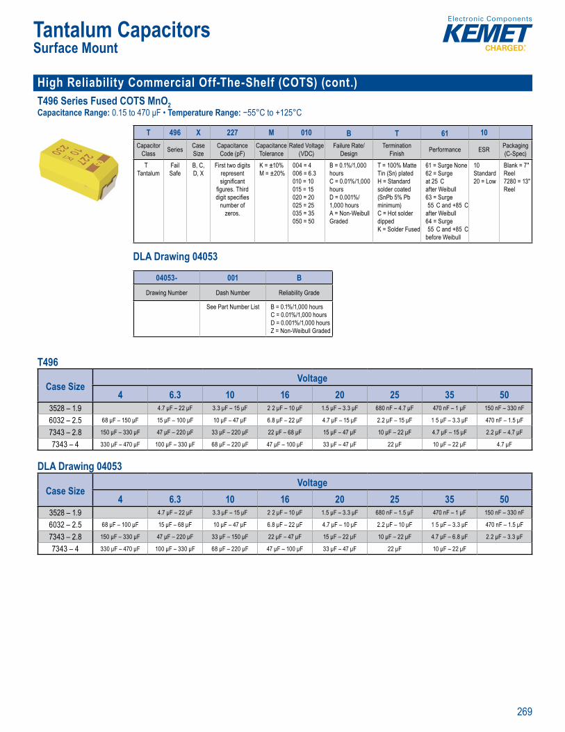
269
Tantalum CapacitorsSurface Mount
High Reliability Commercial Off-The-Shelf (COTS) (cont.) T496 Series Fused COTS MnO2Capacitance Range: 0.15 to 470 μF • Temperature Range: −55°C to +125°C
SPICE
, ,
Orde in Information
T 496 X 227 M 010 B T 61 10Capacitor
Class Series CaseSize
Capacitance Code (pF)
Capacitance Tolerance
Rated Voltage (VDC)
Failure Rate/ Design
Termination Finish Performance ESR Packaging
(C-Spec)
T Tantalum
Fail Safe
B, C, D, X
First two digits represent signifi cant
fi gures. Third digit specifi es
number of zeros.
K = ±10%M = ±20%
004 = 4 006 = 6.3 010 = 10 015 = 15 020 = 20 025 = 25 035 = 35 050 = 50
B = 0.1%/1,000 hours C = 0.01%/1,000 hoursD = 0.001%/1,000 hoursA = Non-Weibull Graded
T = 100% Matte Tin (Sn) platedH = Standard solder coated (SnPb 5% Pb minimum)C = Hot solder dippedK = Solder Fused
61 = Surge None62 = Surge at 25 C after Weibull 63 = Surge 55 C and +85 C
after Weibull64 = Surge 55 C and +85 C
before Weibull
10 Standard20 = Low
Blank = 7" Reel7280 = 13" Reel
DLA Drawing 04053
S ICE
Ordering
C ass Size ac t
Code (pF)cit
Toleranced V
(V C)e
De gnn
Finish (C-Spec)
T = ta
Sa e
B C D, X
st tw d represent signifi cant
gures Thir dig t sp cifi es
number of zeros
= ±10%M ±2 %
4 = 4 006 6 0 0 1 015 = 15 020 20 025 25 035 = 35 050 50
0 1%/1 0 hour C = 0 houD = 01 0 0 hoursA = on We G aded
1 0% M T n Sn platedH = Standard sol er coated (SnPb 5% Pb minimum)C = Hot so d p edK = So
62 Surge at 5 C af er 63 = Surge -5 C and a te Weibull64 = Surge -55 C and be re We bull
Stan20 = Low
Bl nk = 7 Reel7280 Reel
Ordering Information
04053- 001 B
Drawing Number Dash Number Reliability Grade
See Part Number List B = 0.1%/1,000 hours C = 0.01%/1,000 hoursD = 0.001%/1,000 hoursZ = Non-Weibull Graded
T496
Case SizeVoltage
4 6.3 10 16 20 25 35 503528 – 1.9 4.7 μF – 22 μF 3.3 μF – 15 μF 2 2 μF – 10 μF 1.5 μF – 3.3 μF 680 nF – 4.7 μF 470 nF – 1 μF 150 nF – 330 nF
6032 – 2.5 68 μF – 150 μF 15 μF – 100 μF 10 μF – 47 μF 6.8 μF – 22 μF 4.7 μF – 15 μF 2.2 μF – 15 μF 1 5 μF – 3.3 μF 470 nF – 1.5 μF
7343 – 2.8 150 μF – 330 μF 47 μF – 220 μF 33 μF – 220 μF 22 μF – 68 μF 15 μF – 47 μF 10 μF – 22 μF 4.7 μF – 15 μF 2.2 μF – 4.7 μF
7343 – 4 330 μF – 470 μF 100 μF – 330 μF 68 μF – 220 μF 47 μF – 100 μF 33 μF – 47 μF 22 μF 10 μF – 22 μF 4.7 μF
DLA Drawing 04053
Case SizeVoltage
4 6.3 10 16 20 25 35 503528 – 1.9 4.7 μF – 22 μF 3.3 μF – 15 μF 2 2 μF – 10 μF 1.5 μF – 3.3 μF 680 nF – 1.5 μF 470 nF – 1 μF 150 nF – 330 nF
6032 – 2.5 68 μF – 100 μF 15 μF – 68 μF 10 μF – 47 μF 6.8 μF – 22 μF 4.7 μF – 10 μF 2.2 μF – 10 μF 1 5 μF – 3.3 μF 470 nF – 1.5 μF
7343 – 2.8 150 μF – 330 μF 47 μF – 220 μF 33 μF – 150 μF 22 μF – 47 μF 15 μF – 22 μF 10 μF – 22 μF 4.7 μF – 6.8 μF 2.2 μF – 3.3 μF
7343 – 4 330 μF – 470 μF 100 μF – 330 μF 68 μF – 220 μF 47 μF – 100 μF 33 μF – 47 μF 22 μF 10 μF – 22 μF
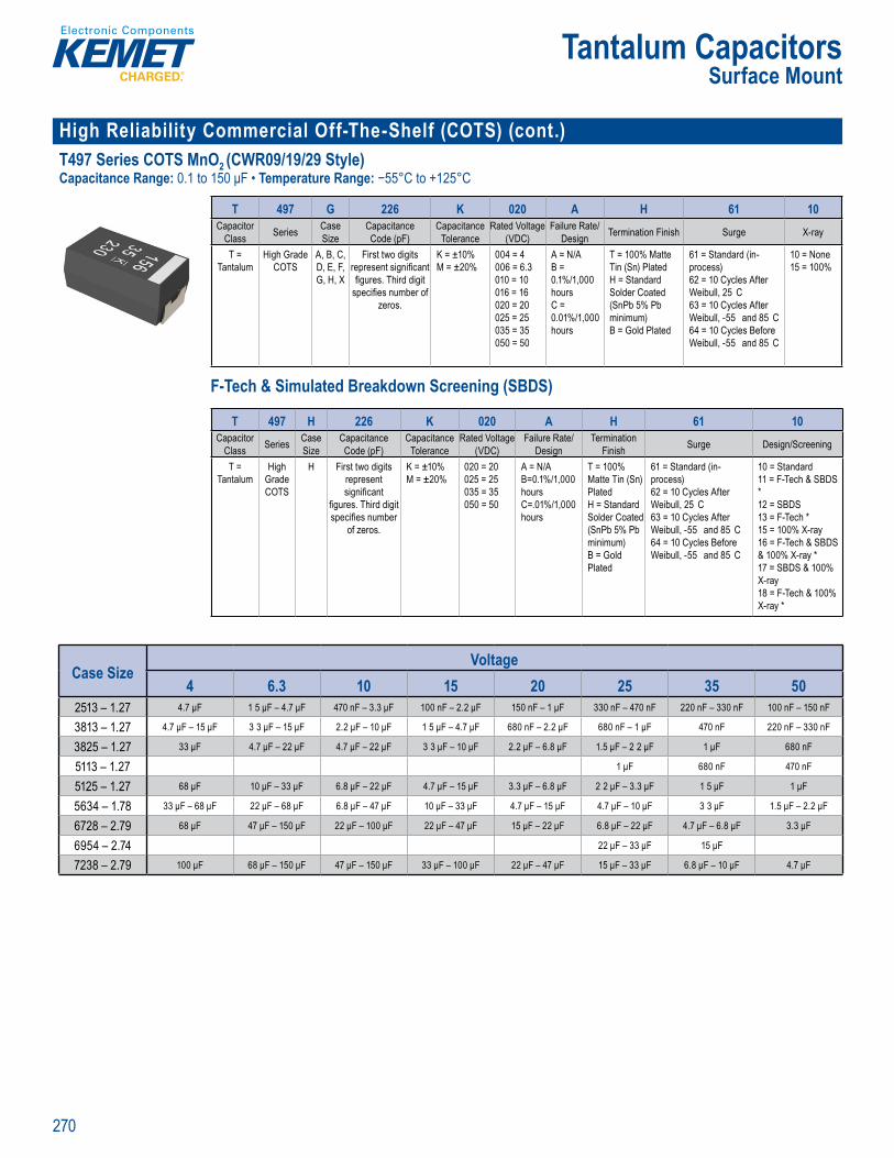
270
Tantalum CapacitorsSurface Mount
High Reliability Commercial Off-The-Shelf (COTS) (cont.)T497 Series COTS MnO2 (CWR09/19/29 Style)Capacitance Range: 0.1 to 150 μF • Temperature Range: −55°C to +125°C
s SP CE softw re
rder g nf mation
T 497 G 226 K 020 A H 61 10Capacitor
Class Series Case Size
Capacitance Code (pF)
Capacitance Tolerance
Rated Voltage (VDC)
Failure Rate/Design Termination Finish Surge X-ray
T = Tantalum
High Grade COTS
A, B, C, D, E, F, G, H, X
First two digits represent signifi cant fi gures. Third digit
specifi es number of zeros.
K = ±10%M = ±20%
004 = 4006 = 6.3010 = 10016 = 16020 = 20025 = 25035 = 35050 = 50
A = N/AB = 0.1%/1,000 hours C = 0.01%/1,000 hours
T = 100% Matte Tin (Sn) PlatedH = Standard Solder Coated (SnPb 5% Pb minimum) B = Gold Plated
61 = Standard (in-process)62 = 10 Cycles After Weibull, 25 C63 = 10 Cycles After Weibull, -55 and 85 C64 = 10 Cycles Before Weibull, -55 and 85 C
10 = None15 = 100%
F-Tech & Simulated Breakdown Screening (SBDS)
)
Ordering nformat on – F-Tech & Simulated B eakdow
T 497 H 226 K 020 A H 61 10Capacitor
Class Series Case Size
Capacitance Code (pF)
Capacitance Tolerance
Rated Voltage (VDC)
Failure Rate/Design
Termination Finish Surge Design/Screening
T = Tantalum
High Grade COTS
H First two digits represent signifi cant
fi gures. Third digit specifi es number
of zeros.
K = ±10% M = ±20%
020 = 20025 = 25035 = 35050 = 50
A = N/AB=0.1%/1,000 hoursC=.01%/1,000 hours
T = 100% Matte Tin (Sn) PlatedH = Standard Solder Coated (SnPb 5% Pb minimum) B = Gold Plated
61 = Standard (in-process)62 = 10 Cycles After Weibull, 25 C63 = 10 Cycles After Weibull, -55 and 85 C64 = 10 Cycles Before Weibull, -55 and 85 C
10 = Standard11 = F-Tech & SBDS *12 = SBDS13 = F-Tech *15 = 100% X-ray16 = F-Tech & SBDS & 100% X-ray *17 = SBDS & 100% X-ray18 = F-Tech & 100% X-ray *
Case SizeVoltage
4 6.3 10 15 20 25 35 502513 – 1.27 4.7 μF 1 5 μF – 4.7 μF 470 nF – 3.3 μF 100 nF – 2.2 μF 150 nF – 1 μF 330 nF – 470 nF 220 nF – 330 nF 100 nF – 150 nF
3813 – 1.27 4.7 μF – 15 μF 3 3 μF – 15 μF 2.2 μF – 10 μF 1 5 μF – 4.7 μF 680 nF – 2.2 μF 680 nF – 1 μF 470 nF 220 nF – 330 nF
3825 – 1.27 33 μF 4.7 μF – 22 μF 4.7 μF – 22 μF 3 3 μF – 10 μF 2.2 μF – 6.8 μF 1.5 μF – 2 2 μF 1 μF 680 nF
5113 – 1.27 1 μF 680 nF 470 nF
5125 – 1.27 68 μF 10 μF – 33 μF 6.8 μF – 22 μF 4.7 μF – 15 μF 3.3 μF – 6.8 μF 2 2 μF – 3.3 μF 1 5 μF 1 μF
5634 – 1.78 33 μF – 68 μF 22 μF – 68 μF 6.8 μF – 47 μF 10 μF – 33 μF 4.7 μF – 15 μF 4.7 μF – 10 μF 3 3 μF 1.5 μF – 2.2 μF
6728 – 2.79 68 μF 47 μF – 150 μF 22 μF – 100 μF 22 μF – 47 μF 15 μF – 22 μF 6.8 μF – 22 μF 4.7 μF – 6.8 μF 3.3 μF
6954 – 2.74 22 μF – 33 μF 15 μF
7238 – 2.79 100 μF 68 μF – 150 μF 47 μF – 150 μF 33 μF – 100 μF 22 μF – 47 μF 15 μF – 33 μF 6.8 μF – 10 μF 4.7 μF
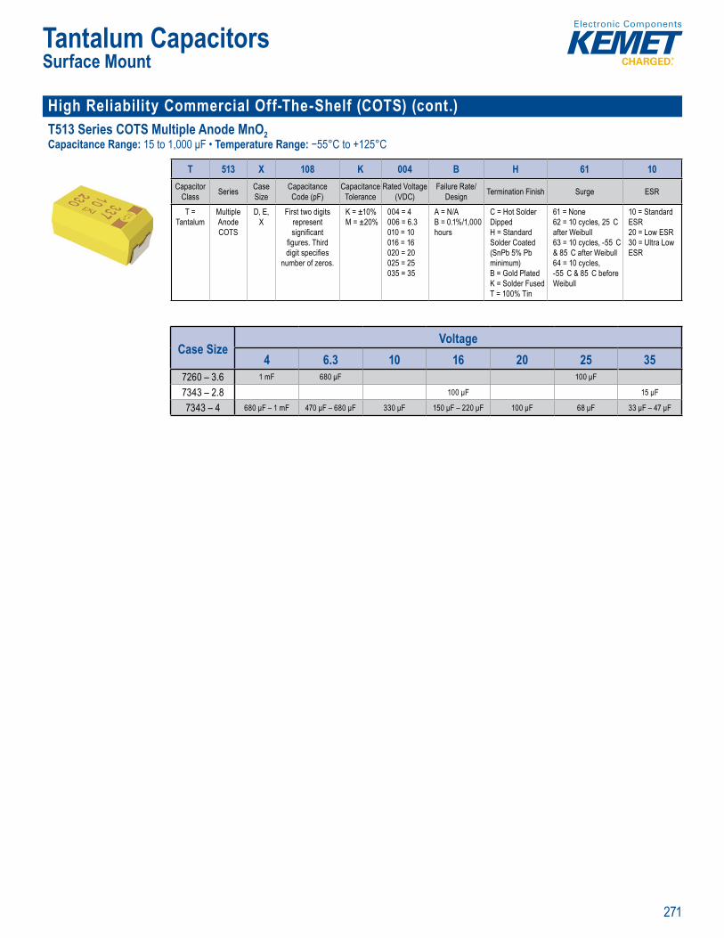
271
Tantalum CapacitorsSurface Mount
High Reliability Commercial Off-The-Shelf (COTS) (cont.)T513 Series COTS Multiple Anode MnO2Capacitance Range: 15 to 1,000 μF • Temperature Range: −55°C to +125°C
SPICE
Orderin Informa ion
T 513 X 108 K 004 B H 61 10Capacitor
Class Series Case Size
Capacitance Code (pF)
Capacitance Tolerance
Rated Voltage (VDC)
Failure Rate/Design Termination Finish Surge ESR
T = Tantalum
Multiple Anode COTS
D, E, X
First two digits represent signifi cant
fi gures. Third digit specifi es
number of zeros.
K = ±10%M = ±20%
004 = 4 006 = 6.3 010 = 10 016 = 16 020 = 20 025 = 25 035 = 35
A = N/AB = 0.1%/1,000 hours
C = Hot Solder Dipped H = Standard Solder Coated (SnPb 5% Pb minimum) B = Gold Plated K = Solder Fused T = 100% Tin
61 = None62 = 10 cycles, 25 C after Weibull63 = 10 cycles, -55 C & 85 C after Weibull64 = 10 cycles, -55 C & 85 C before Weibull
10 = Standard ESR20 = Low ESR 30 = Ultra Low ESR
Case SizeVoltage
4 6.3 10 16 20 25 357260 – 3.6 1 mF 680 μF 100 μF
7343 – 2.8 100 μF 15 μF
7343 – 4 680 μF – 1 mF 470 μF – 680 μF 330 μF 150 μF – 220 μF 100 μF 68 μF 33 μF – 47 μF
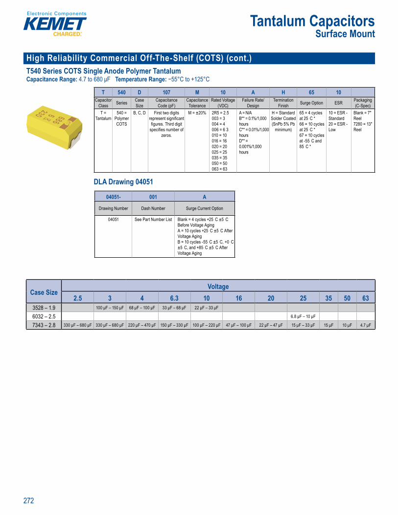
272
Tantalum CapacitorsSurface Mount
High Reliability Commercial Off-The-Shelf (COTS) (cont.)T540 Series COTS Single Anode Polymer TantalumCapacitance Range: 4.7 to 680 μF Temperature Range: −55°C to +125°C
's SP CE softw re
Order ng fo mation
T 540 D 107 M 10 A H 65 10Capacitor
Class Series Case Size
Capacitance Code (pF)
Capacitance Tolerance
Rated Voltage (VDC)
Failure Rate/Design
Termination Finish Surge Option ESR Packaging
(C-Spec)T =
Tantalum540 =
Polymer COTS
B, C, D First two digits represent signifi cant fi gures. Third digit
specifi es number of zeros.
M = ±20% 2R5 = 2.5003 = 3004 = 4006 = 6 3010 = 10016 = 16020 = 20025 = 25035 = 35050 = 50063 = 63
A = N/AB** = 0.1%/1,000 hours C** = 0.01%/1,000 hoursD** = 0.001%/1,000 hours
H = Standard Solder Coated (SnPb 5% Pb
minimum)
65 = 4 cycles at 25 C *66 = 10 cycles at 25 C *67 = 10 cycles at -55 C and 85 C *
10 = ESR - Standard20 = ESR - Low
Blank = 7" Reel 7280 = 13" Reel
DLA Drawing 04051
m or a f ee down oa f K M T s SPICE softwar . the e a ov
O d ri nf r t
540 D M
la iz
de (p
era
D
es
ni
T a
Polyme
B, C, irst two di i e n n
d ecifi es number
ze os
M ±2 % 2R5 .5
006 = 6 3010 = 16 1
020 = 20025 = 25
35 3050 = 506 = 6
= N
C** = 0 h ur
** = 0 0 %/ 00 hou s
Stand r de
minimum)
at 25 C *
at 2 C *6 10 t and
85 C *
nda
Bl nk 7 eel
3 Reel
Ordering Information
04051- 001 A
Drawing Number Dash Number Surge Current Option
04051 See Part Number List Blank = 4 cycles +25 C ±5 C Before Voltage AgingA = 10 cycles +25 C ±5 C After Voltage AgingB = 10 cycles -55 C ±5 C, +0 C ±5 C, and +85 C ±5 C After Voltage Aging
Case SizeVoltage
2.5 3 4 6.3 10 16 20 25 35 50 633528 – 1.9 100 μF – 150 μF 68 μF – 100 μF 33 μF – 68 μF 22 μF – 33 μF
6032 – 2.5 6.8 μF – 10 μF
7343 – 2.8 330 μF – 680 μF 330 μF – 680 μF 220 μF – 470 μF 150 μF – 330 μF 100 μF – 220 μF 47 μF – 100 μF 22 μF – 47 μF 15 μF – 33 μF 15 μF 10 μF 4.7 μF
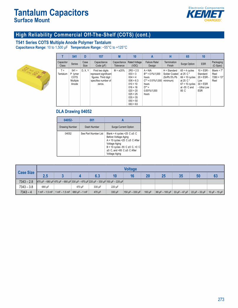
273
Tantalum CapacitorsSurface Mount
High Reliability Commercial Off-The-Shelf (COTS) (cont.)T541 Series COTS Multiple Anode Polymer TantalumCapacitance Range: 10 to 1,500 μF Temperature Range: −55°C to +125°C
SPICE
, p ,
Orderin Information
T 541 D 157 M 10 A H 65 10Capacitor
Class Series Case Size
Capacitance Code (pF)
Capacitance Tolerance
Rated Voltage (VDC)
Failure Rate/Design
Termination Finish Surge Option ESR Packaging
(C-Spec)
T = Tantalum
541 = P lymer COTS
Multiple Anode
D, X, Y First two digits represent signifi cant fi gures. Third digit
specifi es number of zeros.
M = ±20% 2R5 = 2.5003 = 3004 = 4006 = 6.3010 = 10016 = 16020 = 20025 = 25035 = 35050 = 50063 = 63
A = N/AB** = 0.1%/1,000 hours C** = 0 01%/1,000 hoursD** = 0.001%/1,000 hours
H = Standard Solder Coated (SnPb 5% Pb minimum)
65 = 4 cycles at 25 C *66 = 10 cycles at 25 C *67 = 10 cycles at -55 C and 85 C
10 = ESR - Standard20 = ESR - Low30 = ESR - Ultra Low ESR
Blank = 7" Reel 7280 = 13" Reel
DLA Drawing 04052
For a detai ed analysi of e
O f
54 D 57 M
l Si
de
era
VD
es
n
T = antalu
Polyme
Mult p Anode
D, X, irst wo d i e nt signi
d pecifi es numbe
zeros
M ±2 2R = 2.53 = 3
0 6 6 310 16 12 02 23 3
0 506 6
A N = .1 /
C** = 0 h u sD** = 0 01% 1 000 hours
Standar der C
mi imum)
at 25 C *
2 C *
67 10 t - 5 C and
85
anda
L w30 = ESR - U ra Lo ESR
B ank = 7 R el 7 Reel
O d ring Info mation
04052- 001 A
Drawing Number Dash Number Surge Current Option
04052 See Part Number List Blank = 4 cycles +25 C ±5 C Before Voltage AgingA = 10 cycles +25 C ±5 C After Voltage AgingB = 10 cycles -55 C ±5 C, +0 C ±5 C, and +85 C ±5 C After Voltage Aging
Case SizeVoltage
2.5 3 4 6.3 10 16 20 25 35 50 637343 – 2.8 470 μF – 680 μF 470 μF – 680 μF 330 μF – 470 μF 220 μF – 330 μF 150 μF – 220 μF
7343 – 3.8 680 μF 470 μF 330 μF 220 μF
7343 – 4 1 mF – 1.5 mF 1 mF – 1.5 mF 680 μF – 1 mF 470 μF 330 μF 150 μF – 330 μF 100 μF 68 μF – 100 μF 33 μF – 47 μF 22 μF – 33 μF 10 μF – 15 μF

274
Tantalum CapacitorsSurface Mount
High Reliability Commercial Off-The-Shelf (COTS) (cont.)T543 Series COTS Polymer TantalumCapacitance Range: 4.7 to 1,500 μF • Temperature Range: −55°C to +105°C
s SP CE softw re
rderin Informat o
T 543 D 156 K 035 A H E 100Capacitor
Class Series Case Size
Capacitance Code(pF)
Capacitance Tolerance
Rated Voltage (VDC)
Failure Rate/ Design
TerminationFinish Surge ESR Packaging
(C-Spec)
T = Tantalum
Polymer Tantalum
COTS
A, B, C, D, H, L, M, T, U, V, W, X, Y
First two digits represent signifi cant fi gures. Third digit
specifi es number of zeros.
K = ±10%M = ±20%
2R5 = 2.5003 = 3004 = 4006 = 6 3010 = 1012R = 12.5016 = 16020 = 20025 = 25035 = 35050 = 50063 =63
A = N/A H = Standard Solder Coated (SnPb 5% Pb minimum)T = 100% Tin (Sn)
E = NoneS = 10 cycles 25 CW = 10 cycles -55 C and 85 C
ESR in mΩ
Blank = 7" Reel7280 = 13" Reel
Case SizeVoltage
2.5 3 4 6.3 8 10 12.5 163216 – 1.6 47 μF – 68 μF 33 μF – 100 μF 22 μF – 68 μF 10 μF – 22 μF
3528 – 1.2 56 μF – 100 μF 15 μF – 100 μF 15 μF – 100 μF 33 μF 33 μF 10 μF – 15 μF
3528 – 1.5 150 μF
3528 – 1.9 100 μF – 330 μF 100 μF – 150 μF 68 μF – 220 μF 33 μF – 220 μF 33 μF – 47 μF 22 μF – 47 μF 10 μF
6032 – 1.5 150 μF – 220 μF 68 μF – 150 μF 68 μF – 150 μF 33 μF 33 μF – 68 μF
6032 – 1.9 330 μF 220 μF 150 μF 100 μF
6032 – 2.5 220 μF – 470 μF 150 μF – 330 μF 33 μF – 220 μF 47 μF – 150 μF 22 μF
7343 – 1.5 220 μF – 330 μF 220 μF 100 μF – 470 μF 68 μF – 100 μF 33 μF – 47 μF
7343 – 1.9 220 μF – 470 μF 330 μF 150 μF – 330 μF 100 μF – 470 μF 150 μF 68 μF – 220 μF 33 μF – 100 μF
7343 – 2.8 220 μF – 680 μF 330 μF – 680 μF 220 μF – 680 μF 150 μF – 470 μF 150 μF 68 μF – 220 μF 47 μF – 100 μF
7343 – 3.8 680 μF – 1 mF 470 μF – 680 μF 330 μF – 470 μF 150 μF – 330 μF
7343 – 4 680 μF – 1.5 mF 1 mF – 1.5 mF 680 μF – 1 mF 470 μF – 680 μF 330 μF 330 μF 150 μF – 330 μF
7360 – 2 1 mF – 1.5 mF
Case SizeVoltage
20 25 35 50 637343 – 1.9 22 μF – 47 μF 15 μF – 33 μF 15 μF
7343 – 2.8 22 μF – 47 μF 15 μF – 33 μF 15 μF 5.6 μF – 10 μF 4.7 μF
7343 – 3.8
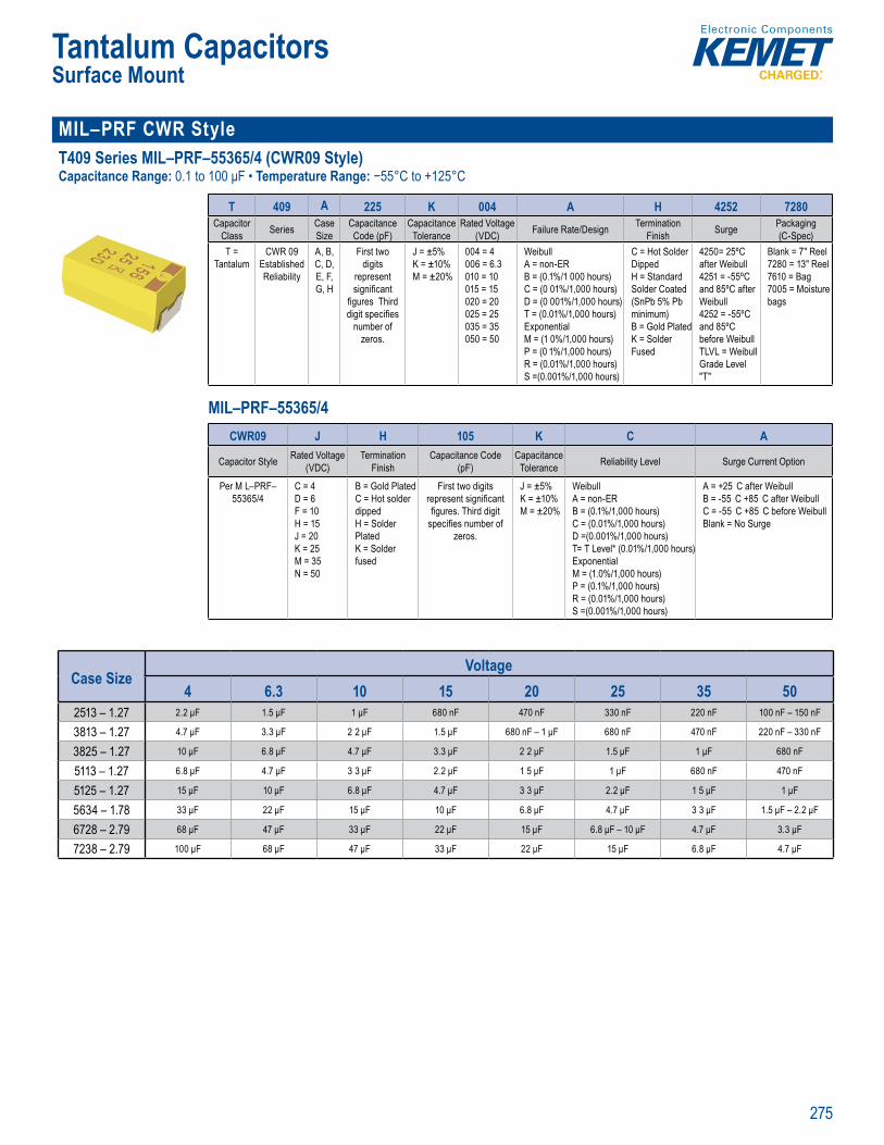
275
Tantalum CapacitorsSurface Mount
MIL–PRF CWR Style T409 Series MIL–PRF–55365/4 (CWR09 Style)Capacitance Range: 0.1 to 100 μF • Temperature Range: −55°C to +125°C
n T4
KE E Ordering I fo mat n
T 409 A 225 K 004 A H 4252 7280Capacitor
Class Series Case Size
Capacitance Code (pF)
Capacitance Tolerance
Rated Voltage (VDC) Failure Rate/Design Termination
Finish Surge Packaging (C-Spec)
T = Tantalum
CWR 09 Established Reliability
A, B, C, D, E, F, G, H
First two digits
represent signifi cant
fi gures Third digit specifi es
number of zeros.
J = ±5%K = ±10%M = ±20%
004 = 4 006 = 6.3010 = 10015 = 15020 = 20025 = 25035 = 35050 = 50
Weibull A = non-ERB = (0.1%/1 000 hours)C = (0 01%/1,000 hours)D = (0 001%/1,000 hours)T = (0.01%/1,000 hours) ExponentialM = (1 0%/1,000 hours)P = (0 1%/1,000 hours)R = (0.01%/1,000 hours)S =(0.001%/1,000 hours)
C = Hot Solder Dipped H = Standard Solder Coated (SnPb 5% Pb minimum) B = Gold Plated K = Solder Fused
4250= 25ºC after Weibull 4251 = -55ºC and 85ºC after Weibull 4252 = -55ºC and 85ºC before WeibullTLVL = Weibull Grade Level "T"
Blank = 7" Reel7280 = 13" Reel7610 = Bag7005 = Moisture bags
MIL–PRF–55365/4
ME Ordering Inf ma
Tac er e a
acit
cit d Vo at in Surge ckagi
T l
CWR 09
e iab l t
, B C D E F G H
Fi t t di t
r present nifi ca
gures Thir g t specifi e number of
eros
J 5% 1
M ± 0
6 3
010 = 10015 = 10 0 = 00 5 = 5035 = 35050 = 50
e bull
B = (0 1 C = (0 01% D = (0 01% 1 000 houT = (0 0 %/1,000 urs) Ex onent al
= ( 0%/1 0 0 hours)P = 0 1%/1 R = (0 01%/1 00 hoursS =(0 001%/ 0 0 hour
S d d
H = Standard Solder (SnPb 5% Pb minimum) B = G ld Pl t K = So de F d
0= 25
4251 = -5 C and ºC aft We bu 425 55ºC and 85º befo e We uTLV = Grade Leve T"
7" R
7610 g7005 = M sture bag
Ord ring fo matio
CWR09 J H 105 K C A
Capacitor Style Rated Voltage (VDC)
Termination Finish
Capacitance Code (pF)
Capacitance Tolerance Reliability Level Surge Current Option
Per M L–PRF–55365/4
C = 4D = 6F = 10H = 15J = 20K = 25M = 35N = 50
B = Gold PlatedC = Hot solder dippedH = Solder PlatedK = Solder fused
First two digits represent signifi cant fi gures. Third digit
specifi es number of zeros.
J = ±5%K = ±10%M = ±20%
Weibull A = non-ERB = (0.1%/1,000 hours)C = (0.01%/1,000 hours)D =(0.001%/1,000 hours)T= T Level* (0.01%/1,000 hours) ExponentialM = (1.0%/1,000 hours)P = (0.1%/1,000 hours)R = (0.01%/1,000 hours)S =(0.001%/1,000 hours)
A = +25 C after WeibullB = -55 C +85 C after WeibullC = -55 C +85 C before WeibullBlank = No Surge
Case SizeVoltage
4 6.3 10 15 20 25 35 502513 – 1.27 2.2 μF 1.5 μF 1 μF 680 nF 470 nF 330 nF 220 nF 100 nF – 150 nF
3813 – 1.27 4.7 μF 3.3 μF 2 2 μF 1.5 μF 680 nF – 1 μF 680 nF 470 nF 220 nF – 330 nF
3825 – 1.27 10 μF 6.8 μF 4.7 μF 3.3 μF 2 2 μF 1.5 μF 1 μF 680 nF
5113 – 1.27 6.8 μF 4.7 μF 3 3 μF 2.2 μF 1 5 μF 1 μF 680 nF 470 nF
5125 – 1.27 15 μF 10 μF 6.8 μF 4.7 μF 3 3 μF 2.2 μF 1 5 μF 1 μF
5634 – 1.78 33 μF 22 μF 15 μF 10 μF 6.8 μF 4.7 μF 3 3 μF 1.5 μF – 2.2 μF
6728 – 2.79 68 μF 47 μF 33 μF 22 μF 15 μF 6.8 μF – 10 μF 4.7 μF 3.3 μF
7238 – 2.79 100 μF 68 μF 47 μF 33 μF 22 μF 15 μF 6.8 μF 4.7 μF
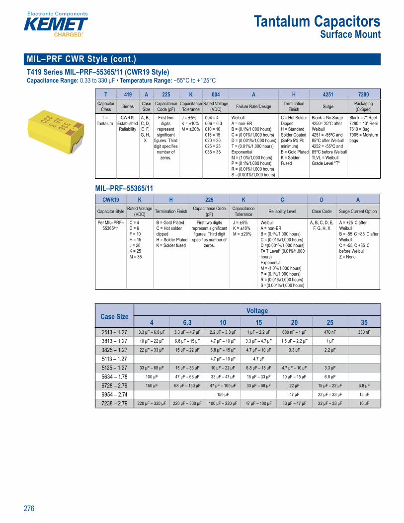
276
Tantalum CapacitorsSurface Mount
MIL–PRF CWR Style (cont.) T419 Series MIL–PRF–55365/11 (CWR19 Style)Capacitance Range: 0.33 to 330 μF • Temperature Range: −55°C to +125°C
n M u T41 S ie P F–
E ET Orderi g nformat n
T 419 A 225 K 004 A H 4251 7280Capacitor
Class Series Case Size
Capacitance Code (pF)
Capacitance Tolerance
Rated Voltage (VDC) Failure Rate/Design Termination
Finish Surge Packaging (C-Spec)
T = Tantalum
CWR19 Established Reliability
A, B, C, D, E F, G, H,
X
First two digits
represent signifi cant
fi gures. Third digit specifi es
number of zeros.
J = ±5% K = ±10%M = ±20%
004 = 4006 = 6 3010 = 10015 = 15020 = 20025 = 25035 = 35
WeibullA = non-ERB = (0.1%/1 000 hours)C = (0 01%/1,000 hours)D = (0 001%/1,000 hours)T = (0.01%/1,000 hours) ExponentialM = (1 0%/1,000 hours)P = (0 1%/1,000 hours)R = (0.01%/1,000 hours)S =(0.001%/1,000 hours)
C = Hot Solder Dipped H = Standard Solder Coated (SnPb 5% Pb minimum) B = Gold Plated K = Solder Fused
Blank = No Surge4250= 25ºC after Weibull4251 = -55ºC and 85ºC after Weibull 4252 = -55ºC and 85ºC before WeibullTLVL = Weibull Grade Level "T"
Blank = 7" Reel7280 = 13" Reel7610 = Bag7005 = Moisture bags
MIL–PRF–55365/11
ME O dering Infor
2a e ie a
acita
cit d Vo t in Sur e ckagi
T W 19
el ab lit
, B,
E F, H X
First two
epresent nifi ca
gures T ir g t specifi e numb r of
eros
J = ±5%
M ± 0
4 = 4
010 = 105
0 0 = 00 5 = 5
35 35
eibull
B = (0 1 C (0 01% D = (0 001% 1 000 houT = (0 01%/1,000 urs) E e l
= ( 0%/1 0 0 hours)P = (0 1%/1 R (0 0 %/1 oursS = 0 0 1%/1 0 0 hour
Hot So
H = Standard Solde (SnPb 5% Pb minim m) B = G l P t K = Solde Fu ed
= No
Weibul4251 5 ºC n 85ºC a 4252 = 55 C and
5 befo WeibuTLVL = W bull G de Leve T"
nk 7
7610 ag70 5 M sture bag
Ord ring fo mat
CWR19 K H 225 K C D A
Capacitor Style Rated Voltage (VDC) Termination Finish Capacitance Code
(pF)Capacitance
Tolerance Reliability Level Case Code Surge Current Option
Per MIL–PRF–55365/11
C = 4D = 6F = 10H = 15J = 20K = 25M = 35
B = Gold PlatedC = Hot solder dippedH = Solder PlatedK = Solder fused
First two digits represent signifi cant fi gures. Third digit
specifi es number of zeros.
J = ±5%K = ±10%M = ±20%
WeibullA = non-ERB = (0.1%/1,000 hours)C = (0.01%/1,000 hours)D =(0.001%/1,000 hours)T= T Level* (0.01%/1,000 hours) ExponentialM = (1.0%/1,000 hours)P = (0.1%/1,000 hours)R = (0.01%/1,000 hours)S =(0.001%/1,000 hours)
A, B, C, D, E, F, G, H, X
A = +25 C after WeibullB = -55 C +85 C after WeibullC = -55 C +85 C before WeibullZ = None
Case SizeVoltage
4 6.3 10 15 20 25 352513 – 1.27 3.3 μF – 6.8 μF 3.3 μF – 4.7 μF 2.2 μF – 3.3 μF 1 μF – 2.2 μF 680 nF – 1 μF 470 nF 330 nF
3813 – 1.27 10 μF – 22 μF 6.8 μF – 15 μF 4.7 μF – 10 μF 3.3 μF – 4.7 μF 1 5 μF – 2.2 μF 1 μF
3825 – 1.27 22 μF – 33 μF 15 μF – 22 μF 6.8 μF – 15 μF 4.7 μF – 10 μF 3.3 μF 2.2 μF
5113 – 1.27 4.7 μF – 10 μF 4.7 μF
5125 – 1.27 33 μF – 68 μF 15 μF – 33 μF 10 μF – 22 μF 6.8 μF – 15 μF 4.7 μF – 10 μF 3.3 μF
5634 – 1.78 100 μF 47 μF – 68 μF 33 μF – 47 μF 15 μF – 33 μF 10 μF – 15 μF 6.8 μF
6728 – 2.79 150 μF 68 μF – 150 μF 47 μF – 100 μF 33 μF – 68 μF 22 μF 15 μF – 22 μF 6.8 μF
6954 – 2.74 150 μF 47 μF 22 μF – 33 μF 15 μF
7238 – 2.79 220 μF – 330 μF 220 μF – 330 μF 100 μF – 220 μF 47 μF – 100 μF 33 μF – 47 μF 22 μF – 33 μF 10 μF
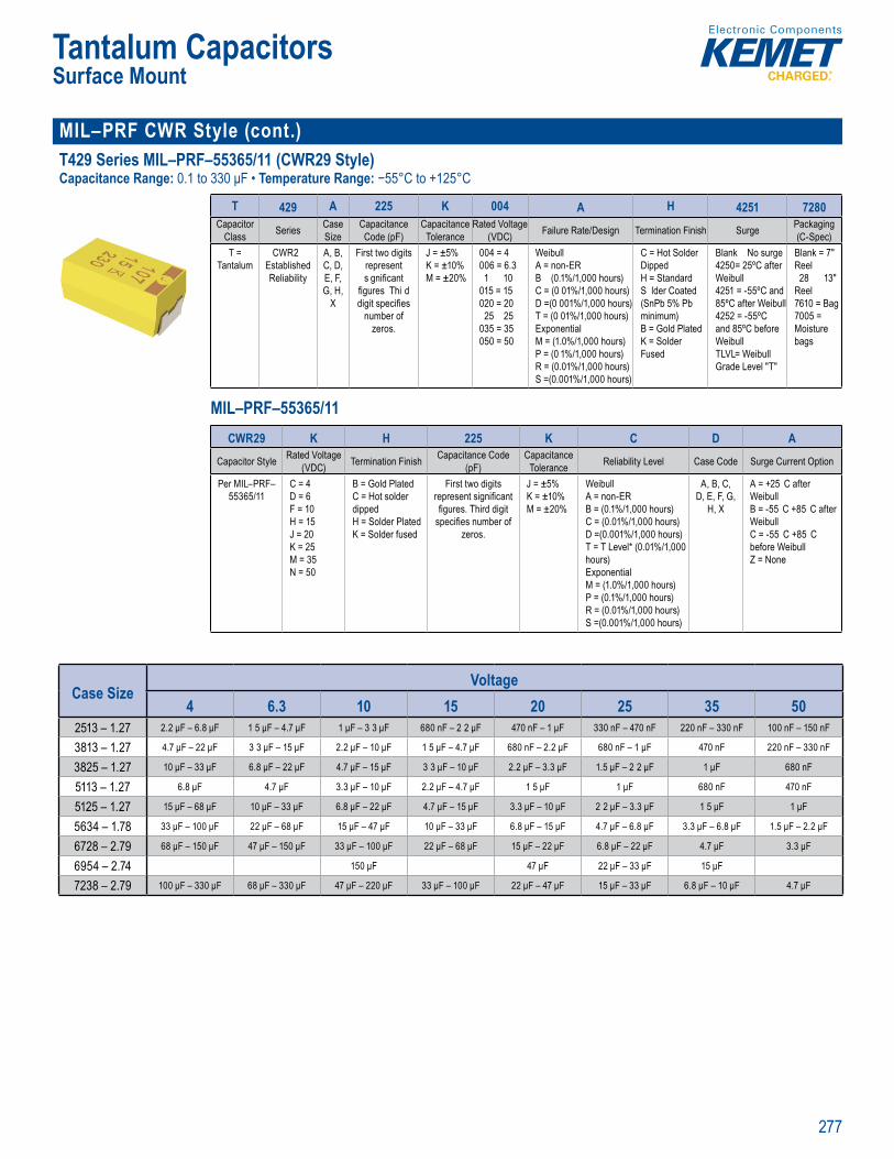
277
Tantalum CapacitorsSurface Mount
MIL–PRF CWR Style (cont.)T429 Series MIL–PRF–55365/11 (CWR29 Style)Capacitance Range: 0.1 to 330 μF • Temperature Range: −55°C to +125°C
n M u T4 S ries MI PRF–
E E O d i g fo ma n
T 429 A 225 K 004 A H 4251 7280Capacitor
Class Series Case Size
Capacitance Code (pF)
Capacitance Tolerance
Rated Voltage (VDC) Failure Rate/Design Termination Finish Surge Packaging
(C-Spec)T =
TantalumCWR2
Established Reliability
A, B, C, D, E, F, G, H,
X
First two digits represent s gnifi cant
fi gures Thi d digit specifi es
number of zeros.
J = ±5% K = ±10%M = ±20%
004 = 4006 = 6.31 10
015 = 15020 = 20
25 25035 = 35050 = 50
WeibullA = non-ERB (0.1%/1,000 hours)C = (0 01%/1,000 hours)D =(0 001%/1,000 hours)T = (0 01%/1,000 hours) ExponentialM = (1.0%/1,000 hours)P = (0 1%/1,000 hours)R = (0.01%/1,000 hours)S =(0.001%/1,000 hours)
C = Hot Solder Dipped H = Standard S lder Coated (SnPb 5% Pb minimum) B = Gold Plated K = Solder Fused
Blank No surge4250= 25ºC after Weibull4251 = -55ºC and 85ºC after Weibull4252 = -55ºC and 85ºC before Weibull TLVL= Weibull Grade Level "T"
Blank = 7" Reel28 13"
Reel7610 = Bag7005 = Moisture bags
MIL–PRF–55365/11
T 429 25 Ka Serie
ac t d (
c t d C a io Surge g
C SpeT = t l
CWR29
el abilit
, B C E F, G, H,
X
irst two digit t
signifi cant gures Thi git specifi e number of
zeros
J = 5% 1
M 0
004 6 6
010 10015 1020 = 200 5 5035 35050 = 50
eibull
B = (0 1 C (0 01%/ D = 0 01%/1 0 0 hourT (0 01%/1,000 ours) E ponential
( .0%/1, 0 hours)P = (0 1%/1 R ( 01%/1 00 hoursS 0 001%/1 0 hour
C = Hot Solder
H Standard Solder (SnPb 5% Pb minim m) B = Gold Plat K = Solde Fu ed
= No
Weib ll4251 55 C and 85ºC a 425 55ºC and 85ºC before We bu TLV Weibull Grade
Bl nk = 7" l
7280 3 Reel7610 = Ba7005 M is u e bags
Ord ring fo mation
CWR29 K H 225 K C D ACapacitor Style Rated Voltage
(VDC) Termination Finish Capacitance Code (pF)
Capacitance Tolerance Reliability Level Case Code Surge Current Option
Per MIL–PRF–55365/11
C = 4D = 6F = 10H = 15J = 20K = 25M = 35N = 50
B = Gold PlatedC = Hot solder dippedH = Solder PlatedK = Solder fused
First two digits represent signifi cant fi gures. Third digit
specifi es number of zeros.
J = ±5%K = ±10%M = ±20%
WeibullA = non-ERB = (0.1%/1,000 hours)C = (0.01%/1,000 hours)D =(0.001%/1,000 hours)T = T Level* (0.01%/1,000 hours) ExponentialM = (1.0%/1,000 hours)P = (0.1%/1,000 hours)R = (0.01%/1,000 hours)S =(0.001%/1,000 hours)
A, B, C, D, E, F, G,
H, X
A = +25 C after WeibullB = -55 C +85 C after WeibullC = -55 C +85 C before WeibullZ = None
Case SizeVoltage
4 6.3 10 15 20 25 35 502513 – 1.27 2.2 μF – 6.8 μF 1 5 μF – 4.7 μF 1 μF – 3 3 μF 680 nF – 2 2 μF 470 nF – 1 μF 330 nF – 470 nF 220 nF – 330 nF 100 nF – 150 nF
3813 – 1.27 4.7 μF – 22 μF 3 3 μF – 15 μF 2.2 μF – 10 μF 1 5 μF – 4.7 μF 680 nF – 2.2 μF 680 nF – 1 μF 470 nF 220 nF – 330 nF
3825 – 1.27 10 μF – 33 μF 6.8 μF – 22 μF 4.7 μF – 15 μF 3 3 μF – 10 μF 2.2 μF – 3.3 μF 1.5 μF – 2 2 μF 1 μF 680 nF
5113 – 1.27 6.8 μF 4.7 μF 3.3 μF – 10 μF 2.2 μF – 4.7 μF 1 5 μF 1 μF 680 nF 470 nF
5125 – 1.27 15 μF – 68 μF 10 μF – 33 μF 6.8 μF – 22 μF 4.7 μF – 15 μF 3.3 μF – 10 μF 2 2 μF – 3.3 μF 1 5 μF 1 μF
5634 – 1.78 33 μF – 100 μF 22 μF – 68 μF 15 μF – 47 μF 10 μF – 33 μF 6.8 μF – 15 μF 4.7 μF – 6.8 μF 3.3 μF – 6.8 μF 1.5 μF – 2.2 μF
6728 – 2.79 68 μF – 150 μF 47 μF – 150 μF 33 μF – 100 μF 22 μF – 68 μF 15 μF – 22 μF 6.8 μF – 22 μF 4.7 μF 3.3 μF
6954 – 2.74 150 μF 47 μF 22 μF – 33 μF 15 μF
7238 – 2.79 100 μF – 330 μF 68 μF – 330 μF 47 μF – 220 μF 33 μF – 100 μF 22 μF – 47 μF 15 μF – 33 μF 6.8 μF – 10 μF 4.7 μF
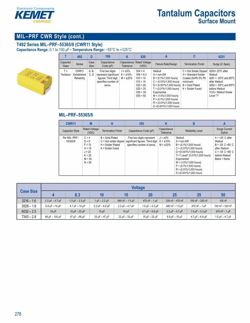
278
Tantalum CapacitorsSurface Mount
MIL–PRF CWR Style (cont.)T492 Series MIL–PRF–55365/8 (CWR11 Style)Capacitance Range: 0.1 to 100 μF • Temperature Range: −55°C to +125°C
T4 S ries MIL–PRF–
KEMET Ord ri fo m
T 492 D 156 K 020 A C 4251Capacitor
Class Series Case Size
Capacitance Code (pF)
Capacitance Tolerance
Rated Voltage (VDC) Failure Rate/Design Termination Finish Surge (C-Spec)
T = Tantalum
CWR11 Established Reliability
A, B, C, D
First two digits represent signifi cant fi gures. Third digit
specifi es number of zeros.
J = ±5%K = ±10%M = ±20%
004 = 4006 = 6.3010 = 10015 = 15020 = 20025 = 25035 = 35050 = 50
WeibullA = non-ERB = (0.1%/1,000 hours)C = (0 01%/1,000 hours)D = (0.001%/1,000 hours)T = (0.01%/1,000 hours) ExponentialM = (1.0%/1,000 hours)P = (0.1%/1,000 hours)R = (0.01%/1,000 hours)S =(0.001%/1,000 hours
C = Hot Solder Dipped H = Standard Solder Coated (SnPb 5% Pb minimum) B = Gold Plated K = Solder Fused
4250= 25ºC after Weibull 4251 = -55ºC and 85ºC after Weibull4252 = -55ºC and 85ºC before WeibullTLVL= Weibull Grade Level "T"
MIL–PRF–55365/8
T 92 D 1 6a
s as
ac ta (p )
ci a
d Vo ) (C
= CW 1
i b l y
A, B
st two digi
T d dig fi u b f
= ±5%
M 2
4 = 4 1
5 253 35 5
bull
B ( 1 C ( 1% D ( , uT ( 01 /1,0 ours) E o
( 0 )P = 0 1%/1,
(0 /1 (0 1 ,
= Hot Sold r Dipp
C ted (S Pb 5% P )
B G ld P K = Solde
0= 25ºC t r
425 5 º W
25 5 C d C bef e WeibuTLVL L "T"
Ord ring fo matio
CWR11 M H 105 K B A
Capacitor Style Rated Voltage (VDC) Termination Finish Capacitance Code (pF) Capacitance
Tolerance Reliability Level Surge Current Option
Per MIL–PRF–55365/8
C = 4D = 6F = 10H = 15J = 20K = 25M = 35N = 50
B = Gold PlatedC = Hot solder dippedH = Solder PlatedK = Solder fused
First two digits represent signifi cant fi gures. Third digit specifi es number of zeros.
J = ±5%K = ±10%M = ±20%
WeibullA = non-ERB = (0.1%/1,000 hours)C = (0.01%/1,000 hours)D =(0.001%/1,000 hours)T= T Level* (0.01%/1,000 hours) ExponentialM = (1.0%/1,000 hours)P = (0.1%/1,000 hours)R = (0.01%/1,000 hours)S =(0.001%/1,000 hours
A = +25 C after WeibullB = -55 C +85 C after WeibullC = -55 C +85 C before WeibullBlank = None
Case SizeVoltage
4 6.3 10 15 20 25 35 503216 – 1.6 2 2 μF – 4.7 μF 1 5 μF – 3.3 μF 1 μF – 2.2 μF 680 nF – 1.5 μF 470 nF – 1 μF 330 nF – 470 nF 100 nF – 330 nF 100 nF
3528 – 1.9 6.8 μF – 15 μF 4.7 μF – 10 μF 3.3 μF – 6.8 μF 2.2 μF – 4.7 μF 1.5 μF – 3.3 μF 680 nF – 1.5 μF 470 nF – 1 μF 150 nF – 330 nF
6032 – 2.5 33 μF 15 μF – 22 μF 15 μF 10 μF 4.7 μF – 6.8 μF 2.2 μF – 4.7 μF 1 5 μF – 3.3 μF 470 nF – 1 μF
7343 – 2.8 68 μF – 100 μF 47 μF – 68 μF 33 μF – 47 μF 22 μF – 33 μF 15 μF – 22 μF 6.8 μF – 15 μF 4.7 μF – 6.8 μF 1.5 μF – 4.7 μF

279
Tantalum CapacitorsSurface Mount
Fused T496 Series Fused MnO2 Capacitance Range: 0.15 to 477 μF • Temperature Range: −55°C to +125°C
SPICE
Ord i
T 496 X 227 M 010 A T E500Capacitor
Class Series Case Size
Capacitance Code (pF)
Capacitance Tolerance
Rated Voltage (VDC)
Failure Rate/Design
Termination Finish ESR Packaging
(C-Spec)T =
TantalumFail Safe B, C,
D, XFirst two digits
represent signifi cant fi gures. Third digit
specifi es number of zeros.
K = ±10%M = ±20%
004 = 4 006 = 6.3 010 = 10 016 = 16 020 = 20025 = 25035 = 35050 = 50
A = N/A T = 100% Matte Tin (Sn) platedH = Standard solder coated (SnPb 5% Pb minimum)
E = ESR Last three
digits specify ESR in mΩ (500 = 500
mΩ)
Blank = 7" Reel7280 = 13" Reel
Case SizeVoltage
4 6.3 10 16 20 25 35 503528 – 1.9 4.7 μF – 22 μF 3.3 μF – 15 μF 2 2 μF – 10 μF 1.5 μF – 3.3 μF 680 nF – 4.7 μF 470 nF – 1 μF 150 nF – 330 nF
6032 – 2.5 68 μF – 150 μF 15 μF – 100 μF 10 μF – 47 μF 6.8 μF – 22 μF 4.7 μF – 15 μF 2.2 μF – 15 μF 1 5 μF – 3.3 μF 470 nF – 1.5 μF
7343 – 2.8 150 μF – 330 μF 47 μF – 220 μF 33 μF – 220 μF 22 μF – 68 μF 15 μF – 47 μF 10 μF – 22 μF 4.7 μF – 15 μF 2.2 μF – 4.7 μF
7343 – 4 330 μF – 470 μF 100 μF – 330 μF 68 μF – 220 μF 47 μF – 100 μF 33 μF – 47 μF 22 μF 10 μF – 22 μF 4.7 μF
Automotive Grade T489 Series Automotive Grade Low DC Leakage MnO2 Capacitance Range: 0.10 to 470 μF • Temperature Range: −55°C to +125°C
ace M Aut es Aut mot ve ow DC Le ka
F t e ys ci t s vi e t o do EM s P re T
O d i I f t
T 489 B 156 M 16 A T A800Capacitor
Class Series Case Size
Capacitance Code (pF)
Capacitance Tolerance
Rated Voltage (VDC)
Failure Rate/Design Termination Finish C-Spec Packaging
(C-Spec)
T = Tantalum
Low DC Leakage Series
A, B, C, D,
X
First two digits represent signifi cant
fi gures. Third digit specifi es
number of zeros.
K = ±10% M = ±20%
006 = 6.3010 = 10 016 = 16 020 = 20 025 = 25 035 = 35 050 = 50
A = N/A T = 100% matte tin (Sn) platedH = Standard solder coated (SnPb 5% Pb minimum)G = Gold plated
A = Automotive grade800 = ESR value (800 = 800 mΩ)
Blank = 7" Reel 7280 = 13" Reel
Case SizeVoltage
6.3 10 16 20 25 35 503216 – 1.6 15 μF 2.2 μF – 10 μF 1 μF – 2.2 μF 1 μF – 3 3 μF 470 nF – 1 μF 100 nF – 1 μF 220 nF – 330 nF
3528 – 1.9 10 μF – 47 μF 6.8 μF – 33 μF 3.3 μF – 22 μF 3.3 μF – 10 μF 2.2 μF – 6.8 μF 1 μF – 3 3 μF 680 nF
6032 – 2.5 100 μF 33 μF – 100 μF 10 μF – 47 μF 6.8 μF – 33 μF 6.8 μF – 15 μF 3.3 μF – 10 μF 1 μF – 2.2 μF
7343 – 2.8 150 μF – 220 μF 47 μF – 220 μF 47 μF – 100 μF 22 μF – 68 μF 10 μF – 47 μF 6.8 μF – 22 μF 2.2 μF – 6.8 μF
7343 – 4 470 μF 330 μF 150 μF 100 μF
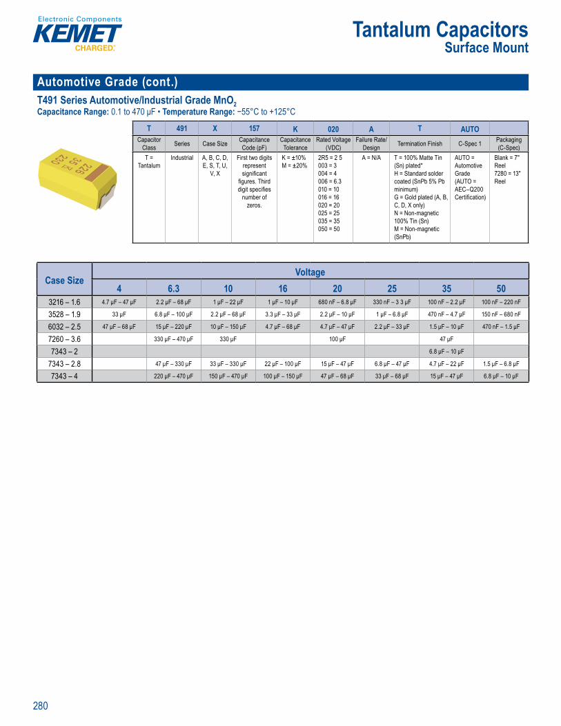
280
Tantalum CapacitorsSurface Mount
Automotive Grade (cont.) T491 Series Automotive/Industrial Grade MnO2 Capacitance Range: 0.1 to 470 μF • Temperature Range: −55°C to +125°C
's SP CE softw re.
Ord r g n
T 491 X 157 K 020 A T AUTOCapacitor
Class Series Case Size Capacitance Code (pF)
Capacitance Tolerance
Rated Voltage (VDC)
Failure Rate/Design Termination Finish C-Spec 1 Packaging
(C-Spec)T =
TantalumIndustrial A, B, C, D,
E, S, T, U, V, X
First two digits represent signifi cant
fi gures. Third digit specifi es
number of zeros.
K = ±10%M = ±20%
2R5 = 2 5 003 = 3 004 = 4 006 = 6.3 010 = 10 016 = 16 020 = 20 025 = 25 035 = 35 050 = 50
A = N/A T = 100% Matte Tin (Sn) plated* H = Standard solder coated (SnPb 5% Pb minimum) G = Gold plated (A, B, C, D, X only) N = Non-magnetic 100% Tin (Sn)M = Non-magnetic (SnPb)
AUTO = Automotive Grade(AUTO = AEC–Q200 Certifi cation)
Blank = 7" Reel 7280 = 13" Reel
Case SizeVoltage
4 6.3 10 16 20 25 35 503216 – 1.6 4.7 μF – 47 μF 2.2 μF – 68 μF 1 μF – 22 μF 1 μF – 10 μF 680 nF – 6.8 μF 330 nF – 3 3 μF 100 nF – 2.2 μF 100 nF – 220 nF
3528 – 1.9 33 μF 6.8 μF – 100 μF 2.2 μF – 68 μF 3.3 μF – 33 μF 2.2 μF – 10 μF 1 μF – 6.8 μF 470 nF – 4.7 μF 150 nF – 680 nF
6032 – 2.5 47 μF – 68 μF 15 μF – 220 μF 10 μF – 150 μF 4.7 μF – 68 μF 4.7 μF – 47 μF 2.2 μF – 33 μF 1.5 μF – 10 μF 470 nF – 1.5 μF
7260 – 3.6 330 μF – 470 μF 330 μF 100 μF 47 μF
7343 – 2 6.8 μF – 10 μF
7343 – 2.8 47 μF – 330 μF 33 μF – 330 μF 22 μF – 100 μF 15 μF – 47 μF 6.8 μF – 47 μF 4.7 μF – 22 μF 1.5 μF – 6.8 μF
7343 – 4 220 μF – 470 μF 150 μF – 470 μF 100 μF – 150 μF 47 μF – 68 μF 33 μF – 68 μF 15 μF – 47 μF 6.8 μF – 10 μF
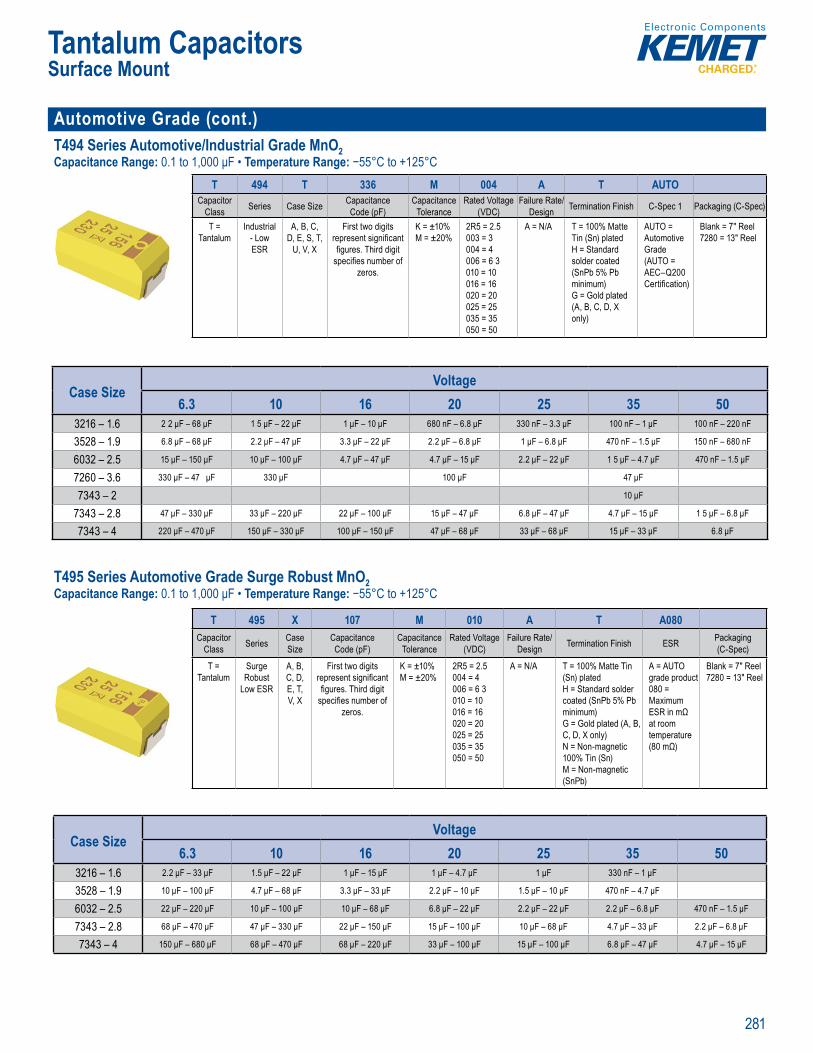
281
Tantalum CapacitorsSurface Mount
Automotive Grade (cont.)T494 Series Automotive/Industrial Grade MnO2 Capacitance Range: 0.1 to 1,000 μF • Temperature Range: −55°C to +125°C
SPICE
O de i I f t
T 494 T 336 M 004 A T AUTOCapacitor
Class Series Case Size Capacitance Code (pF)
Capacitance Tolerance
Rated Voltage (VDC)
Failure Rate/Design Termination Finish C-Spec 1 Packaging (C-Spec)
T = Tantalum
Industrial - Low ESR
A, B, C, D, E, S, T,
U, V, X
First two digits represent signifi cant fi gures. Third digit
specifi es number of zeros.
K = ±10%M = ±20%
2R5 = 2.5 003 = 3 004 = 4 006 = 6 3 010 = 10 016 = 16 020 = 20 025 = 25 035 = 35 050 = 50
A = N/A T = 100% Matte Tin (Sn) platedH = Standard solder coated (SnPb 5% Pb minimum)G = Gold plated (A, B, C, D, X only)
AUTO = Automotive Grade (AUTO = AEC–Q200 Certifi cation)
Blank = 7" Reel 7280 = 13" Reel
Case SizeVoltage
6.3 10 16 20 25 35 503216 – 1.6 2 2 μF – 68 μF 1 5 μF – 22 μF 1 μF – 10 μF 680 nF – 6.8 μF 330 nF – 3.3 μF 100 nF – 1 μF 100 nF – 220 nF
3528 – 1.9 6.8 μF – 68 μF 2.2 μF – 47 μF 3.3 μF – 22 μF 2.2 μF – 6.8 μF 1 μF – 6.8 μF 470 nF – 1.5 μF 150 nF – 680 nF
6032 – 2.5 15 μF – 150 μF 10 μF – 100 μF 4.7 μF – 47 μF 4.7 μF – 15 μF 2.2 μF – 22 μF 1 5 μF – 4.7 μF 470 nF – 1.5 μF
7260 – 3.6 330 μF – 47 μF 330 μF 100 μF 47 μF
7343 – 2 10 μF
7343 – 2.8 47 μF – 330 μF 33 μF – 220 μF 22 μF – 100 μF 15 μF – 47 μF 6.8 μF – 47 μF 4.7 μF – 15 μF 1 5 μF – 6.8 μF
7343 – 4 220 μF – 470 μF 150 μF – 330 μF 100 μF – 150 μF 47 μF – 68 μF 33 μF – 68 μF 15 μF – 33 μF 6.8 μF T495 Series Automotive Grade Surge Robust MnO2 Capacitance Range: 0.1 to 1,000 μF • Temperature Range: −55°C to +125°C
T nt ou Capa ot G a4 5 omotiv Grade ust Low ESR
SPIC
e C l t c t
fre u m er t re ri D s on
rd I f r
T 495 X 107 M 010 A T A080Capacitor
Class Series Case Size
Capacitance Code (pF)
Capacitance Tolerance
Rated Voltage(VDC)
Failure Rate/ Design Termination Finish ESR Packaging
(C-Spec)
T = Tantalum
Surge Robust
Low ESR
A, B, C, D, E, T, V, X
First two digits represent signifi cant fi gures. Third digit
specifi es number of zeros.
K = ±10%M = ±20%
2R5 = 2.5 004 = 4 006 = 6 3 010 = 10 016 = 16 020 = 20 025 = 25 035 = 35 050 = 50
A = N/A T = 100% Matte Tin (Sn) platedH = Standard solder coated (SnPb 5% Pb minimum)G = Gold plated (A, B, C, D, X only)N = Non-magnetic 100% Tin (Sn) M = Non-magnetic (SnPb)
A = AUTO grade product080 = Maximum ESR in mΩ at room temperature (80 mΩ)
Blank = 7" Reel 7280 = 13" Reel
Case SizeVoltage
6.3 10 16 20 25 35 503216 – 1.6 2.2 μF – 33 μF 1.5 μF – 22 μF 1 μF – 15 μF 1 μF – 4.7 μF 1 μF 330 nF – 1 μF
3528 – 1.9 10 μF – 100 μF 4.7 μF – 68 μF 3.3 μF – 33 μF 2.2 μF – 10 μF 1.5 μF – 10 μF 470 nF – 4.7 μF
6032 – 2.5 22 μF – 220 μF 10 μF – 100 μF 10 μF – 68 μF 6.8 μF – 22 μF 2.2 μF – 22 μF 2.2 μF – 6.8 μF 470 nF – 1.5 μF
7343 – 2.8 68 μF – 470 μF 47 μF – 330 μF 22 μF – 150 μF 15 μF – 100 μF 10 μF – 68 μF 4.7 μF – 33 μF 2.2 μF – 6.8 μF
7343 – 4 150 μF – 680 μF 68 μF – 470 μF 68 μF – 220 μF 33 μF – 100 μF 15 μF – 100 μF 6.8 μF – 47 μF 4.7 μF – 15 μF
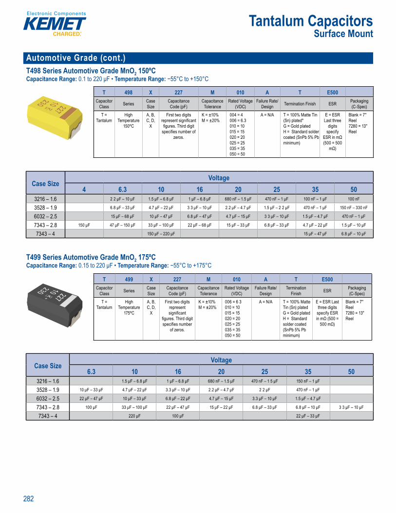
282
Tantalum CapacitorsSurface Mount
Automotive Grade (cont.)T498 Series Automotive Grade MnO2 150ºCCapacitance Range: 0.1 to 220 μF • Temperature Range: −55°C to +150°C
s SP CE softw re The
Order g nf mation
T 498 X 227 M 010 A T E500Capacitor
Class Series Case Size
Capacitance Code (pF)
Capacitance Tolerance
Rated Voltage (VDC)
Failure Rate/Design Termination Finish ESR Packaging
(C-Spec)
T = Tantalum
High Temperature
150ºC
A, B, C, D,
X
First two digits represent signifi cant fi gures. Third digit
specifi es number of zeros.
K = ±10%M = ±20%
004 = 4006 = 6.3 010 = 10 015 = 15 020 = 20025 = 25 035 = 35 050 = 50
A = N/A T = 100% Matte Tin (Sn) plated* G = Gold platedH = Standard solder coated (SnPb 5% Pb minimum)
E = ESR Last three
digits specify
ESR in mΩ (500 = 500
mΩ)
Blank = 7" Reel7280 = 13" Reel
Case SizeVoltage
4 6.3 10 16 20 25 35 503216 – 1.6 2 2 μF – 10 μF 1.5 μF – 6.8 μF 1 μF – 6.8 μF 680 nF – 1.5 μF 470 nF – 1 μF 100 nF – 1 μF 100 nF
3528 – 1.9 6.8 μF – 33 μF 4.7 μF – 22 μF 3 3 μF – 10 μF 2.2 μF – 4.7 μF 1.5 μF – 2 2 μF 470 nF – 1 μF 150 nF – 330 nF
6032 – 2.5 15 μF – 68 μF 10 μF – 47 μF 6.8 μF – 47 μF 4.7 μF – 15 μF 3 3 μF – 10 μF 1.5 μF – 4.7 μF 470 nF – 1 μF
7343 – 2.8 150 μF 47 μF – 150 μF 33 μF – 100 μF 22 μF – 68 μF 15 μF – 33 μF 6.8 μF – 33 μF 4.7 μF – 22 μF 1.5 μF – 10 μF
7343 – 4 150 μF – 220 μF 15 μF – 47 μF 6.8 μF – 10 μF
T499 Series Automotive Grade MnO2 175ºCCapacitance Range: 0.15 to 220 μF • Temperature Range: −55°C to +175°C
ac M Aut
tai e nalys peci c pa t n s, please vi . emet com ree downloa EME s I tware. he f r te t s ca a fr
rde in Informa ion
T 499 X 227 M 010 A T E500Capacitor
Class Series Case Size
Capacitance Code (pF)
Capacitance Tolerance
Rated Voltage (VDC)
Failure Rate/Design
Termination Finish ESR Packaging
(C-Spec)
T = Tantalum
High Temperature
175ºC
A, B, C, D,
X
First two digits represent signifi cant
fi gures. Third digit specifi es number
of zeros.
K = ±10%M = ±20%
006 = 6 3010 = 10015 = 15020 = 20025 = 25035 = 35050 = 50
A = N/A T = 100% Matte Tin (Sn) platedG = Gold platedH = Standard solder coated (SnPb 5% Pb minimum)
E = ESR Last three digits
specify ESR in mΩ (500 =
500 mΩ)
Blank = 7" Reel7280 = 13" Reel
Case SizeVoltage
6.3 10 16 20 25 35 503216 – 1.6 1.5 μF – 6.8 μF 1 μF – 6.8 μF 680 nF – 1.5 μF 470 nF – 1 5 μF 150 nF – 1 μF
3528 – 1.9 10 μF – 33 μF 4.7 μF – 22 μF 3.3 μF – 10 μF 2.2 μF – 4.7 μF 2 2 μF 470 nF – 1 μF
6032 – 2.5 22 μF – 47 μF 10 μF – 33 μF 6.8 μF – 22 μF 4.7 μF – 15 μF 3.3 μF – 10 μF 1.5 μF – 4.7 μF
7343 – 2.8 100 μF 33 μF – 100 μF 22 μF – 47 μF 15 μF – 22 μF 6.8 μF – 33 μF 6.8 μF – 10 μF 3 3 μF – 10 μF
7343 – 4 220 μF 100 μF 22 μF – 33 μF
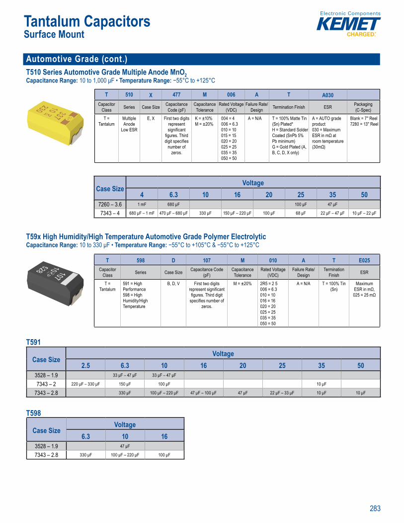
283
Tantalum CapacitorsSurface Mount
Automotive Grade (cont.)T510 Series Automotive Grade Multiple Anode MnO2 Capacitance Range: 10 to 1,000 μF • Temperature Range: −55°C to +125°C
SPICE
Orde in Information
T 510 X 477 M 006 A T A030Capacitor
Class Series Case Size Capacitance Code (pF)
Capacitance Tolerance
Rated Voltage(VDC)
Failure Rate/Design Termination Finish ESR Packaging
(C-Spec)
T = Tantalum
Multiple Anode
Low ESR
E, X First two digits represent signifi cant
fi gures. Third digit specifi es
number of zeros.
K = ±10%M = ±20%
004 = 4006 = 6.3 010 = 10015 = 15 020 = 20 025 = 25035 = 35050 = 50
A = N/A T = 100% Matte Tin (Sn) Plated* H = Standard Solder Coated (SnPb 5% Pb minimum) G = Gold Plated (A, B, C, D, X only)
A = AUTO grade product030 = Maximum ESR in mΩ at room temperature (30mΩ)
Blank = 7" Reel7280 = 13" Reel
Case SizeVoltage
4 6.3 10 16 20 25 35 507260 – 3.6 1 mF 680 μF 100 μF 47 μF
7343 – 4 680 μF – 1 mF 470 μF – 680 μF 330 μF 150 μF – 220 μF 100 μF 68 μF 22 μF – 47 μF 10 μF – 22 μF T59x High Humidity/High Temperature Automotive Grade Polymer ElectrolyticCapacitance Range: 10 to 330 μF • Temperature Range: −55°C to +105°C & −55°C to +125°C
Orderi g Info mation
T 598 D 107 M 010 A T E025Capacitor
Class Series Case Size Capacitance Code (pF)
Capacitance Tolerance
Rated Voltage (VDC)
Failure Rate/ Design
TerminationFinish ESR
T = Tantalum
591 = High Performance598 = High Humidity/High Temperature
B, D, V First two digits represent signifi cant fi gures. Third digit
specifi es number of zeros.
M = ±20% 2R5 = 2 5006 = 6.3010 = 10016 = 16020 = 20025 = 25035 = 35050 = 50
A = N/A T = 100% Tin (Sn)
Maximum ESR in mΩ, 025 = 25 mΩ
T591
Case SizeVoltage
2.5 6.3 10 16 20 25 35 503528 – 1.9 33 μF – 47 μF 33 μF – 47 μF
7343 – 2 220 μF – 330 μF 150 μF 100 μF 10 μF
7343 – 2.8 330 μF 100 μF – 220 μF 47 μF – 100 μF 47 μF 22 μF – 33 μF 10 μF 10 μF
T598
Case SizeVoltage
6.3 10 163528 – 1.9 47 μF
7343 – 2.8 330 μF 100 μF – 220 μF 100 μF

284
Tantalum CapacitorsSurface Mount
Space Grade T493 Series Space Grade (COTS) MnO2 (CWR11 Style)Capacitance Range: 0.1 to 330 μF • Temperature Range: −55°C to +125°C
's SPICE softw re. The
O er g I t n
T 493 D 227 K 006 C H 61 2 ACapacitor
Class Series Case Size
Capacitance Code (pF)
Capacitance Tolerance Voltage Failure Rate/
Design Lead Material Surge ESR Testing
T = Tantalum
CRW11 Style
Space Grade
A, B, C, D,
X
First two digits represent signifi cant
fi gures. Third digit specifi es
number of zeros.
J = ±5% K = ±10% M = ±20%
004 = 4 V 006 = 6 3 V 010 = 10 V 016 = 16 V 020 = 20 V 025 = 25 V 035 = 35 V 050 = 50 V
C = .01%/1,000
hours
C = Hot Solder Dipped H = Standard Solder Coated (SnPb 5% Pb minimum)B = Gold Plated K = Solder Fused T = 100% Tin
61 = None 62 = 10 Cycles after Weibull,25 C 63 = 10 Cycles, after Weibull,-55 C and 85 C 64 = 10 Cycles before Weibull, -55 C and 85 C65 = 10 Cycles Before and After Weibull, -55 C and 85 C
1 = ESR - Standard2 = ESR - Low
A = Option AB = Option BC = Option C
Case SizeVoltage
4 6.3 10 16 20 25 35 503216 – 1.6 2.2 μF – 22 μF 1.5 μF – 15 μF 1 μF – 10 μF 680 nF – 2 2 μF 470 nF – 1 μF 330 nF – 1.5 μF 100 nF – 680 nF 100 nF – 150 nF
3528 – 1.9 6.8 μF – 68 μF 4.7 μF – 47 μF 3.3 μF – 22 μF 3 3 μF – 6.8 μF 1.5 μF – 3.3 μF 680 nF – 3 3 μF 470 nF – 2.2 μF 150 nF – 470 nF
6032 – 2.5 22 μF – 150 μF 15 μF – 100 μF 10 μF – 68 μF 6.8 μF – 22 μF 4.7 μF – 15 μF 2 2 μF – 15 μF 1.5 μF – 4.7 μF 470 nF – 2.2 μF
7343 – 2.8 68 μF – 330 μF 47 μF – 330 μF 33 μF – 220 μF 22 μF – 68 μF 15 μF – 33 μF 6.8 μF – 22 μF 4.7 μF – 15 μF 1 5 μF – 4.7 μF
7343 – 4 330 μF 220 μF – 330 μF 68 μF – 330 μF 100 μF 47 μF – 68 μF 15 μF – 33 μF 10 μF – 22 μF 4.7 μF – 10 μF
T496 Series Space Grade Fail-Safe Fused MnO2 Capacitance Range: 0.15 to 470 μF • Temperature Range: −55°C to +125°C
p ace u e
S
o tai e ly p ci a t s le v . em t f ee nlo E E I tw r
t i
rde in Informa ion
T 496 X 227 M 010 C T 61 2 ACapacitor
Class Series Case Size
Capacitance Code (pF)
Capacitance Tolerance Voltage Failure Rate/
Design Lead Material Surge ESR Testing
T = Tantalum
Fail Safe - Space Grade
B, C, D, X
First two digits represent signifi cant
fi gures. Third digit specifi es
number of zeros.
K = ±10%M = ±20%
004 = 4 V006 = 6.3 V010 = 10 V 016 = 16 V 020 = 20 V 025 = 25 V 035 = 35 V 050 = 50 V
C = 0.01%/1,000
hours
C = Hot Solder Dipped T = 100% Matte Tin (Sn) Plated H = Standard Solder Coated (SnPb 5% Pb minimum)
61 = None 62 = 10 Cycles after Weibull,25 C 63 = 10 Cycles, after Weibull,-55 C and 85 C64 = 10 Cycles before Weibull, -55 C and 85 C65 = 10 Cycles Before and After Weibull, -55 C and 85 C
1 = ESR - Standard2 = ESR - Low
A = Option AB = Option BC = Option C
Case SizeVoltage
4 6.3 10 16 20 25 35 503528 – 1.9 4.7 μF – 22 μF 3.3 μF – 15 μF 2.2 μF – 4.7 μF 1.5 μF – 2.2 μF 680 nF – 4.7 μF 470 nF – 1 μF 150 nF – 330 nF
6032 – 2.5 68 μF – 150 μF 15 μF – 100 μF 10 μF – 47 μF 6.8 μF – 22 μF 4.7 μF – 15 μF 2 2 μF – 15 μF 1.5 μF – 3.3 μF 470 nF – 1.5 μF
7343 – 2.8 150 μF – 330 μF 47 μF – 220 μF 33 μF – 150 μF 22 μF – 68 μF 15 μF – 33 μF 10 μF – 22 μF 4.7 μF – 15 μF 2 2 μF – 4.7 μF
7343 – 4 330 μF – 470 μF 100 μF – 330 μF 68 μF – 220 μF 47 μF 33 μF 22 μF 10 μF – 15 μF 4.7 μF
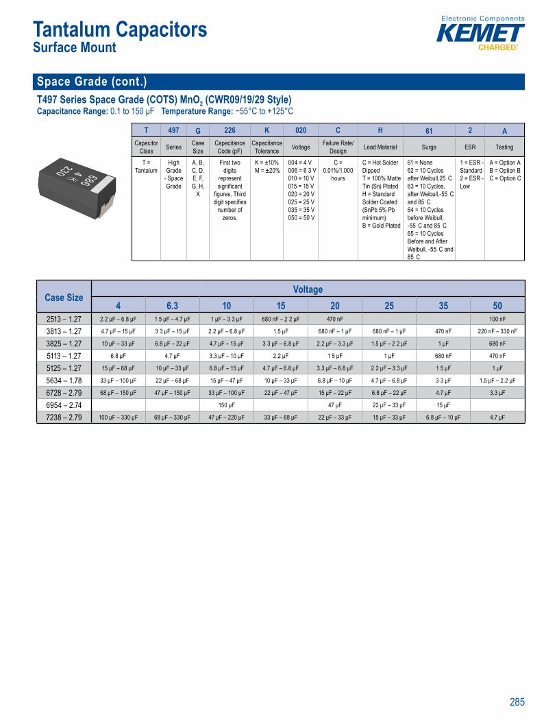
285
Tantalum CapacitorsSurface Mount
Space Grade (cont.)T497 Series Space Grade (COTS) MnO2 (CWR09/19/29 Style)Capacitance Range: 0.1 to 150 μF Temperature Range: −55°C to +125°C
SPICE
rder ng nfo mation
T 497 G 226 K 020 C H 61 2 ACapacitor
Class Series Case Size
CapacitanceCode (pF)
Capacitance Tolerance Voltage Failure Rate/
Design Lead Material Surge ESR Testing
T = Tantalum
High Grade
- Space Grade
A, B, C, D, E, F, G, H,
X
First two digits
represent signifi cant
fi gures. Third digit specifi es
number of zeros.
K = ±10%M = ±20%
004 = 4 V006 = 6 3 V010 = 10 V015 = 15 V020 = 20 V025 = 25 V035 = 35 V050 = 50 V
C = 0.01%/1,000
hours
C = Hot Solder Dipped T = 100% Matte Tin (Sn) PlatedH = Standard Solder Coated (SnPb 5% Pb minimum) B = Gold Plated
61 = None 62 = 10 Cycles after Weibull,25 C 63 = 10 Cycles, after Weibull,-55 C and 85 C 64 = 10 Cycles before Weibull, -55 C and 85 C65 = 10 Cycles Before and After Weibull, -55 C and 85 C
1 = ESR - Standard 2 = ESR - Low
A = Option AB = Option BC = Option C
Case SizeVoltage
4 6.3 10 15 20 25 35 502513 – 1.27 2.2 μF – 6.8 μF 1 5 μF – 4.7 μF 1 μF – 3 3 μF 680 nF – 2 2 μF 470 nF 100 nF
3813 – 1.27 4.7 μF – 15 μF 3 3 μF – 15 μF 2.2 μF – 6.8 μF 1.5 μF 680 nF – 1 μF 680 nF – 1 μF 470 nF 220 nF – 330 nF
3825 – 1.27 10 μF – 33 μF 6.8 μF – 22 μF 4.7 μF – 15 μF 3 3 μF – 6.8 μF 2.2 μF – 3.3 μF 1.5 μF – 2 2 μF 1 μF 680 nF
5113 – 1.27 6.8 μF 4.7 μF 3.3 μF – 10 μF 2.2 μF 1 5 μF 1 μF 680 nF 470 nF
5125 – 1.27 15 μF – 68 μF 10 μF – 33 μF 6.8 μF – 15 μF 4.7 μF – 6.8 μF 3.3 μF – 6.8 μF 2 2 μF – 3.3 μF 1 5 μF 1 μF
5634 – 1.78 33 μF – 100 μF 22 μF – 68 μF 15 μF – 47 μF 10 μF – 33 μF 6.8 μF – 10 μF 4.7 μF – 6.8 μF 3 3 μF 1.5 μF – 2.2 μF
6728 – 2.79 68 μF – 150 μF 47 μF – 150 μF 33 μF – 100 μF 22 μF – 47 μF 15 μF – 22 μF 6.8 μF – 22 μF 4.7 μF 3.3 μF
6954 – 2.74 150 μF 47 μF 22 μF – 33 μF 15 μF
7238 – 2.79 100 μF – 330 μF 68 μF – 330 μF 47 μF – 220 μF 33 μF – 68 μF 22 μF – 33 μF 15 μF – 33 μF 6.8 μF – 10 μF 4.7 μF
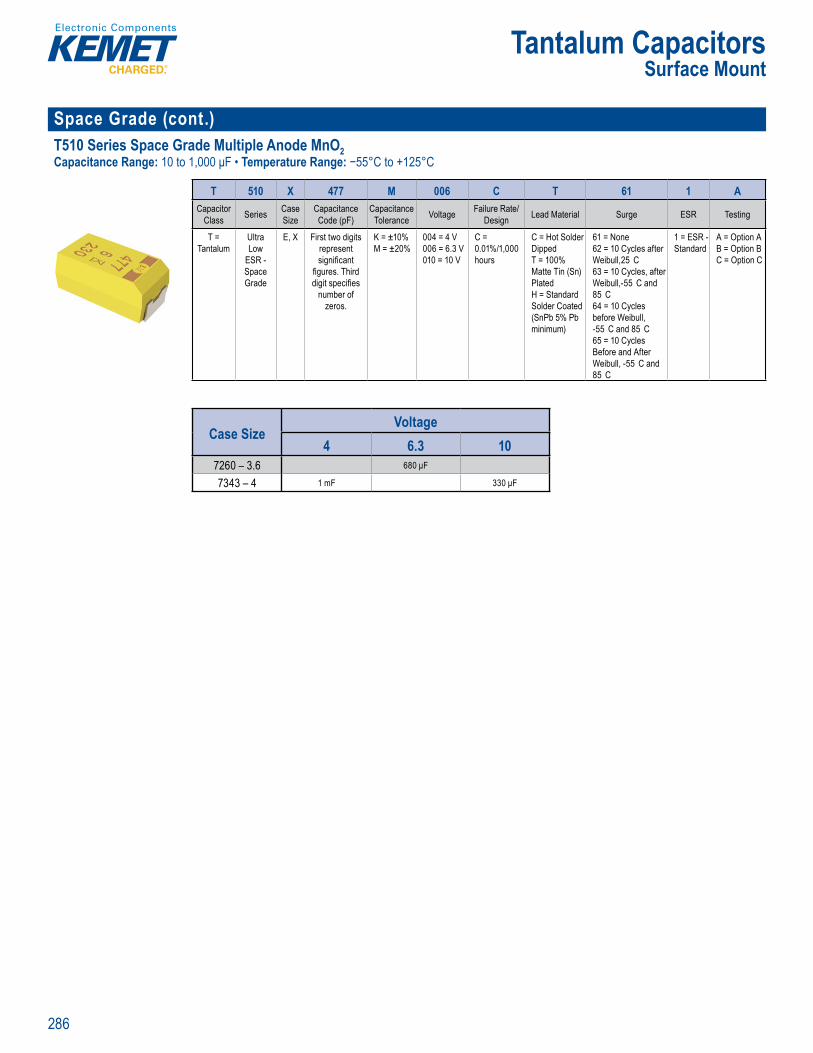
286
Tantalum CapacitorsSurface Mount
Space Grade (cont.)T510 Series Space Grade Multiple Anode MnO2 Capacitance Range: 10 to 1,000 μF • Temperature Range: −55°C to +125°C
's SP CE softw re
Orde in Information
T 510 X 477 M 006 C T 61 1 ACapacitor
Class Series Case Size
Capacitance Code (pF)
Capacitance Tolerance Voltage Failure Rate/
Design Lead Material Surge ESR Testing
T = Tantalum
Ultra Low
ESR - Space Grade
E, X First two digits represent signifi cant
fi gures. Third digit specifi es
number of zeros.
K = ±10%M = ±20%
004 = 4 V 006 = 6.3 V 010 = 10 V
C = 0.01%/1,000 hours
C = Hot Solder Dipped T = 100% Matte Tin (Sn) PlatedH = Standard Solder Coated (SnPb 5% Pb minimum)
61 = None 62 = 10 Cycles after Weibull,25 C 63 = 10 Cycles, after Weibull,-55 C and 85 C64 = 10 Cycles before Weibull, -55 C and 85 C65 = 10 Cycles Before and After Weibull, -55 C and 85 C
1 = ESR - Standard
A = Option A B = Option B C = Option C
Case SizeVoltage
4 6.3 107260 – 3.6 680 μF
7343 – 4 1 mF 330 μF
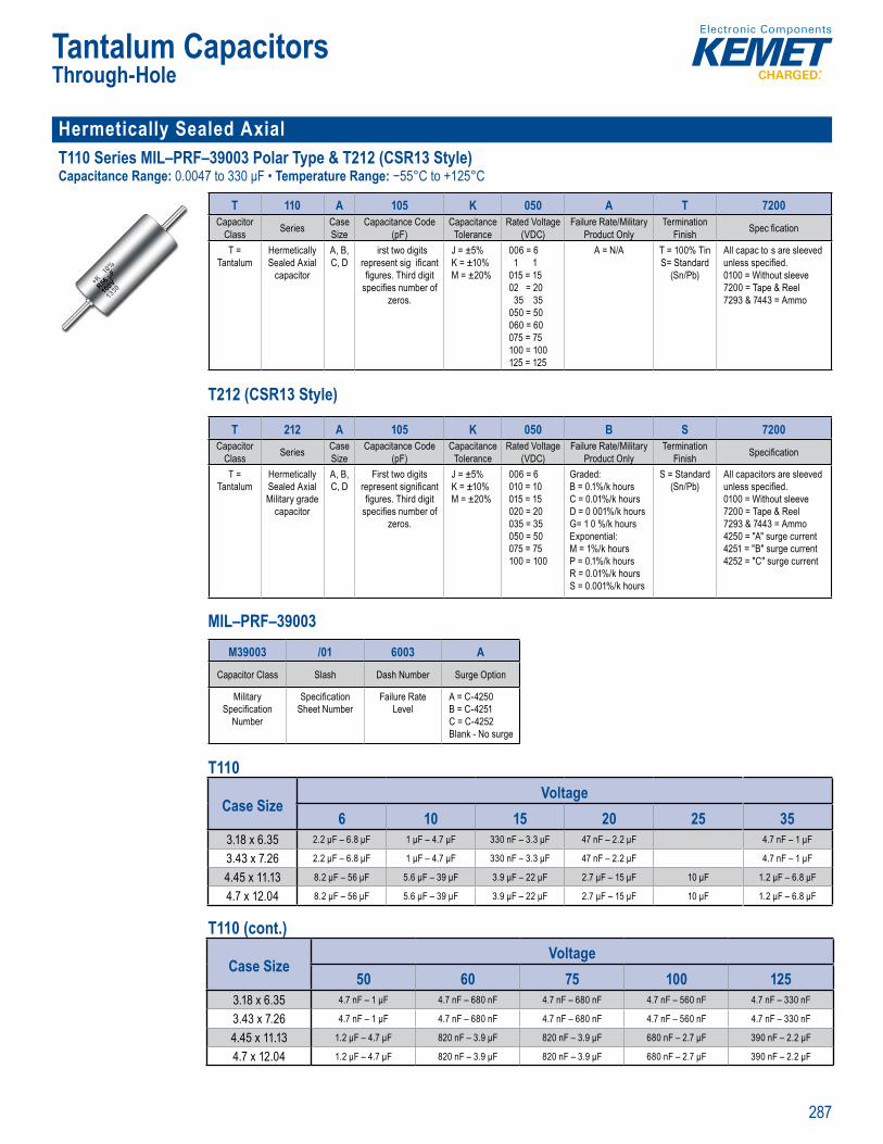
287
Tantalum CapacitorsThrough-Hole
Hermetically Sealed AxialT110 Series MIL–PRF–39003 Polar Type & T212 (CSR13 Style)Capacitance Range: 0.0047 to 330 μF • Temperature Range: −55°C to +125°C
11 S ies Axial M
O eri g f rmat on T 10
T 110 A 105 K 050 A T 7200Capacitor
Class Series Case Size
Capacitance Code (pF)
Capacitance Tolerance
Rated Voltage(VDC)
Failure Rate/Military Product Only
Termination Finish Spec fi cation
T = Tantalum
Hermetically Sealed Axial
capacitor
A, B, C, D
irst two digits represent sig ifi cant fi gures. Third digit
specifi es number of zeros.
J = ±5% K = ±10% M = ±20%
006 = 6 1 1
015 = 1502 = 20
35 35050 = 50060 = 60075 = 75100 = 100125 = 125
A = N/A T = 100% Tin S= Standard
(Sn/Pb)
All capac to s are sleeved unless specifi ed. 0100 = Without sleeve 7200 = Tape & Reel7293 & 7443 = Ammo
T212 (CSR13 Style)
g
T 110 05
a er iz
p )
ra
VDC
uct
i cifi a
T = ntalu
e c
capacitor
A B C D
First two d g ts nt ig
fi gures h rd dig spec fi es number of
z ros
J = ±5% = ±10%
M ±20
006 = 6 = 10
0 5 1020 = 200 5 5050 50060 = 60075 7500 1025 12
A = N/A = 100% T Stand Sn/ b)
pac t rs are sl
01 0 = Without sleeve 7200 = Tape & R7293 & 443 = Ammo
MIL pr duct
T 212 A 105 K 050 B S 7200Capacitor
Class Series Case Size
Capacitance Code (pF)
Capacitance Tolerance
Rated Voltage(VDC)
Failure Rate/Military Product Only
Termination Finish Specifi cation
T = Tantalum
Hermetically Sealed Axial Military grade
capacitor
A, B, C, D
First two digits represent signifi cant fi gures. Third digit
specifi es number of zeros.
J = ±5% K = ±10% M = ±20%
006 = 6010 = 10015 = 15020 = 20035 = 35050 = 50075 = 75100 = 100
Graded:B = 0.1%/k hours C = 0.01%/k hours D = 0 001%/k hoursG= 1 0 %/k hoursExponential:M = 1%/k hours P = 0.1%/k hours R = 0.01%/k hours S = 0.001%/k hours
S = Standard (Sn/Pb)
All capacitors are sleeved unless specifi ed. 0100 = Without sleeve 7200 = Tape & Reel 7293 & 7443 = Ammo4250 = "A" surge current4251 = "B" surge current 4252 = "C" surge current
MIL–PRF–39003
Orde ing nf
T 0 105Ca a itor Cas Capaci ance Code Capa tan
Tant lu
eti
apacito
C, D
wo p e ent sig i an Thi
zero
5 K ±1 M ±2
= 6 1 =
= 15
35 3
0 75 7500 025
N 0 = Standar
n/ b
ors ar
Without slee
72 3 & 7443 = mm
ac s er e a anc
(p )cit a
d Vo)
at d c Only
n cifi cat
metica
Milit g de it
A, B
two
Th d dig p fi u f
= ±5
M 2
=
1 1
5 55 575 75
de :
C k D / G E n t l:
1 k P %/k
1 / /
Stand )
pacitors are sl
1 = W t ut l 72 T p R
7 4 425 A" ur e cu25
4252 C g t
Ordering nforma
M39003 /01 6003 ACapacitor Class Slash Dash Number Surge Option
Military Specifi cation
Number
Specifi cation Sheet Number
Failure Rate Level
A = C-4250B = C-4251C = C-4252Blank - No surge
T110
Case SizeVoltage
6 10 15 20 25 353.18 x 6.35 2.2 μF – 6.8 μF 1 μF – 4.7 μF 330 nF – 3.3 μF 47 nF – 2.2 μF 4.7 nF – 1 μF
3.43 x 7.26 2.2 μF – 6.8 μF 1 μF – 4.7 μF 330 nF – 3.3 μF 47 nF – 2.2 μF 4.7 nF – 1 μF
4.45 x 11.13 8.2 μF – 56 μF 5.6 μF – 39 μF 3.9 μF – 22 μF 2.7 μF – 15 μF 10 μF 1.2 μF – 6.8 μF
4.7 x 12.04 8.2 μF – 56 μF 5.6 μF – 39 μF 3.9 μF – 22 μF 2.7 μF – 15 μF 10 μF 1.2 μF – 6.8 μF
T110 (cont.)
Case SizeVoltage
50 60 75 100 1253.18 x 6.35 4.7 nF – 1 μF 4.7 nF – 680 nF 4.7 nF – 680 nF 4.7 nF – 560 nF 4.7 nF – 330 nF
3.43 x 7.26 4.7 nF – 1 μF 4.7 nF – 680 nF 4.7 nF – 680 nF 4.7 nF – 560 nF 4.7 nF – 330 nF
4.45 x 11.13 1.2 μF – 4.7 μF 820 nF – 3.9 μF 820 nF – 3.9 μF 680 nF – 2.7 μF 390 nF – 2.2 μF
4.7 x 12.04 1.2 μF – 4.7 μF 820 nF – 3.9 μF 820 nF – 3.9 μF 680 nF – 2.7 μF 390 nF – 2.2 μF

288
Tantalum CapacitorsThrough-Hole
Hermetically Sealed Axial (cont.)T110 Series MIL–PRF–39003 Polar Type & T212 (CSR13 Style) (cont.)Capacitance Range: 0.0047 to 330 μF • Temperature Range: −55°C to +125°C
11 S ies Axial M –PRF–390 3 P
O eri g f rmat on T 10
T 110 A 105 K 050 A T 7200Capacitor
Class Series Case Size
Capacitance Code (pF)
Capacitance Tolerance
Rated Voltage(VDC)
Failure Rate/Military Product Only
Termination Finish Spec fi cation
T = Tantalum
Hermetically Sealed Axial
capacitor
A, B, C, D
irst two digits represent sig ifi cant fi gures. Third digit
specifi es number of zeros.
J = ±5% K = ±10% M = ±20%
006 = 6 1 1
015 = 1502 = 20
35 35050 = 50060 = 60075 = 75100 = 100125 = 125
A = N/A T = 100% Tin S= Standard
(Sn/Pb)
All capac to s are sleeved unless specifi ed. 0100 = Without sleeve 7200 = Tape & Reel7293 & 7443 = Ammo
T212 (CSR13 Style)
g
T 110 05
a er iz
p )
ra
VDC
uct
i cifi a
T = ntalu
e c
capacitor
A B C D
First two d g ts nt ig
fi gures h rd dig spec fi es number of
z ros
J = ±5% = ±10%
M ±20
006 = 6 = 10
0 5 1020 = 200 5 5050 50060 = 60075 7500 1025 12
A = N/A = 100% T Stand Sn/ b)
pac t rs are sl
01 0 = Without sleeve 7200 = Tape & R7293 & 443 = Ammo
MIL pr duct
T 212 A 105 K 050 B S 7200Capacitor
Class Series Case Size
Capacitance Code (pF)
Capacitance Tolerance
Rated Voltage(VDC)
Failure Rate/Military Product Only
Termination Finish Specifi cation
T = Tantalum
Hermetically Sealed Axial Military grade
capacitor
A, B, C, D
First two digits represent signifi cant fi gures. Third digit
specifi es number of zeros.
J = ±5% K = ±10% M = ±20%
006 = 6010 = 10015 = 15020 = 20035 = 35050 = 50075 = 75100 = 100
Graded:B = 0.1%/k hours C = 0.01%/k hours D = 0 001%/k hoursG= 1 0 %/k hoursExponential:M = 1%/k hours P = 0.1%/k hours R = 0.01%/k hours S = 0.001%/k hours
S = Standard (Sn/Pb)
All capacitors are sleeved unless specifi ed. 0100 = Without sleeve 7200 = Tape & Reel 7293 & 7443 = Ammo4250 = "A" surge current4251 = "B" surge current 4252 = "C" surge current
MIL–PRF–39003
Orde ing nf rma io –
T 0 105Ca a itor Cas Capaci ance Code Capa tan
Tant lu
eti
apacito
C, D
wo p e ent sig i an Thi
zero
5 K ±1 M ±2
= 6 1 =
= 15
35 3
0 75 7500 025
N 0 = Standar
n/ b
ors ar
Without slee
72 3 & 7443 = mm
ac s er e a anc
(p )cit a
d Vo)
at d c Only
n cifi cat
metica
Milit g de it
A, B
two
Th d dig p fi u f
= ±5
M 2
=
1 1
5 55 575 75
de :
C k D / G E n t l:
1 k P %/k
1 / /
Stand )
pacitors are sl
1 = W t ut l 72 T p R
7 4 425 A" ur e cu25
4252 C g t
Ordering nforma
M39003 /01 6003 ACapacitor Class Slash Dash Number Surge Option
Military Specifi cation
Number
Specifi cation Sheet Number
Failure Rate Level
A = C-4250B = C-4251C = C-4252Blank - No surge
T212 (CSR13 Style)
Case SizeVoltage
6 10 15 20 35 50 75 1003.18 x 6.35 5.6 μF – 6.8 μF 3.9 μF – 4.7 μF 2.7 μF – 3.3 μF 1.2 μF – 2 2 μF 4.7 nF – 1 μF 100 nF – 680 nF 4.7 nF – 560 nF
3.43 x 7.26 5.6 μF – 6.8 μF 3.9 μF – 4.7 μF 2.7 μF – 3.3 μF 1.2 μF – 2 2 μF 4.7 nF – 1 μF 100 nF – 680 nF 4.7 nF – 560 nF
4.45 x 11.13 47 μF – 56 μF 27 μF – 39 μF 18 μF – 22 μF 8 2 μF – 15 μF 5.6 μF – 6.8 μF 1.2 μF – 4.7 μF 820 nF – 3.9 μF 680 nF – 2.7 μF
4.7 x 12.04 47 μF – 56 μF 27 μF – 39 μF 18 μF – 22 μF 8 2 μF – 15 μF 5.6 μF – 6.8 μF 1.2 μF – 4.7 μF 820 nF – 3.9 μF 680 nF – 2.7 μF
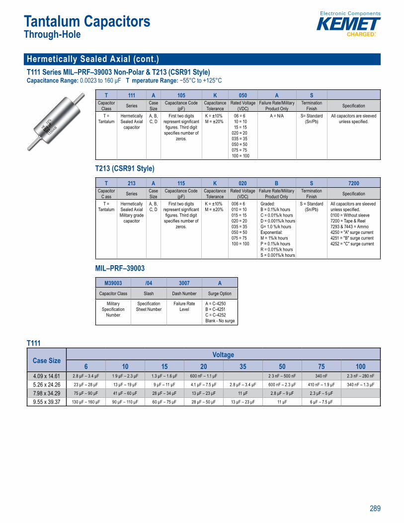
289
Tantalum CapacitorsThrough-Hole
Hermetically Sealed Axial (cont.)T111 Series MIL–PRF–39003 Non-Polar & T213 (CSR91 Style)Capacitance Range: 0.0023 to 160 μF T mperature Range: −55°C to +125°C
u e s 11 S i Axi PRF 9 3 N
Or eri g I formation T 1
T 111 A 105 K 050 A SCapacitor
Class Series Case Size
Capacitance Code (pF)
Capacitance Tolerance
Rated Voltage(VDC)
Failure Rate/Military Product Only
Termination Finish Specifi cation
T = Tantalum
Hermetically Sealed Axial
capacitor
A, B, C, D
First two digits represent signifi cant fi gures. Third digit
specifi es number of zeros.
K = ±10% M = ±20%
06 = 6 10 = 1015 = 15
020 = 20 035 = 35050 = 50 075 = 75 100 = 100
A = N/A S= Standard (Sn/Pb)
All capacitors are sleeved unless specifi ed.
T213 (CSR91 Style)
O d ri nf r a i
1 1 A 05 K
as
z
(
ra
VDC
ni
T n l
aled Ax
A, , C D
t g t
T ec fi es number
zeros
K M 2
020 = 0 5 350 0 = 50 075 7 100 10
S a d S P
nless spec fi e
MIL p odu t
T 213 A 115 K 020 B S 7200Capacitor
C ass Series Case Size
Capacitance Code (pF)
Capacitance Tolerance
Rated Voltage(VDC)
Failure Rate/Military Product Only
Termination Finish Specifi cation
T = Tantalum
Hermetically Sealed Axial Military grade
capacitor
A, B, C, D
First two digits represent signifi cant fi gures. Third digit
specifi es number of zeros.
K = ±10% M = ±20%
006 = 6010 = 10015 = 15020 = 20035 = 35050 = 50075 = 75100 = 100
Graded:B = 0.1%/k hours C = 0.01%/k hours D = 0.001%/k hoursG= 1.0 %/k hoursExponential:M = 1%/k hours P = 0.1%/k hours R = 0.01%/k hours S = 0.001%/k hours
S = Standard (Sn/Pb)
All capacitors are sleeved unless specifi ed.0100 = Without sleeve 7200 = Tape & Reel 7293 & 7443 = Ammo4250 = "A" surge current 4251 = "B" surge current 4252 = "C" surge current
MIL–PRF–39003
O de ing f r a o –
T 111 A 105Ca acito Ser es C se Capac t ce ode Ca acitan
ed
ap
t i
fi gures Third dig t s nu zeros.
2
= 10
015 = 15 = 20
035 3050 = 50 075 75 00 0
/P
a ass er e a
Sizeanc (pF
cit To e ance
d Vo(V C)
at Product Only
n Finish cifi
T = nt l
i ealed xial
M l t r grade capacitor
A B C
two d present s g i c gu e . Th rd d g t pecifi e num er o
ze os.
= ±10% M ±2 %
= 60
15 150 0 = 0
35 350 0
75 700 0
aded: 0.
C .0 k ur D = 0.001% k ourG 1 /k h u s
x on ntia :M 1 k ou P .1% ur R .0 k ur S k ur
Stand (Sn/ b)
l un ess pecifi ed.10 W t ou
7200 = Tape & Reel 7293 & 7 A m4250 A ur e cur 425 B surg current 4252 C surge current
Ordering forma
M39003 /04 3007 ACapacitor Class Slash Dash Number Surge Option
Military Specifi cation
Number
Specifi cation Sheet Number
Failure Rate Level
A = C-4250B = C-4251C = C-4252Blank - No surge
T111
Case SizeVoltage
6 10 15 20 35 50 75 1004.09 x 14.61 2.8 μF – 3.4 μF 1 9 μF – 2.3 μF 1.3 μF – 1.6 μF 600 nF – 1.1 μF 2 3 nF – 500 nF 340 nF 2.3 nF – 280 nF
5.26 x 24.26 23 μF – 28 μF 13 μF – 19 μF 9 μF – 11 μF 4.1 μF – 7.5 μF 2.8 μF – 3.4 μF 600 nF – 2.3 μF 410 nF – 1.9 μF 340 nF – 1.3 μF
7.98 x 34.29 75 μF – 90 μF 41 μF – 60 μF 28 μF – 34 μF 13 μF – 23 μF 11 μF 2.8 μF – 9 μF 2.3 μF – 5 μF
9.55 x 39.37 130 μF – 160 μF 90 μF – 110 μF 60 μF – 75 μF 28 μF – 50 μF 13 μF – 23 μF 11 μF 6 μF – 7.5 μF
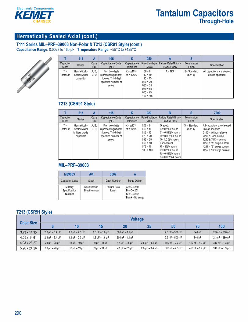
290
Tantalum CapacitorsThrough-Hole
Hermetically Sealed Axial (cont.)T111 Series MIL–PRF–39003 Non-Polar & T213 (CSR91 Style) (cont.)Capacitance Range: 0.0023 to 160 μF T mperature Range: −55°C to +125°C
u e s 11 S i Axi PRF 9 3 N
Or eri g I formation T 1
T 111 A 105 K 050 A SCapacitor
Class Series Case Size
Capacitance Code (pF)
Capacitance Tolerance
Rated Voltage(VDC)
Failure Rate/Military Product Only
Termination Finish Specifi cation
T = Tantalum
Hermetically Sealed Axial
capacitor
A, B, C, D
First two digits represent signifi cant fi gures. Third digit
specifi es number of zeros.
K = ±10% M = ±20%
06 = 6 10 = 1015 = 15
020 = 20 035 = 35050 = 50 075 = 75 100 = 100
A = N/A S= Standard (Sn/Pb)
All capacitors are sleeved unless specifi ed.
T213 (CSR91 Style)
O d ri nf r a i
1 1 A 05 K
as
z
(
ra
VDC
ni
T n l
aled Ax
A, , C D
t g t
T ec fi es number
zeros
K M 2
020 = 0 5 350 0 = 50 075 7 100 10
S a d S P
nless spec fi e
MIL p odu t
T 213 A 115 K 020 B S 7200Capacitor
C ass Series Case Size
Capacitance Code (pF)
Capacitance Tolerance
Rated Voltage(VDC)
Failure Rate/Military Product Only
Termination Finish Specifi cation
T = Tantalum
Hermetically Sealed Axial Military grade
capacitor
A, B, C, D
First two digits represent signifi cant fi gures. Third digit
specifi es number of zeros.
K = ±10% M = ±20%
006 = 6010 = 10015 = 15020 = 20035 = 35050 = 50075 = 75100 = 100
Graded:B = 0.1%/k hours C = 0.01%/k hours D = 0.001%/k hoursG= 1.0 %/k hoursExponential:M = 1%/k hours P = 0.1%/k hours R = 0.01%/k hours S = 0.001%/k hours
S = Standard (Sn/Pb)
All capacitors are sleeved unless specifi ed.0100 = Without sleeve 7200 = Tape & Reel 7293 & 7443 = Ammo4250 = "A" surge current 4251 = "B" surge current 4252 = "C" surge current
MIL–PRF–39003
O de ing f r a o –
T 111 A 105 KCa acito Ser es C se Capac t ce ode Ca acitan
ed
ap
t i
fi gures Third dig t s nu zeros.
2
= 10
015 = 15 = 20
035 3050 = 50 075 75 00 0
/P
a ass er e a
Sizeanc (pF
cit To e ance
d Vo(V C)
at Product Only
n Finish cifi
T = nt l
i ealed xial
M l t r grade capacitor
A B C
two d present s g i c gu e . Th rd d g t pecifi e num er o
ze os.
= ±10% M ±2 %
= 60
15 150 0 = 0
35 350 0
75 700 0
aded: 0.
C .0 k ur D = 0.001% k ourG 1 /k h u s
x on ntia :M 1 k ou P .1% ur R .0 k ur S k ur
Stand (Sn/ b)
l un ess pecifi ed.10 W t ou
7200 = Tape & Reel 7293 & 7 A m4250 A ur e cur 425 B surg current 4252 C surge current
Ordering forma
M39003 /04 3007 ACapacitor Class Slash Dash Number Surge Option
Military Specifi cation
Number
Specifi cation Sheet Number
Failure Rate Level
A = C-4250B = C-4251C = C-4252Blank - No surge
T213 (CSR91 Style)
Case SizeVoltage
6 10 15 20 35 50 75 1003.73 x 14.35 2.8 μF – 3.4 μF 1.9 μF – 2 3 μF 1.3 μF – 1.6 μF 600 nF – 1.1 μF 2.3 nF – 500 nF 340 nF 2.3 nF – 280 nF
4.09 x 14.61 2.8 μF – 3.4 μF 1.9 μF – 2 3 μF 1.3 μF – 1.6 μF 600 nF – 1.1 μF 2.3 nF – 500 nF 340 nF 2.3 nF – 280 nF
4.93 x 23.27 23 μF – 28 μF 13 μF – 19 μF 9 μF – 11 μF 4.1 μF – 7.5 μF 2.8 μF – 3.4 μF 600 nF – 2 3 μF 410 nF – 1 9 μF 340 nF – 1 3 μF
5.26 x 24.26 23 μF – 28 μF 13 μF – 19 μF 9 μF – 11 μF 4.1 μF – 7.5 μF 2.8 μF – 3.4 μF 600 nF – 2 3 μF 410 nF – 1 9 μF 340 nF – 1 3 μF

291
Tantalum CapacitorsThrough-Hole
Hermetically Sealed Axial (cont )T140 Series MIL–PRF–39003 Polar Type & T242 (CSR23 Style)Capacitance Range: 0.82 to 1,200 μF • Temperature Range: −55°C to +125°C
lu u H s T1 0 S ries Ax al M L P F– 900
rder ng nfo mation – T140
T 140 A 105 K 050 A S 7200Capacitor
Class Series Case Size
Capa i ance Code (pF)
Capacitance Tolerance
Rated Voltage(VDC)
Failure Rate/Military Product Only
Term at on Finish Specifi cation
T = Tantalum
Hermetically Sealed Axial
Capacitor
A, B, C, D
First two digits represent signifi cant fi gures. Third digit
specifi es number of zeros.
K = ±10% M = ±20%
006 = 6 010 = 10 015 = 15 020 = 20 030 = 30 035 = 35 060 = 60 050 = 50 060 = 60
A = N/A S = Standard (Sn/Pb) T = 100% Tin
All capacitors are sleeved unless specifi ed. 0100 = Without sleeve 7200 = Tape & Reel7293 & 7443 = Ammo4250 = 10 cycles, 25 C after Weibull4251 = 10 cycles, -55 & 85 C after Weibull4252 = 10 cycles, -55 & 85 C before Weibull
T242 (CSR23 Style)
Ordering Information – T140
acass erie a
ize anc p )
cit T e a ce
d Vo(V C)
t Pr duc nly
n Fi s e ifi cat
t
me ic a i r
A B C D
two r en g
g d d g pecifi num e o
z
±1 % M 2
6
1 1 2 20 3 3 3 3
A = N/A S and ( P ) T
t a e l n
a & Re9 4
2 , t l
y C
4252 1 y l , 5 ul
Ordering Information
T 242 A 105 K 050 A S CCap citor
Class Series Case Size
Capacitance Code (pF)
Capacitance Tolerance
Rated Voltage(VDC)
Failure Rate/M litary Product Only
Termination Finish Specifi cation
T = Tantalum
T242 = CSR23
A, B, C, D
First two digits represent signifi cant fi gures. Third digit
specifi es number of zeros.
K = ±10% M = ±20%
006 = 6 0 0
015 = 15 020 = 20
0 0 035 = 35 060 = 60
5 5 060 = 60
Graded: B .1%/k hours C = 0 01%/k hours D = 0 001%/k hours G = 1 0%/k hours Expone tial: M = 1%/k hours
.1%/k hours R = 0 01%/k hours S = 0.001%/k hours
S = Standard All capacitors are sleeved unless specifi ed0100 = Without sleeve7200 = Tape & Reel 7293 & 7443= Ammo4250 = 1 cycles, 25 C after Weibull4251 = 10 cycles, -55 & 85 C after Weibull 4252 = 1 cycles, -55 & 85 C before Weibull
MIL–PRF–39003
T 140 A 1 5 K
a z
(pF)
ra
VDC
c
nis
T = antalum
l d Ax
Cap c tor
A, B, C D
First two d gits t s g
gures. T rd di u be f z os
K = ±10% M = ±20%
006 = 6 = 0
5
0 0 35 35
0 0
6 6
A N/A = Standard /Pb)
T 10 Tin
specifi ed
0 ithout s ee e T p eel
7293 & 7443 m5 1 y l
a r e bul425 1 cycles, &
5 C a te W25 1 y l 55 5 bef re eibu
Class
a Size
anc (pF
cit To erance
d Vo(V C)
at Product Only
n Finish
T = t l
CSR 3
B C, D
tw present s gnifi c
fi gures Third digit pecifi e number o
zeros
= ±10% M ±20%
= 010 1 015 = 15 0 0 0 030 30 035 = 35 060 60 050 50 060 = 60
d B = 0 1% C = 0 01% k hour D 0 001% k hour G 0%/k h urs E p nentia : M = 1%/k hou P 1% hour R = 0 01% k hour S 0 0 1% k hour
t nd un ess specifi ed0100 = Withou s7200 ape & Reel 7293 7443 Amm4250 = 10 cyc es 25 a ter eibull4 5 = 10 cy 85 C a te Weibu l 42 2 = 10 cycles - 85 C b fo e Weibul
Ord ring nforma
M39003 /03 3075 ACapacitor Class Slash Dash Number Surge Option
Military Specifi cation
Number
Specifi cation Sheet Number
Failure Rate Level
A = C-4250B = C-4251C = C-4252Blank - No surge
T140
Case SizeVoltage
6 10 15 20 30 35 50 603.18 x 6.35 8.2 μF – 12 μF 5.6 μF – 8 2 μF 3.9 μF – 5.6 μF 2.7 μF – 3 9 μF 1.2 μF – 2.7 μF 1 2 μF – 1.8 μF 1.2 μF – 1.5 μF 820 nF – 1 μF
3.43 x 7.26 8.2 μF – 12 μF 5.6 μF – 8 2 μF 3.9 μF – 5.6 μF 2.7 μF – 3 9 μF 1.2 μF – 2.7 μF 1 2 μF – 1.8 μF 1.2 μF – 1.5 μF 820 nF – 1 μF
4.45 x 11.13 68 μF – 100 μF 47 μF – 82 μF 27 μF – 39 μF 18 μF – 27 μF 12 μF – 18 μF 8 2 μF – 10 μF 5.6 μF – 6.8 μF 4.7 μF – 5.6 μF
4.7 x 12.04 68 μF – 100 μF 47 μF – 82 μF 27 μF – 39 μF 18 μF – 27 μF 12 μF – 18 μF 8 2 μF – 10 μF 5.6 μF – 6.8 μF 4.7 μF – 5.6 μF
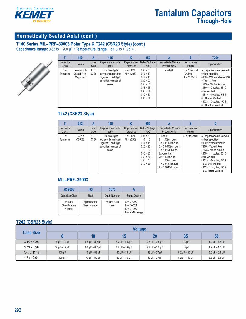
292
Tantalum CapacitorsThrough-Hole
Hermetically Sealed Axial (cont )T140 Series MIL–PRF–39003 Polar Type & T242 (CSR23 Style) (cont.)Capacitance Range: 0.82 to 1,200 μF • Temperature Range: −55°C to +125°C
lu u H s T1 0 S ries Ax al M L P F– 900
rder ng nfo mation – T140
T 140 A 105 K 050 A S 7200Capacitor
Class Series Case Size
Capa i ance Code (pF)
Capacitance Tolerance
Rated Voltage(VDC)
Failure Rate/Military Product Only
Term at on Finish Specifi cation
T = Tantalum
Hermetically Sealed Axial
Capacitor
A, B, C, D
First two digits represent signifi cant fi gures. Third digit
specifi es number of zeros.
K = ±10% M = ±20%
006 = 6 010 = 10 015 = 15 020 = 20 030 = 30 035 = 35 060 = 60 050 = 50 060 = 60
A = N/A S = Standard (Sn/Pb) T = 100% Tin
All capacitors are sleeved unless specifi ed. 0100 = Without sleeve 7200 = Tape & Reel7293 & 7443 = Ammo4250 = 10 cycles, 25 C after Weibull4251 = 10 cycles, -55 & 85 C after Weibull4252 = 10 cycles, -55 & 85 C before Weibull
T242 (CSR23 Style)
Ordering Information – T140
acass erie a
ize anc p )
cit T e a ce
d Vo(V C)
t Pr duc nly
n Fi s e ifi cat
t
me ic a i r
A B C D
two r en g
g d d g pecifi num e o
z
±1 % M 2
6
1 1 2 20 3 3 3 3
A = N/A S and ( P ) T
t a e l n
a & Re9 4
2 , t l
y C
4252 1 y l , 5 ul
Ordering Information
T 242 A 105 K 050 A S CCap citor
Class Series Case Size
Capacitance Code (pF)
Capacitance Tolerance
Rated Voltage(VDC)
Failure Rate/M litary Product Only
Termination Finish Specifi cation
T = Tantalum
T242 = CSR23
A, B, C, D
First two digits represent signifi cant fi gures. Third digit
specifi es number of zeros.
K = ±10% M = ±20%
006 = 6 0 0
015 = 15 020 = 20
0 0 035 = 35 060 = 60
5 5 060 = 60
Graded: B .1%/k hours C = 0 01%/k hours D = 0 001%/k hours G = 1 0%/k hours Expone tial: M = 1%/k hours
.1%/k hours R = 0 01%/k hours S = 0.001%/k hours
S = Standard All capacitors are sleeved unless specifi ed0100 = Without sleeve7200 = Tape & Reel 7293 & 7443= Ammo4250 = 1 cycles, 25 C after Weibull4251 = 10 cycles, -55 & 85 C after Weibull 4252 = 1 cycles, -55 & 85 C before Weibull
MIL–PRF–39003
T 140 A 1 5 K
a z
(pF)
ra
VDC
c
nis
T = antalum
l d Ax
Cap c tor
A, B, C D
First two d gits t s g
gures. T rd di u be f z os
K = ±10% M = ±20%
006 = 6 = 0
5
0 0 35 35
0 0
6 6
A N/A = Standard /Pb)
T 10 Tin
specifi ed
0 ithout s ee e T p eel
7293 & 7443 m5 1 y l
a r e bul425 1 cycles, &
5 C a te W25 1 y l 55 5 bef re eibu
Class
a Size
anc (pF
cit To erance
d Vo(V C)
at Product Only
n Finish
T = t l
CSR 3
B C, D
tw present s gnifi c
fi gures Third digit pecifi e number o
zeros
= ±10% M ±20%
= 010 1 015 = 15 0 0 0 030 30 035 = 35 060 60 050 50 060 = 60
d B = 0 1% C = 0 01% k hour D 0 001% k hour G 0%/k h urs E p nentia : M = 1%/k hou P 1% hour R = 0 01% k hour S 0 0 1% k hour
t nd un ess specifi ed0100 = Withou s7200 ape & Reel 7293 7443 Amm4250 = 10 cyc es 25 a ter eibull4 5 = 10 cy 85 C a te Weibu l 42 2 = 10 cycles - 85 C b fo e Weibul
Ord ring nforma
M39003 /03 3075 ACapacitor Class Slash Dash Number Surge Option
Military Specifi cation
Number
Specifi cation Sheet Number
Failure Rate Level
A = C-4250B = C-4251C = C-4252Blank - No surge
T242 (CSR23 Style)
Case SizeVoltage
6 10 15 20 35 503.18 x 6.35 10 μF – 12 μF 6.8 μF – 8.2 μF 4.7 μF – 5.6 μF 2.7 μF – 3.9 μF 1.8 μF 1.2 μF – 1.5 μF
3.43 x 7.26 10 μF – 12 μF 6.8 μF – 8.2 μF 4.7 μF – 5.6 μF 2.7 μF – 3.9 μF 1.8 μF 1.2 μF – 1.5 μF
4.45 x 11.13 100 μF 47 μF – 82 μF 33 μF – 39 μF 18 μF – 27 μF 8.2 μF – 10 μF 5.6 μF – 6.8 μF
4.7 x 12.04 100 μF 47 μF – 82 μF 33 μF – 39 μF 18 μF – 27 μF 8.2 μF – 10 μF 5.6 μF – 6.8 μF
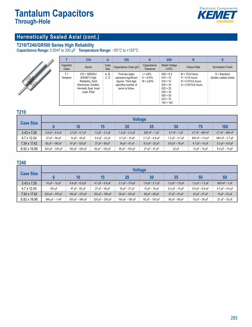
293
Tantalum CapacitorsThrough-Hole
Hermetically Sealed Axial (cont.)T210/T240/GR500 Series High ReliabilityCapacitance Range: 0.0047 to 330 μF Temperature Range: −55°C to +125°C
T u T u H e p to G T21 S i ig i bi t
Ordering I formation
T 210 A 105 K 050 R SCapacitor
Class Series Case Size Capacitance Code (pF) Capacitance
ToleranceRated Voltage
(VDC) Failure Rate Termination Finish
T = Tantalum
210 = GR500/J (KEMET) High
Reliability, Solid Electrolyte, Graded, Hermetic Seal, Axial
Lead, Polar
A, B, C, D
First two digits represent signifi cant fi gures. Third digit
specifi es number of zeros to follow.
J = ±5% K = ±10% M = ±20%
006 = 6.3010 = 10015 = 15020 = 20025 = 25 035 = 35050 = 50075 = 75100 = 100
M = 1%/k hours P = 0.1/k hours R = 0.01%/k hours S = 0.001%/k hours
S = Standard (Solder-coated nickel)
T210
Case SizeVoltage
6 10 15 20 35 50 75 1003.43 x 7.26 3.9 μF – 6.8 μF 2.7 μF – 4.7 μF 1.2 μF – 3.3 μF 1.2 μF – 2 2 μF 820 nF – 1 μF 4.7 nF – 1 μF 4.7 nF – 680 nF 4.7 nF – 560 nF
4.7 x 12.04 27 μF – 56 μF 12 μF – 39 μF 5.6 μF – 22 μF 4.7 μF – 15 μF 2.7 μF – 6.8 μF 1.2 μF – 4.7 μF 820 nF – 3 9 μF 680 nF – 2.7 μF
7.34 x 17.42 82 μF – 180 μF 47 μF – 120 μF 27 μF – 68 μF 18 μF – 47 μF 8.2 μF – 22 μF 5.6 μF – 18 μF 4.7 μF – 10 μF 3.3 μF – 6.8 μF
8.92 x 19.96 220 μF – 330 μF 150 μF – 220 μF 82 μF – 150 μF 56 μF – 100 μF 27 μF – 47 μF 22 μF 12 μF – 15 μF 8.2 μF – 10 μF T240
Case SizeVoltage
6 10 15 20 30 35 50 603.43 x 7.26 10 μF – 12 μF 6.8 μF – 8.2 μF 4.7 μF – 6.8 μF 2.7 μF – 3 9 μF 1.8 μF – 2.7 μF 1.2 μF – 1.8 μF 1.2 μF – 1 5 μF 820 nF – 1 μF
4.7 x 12.04 100 μF 47 μF – 82 μF 27 μF – 39 μF 18 μF – 27 μF 12 μF – 18 μF 8.2 μF – 10 μF 5.6 μF – 6.8 μF 4.7 μF – 5.6 μF
7.34 x 17.42 220 μF – 470 μF 150 μF – 270 μF 150 μF – 180 μF 56 μF – 120 μF 56 μF – 68 μF 27 μF – 47 μF 22 μF – 27 μF 12 μF – 22 μF
8.92 x 19.96 680 μF – 1 mF 330 μF – 560 μF 220 μF – 330 μF 150 μF – 180 μF 82 μF – 100 μF 56 μF – 68 μF 33 μF – 39 μF 27 μF – 33 μF
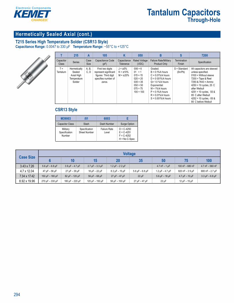
294
Tantalum CapacitorsThrough-Hole
Hermetically Sealed Axial (cont.)T215 Series High Temperature Solder (CSR13 Style)Capacitance Range: 0.0047 to 330 μF Temperature Range: −55°C to +125°C
T u T u H e to T S i i l h T t e
Ordering I formation
T 215 A 105 K 050 B S 7200Capacitor
Class Series Case Size
Capacitance Code (pF)
Capacitance Tolerance
Rated Voltage(VDC)
Failure Rate/Military Product Only
Termination Finish Specifi cation
T = Tantalum
Hermetically Sealed
Axial High Temperature
Solder
A, B, C, D
First two digits represent signifi cant fi gures Third digit
specifi es number of zeros.
J = ±5% K = ±10% M = ±20%
006 = 6 01 = 1 015 = 15020 = 20035 = 35 050 = 50 075 = 75 100 = 100
Graded:B = 0.1%/k hours C = 0.01%/k hours D = 0 001%/k hours G= 1.0 %/k hours Exponential: M = 1%/k hours P = 0.1%/k hours R = 0.01%/k hours S = 0.001%/k hours
S = Standard (Sn/Pb)
All capacitors are sleeved unless specifi ed.0100 = Without sleeve7200 = Tape & Reel7293 & 7443 = Ammo4250 = 10 cycles, 25 C after Weibull4251 = 10 cycles, 55 & 85 C after Weibull4252 = 10 cycles, -55 & 85 C before Weibull
CSR13 Style
T2 5 S ie Ax al H h Temperat e
Ordering Inform tion
C ass
Size
(pF)
Tolerance
(VDC)
Product Only
Finish
nta
Sealed xial Hig
Tempe atur S lder
C D
p esent s gn fi c
fi gures Third dig t specifi e number o
zeros
K ± 0 M 2 %
0 0 = 1 015 1502 = 2035 35 050 50 0 5 = 75 00 = 10
B = 0 1 C 01%/k hou D = 0 001% k hour G= 1 0 % k hours E on nti l: M = 1% k ho P = 1% k hour R 01%/k hou S = 0 001% k hour
Sn/Pb)
un ess spec fi ed0100 = Without 7200 Tape & Reel7293 7443 = mm4250 = 10 c c es 25 a t r ei ul425 10 cy 85 C fter Weibull42 2 = 10 ycles 85 C efore Weibull
Order ng Info
M39003 /01 6003 ECapacitor Class Slash Dash Number Surge Option
Military Specifi cation
Number
Specifi cation Sheet Number
Failure Rate Level
D = C-4250E = C-4251F = C-4252H = No C-Spec
Case SizeVoltage
6 10 15 20 35 50 75 1003.43 x 7.26 5.6 μF – 6.8 μF 3.9 μF – 4.7 μF 2.7 μF – 3.3 μF 1.2 μF – 2 2 μF 4.7 nF – 1 μF 100 nF – 680 nF 4.7 nF – 560 nF
4.7 x 12.04 47 μF – 56 μF 27 μF – 39 μF 18 μF – 22 μF 8 2 μF – 15 μF 5.6 μF – 6.8 μF 1.2 μF – 4.7 μF 820 nF – 3 9 μF 680 nF – 2.7 μF
7.34 x 17.42 150 μF – 180 μF 82 μF – 120 μF 56 μF – 68 μF 27 μF – 47 μF 22 μF 5.6 μF – 18 μF 4.7 μF – 10 μF 3.3 μF – 6.8 μF
8.92 x 19.96 270 μF – 330 μF 180 μF – 220 μF 120 μF – 150 μF 56 μF – 100 μF 27 μF – 47 μF 22 μF 12 μF – 15 μF

295
Tantalum CapacitorsThrough-Hole
Hermetically Sealed Axial (cont.)T216 Series MIL–PRF–39003 (CSS13 Style) and T256 (CSS33 Style)Capacitance Range: CSS13: 0.12 to 330 μF, CSS33: 1.2 to 1,000 μF • Temperature Range: −55°C to +125°C
T u T u H e p to T S i i l – RF 3 3
Ordering In or a ion – T2 6 T256
T 216 A 106 K 050 C SCapacitor
Class Series Case Size
Capac tance Code (pF)
Capacitance Tolerance
Rated Voltage(VDC) Failure Rate Terminat on
Finish C-Spec
T = Tantalum
216 (MIL–C–39003/10,
CSS13)
256 (MIL–C–39003/10,
CSS33)
A, B, C, D
First two digits represent signifi cant
fi gures. Third digit specifi es number
of zeros.
K = ±10% 006 = 6 010 = 10 015 = 15 020 = 20 035 = 35 050 = 50 075 = 75
Graded: B = 0.1%/k hours C = 0.01%/k hours
S = Standard (Solder-coated
nickel)
Blank = Sleeved0100 = Unsleeved7200 = Tape & Reel7200 = Tape & Reel7293 & 7443 = Ammo
CSS13 Style
T 216 106 K 50 C
a er e iz
d (p
ra
VDC e
ni
T = ntalu
21
SS
256
SS3
A B C D
irst two digit represent signi ant
es. Third cifi es num
f eros
K = ±10% 006 = 6 = 10
5 020 = 0 035 = 35
5 5 075 = 75
aded: 0 1
Standard der-co nickel)
= Sl v
72 0 Ta e & 00 = Tape & Re
293 & 7443 = Am o
M L product
M39003 /10 2049 SCapacitor Class Slash Dash Number Sleeve
Military Specifi cation Number
Specifi cation Sheet Number
Failure Rate Level S = SleevedU = Unsleeved use C - 0100
CSS33 Style
ta
216 106 K
C as S ries Size
Cod ( F
To eranc
(V ) Fa lure R
a
–390
( 3
S 3)
,
res
signifi cant re T ird d
of z r s
= 10
015 = 15 = 20
5 5 75 5
/k
r-
nickel)
= Tape
mm
Information SS13
M39003
Number
umbe
ved use
M L product
M39003 /10 2549 SCapacitor Class Slash Dash Number Sleeve
Military Specifi cation Number
Specifi cation Sheet Number
Failure Rate Level S = SleevedU = Unsleeved use C - 0100
T216 (CSS13 Style)
Case SizeVoltage
6 10 15 20 35 50 753.18 x 6.35 5.6 μF – 6.8 μF 3 9 μF – 4.7 μF 2.7 μF – 3.3 μF 1.2 μF – 2.2 μF 120 nF – 820 nF 150 nF – 680 nF
3.43 x 7.26 5.6 μF – 6.8 μF 3 9 μF – 4.7 μF 2.7 μF – 3.3 μF 1.2 μF – 2.2 μF 120 nF – 820 nF 150 nF – 680 nF
4.45 x 11.13 47 μF – 56 μF 27 μF – 39 μF 18 μF – 22 μF 8.2 μF – 15 μF 5.6 μF – 6.8 μF 1 μF – 4.7 μF 820 nF – 3.9 μF
4.7 x 12.04 47 μF – 56 μF 27 μF – 39 μF 18 μF – 22 μF 8.2 μF – 15 μF 5.6 μF – 6.8 μF 1 μF – 4.7 μF 820 nF – 3.9 μF
T256 (CSS33 Style)
Case SizeVoltage
6 10 15 20 35 503.18 x 6.35 10 μF – 12 μF 6.8 μF – 8.2 μF 4.7 μF – 5.6 μF 2.7 μF – 3.9 μF 1.8 μF 1.2 μF – 1.5 μF
3.43 x 7.26 10 μF – 12 μF 6.8 μF – 8.2 μF 4.7 μF – 5.6 μF 2.7 μF – 3.9 μF 1.8 μF 1.2 μF – 1.5 μF
4.45 x 11.13 100 μF 47 μF – 82 μF 33 μF – 39 μF 18 μF – 27 μF 8.2 μF – 10 μF 5.6 μF – 6.8 μF
4.7 x 12.04 100 μF 47 μF – 82 μF 33 μF – 39 μF 18 μF – 27 μF 8.2 μF – 10 μF 5.6 μF – 6.8 μF

296
Tantalum CapacitorsThrough-Hole
Hermetically Sealed Axial (cont.) T222 Series MIL–PRF–39003 Polar Miniature (CSR09 Style)Capacitance Range: 0.047 to 18 μF • Temperature Range: −55°C to +125°C
T u T u H e p to T 2 S i l –P F 3
O de in Information
T 222 A 225 K 010 B S CCapacitor
Class Series Case Size
Capacitanc Code (pF)
Capacitance Tolerance
Rated Voltage(VDC)
Failure Rate/Military Produ t Only
Termination Finish Specifi cation
T = Tantalum
T222 (CSR09)
A, B First two digits represent signifi cant fi gures. Third digit
specifi es number of zeros.
J = ±5% K = ±10%
006 = 6 010 = 10 015 = 15 020 = 20 035 = 35 050 = 50 075 = 75
Graded: B = 0.1%/k hours C = 0.01%/k hours D = 0.001%/k hours G = 1.0%/k hoursExponential: M = 1%/k hours P = 0.1%/k hours R = 0.01%/k hours S = 0.001%/k hours
S = StandardPositive: Alloy
52 (solder-coated)
Negative: Solder-
coated nickel
All capacitors are sleeved unless specifi ed.7200 = Tape & Reel 7293 & 7443 = Ammo
CSR09 Style
rd i g r t
T 2
a erie iz
ode (
ra
VDC
uc
ni i c
T = antalu
222 A B First two digit e ent signi
gu es. T ird dig specifi es number of
z ros.
J = ±5% = ±10%
006 = 6 0 = 10
0 5 = 020 2 035 3 050 50 0 5 5
Graded 1%/k hour
C = 0 0 D 001%/k ho G .0%/k hoursEx onential: M 1% k hou s P = 0.1%/k R 0 01%/k ho S 0 001%/k hou
S = Standaritive: A (solde
coated)Negative Solder-
oated nick
pac tors are s
72 0 Tape & Reel 7293 & 7443 = A
M L product
M39003 /02 2061 DCapacitor Class Slash Dash Number Surge Option
Military Specifi cation
Number
Specifi cation Sheet Number
Failure Rate Level
D = C-4250E = C-4251F = C-4252H = No C-Spec
Case SizeVoltage
6 10 15 20 35 50 752.29 x 6.35 2.7 μF 1.8 μF – 2.2 μF 1 μF – 1.5 μF 560 nF – 1 μF 330 nF – 470 nF 220 nF – 270 nF 47 nF – 180 nF
3.51 x 9.91 18 μF 10 μF – 15 μF 8.2 μF 3.3 μF – 6.8 μF 2.2 μF – 2.7 μF 1.5 μF – 1.8 μF 220 nF – 1.2 μF
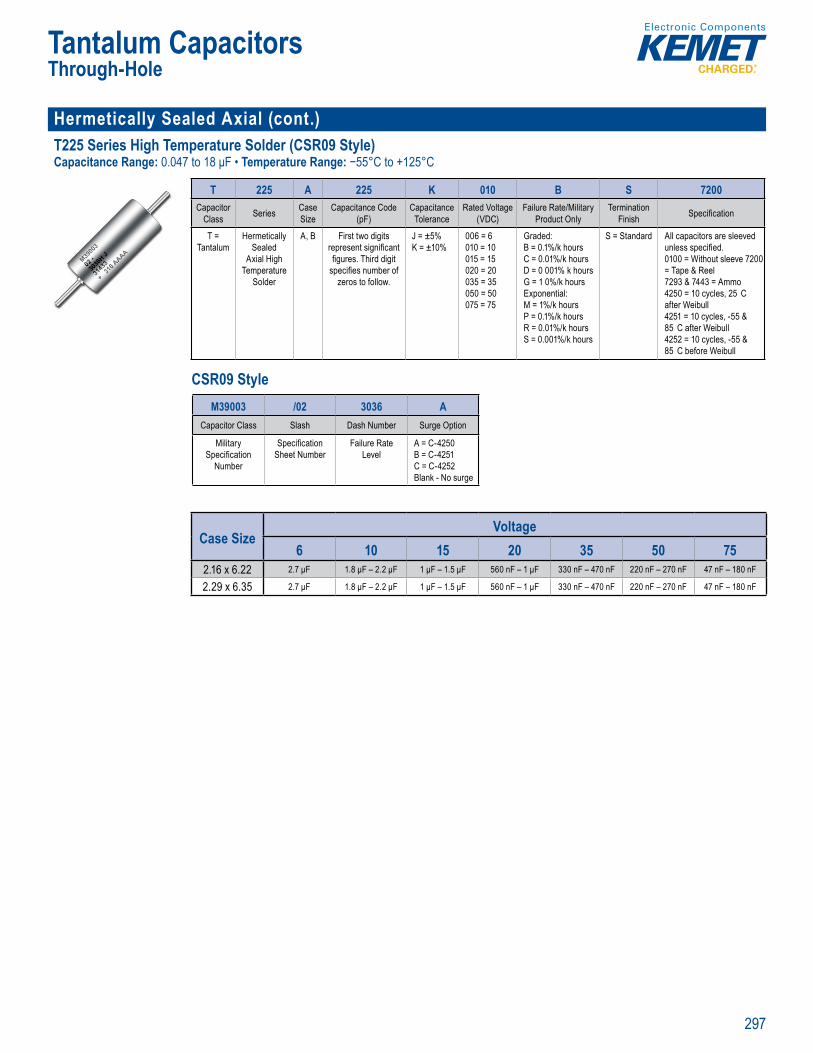
297
Tantalum CapacitorsThrough-Hole
Hermetically Sealed Axial (cont.) T225 Series High Temperature Solder (CSR09 Style)Capacitance Range: 0.047 to 18 μF • Temperature Range: −55°C to +125°C
T u a x l T225 S ri s H gh Temperature Solde
O de in Information
T 225 A 225 K 010 B S 7200Capacitor
Class Series Case Size
Capacitance Code (pF)
Capacitance Tolerance
Rated Voltage(VDC)
Failure Rate/Military Product Only
Termination Finish Specifi cation
T = Tantalum
Hermetically Sealed
Axial High Temperature
Solder
A, B First two digits represent signifi cant fi gures. Third digit
specifi es number of zeros to follow.
J = ±5% K = ±10%
006 = 6 010 = 10015 = 15 020 = 20 035 = 35 050 = 50 075 = 75
Graded:B = 0.1%/k hours C = 0.01%/k hours D = 0 001% k hoursG = 1 0%/k hoursExponential:M = 1%/k hours P = 0.1%/k hours R = 0.01%/k hours S = 0.001%/k hours
S = Standard All capacitors are sleeved unless specifi ed. 0100 = Without sleeve 7200 = Tape & Reel7293 & 7443 = Ammo4250 = 10 cycles, 25 C after Weibull4251 = 10 cycles, -55 & 85 C after Weibull4252 = 10 cycles, -55 & 85 C before Weibull
CSR09 Style
derin In orm tion
a erie a tanc ci d Vo at
min cifi
T = rm tic
x l Hi h mper t So er
A, B two
ure T ird di sp cifi es number f
zer s f l w
J = ±5%
6 = 6
5 2 2 3 3 5 5 75 75
aded
C = 0 01 001% k ho
G %/k oursE n t l:M 1% k ho rs P = 0 1%/k h
0 1 /k ho 001% k hou
Stand acito ar l
01 0 = itho t s e ve 72 = Tap & e l72 3 44 = mmo
50 = 10 cyc t eibul
425 1 cycles 85 C ter W4252 1 cycles, 5 &
5 C befo W ib
Ordering Info
M39003 /02 3036 ACapacitor Class Slash Dash Number Surge Option
Military Specifi cation
Number
Specifi cation Sheet Number
Failure Rate Level
A = C-4250B = C-4251C = C-4252Blank - No surge
Case SizeVoltage
6 10 15 20 35 50 752.16 x 6.22 2.7 μF 1.8 μF – 2.2 μF 1 μF – 1.5 μF 560 nF – 1 μF 330 nF – 470 nF 220 nF – 270 nF 47 nF – 180 nF
2.29 x 6.35 2.7 μF 1.8 μF – 2.2 μF 1 μF – 1.5 μF 560 nF – 1 μF 330 nF – 470 nF 220 nF – 270 nF 47 nF – 180 nF
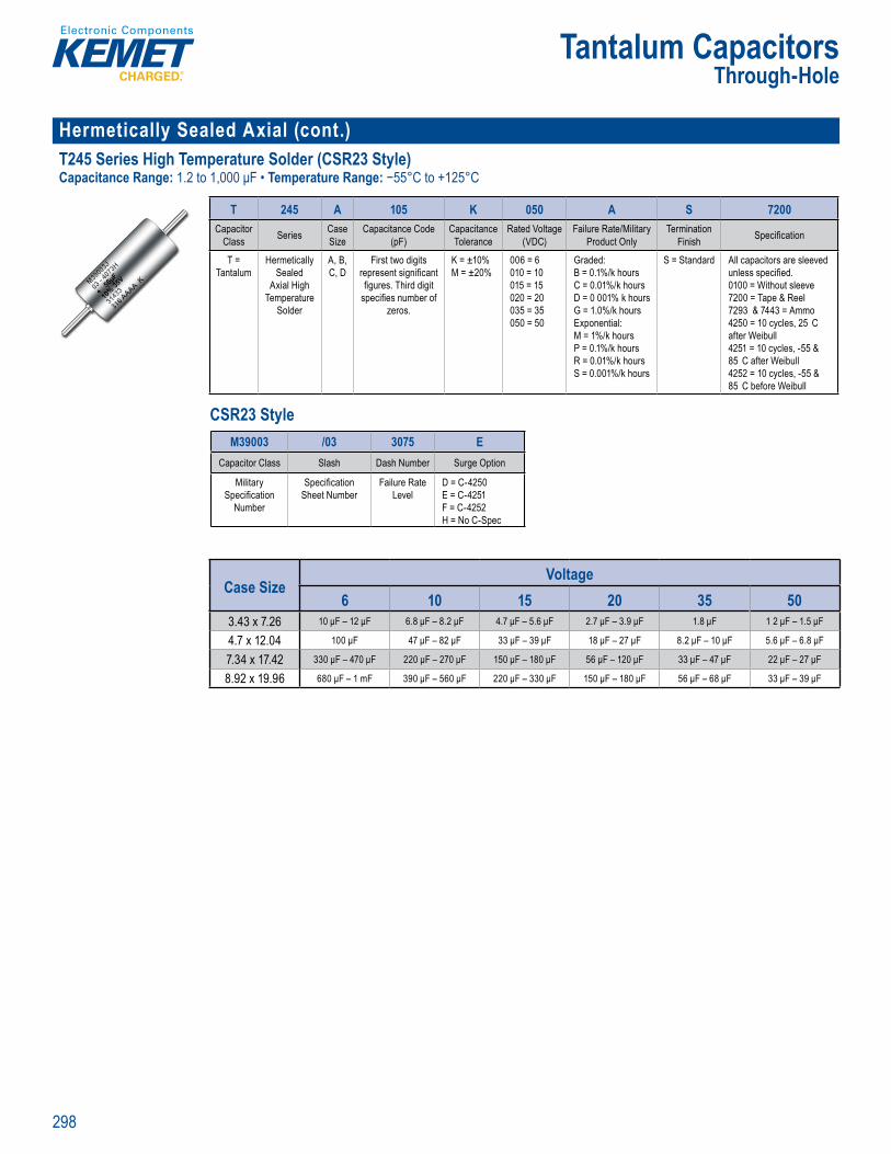
298
Tantalum CapacitorsThrough-Hole
Hermetically Sealed Axial (cont.) T245 Series High Temperature Solder (CSR23 Style)Capacitance Range: 1.2 to 1,000 μF • Temperature Range: −55°C to +125°C
T u u H e to T 45 S ri s Ax l H h T m er tu e
rde n Informat on
T 245 A 105 K 050 A S 7200Capacitor
Class Series Case Size
Capacitance Code (pF)
Capacitance Tolerance
Rated Voltage(VDC)
Failure Rate/Military Product Only
Termination Finish Specifi cation
T = Tantalum
Hermetically Sealed
Axial High Temperature
Solder
A, B, C, D
First two digits represent signifi cant fi gures. Third digit
specifi es number of zeros.
K = ±10% M = ±20%
006 = 6 010 = 10 015 = 15 020 = 20 035 = 35050 = 50
Graded:B = 0.1%/k hours C = 0.01%/k hours D = 0 001% k hours G = 1.0%/k hoursExponential:M = 1%/k hours P = 0.1%/k hours R = 0.01%/k hours S = 0.001%/k hours
S = Standard All capacitors are sleeved unless specifi ed.0100 = Without sleeve 7200 = Tape & Reel7293 & 7443 = Ammo4250 = 10 cycles, 25 C after Weibull4251 = 10 cycles, -55 & 85 C after Weibull4252 = 10 cycles, -55 & 85 C before Weibull
CSR23 Style
derin In orm tion
a Serie a tanc ci d Vo a
min e ifi ca
T = rmetic
Ax al High mper t So er
A, B
two
u es Third di specifi es number of
z r s
= ±10%
6 = 6
0 5 = 1 02 = 2
3 3050 50
aded
C = 0 0 D 001% k ho G %/k oursEx one tial:M = 1% k hours P = 0 1%/k h R = 0 01%/k ho
= 0 001% k hou
Stand acito s are sl
0100 = Without s eeve 7200 = Tape & R72 3 744 = Amm4250 = 10 cyc es 2 a ter W ibull425 1 cycles 85 C after W4252 = 1 c cles - 5 & 85 C before Weib
Ordering Inf
M39003 /03 3075 ECapacitor Class Slash Dash Number Surge Option
Military Specifi cation
Number
Specifi cation Sheet Number
Failure Rate Level
D = C-4250E = C-4251F = C-4252H = No C-Spec
Case SizeVoltage
6 10 15 20 35 503.43 x 7.26 10 μF – 12 μF 6.8 μF – 8.2 μF 4.7 μF – 5.6 μF 2.7 μF – 3.9 μF 1.8 μF 1 2 μF – 1.5 μF
4.7 x 12.04 100 μF 47 μF – 82 μF 33 μF – 39 μF 18 μF – 27 μF 8.2 μF – 10 μF 5.6 μF – 6.8 μF
7.34 x 17.42 330 μF – 470 μF 220 μF – 270 μF 150 μF – 180 μF 56 μF – 120 μF 33 μF – 47 μF 22 μF – 27 μF
8.92 x 19.96 680 μF – 1 mF 390 μF – 560 μF 220 μF – 330 μF 150 μF – 180 μF 56 μF – 68 μF 33 μF – 39 μF
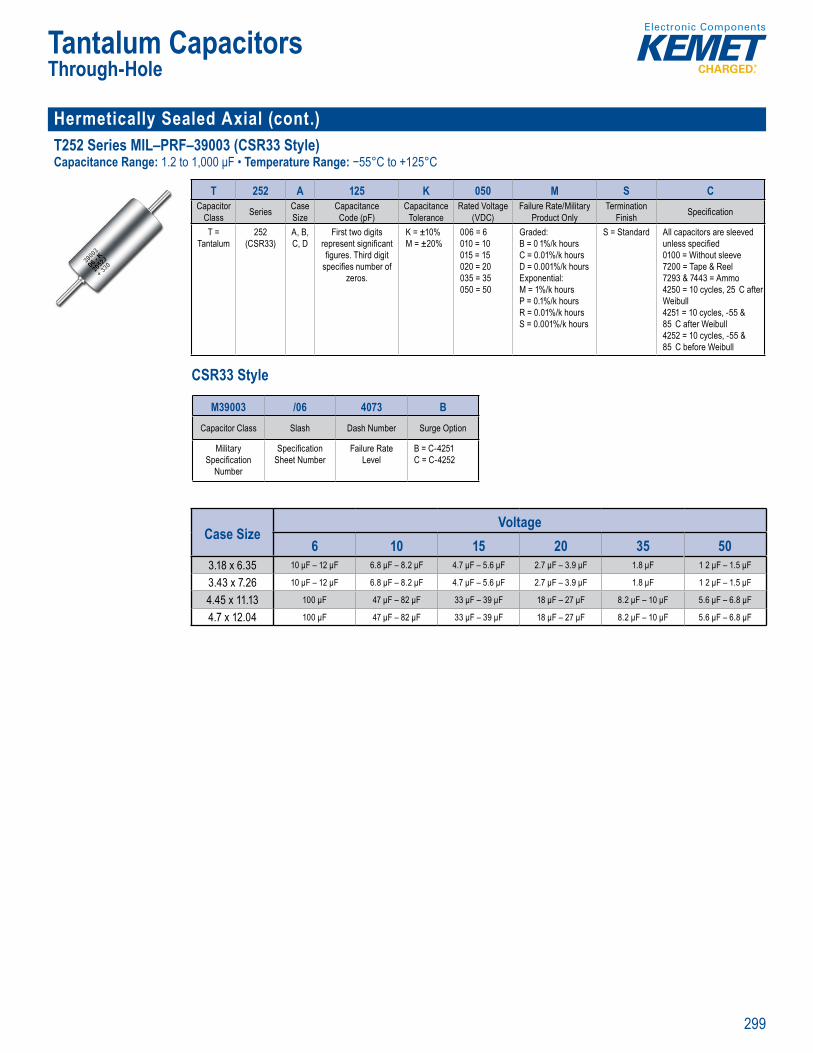
299
Tantalum CapacitorsThrough-Hole
Hermetically Sealed Axial (cont.)T252 Series MIL–PRF–39003 (CSR33 Style)Capacitance Range: 1.2 to 1,000 μF • Temperature Range: −55°C to +125°C
T n a u T rou H le Cap c to
rde n Info mat on
T 252 A 125 K 050 M S CCapacitor
Class Series Case Size
Capacitance Code (pF)
Capacitance Tolerance
Rated Voltage(VDC)
Failure Rate/Military Product Only
Termination Finish Specifi cation
T = Tantalum
252 (CSR33)
A, B, C, D
First two digits represent signifi cant fi gures. Third digit
specifi es number of zeros.
K = ±10% M = ±20%
006 = 6 010 = 10 015 = 15 020 = 20 035 = 35 050 = 50
Graded: B = 0 1%/k hours C = 0.01%/k hours D = 0.001%/k hours Exponential: M = 1%/k hours P = 0.1%/k hours R = 0.01%/k hours S = 0.001%/k hours
S = Standard All capacitors are sleeved unless specifi ed0100 = Without sleeve7200 = Tape & Reel 7293 & 7443 = Ammo4250 = 10 cycles, 25 C after Weibull4251 = 10 cycles, -55 & 85 C after Weibull 4252 = 10 cycles, -55 & 85 C before Weibull
CSR33 Style
O d f r
T 252 A 125 K
la iz
de (
r
(VDC
uc
ni
T antalu
CSR33
A, B C,
irst two d gi e nt igni
g ifi mb
zeros
K ±1 % M = ±2
= 6 = 10
3 3 5 5
G aded: k ur
E n ti l / = 0 1% k
S /k
S Standar specifi ed
7 T l 7293 & 7443 = A2 1 l , 25
W25 = 1 c s 55 5 t W bu l 52 =
85 C f re Weib l
M L product
M39003 /06 4073 BCapacitor Class Slash Dash Number Surge Option
Military Specifi cation
Number
Specifi cation Sheet Number
Failure Rate Level
B = C-4251C = C-4252
Case SizeVoltage
6 10 15 20 35 503.18 x 6.35 10 μF – 12 μF 6.8 μF – 8.2 μF 4.7 μF – 5.6 μF 2.7 μF – 3.9 μF 1.8 μF 1 2 μF – 1.5 μF
3.43 x 7.26 10 μF – 12 μF 6.8 μF – 8.2 μF 4.7 μF – 5.6 μF 2.7 μF – 3.9 μF 1.8 μF 1 2 μF – 1.5 μF
4.45 x 11.13 100 μF 47 μF – 82 μF 33 μF – 39 μF 18 μF – 27 μF 8.2 μF – 10 μF 5.6 μF – 6.8 μF
4.7 x 12.04 100 μF 47 μF – 82 μF 33 μF – 39 μF 18 μF – 27 μF 8.2 μF – 10 μF 5.6 μF – 6.8 μF
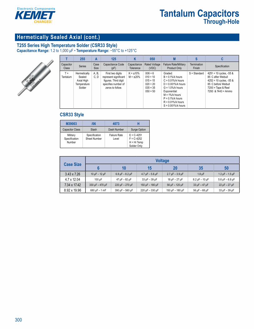
300
Tantalum CapacitorsThrough-Hole
Hermetically Sealed Axial (cont.) T255 Series High Temperature Solder (CSR33 Style)Capacitance Range: 1.2 to 1,000 μF • Temperature Range: −55°C to +125°C
T255 S ies Ax al H h Temperatu e
rde n In or at
T 255 A 125 K 050 M S CCapacitor
Class Series Case Size
Capacitance Code (pF)
Capacitance Tolerance
Rated Voltage(VDC)
Failure Rate/Military Product Only
Termination Finish Specifi cation
T = Tantalum
Hermetically Sealed
Axial High Temperature
Solder
A, B, C, D
First two digits represent signifi cant fi gures. Third digit
specifi es number of zeros to follow.
K = ±10% M = ±20%
006 = 6 010 = 10 015 = 15 020 = 20035 = 35 050 = 50
Graded: B = 0.1%/k hours C = 0.01%/k hours D = 0.001%/k hoursG = 1.0%/k hoursExponential: M = 1%/k hours P = 0.1%/k hours R = 0.01%/k hours S = 0.001%/k hours
S = Standard 4251 = 10 cycles, -55 & 85 C after Weibull4252 = 10 cycles, -55 & 85 C before Weibull 7200 = Tape & Reel 7293 & 7443 = Ammo
CSR33 Style
derin In orm tion
a a tanc ( )
ci d VoV )
at d c nly
min n
T = nt
i
x pe atu
e
A, B ,
two pr n gn . d d g p ifi nu be f
e o l
= ±10% 2
6 = 6
2 2
aded: B 1 C D 1% k
E e ti l M k
k 1% k
Stand 1 l 5 C t e
2 2 cy l , C bef W i ull
2 T p & el
Ordering Info
M39003 /06 4073 HCapacitor Class Slash Dash Number Surge Option
Military Specifi cation
Number
Specifi cation Sheet Number
Failure Rate Level
E = C-4251F = C-4252H = Hi Temp Solder Only
Case SizeVoltage
6 10 15 20 35 503.43 x 7.26 10 μF – 12 μF 6.8 μF – 8.2 μF 4.7 μF – 5.6 μF 2.7 μF – 3.9 μF 1.8 μF 1 2 μF – 1.5 μF
4.7 x 12.04 100 μF 47 μF – 82 μF 33 μF – 39 μF 18 μF – 27 μF 8.2 μF – 10 μF 5.6 μF – 6.8 μF
7.34 x 17.42 330 μF – 470 μF 220 μF – 270 μF 150 μF – 180 μF 56 μF – 120 μF 33 μF – 47 μF 22 μF – 27 μF
8.92 x 19.96 680 μF – 1 mF 390 μF – 560 μF 220 μF – 330 μF 150 μF – 180 μF 56 μF – 68 μF 33 μF – 39 μF
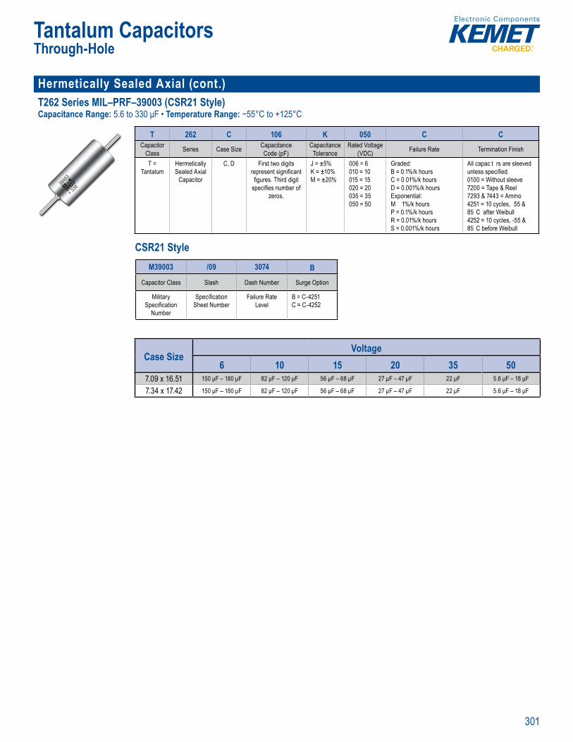
301
Tantalum CapacitorsThrough-Hole
Hermetically Sealed Axial (cont.)T262 Series MIL–PRF–39003 (CSR21 Style)Capacitance Range: 5.6 to 330 μF • Temperature Range: −55°C to +125°C
T n a u T rou H le Cap c to –
Order g nfo mati n
T 262 C 106 K 050 C CCapacitor
Class Series Case Size Capacitance Code (pF)
Capacitance Tolerance
Rated Voltage(VDC) Failure Rate Termination Finish
T = Tantalum
Hermetically Sealed Axial
Capacitor
C, D First two digits represent signifi cant fi gures. Third digit
specifi es number of zeros.
J = ±5% K = ±10% M = ±20%
006 = 6 010 = 10 015 = 15 020 = 20 035 = 35 050 = 50
Graded: B = 0.1%/k hours C = 0 01%/k hours D = 0.001%/k hours Exponential: M 1%/k hours P = 0.1%/k hours R = 0.01%/k hours S = 0.001%/k hours
All capac t rs are sleeved unless specifi ed. 0100 = Without sleeve7200 = Tape & Reel7293 & 7443 = Ammo4251 = 10 cycles, 55 & 85 C after Weibull4252 = 10 cycles, -55 & 85 C before Weibull
CSR21 Style
Ord ring Inf rmatio
T Tantalum
ti aled
resent signifi
res Thir pecifi es number
ze os
K = ±10% M = ±20%
010 = 10
5 = 15 020 = 2 035 35 050 = 5
/k hours
D = 0 00 Ex onential: M 1%/k h urs P = 0 1%/k hours R = 0.01%/k S = 0 00 %/k h
ss speci ed.
7200 = Tape & Reel7293 & 7443 = A425 = 10 cycles -55 85 C fter W ibull4252 = 10 cyc es, -55 85 C ef re Weibu l
M L product
M39003 /09 3074 BCapacitor Class Slash Dash Number Surge Option
Military Specifi cation
Number
Specifi cation Sheet Number
Failure Rate Level
B = C-4251C = C-4252
Case SizeVoltage
6 10 15 20 35 507.09 x 16.51 150 μF – 180 μF 82 μF – 120 μF 56 μF – 68 μF 27 μF – 47 μF 22 μF 5.6 μF – 18 μF
7.34 x 17.42 150 μF – 180 μF 82 μF – 120 μF 56 μF – 68 μF 27 μF – 47 μF 22 μF 5.6 μF – 18 μF
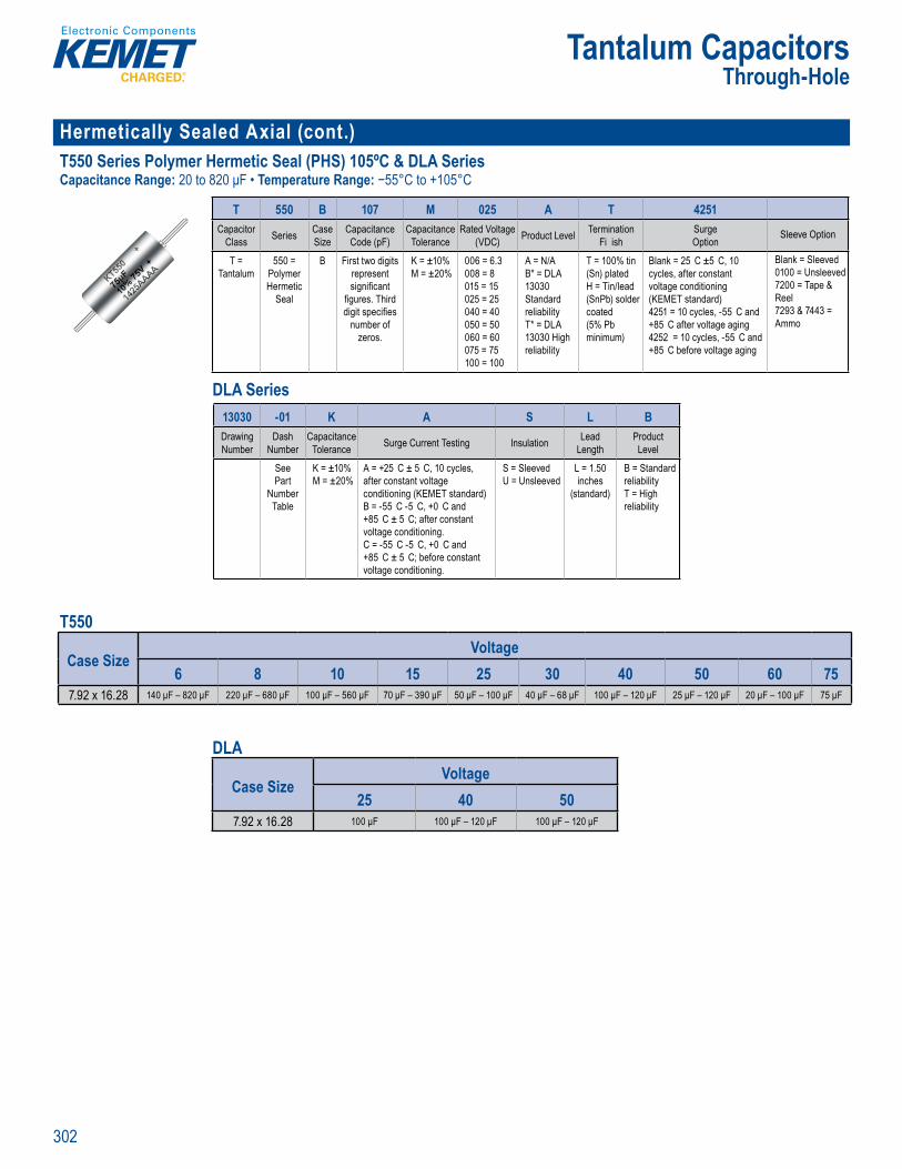
302
Tantalum CapacitorsThrough-Hole
Hermetically Sealed Axial (cont.) T550 Series Polymer Hermetic Seal (PHS) 105ºC & DLA SeriesCapacitance Range: 20 to 820 μF • Temperature Range: −55°C to +105°C
T 50 A al Po ymer e metic Seal (P
Or e g Inf m on
T 550 B 107 M 025 A T 4251Capacitor
Class Series Case Size
Capacitance Code (pF)
Capacitance Tolerance
Rated Voltage(VDC) Product Level Termination
Fi ishSurge Option
Sleeve Option
T = Tantalum
550 = Polymer Hermetic
Seal
B First two digits represent signifi cant
fi gures. Third digit specifi es
number of zeros.
K = ±10%M = ±20%
006 = 6.3008 = 8015 = 15025 = 25 040 = 40050 = 50060 = 60075 = 75100 = 100
A = N/AB* = DLA 13030 Standard reliabilityT* = DLA 13030 High reliability
T = 100% tin (Sn) platedH = Tin/lead (SnPb) solder coated (5% Pb minimum)
Blank = 25 C ±5 C, 10 cycles, after constant voltage conditioning (KEMET standard)4251 = 10 cycles, -55 C and +85 C after voltage aging4252 = 10 cycles, -55 C and +85 C before voltage aging
Blank = Sleeved0100 = Unsleeved7200 = Tape & Reel 7293 & 7443 = Ammo
DLA Series
Ord ing Inf rma io
T 550 B 107 M 0C p C
C p i
C
Tantalum
yme
e l
represent
gnifi cant fi gures Third
g t spe ifi number o
zer s.
M = ±20%
008 = 8
5 = 152 25
5 5
0 075 75
10 1
B = DL
St nda reli b l tyT = 13 30 Hi re iability
Sn) plated Tin/le
(Sn b) solde coa ed (5 Pb minimu )
r cons nditioni
(KEMET s anda d)25 0 c cles, 55
5 C te vo tage 4252 = 1 cycles, + C b o e vo age a ing
10 nslee
Reel 293 7 43
A o
Ord ri g
13030 -01 K A S L BDrawing Number
Dash Number
Capacitance Tolerance Surge Current Testing Insulation Lead
LengthProduct Level
See Part
Number Table
K = ±10% M = ±20%
A = +25 C ± 5 C, 10 cycles, after constant voltage conditioning (KEMET standard)B = -55 C -5 C, +0 C and +85 C ± 5 C; after constant voltage conditioning.C = -55 C -5 C, +0 C and +85 C ± 5 C; before constant voltage conditioning.
S = SleevedU = Unsleeved
L = 1.50 inches
(standard)
B = Standard reliability T = High reliability
T550
Case SizeVoltage
6 8 10 15 25 30 40 50 60 757.92 x 16.28 140 μF – 820 μF 220 μF – 680 μF 100 μF – 560 μF 70 μF – 390 μF 50 μF – 100 μF 40 μF – 68 μF 100 μF – 120 μF 25 μF – 120 μF 20 μF – 100 μF 75 μF
DLA
Case SizeVoltage
25 40 507.92 x 16.28 100 μF 100 μF – 120 μF 100 μF – 120 μF

303
Tantalum CapacitorsThrough-Hole
Hermetically Sealed Axial (cont.)T551 Series Polymer Hermetic Seal (PHS) 125ºCCapacitance Range: 20 to 820 μF • Temperature Range: −55°C to +125°C
T u u H e to T551 A a P lymer erm ti S l P
Orderi g Info mation
T 551 B 107 M 025 A T 4251Capacitor
Class Series Case Size
Capacitance Code (pF)
Capacitance Tolerance
Rated Voltage(VDC) Product Level Termination Finish Surge Option Sleeve Option
T = Tantalum
551 = Polymer Hermetic
Seal
B First two digits represent
signifi cant fi gures. Third digit specifi es
number of zeros.
K = ±10%M = ±20%
006 = 6.3 V008 = 8 V015 = 15 V 025 = 25 V 040 = 40 V050 = 50 V060 = 60 V
A = N/A T = 100% tin (Sn) platedH = Tin/lead (SnPb) solder coated (5% Pb minimum)
4251 = Surge current,
10 cycles, -55 C and
+85 C
Blank = Sleeved0100 = Unsleeved7200 = Tape & Reel 7293 & 7443 = Ammo
Case SizeVoltage
6 8 10 15 25 30 40 50 607.92 x 16.28 140 μF – 820 μF 220 μF – 680 μF 100 μF – 560 μF 70 μF – 390 μF 50 μF – 100 μF 40 μF – 68 μF 100 μF – 120 μF 25 μF – 120 μF 20 μF – 100 μF
Radial Dipped T350, T351, T352, T353, T354, T355 and T356 Series UltraDip II PolarCapacitance Range: 0.1 to 680 μF • Temperature Range: −55°C to +125°C
U traDip II Pola
Or er g Informati n
T 35X A 105 M 035 A SCapacitor
Class Series Case Size Capacitance Code (pF) Capacitance
ToleranceRated Voltage
(VDC) Failure Rate Termination Finish Specifi cation
T = Tantalum
350351352353354355356
A, B, C, D, E, F, G, H, J, K, L, M
First two digits represent signifi cant fi gures. Third digit
specifi es number of zeros to follow.
M = ±20%K = ±10%J = ±5% (Available on special order)
003 = 3006 = 6010 = 10016 = 16020 = 20025 = 25035 = 35050 = 50
Not Applicable S = Standard 7301 & 7303 = Tape & Reel7305 & 7317 = Ammo
T350
Case SizeVoltage
3 6.3 10 16 20 25 35 504.5 x 7.1 4.7 μF – 10 μF 3.3 μF – 6.8 μF 2.2 μF – 4.7 μF 1.5 μF – 3 3 μF 1 μF – 2.2 μF 1 μF – 1.8 μF 100 nF – 1 μF 100 nF – 330 nF
4.5 x 7.6 12 μF – 15 μF 8.2 μF – 10 μF 5.6 μF – 6.8 μF 3.9 μF – 4.7 μF 2.7 μF – 3.3 μF 2.2 μF – 3.3 μF 1.2 μF – 1.5 μF 390 nF – 1 μF
5 x 8.4 18 μF – 22 μF 12 μF – 15 μF 8.2 μF – 10 μF 5.6 μF – 6.8 μF 3.9 μF – 4.7 μF 3.9 μF – 4.7 μF 1.8 μF – 2.2 μF
5 x 8.6 27 μF – 33 μF 18 μF – 22 μF 5.6 μF – 6.8 μF 2.7 μF – 3.3 μF 1.2 μF
5.5 x 8.9 39 μF – 47 μF 27 μF – 33 μF 12 μF – 22 μF 8 2 μF – 15 μF 8.2 μF – 10 μF 5.6 μF – 10 μF 3 9 μF – 4.7 μF 1.5 μF – 2.2 μF
6 x 9.9 56 μF – 68 μF 39 μF – 47 μF 27 μF – 33 μF 18 μF – 22 μF 12 μF – 15 μF 5.6 μF – 6.8 μF 2.7 μF – 3.3 μF
6.3 x 10.2 82 μF – 100 μF 56 μF – 68 μF 39 μF 18 μF – 22 μF 12 μF – 15 μF 8.2 μF – 10 μF 3.9 μF – 4.7 μF
7.6 x 10.2 120 μF – 150 μF 82 μF – 100 μF 47 μF – 68 μF 27 μF – 33 μF 18 μF – 22 μF 5.6 μF
8.4 x 12.7 180 μF – 220 μF 120 μF – 150 μF 82 μF – 100 μF 39 μF – 47 μF 27 μF – 33 μF 27 μF – 33 μF 12 μF – 15 μF 6.8 μF – 8.2 μF
8.9 x 13.5 270 μF – 330 μF 180 μF – 220 μF 120 μF – 150 μF 56 μF – 68 μF 39 μF – 47 μF 39 μF – 47 μF 18 μF – 22 μF 10 μF – 12 μF
8.9 x 16 390 μF – 470 μF 270 μF – 330 μF 180 μF – 220 μF 82 μF – 100 μF 56 μF – 68 μF 56 μF – 68 μF 27 μF – 33 μF 15 μF – 18 μF
10.2 x 17 560 μF – 680 μF 120 μF – 150 μF 82 μF – 100 μF 39 μF – 47 μF 22 μF

304
Tantalum CapacitorsThrough-Hole
Radial Dipped (cont.)T350, T351, T352, T353, T354, T355 and T356 Series UltraDip II Polar (cont.)Capacitance Range: 0.1 to 680 μF • Temperature Range: −55°C to +125°C
Or er g Informati n
T 35X A 105 M 035 A SCapacitor
Class Series Case Size Capacitance Code (pF) Capacitance
ToleranceRated Voltage
(VDC) Failure Rate Termination Finish Specifi cation
T = Tantalum
350351352353354355356
A, B, C, D, E, F, G, H, J, K, L, M
First two digits represent signifi cant fi gures. Third digit
specifi es number of zeros to follow.
M = ±20%K = ±10%J = ±5% (Available on special order)
003 = 3006 = 6010 = 10016 = 16020 = 20025 = 25035 = 35050 = 50
Not Applicable S = Standard 7301 & 7303 = Tape & Reel7305 & 7317 = Ammo
T351
Case SizeVoltage
3 6.3 10 16 20 25 35 504.5 x 9.6 4.7 μF – 10 μF 3.3 μF – 6.8 μF 2.2 μF – 4.7 μF 1.5 μF – 3 3 μF 1 μF – 2.2 μF 1 μF – 1.8 μF 100 nF – 1 μF 100 nF – 330 nF
4.5 x 9.9 12 μF – 15 μF 8.2 μF – 10 μF 5.6 μF – 6.8 μF 3.9 μF – 4.7 μF 2.7 μF – 3.3 μF 2.2 μF – 3.3 μF 1.2 μF – 1.5 μF 390 nF – 1 μF
5 x 10.7 18 μF – 22 μF 12 μF – 15 μF 8.2 μF – 10 μF 5.6 μF – 6.8 μF 3.9 μF – 4.7 μF 3.9 μF – 4.7 μF 1.8 μF – 2.2 μF
5 x 10.9 27 μF – 33 μF 18 μF – 22 μF 5.6 μF – 6.8 μF 2.7 μF – 3.3 μF 1.2 μF
5.5 x 11.2 39 μF – 47 μF 27 μF – 33 μF 12 μF – 22 μF 8 2 μF – 15 μF 8.2 μF – 10 μF 5.6 μF – 10 μF 3 9 μF – 4.7 μF 1.5 μF – 2.2 μF
6 x 12.2 56 μF – 68 μF 39 μF – 47 μF 27 μF – 33 μF 18 μF – 22 μF 12 μF – 15 μF 5.6 μF – 6.8 μF 2.7 μF – 3.3 μF
6.3 x 12.4 82 μF – 100 μF 56 μF – 68 μF 39 μF 18 μF – 22 μF 12 μF – 15 μF 8.2 μF – 10 μF 3.9 μF – 4.7 μF
7.6 x 12.7 120 μF – 150 μF 82 μF – 100 μF 47 μF – 68 μF 27 μF – 33 μF 18 μF – 22 μF 5.6 μF T352
Case SizeVoltage
3 6.3 10 16 20 25 35 504.5 x 10.2 4.7 μF – 10 μF 3.3 μF – 6.8 μF 2.2 μF – 4.7 μF 1.5 μF – 3 3 μF 1 μF – 2.2 μF 1 μF – 1.8 μF 100 nF – 1 μF 100 nF – 330 nF
4.5 x 10.4 12 μF – 15 μF 8.2 μF – 10 μF 5.6 μF – 6.8 μF 3.9 μF – 4.7 μF 2.7 μF – 3.3 μF 2.2 μF – 3.3 μF 1.2 μF – 1.5 μF 390 nF – 1 μF
5 x 11.2 18 μF – 22 μF 12 μF – 15 μF 8.2 μF – 10 μF 5.6 μF – 6.8 μF 3.9 μF – 4.7 μF 3.9 μF – 4.7 μF 1.8 μF – 2.2 μF
5 x 11.4 27 μF – 33 μF 18 μF – 22 μF 5.6 μF – 6.8 μF 2.7 μF – 3.3 μF 1.2 μF
5.5 x 11.7 39 μF – 47 μF 27 μF – 33 μF 12 μF – 22 μF 8 2 μF – 15 μF 8.2 μF – 10 μF 5.6 μF – 10 μF 3 9 μF – 4.7 μF 1.5 μF – 2.2 μF
6 x 12.7 56 μF – 68 μF 39 μF – 47 μF 27 μF – 33 μF 18 μF – 22 μF 12 μF – 15 μF 5.6 μF – 6.8 μF 2.7 μF – 3.3 μF
6.3 x 13 82 μF – 100 μF 56 μF – 68 μF 39 μF 18 μF – 22 μF 12 μF – 15 μF 8.2 μF – 10 μF 3.9 μF – 4.7 μF
7.6 x 13.2 120 μF – 150 μF 82 μF – 100 μF 47 μF – 68 μF 27 μF – 33 μF 18 μF – 22 μF 5.6 μF
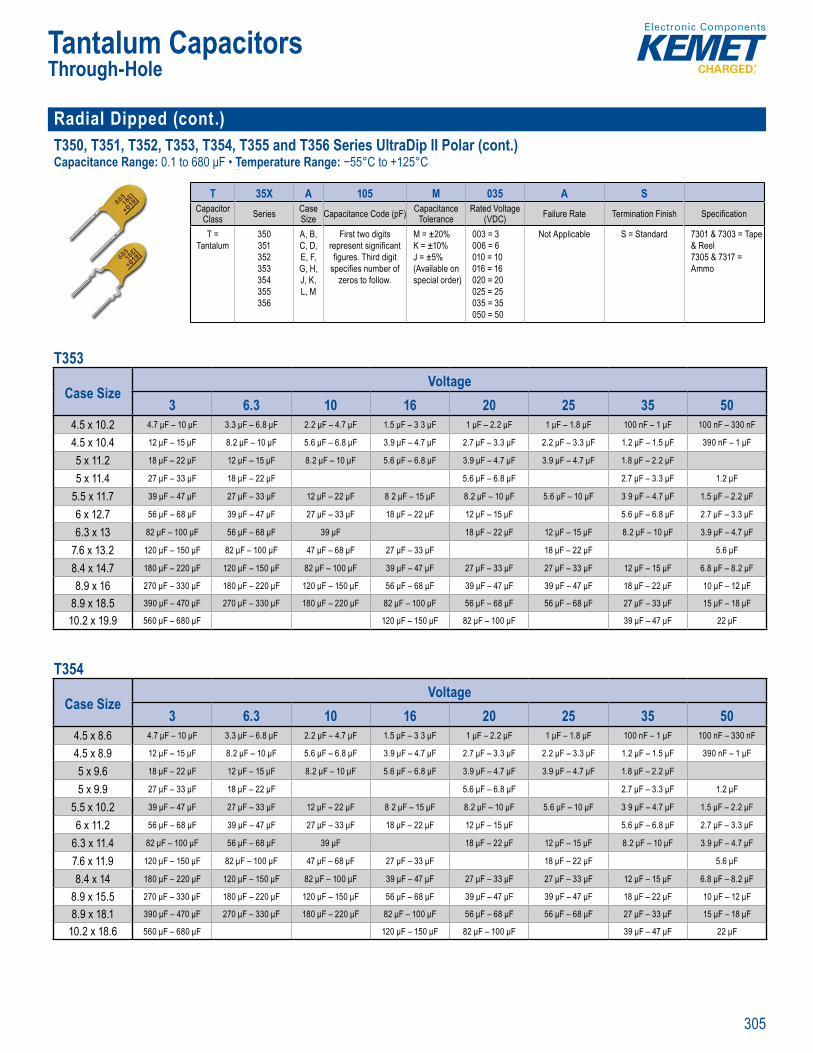
305
Tantalum CapacitorsThrough-Hole
Radial Dipped (cont.)T350, T351, T352, T353, T354, T355 and T356 Series UltraDip II Polar (cont.)Capacitance Range: 0.1 to 680 μF • Temperature Range: −55°C to +125°C
Or er g Information
T 35X A 105 M 035 A SCapacitor
Class Series Case Size Capacitance Code (pF) Capacitance
ToleranceRated Voltage
(VDC) Failure Rate Termination Finish Specifi cation
T = Tantalum
350351352353354355356
A, B, C, D, E, F, G, H, J, K, L, M
First two digits represent signifi cant fi gures. Third digit
specifi es number of zeros to follow.
M = ±20%K = ±10%J = ±5% (Available on special order)
003 = 3006 = 6010 = 10016 = 16020 = 20025 = 25035 = 35050 = 50
Not Applicable S = Standard 7301 & 7303 = Tape & Reel7305 & 7317 = Ammo
T353
Case SizeVoltage
3 6.3 10 16 20 25 35 504.5 x 10.2 4.7 μF – 10 μF 3.3 μF – 6.8 μF 2.2 μF – 4.7 μF 1.5 μF – 3 3 μF 1 μF – 2.2 μF 1 μF – 1.8 μF 100 nF – 1 μF 100 nF – 330 nF
4.5 x 10.4 12 μF – 15 μF 8.2 μF – 10 μF 5.6 μF – 6.8 μF 3.9 μF – 4.7 μF 2.7 μF – 3.3 μF 2.2 μF – 3.3 μF 1.2 μF – 1.5 μF 390 nF – 1 μF
5 x 11.2 18 μF – 22 μF 12 μF – 15 μF 8.2 μF – 10 μF 5.6 μF – 6.8 μF 3.9 μF – 4.7 μF 3.9 μF – 4.7 μF 1.8 μF – 2.2 μF
5 x 11.4 27 μF – 33 μF 18 μF – 22 μF 5.6 μF – 6.8 μF 2.7 μF – 3.3 μF 1.2 μF
5.5 x 11.7 39 μF – 47 μF 27 μF – 33 μF 12 μF – 22 μF 8 2 μF – 15 μF 8.2 μF – 10 μF 5.6 μF – 10 μF 3 9 μF – 4.7 μF 1.5 μF – 2.2 μF
6 x 12.7 56 μF – 68 μF 39 μF – 47 μF 27 μF – 33 μF 18 μF – 22 μF 12 μF – 15 μF 5.6 μF – 6.8 μF 2.7 μF – 3.3 μF
6.3 x 13 82 μF – 100 μF 56 μF – 68 μF 39 μF 18 μF – 22 μF 12 μF – 15 μF 8.2 μF – 10 μF 3.9 μF – 4.7 μF
7.6 x 13.2 120 μF – 150 μF 82 μF – 100 μF 47 μF – 68 μF 27 μF – 33 μF 18 μF – 22 μF 5.6 μF
8.4 x 14.7 180 μF – 220 μF 120 μF – 150 μF 82 μF – 100 μF 39 μF – 47 μF 27 μF – 33 μF 27 μF – 33 μF 12 μF – 15 μF 6.8 μF – 8.2 μF
8.9 x 16 270 μF – 330 μF 180 μF – 220 μF 120 μF – 150 μF 56 μF – 68 μF 39 μF – 47 μF 39 μF – 47 μF 18 μF – 22 μF 10 μF – 12 μF
8.9 x 18.5 390 μF – 470 μF 270 μF – 330 μF 180 μF – 220 μF 82 μF – 100 μF 56 μF – 68 μF 56 μF – 68 μF 27 μF – 33 μF 15 μF – 18 μF
10.2 x 19.9 560 μF – 680 μF 120 μF – 150 μF 82 μF – 100 μF 39 μF – 47 μF 22 μF
T354
Case SizeVoltage
3 6.3 10 16 20 25 35 504.5 x 8.6 4.7 μF – 10 μF 3.3 μF – 6.8 μF 2.2 μF – 4.7 μF 1.5 μF – 3 3 μF 1 μF – 2.2 μF 1 μF – 1.8 μF 100 nF – 1 μF 100 nF – 330 nF
4.5 x 8.9 12 μF – 15 μF 8.2 μF – 10 μF 5.6 μF – 6.8 μF 3.9 μF – 4.7 μF 2.7 μF – 3.3 μF 2.2 μF – 3.3 μF 1.2 μF – 1.5 μF 390 nF – 1 μF
5 x 9.6 18 μF – 22 μF 12 μF – 15 μF 8.2 μF – 10 μF 5.6 μF – 6.8 μF 3.9 μF – 4.7 μF 3.9 μF – 4.7 μF 1.8 μF – 2.2 μF
5 x 9.9 27 μF – 33 μF 18 μF – 22 μF 5.6 μF – 6.8 μF 2.7 μF – 3.3 μF 1.2 μF
5.5 x 10.2 39 μF – 47 μF 27 μF – 33 μF 12 μF – 22 μF 8 2 μF – 15 μF 8.2 μF – 10 μF 5.6 μF – 10 μF 3 9 μF – 4.7 μF 1.5 μF – 2.2 μF
6 x 11.2 56 μF – 68 μF 39 μF – 47 μF 27 μF – 33 μF 18 μF – 22 μF 12 μF – 15 μF 5.6 μF – 6.8 μF 2.7 μF – 3.3 μF
6.3 x 11.4 82 μF – 100 μF 56 μF – 68 μF 39 μF 18 μF – 22 μF 12 μF – 15 μF 8.2 μF – 10 μF 3.9 μF – 4.7 μF
7.6 x 11.9 120 μF – 150 μF 82 μF – 100 μF 47 μF – 68 μF 27 μF – 33 μF 18 μF – 22 μF 5.6 μF
8.4 x 14 180 μF – 220 μF 120 μF – 150 μF 82 μF – 100 μF 39 μF – 47 μF 27 μF – 33 μF 27 μF – 33 μF 12 μF – 15 μF 6.8 μF – 8.2 μF
8.9 x 15.5 270 μF – 330 μF 180 μF – 220 μF 120 μF – 150 μF 56 μF – 68 μF 39 μF – 47 μF 39 μF – 47 μF 18 μF – 22 μF 10 μF – 12 μF
8.9 x 18.1 390 μF – 470 μF 270 μF – 330 μF 180 μF – 220 μF 82 μF – 100 μF 56 μF – 68 μF 56 μF – 68 μF 27 μF – 33 μF 15 μF – 18 μF
10.2 x 18.6 560 μF – 680 μF 120 μF – 150 μF 82 μF – 100 μF 39 μF – 47 μF 22 μF
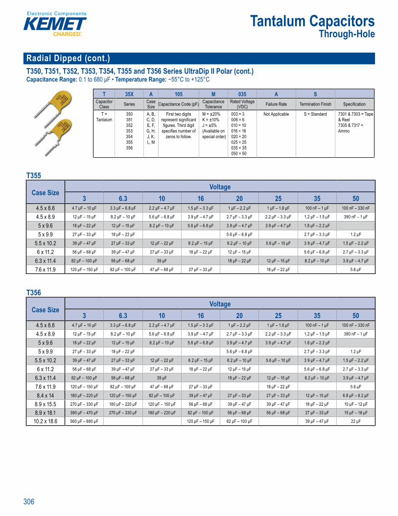
306
Tantalum CapacitorsThrough-Hole
Radial Dipped (cont.)T350, T351, T352, T353, T354, T355 and T356 Series UltraDip II Polar (cont.)Capacitance Range: 0.1 to 680 μF • Temperature Range: −55°C to +125°C
Or er g Informati n
T 35X A 105 M 035 A SCapacitor
Class Series Case Size Capacitance Code (pF) Capacitance
ToleranceRated Voltage
(VDC) Failure Rate Termination Finish Specifi cation
T = Tantalum
350351352353354355356
A, B, C, D, E, F, G, H, J, K, L, M
First two digits represent signifi cant fi gures. Third digit
specifi es number of zeros to follow.
M = ±20%K = ±10%J = ±5% (Available on special order)
003 = 3006 = 6010 = 10016 = 16020 = 20025 = 25035 = 35050 = 50
Not Applicable S = Standard 7301 & 7303 = Tape & Reel7305 & 7317 = Ammo
T355
Case SizeVoltage
3 6.3 10 16 20 25 35 504.5 x 8.6 4.7 μF – 10 μF 3.3 μF – 6.8 μF 2.2 μF – 4.7 μF 1.5 μF – 3 3 μF 1 μF – 2.2 μF 1 μF – 1.8 μF 100 nF – 1 μF 100 nF – 330 nF
4.5 x 8.9 12 μF – 15 μF 8.2 μF – 10 μF 5.6 μF – 6.8 μF 3.9 μF – 4.7 μF 2.7 μF – 3.3 μF 2.2 μF – 3.3 μF 1.2 μF – 1.5 μF 390 nF – 1 μF
5 x 9.6 18 μF – 22 μF 12 μF – 15 μF 8.2 μF – 10 μF 5.6 μF – 6.8 μF 3.9 μF – 4.7 μF 3.9 μF – 4.7 μF 1.8 μF – 2.2 μF
5 x 9.9 27 μF – 33 μF 18 μF – 22 μF 5.6 μF – 6.8 μF 2.7 μF – 3.3 μF 1.2 μF
5.5 x 10.2 39 μF – 47 μF 27 μF – 33 μF 12 μF – 22 μF 8 2 μF – 15 μF 8.2 μF – 10 μF 5.6 μF – 10 μF 3 9 μF – 4.7 μF 1.5 μF – 2.2 μF
6 x 11.2 56 μF – 68 μF 39 μF – 47 μF 27 μF – 33 μF 18 μF – 22 μF 12 μF – 15 μF 5.6 μF – 6.8 μF 2.7 μF – 3.3 μF
6.3 x 11.4 82 μF – 100 μF 56 μF – 68 μF 39 μF 18 μF – 22 μF 12 μF – 15 μF 8.2 μF – 10 μF 3.9 μF – 4.7 μF
7.6 x 11.9 120 μF – 150 μF 82 μF – 100 μF 47 μF – 68 μF 27 μF – 33 μF 18 μF – 22 μF 5.6 μF T356
Case SizeVoltage
3 6.3 10 16 20 25 35 504.5 x 8.6 4.7 μF – 10 μF 3.3 μF – 6.8 μF 2.2 μF – 4.7 μF 1.5 μF – 3 3 μF 1 μF – 2.2 μF 1 μF – 1.8 μF 100 nF – 1 μF 100 nF – 330 nF
4.5 x 8.9 12 μF – 15 μF 8.2 μF – 10 μF 5.6 μF – 6.8 μF 3.9 μF – 4.7 μF 2.7 μF – 3.3 μF 2.2 μF – 3.3 μF 1.2 μF – 1.5 μF 390 nF – 1 μF
5 x 9.6 18 μF – 22 μF 12 μF – 15 μF 8.2 μF – 10 μF 5.6 μF – 6.8 μF 3.9 μF – 4.7 μF 3.9 μF – 4.7 μF 1.8 μF – 2.2 μF
5 x 9.9 27 μF – 33 μF 18 μF – 22 μF 5.6 μF – 6.8 μF 2.7 μF – 3.3 μF 1.2 μF
5.5 x 10.2 39 μF – 47 μF 27 μF – 33 μF 12 μF – 22 μF 8 2 μF – 15 μF 8.2 μF – 10 μF 5.6 μF – 10 μF 3 9 μF – 4.7 μF 1.5 μF – 2.2 μF
6 x 11.2 56 μF – 68 μF 39 μF – 47 μF 27 μF – 33 μF 18 μF – 22 μF 12 μF – 15 μF 5.6 μF – 6.8 μF 2.7 μF – 3.3 μF
6.3 x 11.4 82 μF – 100 μF 56 μF – 68 μF 39 μF 18 μF – 22 μF 12 μF – 15 μF 8.2 μF – 10 μF 3.9 μF – 4.7 μF
7.6 x 11.9 120 μF – 150 μF 82 μF – 100 μF 47 μF – 68 μF 27 μF – 33 μF 18 μF – 22 μF 5.6 μF
8.4 x 14 180 μF – 220 μF 120 μF – 150 μF 82 μF – 100 μF 39 μF – 47 μF 27 μF – 33 μF 27 μF – 33 μF 12 μF – 15 μF 6.8 μF – 8.2 μF
8.9 x 15.5 270 μF – 330 μF 180 μF – 220 μF 120 μF – 150 μF 56 μF – 68 μF 39 μF – 47 μF 39 μF – 47 μF 18 μF – 22 μF 10 μF – 12 μF
8.9 x 18.1 390 μF – 470 μF 270 μF – 330 μF 180 μF – 220 μF 82 μF – 100 μF 56 μF – 68 μF 56 μF – 68 μF 27 μF – 33 μF 15 μF – 18 μF
10.2 x 18.6 560 μF – 680 μF 120 μF – 150 μF 82 μF – 100 μF 39 μF – 47 μF 22 μF
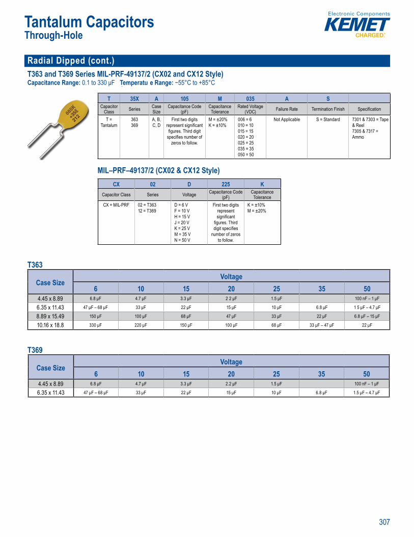
307
Tantalum CapacitorsThrough-Hole
Radial Dipped (cont.)T363 and T369 Series MIL-PRF-49137/2 (CX02 and CX12 Style) Capacitance Range: 0.1 to 330 μF Temperatu e Range: −55°C to +85°C
Order ng Info mation
T 35X A 105 M 035 A SCapacitor
Class Series Case Size
Capacitance Code (pF)
Capacitance Tolerance
Rated Voltage(VDC) Failure Rate Termination Finish Specifi cation
T = Tantalum
363369
A, B, C, D
First two digits represent signifi cant fi gures. Third digit
specifi es number of zeros to follow.
M = ±20%K = ±10%
006 = 6010 = 10015 = 15020 = 20025 = 25035 = 35050 = 50
Not Applicable S = Standard 7301 & 7303 = Tape & Reel7305 & 7317 = Ammo
MIL–PRF–49137/2 (CX02 & CX12 Style)
Or e I f mati
35X 1 5 35 Spacit Cas tanc
( )ap ci anc ed Volt
( )
T 63 A
i st two digits epre en sign fi can e g ecifi es numbe
M ±2 %
10 10
20 2025 253 3
7 0 & & e l7
CX 02 D 225 KCapacitor Class Series Voltage Capacitance Code
(pF)Capacitance
ToleranceCX = MIL-PRF 02 = T363
12 = T369D = 6 VF = 10 VH = 15 VJ = 20 VK = 25 VM = 35 VN = 50 V
First two digits represent signifi cant
fi gures. Third digit specifi es
number of zeros to follow.
K = ±10%M = ±20%
T363
Case SizeVoltage
6 10 15 20 25 35 504.45 x 8.89 6.8 μF 4.7 μF 3.3 μF 2 2 μF 1.5 μF 100 nF – 1 μF
6.35 x 11.43 47 μF – 68 μF 33 μF 22 μF 15 μF 10 μF 6.8 μF 1 5 μF – 4.7 μF
8.89 x 15.49 150 μF 100 μF 68 μF 47 μF 33 μF 22 μF 6.8 μF – 15 μF
10.16 x 18.8 330 μF 220 μF 150 μF 100 μF 68 μF 33 μF – 47 μF 22 μF
T369
Case SizeVoltage
6 10 15 20 25 35 504.45 x 8.89 6.8 μF 4.7 μF 3.3 μF 2.2 μF 1.5 μF 100 nF – 1 μF
6.35 x 11.43 47 μF – 68 μF 33 μF 22 μF 15 μF 10 μF 6.8 μF 1.5 μF – 4.7 μF
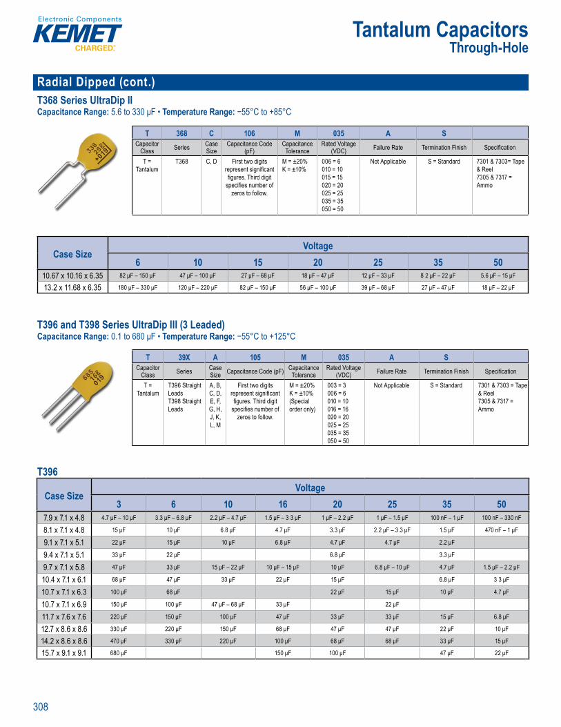
308
Tantalum CapacitorsThrough-Hole
Radial Dipped (cont.)T368 Series UltraDip IICapacitance Range: 5.6 to 330 μF • Temperature Range: −55°C to +85°C
Or er g nfo mation
T 368 C 106 M 035 A SCapacitor
Class Series Case Size
Capacitance Code (pF)
Capacitance Tolerance
Rated Voltage(VDC) Failure Rate Termination Finish Specifi cation
T = Tantalum
T368 C, D First two digits represent signifi cant fi gures. Third digit
specifi es number of zeros to follow.
M = ±20%K = ±10%
006 = 6010 = 10015 = 15020 = 20025 = 25035 = 35050 = 50
Not Applicable S = Standard 7301 & 7303= Tape & Reel7305 & 7317 = Ammo
Case SizeVoltage
6 10 15 20 25 35 5010.67 x 10.16 x 6.35 82 μF – 150 μF 47 μF – 100 μF 27 μF – 68 μF 18 μF – 47 μF 12 μF – 33 μF 8 2 μF – 22 μF 5.6 μF – 15 μF
13.2 x 11.68 x 6.35 180 μF – 330 μF 120 μF – 220 μF 82 μF – 150 μF 56 μF – 100 μF 39 μF – 68 μF 27 μF – 47 μF 18 μF – 22 μF
T396 and T398 Series UltraDip III (3 Leaded)Capacitance Range: 0.1 to 680 μF • Temperature Range: −55°C to +125°C
Or er g nfo mati n
T 39X A 105 M 035 A SCapacitor
Class Series Case Size Capacitance Code (pF) Capacitance
ToleranceRated Voltage
(VDC) Failure Rate Termination Finish Specifi cation
T = Tantalum
T396 Straight LeadsT398 Straight Leads
A, B, C, D, E, F, G, H, J, K, L, M
First two digits represent signifi cant fi gures. Third digit
specifi es number of zeros to follow.
M = ±20%K = ±10% (Special order only)
003 = 3006 = 6010 = 10016 = 16020 = 20025 = 25035 = 35050 = 50
Not Applicable S = Standard 7301 & 7303 = Tape & Reel7305 & 7317 = Ammo
T396
Case SizeVoltage
3 6 10 16 20 25 35 507.9 x 7.1 x 4.8 4.7 μF – 10 μF 3.3 μF – 6.8 μF 2.2 μF – 4.7 μF 1.5 μF – 3 3 μF 1 μF – 2.2 μF 1 μF – 1.5 μF 100 nF – 1 μF 100 nF – 330 nF
8.1 x 7.1 x 4.8 15 μF 10 μF 6.8 μF 4.7 μF 3.3 μF 2.2 μF – 3.3 μF 1.5 μF 470 nF – 1 μF
9.1 x 7.1 x 5.1 22 μF 15 μF 10 μF 6.8 μF 4.7 μF 4.7 μF 2.2 μF
9.4 x 7.1 x 5.1 33 μF 22 μF 6.8 μF 3.3 μF
9.7 x 7.1 x 5.8 47 μF 33 μF 15 μF – 22 μF 10 μF – 15 μF 10 μF 6.8 μF – 10 μF 4.7 μF 1.5 μF – 2.2 μF
10.4 x 7.1 x 6.1 68 μF 47 μF 33 μF 22 μF 15 μF 6.8 μF 3 3 μF
10.7 x 7.1 x 6.3 100 μF 68 μF 22 μF 15 μF 10 μF 4.7 μF
10.7 x 7.1 x 6.9 150 μF 100 μF 47 μF – 68 μF 33 μF 22 μF
11.7 x 7.6 x 7.6 220 μF 150 μF 100 μF 47 μF 33 μF 33 μF 15 μF 6.8 μF
12.7 x 8.6 x 8.6 330 μF 220 μF 150 μF 68 μF 47 μF 47 μF 22 μF 10 μF
14.2 x 8.6 x 8.6 470 μF 330 μF 220 μF 100 μF 68 μF 68 μF 33 μF 15 μF
15.7 x 9.1 x 9.1 680 μF 150 μF 100 μF 47 μF 22 μF
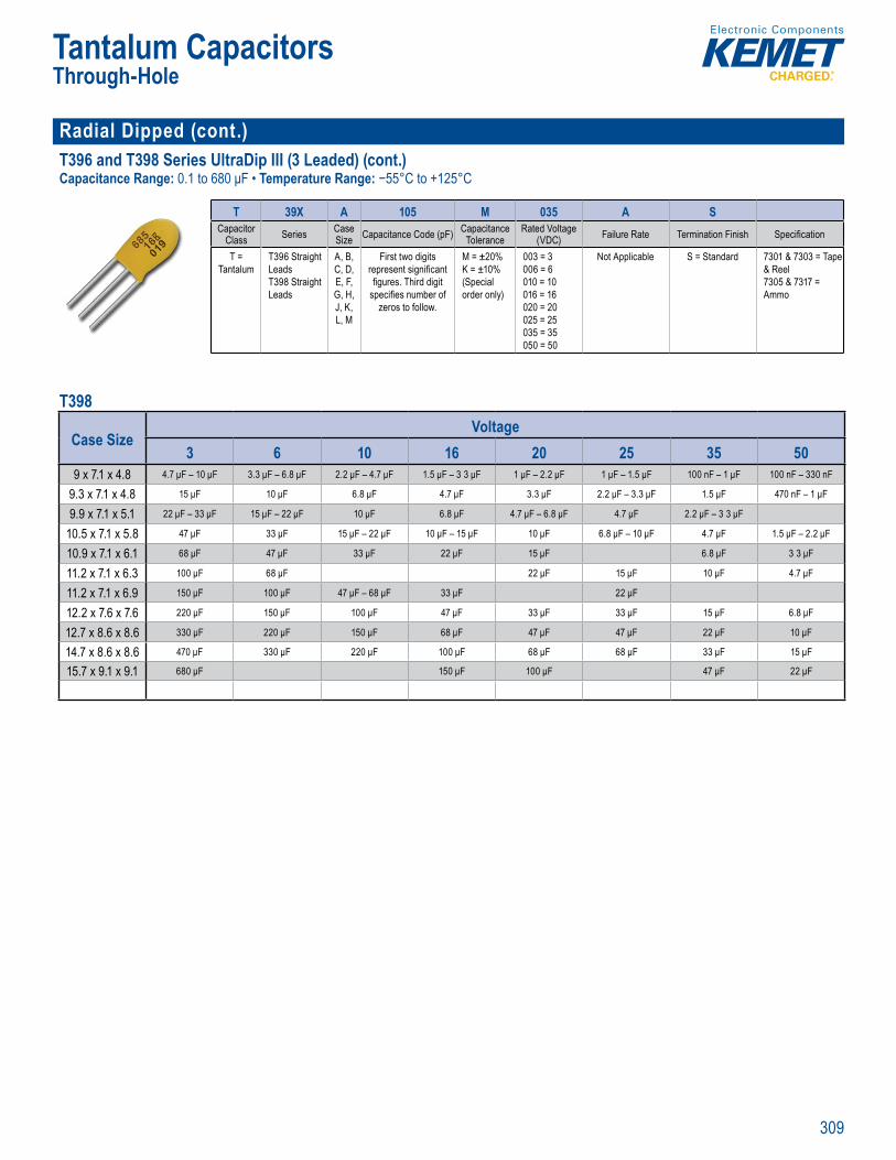
309
Tantalum CapacitorsThrough-Hole
Radial Dipped (cont.)T396 and T398 Series UltraDip III (3 Leaded) (cont.)Capacitance Range: 0.1 to 680 μF • Temperature Range: −55°C to +125°C
Or er g nfo mati n
T 39X A 105 M 035 A SCapacitor
Class Series Case Size Capacitance Code (pF) Capacitance
ToleranceRated Voltage
(VDC) Failure Rate Termination Finish Specifi cation
T = Tantalum
T396 Straight LeadsT398 Straight Leads
A, B, C, D, E, F, G, H, J, K, L, M
First two digits represent signifi cant fi gures. Third digit
specifi es number of zeros to follow.
M = ±20%K = ±10% (Special order only)
003 = 3006 = 6010 = 10016 = 16020 = 20025 = 25035 = 35050 = 50
Not Applicable S = Standard 7301 & 7303 = Tape & Reel7305 & 7317 = Ammo
T398
Case SizeVoltage
3 6 10 16 20 25 35 509 x 7.1 x 4.8 4.7 μF – 10 μF 3.3 μF – 6.8 μF 2.2 μF – 4.7 μF 1.5 μF – 3 3 μF 1 μF – 2.2 μF 1 μF – 1.5 μF 100 nF – 1 μF 100 nF – 330 nF
9.3 x 7.1 x 4.8 15 μF 10 μF 6.8 μF 4.7 μF 3.3 μF 2.2 μF – 3.3 μF 1.5 μF 470 nF – 1 μF
9.9 x 7.1 x 5.1 22 μF – 33 μF 15 μF – 22 μF 10 μF 6.8 μF 4.7 μF – 6.8 μF 4.7 μF 2.2 μF – 3 3 μF
10.5 x 7.1 x 5.8 47 μF 33 μF 15 μF – 22 μF 10 μF – 15 μF 10 μF 6.8 μF – 10 μF 4.7 μF 1.5 μF – 2.2 μF
10.9 x 7.1 x 6.1 68 μF 47 μF 33 μF 22 μF 15 μF 6.8 μF 3 3 μF
11.2 x 7.1 x 6.3 100 μF 68 μF 22 μF 15 μF 10 μF 4.7 μF
11.2 x 7.1 x 6.9 150 μF 100 μF 47 μF – 68 μF 33 μF 22 μF
12.2 x 7.6 x 7.6 220 μF 150 μF 100 μF 47 μF 33 μF 33 μF 15 μF 6.8 μF
12.7 x 8.6 x 8.6 330 μF 220 μF 150 μF 68 μF 47 μF 47 μF 22 μF 10 μF
14.7 x 8.6 x 8.6 470 μF 330 μF 220 μF 100 μF 68 μF 68 μF 33 μF 15 μF
15.7 x 9.1 x 9.1 680 μF 150 μF 100 μF 47 μF 22 μF
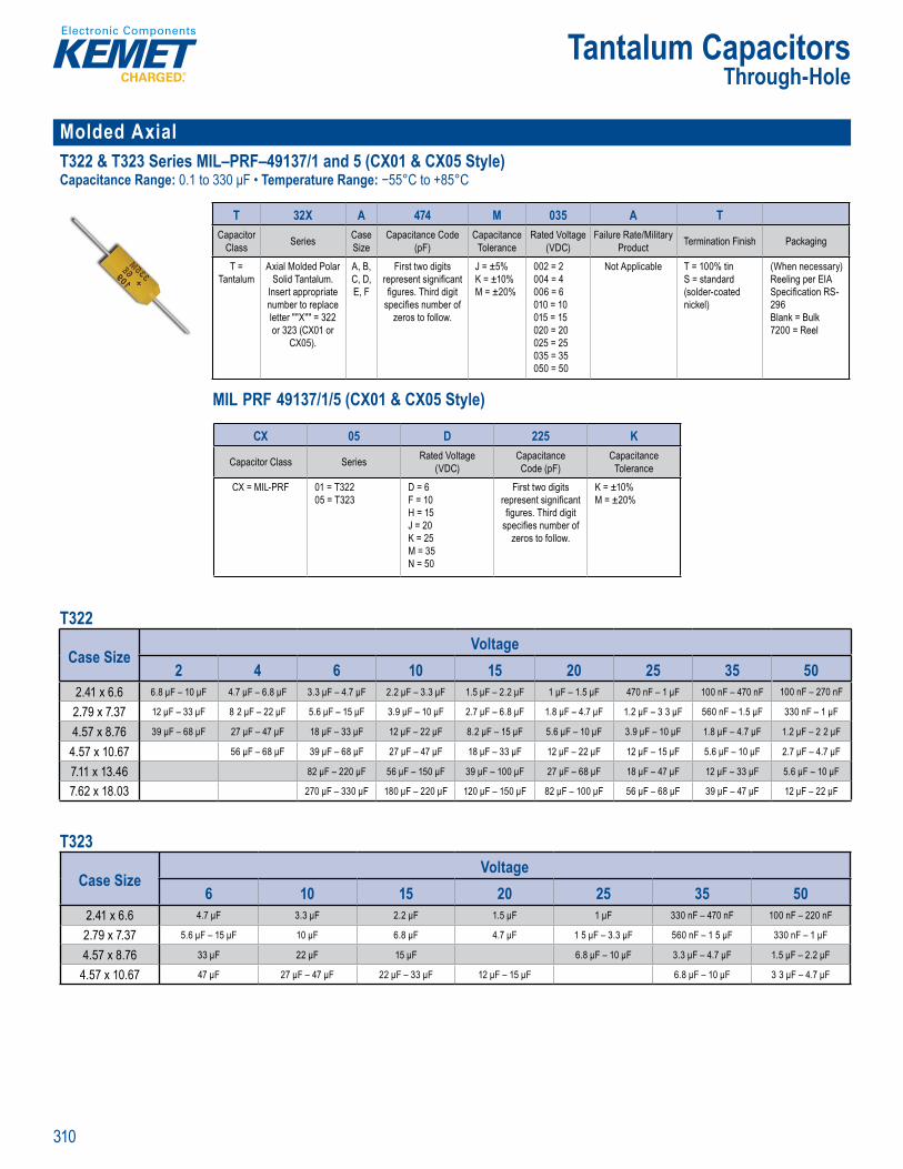
310
Tantalum CapacitorsThrough-Hole
Molded Axial T322 & T323 Series MIL–PRF–49137/1 and 5 (CX01 & CX05 Style)Capacitance Range: 0.1 to 330 μF • Temperature Range: −55°C to +85°C
Or er g nfo mation
T 32X A 474 M 035 A TCapacitor
Class Series Case Size
Capacitance Code (pF)
Capacitance Tolerance
Rated Voltage(VDC)
Failure Rate/Military Product Termination Finish Packaging
T = Tantalum
Axial Molded PolarSolid Tantalum.
Insert appropriate number to replace letter ""X"" = 322 or 323 (CX01 or
CX05).
A, B, C, D, E, F
First two digits represent signifi cant fi gures. Third digit
specifi es number of zeros to follow.
J = ±5% K = ±10% M = ±20%
002 = 2004 = 4006 = 6010 = 10015 = 15020 = 20025 = 25035 = 35050 = 50
Not Applicable T = 100% tinS = standard (solder-coated nickel)
(When necessary) Reeling per EIA Specifi cation RS-296Blank = Bulk 7200 = Reel
MIL PRF 49137/1/5 (CX01 & CX05 Style)
Ordering Information
a Cl ss
Ca S ze
itanc (pF)
acit ol rance
d VoVDC)
at roduct
T = nta
So d T n a um. n e t ppropria
nu be to eplac lette X 3 2 or 323 (CX or
CX05)
A B C D E, F
two present gnifi c gure . T i d digit
spec e num e o ze o to oll
J = ±5% ±10
M 2 %
2 = 2
6 60 5 15
20 2025 253 350 5
t Applic S s andar ( o de coate nic e )
ee ng pe E
Speci c t on 29B 72 0 Ree
MIL–PRF–49137/1/5 CX01 and CX05 Style
CX 05 D 225 K
Capacitor Class Series Rated Voltage(VDC)
Capacitance Code (pF)
Capacitance Tolerance
CX = MIL-PRF 01 = T32205 = T323
D = 6 F = 10 H = 15 J = 20 K = 25 M = 35 N = 50
First two digits represent signifi cant fi gures. Third digit
specifi es number of zeros to follow.
K = ±10% M = ±20%
T322
Case SizeVoltage
2 4 6 10 15 20 25 35 502.41 x 6.6 6.8 μF – 10 μF 4.7 μF – 6.8 μF 3.3 μF – 4.7 μF 2.2 μF – 3.3 μF 1.5 μF – 2.2 μF 1 μF – 1.5 μF 470 nF – 1 μF 100 nF – 470 nF 100 nF – 270 nF
2.79 x 7.37 12 μF – 33 μF 8 2 μF – 22 μF 5.6 μF – 15 μF 3.9 μF – 10 μF 2.7 μF – 6.8 μF 1.8 μF – 4.7 μF 1.2 μF – 3 3 μF 560 nF – 1.5 μF 330 nF – 1 μF
4.57 x 8.76 39 μF – 68 μF 27 μF – 47 μF 18 μF – 33 μF 12 μF – 22 μF 8.2 μF – 15 μF 5.6 μF – 10 μF 3.9 μF – 10 μF 1.8 μF – 4.7 μF 1.2 μF – 2 2 μF
4.57 x 10.67 56 μF – 68 μF 39 μF – 68 μF 27 μF – 47 μF 18 μF – 33 μF 12 μF – 22 μF 12 μF – 15 μF 5.6 μF – 10 μF 2.7 μF – 4.7 μF
7.11 x 13.46 82 μF – 220 μF 56 μF – 150 μF 39 μF – 100 μF 27 μF – 68 μF 18 μF – 47 μF 12 μF – 33 μF 5.6 μF – 10 μF
7.62 x 18.03 270 μF – 330 μF 180 μF – 220 μF 120 μF – 150 μF 82 μF – 100 μF 56 μF – 68 μF 39 μF – 47 μF 12 μF – 22 μF T323
Case SizeVoltage
6 10 15 20 25 35 502.41 x 6.6 4.7 μF 3.3 μF 2.2 μF 1.5 μF 1 μF 330 nF – 470 nF 100 nF – 220 nF
2.79 x 7.37 5.6 μF – 15 μF 10 μF 6.8 μF 4.7 μF 1 5 μF – 3.3 μF 560 nF – 1 5 μF 330 nF – 1 μF
4.57 x 8.76 33 μF 22 μF 15 μF 6.8 μF – 10 μF 3.3 μF – 4.7 μF 1.5 μF – 2.2 μF
4.57 x 10.67 47 μF 27 μF – 47 μF 22 μF – 33 μF 12 μF – 15 μF 6.8 μF – 10 μF 3 3 μF – 4.7 μF
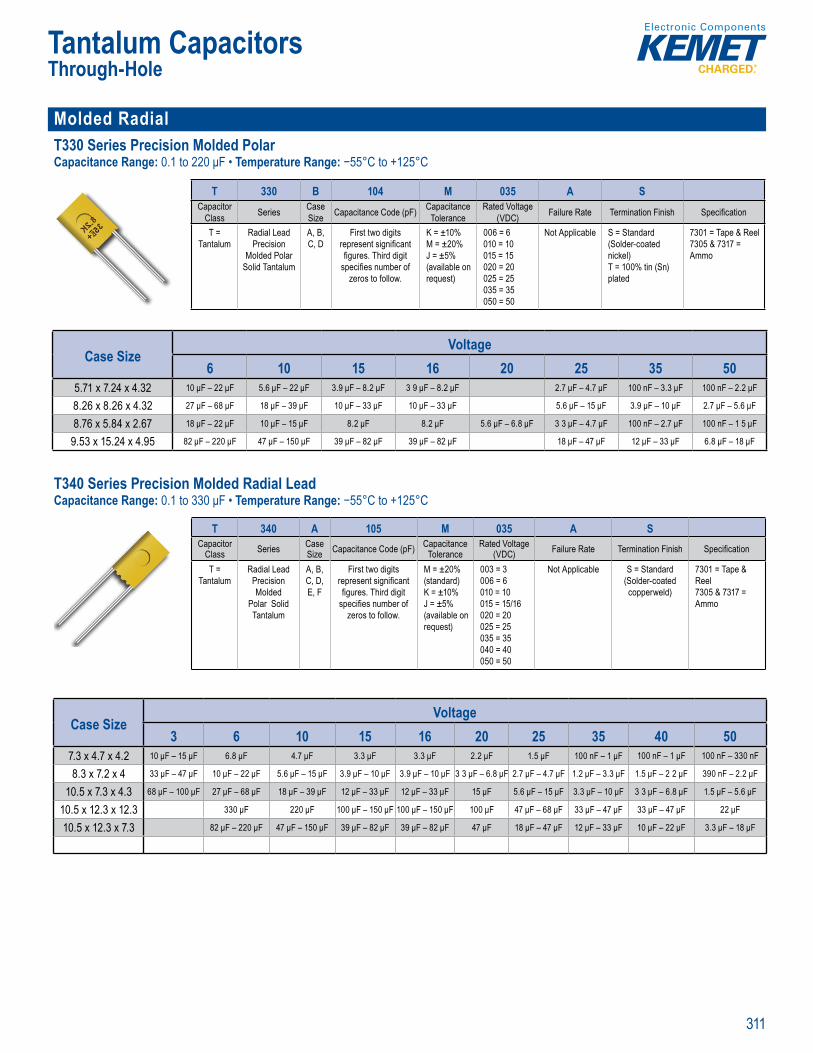
311
Tantalum CapacitorsThrough-Hole
Molded Radial T330 Series Precision Molded PolarCapacitance Range: 0.1 to 220 μF • Temperature Range: −55°C to +125°C
Order g nfo mati n
T 330 B 104 M 035 A SCapacitor
Class Series Case Size Capacitance Code (pF) Capacitance
ToleranceRated Voltage
(VDC) Failure Rate Termination Finish Specifi cation
T = Tantalum
Radial Lead Precision
Molded Polar Solid Tantalum
A, B, C, D
First two digits represent signifi cant fi gures. Third digit
specifi es number of zeros to follow.
K = ±10%M = ±20%J = ±5% (available on request)
006 = 6010 = 10015 = 15020 = 20025 = 25 035 = 35050 = 50
Not Applicable S = Standard (Solder-coated nickel)T = 100% tin (Sn) plated
7301 = Tape & Reel7305 & 7317 = Ammo
Case SizeVoltage
6 10 15 16 20 25 35 505.71 x 7.24 x 4.32 10 μF – 22 μF 5.6 μF – 22 μF 3.9 μF – 8.2 μF 3 9 μF – 8.2 μF 2.7 μF – 4.7 μF 100 nF – 3.3 μF 100 nF – 2.2 μF
8.26 x 8.26 x 4.32 27 μF – 68 μF 18 μF – 39 μF 10 μF – 33 μF 10 μF – 33 μF 5.6 μF – 15 μF 3.9 μF – 10 μF 2.7 μF – 5.6 μF
8.76 x 5.84 x 2.67 18 μF – 22 μF 10 μF – 15 μF 8.2 μF 8.2 μF 5.6 μF – 6.8 μF 3 3 μF – 4.7 μF 100 nF – 2.7 μF 100 nF – 1 5 μF
9.53 x 15.24 x 4.95 82 μF – 220 μF 47 μF – 150 μF 39 μF – 82 μF 39 μF – 82 μF 18 μF – 47 μF 12 μF – 33 μF 6.8 μF – 18 μF
T340 Series Precision Molded Radial Lead Capacitance Range: 0.1 to 330 μF • Temperature Range: −55°C to +125°C
Order g nfo mati n
T 340 A 105 M 035 A SCapacitor
Class Series Case Size Capacitance Code (pF) Capacitance
ToleranceRated Voltage
(VDC) Failure Rate Termination Finish Specifi cation
T = Tantalum
Radial Lead Precision Molded
Polar Solid Tantalum
A, B, C, D, E, F
First two digits represent signifi cant fi gures. Third digit
specifi es number of zeros to follow.
M = ±20% (standard)K = ±10%J = ±5% (available on request)
003 = 3006 = 6010 = 10015 = 15/16020 = 20025 = 25035 = 35040 = 40050 = 50
Not Applicable S = Standard (Solder-coated copperweld)
7301 = Tape & Reel7305 & 7317 = Ammo
Case SizeVoltage
3 6 10 15 16 20 25 35 40 507.3 x 4.7 x 4.2 10 μF – 15 μF 6.8 μF 4.7 μF 3.3 μF 3.3 μF 2.2 μF 1.5 μF 100 nF – 1 μF 100 nF – 1 μF 100 nF – 330 nF
8.3 x 7.2 x 4 33 μF – 47 μF 10 μF – 22 μF 5.6 μF – 15 μF 3.9 μF – 10 μF 3.9 μF – 10 μF 3 3 μF – 6.8 μF 2.7 μF – 4.7 μF 1.2 μF – 3.3 μF 1.5 μF – 2 2 μF 390 nF – 2.2 μF
10.5 x 7.3 x 4.3 68 μF – 100 μF 27 μF – 68 μF 18 μF – 39 μF 12 μF – 33 μF 12 μF – 33 μF 15 μF 5.6 μF – 15 μF 3.3 μF – 10 μF 3 3 μF – 6.8 μF 1.5 μF – 5.6 μF
10.5 x 12.3 x 12.3 330 μF 220 μF 100 μF – 150 μF 100 μF – 150 μF 100 μF 47 μF – 68 μF 33 μF – 47 μF 33 μF – 47 μF 22 μF
10.5 x 12.3 x 7.3 82 μF – 220 μF 47 μF – 150 μF 39 μF – 82 μF 39 μF – 82 μF 47 μF 18 μF – 47 μF 12 μF – 33 μF 10 μF – 22 μF 3.3 μF – 18 μF

312
Tantalum CapacitorsThrough-Hole
Molded Radial (cont.) T370 and T378 Series Micron MIL-PRF-4913716 (CX06 Style) Capacitance Range: T370: 0 68 to 220 μF, T378: 2.2 to 220 μF • Temperature Range: −55°C to +125°C
Order ng nf rmat on
T 37X D 475 M 035 A SCapacitor
Class Series Case Size Capacitance Code (pF) Capacitance
ToleranceRated Voltage
(VDC) Failure Rate Termination Finish Specifi cation
T = Tantalum
370378
C, D, E, F
First two digits represent signifi cant fi gures. Third digit
specifi es number of zeros to follow.
M = ±20%K = ±10%J = ±5%L = 40%, -20%
003 = 3004 = 4006 = 6.3010 = 10015 = 15020 = 20025 = 25035 = 35
Not Applicable S = Standard (Solder coated
nickel)
7301 = Tape & Reel
7305 & 7317 = Ammo
MIL-PRF-49137/6 (CX06 Style)
f
apacit l
Case z apacitanc
e nced Vol(
T = 0 C D
Fi st two digits eprese sign fi can fi gures. Third d gi
ecifi es umbe
M ±20K ±10 = ±5%
003 = 300 = 00 6010 = 00 5 = 5020 = 20025 = 25
S = Standard lder co
1 Ta el
5 & 73
CX 06 D 225 K
Capacitor Class Series Voltage Capacitance Code (pF)
Capacitance Tolerance
CX = MIL-PRF 06 = T378 A = 2 VB = 3 VC = 4 VD = 6 VF = 10 VH = 15 VJ = 20 VK = 25 VM = 35 V
First two digits represent signifi cant
fi gures. Third digit specifi es
number of zeros to follow.
K = ±10% M = ±20%
T370
Case SizeVoltage
3 4 6 10 15 20 25 354.7 x 5.72 x 1.91 15 μF 10 μF 6.8 μF 3.3 μF – 4.7 μF 2.2 μF 680 nF – 1.5 μF
5.59 x 7.73 x 2.79 47 μF 33 μF 22 μF 15 μF 10 μF 6.8 μF 2.2 μF – 4.7 μF
5.84 x 7.87 x 3.3 68 μF 47 μF 33 μF 22 μF 15 μF 10 μF 6.8 μF
9.53 x 12.07 x 3.81 220 μF 150 μF 100 μF 68 μF 47 μF 33 μF 10 μF – 22 μF
T378
Case SizeVoltage
3 4 6 10 15 20 25 355.59 x 7.73 x 2.79 47 μF 33 μF 22 μF 15 μF 10 μF 6.8 μF 2 2 μF – 4.7 μF
5.84 x 7.87 x 3.3 68 μF 47 μF 33 μF 22 μF 15 μF 10 μF 6.8 μF
9.53 x 12.07 x 3.81 220 μF 150 μF 100 μF 68 μF 47 μF 33 μF 10 μF – 22 μF

©2015 KEMET. All rights reserved.
Countries and Areas listed below represent KEMET operations throughout the world.
BulgariaChinaFinlandFranceGermanyHong KongIndia
IndonesiaItalyJapanMacedoniaMalaysia MexicoPortugal
SingaporeSouth KoreaSwedenTaiwanUnited KingdomUSA
Corporate HeadquartersKEMET Corporation2835 KEMET WaySimpsonville, SC 29681USA864.963.6300www.kemet.com
Electronic Components
CSG1015