Embed Size (px)
Citation preview
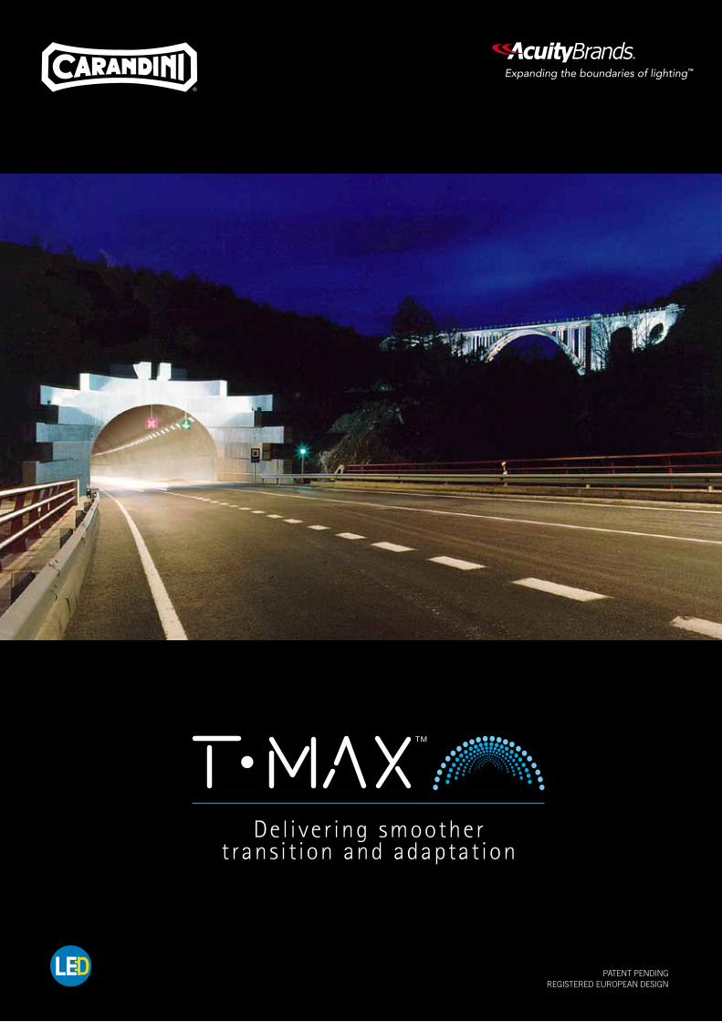
PATENT PENDING REGISTERED EUROPEAN DESIGN
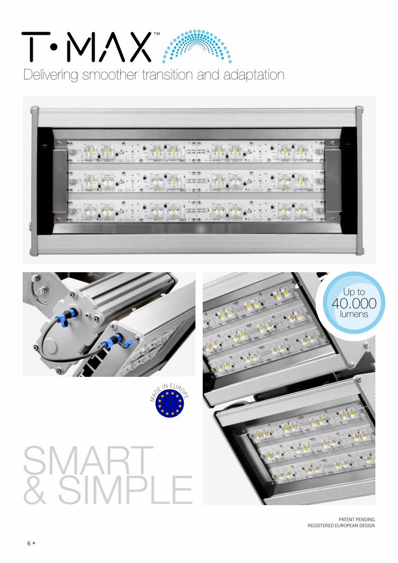
Del iver ing smoothert rans i t ion and adaptat ion
2 •
Tunnel Lighting turns Digital
• 3
With the revolution in Solid State Lighting it is imperative that as a lighting manufacturer we are ready to evolve in order to take advantage of these technological improvements and deliver solutions that add value and provide efficiency as well as quality of light.
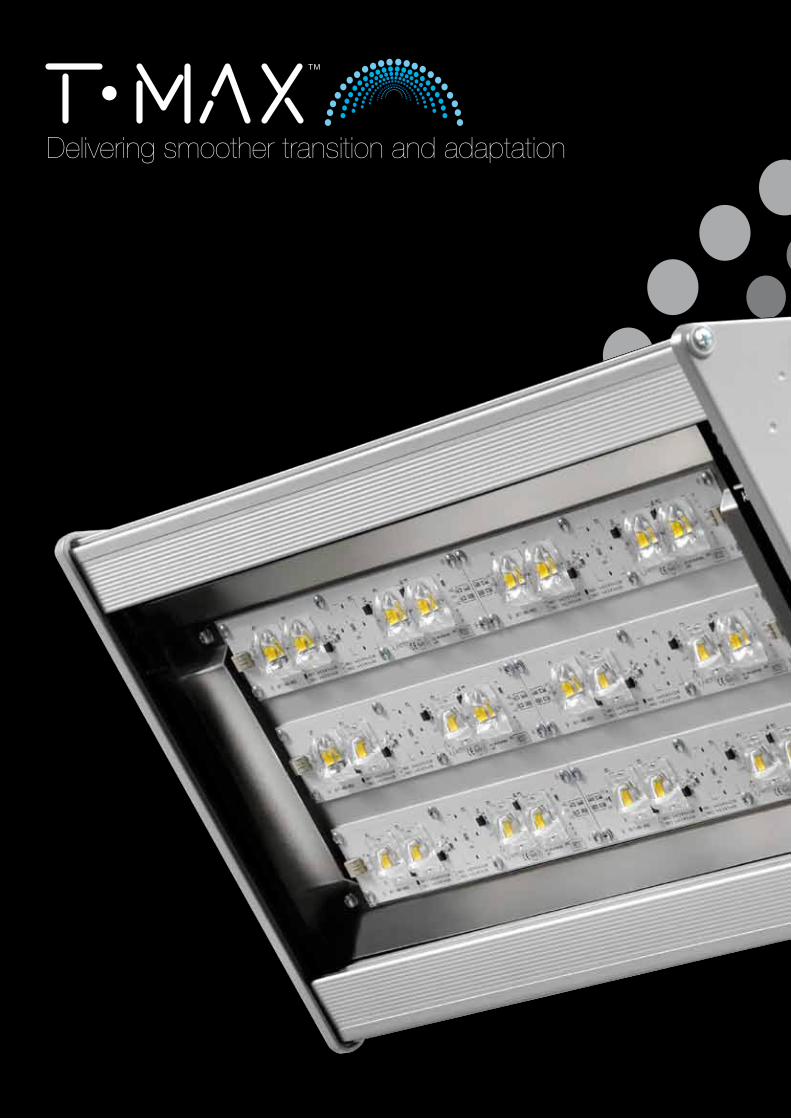
T·MAX™ is the latest development that has been created, by Carandini, using the latest in LED technology specifically for tunnels. The development has been shaped using the latest is solid state lighting and features the most reliable and efficient LED’s on the market to deliver a long system life. With a variety of mounting arrangements and optical packages T·MAX™ provides full flexibility that enables it to adapt in all tunnel or underpass environments.
During any product develop we are always conscious of what the lighting planners and users of the environment require from the lighting solution. The demands of the Project Team begin at the starting point when defining the main features of a new development. We must understand what the market requires from a new product and where the opportunities for improvement exist. This is one example of how technical expertise and customer interaction plays an important part inside Carandini: collaborating in applied research during the Product Development. This natural interaction with our customers provides the the platform for the development of a landmark evolution in tunnel lighting technology.
4 •
Delivering smoother transition and adaptation

• 5
✓ Modular design
✓ Thermal excellence
✓ 1 product ONE maintenance
✓ Optical performance
✓ Energy efficiency
6 •
PATENT PENDING REGISTERED EUROPEAN DESIGN
SMART & SIMPLE
Delivering smoother transition and adaptation
Up to
40.000lumens
MAD
E IN EUROPE
• 7
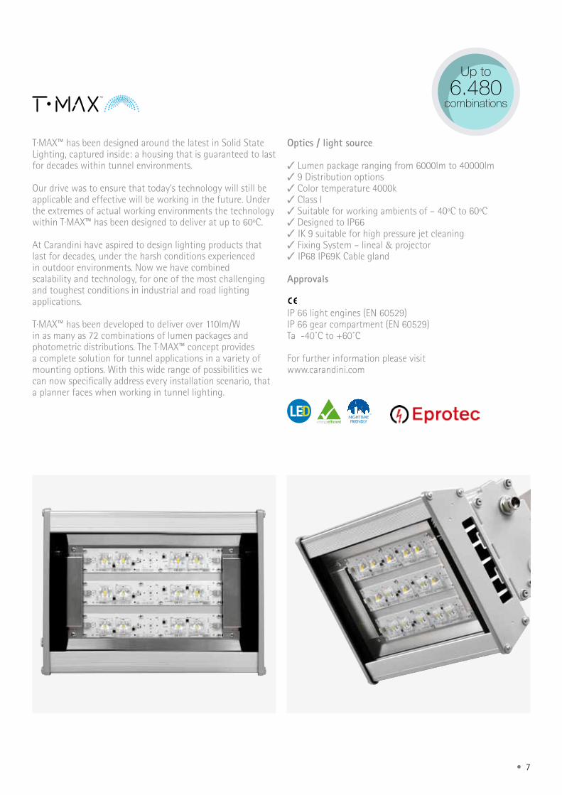
Up to
6.480combinations
T·MAX™ has been designed around the latest in Solid State Lighting, captured inside: a housing that is guaranteed to last for decades within tunnel environments.
Our drive was to ensure that today’s technology will still be applicable and effective will be working in the future. Under the extremes of actual working environments the technology within T·MAX™ has been designed to deliver at up to 60ºC.
At Carandini have aspired to design lighting products that last for decades, under the harsh conditions experienced in outdoor environments. Now we have combined scalability and technology, for one of the most challenging and toughest conditions in industrial and road lighting applications.
T·MAX™ has been developed to deliver over 110lm/W in as many as 72 combinations of lumen packages and photometric distributions. The T·MAX™ concept provides a complete solution for tunnel applications in a variety of mounting options. With this wide range of possibilities we can now specifically address every installation scenario, that a planner faces when working in tunnel lighting.
Optics / light source ✓ Lumen package ranging from 6000lm to 40000lm ✓ 9 Distribution options ✓ Color temperature 4000k ✓ Class I ✓ Suitable for working ambients of – 40ºC to 60ºC ✓ Designed to IP66 ✓ IK 9 suitable for high pressure jet cleaning ✓ Fixing System – lineal & projector ✓ IP68 IP69K Cable gland Approvals
IP 66 light engines (EN 60529) IP 66 gear compartment (EN 60529)Ta -40˚C to +60˚C
For further information please visit www.carandini.com

8 •
• 9
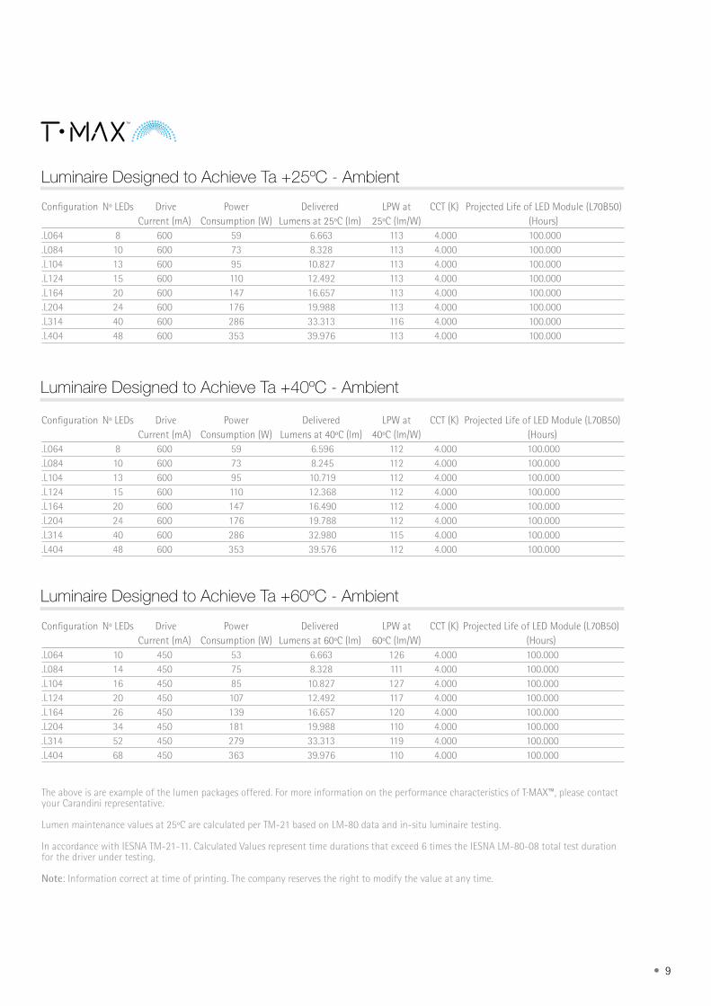
Luminaire Designed to Achieve Ta +40ºC - Ambient
Luminaire Designed to Achieve Ta +60ºC - Ambient
Luminaire Designed to Achieve Ta +25ºC - Ambient
The above is are example of the lumen packages offered. For more information on the performance characteristics of T·MAX™, please contact your Carandini representative.
Lumen maintenance values at 25ºC are calculated per TM-21 based on LM-80 data and in-situ luminaire testing.
In accordance with IESNA TM-21-11. Calculated Values represent time durations that exceed 6 times the IESNA LM-80-08 total test duration for the driver under testing.
Note: Information correct at time of printing. The company reserves the right to modify the value at any time.
Configuration Nº LEDs Drive Power Delivered LPW at CCT (K) Projected Life of LED Module (L70B50) Current (mA) Consumption (W) Lumens at 60ºC (lm) 60ºC (lm/W) (Hours).L064 10 450 53 6.663 126 4.000 100.000 .L084 14 450 75 8.328 111 4.000 100.000 .L104 16 450 85 10.827 127 4.000 100.000 .L124 20 450 107 12.492 117 4.000 100.000 .L164 26 450 139 16.657 120 4.000 100.000 .L204 34 450 181 19.988 110 4.000 100.000 .L314 52 450 279 33.313 119 4.000 100.000 .L404 68 450 363 39.976 110 4.000 100.000
Configuration Nº LEDs Drive Power Delivered LPW at CCT (K) Projected Life of LED Module (L70B50) Current (mA) Consumption (W) Lumens at 40ºC (lm) 40ºC (lm/W) (Hours).L064 8 600 59 6.596 112 4.000 100.000 .L084 10 600 73 8.245 112 4.000 100.000 .L104 13 600 95 10.719 112 4.000 100.000 .L124 15 600 110 12.368 112 4.000 100.000 .L164 20 600 147 16.490 112 4.000 100.000 .L204 24 600 176 19.788 112 4.000 100.000 .L314 40 600 286 32.980 115 4.000 100.000 .L404 48 600 353 39.576 112 4.000 100.000
Configuration Nº LEDs Drive Power Delivered LPW at CCT (K) Projected Life of LED Module (L70B50) Current (mA) Consumption (W) Lumens at 25ºC (lm) 25ºC (lm/W) (Hours).L064 8 600 59 6.663 113 4.000 100.000 .L084 10 600 73 8.328 113 4.000 100.000 .L104 13 600 95 10.827 113 4.000 100.000 .L124 15 600 110 12.492 113 4.000 100.000 .L164 20 600 147 16.657 113 4.000 100.000 .L204 24 600 176 19.988 113 4.000 100.000 .L314 40 600 286 33.313 116 4.000 100.000 .L404 48 600 353 39.976 113 4.000 100.000
10 •
Body Enclosure
Thermal Control
Optical enclosure Photometric distributions
Sealed for Life
Fixing
Maintenance
Cable Plug & Play
Gear Box
Finished
Water Ingress Protection
Impact Protection Electrical Specifications
Weight
Sleek profile manufactured from extruded anodized aluminium 6060 T6.
Flat tempered glass
Employing the 3 principles of thermal transfer. Conduction, via the aluminium housing. Convection, through the ventilations channels and, Radiation, from all critical components. The luminaire also adopts a Venturi effect which allows air movement over the glass lens which self cleans and provides enhanced lumen maintenance. The driver chamber is external and away from critical LED components. This ensures that the complete system life is maximised.
PMMA Acrylic lens.
.L1L7 => Long 60º & Wide 45º/15º
.L7L0 => Long 70º & Wide 60º/15º
.L5L6 => Long 70º & Narrow 20º
.L1L5 => Long 60º & Narrow 20º
.L1L6 => Long 60º & Narrow 30º
.L6L6 => Long 70º & Wide Symmetric 40º
.L1L1 => Long 60º & Narrow Symmetric 20º
.L7L7 => Long 70º & Narrow Symmetric 30º
.L8L7 => Asymmetric 50º
Ventilation filter (GORE®) that regulates the pressure changes caused by temperature variations internal and external of the luminaire. Eliminates condensation and stresses caused by these enviornmental changes and ensures the IP seal is maintained for the life time fo the product.
There are two types of mounting arrangements: .OL, OPL and .OSL => Adjustable brackets for the luminaire. .ZL => Fixed mounting as Z for the luminaire and the driver box.
Access to the gear is on the side of the luminaire via 4 Allen metric (5) screws. Cover designed to ensure IP66. Connection of luminaire via IP68 connectors. Earthing cable attached to the luminaire body.
Connection between the luminaire and gear are achieved by providing an insulated aerial and flexible EPR cable free from polyurethane halides with an IP68 connector for quick connection. The cable length is determined by the type of configuration selected.There are 2 types of cable: .FL3XX => 3-pin Cable .FL5XX => 5-pin Cable
The driver is supplied in a bespoke housing. Upon request, we can supply the gear on a separate ‘gear-tray’ which excludes the bespoke gear box. This allows onsite installation flexibility.Manufactured from extruded aluminum 6060 T6 anodized. Side covers are cast aluminum LM6 (EN AC-44100 AlSi12) low copper content <0.1%.
Anodized aluminum body. Side caps painted RAL-9006 Smooth Gloss (Silver Metallic).
According to EN 60529 Degree of protection of the luminaire => IP66 According to EN 60529 Degree of protection of the driver compartment (Gbox) => IP66
According to EN 62262, IK09 impact protection.
Input Voltage => 230V-240V / 50Hz - 60HzPower Factor > 0,9 at full loadTotal Armonic Distortion < 20% at full load.C-PROTEC => Surge protection system e-protec against permanent and transient surges up to a maximum rated current 10 KA. .C-FUS => At customer request can be supplied with an additional overprotection through a fuse
TMX.L064/L084/L104/L124 => 5,5kg TMX.L164/L204/L314/L404 => 9,2kg GBOX.L064/L084/L104/L124L164/L204 => 1,9kg GBOX.L314/L404 => 2,9kgNote: without fixture kits or drivers.
Guarantee Depends on project specifications (to consult)
Technical Specifications Luminaire
SPECIFICATIONS
• 11
Light Source
LED Technology
Light Control
Lifetime Operating temperature
Designed around the latest LED technology, with a luminous flux range from 6,000 lm to 40,000 lm and a color temperature of 4,000K. (Neutral White, nw). CRI 70.Operating current 600mA Ta +40ºC.
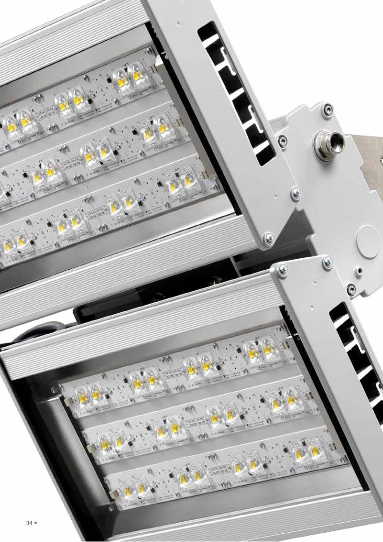
Utilises 8 to 48 LEDS that are attached to the PCB in a zero oxygen atmosphere. This process ensures its robustness and relaibilty. All LED modules are stress tested prior to integration into the luminaire - this ensures reliability and eliminates on site failures.
Through programmable devices with regulation from power box and regulation by DALI protocol, the lighting is managed more efficiently, minimizing consumption and maximizing performance. This control is a key part of the energy efficiency of the luminaire.
The lifetime of the T · MAX is 100,000 hours L70B50 Standard .D01 => -40°C / +40°C. Optional .D03=> -40°C / +60°C.
Technical Specifications LED
Compliance with Standards
UNE-EN 61547:2011Equipment for general lighting purposes - EMC immunity requirements UNE-EN 55015:2013Limits and methods of measurement of radio disturbance characteristics of electrical lighting and similar equipment UNE-EN 61000-3-2:2006Electromagnetic compatibility (EMC) -- Part 3-2: Limits - Limits for harmonic current emissions (equipment input current <= 16 A per phase) (IEC 61000-3-2:2005). UNE-EN 61000-3-3:2013Electromagnetic compatibility (EMC) - Part 3-3: Limits - Limitation of voltage changes, voltage fluctuations and flicker in public low-voltage supply systems, for equipment with rated current <= 16 A per phase and not subject to conditional connection UNE-EN 62262:2002Degrees of protection provided by enclosures for electrical equipment against external mechanical impacts (IK code). UNE-EN 60529:1992/A2:2013Degrees of protection provided by enclosures (IP code) UNE-EN 62384:2007D.C. or A.C. supplied electronic control gear for LED modules - Performance requirements (IEC 62348:2006). UNE-EN 62493:2011Assessment of lighting equipment related to human exposure to electromagnetic fields DIN 40050-9Road vehicles; degrees of protection (IP-code); protection against foreign objects; water and contact; electrical equipment ANSI C136.31-2010American National Standard for Roadway and Area Lighting Equipment— Luminaire Vibration
IEC 62722-2-1Luminaire performance – Part 2-1: Particular requirements for LED luminaires IEC 62717LED modules for general lighting – Performance requirements European Directive - 2006/95/EC (Low Voltage) European Directive - 2004/108/EC (EMC) European Directive - 98/37/EC (Machinery): CE Marked European Directive on Waste Electrical and Electronic Equipment (WEEE) Directive 2012/19/EU UNE-EN ISO 9227:2007Corrosion tests in artificial atmospheres - Salt spray tests (ISO 9227:2006)
12 •
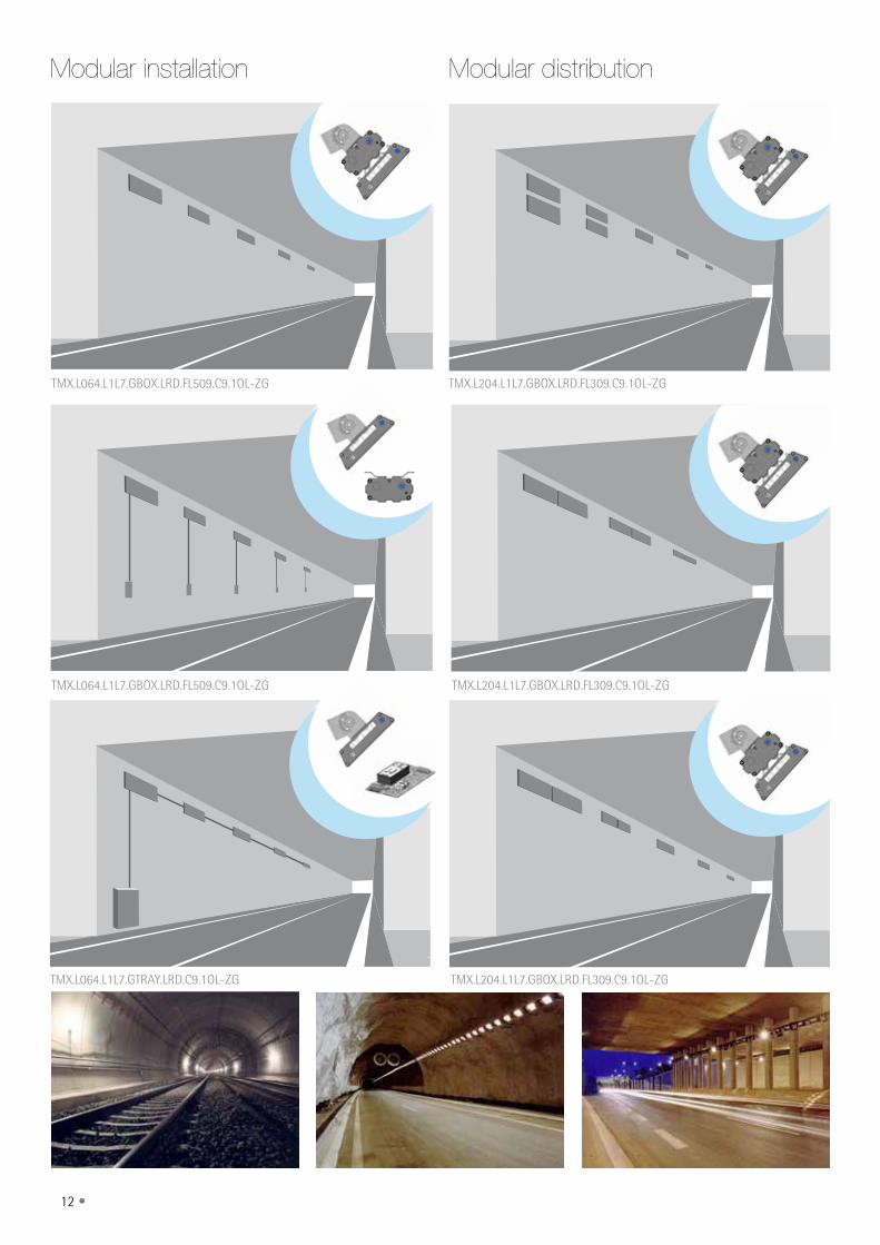
Modular installation Modular distribution
TMX.L064.L1L7.GBOX.LRD.FL509.C9.1OL-ZG
TMX.L064.L1L7.GBOX.LRD.FL509.C9.1OL-ZG
TMX.L064.L1L7.GTRAY.LRD.C9.1OL-ZG
TMX.L204.L1L7.GBOX.LRD.FL309.C9.1OL-ZG
TMX.L204.L1L7.GBOX.LRD.FL309.C9.1OL-ZG
TMX.L204.L1L7.GBOX.LRD.FL309.C9.1OL-ZG
• 13
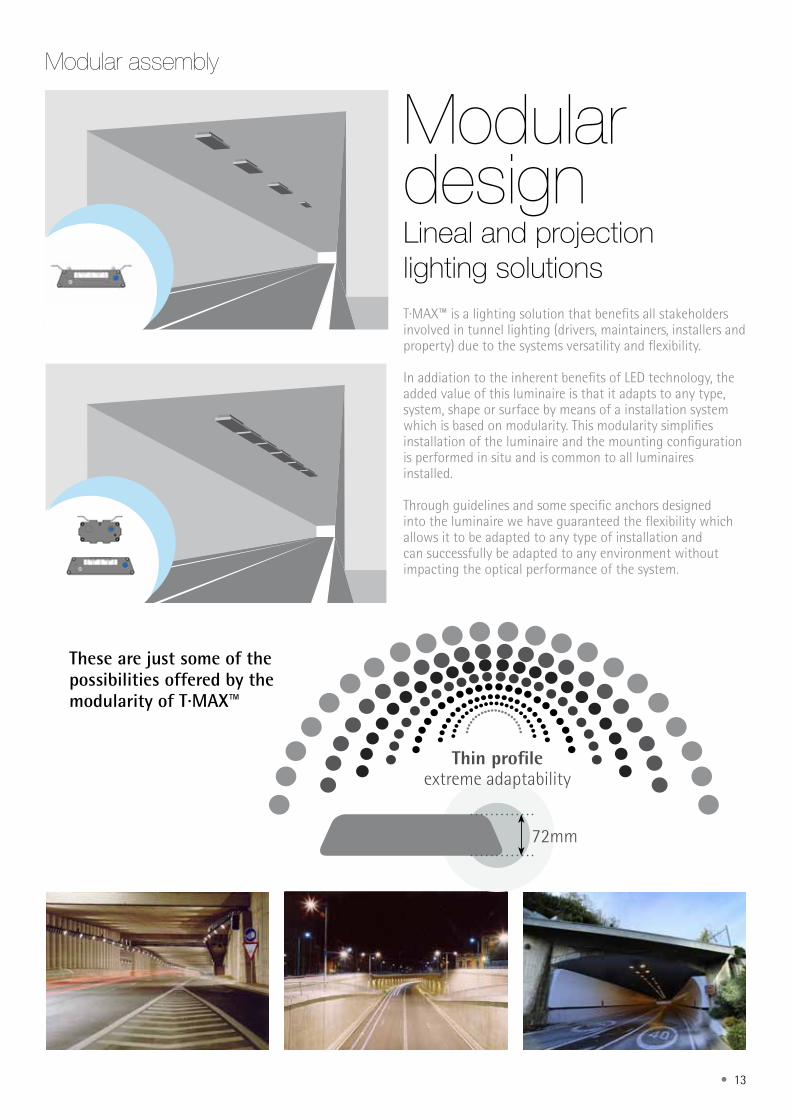
T·MAX™ is a lighting solution that benefits all stakeholders involved in tunnel lighting (drivers, maintainers, installers and property) due to the systems versatility and flexibility.
In addiation to the inherent benefits of LED technology, the added value of this luminaire is that it adapts to any type, system, shape or surface by means of a installation system which is based on modularity. This modularity simplifies installation of the luminaire and the mounting configuration is performed in situ and is common to all luminaires installed.
Through guidelines and some specific anchors designed into the luminaire we have guaranteed the flexibility which allows it to be adapted to any type of installation and can successfully be adapted to any environment without impacting the optical performance of the system.
Modular design
Modular assembly
Lineal and projectionlighting solutions
These are just some of the possibilities offered by the modularity of T·MAX™
Thin profile extreme adaptability
72mm
14 •
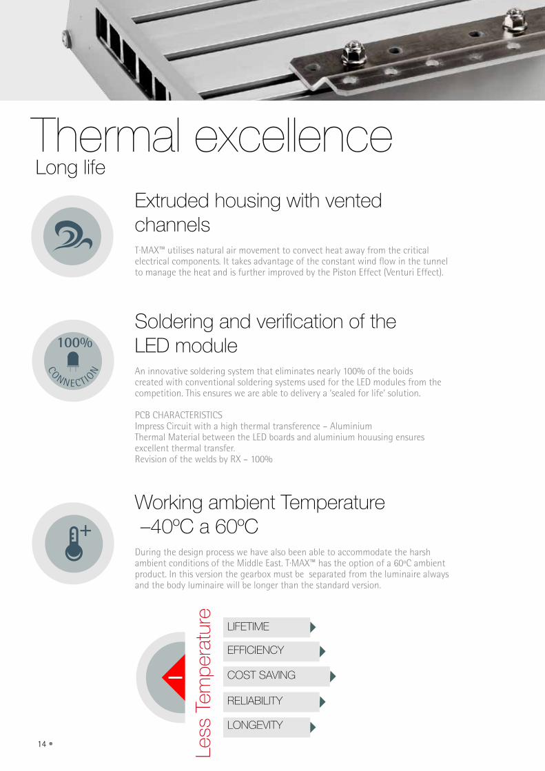
Thermal excellenceExtruded housing with vented channelsT·MAX™ utilises natural air movement to convect heat away from the critical electrical components. It takes advantage of the constant wind flow in the tunnel to manage the heat and is further improved by the Piston Effect (Venturi Effect).
Working ambient Temperature –40ºC a 60ºCDuring the design process we have also been able to accommodate the harsh ambient conditions of the Middle East. T·MAX™ has the option of a 60ºC ambient product. In this version the gearbox must be separated from the luminaire always and the body luminaire will be longer than the standard version.
Soldering and verification of the LED moduleAn innovative soldering system that eliminates nearly 100% of the boids created with conventional soldering systems used for the LED modules from the competition. This ensures we are able to delivery a ‘sealed for life’ solution.
PCB CHARACTERISTICSImpress Circuit with a high thermal transference – Aluminium Thermal Material between the LED boards and aluminium houusing ensures excellent thermal transfer.Revision of the welds by RX – 100%
100%
CONNECT I ON
Long life
Less
Tem
pera
ture
LongEviTy
EffiCiEnCy
CoST SAving
RELiAbiLiTy
LifETimE
• 15
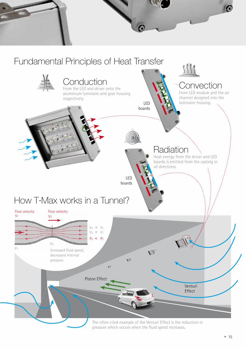
fundamental Principles of Heat Transfer
From the LED and driver onto the aluminium luminaire and gear housing respectively.
Conduction
VenturiEffect
Piston Effect
Flow velocity Flow velocity
Increased fluid speed,decreased internal pressure.
V1 V2
P2 ˂ P1
A2
V2
˂>
A1
V1
P2
P1
The often cited example of the Venturi Effect is the reduction in pressure which occurs when the fluid speed increases.
From LED module and the air channel designed into the luminaire housing.
Convection
RadiationHeat energy from the driver and LED boards is emitted from the casting in all directions.
LED boards
How T·max works in a Tunnel?
LED boards
16 •
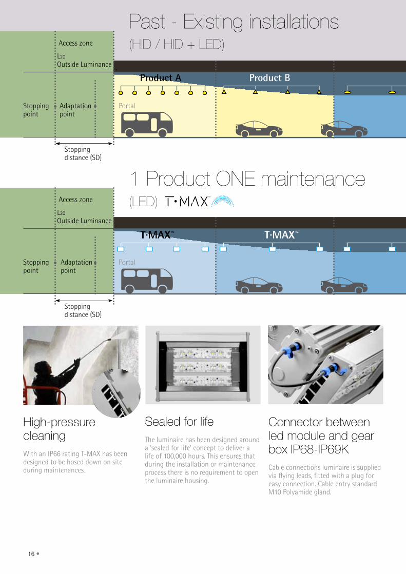
High-pressure cleaningWith an IP66 rating T-MAX has been designed to be hosed down on site during maintenances.
Connector between led module and gear box iP68-iP69K Cable connections luminaire is supplied via flying leads, fitted with a plug for easy connection. Cable entry standard M10 Polyamide gland.
Sealed for lifeThe luminaire has been designed around a ‘sealed for life’ concept to deliver a life of 100,000 hours. This ensures that during the installation or maintenance process there is no requirement to open the luminaire housing.
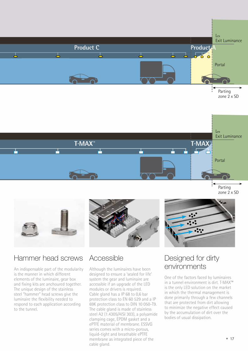
Access zone
Adaptation point
Stoppingdistance (SD)
Stoppingdistance (SD)
Portal
Product A Product B
Stoppingpoint
L20
Outside Luminance
Past - Existing installations(HID / HID + LED)
Access zone
Adaptation point
T·MAX™ T·MAX™
PortalStoppingpoint
L20
Outside Luminance
1 Product ONE maintenance(LED)
• 17
Hammer head screwsAn indispensable part of the modularity is the manner in which different elements of the luminaire, gear box and fixing kits are anchoured together. The unique design of the stainless steel “hammer” head screws give the luminaire the flexibility needed to respond to each application according to the tunnel.
Designed for dirty environmentsOne of the factors faced by luminaires in a tunnel environment is dirt. T·MAX™ is the only LED solution on the market in which the thermal management isdone primarily through a few channels that are protected from dirt allowing to minimize the negative effect caused by the accumulation of dirt over the bodies of usual dissipation.
AccessibleAlthough the luminaires have been designed to ensure a ‘sealed for life’ system the gear and luminaire are accessible if an upgrade of the LED modules or drivers is required.Cable gland has a IP 68 to 0,6 bar protection class to EN 60 529 and a IP 69K protection class to DIN 10 050-T9. The cable gland is made of stainless steel A2 (1.4305/AISI 303), a polyamide clamping cage, EPDM gasket and a ePTFE material of membrane. ESSVG series comes with a micro-porous, liquid-tight and breathable ePTFE membrane as integrated piece of the cable gland.
Parting zone 2 x SD
Parting zone 2 x SD
Product AProduct C
Portal
Lex
Exit Luminance
Past - Existing installations(HID / HID + LED)
T·MAX™
Portal
Lex
Exit Luminance
1 Product ONE maintenance(LED)
T·MAX™
18 •
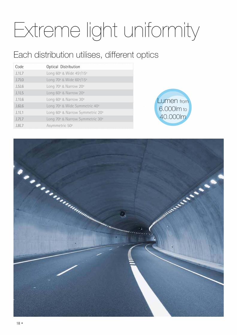
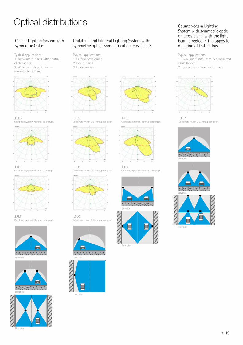
Extreme light uniformityEach distribution utilises, different opticsCode Optical Distribution
.L1L7 Long 60º & Wide 45º/15º
.L7L0 Long 70º & Wide 60º/15º
.L5L6 Long 70º & Narrow 20º
.L1L5 Long 60º & Narrow 20º
.L1L6 Long 60º & Narrow 30º
.L6L6 Long 70º & Wide Symmetric 40º
.L1L1 Long 60º & Narrow Symmetric 20º
.L7L7 Long 70º & Narrow Symmetric 30º
.L8L7 Asymmetric 50º
Lumen from 6.000lm to 40.000lm
• 19
Typical applications:1. Lateral positioning.2. Box tunnels.3. Underpasses.
optical distributions
.L1L5Coordinate system C-Gamma, polar graph.
.L7L0Coordinate system C-Gamma, polar graph.
.L1L6Coordinate system C-Gamma, polar graph.
.L1L7Coordinate system C-Gamma, polar graph.
.L5L6 Coordinate system C-Gamma, polar graph.
Typical applications:1. Two-lane tunnels with central cable ladder.2. Wide tunnels with two or more cable ladders.
.L6L6 Coordinate system C-Gamma, polar graph.
.L1L1Coordinate system C-Gamma, polar graph.
.L7L7 Coordinate system C-Gamma, polar graph.
Typical applications:1. Two-lane tunnel with decentralized cable ladder.2. Two or more lane box tunnels.
.L8L7 Coordinate system C-Gamma, polar graph.
Elevation
Elevation
Elevation
Elevation Elevation
Elevation
Floor plan
Floor plan
Floor plan
Floor plan
Ceiling Lighting System with symmetric Optic.
Unilateral and bilateral Lighting System with symmetric optic, asymmetrical on cross plane.
Counter-beam Lighting System with symmetric optic on cross plane, with the light beam directed in the opposite direction of traffic flow.
20 •
• 21
Lighting within tunnel environments is used 24 hours a day. Reducing energy consumption and costs is critical. T·MAX™ is designed for maximum performance and uniformity with minimum power consumption.
The choice of quality and cutting-edge LEDS attached to the optimal and efficient control of the emitted light and photometric flexibility, makes T·MAX™ the most efficient solution for tunnel lighting.
The lowest energy consumption
T·MAX™ T·MAX™ T·MAX™Energy savings Energy savings
This values are representatives
Energy savings
100W HPS/TMX LEDDIFFERENSE WATT/UNIT- 56W
250W HPS/TMX LEDDIFFERENSE WATT/UNIT- 99W
400W HPS/TMX LEDDIFFERENSE WATT/UNIT- 82W
Comparison HPS / LED
19% 36% 48%
HPS HPS HPS LED LED LED
ConsumptionSystem failuresmaintenance
LifespanWarrantySecuritySaving
Investment return
22 •
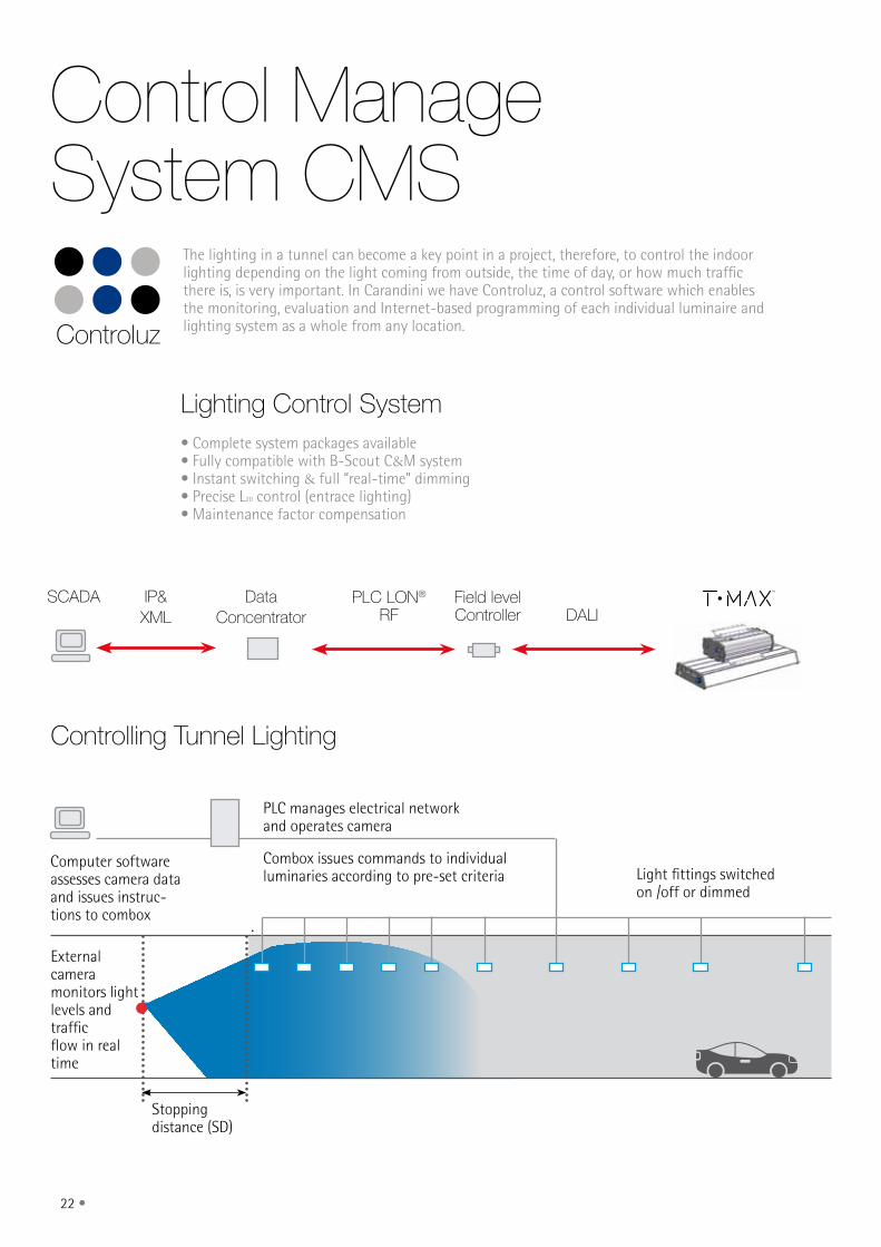
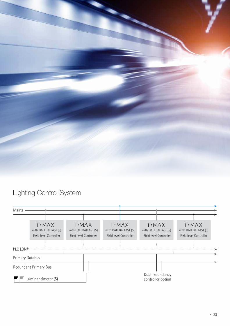
Control Manage System CMS
The lighting in a tunnel can become a key point in a project, therefore, to control the indoor lighting depending on the light coming from outside, the time of day, or how much traffic there is, is very important. In Carandini we have Controluz, a control software which enables the monitoring, evaluation and Internet-based programming of each individual luminaire and lighting system as a whole from any location.
Lighting Control System• Complete system packages available• Fully compatible with B-Scout C&M system• Instant switching & full “real-time” dimming• Precise L20 control (entrace lighting)• Maintenance factor compensation
Controlling Tunnel Lighting
Controluz
Stoppingdistance (SD)
Light fittings switchedon /off or dimmed
External camera monitors lightlevels and trafficflow in real time
PLC manages electrical networkand operates camera
Computer software assesses camera data and issues instruc-tions to combox
Combox issues commands to individualluminaries according to pre-set criteria
iP&XmL
PLC Lon®
Rf DALiSCADA Data
Concentratorfield level Controller
• 23
Lighting Control System
Mains
PLC LON®
Primary Databus
Redundant Primary Bus
Luminancimeter (S)Dual redundancy controller option
with DALI BALLAST (S) with DALI BALLAST (S) with DALI BALLAST (S) with DALI BALLAST (S) with DALI BALLAST (S)
Field level Controller Field level Controller Field level Controller Field level Controller Field level Controller
24 •
A tunnel luminaire is under the toughest conditions: the gases emitted by automobiles, oils and fuels, moisture and condensation, (marine, ice Potash) salts, dust in suspension, soot, detergents used for cleaning, constant vibrations (vehicle, weather conditions and effector Venturi).
We have paid particular attention to the materials used and its characteristics of endurance, resistance to vibration and corrosion, ensuring a minimum influence of the effects that cause such extreme conditions of work in the fixture.
Our total commitment to quality is reflected in that T·MAX™ is sealed for life, a minimum life of 100,000 h L70B50.
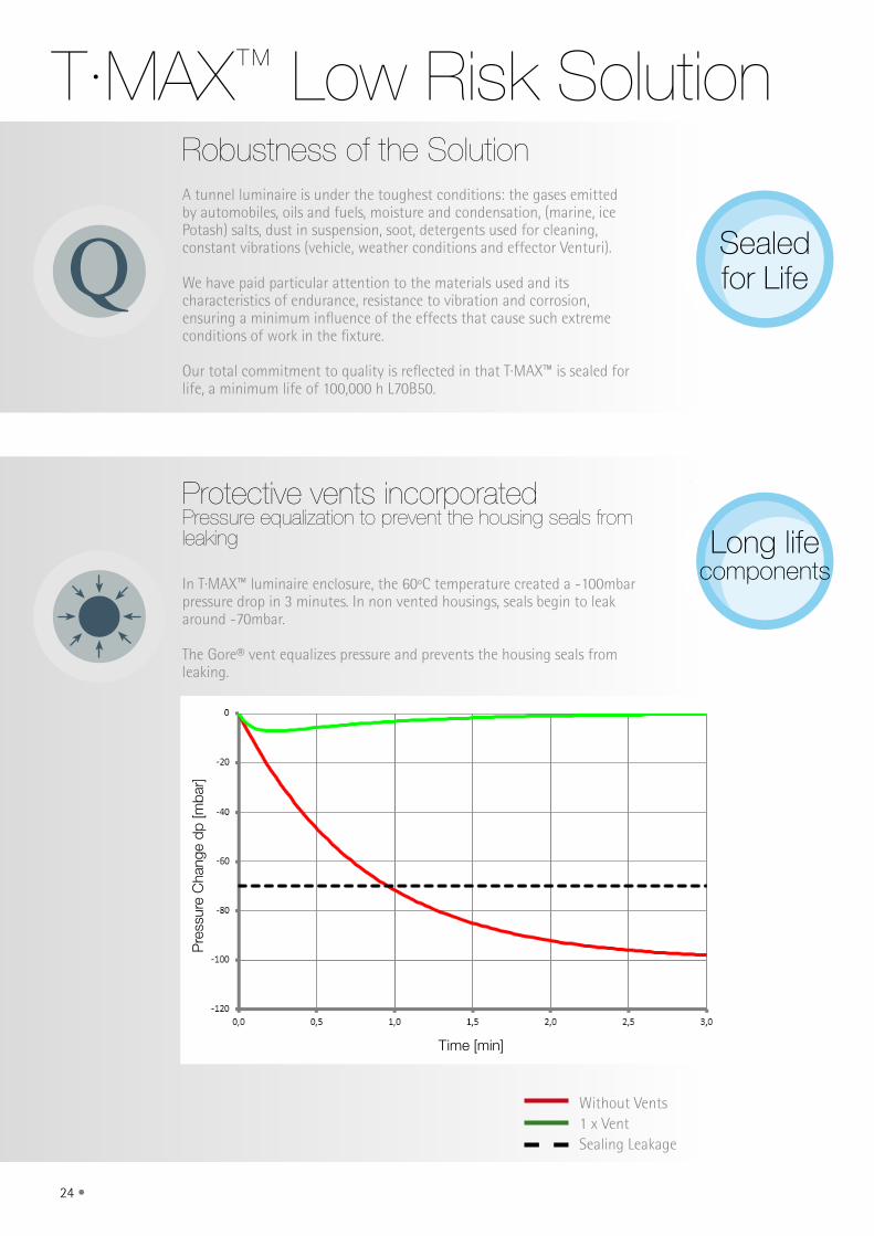
T·MAX™ Low Risk SolutionRobustness of the Solution
Protective vents incorporatedPressure equalization to prevent the housing seals from leaking
In T·MAX™ luminaire enclosure, the 60ºC temperature created a -100mbar pressure drop in 3 minutes. In non vented housings, seals begin to leak around -70mbar.
The Gore® vent equalizes pressure and prevents the housing seals from leaking.
Without Vents1 x VentSealing Leakage
Sealed for Life
Long life components
Q
Time [min]
Pre
ssur
e C
hang
e dp
[mba
r]
• 25
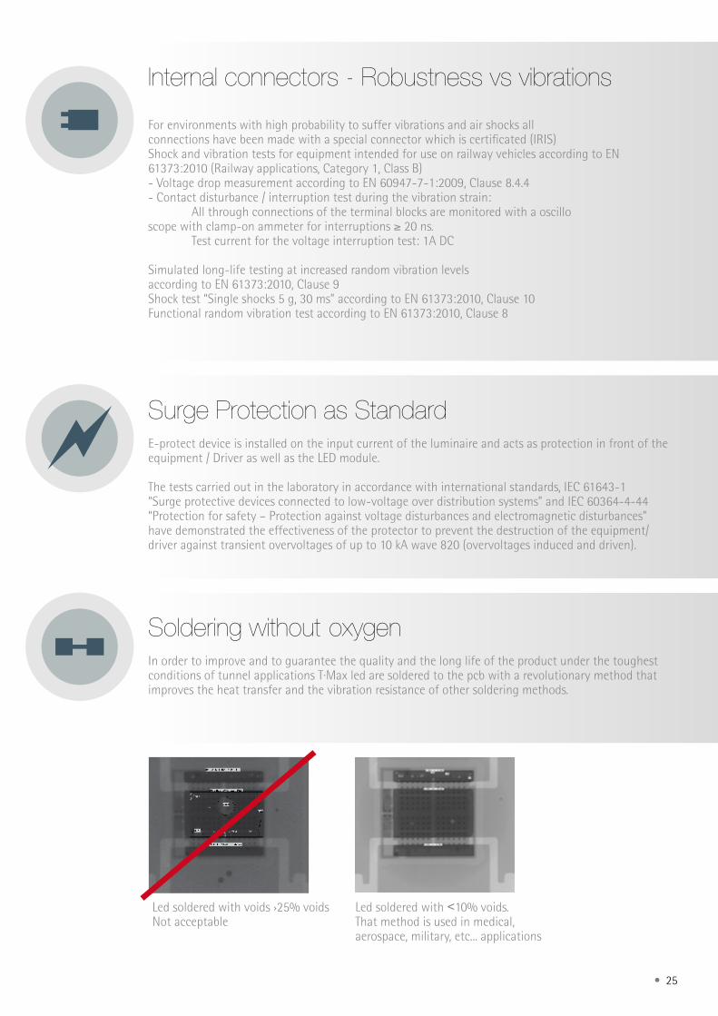
Internal connectors - Robustness vs vibrations
For environments with high probability to suffer vibrations and air shocks all connections have been made with a special connector which is certificated (IRIS)Shock and vibration tests for equipment intended for use on railway vehicles according to EN 61373:2010 (Railway applications, Category 1, Class B)- Voltage drop measurement according to EN 60947-7-1:2009, Clause 8.4.4- Contact disturbance / interruption test during the vibration strain: All through connections of the terminal blocks are monitored with a oscillo scope with clamp-on ammeter for interruptions ≥ 20 ns. Test current for the voltage interruption test: 1A DC
Simulated long-life testing at increased random vibration levelsaccording to EN 61373:2010, Clause 9Shock test “Single shocks 5 g, 30 ms” according to EN 61373:2010, Clause 10Functional random vibration test according to EN 61373:2010, Clause 8
Surge Protection as StandardE-protect device is installed on the input current of the luminaire and acts as protection in front of the equipment / Driver as well as the LED module.
The tests carried out in the laboratory in accordance with international standards, IEC 61643-1 “Surge protective devices connected to low-voltage over distribution systems” and IEC 60364-4-44 “Protection for safety – Protection against voltage disturbances and electromagnetic disturbances” have demonstrated the effectiveness of the protector to prevent the destruction of the equipment/driver against transient overvoltages of up to 10 kA wave 820 (overvoltages induced and driven).
Soldering without oxygen In order to improve and to guarantee the quality and the long life of the product under the toughest conditions of tunnel applications T·Max led are soldered to the pcb with a revolutionary method that improves the heat transfer and the vibration resistance of other soldering methods.
Led soldered with voids ›25% voidsNot acceptable
Led soldered with ˂10% voids. That method is used in medical, aerospace, military, etc... applications
26 •
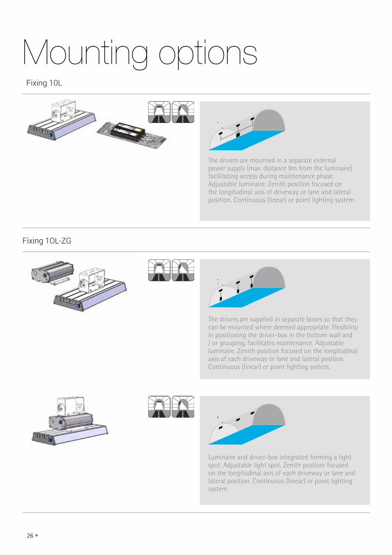
Fixing 10L
Fixing 1OL-ZG
The drivers are mounted in a separate external power supply (max. distance 9m from the luminaire) facilitating access during maintenance phase. Adjustable luminaire. Zenith position focused on the longitudinal axis of driveway or lane and lateral position. Continuous (linear) or point lighting system.
The drivers are supplied in separate boxes so that they can be mounted where deemed appropriate. Flexibility in positioning the driver-box in the bottom wall and / or grouping, facilitates maintenance. Adjustable luminaire. Zenith position focused on the longitudinal axis of each driveway or lane and lateral position. Continuous (linear) or point lighting system.
Luminaire and driver-box integrated forming a light spot. Adjustable light spot. Zenith position focused on the longitudinal axis of each driveway or lane and lateral position. Continuous (linear) or point lighting system.
Mounting options
• 27
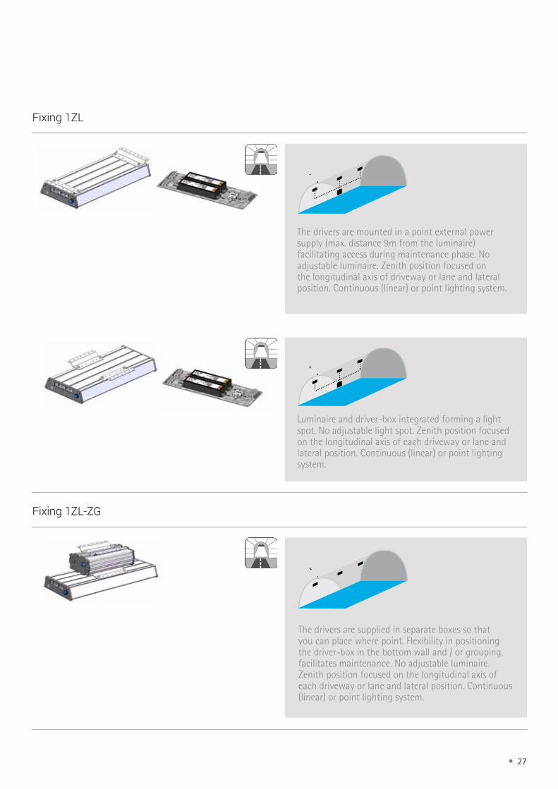
Fixing 1ZL
The drivers are mounted in a point external power supply (max. distance 9m from the luminaire) facilitating access during maintenance phase. No adjustable luminaire. Zenith position focused on the longitudinal axis of driveway or lane and lateral position. Continuous (linear) or point lighting system.
Luminaire and driver-box integrated forming a light spot. No adjustable light spot. Zenith position focused on the longitudinal axis of each driveway or lane and lateral position. Continuous (linear) or point lighting system.
Fixing 1ZL-ZG
The drivers are supplied in separate boxes so that you can place where point. Flexibility in positioning the driver-box in the bottom wall and / or grouping, facilitates maintenance. No adjustable luminaire. Zenith position focused on the longitudinal axis of each driveway or lane and lateral position. Continuous (linear) or point lighting system.
28 •
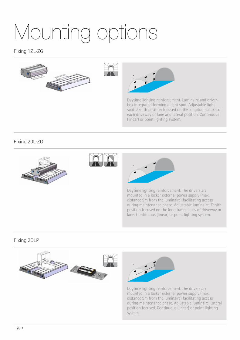
Fixing 1ZL-ZG
Fixing 20L-ZG
Fixing 2OLP
Daytime lighting reinforcement. Luminaire and driver-box integrated forming a light spot. Adjustable light spot. Zenith position focused on the longitudinal axis of each driveway or lane and lateral position. Continuous (linear) or point lighting system.
Daytime lighting reinforcement. The drivers are mounted in a locker external power supply (max. distance 9m from the luminaire) facilitating access during maintenance phase. Adjustable luminaire. Zenith position focused on the longitudinal axis of driveway or lane. Continuous (linear) or point lighting system.
Daytime lighting reinforcement. The drivers are mounted in a locker external power supply (max. distance 9m from the luminaire) facilitating access during maintenance phase. Adjustable luminaire. Lateral position focused. Continuous (linear) or point lighting system.
Mounting options
• 29
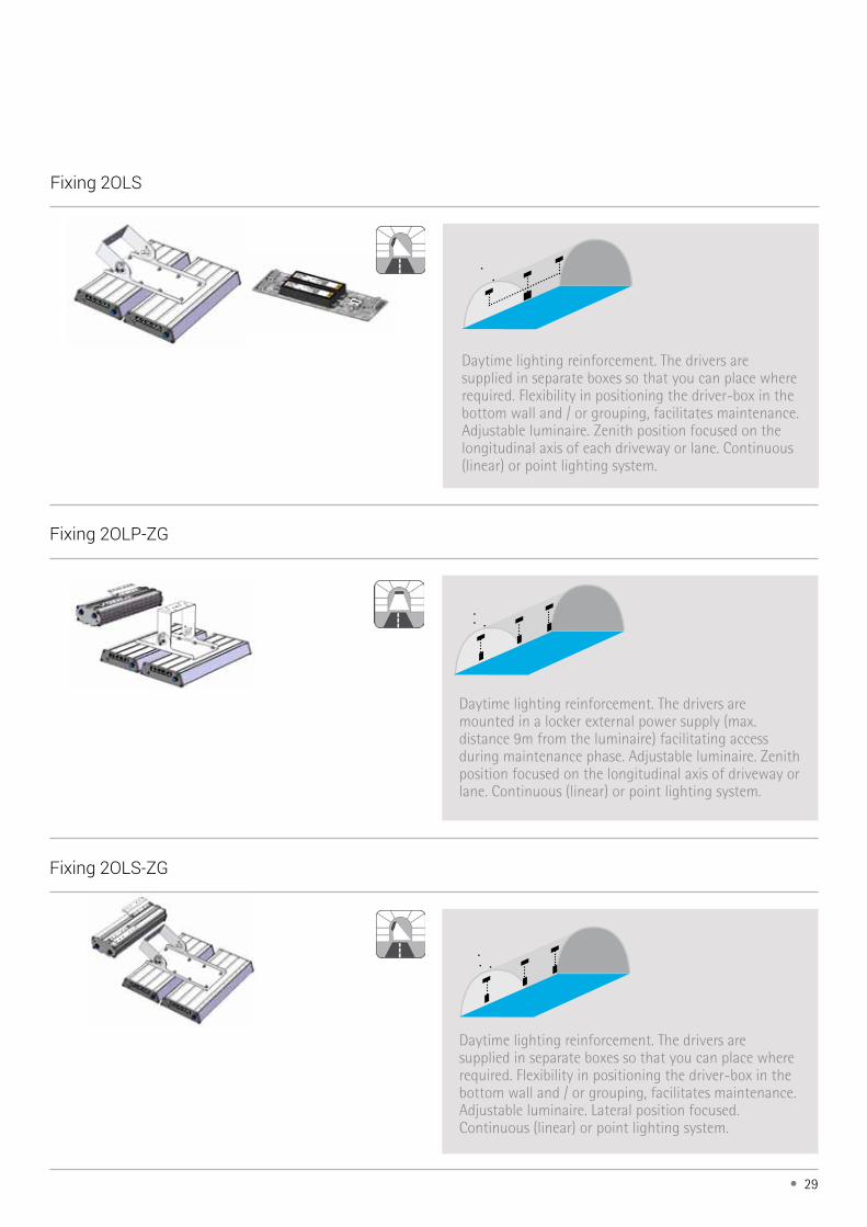
Fixing 2OLP-ZG
Fixing 2OLS-ZG
Daytime lighting reinforcement. The drivers are supplied in separate boxes so that you can place where required. Flexibility in positioning the driver-box in the bottom wall and / or grouping, facilitates maintenance. Adjustable luminaire. Lateral position focused. Continuous (linear) or point lighting system.
Fixing 2OLS
Daytime lighting reinforcement. The drivers are supplied in separate boxes so that you can place where required. Flexibility in positioning the driver-box in the bottom wall and / or grouping, facilitates maintenance. Adjustable luminaire. Zenith position focused on the longitudinal axis of each driveway or lane. Continuous (linear) or point lighting system.
Daytime lighting reinforcement. The drivers are mounted in a locker external power supply (max. distance 9m from the luminaire) facilitating access during maintenance phase. Adjustable luminaire. Zenith position focused on the longitudinal axis of driveway or lane. Continuous (linear) or point lighting system.
30 •
GTRAYGBOX
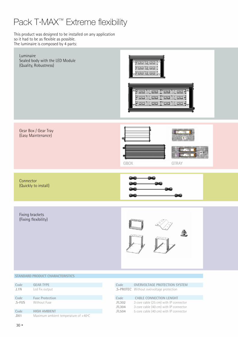
Pack T·mAX™ Extreme flexibility
LuminaireSealed body with the LED Module(Quality, Robustness)
STANDARD PRODUCT CHARACTERISTICS
Code GEAR TYPE.L1N Led Fix output
Code Fuse Protection.S-FUS Without Fuse
Code HIGH AMBIENT.D01 Maximum ambient temperature of +40ºC
Code OVERVOLTAGE PROTECTION SYSTEM.S-PROTEC Without overvoltage protection
Code CABLE CONNECTION LENGHT.FL302 3 core cable (25 cm) with IP connector.FL304 3 core cable (40 cm) with IP connector.FL504 5 core cable (40 cm) with IP connector
Gear Box / Gear Tray(Easy Maintenance)
Connector(Quickly to install)
Fixing brackets(Fixing flexibility)
This product was designed to be installed on any application so it had to be as flexible as possible. The luminaire is composed by 4 parts:
• 31
GTRAY
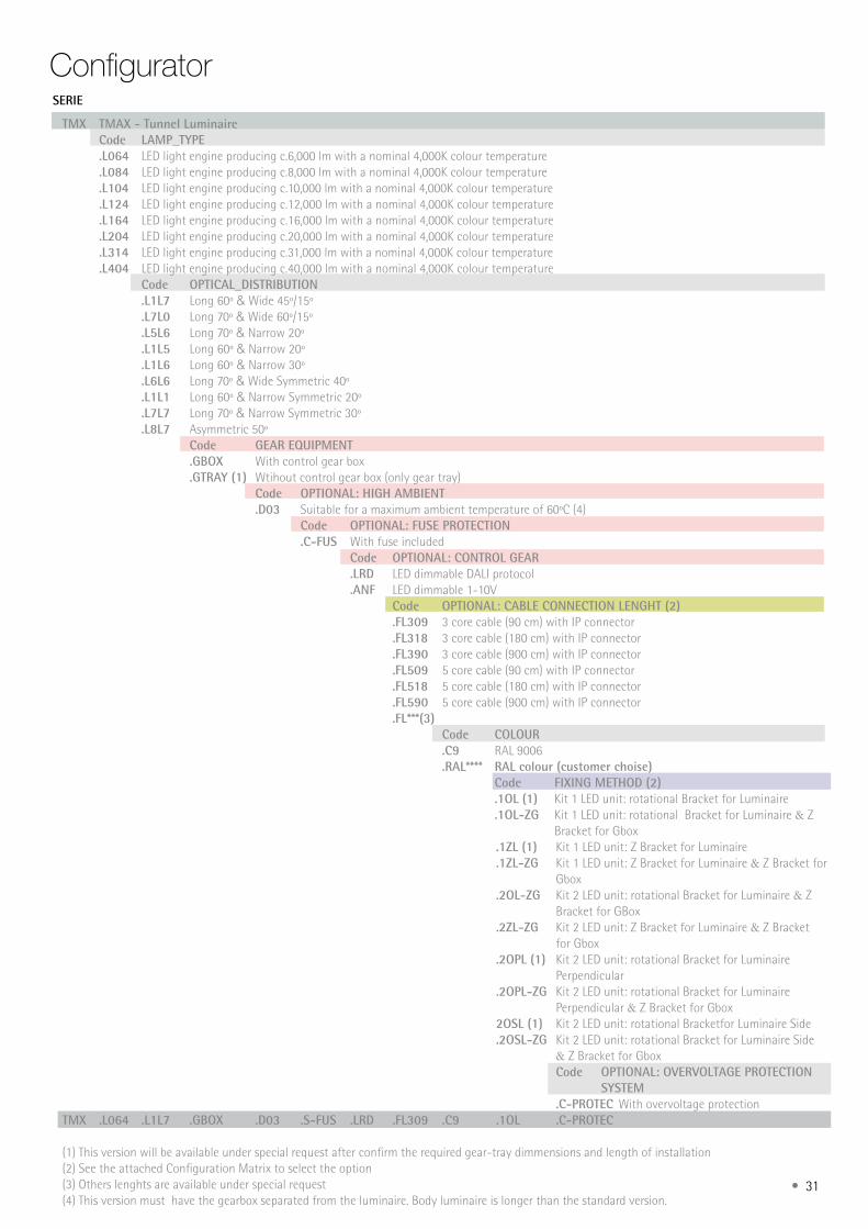
ConfiguratorSERIE
TMX TMAX - Tunnel Luminaire Code LAMP_TYPE .L064 LED light engine producing c.6,000 lm with a nominal 4,000K colour temperature .L084 LED light engine producing c.8,000 lm with a nominal 4,000K colour temperature .L104 LED light engine producing c.10,000 lm with a nominal 4,000K colour temperature .L124 LED light engine producing c.12,000 lm with a nominal 4,000K colour temperature .L164 LED light engine producing c.16,000 lm with a nominal 4,000K colour temperature .L204 LED light engine producing c.20,000 lm with a nominal 4,000K colour temperature .L314 LED light engine producing c.31,000 lm with a nominal 4,000K colour temperature .L404 LED light engine producing c.40,000 lm with a nominal 4,000K colour temperature Code OPTICAL_DISTRIBUTION .L1L7 Long 60º & Wide 45º/15º .L7L0 Long 70º & Wide 60º/15º .L5L6 Long 70º & Narrow 20º .L1L5 Long 60º & Narrow 20º .L1L6 Long 60º & Narrow 30º .L6L6 Long 70º & Wide Symmetric 40º .L1L1 Long 60º & Narrow Symmetric 20º .L7L7 Long 70º & Narrow Symmetric 30º .L8L7 Asymmetric 50º Code GEAR EQUIPMENT .GBOX With control gear box .GTRAY (1) Wtihout control gear box (only gear tray) Code OPTIONAL: HIGH AMBIENT .D03 Suitable for a maximum ambient temperature of 60ºC (4) Code OPTIONAL: FUSE PROTECTION .C-FUS With fuse included Code OPTIONAL: CONTROL GEAR .LRD LED dimmable DALI protocol .ANF LED dimmable 1-10V Code OPTIONAL: CABLE CONNECTION LENGHT (2) .FL309 3 core cable (90 cm) with IP connector .FL318 3 core cable (180 cm) with IP connector .FL390 3 core cable (900 cm) with IP connector .FL509 5 core cable (90 cm) with IP connector .FL518 5 core cable (180 cm) with IP connector .FL590 5 core cable (900 cm) with IP connector .FL***(3) Code COLOUR .C9 RAL 9006 .RAL**** RAL colour (customer choise) Code FIXING METHOD (2) .1OL (1) Kit 1 LED unit: rotational Bracket for Luminaire .1OL-ZG Kit 1 LED unit: rotational Bracket for Luminaire & Z Bracket for Gbox .1ZL (1) Kit 1 LED unit: Z Bracket for Luminaire .1ZL-ZG Kit 1 LED unit: Z Bracket for Luminaire & Z Bracket for Gbox .2OL-ZG Kit 2 LED unit: rotational Bracket for Luminaire & Z Bracket for GBox .2ZL-ZG Kit 2 LED unit: Z Bracket for Luminaire & Z Bracket for Gbox .2OPL (1) Kit 2 LED unit: rotational Bracket for Luminaire Perpendicular .2OPL-ZG Kit 2 LED unit: rotational Bracket for Luminaire Perpendicular & Z Bracket for Gbox 2OSL (1) Kit 2 LED unit: rotational Bracketfor Luminaire Side .2OSL-ZG Kit 2 LED unit: rotational Bracket for Luminaire Side & Z Bracket for Gbox Code OPTIONAL: OVERVOLTAGE PROTECTION SYSTEM .C-PROTEC With overvoltage protectionTMX .L064 .L1L7 .GBOX .D03 .S-FUS .LRD .FL309 .C9 .1OL .C-PROTEC
(1) This version will be available under special request after confirm the required gear-tray dimmensions and length of installation(2) See the attached Configuration Matrix to select the option(3) Others lenghts are available under special request(4) This version must have the gearbox separated from the luminaire. Body luminaire is longer than the standard version.
32 •
GEARBOX SEPARATED FROM THE LUMINAIRE
.L064 .L084 .L104 .L164 .L204 .L314 .L404
.1OL-ZG .FL309 .FL318.FL390
.FL309
.FL318
.FL390
.FL509
.FL518
.FL590
.1ZL-ZG .FL309 .FL318.FL390
.FL309
.FL318
.FL390
.FL509
.FL518
.FL590
.2OPL-ZG .FL309 .FL318.FL390
.FL509
.FL518
.FL590
.2OSL-ZG .FL309 .FL318.FL390
.FL509
.FL518
.FL590
GEARBOX FIXED ON THE LUMINAIRE
.L064 .L084 .L104 .L124
.L164 .L204 .L314 .L404
.1OL-ZG .FL302 .FL302 .FL504
.1ZL-ZG .FL302 .FL302 .FL504
.2OL-ZG .FL304 .FL504
.2ZL-ZG .FL304 .FL504
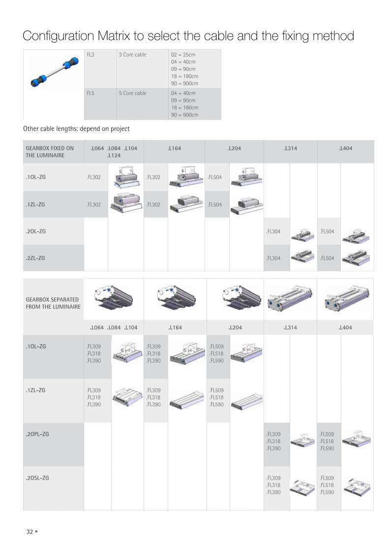
FL3 3 Core cable 02 = 25cm04 = 40cm09 = 90cm18 = 180cm 90 = 900cm
FL5 5 Core cable 04 = 40cm09 = 90cm18 = 180cm90 = 900cm
Configuration matrix to select the cable and the fixing method
Other cable lengths: depend on project
• 33
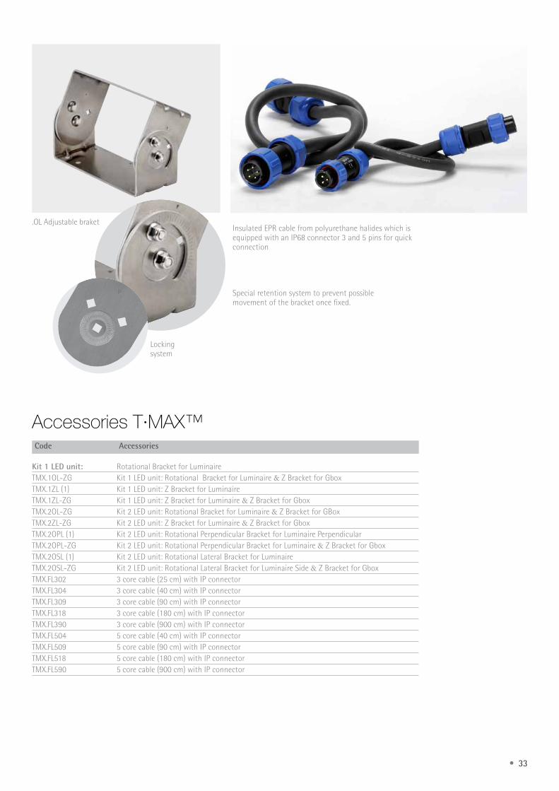
Accessories T·mAX™
Insulated EPR cable from polyurethane halides which is equipped with an IP68 connector 3 and 5 pins for quick connection
.OL Adjustable braket
Special retention system to prevent possible movement of the bracket once fixed.
Locking system
Code Accessories
Kit 1 LED unit: Rotational Bracket for LuminaireTMX.1OL-ZG Kit 1 LED unit: Rotational Bracket for Luminaire & Z Bracket for GboxTMX.1ZL (1) Kit 1 LED unit: Z Bracket for LuminaireTMX.1ZL-ZG Kit 1 LED unit: Z Bracket for Luminaire & Z Bracket for GboxTMX.2OL-ZG Kit 2 LED unit: Rotational Bracket for Luminaire & Z Bracket for GBoxTMX.2ZL-ZG Kit 2 LED unit: Z Bracket for Luminaire & Z Bracket for GboxTMX.2OPL (1) Kit 2 LED unit: Rotational Perpendicular Bracket for Luminaire PerpendicularTMX.2OPL-ZG Kit 2 LED unit: Rotational Perpendicular Bracket for Luminaire & Z Bracket for GboxTMX.2OSL (1) Kit 2 LED unit: Rotational Lateral Bracket for LuminaireTMX.2OSL-ZG Kit 2 LED unit: Rotational Lateral Bracket for Luminaire Side & Z Bracket for Gbox TMX.FL302 3 core cable (25 cm) with IP connectorTMX.FL304 3 core cable (40 cm) with IP connectorTMX.FL309 3 core cable (90 cm) with IP connectorTMX.FL318 3 core cable (180 cm) with IP connectorTMX.FL390 3 core cable (900 cm) with IP connectorTMX.FL504 5 core cable (40 cm) with IP connectorTMX.FL509 5 core cable (90 cm) with IP connectorTMX.FL518 5 core cable (180 cm) with IP connectorTMX.FL590 5 core cable (900 cm) with IP connector
34 •

• 35
Dimensionsdimensions in mm
633 570
450
161
90
294
213110
14010060
Ø17
60
Ø11
72
.L164/.L204.GTRAY.1ZL
.L314/.L404.GTRAY.20SL
150mm
150mm
633 278
204
100
710 MAX.
59,5
72
16060
Ø11

36 •
.L314/.L404.GTRAY.20PL
.L314/.L404.GBOX.2ZL-ZG
633 570
400
161
90
294
213200
140
100
60
Ø17
60
Ø11
72
633
204
221
UP
620 máx.
570
16060
59,5
Ø11
72

• 37
UP332
83
278
90213
633140100
60
Ø17
60
Ø11
72
.L064/.L084/.L104/.L124.GBOX.1ZL-ZG
.L164/.L204.GBOX.1OL-ZG
204
UP
221
390 278
420 MÁX.
18060
59,5 Ø11
72

38 •
83
90
UP
332
390 278140100
60
Ø17
60
Ø11
213
72
633
332 UP
570
83
90
140100
60
Ø17
60
Ø11
213
72
.L314/.L404.GBOX.2OL-ZG
.L064/.L084/.L104/.L124.GBOX.1OL-ZG

• 39
83
90
390278140
100
60
Ø17
60
Ø11
213
72
210
83
90
278
72
633
140100
60
Ø17
60
Ø11
213
210
.L064/.L084/.L104/.L124.GTRAY.1OL
.L164/.L204/.GTRAY.1OL
C. & G. CARANDINI, S.A. Carrerada – Verneda E-08107 Martorelles Barcelona (España)
Tel.: (+34) 93 317 40 08 Fax: (+34) 93 317 18 90
To obtain more information, download technical specifications and instruction sheets, etc, visit our website
www.carandini.com C. & G. Carandini, S.A. reserves the right to modify its products without prior notice.
C. & G. Carandini, S.A. 2015©FL-0416-217
Mor
e lig
ht le
ss e
nerg
y