Embed Size (px)
Citation preview
Journal of
Carbon Research C
Review
Carbons Formed in Methane Thermal and ThermocatalyticDecomposition Processes: Properties and Applications
Emmi Välimäki 1, Lasse Yli-Varo 1, Henrik Romar 2 and Ulla Lassi 1,*
�����������������
Citation: Välimäki, E.; Yli-Varo, L.;
Romar, H.; Lassi, U. Carbons Formed
in Methane Thermal and
Thermocatalytic Decomposition
Processes: Properties and
Applications. C 2021, 7, 50.
https://doi.org/10.3390/c7030050
Academic Editor: Gil Goncalves
Received: 4 June 2021
Accepted: 23 June 2021
Published: 25 June 2021
Publisher’s Note: MDPI stays neutral
with regard to jurisdictional claims in
published maps and institutional affil-
iations.
Copyright: © 2021 by the authors.
Licensee MDPI, Basel, Switzerland.
This article is an open access article
distributed under the terms and
conditions of the Creative Commons
Attribution (CC BY) license (https://
creativecommons.org/licenses/by/
4.0/).
1 Research Unit of Sustainable Chemistry, University of Oulu, P.O. Box 4300, FI-90014 Oulu, Finland;[email protected] (E.V.); [email protected] (L.Y.-V.)
2 Hycamite TCD Technologies Ltd., FI-67100 Kokkola, Finland; [email protected]* Correspondence: [email protected]; Tel.: +358-400294090
Abstract: The hydrogen economy will play a key role in future energy systems. Several thermaland catalytic methods for hydrogen production have been presented. In this review, methanethermocatalytic and thermal decomposition into hydrogen gas and solid carbon are considered.These processes, known as the thermal decomposition of methane (TDM) and thermocatalyticdecomposition (TCD) of methane, respectively, appear to have the greatest potential for hydrogenproduction. In particular, the focus is on the different types and properties of carbons formed duringthe decomposition processes. The applications for carbons are also investigated.
Keywords: methane; hydrogen; carbon; catalytic decomposition; wet decomposition; dry decompo-sition; hydrogen economy
1. Introduction
The hydrogen economy has attracted a significant amount of interest since the Euro-pean Union (EU) revealed a new strategy to reach carbon neutrality by 2050. The increasedinterest in hydrogen is due to its potential as a fuel and as an energy carrier, its capabilityfor energy storage, and its use as a carbon-neutral feedstock without carbon dioxide (CO2)emissions. At present, hydrogen is mainly produced from fossil fuels, and hydrogenproduction in the EU releases about 70 to 100 million tons of CO2 per annum [1]. If ameans of production can be developed that does not release CO2, hydrogen will play a keyrole in creating a climate-neutral Europe. One major issue to be resolved is how to makethe CO2-free hydrogen production process cost competitive compared with fossil-basedhydrogen processes.
Production of hydrogen from methane is considered to be the best option compared tothe use of other hydrocarbons. This is due to the fact that methane is abundant, and can beeasily transported and stored when needed. Methane also has a high hydrogen to carbonratio of 4:1 [2]. In addition to methane’s significant importance in hydrogen production,methane is also used in power generation and methanol production [3]. Hydrogen can beproduced from methane in several ways. In this article, we present the most importantproduction processes and note some advantages and disadvantages for each process.At present, the most commonly used processes for hydrogen production from methane,and especially renewable biomethane, are steam methane reforming (SMR), dry methanereforming (DMR), and partial oxidation (PO) [4]. None of these processes are CO2-neutral;CO2 is emitted, or a separate carbon capture process is required after the main process. Theaddition of the extra step increases the price of the hydrogen produced. In the thermaldecomposition of methane (TDM) and thermocatalytic decomposition (TCD) of methane,no oxygen is involved in the reaction, and solid carbon is formed. Compared to othermethane conversion methods in which carbon is released to the atmosphere, TDM andTCD processes create carbon capture and therefore have a significant effect on carbon’sneutrality and footprint. Most of the recently published papers consider the formation
C 2021, 7, 50. https://doi.org/10.3390/c7030050 https://www.mdpi.com/journal/carbon

C 2021, 7, 50 2 of 16
and use of the hydrogen formed in the decomposition of methane, whereas the carbonsformed in the process are considered as less important. However, the carbon formed hasits own markets and possible applications, such as usage in water purification and energystorage applications. A full use of the carbons formed in the TDM and TCD processesin potential applications would result in increased value, and increase the profitability ofthese decomposition processes and the overall hydrogen economy. In this paper, we focuson the carbon produced from the TCD process, its properties, and possible applications. Wealso briefly examine other methane conversion processes to highlight the benefits of TCD.
2. Production Methods for Hydrogen and Carbon from Methane
Various methods exist for producing hydrogen from methane, such as SMR, DRM, PO,TDM, and TCD. The latter two processes are considered more environmentally friendlybecause they do not create CO2 or carbon monoxide (CO) emissions [5]. One importantdifference between these methods is the end use of the carbon. In the first three reactions(SMR, DRM, and PO), carbon is emitted as CO2 or CO, whereas in TDM and TCD, soliddeposits of carbon are formed. Instead of producing CO2 gas, TDM/TCD processesproduce carbon as a potentially valuable solid. The reactions for these processes andcorresponding reaction enthalpies are presented in Table 1.
Table 1. Chemical reactions for hydrogen production from methane and corresponding reaction enthalpies. In the firstthree reactions (SMR, DRM, and PO), carbon is emitted as CO2 or CO, whereas in TDM and TCD, solid deposits of carbonare formed.
Production Method Chemical Equation Reaction Enthalpies Equation Number
Steam methane reforming (SMR) CH4 + H2O→ CO + 3H2 ∆H298K = 206 kJ/mol (1)Water gas shift reaction (WGS) CO + H2O→ CO2 + H2 ∆H298K = −41 kJ/mol (2)
Dry reforming of methane (DRM) CH4 + CO2 → 2CO + 2H2 ∆H298K = 247 kJ/mol (3)Partial oxidation (PO) CH4 + 0.5O2 → CO + 2H2 ∆H298K = −23 kJ/mol (4)
Thermal decomposition of methane (TDM)Thermocatalytic decomposition of methane (TCD) CH4 → C + 2H2 ∆H298K = 75 kJ/mol (5)
SMR (Equation (1)) is one of the most mature processes in hydrogen production,starting from methane. The SMR reaction is endothermic and therefore has a high energyconsumption. However, the SMR process has some severe drawbacks and challenges thatshould be considered. The process is usually carried out at relatively high temperatures,973–1273 K, and at reaction pressures ranging from 0.3 to 2.5 MPa [6]. Another drawbackis that SMR generates large amounts of CO2 [5]. According to Soltani et al. [7], SMRgenerates approximately 7 kg of CO2 to every 1 kg of H2 produced. Although SMR is oneof the least expensive processes in large-scale hydrogen production [6], a harsh reactionenvironment can create corrosion risks, especially if sulfur is present, a condition thatcan appear if the gas is not adequately purified [6,8]. In SMR, the catalyst plays a keyrole in the process. The use of a catalyst increases the yield of hydrogen and lowers thetemperature, and no pressure is used. The cost of the catalysts, possible toxicity of theactive metals used, and availability and deactivation of the catalyst by the formation ofcoke, should be considered [4,9]. To gain additional hydrogen from the SMR process,the water gas shift (WGS) reaction (Equation (2)) is usually introduced. In the WGS,CO is transformed into CO2 and hydrogen, usually after the SMR reaction [9]. WGSis an exothermic reaction that is normally undertaken in two reactors: one with a hightemperature in which thermal equilibrium is reached and one with a lower temperaturein which the catalyst provides higher conversions; that latter process is much slower. Inaddition to SMR, WGS is also affected by process parameters, and therefore the variationin performance can vary. Another drawback of WGS is that the activity of the reactiondecreases at lower temperatures, which creates additional carbon. This can be an issue,especially in fuel cell applications where lower CO is required.
C 2021, 7, 50 3 of 16
Another well-known hydrogen production process is dry reforming (Equation (3)).One of the main benefits of DRM is that it consumes methane and CO2 to create hydrogen,and it is also cheaper when compared with SMR and PO [6]. However, like SMR, itproduces CO [9]. The operating temperature ranges from 923 to 1123 K, and the pressure isnormally 0.1 MPa [6].
PO is an exothermic reaction (Equation (4)) carried out at a pressure of 10 MPa and atemperature range of 1223 to 1373 K [4,10]. Due to the exothermic reaction, the process isdifficult to control because of the induced hotspots on the catalyst [8]. If air is used as anoxygen source, nitrogen separation is required from the gas prior to the reaction, a processthat increases operational costs. It is therefore recommended to use pure oxygen and/orseparate the oxygen from the air [10]. Oxygen separation from air makes the processcostly [4]. The benefits of the process are short residence time, high conversion rates, highselectivity of syngas, good economic conversion, and compactness [8,11–13].
Thermal decomposition of methane has two alternating routes (Equation (5)): catalytic(TCD) and non-catalytic (TDM) [14]. The latter has been used for several decades for theproduction of carbon black. Methane is one of the most stable hydrocarbons due to its verystrong carbon–hydrogen bond and high molecular structure symmetry [15]. In TDM, thereaction temperature is relatively high, and may reach 1473 K for a reasonable hydrogenyield [14,15]. By using a catalyst, this temperature can be significantly lowered, and thecatalyst can influence the formed carbon. Both processes are CO2-free, and therefore theyhave gained increased interest. In this paper, however, we focus on the TCD catalyticreaction, because the carbon formed can have different morphologies and greater valuethan with the use of TDM. TCD has remained in the laboratory phase mostly because ofthe deactivation of the catalyst, the possibility of CO2 formation during reactivation of thecatalyst, and the unreacted methane in hydrogen [15]. Several catalysts have been testedfor the reaction, and these can be divided into two separate groups: noble metals andtransition metals, such as nickel and iron; and carbon-based materials, such as activatedcarbon [16]. Metal catalysts can be supported by high surface area materials, such as Al2O3and SiO2, and carbon can be doped with some metals. Different catalysts have varyingeffects on the process, and so it is important to select the best catalyst to produce carbon.The effect of catalysts is discussed later in this paper. Economic and environmental issuesshould also be considered.
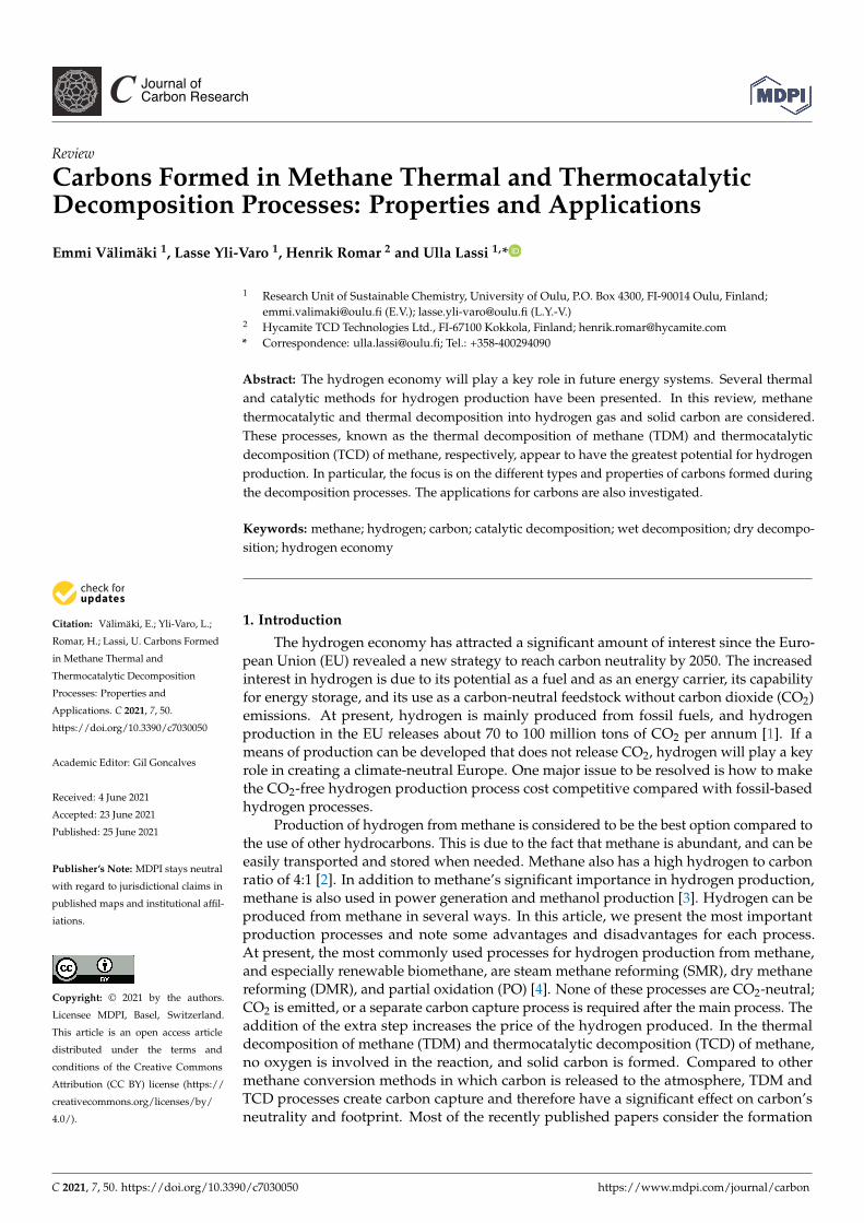
In the TCD process, the methane molecules decompose on the surface of the catalyticmetals, and in the crevices or cracks of the catalyst. The reaction generates hydrogenmolecules and carbon atoms. Carbon diffuses to the metal and accumulates to form carbondeposits [17,18]. In TCD, amorphous, graphitic, and carbon nanotube (CNT) morphologiesof carbon can be found, and the process parameters affect the morphology of the carbon.The reaction temperature is above 1473 K, and the carbon formed is mainly amorphous [16].The CNTs’ growth mechanism can be divided into two types, tip growth and base growth,in which one or the other is active, depending on the interaction between catalyst metaland support weakness. Weak interaction leads to tip growth, in which the catalyst particleis lifted by the growing CNT. Strong supports lead to base growth, in which the growthmechanism proceeds through an open tip. Regardless of the manner in which the carbongrows on the catalyst, one of the main problems to be resolved is the separation of thecarbon and catalyst used without generating any CO2 emissions [19]. The size of thecatalyst particle can affect the growth of the carbon in TCD process. This is schematicallyshown in Figure 1, in which the possible effect of large and small nickel catalyst particleson the growth of carbon is shown. Large nickel particles induce more tip growth of carbon,whereas, in the case of small nickel particles, carbon grows on the catalyst particle andencapsulates it.
C 2021, 7, 50 4 of 16C 2021, 7, x FOR PEER REVIEW 4 of 17
Figure 1. Possible mechanisms of carbon growth in the presence of large and small nickel particles
[18]. Large nickel particles induce tip growth of carbon, whereas, in the case of small nickel particles,
carbon grows on the catalyst particle and encapsulates it.
3. Carbon Morphologies
Carbon is a polymorphic material; it can exist in more than one form, such as dia-
mond, graphite, and fullerene (also known as carbon nano-onions (CNOs) and CNTs). Its
morphologies are shown in Figure 2. In addition, the level of crystallinity varies; carbon
can have amorphous, turbostratic, and graphitic crystallinity [20]. Graphite has a crystal
structure that is composed of carbon atoms hexagonally arranged in layers. Each carbon
atom has a strong covalent bond among three neighboring atoms, and the fourth electron
can form a weak bond between layers, which allows these layers to be separated. These
increase, for example, the lubricant properties of graphite. In addition, the hexagonal
sheets have relatively high electrical conductivity.
Figure 2. Structures of various carbon morphologies: (a) amorphous carbon, (b) diamond, (c) graph-
ite, (d) fullerene, (e) carbon nanotube (CNT), and (f) graphene [21]. Adapted with permission from
[21]. Springer Nature, 2011.
The structure, texture, and morphologies of the carbons formed in the TCD reaction
depend on the reaction conditions, such as pressure, temperature, catalysts, and gas phase
composition. These properties make them suitable for many applications. The properties
that affect applicability, and are thus of common interest, are surface area, pore volume,
Figure 1. Possible mechanisms of carbon growth in the presence of large and small nickel parti-cles [18]. Large nickel particles induce tip growth of carbon, whereas, in the case of small nickelparticles, carbon grows on the catalyst particle and encapsulates it.
3. Carbon Morphologies
Carbon is a polymorphic material; it can exist in more than one form, such as dia-mond, graphite, and fullerene (also known as carbon nano-onions (CNOs) and CNTs). Itsmorphologies are shown in Figure 2. In addition, the level of crystallinity varies; carboncan have amorphous, turbostratic, and graphitic crystallinity [20]. Graphite has a crystalstructure that is composed of carbon atoms hexagonally arranged in layers. Each carbonatom has a strong covalent bond among three neighboring atoms, and the fourth electroncan form a weak bond between layers, which allows these layers to be separated. Theseincrease, for example, the lubricant properties of graphite. In addition, the hexagonalsheets have relatively high electrical conductivity.
C 2021, 7, x FOR PEER REVIEW 4 of 17
Figure 1. Possible mechanisms of carbon growth in the presence of large and small nickel particles
[18]. Large nickel particles induce tip growth of carbon, whereas, in the case of small nickel particles,
carbon grows on the catalyst particle and encapsulates it.
3. Carbon Morphologies
Carbon is a polymorphic material; it can exist in more than one form, such as dia-
mond, graphite, and fullerene (also known as carbon nano-onions (CNOs) and CNTs). Its
morphologies are shown in Figure 2. In addition, the level of crystallinity varies; carbon
can have amorphous, turbostratic, and graphitic crystallinity [20]. Graphite has a crystal
structure that is composed of carbon atoms hexagonally arranged in layers. Each carbon
atom has a strong covalent bond among three neighboring atoms, and the fourth electron
can form a weak bond between layers, which allows these layers to be separated. These
increase, for example, the lubricant properties of graphite. In addition, the hexagonal
sheets have relatively high electrical conductivity.
Figure 2. Structures of various carbon morphologies: (a) amorphous carbon, (b) diamond, (c) graph-
ite, (d) fullerene, (e) carbon nanotube (CNT), and (f) graphene [21]. Adapted with permission from
[21]. Springer Nature, 2011.
The structure, texture, and morphologies of the carbons formed in the TCD reaction
depend on the reaction conditions, such as pressure, temperature, catalysts, and gas phase
composition. These properties make them suitable for many applications. The properties
that affect applicability, and are thus of common interest, are surface area, pore volume,
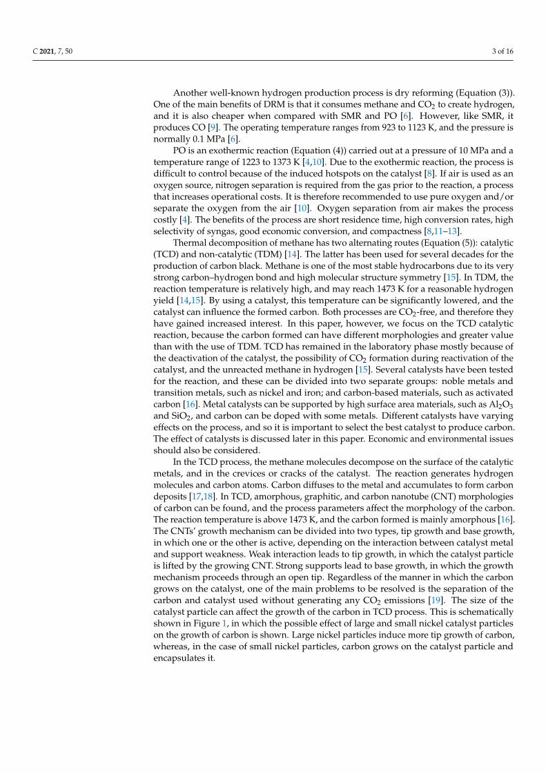
Figure 2. Structures of various carbon morphologies: (a) amorphous carbon, (b) diamond,(c) graphite, (d) fullerene, (e) carbon nanotube (CNT), and (f) graphene [21]. Adapted with permissionfrom [21]. Springer Nature, 2011.
The structure, texture, and morphologies of the carbons formed in the TCD reactiondepend on the reaction conditions, such as pressure, temperature, catalysts, and gasphase composition. These properties make them suitable for many applications. Theproperties that affect applicability, and are thus of common interest, are surface area, porevolume, pore size, porosity, and surface chemistry, in addition to the morphology [22].Transmission electron microscopy (TEM) and scanning electron microscopy (SEM) are usedto study the length, thickness, morphology, impurities, and topography of carbon deposits.Thermogravimetric analysis (TGA) is used to quantify the amount of the deposits and the

C 2021, 7, 50 5 of 16
thermal stability of the specimen. Specific surface area is measured according to the theoryof Brunauer–Emmett–Teller, commonly called BET analysis. X-ray diffraction (XRD) isused to create diffractograms of the deposits, and the crystallinity, phase structure, andpurity of the specimen can be obtained from XRD. Figure 3 shows XRD patterns for carbonsproduced by the TCD process using three different nickel catalysts. XRD peaks indicatethe crystal structure of materials. In Figure 3, the pink circle indicates carbon morphology,which, in this case, is graphite for all produced carbons. Raman spectra can also be used todetermine purity, crystallinity, and degree of structural disorder, for example, the defectsand tube alignment of the CNT [23–26].
C 2021, 7, x FOR PEER REVIEW 5 of 17
pore size, porosity, and surface chemistry, in addition to the morphology [22]. Transmis-
sion electron microscopy (TEM) and scanning electron microscopy (SEM) are used to
study the length, thickness, morphology, impurities, and topography of carbon deposits.
Thermogravimetric analysis (TGA) is used to quantify the amount of the deposits and the
thermal stability of the specimen. Specific surface area is measured according to the theory
of Brunauer–Emmett–Teller, commonly called BET analysis. X-ray diffraction (XRD) is
used to create diffractograms of the deposits, and the crystallinity, phase structure, and
purity of the specimen can be obtained from XRD. Figure 3 shows XRD patterns for car-
bons produced by the TCD process using three different nickel catalysts. XRD peaks indi-
cate the crystal structure of materials. In Figure 3, the pink circle indicates carbon mor-
phology, which, in this case, is graphite for all produced carbons. Raman spectra can also
be used to determine purity, crystallinity, and degree of structural disorder, for example,
the defects and tube alignment of the CNT [23–26].
Figure 3. XRD patterns for carbon materials produced by the TCD process over reduced (a) Ni/Z-
25, (b) Ni/Z-400, and (c) Ni/AS catalysts [27]. In all cases, a graphite-like carbon crystal structure is
seen. Adapted with permission from [27]. Elsevier, 2016.
One of the most studied components in the TCD process to produce carbon are CNTs.
These are rolled graphene layers that can form single- or multiwalled tubes, which can
differ in thickness, diameter, and layer amount [28]. Typical properties of CNTs are high
electrical conductivity and high tensile strength. Physically and chemically, CNTs are sta-
ble [29]. They are used in polymers, wastewater/pollution treatment, conductive
paints/coatings, biosensors, electronics, energy storage, and environmental applications
[29,30]. A major application is to reinforce polymers to improve thermal, electrical, and
mechanical properties, and interest in using CNTs in the production of lithium-ion bat-
teries has increased, because they improve the efficiency of the batteries [30].
Carbon fibers (CNFs) are polycrystalline; they have both graphitic and amorphous
regions. The amorphous regions lack hexagonal carbon networks that are characteristic of
graphite [20]. CNFs have high tensile strength and stiffness, and low density and coeffi-
cient of thermal expansion. They are used in the aerospace, vehicle manufacturing, en-
ergy, sports equipment, and chemical and textile industries, and as a reinforcement in
composite materials [30].
Figure 3. XRD patterns for carbon materials produced by the TCD process over reduced (a) Ni/Z-25,(b) Ni/Z-400, and (c) Ni/AS catalysts [27]. In all cases, a graphite-like carbon crystal structure is seen.Adapted with permission from [27]. Elsevier, 2016.
One of the most studied components in the TCD process to produce carbon are CNTs.These are rolled graphene layers that can form single- or multiwalled tubes, which can differin thickness, diameter, and layer amount [28]. Typical properties of CNTs are high electricalconductivity and high tensile strength. Physically and chemically, CNTs are stable [29].They are used in polymers, wastewater/pollution treatment, conductive paints/coatings,biosensors, electronics, energy storage, and environmental applications [29,30]. A majorapplication is to reinforce polymers to improve thermal, electrical, and mechanical proper-ties, and interest in using CNTs in the production of lithium-ion batteries has increased,because they improve the efficiency of the batteries [30].
Carbon fibers (CNFs) are polycrystalline; they have both graphitic and amorphousregions. The amorphous regions lack hexagonal carbon networks that are characteristicof graphite [20]. CNFs have high tensile strength and stiffness, and low density andcoefficient of thermal expansion. They are used in the aerospace, vehicle manufacturing,energy, sports equipment, and chemical and textile industries, and as a reinforcement incomposite materials [30].
Carbon fullerenes resemble the shape of a sphere [20]. One form of carbon fullerenes iscommonly referred to as a CNO, which are multiwalled fullerenes [31]. Carbon fullereneshave not been found in the TCD reaction, but CNOs have. Fullerenes have shown signifi-cant promise in several applications, such as solid lubrication, electromagnetic shielding,fuel cells, heterogeneous catalysis, energy storage, electro-optical devices, and superca-pacitors [32]. CNOs can have a crucial effect on the TCD process. According to theinvestigations of Zhou et al. [19], formed CNOs encapsulated the catalyst and, therefore,the catalyst was deactivated.
C 2021, 7, 50 6 of 16
4. Process Parameters Affecting the Properties of Carbon in TDM and TCD Processes
As mentioned previously, the TCD of methane produces hydrogen and carbon. Theyields and carbon morphology are dependent on various process parameters, such asthe kind of catalyst used, size of the catalyst’s metal particle, promoter material, reac-tion temperature, pressure, and gas hourly space velocity (GHSV) [33–40]. According toLi et al. [40], the carbon yield is mostly affected by the particle size of the metallic catalyst,and also affects the catalytic life [41]. It has also been mentioned that the carbon mor-phology affects the efficiency of thermocatalytic decomposition when carbon is used as acatalyst support [35]. The factors affecting catalytic life have been widely studied, and it isvaluable to understand how this occurs and the kind of carbon that is formed. In the TDMprocess, temperatures are higher than those in TCD, and are typically above 1200 ◦C. Themain products in TDM are carbon black graphite-like carbon and coke [42].
4.1. Effect of Catalyst and Promoters on the Carbon Amount and Quality
Guil-Lopez et al. [43] compared metal and carbon catalysts in the TCD process, andtheir differences in terms of hydrogen production and carbon morphology (size and shape).They used Ni and Fe metal catalysts with different supports and six different carboncatalysts, which included carbon black, activated carbon, graphene, and CNTs. Interest incarbon catalysts has risen due to their lower cost, higher temperatures, which affect themethane conversion rate, and the possibility that there is no need to separate catalyst carbonand produced carbon [16] According to the results of a study by Guil-Lopez et al. [43],metal catalysts are more prone to produce CNTs when carbon catalysts produced moregraphene-like carbon. Carbon catalyst activity depends on the chemical structure, such asdefects, BET surface area, and pore volume. By designing and preparing carbon materialswith specific pore systems, catalytic activity and stability can be improved [22]. Whencomparing amorphous carbon with more ordered carbon, Muradov found that amorphouscarbon had more catalytic activity than ordered carbon [44].
Nickel-based catalysts have gained interest due to their capability to produce high-value carbon, such as CNTs and CNFs, and because of their high catalytic activity [45]. Thedrawbacks of using Ni catalysts are their sensitivity to the operation temperature and quickdeactivation [46]. Torres et al. [36] studied the effect of numerous catalysts on TCD andfound that the Cu-doped Ni/Al2O3 catalyst had a higher yield in carbon formation and alonger activity time at a temperature range of 823–873 K. In addition, the bimetallic Ni-Cucatalyst produced shorter carbon filaments, and the diameter of the filament was moreconstant compared with the metallic catalyst. Saraswat and Pant [38] studied Cu/Zn metalsas promoters with a Ni aluminosilicate catalyst in TCD. Their results indicate that the yieldand type of carbon depends on the added amount of Cu and Zn promoters, in addition tothe process temperature. Saraswat et al. [47] studied the effect of the process parameters onthe methane conversion and carbon amount. First, they studied the effect of temperature onyield. They examined the process at five different temperatures, ranging from 823 to 1023 Kin 323 degree steps. The best methane conversion rate was found at 1023 K. In furtherstudies, they used this temperature. The highest carbon yields were at 1023 K and with thecatalyst combination of 50% Ni–10% Cu with the support of SiO2. The carbon yield usingthis 50% Ni–10% Cu/SiO2 catalyst was 710%. The second highest carbon yield (610%)was obtained using the 50% Ni–5% Cu catalyst. Table 2 presents the results of Saraswatet al. [46], indicating the catalyst and support used, temperature and GHSV of the TCDprocess, and the produced carbon amounts and yields. Bai et al. [33] tested active CNFsas catalysts that were loaded with Ni. They stated that the surface structure and texturalproperties of the CNFs can affect the stability and activity of the catalyst. Their producedcarbon was consistent in diameter and relatively long. Nickel particle size has been provento have a significant effect on carbon formation and catalyst deactivation [18,39]. Smallermetal particle sizes increase the deactivation rate of the catalysts. This can be explained bythe fact that CNTs are prone to form on a large particle when a smaller size is encapsulatedby carbon [35].

C 2021, 7, 50 7 of 16
Table 2. Different Ni and Ni/Cu catalysts on SiO2 support and their effect on the carbon amounts and yields in the TCDreaction (at 1023 K and with GHSV of 1800).
Catalyst Support OperatingTemperature [K]
GHSV[mL/gcat h] gC/gCH4 Fed Carbon Yield % Source
50 wt% Ni SiO2 1023 1800 0.504 600%
[47]50 wt% Ni/5 wt% Cu SiO2 1023 1800 0.531 610%50 wt% Ni/10 wt% Cu SiO2 1023 1800 0.619 710%50 wt% Ni/15 wt% Cu SiO2 1023 1800 0.467 550%50 wt% Ni/20 wt% Cu SiO2 1023 1800 0.374 500%
Fe catalysts are cheaper and more environmentally friendly compared to Ni, althoughthey require a somewhat higher temperature range [43]. Torres et al. [24] tested Fe catalystswith and without cobalt doping. Results indicated that cobalt-doped catalysts had highercarbon formation and longer activity. Both catalysts had an average diameter of around12 nm. The difference was that the cobalt-doped catalyst had straighter CNTs than theiron catalyst. In addition, less metal was infused into the carbon with the cobalt-dopedcatalyst at 18.1 wt%, when the iron catalyst had 32.5 wt%. Carbon morphology can varywith the catalyst, as shown in Figure 4, which illustrates the carbons produced in the TCDprocess with iron and nickel catalysts. It can be seen that more nanotube-like carbon (a–c)is formed using the nickel catalyst, whereas the use of iron catalyst leads to the formationof more laminal (d–e) carbon.
C 2021, 7, x FOR PEER REVIEW 8 of 17
Figure 4. TEM images of the nanocarbon deposits using (a–c) Ni/MgO and (d–f) Fe/MgO catalysts
[48]. Use of a nickel catalyst leads to nanotube-like carbon, whereas the use of an iron catalyst leads
to the formation of more laminal carbon. Adapted with permission from [48]. Elsevier, 2017.
Other catalysts that have been investigated for TCD are molten metal catalysts and
noble catalysts. The high cost of noble catalysts (Pt, Rh, Pd) prevents their use. Therefore,
they are mostly used as a promoter to improve catalyst capability to produce carbon and
thermal stability [45]. Takenaka et al. [49] studied the effect of different metals (Cu, Rh,
Pd, Ir, and Pt) with nickel catalysts. The results indicated that a nickel catalyst with the
addition of Pd significantly improved not only the catalytic life and hydrogen yield but
also the carbon yield. Using a molten metal catalyst is one option to confront the issue of
how to separate the produced carbon from the catalyst [50]. The idea is that solid carbon
floats to the surface where it can be collected [37]. Guo et al. [51] studied the effect of
support on the TCD process with mixed metal oxides (MMOs) and Al2O3. The results in-
dicated that the MMOs resulted in a better hydrogen yield than Al2O3, but a lower carbon
yield. The highest carbon yield, of 4.55 gC/gCat, was obtained with a Ni3Al catalyst. Erma-
kova and Ermakov [52] studied different types of support and their effect on the carbon
yield. The highest yield of carbon (45 gC/gCat) was obtained with SiO2 support. Without
any support, the carbon yield was 16.5 gC/gCat, and with common Al2O3 support the carbon
yield was 14 gC/gCat. Awadallah et al. [27] studied the type of carbon that is formed on the
catalyst with different supports. They used a Ni catalyst supported by zeolite samples
Figure 4. TEM images of the nanocarbon deposits using (a–c) Ni/MgO and (d–f) Fe/MgO cata-lysts [48]. Use of a nickel catalyst leads to nanotube-like carbon, whereas the use of an iron catalystleads to the formation of more laminal carbon. Adapted with permission from [48]. Elsevier, 2017.

C 2021, 7, 50 8 of 16
Other catalysts that have been investigated for TCD are molten metal catalysts andnoble catalysts. The high cost of noble catalysts (Pt, Rh, Pd) prevents their use. Therefore,they are mostly used as a promoter to improve catalyst capability to produce carbon andthermal stability [45]. Takenaka et al. [49] studied the effect of different metals (Cu, Rh,Pd, Ir, and Pt) with nickel catalysts. The results indicated that a nickel catalyst with theaddition of Pd significantly improved not only the catalytic life and hydrogen yield but alsothe carbon yield. Using a molten metal catalyst is one option to confront the issue of howto separate the produced carbon from the catalyst [50]. The idea is that solid carbon floatsto the surface where it can be collected [37]. Guo et al. [51] studied the effect of supporton the TCD process with mixed metal oxides (MMOs) and Al2O3. The results indicatedthat the MMOs resulted in a better hydrogen yield than Al2O3, but a lower carbon yield.The highest carbon yield, of 4.55 gC/gCat, was obtained with a Ni3Al catalyst. Ermakovaand Ermakov [52] studied different types of support and their effect on the carbon yield.The highest yield of carbon (45 gC/gCat) was obtained with SiO2 support. Without anysupport, the carbon yield was 16.5 gC/gCat, and with common Al2O3 support the carbonyield was 14 gC/gCat. Awadallah et al. [27] studied the type of carbon that is formed onthe catalyst with different supports. They used a Ni catalyst supported by zeolite sampleswith Si/Al ratios of 25 and 400 and amorphous silica. The Ni catalyst with zeolite 400support yielded 372% of carbon, whereas with amorphous silica support the carbon yieldwas 9%. Zeolite samples formatted multiwalled CNTs in which amorphous silica formedgraphene layers. They stated that this could be explained by the crystallite size of the Nispecies and dispersion. Small crystallite size and high metal dispersion promote the growthof multiwalled CNTs. By comparison, lower dispersion and agglomerated Ni particlespromote more horizontal growth to form graphene layers. Details of these studies can befound in Table 3, in which the type of catalyst and support, temperature, GHSV, and carbonyields are given.
Table 3. Different catalysts and supports, GHSV, and their effect on the carbon amounts and yields in the TCD reaction at973 K.
Catalyst Support OperatingTemperature [K]
GHSV[mL/gcat h] gC/gCat Carbon Yield % Source
Ni0.5Al (Molar ratio) MMOs 973 60,000 * 0.11
[51]
Ni1Al MMOs 973 60,000 * 0.49Ni2Al MMOs 973 60,000 * 2.02Ni3Al MMOs 973 60,000 * 4.55Ni0.5 Al2O3 973 60,000 * 0.67Ni1 Al2O3 973 60,000 * 1.15Ni2 Al2O3 973 60,000 * 1.36Ni3 Al2O3 973 60,000 * 1.29
85wt% Fe ZrO2 973 8000 13.5
[52]85wt% Fe Al2O3 973 8000 1485wt% Fe TiO2 973 8000 17.485wt% Fe SiO2 973 8000 4585wt% Fe – 973 8000 16.5
40 wt% Ni Z-25 973 6000 * 176%[27]40 wt% Ni Z-400 973 6000 * 372%
40 wt% Ni Amorphoussilica 973 6000 * 9%
* Calculated from flow rate to GHSV.
4.2. Effect of Process Temperature on Carbon Amount and Quality
Temperature can affect the BET surface and, according to Torres et al. [23], the BETvalue increases with the decrease in temperature. An increase in temperature can affectthe amount of carbon formed [53]. It is also suggested that, to obtain higher crystallinityof carbon, higher reaction temperatures could be beneficial, but only up to a certain point.
C 2021, 7, 50 9 of 16
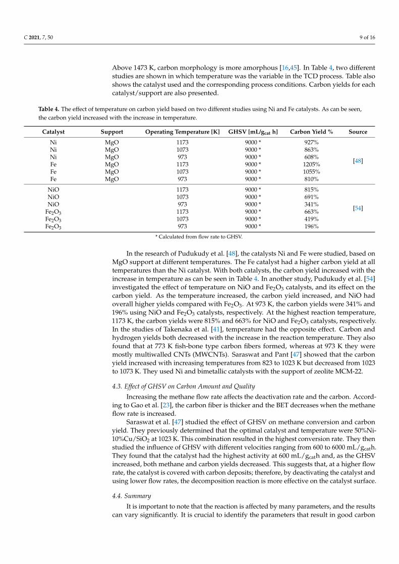
Above 1473 K, carbon morphology is more amorphous [16,45]. In Table 4, two differentstudies are shown in which temperature was the variable in the TCD process. Table alsoshows the catalyst used and the corresponding process conditions. Carbon yields for eachcatalyst/support are also presented.
Table 4. The effect of temperature on carbon yield based on two different studies using Ni and Fe catalysts. As can be seen,the carbon yield increased with the increase in temperature.
Catalyst Support Operating Temperature [K] GHSV [mL/gcat h] Carbon Yield % Source
Ni MgO 1173 9000 * 927%
[48]
Ni MgO 1073 9000 * 863%Ni MgO 973 9000 * 608%Fe MgO 1173 9000 * 1205%Fe MgO 1073 9000 * 1055%Fe MgO 973 9000 * 810%
NiO 1173 9000 * 815%
[54]
NiO 1073 9000 * 691%NiO 973 9000 * 341%
Fe2O3 1173 9000 * 663%Fe2O3 1073 9000 * 419%Fe2O3 973 9000 * 196%
* Calculated from flow rate to GHSV.
In the research of Pudukudy et al. [48], the catalysts Ni and Fe were studied, based onMgO support at different temperatures. The Fe catalyst had a higher carbon yield at alltemperatures than the Ni catalyst. With both catalysts, the carbon yield increased with theincrease in temperature as can be seen in Table 4. In another study, Pudukudy et al. [54]investigated the effect of temperature on NiO and Fe2O3 catalysts, and its effect on thecarbon yield. As the temperature increased, the carbon yield increased, and NiO hadoverall higher yields compared with Fe2O3. At 973 K, the carbon yields were 341% and196% using NiO and Fe2O3 catalysts, respectively. At the highest reaction temperature,1173 K, the carbon yields were 815% and 663% for NiO and Fe2O3 catalysts, respectively.In the studies of Takenaka et al. [41], temperature had the opposite effect. Carbon andhydrogen yields both decreased with the increase in the reaction temperature. They alsofound that at 773 K fish-bone type carbon fibers formed, whereas at 973 K they weremostly multiwalled CNTs (MWCNTs). Saraswat and Pant [47] showed that the carbonyield increased with increasing temperatures from 823 to 1023 K but decreased from 1023to 1073 K. They used Ni and bimetallic catalysts with the support of zeolite MCM-22.
4.3. Effect of GHSV on Carbon Amount and Quality
Increasing the methane flow rate affects the deactivation rate and the carbon. Accord-ing to Gao et al. [23], the carbon fiber is thicker and the BET decreases when the methaneflow rate is increased.
Saraswat et al. [47] studied the effect of GHSV on methane conversion and carbonyield. They previously determined that the optimal catalyst and temperature were 50%Ni-10%Cu/SiO2 at 1023 K. This combination resulted in the highest conversion rate. They thenstudied the influence of GHSV with different velocities ranging from 600 to 6000 mL/gcath.They found that the catalyst had the highest activity at 600 mL/gcath and, as the GHSVincreased, both methane and carbon yields decreased. This suggests that, at a higher flowrate, the catalyst is covered with carbon deposits; therefore, by deactivating the catalyst andusing lower flow rates, the decomposition reaction is more effective on the catalyst surface.
4.4. Summary
It is important to note that the reaction is affected by many parameters, and the resultscan vary significantly. It is crucial to identify the parameters that result in good carbon
C 2021, 7, 50 10 of 16
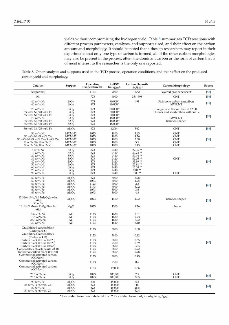
yields without compromising the hydrogen yield. Table 5 summarizes TCD reactions withdifferent process parameters, catalysts, and supports used, and their effect on the carbonamount and morphology. It should be noted that although researchers may report in theirexperiments that only one type of carbon is formed, all of the other carbon morphologiesmay also be present in the process; often, the dominant carbon or the form of carbon that isof most interest to the researcher is the only one reported.
Table 5. Other catalysts and supports used in the TCD process, operation conditions, and their effect on the producedcarbon yield and morphology.
Catalyst Support OperatingTemperature [K]
GHSV[mL/gcath]
Carbon Deposits[gC/gcat]
Carbon Morphology Source
Fe (porous) 1173 9000 6.62 Layered graphene sheets [55]
Ni 773 9000 354–398 CNT [56]
40 wt% Ni SiO2 773 90,000 * 491 Fish-bone carbon nanofibers [41]40 wt% Ni SiO2 973 90,000 * MWCNT
75 wt% Ni SiO2 823 30,000 * Longer and thicker than at 923 K
[57]35 wt% Ni/40 wt% Fe SiO2 823 30,000 * Thinner and shorter than without Fe65 wt% NI/10 wt% Fe SiO2 823 30,000 *
75 wt% Ni SiO2 923 18,000 * MWCNT35 wt% Ni/40 wt% Fe SiO2 923 18,000 * bamboo shaped65 wt% NI/10 wt% Fe SiO2 923 18,000 *
50 wt% Ni/25 wt% Fe Al2O3 973 4200 * 562 CNT [58]
50 wt% Ni MCM-22 1023 1800 3.63 CNT
[38]50 wt% Ni/5 wt% Cu MCM-22 1023 1800 4.26 CNT
50 wt% Ni/5 wt% Cu/5 wt% Zn MCM-22 1023 1800 5.68 CNT50 wt% Ni/10 wt% Cu MCM-22 1023 1800 5.5 CNT50 wt% Ni/10 wt% Zn MCM-22 1023 1800 5.45 CNT
5 wt% Ni SiO2 873 2440 27.16 **
[59]
10 wt% Ni SiO2 873 2440 39.73 **20 wt% Ni SiO2 873 2440 57.94 **30 wt% Ni SiO2 873 2440 62.05 ** CNT40 wt% Ni SiO2 873 2440 35.99 **50 wt% Ni SiO2 873 2440 23.91 **60 wt% Ni SiO2 873 2440 16.54 **70 wt% Ni SiO2 873 2440 9.01 **90 wt% Ni SiO2 873 2440 1.00 ** CNT
69 wt% Fe Al2O3 973 6000 2.28
[60]69 wt% Fe Al2O3 1073 6000 4.2569 wt% Fe Al2O3 1123 6000 2.369 wt% Fe Al2O3 1173 6000 3.0269 wt% Fe Al2O3 1073 3000 3.669 wt% Fe Al2O3 1073 8000 4.8
12.3Fe/1Mo/6.15Al2O3(molarratio) Al2O3 1023 1500 1.92 bamboo shaped [28]
50 wt%12.3Fe/1Mo/6.15MgO(molar
ratio)MgO 1023 1500 8.26 tubular
8.6 wt% Ni AC 1123 1620 7.01[61]16.6 wt% Ni AC 1123 1620 9.23
23.3 wt% Ni AC 1123 1620 7.9230 wt% Ni AC 1123 1620 6.10
Graphitized carbon black(Carbopack C) 1123 3800 0.08
[62]
Graphitized carbon black(Carbopack B) 1123 3800 0.12
Carbon black (Fluke 05120) 1123 3800 0.65Carbon black (Fluka 05120) 1123 9500 0.69Carbon black (Fluka 03866) 1123 3800 0.212
Carbon black (Black pearls 2000) 1123 3800 0.22Industrial carbon black (HS-50) 1123 3800 0.28Commercial activated carbon
(CGNorit) 1123 3800 0.45
Commercial activated carbon(CGNorit) 1123 9500 0.6
Commercial activated carbon(CGNorit) 1123 19,000 0.66
26.5 wt% Fe SiO2 1073 105,000 7.5 CNT [63]26.5 wt% Fe SiO2 1073 105,000 22.5 CNT
90 wt% Fe Al2O3 898 45,000 5.5[64]85 wt% Fe/5 wt% Co Al2O3 823 45,000 16
50 wt% Fe Al2O3 823 45,000 26.550 wt% Fe/6 wt% Co Al2O3 823 45,000 52.4
* Calculated from flow rate to GHSV. ** Calculated from molC/molNi to gC/gNi.
C 2021, 7, 50 11 of 16
5. Possible Applications for Produced Solid Carbon
Demand for carbon products is expected to grow in the future [24]. Currently, themost common production methods are plasma arc discharge, pulsed laser gasification, andcatalytic chemical vapor deposition. The first of these has a high operation temperatureof 4000–6000 K, and the latter has normal pressure and a temperature of 800–1200 K. InTCD, both products’ hydrogen and carbon may be valuable in the future; therefore, there issignificant interest in the process and applications for produced carbon. These applicationsvary depending on the type of carbon produced; for example, CNOs have been applied inlubrication oils and supercapacitors. CNTs have been used in water purification treatmentand in conductive polymers [25,65].
In this article, we introduce possible applications in which carbon materials arecurrently being used or could be used. Not all of the studies relate to carbon materialsmanufactured by TCD. Nonetheless, this process has the potential to become economicallyfeasible because, in many applications, increasing the scale of manufacturing is one ofthe biggest challenges [66]. It should be noted that, although many of these applicationshave been tested in the laboratory, they may not be ethically viable or safe for humans inpractice; a good example is water purification, because carbon nanotubes are consideredtoxic to humans [67].
5.1. Batteries
Battery manufacturers continuously attempt to improve charging rate, energy density,operating temperature, power density, safety, energy density, and sufficient electrochemicalcycling characteristics. Electrode materials play a key role in battery development. CNTshave been studied as an anode material for Li-ion batteries [68]. Traditionally, in Li-ion batteries, graphite has been used as the anode material because of its good electricconductivity. In high power applications, graphene is replaced with materials that havehigher capacity, energy, and power density. CNT morphology, high conductivity andtensile strength, and inertness to chemical degradation can improve battery capacity anddecrease the risk of pulverization as an anode material, and can therefore be consideredas a replacement material for graphene. If CNTs are used in batteries, they should be freefrom contaminants, such as metal catalysts, amorphous carbon, fullerenes, and nanotubeswith divergent morphology. Large-scale production is still under development and theprices remain relatively high.
5.2. Supercapacitors
TCD-produced carbon provides a less-expensive, environmentally friendly choicefor supercapacitor materials, without compromising the material properties required [68].Porous carbon materials are attractive materials for the production of electrodes due totheir high thermal and chemical stability, good electrical conductivity, and porous structure.Optimal supercapacitor materials should have an accessible and high specific surface areain the microporous region. A certain balance should be obtained between the energystorage-related pores and interconnecting pores to achieve the best properties; therefore,the ability to control the porosity of the carbon by production parameters is crucial [31].
5.3. Water Treatment Application
Because CNTs have a relatively large specific surface area and a porous structure, theymay be used as an absorbent of organic pollutants from wastewater [69,70]. AlthoughCNTs show promise in this regard, a number critical obstacles must first be overcome. Firstis the poor separability of the carbon and pollutant. Second is that studies have shown thatCNTs’ only have the ability to absorb a single organic pollutant, whereas wastewater canhave several pollutants, such as metal ions, anions, humic acid, and organic solvents. Thirdis the economic issue. Thus, in the more practical applications of CNTs, more attentionshould paid to finding means to make the operation more feasible for water treatment [71].
C 2021, 7, 50 12 of 16
CNTs can also be toxic to the human body [72,73], and therefore, it should be carefullyconsidered whether they should be applied to wastewater treatment.
5.4. Composite Materials
MWCNTs may be used as a composite material. Combined with polymers, severalapplications are possible [74]. This composite material may be used, for example, inwearable electronics in textile sectors [75], antennas [76], sensors [77], solar cells [78,79],and EMI shielding [80–83]. The use of these materials can also overcome existing challengesand allow industrialization of new applications, such as healthcare devices, packaging, andshield protection for humans. Previous studies have also noted that this type of compositematerial may replace steel in various appliances due to its superior electric conductivity.
5.5. Cosmetics and Medical Applications
Carbon-based nanoparticles are being used in cosmetics and medical applications.For example, fullerenes have potential in biomedicine because of their antioxidant activity.They show promise in dermatological and skin care products, such as sunscreen, skinwhitening, and antiaging products [83]. Fullerenes can act as a vehicle to improve drugdelivery and hair growth. Carbon black can be used as a colorant in cosmetic products, andactivated carbon is used in toothpastes [80,81]. Charcoal has been used in medicine datingback to ancient Egyptian civilizations. Currently, charcoal is used for teeth whitening,smoothing the skin, facial cleansing, pore striping, facial masks, and soaps. It has beennoted that it can treat acne, bites or cuts, minor infections, itchy scalp, and seborrheicdermatitis. Activated charcoal removes dirt, oil, and impurities, absorbs toxins, has anti-bacterial properties, tightens pores, smooths skin, reduces inflammation, and decongestsand brightens the skin [82].
6. Conclusions
CO2-free hydrogen production is a key area in the effort to achieve the EU’s ambitiousenvironmental and carbon neutrality goals. TCD, which is a CO2-free process, may be usedin the future to produce both hydrogen and solid carbon. In this article, we focused on theproduction of solid carbon, including its properties, the effect of the TCD process on itsquality, and its possible applications. Carbon produced using TCD could have a significanteffect on the hydrogen economy and increase the value added by the process. Comparedto other methane-based hydrogen production processes, this carbon is bound in a solidform and can be used in carbon capture with zero CO2 emissions.
Carbon can take several forms, such as graphene, diamond, fullerenes, and nanotubes.These different morphologies can have various properties and applications. Therefore,understanding the manufacturing process and parameter effects is crucial to obtain thequality that is desired for the application. In the TCD catalyst, the promoter, temperature,and methane gas flow can influence the carbon type and quality.
Because carbon materials are currently widely used or studied for various applications,carbon manufactured by TCD could provide the impetus for its use in several applicationareas, such as batteries, supercapacitors, and composite material. This would increase theirpotential uses, and make them more economically friendly and feasible. However, in someapplications, such as water purification, CNT toxicity to humans remains an issue thatmust be considered.
Author Contributions: Conceptualization, U.L., H.R., E.V. and L.Y.-V.; Writing—original draftpreparation, E.V.; Writing—review and editing, U.L, H.R., E.V. and L.Y.-V.; visualization, U.L., H.R.;supervision, U.L.; funding acquisition, E.V., U.L. and H.R. All authors have read and agreed to thepublished version of the manuscript.
Funding: This research was funded by the Fortum and Neste Foundation, grant number 20200148.
Institutional Review Board Statement: Not applicable.
C 2021, 7, 50 13 of 16
Informed Consent Statement: Not applicable.
Conflicts of Interest: The authors declare no conflict of interest in regard to this work.
References1. European Comission. A Hydrogen Strategy for a Climate-Neutral Europe; European Commission: Brussels, Belgium, 2020.2. Yang, L.; Liu, F.; He, J. Natural Sand as a Non-Conventional Catalyst for Hydrogen Production by Methane Thermo-Catalytic
Decomposition. Int. J. Hydrogen Energy 2019, 44, 11625–11633. [CrossRef]3. Gamal, A.; Eid, K.; El-Naas, M.H.; Kumar, D.; Kumar, A. Catalytic Methane Decomposition to Carbon Nanostructures and
Cox-Free Hydrogen: A Mini-Review. Nanomaterials 2021, 11, 1226. [CrossRef] [PubMed]4. Chen, L.; Qi, Z.; Zhang, S.; Su, J.; Somorjai, G.A. Catalytic Hydrogen Production from Methane: A Review on Recent Progress
and Prospect. Catalysts 2020, 10, 858. [CrossRef]5. Abbas, H.F.; Wan Daud, W.M.A. Hydrogen Production by Methane Decomposition: A Review. Int. J. Hydrogen Energy 2010, 35,
1160–1190. [CrossRef]6. Abdullah, B.; Abd Ghani, N.A.; Vo, D.V.N. Recent Advances in Dry Reforming of Methane over Ni-Based Catalysts. J. Clean. Prod.
2017, 162, 170–185. [CrossRef]7. Soltani, R.; Rosen, M.A.; Dincer, I. Assessment of CO2 Capture Options from Various Points in Steam Methane Reforming for
Hydrogen Production. Int. J. Hydrogen Energy 2014, 39, 20266–20275. [CrossRef]8. Usman, M.; Wan Daud, W.M.A.; Abbas, H.F. Dry Reforming of Methane: Influence of Process Parameters—A Review. Renew.
Sustain. Energy Rev. 2015, 45, 710–744. [CrossRef]9. Levalley, T.L.; Richard, A.R.; Fan, M. The Progress in Water Gas Shift and Steam Reforming Hydrogen Production Technologies—A
Review. Int. J. Hydrogen Energy 2014, 39, 16983–17000. [CrossRef]10. Kumar, S.; Kumar, S.; Prajapati, J.K. Hydrogen Production by Partial Oxidation of Methane: Modeling and Simulation. Int. J.
Hydrogen Energy 2009, 34, 6655–6668. [CrossRef]11. De, C.; Roseno, K.T.; Schmal, M.; Brackmann, R.; Alves, R.M.B.; Giudici, R. Partial Oxidation of Methane on Neodymium and
Lanthanium Chromate Based Perovskites for Hydrogen Production. Int. J. Hydrogen Energy 2019, 44, 8166–8177. [CrossRef]12. Larimi, A.S.; Alavi, S.M. Ceria-Zirconia Supported Ni Catalysts for Partial Oxidation of Methane to Synthesis Gas. Fuel 2012, 102,
366–371. [CrossRef]13. Ruckenstein, E.; Hu, Y.H. Methane Partial Oxidation over NiO/MgO Solid Solution Catalysts. Appl. Catal. A Gen. 1999, 183,
85–92. [CrossRef]14. Ibrahim, A.A.; Al-Fatesh, A.S.; Khan, W.U.; Soliman, M.A.; Al Otaibi, R.L.; Fakeeha, A.H. Thermo-Catalytic Methane Decomposi-
tion: A Review of State of the Art of Catalysts. J. Chem. Soc. Pakistan 2015, 37, 1269–1297.15. Ashik, U.P.M.; Wan Daud, W.M.A.; Abbas, H.F. Production of Greenhouse Gas Free Hydrogen by Thermocatalytic Decomposition
of Methane—A Review. Renew. Sustain. Energy Rev. 2015, 44, 221–256. [CrossRef]16. Keipi, T.; Tolvanen, K.E.S.; Tolvanen, H.; Konttinen, J. Thermo-Catalytic Decomposition of Methane: The Effect of Reaction
Parameters on Process Design and the Utilization Possibilities of the Produced Carbon. Energy Convers. Manag. 2016, 126, 923–934.[CrossRef]
17. Pudukudy, M.; Yaakob, Z.; Akmal, Z.S. Direct Decomposition of Methane over SBA-15 Supported Ni, Co and Fe Based BimetallicCatalysts. Appl. Surf. Sci. 2015, 330, 418–430. [CrossRef]
18. Liang, W.; Yan, H.; Chen, C.; Lin, D.; Tan, K.; Feng, X.; Liu, Y.; Chen, X.; Yang, C.; Shan, H. Revealing the Effect of Nickel ParticleSize on Carbon Formation Type in the Methane Decomposition Reaction. Catalysts 2020, 10, 890. [CrossRef]
19. Zhou, L.; Enakonda, L.R.; Harb, M.; Saih, Y.; Aguilar-Tapia, A.; Ould-Chikh, S.; Hazemann, J.-l.; Li, J.; Wei, N.; Gary, D.; et al. FeCatalysts for Methane Decomposition to Produce Hydrogen and Carbon Nano Materials. Appl. Catal. B Environ. 2017, 208, 44–59.[CrossRef]
20. Callister, W.D. Materials Science and Engineering: An Introduction, 7th ed.; John Wiley & Sons: New York, NY, USA, 2007.21. Noked, M.; Soffer, A.; Arubach, D. The Electrochemistry of Activated Carbonaceous Materials: Past, Present, and Future. J. Solid
State Electrochem. 2011, 15, 1563–1578. [CrossRef]22. Qian, J.X.; Chen, T.W.; Enakonda, L.R.; Liu, D.B.; Basset, J.M.; Zhou, L. Methane Decomposition to Pure Hydrogen and Carbon
Nano Materials: State-of-the-Art and Future Perspectives. Int. J. Hydrogen Energy 2020, 45, 15721–15743. [CrossRef]23. Gao, L.Z.; Kiwi-Minsker, L.; Renken, A. Growth of Carbon Nanotubes and Microfibers over Stainless Steel Mesh by Cracking of
Methane. Surf. Coatings Technol. 2008, 202, 3029–3042. [CrossRef]24. Torres, D.; Pinilla, J.L.; Suelves, I. Cobalt Doping of α-Fe/Al2O3 Catalysts for the Production of Hydrogen and High-Quality
Carbon Nanotubes by Thermal Decomposition of Methane. Int. J. Hydrogen Energy 2020, 45, 19313–19323. [CrossRef]25. Liu, Q.; Wu, P.; He, J.; Liu, C.; Jiang, W. Catalytic Decomposition of Methane by Two-Step Cascade Catalytic Process: Simultaneous
Production of Hydrogen and Carbon Nanotubes. Chem. Eng. Res. Des. 2020, 163, 96–106. [CrossRef]26. Soni, S.K.; Thomas, B.; Kar, V.R. A Comprehensive Review on CNTs and CNT-Reinforced Composites: Syntheses, Characteristics
and Applications. Mater. Today Commun. 2020, 25, 101546. [CrossRef]27. Awadallah, A.E.; El-Desouki, D.S.; Aboul-Gheit, N.A.K.; Ibrahim, A.H.; Aboul-Gheit, A.K. Effect of Crystalline Structure and
Pore Geometry of Silica Based Supported Materials on the Catalytic Behavior of Metallic Nickel Particles during MethaneDecomposition to COx-Free Hydrogen and Carbon Nanomaterials. Int. J. Hydrogen Energy 2016, 41, 16890–16902. [CrossRef]
C 2021, 7, 50 14 of 16
28. Torres, D.; Pinilla, J.L.; Lázaro, M.J.; Moliner, R.; Suelves, I. Hydrogen and Multiwall Carbon Nanotubes Production by CatalyticDecomposition of Methane: Thermogravimetric Analysis and Scaling-up of Fe-Mo Catalysts. Int. J. Hydrogen Energy 2014, 39,3698–3709. [CrossRef]
29. Williams, P.T. Hydrogen and Carbon Nanotubes from Pyrolysis-Catalysis of Waste Plastics: A Review. Waste Biomass Valorization2020, 12, 1–28. [CrossRef]
30. Dagle, R.; Dagle, V.; Bearden, M.; Holladay, J.; Krause, T.; Ahmed, S. R & D Opportunities for Development of Natural Gas ConversionTechnologies for Co-Production of Hydrogen and Value-Added Solid Carbon Products; U.S. Department of Energy Fuel Cell TechnologiesOffice: Chicago, IL, USA, 2017.
31. Gu, W.; Yushin, G. Review of Nanostructured Carbon Materials for Electrochemical Capacitor Applications: Advantages andLimitations of Activated Carbon, Carbide-Derived Carbon, Zeolite-Templated Carbon, Carbon Aerogels, Carbon Nanotubes,Onion-like Carbon, and Graphene. Wiley Interdiscip. Rev. Energy Environ. 2014, 3, 424–473. [CrossRef]
32. Han, F.D.; Yao, B.; Bai, Y.J. Preparation of Carbon Nano-Onions and Their Application as Anode Materials for RechargeableLithium-Ion Batteries. J. Phys. Chem. C 2011, 115, 8923–8927. [CrossRef]
33. Bai, Z.; Chen, H.; Li, B.; Li, W. Methane Decomposition over Ni Loaded Activated Carbon for Hydrogen Production and theFormation of Filamentous Carbon. Int. J. Hydrogen Energy 2007, 32, 32–37. [CrossRef]
34. Lobo, L.S.; Carabineiro, S.A.C. Carbon Formation at High Temperatures. Catalysts 2020, 10, 465. [CrossRef]35. Guizani, C.; Escudero Sanz, F.J.; Salvador, S. The Nature of the Deposited Carbon at Methane Cracking over a Nickel Loaded
Wood-Char. Comptes Rendus Chim. 2016, 19, 423–432. [CrossRef]36. Torres, D.; Pinilla, J.L.; Suelves, I. Co-, Cu-and Fe-Doped Ni/Al2o3 Catalysts for the Catalytic Decomposition of Methane into
Hydrogen and Carbon Nanofibers. Catalysts 2018, 8, 300. [CrossRef]37. Upham, D.C.; Agarwal, V.; Khechfe, A.; Snodgrass, Z.R.; Gordon, M.J.; Metiu, H.; McFarland, E.W. Catalytic Molten Metals for
the Direct Conversion of Methane to Hydrogen and Separable Carbon. Science 2017, 358, 917–921. [CrossRef]38. Saraswat, S.K.; Pant, K.K. Ni-Cu-Zn/MCM-22 Catalysts for Simultaneous Production of Hydrogen and Multiwall Carbon
Nanotubes via Thermo-Catalytic Decomposition of Methane. Int. J. Hydrogen Energy 2011, 36, 13352–13360. [CrossRef]39. Christensen, K.O.; Chen, D.; Lødeng, R.; Holmen, A. Effect of Supports and Ni Crystal Size on Carbon Formation and Sintering
during Steam Methane Reforming. Appl. Catal. A Gen. 2006, 314, 9–22. [CrossRef]40. Hasnan, N.S.N.; Timmiati, S.N.; Lim, K.L.; Yaakob, Z.; Kamaruddin, N.H.N.; Teh, L.P. Recent Developments in Methane
Decomposition over Heterogeneous Catalysts: An Overview. Mater. Renew. Sustain. Energy 2020, 9, 3. [CrossRef]41. Takenaka, S.; Kobayashi, S.; Ogihara, H.; Otsuka, K. Ni/SiO2 Catalyst Effective for Methane Decomposition into Hydrogen and
Carbon Nanofiber. J. Catal. 2003, 217, 79–87. [CrossRef]42. Marquardt, T.; Bode, A.; Kabelac, S. Hydrogen Production by Methane Decomposition: Analysis of Thermodynamic Carbon
Properties and Process Evaluation. Energy Convers. Manag. 2020, 221. [CrossRef]43. Guil-Lopez, R.; Botas, J.A.; Fierro, J.L.G.; Serrano, D.P. Comparison of Metal and Carbon Catalysts for Hydrogen Production by
Methane Decomposition. Appl. Catal. A Gen. 2011, 396, 40–51. [CrossRef]44. Muradov, N.; Smith, F.; T-Raissi, A. Catalytic Activity of Carbons for Methane Decomposition Reaction. Catal. Today 2005, 102–103,
225–233. [CrossRef]45. Ahmed, S.; Aitani, A.; Rahman, F.; Al-Dawood, A.; Al-Muhaish, F. Decomposition of Hydrocarbons to Hydrogen and Carbon.
Appl. Catal. A Gen. 2009, 359, 1–24. [CrossRef]46. Qian, J.X.; Chen, T.W.; Enakonda, L.R.; Liu, D.B.; Mignani, G.; Basset, J.M.; Zhou, L. Methane Decomposition to Produce COx-Free
Hydrogen and Nano-Carbon over Metal Catalysts: A Review. Int. J. Hydrogen Energy 2020, 45, 7981–8001. [CrossRef]47. Saraswat, S.K.; Pant, K.K. Synthesis of Hydrogen and Carbon Nanotubes over Copper Promoted Ni/SiO2 Catalyst by Thermocat-
alytic Decomposition of Methane. J. Nat. Gas Sci. Eng. 2013, 13, 52–59. [CrossRef]48. Pudukudy, M.; Yaakob, Z.; Mazuki, M.Z.; Takriff, M.S.; Jahaya, S.S. One-Pot Sol-Gel Synthesis of MgO Nanoparticles Supported
Nickel and Iron Catalysts for Undiluted Methane Decomposition into COx Free Hydrogen and Nanocarbon. Appl. Catal. BEnviron. 2017, 218, 298–316. [CrossRef]
49. Takenaka, S.; Shigeta, Y.; Tanabe, E.; Otsuka, K. Methane Decomposition into Hydrogen and Carbon Nanofibers over SupportedPd-Ni Catalysts. J. Catal. 2003, 220, 468–477. [CrossRef]
50. Munera Parra, A.A.; Agar, D.W. Molten Metal Capillary Reactor for the High-Temperature Pyrolysis of Methane. Int. J. HydrogenEnergy 2017, 42, 13641–13648. [CrossRef]
51. Guo, Z.; Zheng, J.E.; Liu, Y.; Chu, W. Insight into the Role of Metal/Oxide Interaction and Ni Availabilities on NiAl Mixed MetalOxide Catalysts for Methane Decomposition. Appl. Catal. A Gen. 2018, 555, 1–11. [CrossRef]
52. Ermakova, M.A.; Ermakov, D.Y. Ni/SiO2 and Fe/SiO2 Catalysts for Production of Hydrogen and Filamentous Carbon viaMethane Decomposition. Catal. Today 2002, 77, 225–235. [CrossRef]
53. Inaba, M.; Zhang, Z.; Matsuoka, K.; Soneda, Y. Optimization of the Reaction Conditions for Fe-Catalyzed Decomposition ofMethane and Characterization of the Produced Nanocarbon Fibers. Catal. Today 2019, 332, 11–19. [CrossRef]
54. Pudukudy, M.; Yaakob, Z.; Dahani, N.; Takriff, M.S.; Hassan, N.S.M. Production of COx Free Hydrogen and Nanocarbon viaMethane Decomposition Over Unsupported Porous Nickel and Iron Catalysts. J. Clust. Sci. 2017, 28, 1579–1594. [CrossRef]

C 2021, 7, 50 15 of 16
55. Pudukudy, M.; Yaakob, Z.; Kadier, A.; Takriff, M.S.; Hassan, N.S.M. One-Pot Sol–Gel Synthesis of Ni/TiO2 Catalysts for MethaneDecomposition into COx Free Hydrogen and Multiwalled Carbon Nanotubes. Int. J. Hydrogen Energy 2017, 42, 16495–16513.[CrossRef]
56. Li, Y.; Zhang, B.; Xie, X.; Liu, J.; Xu, Y.; Shen, W. Novel Ni Catalysts for Methane Decomposition to Hydrogen and CarbonNanofibers. J. Catal. 2006, 238, 412–424. [CrossRef]
57. Wang, W.; Wang, H.; Yang, Y.; Jiang, S. Ni-SiO2 and Ni-Fe-SiO2 Catalysts for Methane Decomposition to Prepare Hydrogen andCarbon Filaments. Int. J. Hydrogen Energy 2012, 37, 9058–9066. [CrossRef]
58. Wang, G.; Jin, Y.; Liu, G.; Li, Y. Production of Hydrogen and Nanocarbon from Catalytic Decomposition of Methane over aNi-Fe/Al2O3 Catalyst. Energy Fuels 2013, 27, 4448–4456. [CrossRef]
59. Venugopal, A.; Naveen Kumar, S.; Ashok, J.; Hari Prasad, D.; Durga Kumari, V.; Prasad, K.B.S.; Subrahmanyam, M. HydrogenProduction by Catalytic Decomposition of Methane over Ni/SiO2. Int. J. Hydrogen Energy 2007, 32, 1782–1788. [CrossRef]
60. Torres, D.; De Llobet, S.; Pinilla, J.L.; Lázaro, M.J.; Suelves, I.; Moliner, R. Hydrogen Production by Catalytic Decomposition ofMethane Using a Fe-Based Catalyst in a Fluidized Bed Reactor. J. Nat. Gas Chem. 2012, 21, 367–373. [CrossRef]
61. Sarada Prasad, J.; Dhand, V.; Himabindu, V.; Anjaneyulu, Y. Production of Hydrogen and Carbon Nanofibers through theDecomposition of Methane over Activated Carbon Supported Ni Catalysts. Int. J. Hydrogen Energy 2011, 36, 11702–11711.[CrossRef]
62. Suelves, I.; Lázaro, M.J.; Moliner, R.; Pinilla, J.L.; Cubero, H. Hydrogen Production by Methane Decarbonization: CarbonaceousCatalysts. Int. J. Hydrogen Energy 2007, 32, 3320–3326. [CrossRef]
63. Takenaka, S.; Serizawa, M.; Otsuka, K. Formation of Filamentous Carbons over Supported Fe Catalysts through MethaneDecomposition. J. Catal. 2004, 222, 520–531. [CrossRef]
64. Avdeeva, L.B.; Reshetenko, T.V.; Ismagilov, Z.R.; Likholobov, V.A. Iron-Containing Catalysts of Methane Decomposition:Accumulation of Filamentous Carbon. Appl. Catal. A Gen. 2002, 228, 53–63. [CrossRef]
65. Fau, G.; Gascoin, N.; Gillard, P.; Steelant, J. Methane Pyrolysis: Literature Survey and Comparisons of Available Data for Use inNumerical Simulations. J. Anal. Appl. Pyrolysis 2013, 104, 1–9. [CrossRef]
66. Rashed, A.O.; Merenda, A.; Kondo, T.; Lima, M.; Razal, J.; Kong, L.; Huynh, C.; Dumée, L.F. Carbon Nanotube Membranes—Strategies and Challenges towards Scalable Manufacturing and Practical Separation Applications. Sep. Purif. Technol. 2021, 257,117929. [CrossRef]
67. Ahmad, J.; Naeem, S.; Ahmad, M.; Usman, A.R.A.; Al-Wabel, M.I. A Critical Review on Organic Micropollutants Contaminationin Wastewater and Removal through Carbon Nanotubes. J. Environ. Manag. 2019, 246, 214–228. [CrossRef] [PubMed]
68. Maziarka, P.; Sommersacher, P.; Wang, X.; Kienzl, N.; Retschitzegger, S.; Prins, W.; Hedin, N.; Ronsse, F. Tailoring of the PoreStructures of Wood Pyrolysis Chars for Potential Use in Energy Storage Applications. Appl. Energy 2021, 286, 116431. [CrossRef]
69. Peng, X.; Li, Y.; Luan, Z.; Di, Z.; Wang, H.; Tian, B.; Jia, Z. Adsorption of 1,2-Dichlorobenzene from Water to Carbon Nanotubes.Chem. Phys. Lett. 2003, 376, 154–158. [CrossRef]
70. Avcı, A.; Inci, I.; Baylan, N. Adsorption of Ciprofloxacin Hydrochloride on Multiwall Carbon Nanotube. J. Mol. Struct. 2020, 1206,127711. [CrossRef]
71. Peng, J.; He, Y.; Zhou, C.; Su, S.; Lai, B. The Carbon Nanotubes-Based Materials and Their Applications for Organic PollutantRemoval: A Critical Review. Chin. Chem. Lett. 2021. [CrossRef]
72. Mohanta, D.; Patnaik, S.; Sood, S.; Das, N. Carbon Nanotubes: Evaluation of Toxicity at Biointerfaces. J. Pharm. Anal. 2019, 9,293–300. [CrossRef]
73. Keipi, T.; Hankalin, V.; Nummelin, J.; Raiko, R. Techno-Economic Analysis of Four Concepts for Thermal Decomposition ofMethane: Reduction of CO2 Emissions in Natural Gas Combustion. Energy Convers. Manag. 2016, 110, 1–12. [CrossRef]
74. Dhineshbabu, N.R.; Mahadevi, N.; Assein, D. Electronic Applications of Multi-Walled Carbon Nanotubes in Polymers: A ShortReview. Mater. Today Proc. 2020. [CrossRef]
75. Wang, X.; Yang, B.; Liu, J.; Zhu, Y.; Yang, C.; He, Q. A Flexible Triboelectric-Piezoelectric Hybrid Nanogenerator Based onP(VDF-TrFE) Nanofibers and PDMS/MWCNT for Wearable Devices. Sci. Rep. 2016, 6. [CrossRef]
76. Zahir, H.; Wojkiewicz, J.; Alexander, P.; Kone, L.; Belkacem, B.; Bergheul, S.; Lasri, T. Design Fabrication and Characterisation ofPolyaniline and Multiwall Carbon Nanotubes Composites-based Patch Antenna. IET Microw. Antennas Propag. 2016, 10, 88–93.[CrossRef]
77. Turkani, V.S.; Maddipatla, D.; Narakathu, B.B.; Saeed, T.S.; Obare, S.O.; Bazuin, B.J.; Atashbar, M.Z. A Highly Sensitive PrintedHumidity Sensor Based on a Functionalized MWCNT/HEC Composite for Flexible Electronics Application. Nanoscale Adv. 2019,1, 2311–2322. [CrossRef]
78. Kim, D.H.; Dudem, B.; Yu, J.S. High-Performance Flexible Piezoelectric-Assisted Triboelectric Hybrid Nanogenerator viaPolydimethylsiloxane-Encapsulated Nanoflower-like ZnO Composite Films for Scavenging Energy from Daily Human Activities.ACS Sustain. Chem. Eng. 2018, 6, 8525–8535. [CrossRef]
79. Kar, E.; Bose, N.; Dutta, B.; Mukherjee, N.; Mukherjee, S. MWCNT@SiO2 Heterogeneous Nanofiller-Based Polymer Composites:A Single Key to the High-Performance Piezoelectric Nanogenerator and X-Band Microwave Shield. ACS Appl. Nano Mater. 2018,1, 4005–4018. [CrossRef]
80. Rincon, A.M. Chapter 6—Presence of nanomaterials on consumer products: Food, cosmetics, and drugs. In Exposure to EngineeredNanomaterials in the Environment; Elsevier: Amsterdam, The Netherlands, 2019; pp. 165–181, ISBN 9780128148365.

C 2021, 7, 50 16 of 16
81. Viana, Í.E.L.; Weiss, G.S.; Sakae, L.O.; Niemeyer, S.H.; Borges, A.B.; Scaramucci, T. Activated Charcoal Toothpastes Do NotIncrease Erosive Tooth Wear. J. Dent. 2021, 109, 103677. [CrossRef]
82. Sanchez, N.; Fayne, R.; Burroway, B. Charcoal: An Ancient Material with a New Face. Clin. Dermatol. 2020, 38, 262–264. [CrossRef][PubMed]
83. Nafisi, S.; Maibach, H.I. Nanotechnology in cosmetics. In Cosmetic Science and Technology: Theoretical Principles and Applications;Elsevier: Amsterdam, The Netherlands, 2017; pp. 337–361, ISBN 9780128020548.