Embed Size (px)
Citation preview
Care and Maintenanceequipment standards – equipment wear and failure – routine checks and care
239B BMC C&M Cover Collect 1/11/07 4:17 PM Page 1
59
2. Useful books and publications
There are many textbooks available covering in-depth the techniques required to make safe useof climbing and mountaineering equipment.Much of what they say is relevant to care andmaintenance of your equipment, mainly underthe ‘how to prevent failure during use’ banner.Some of the better sources are:
The Handbook of Climbing (Fyffe & Peter)
Climbing Anchors: How to rock climb (Long)
Complete guide to rope techniques (Shepherd)
How to rock climb (Long)
Ice world (Lowe)
Mountaincraft & Leadership (Langmuir)
Extreme Alpinism (Twight)
Ice tools & techniques (Climbing magazine)
3. Other resources
BMC website – www.thebmc.co.ukA full list of the reports held at the BMC oninvestigations into equipment failures can beobtained from the technical section of the website,or from the BMC office.You will also find regularupdates on current research and importantinvestigations here.
UIAA journal – available from www.uiaa.chor +41 31.370.18.28Regular technical articles are run in the journal ofthe world body for mountaineering. Copies aremailed direct to affiliated federations, and thesearticles will be reproduced in Summit magazine ifrelevant.
Manufacturers’ Catalogues and WebsitesThese often go into a good amount of detailregarding the construction and testing ofequipment. Particularly useful are catalogues fromBeal, Petzl and DMM. Black Diamond occasionallyproduce information leaflets about new productsand their own testing programmes.
Cave Rock, Lake Tahoe Photo: Alex Messenger
239B BMC C&M Cover Collect 1/11/07 4:17 PM Page 2

iii
Introduction . . . . . . . . . . . . . . . . . . . . . . . . . . . . . . . . . . . . . . . . . . . . . . . . . . . . . . . . . . . . . . . . . . . . . . . . . . . . . . . . . . . . . . . . . . . . . . . . . . . . . . . . . . . . . . . . . . . . . . . . . . . . . . . . . . . . . . . . . . v
METALLIC EQUIPMENT
Karabiners . . . . . . . . . . . . . . . . . . . . . . . . . . . . . . . . . . . . . . . . . . . . . . . . . . . . . . . . . . . . . . . . . . . . . . . . . . . . . . . . . . . . . . . . . . . . . . . . . . . . . . . . . . . . . . . . . . . . . . . . . . . . . . . . . . . . . . . . . . . . . 1by Neville McMillan
Crampons . . . . . . . . . . . . . . . . . . . . . . . . . . . . . . . . . . . . . . . . . . . . . . . . . . . . . . . . . . . . . . . . . . . . . . . . . . . . . . . . . . . . . . . . . . . . . . . . . . . . . . . . . . . . . . . . . . . . . . . . . . . . . . . . . . . . . . . . . . . . . . . 7by Alan Huyton
Ice Tools . . . . . . . . . . . . . . . . . . . . . . . . . . . . . . . . . . . . . . . . . . . . . . . . . . . . . . . . . . . . . . . . . . . . . . . . . . . . . . . . . . . . . . . . . . . . . . . . . . . . . . . . . . . . . . . . . . . . . . . . . . . . . . . . . . . . . . . . . . . . . . . 11by Trevor Hellen
Chocks . . . . . . . . . . . . . . . . . . . . . . . . . . . . . . . . . . . . . . . . . . . . . . . . . . . . . . . . . . . . . . . . . . . . . . . . . . . . . . . . . . . . . . . . . . . . . . . . . . . . . . . . . . . . . . . . . . . . . . . . . . . . . . . . . . . . . . . . . . . . . . . . . . 15by Dick Peart
Camming Devices . . . . . . . . . . . . . . . . . . . . . . . . . . . . . . . . . . . . . . . . . . . . . . . . . . . . . . . . . . . . . . . . . . . . . . . . . . . . . . . . . . . . . . . . . . . . . . . . . . . . . . . . . . . . . . . . . . . . . . . . . . . . . . . . 19by Alan Huyton
Ascenders . . . . . . . . . . . . . . . . . . . . . . . . . . . . . . . . . . . . . . . . . . . . . . . . . . . . . . . . . . . . . . . . . . . . . . . . . . . . . . . . . . . . . . . . . . . . . . . . . . . . . . . . . . . . . . . . . . . . . . . . . . . . . . . . . . . . . . . . . . . . . 23by Ben Lyon
Belaying & Abseiling devices . . . . . . . . . . . . . . . . . . . . . . . . . . . . . . . . . . . . . . . . . . . . . . . . . . . . . . . . . . . . . . . . . . . . . . . . . . . . . . . . . . . . . . . . . . . . . . . . . . . . . . . . . . . . . 29by Ben Lyon
Appendix – Principal degradation mechanisms . . . . . . . . . . . . . . . . . . . . . . . . . . . . . . . . . . . . . . . . . . . . . . . . . . . . . . . . . . . . . . . . . . . . . . . . . . . . . 33by Neville McMillan, Rob Allen & Trevor Hellen
NON-METALLIC EQUIPMENT
Helmets . . . . . . . . . . . . . . . . . . . . . . . . . . . . . . . . . . . . . . . . . . . . . . . . . . . . . . . . . . . . . . . . . . . . . . . . . . . . . . . . . . . . . . . . . . . . . . . . . . . . . . . . . . . . . . . . . . . . . . . . . . . . . . . . . . . . . . . . . . . . . . . . 39by Dave Brook
TEXTILE EQUIPMENT
Ropes . . . . . . . . . . . . . . . . . . . . . . . . . . . . . . . . . . . . . . . . . . . . . . . . . . . . . . . . . . . . . . . . . . . . . . . . . . . . . . . . . . . . . . . . . . . . . . . . . . . . . . . . . . . . . . . . . . . . . . . . . . . . . . . . . . . . . . . . . . . . . . . . . . . . 43by Dave Brook
Harnesses . . . . . . . . . . . . . . . . . . . . . . . . . . . . . . . . . . . . . . . . . . . . . . . . . . . . . . . . . . . . . . . . . . . . . . . . . . . . . . . . . . . . . . . . . . . . . . . . . . . . . . . . . . . . . . . . . . . . . . . . . . . . . . . . . . . . . . . . . . . . . 47by George Steele
Slings . . . . . . . . . . . . . . . . . . . . . . . . . . . . . . . . . . . . . . . . . . . . . . . . . . . . . . . . . . . . . . . . . . . . . . . . . . . . . . . . . . . . . . . . . . . . . . . . . . . . . . . . . . . . . . . . . . . . . . . . . . . . . . . . . . . . . . . . . . . . . . . . . . . . 51by Dave Brook
Appendix – Principal degradation mechanisms . . . . . . . . . . . . . . . . . . . . . . . . . . . . . . . . . . . . . . . . . . . . . . . . . . . . . . . . . . . . . . . . . . . . . . . . . . . . . 54by Stuart Ingram
Appendix – Forces, kN & dynamic loads . . . . . . . . . . . . . . . . . . . . . . . . . . . . . . . . . . . . . . . . . . . . . . . . . . . . . . . . . . . . . . . . . . . . . . . . . . . . . . . . . . . . . . . . . 56by Neville McMillan
Further Reading and References . . . . . . . . . . . . . . . . . . . . . . . . . . . . . . . . . . . . . . . . . . . . . . . . . . . . . . . . . . . . . . . . . . . . . . . . . . . . . . . . . . . . . . . . . . . . . . . . . . . . . . 58
Care & Maintenanceequipment standards – equipment wear and failure – routine checks and care
BMC Care & Maint Inside 4 1/11/07 4:01 PM Page iii
iv
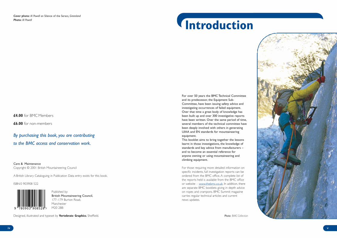
For over 50 years the BMC Technical Committeeand its predecessor, the Equipment Sub-Committee, have been issuing safety advice andinvestigating occurrences of failed equipment.Over that time a great body of knowledge hasbeen built up and over 300 investigative reportshave been written. Over the same period of time,several members of the technical committee havebeen deeply involved with others in generatingUIAA and EN standards for mountaineeringequipment.This booklet aims to bring together the lessonslearnt in those investigations, the knowledge ofstandards and key advice from manufacturers –and to become an essential reference foranyone owning or using mountaineering andclimbing equipment.
For those requiring more detailed information onspecific incidents, full investigation reports can beordered from the BMC office. A complete list ofthe reports held is available from the BMC officeor website – www.thebmc.co.uk. In addition, thereare separate BMC booklets giving in depth adviceon ropes and crampons. BMC Summit magazinecarries regular technical articles and currentnews updates.
Photo: BMC Collection
v
Introduction
£4.00 for BMC Members
£6.00 for non-members
By purchasing this book, you are contributing
to the BMC access and conservation work.
Care & MaintenanceCopyright © 2001 British Mountaineering Council
A British Library Cataloguing in Publication Data entry exists for this book.
ISBN 0 903908 522
Published by:British Mountaineering Council,177–179 Burton Road,ManchesterM20 2BB
Designed, illustrated and typeset by Vertebrate Graphics, Sheffield.
Cover photo: Al Powell on Silence of the Seracs, GreenlandPhoto: Al Powell
9 780903 908528 >
BMC Care & Maint Inside 4 1/11/07 4:01 PM Page iv
IntroductionDefines the equipment covered, and may includea brief history of its development if appropriate.
Relevant European StandardsDetails the UIAA and EN standards that theequipment must meet. It should be rememberedthat these standards are specified for normal andreasonable use, and that any item of equipmentmeeting that standard may fail if subjected tohigh or abnormal loads. It is a mistake to assumethat equipment made to these standardswill never break.
Observed faults and failuresDescribes the different ways in which theequipment has been observed to fail, and thereasons for the failures.
How to prevent failures in useAdvice on how to use the equipment properly,so as to minimise the chances of its failure in use.Includes advice on how to monitor equipmentfor signs of failure.
Routine care & maintenanceGives advice on how to maximise the useablelifetime of the equipment, and where relevant,includes guidance on transport and storage.
Degradation of equipment and discard criteriaDescribes how the equipment might degrade withage and use, and gives advice on when to retirethe equipment.
Standards
Almost all climbing hardware is categorised underthe European Personal Protective Equipment(PPE) Directive.This applies to all equipmentcarried on the person to be used for protectingagainst falls from a height (ie. harnesses, ropes,nuts, karabiners etc.), or to protect againstslippage (crampons & ice axe) or head protection(helmets).To be allowed to sell an item of PPEin Europe, a manufacturer must go to anindependent ‘notified body’ and have theirequipment tested against an appropriate standardand their quality control procedures verified.Once approval is given, the equipment can carrythe CE mark and go on sale.
Prior to 1995, the international standards to whichsome equipment (mostly ropes and helmets) wasmanufactured were those published by the UIAA*Safety Commission. Manufacturers could effectivelychoose whether to manufacture to the UIAAstandard, and whether to apply for a UIAA label fortheir equipment. However, since 1 July 1995
manufacturers have been required by law to meetthe requirements of the PPE Directive.The easiestway to do this is to meet the requirements of theEN standards for mountaineering equipmentproduced by Working Group 5 of CEN/TC 136.Much of the active input into Working Group 5came from members of the UIAA SafetyCommission, and as a result the EN standards arelargely based on the old UIAA standards, but aremore rigorous with considerable revision andupdate. Since the publication of the EN standards,the UIAA Safety Commission has revised its ownstandards to be based on the new EN standards,but with a few additional requirements.
Although the PPE Directive came into force in1995, work on the EN standards has progressed ata somewhat variable pace. Most of the standardshave now been completed and published, but a feware still being worked on (eg. descenders, belayingdevices).
viivi
How to use this booklet Each chapter is written by a member of the BMC Technical Committee who has expert knowledgein that area, and addresses the following issues:
An important note on equipment lifetimeBecause of all the variables that affect an item of equipment when it is used, it is almost neverpossible to give a definitive lifetime for equipment in use. In all cases, the owner needs to takeinto account everything they know regarding:
• the history of the equipment – has it been involved in any long falls etc?• the way in which it has been used – eg. top-rope, lead rope?• the general advice given in this booklet;• the manufacturers’ advice;• most importantly, the results of a visual and physical check – which you should always carry out –
every time the equipment is used.
This may seem like a complex process, but in reality, much of the calculation is done subconsciously,leading to the general maxim:
If you think it may be time to replace an item of equipment then it probably is!
The remaining chapters of the booklet look in more detail at the mechanics and science of equipment failure.
* UIAA – Union Internationale d’Associations de Alpinisme – the world body for mountaineering
BMC Care & Maint Inside 4 1/11/07 4:01 PM Page vi
METALLIC EQUIPMENT
1
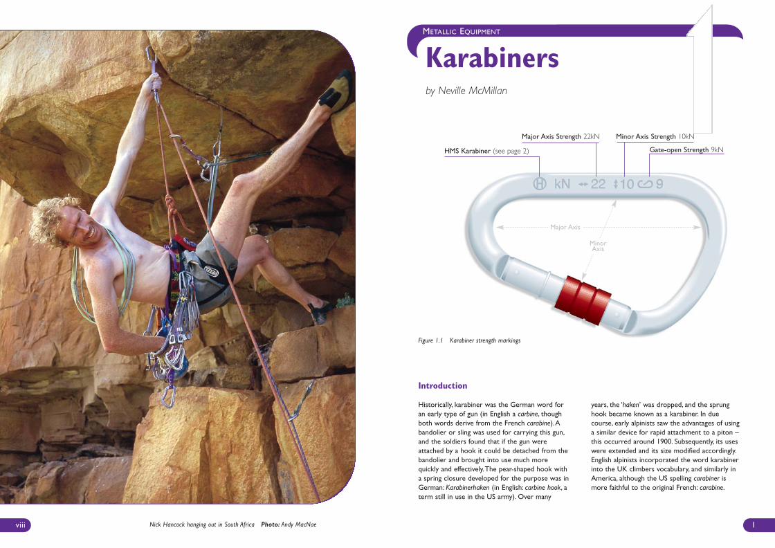
Karabinersby Neville McMillan
Introduction
Historically, karabiner was the German word foran early type of gun (in English a carbine, thoughboth words derive from the French carabine).Abandolier or sling was used for carrying this gun,and the soldiers found that if the gun wereattached by a hook it could be detached from thebandolier and brought into use much morequickly and effectively.The pear-shaped hook witha spring closure developed for the purpose was inGerman: Karabinerhaken (in English: carbine hook, aterm still in use in the US army). Over many
years, the ‘haken’ was dropped, and the sprunghook became known as a karabiner. In duecourse, early alpinists saw the advantages of usinga similar device for rapid attachment to a piton –this occurred around 1900. Subsequently, its useswere extended and its size modified accordingly.English alpinists incorporated the word karabinerinto the UK climbers vocabulary, and similarly inAmerica, although the US spelling carabiner ismore faithful to the original French: carabine.
viii
HMS Karabiner (see page 2) Gate-open Strength 9kN
Major Axis Strength 22kN Minor Axis Strength 10kN
Major Axis
Nick Hancock hanging out in South Africa Photo: Andy MacNae
Figure 1.1 Karabiner strength markings
MinorAxis
BMC Care & Maint Inside 4 1/11/07 4:01 PM Page viii
Observed faults and failures
Like all equipment, karabiners can develop faults –most of which should be apparent to the user oninspection before use.These are quite rare, andsuch faults reported to the EIP have been (oneinstance of each in the last 20 years)
• Displaced spring-pusher in the gate (causing the gate not to close)
• Loose hinge pin• Loose latch pin
There have also been some instances of seawatercorrosion due to lack of care and maintenance bythe owner (see appendix on seawater corrosion).In addition, it is known that screwgates andautolocking gates (or twistlocks) can becomeworn over time and fail to function correctly.
The majority of karabiner reports issued by theEquipment Investigation Panel (EIP) involve failuresunder load (with fatal or potentially fatal conse-quences), and were due to (most frequent first):
• Loading of the karabiner when thegate was open
• Abnormal loading of the karabiner,forcing the gate to open under load
• Loading with a sling/quickdraw (ie. no ropeinvolved) – only one instance
How to prevent failure in use
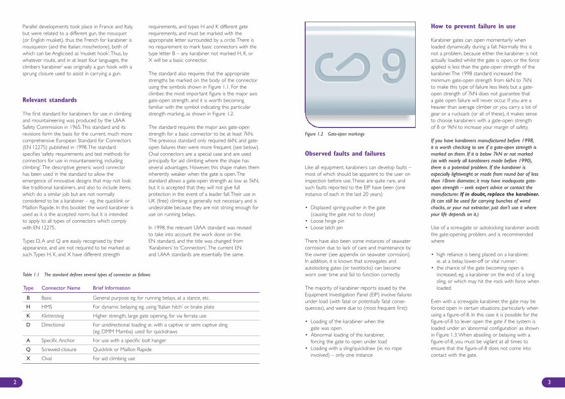
Karabiner gates can open momentarily whenloaded dynamically during a fall. Normally this isnot a problem, because either the karabiner is notactually loaded whilst the gate is open, or the forceapplied is less than the gate-open strength of thekarabiner.The 1998 standard increased theminimum gate-open strength from 6kN to 7kNto make this type of failure less likely, but a gate-open strength of 7kN does not guarantee thata gate open failure will never occur. If you are aheavier than average climber or you carry a lot ofgear or a rucksack (or all of these), it makes senseto choose karabiners with a gate-open strengthof 8 or 9kN to increase your margin of safety.
If you have karabiners manufactured before 1998,it is worth checking to see if a gate-open strength ismarked on them. If it is below 7kN or not marked(as with nearly all karabiners made before 1990),there is a potential problem. If the karabiner isespecially lightweight or made from round bar of lessthan 10mm diameter, it may have inadequate gate-open strength – seek expert advice or contact themanufacturer. If in doubt, replace the karabiner.(It can still be used for carrying bunches of wiredchocks, or your nut extractor; just don’t use it whereyour life depends on it.)
Use of a screwgate or autolocking karabiner avoidsthe gate-opening problem, and is recommendedwhere
• high reliance is being placed on a karabiner,ie. at a belay, lower-off or vital runner;
• the chance of the gate becoming open isincreased, eg. a karabiner on the end of a longsling, or which may hit the rock with force whenloaded.
Even with a screwgate karabiner, the gate may beforced open in certain situations, particularly whenusing a figure-of-8. In this case it is possible for thefigure-of-8 to lever open the gate if the system isloaded under an ‘abnormal configuration’ as shownin Figure 1.3.When abseiling or belaying with afigure-of-8, you must be vigilant at all times toensure that the figure-of-8 does not come intocontact with the gate.
3
Parallel developments took place in France and Italy,but were related to a different gun, the mousquet(or English musket), thus the French for karabiner ismousqueton (and the Italian: moschettone), both ofwhich can be Anglicised as ‘musket hook’.Thus, bywhatever route, and in at least four languages, theclimbers ‘karabiner’ was originally a gun hook with asprung closure used to assist in carrying a gun.
Relevant standards
The first standard for karabiners for use in climbingand mountaineering was produced by the UIAASafety Commission in 1965.This standard and itsrevisions form the basis for the current, much morecomprehensive European Standard for Connectors(EN 12275) published in 1998.The standardspecifies ‘safety requirements and test methods forconnectors for use in mountaineering, includingclimbing’.The descriptive generic word connectorhas been used in the standard to allow theemergence of innovative designs that may not looklike traditional karabiners, and also to include items,which do a similar job but are not normallyconsidered to be a karabiner – eg. the quicklink orMaillon Rapide. In this booklet the word karabiner isused as it is the accepted norm, but it is intendedto apply to all types of connectors which complywith EN 12275.
Types D, A and Q are easily recognised by theirappearance, and are not required to be marked assuch.Types H, K, and X have different strength
requirements, and types H and K different gaterequirements, and must be marked with theappropriate letter surrounded by a circle.There isno requirement to mark basic connectors with thetype letter B – any karabiner not marked H, K, orX will be a basic connector.
The standard also requires that the appropriatestrengths be marked on the body of the connectorusing the symbols shown in Figure 1.1. For theclimber, the most important figure is the major axisgate-open strength, and it is worth becomingfamiliar with the symbol indicating this particularstrength marking, as shown in Figure 1.2.
The standard requires the major axis gate-openstrength for a basic connector to be at least 7kN.The previous standard only required 6kN, and gate-open failures then were more frequent (see below).Oval connectors are a special case and are usedprincipally for aid climbing where the shape hasseveral advantages. However, this shape makes theminherently weaker when the gate is open.Thestandard allows a gate-open strength as low as 5kN,but it is accepted that they will not give fullprotection in the event of a leader fall.Their use inUK (free) climbing is generally not necessary, and isundesirable because they are not strong enough foruse on running belays.
In 1998, the relevant UIAA standard was revisedto take into account the work done on theEN standard, and the title was changed from‘Karabiners’ to ‘Connectors’.The current ENand UIAA standards are essentially the same.
2
Figure 1.2 Gate-open markings
Table 1.1 The standard defines several types of connector as follows:
Type Connector Name Brief Information
B Basic General purpose eg. for running belays, at a stance, etc.
H HMS For dynamic belaying eg. using ‘Italian hitch’ or brake plate
K Klettersteig Higher strength, large gate opening, for via ferrata use
D Directional For unidirectional loading ie. with a captive or semi captive sling (eg. DMM Mamba) used for quickdraws
A Specific Anchor For use with a specific bolt hanger
Q Screwed-closure Quicklink or Maillon Rapide
X Oval For aid climbing use
BMC Care & Maint Inside 4 1/11/07 4:01 PM Page 2
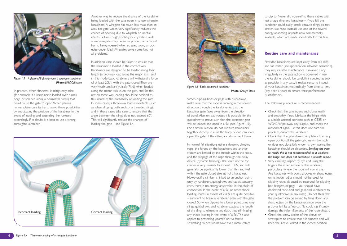
Figure 1.4 Three-way loading of screwgate karabiner
When clipping bolts or pegs with quickdraws,make sure that the rope is running in the correctdirection through the karabiner ie. that thekarabiner gate faces away from the directionof travel. Also, on slab routes it is possible for thequickdraw to move such that the karabiner gatewill be loaded and open in a fall (see Figure 1.5).For a similar reason, do not clip two karabinerstogether directly; in a fall the body of one can leveropen the gate of the other, and disconnect them.
In normal fall situations using a dynamic climbingrope, the forces on the karabiners and anchorsystem are limited by the stretch within the rope,and the slippage of the rope through the belaydevice (dynamic belaying).The force on the toprunner is very unlikely to exceed 10kN, and willgenerally be significantly lower than this and wellwithin the gate-closed strength of a karabiner.However, if a climber is linked to an anchor pointonly by karabiners, quickdraws and tape/accessorycord, there is no energy absorption in the chain ofconnection. In the event of a fall or other shockloading, forces in excess of 25kN are quite possible– sufficient to break a karabiner even with the gateclosed! So when clipping to a belay point using onlyslings, quickdraws, and karabiners, adjust the lengthof the sling to eliminate any slack, thus eliminatingany shock loading in the event of a fall.This alsoapplies to protecting yourself on via ferratascrambling routes, which have fixed metal cables
to clip to. Never clip yourself to these cables withjust a tape sling and karabiner – if you fall, thekarabiner could easily break because slings do notstretch like rope! Instead, use one of the severalenergy absorbing lanyards now commerciallyavailable, which are made specifically for this task.
Routine care and maintenance
Provided karabiners are kept away from sea cliffsand salt water (see appendix on saltwater corrosion),they require little maintenance. However, if anyirregularity in the gate action is observed in use,the karabiner should be carefully inspected as soonas possible. In any case, it makes sense to inspectall your karabiners methodically from time to time(say, once a year) to ensure their performanceis satisfactory.
The following procedure is recommended:
• Check that the gate opens and closes easilyand smoothly. If not, lubricate the hinge witha suitable aerosol lubricant such as GT85 orWD40.Wipe away any surplus, and check themovement again – if this does not cure theproblem, discard the karabiner.
• Check that the gate closes completely from anyopen position. If the gate catches on the latchor does not close fully under its own spring, thekarabiner should be discarded. Bending the gateto rectify this is not recommended as it weakensthe hinge and does not constitute a reliable repair!
• Very carefully, inspect by eye and using thefingers, the inner surface of the karabiner,particularly where the rope will run in use.Any karabiner with burrs, grooves or sharp edgeson its inside radius should not be used forclipping ropes (it could be reserved for clippingbolt hangers or pegs – you should havededicated rope-end and gear-end karabiners toyour quickdraws in any case!). Do not think thatthe problem can be solved by filing down anysharp edges on the karabiner, since even thegrooves left by a fine-cut file could significantlydamage the nylon filaments of the rope sheath.
• Check the screw action of the sleeve onscrewgates to ensure that it is smooth and willkeep the sleeve locked in the closed position.
5
In practice, other abnormal loadings may arise (for example if a karabiner is loaded over a rockedge, or scraped along a horizontal break) thatcould cause the gate to open.When placingrunners, take care to try to avoid these possibilitiesby anticipating the position of the karabiner in theevent of loading, and extending the runnersaccordingly. If in doubt, it is best to use a strongscrewgate karabiner.
Another way to reduce the chance of the karabinerbeing loaded with the gate open is to use wiregatekarabiners. A wiregate has much less mass than analloy bar gate, which very significantly reduces thechance of opening due to whiplash or inertialeffects. But on rough, knobbly, or crystalline rocksome wiregates may be more prone than a roundbar to being opened when scraped along a rockedge under load.Wiregates solve some but notall problems.
In addition, care should be taken to ensure thatthe karabiner is loaded in the correct way.Karabiners are designed to be loaded along theirlength (a two-way load along the major axis), andin this mode basic karabiners will withstand a forceof at least 20kN with the gate closed.They arevery much weaker (typically 7kN) when loadedalong the minor axis ie. on the gate, and for thisreason three-way loading should be avoided asthis increases the probability of loading the gate.In some cases, a three-way load is inevitable (suchas when clipping both ends of a threaded sling),and in these cases take care to ensure that theangle between the slings does not exceed 60º.This will significantly reduce the chances ofloading the gate – see Figure 1.4.
4
Figure 1.5 Badly-positioned karabinerPhoto: George Steele
Figure 1.3 A figure-of-8 forcing open a screwgate karabiner.Photo: BMC Collection
Incorrect loading Correct loading
BMC Care & Maint Inside 4 1/11/07 4:01 PM Page 4
7
METALLIC EQUIPMENT
Cramponsby Alan Huyton
Examine the edge of the sleeve which providesthe locking action; usually the edge which coversthe nose, but in some cases the edge whichcovers the hinge. If there is any sign of crackingor distortion, the karabiner should be discarded.
• Inspect autolocking and twistlock karabiners verycarefully – open the karabiner several times andrelease the gate from different open positions.Check that the gate closes fully every time, andthat the locking sleeve closes of its own accord. Ifthe karabiner is reluctant to lock even afterlubrication, it should be discarded. Again, checkthe edges of the sleeve – any signs of cracking ordistortion are criteria for discarding.
• If a directional karabiner (eg. DMM Mamba)includes a tape sling, inspect and maintain thesling as described in the section on slings. If thesling cannot be removed but needs replacing orre-stitching, the whole device should be returnedto the manufacturer.
• Karabiners should be stored in a dry, airy place.For quickdraws, or other connectors that havetextile elements, there is an additionalrequirement that it should be cool and dark.
Degradation and discard criteria
If properly looked after, there is no reason whya karabiner should not have a lifetime of at least20 years. Most of the discard criteria have beencovered in the routine care & maintenance sectionabove, however if the karabiner is more than tenyears old, or shows signs of corrosion or localdiscolouration, the following test should be addedto the inspection routine:
• Remove as much surface corrosion as possibleusing a domestic pan scrubber or wire wool.Carefully inspect any discoloured regions forsigns of cracking or an etched appearance on thesurface. A magnifying glass will be needed todistinguish between cracks and surface scratches.If cracks can be seen, or if the corrosion ordiscolouring are such that cracking cannot beruled out, discard the karabiner (see also thediscussion of corrosion mechanisms on page 33in the Appendix on seawater corrosion).
Provided that karabiners are properly used andlooked after, it is much more likely that they will bereplaced with new models for reasons of cosmetics,handling or strength/weight ratios than they will bediscarded over concerns about their failing strength.Nevertheless, it is important that they receivemethodical inspection and maintenance.
6
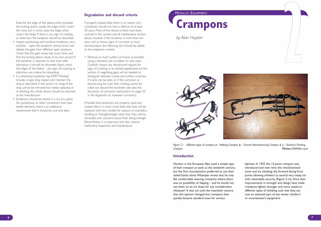
Figure 2.1 Different types of crampon: a – Walking Crampon, b – General Mountaineering Crampon & c – Technical ClimbingCrampon Photos: DMM/Ben Lyon
Introduction
Hunters in the European Alps used a simple typeof heel crampon as early as the sixteenth century,but the first mountaineers preferred to use theirnailed boots alone.Whymper wrote that he onlyfelt comfortable wearing crampons where therewas no possibility of slipping – and he would notuse them on an ice slope for any considerationwhatever! It was not until the twentieth centurythat this opinion changed but crampons thenquickly became standard issue for serious
alpinists. In 1932 the 12-point crampon wasintroduced and over time this revolutionisedsnow and ice climbing, the forward facing frontpoints allowing climbers to ascend very steep icewith reasonable security (Figure 2.1a). Since thenimprovements in strength and design have madecrampons lighter, stronger and more suited todifferent types of climbing such that they arenow an essential part of any winter climber’sor mountaineer’s equipment.
a
b
c
BMC Care & Maint Inside 4 1/11/07 4:01 PM Page 6
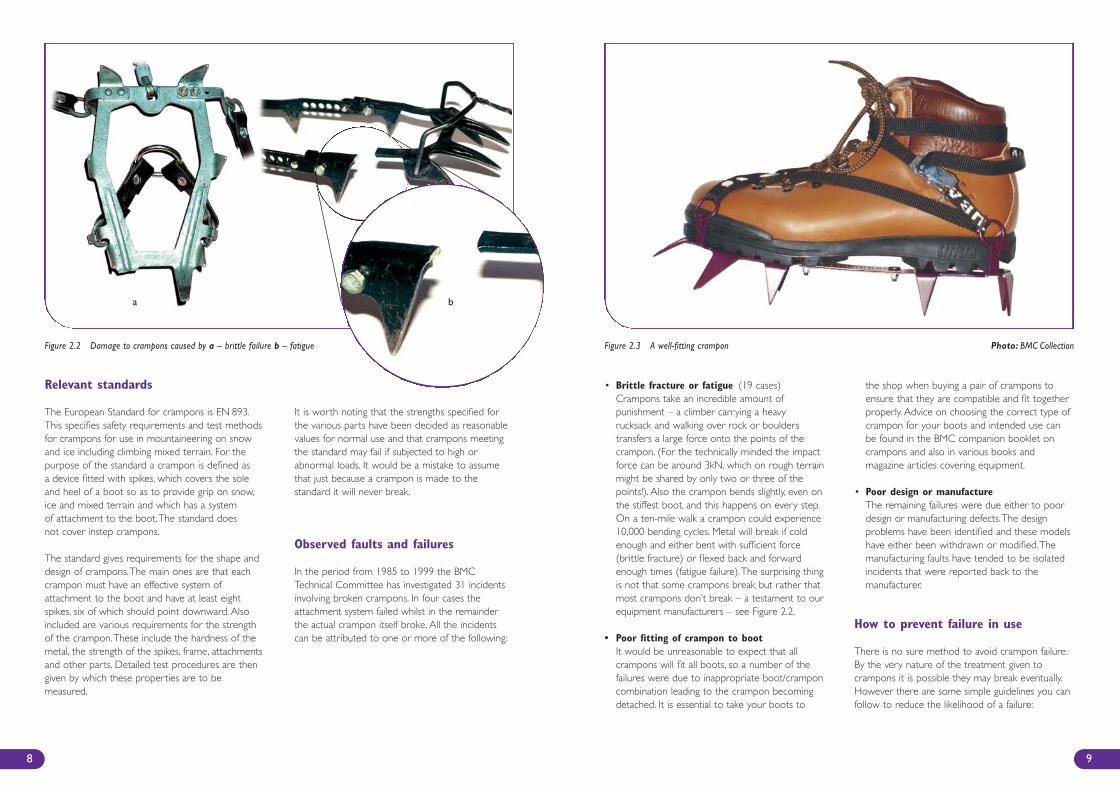
• Brittle fracture or fatigue (19 cases)Crampons take an incredible amount ofpunishment – a climber carrying a heavyrucksack and walking over rock or boulderstransfers a large force onto the points of thecrampon. (For the technically minded the impactforce can be around 3kN, which on rough terrainmight be shared by only two or three of thepoints!). Also the crampon bends slightly, even onthe stiffest boot, and this happens on every step.On a ten-mile walk a crampon could experience10,000 bending cycles. Metal will break if coldenough and either bent with sufficient force(brittle fracture) or flexed back and forwardenough times (fatigue failure).The surprising thingis not that some crampons break but rather thatmost crampons don’t break – a testament to ourequipment manufacturers – see Figure 2.2.
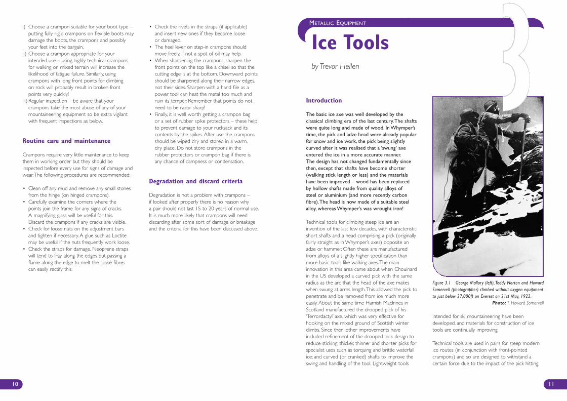
• Poor fitting of crampon to bootIt would be unreasonable to expect that allcrampons will fit all boots, so a number of thefailures were due to inappropriate boot/cramponcombination leading to the crampon becomingdetached. It is essential to take your boots to
the shop when buying a pair of crampons toensure that they are compatible and fit togetherproperly. Advice on choosing the correct type ofcrampon for your boots and intended use canbe found in the BMC companion booklet oncrampons and also in various books andmagazine articles covering equipment.
• Poor design or manufactureThe remaining failures were due either to poordesign or manufacturing defects.The designproblems have been identified and these modelshave either been withdrawn or modified.Themanufacturing faults have tended to be isolatedincidents that were reported back to themanufacturer.
How to prevent failure in use
There is no sure method to avoid crampon failure.By the very nature of the treatment given tocrampons it is possible they may break eventually.However there are some simple guidelines you canfollow to reduce the likelihood of a failure:
9
Relevant standards
The European Standard for crampons is EN 893.This specifies safety requirements and test methodsfor crampons for use in mountaineering on snowand ice including climbing mixed terrain. For thepurpose of the standard a crampon is defined asa device fitted with spikes, which covers the soleand heel of a boot so as to provide grip on snow,ice and mixed terrain and which has a systemof attachment to the boot.The standard doesnot cover instep crampons.
The standard gives requirements for the shape anddesign of crampons.The main ones are that eachcrampon must have an effective system ofattachment to the boot and have at least eightspikes, six of which should point downward. Alsoincluded are various requirements for the strengthof the crampon.These include the hardness of themetal, the strength of the spikes, frame, attachmentsand other parts. Detailed test procedures are thengiven by which these properties are to bemeasured.
It is worth noting that the strengths specified forthe various parts have been decided as reasonablevalues for normal use and that crampons meetingthe standard may fail if subjected to high orabnormal loads. It would be a mistake to assumethat just because a crampon is made to thestandard it will never break.
Observed faults and failures
In the period from 1985 to 1999 the BMCTechnical Committee has investigated 31 incidentsinvolving broken crampons. In four cases theattachment system failed whilst in the remainderthe actual crampon itself broke. All the incidentscan be attributed to one or more of the following:
8
Figure 2.2 Damage to crampons caused by a – brittle failure b – fatigue Figure 2.3 A well-fitting crampon Photo: BMC Collection
a b
BMC Care & Maint Inside 4 1/11/07 4:01 PM Page 8
Introduction
The basic ice axe was well developed by theclassical climbing era of the last century.The shaftswere quite long and made of wood. In Whymper’stime, the pick and adze head were already popularfor snow and ice work, the pick being slightlycurved after it was realised that a ‘swung’ axeentered the ice in a more accurate manner.The design has not changed fundamentally sincethen, except that shafts have become shorter(walking stick length or less) and the materialshave been improved – wood has been replacedby hollow shafts made from quality alloys ofsteel or aluminium (and more recently carbonfibre).The head is now made of a suitable steelalloy, whereas Whymper’s was wrought iron!
Technical tools for climbing steep ice are aninvention of the last few decades, with characteristicshort shafts and a head comprising a pick (originallyfairly straight as in Whymper’s axes) opposite anadze or hammer. Often these are manufacturedfrom alloys of a slightly higher specification thanmore basic tools like walking axes.The maininnovation in this area came about when Chouinardin the US developed a curved pick with the sameradius as the arc that the head of the axe makeswhen swung at arms length.This allowed the pick topenetrate and be removed from ice much moreeasily. About the same time Hamish MacInnes inScotland manufactured the drooped pick of his‘Terrordactyl’ axe, which was very effective forhooking on the mixed ground of Scottish winterclimbs. Since then, other improvements haveincluded refinement of the drooped pick design toreduce sticking; thicker, thinner and shorter picks forspecialist uses such as torquing and brittle waterfallice; and curved (or cranked) shafts to improve theswing and handling of the tool. Lightweight tools
intended for ski mountaineering have beendeveloped, and materials for construction of icetools are continually improving.
Technical tools are used in pairs for steep modernice routes (in conjunction with front-pointedcrampons) and so are designed to withstand acertain force due to the impact of the pick hitting
11
METALLIC EQUIPMENT
Ice Toolsby Trevor Hellen
i) Choose a crampon suitable for your boot type –putting fully rigid crampons on flexible boots maydamage the boots, the crampons and possiblyyour feet into the bargain.
ii) Choose a crampon appropriate for yourintended use – using highly technical cramponsfor walking on mixed terrain will increase thelikelihood of fatigue failure. Similarly, usingcrampons with long front points for climbingon rock will probably result in broken frontpoints very quickly!
iii) Regular inspection – be aware that yourcrampons take the most abuse of any of yourmountaineering equipment so be extra vigilantwith frequent inspections as below.
Routine care and maintenance
Crampons require very little maintenance to keepthem in working order but they should beinspected before every use for signs of damage andwear.The following procedures are recommended:
• Clean off any mud and remove any small stonesfrom the hinge (on hinged crampons).
• Carefully examine the corners where thepoints join the frame for any signs of cracks.A magnifying glass will be useful for this.Discard the crampons if any cracks are visible.
• Check for loose nuts on the adjustment barsand tighten if necessary. A glue such as Loctitemay be useful if the nuts frequently work loose.
• Check the straps for damage. Neoprene strapswill tend to fray along the edges but passing aflame along the edge to melt the loose fibrescan easily rectify this.
• Check the rivets in the straps (if applicable)and insert new ones if they become looseor damaged.
• The heel lever on step-in crampons shouldmove freely, if not a spot of oil may help.
• When sharpening the crampons, sharpen thefront points on the top like a chisel so that thecutting edge is at the bottom. Downward pointsshould be sharpened along their narrow edges,not their sides. Sharpen with a hand file as apower tool can heat the metal too much andruin its temper. Remember that points do notneed to be razor sharp!
• Finally, it is well worth getting a crampon bagor a set of rubber spike protectors – these helpto prevent damage to your rucksack and itscontents by the spikes. After use the cramponsshould be wiped dry and stored in a warm,dry place. Do not store crampons in therubber protectors or crampon bag if there isany chance of dampness or condensation.
Degradation and discard criteria
Degradation is not a problem with crampons –if looked after properly there is no reason whya pair should not last 15 to 20 years of normal use.It is much more likely that crampons will needdiscarding after some sort of damage or breakageand the criteria for this have been discussed above.
10
Figure 3.1 George Mallory (left),Teddy Norton and HowardSomervell (photographer) climbed without oxygen equipmentto just below 27,000ft on Everest on 21st May, 1922.
Photo: T. Howard Somervell
BMC Care & Maint Inside 4 1/11/07 4:01 PM Page 10
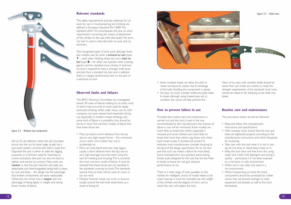
• Some modular heads can allow the pick torotate and become useless due to breakageof the bolts (holding the component in place).
• On basic ice tools, wooden shafts are quite liableto break, although using linseed-type oils tocondition the wood will help prevent this.
How to prevent failure in use
Provided that routine care and maintenance iscarried out, and the tool is used in the wayrecommended by the manufacturers, the chances offailure in use will be minimised. Some models aremore likely to break than others, especially ifmisused, and some climbers are more likely tobreak their tools than others (eg. those who climbhard mixed routes in Scotland all winter).Toreiterate: most manufacturers consider torquing tobe beyond the design specification for an ice tool,and that such use makes a failure far more likely.Some manufacturers now produce extra-strong,thicker picks designed for this use that are less likelyto break or bend, but will give reducedperformance on ice.
There is a wide range of tools available on themarket. An intelligent choice of model needs to bemade, bearing in mind the intended use, the weightof the climber, and the degree of (mis-) use towhich the user will subject the tool.
Users of ice axes with wooden shafts should beaware that such shafts are unlikely to meet thestrength requirements of the standards. Such toolscannot be relied on for belaying, as the shaft maybreak.
Routine care and maintenance
The procedures below should be followed:
• Read and follow the manufacturer’sinstructions and specifications.
• With modular tools, ensure that the nuts andbolts are tightened properly according to themanufacturers instructions, and check frequentlyfor loosening.
• Take care with the tool when it is not in use –eg. do not drop or stand heavy loads on it.
• Keep the tool clean and free from dirt, usingwater and a little mild detergent and drying itquickly – particularly if it has been exposedto a corrosive or salty environment.
• When not in use, clean and store in adry environment.
• When transporting ice tools, the sharpcomponents should be protected by rubbercovers that will prevent damage to otherequipment and people, as well as the toolsthemselves.
13
the ice.To aid adhesion when the pick has beenstruck into the ice, its lower edge usually has asaw-tooth pattern, and the pick itself is quite thin.Opposite the pick is either an adze for diggingpurposes, or a hammer used for inserting icescrews and pitons (the pick can also be used totighten and extract ice screws). Many tools aremodular, in that the pick, hammer and adze aredetachable and interchangeable, being held in placeby nuts and bolts – this design has the advantagethat broken components are easily replaceable.Otherwise, the whole tool is integral, with theadvantage of being lighter in weight and havingfewer modes of failure.
Relevant standards
The safety requirements and test methods for icetools for use in mountaineering and climbing aredefined in European Standard EN 13089.Thestandard UIAA 152 encompasses this, plus an extrarequirement concerning the means of attachmentof the climber to the axe shaft (the leash).The term‘ice tool’ is used to describe both ice axes and icehammers.
Two recognised types of tools exist, although thereare multiple uses for both: a technical ice tool (typeT – used when climbing steep ice) and a basic icetool (type B – for other use, typically when crossingglaciers and for standard snow climbs). A technicalice tool is required to have a stronger shaft, headand pick than a standard ice tool, and in additionthere is a fatigue performance test on the pick ofa technical ice tool.
Observed faults and failures
The BMC’s Technical Committee has investigatedalmost 30 cases of failures relating to ice tools, mostof which have occurred to tools used for steepice/mixed climbing, whilst under heavy use. As withcrampons, ice tools receive hard treatment duringuse (especially in modern mixed climbing), andsome kind of failure is a possibility that should beborne in mind.The common modes of failure thathave been found are:
• Picks can bend a short distance from the tipdue to very high impact forces – this commonlyoccurs when rock (rather than ice) isaccidentally hit.
• Picks can twist, bend and even snap (again,usually a short distance from the tip) due tovery high leverages incurred when using thetool for hooking and torquing.This is currentlythe most common mode of failure. It must bestressed that these forces are not specified inthe standards covering ice tools.The standardsassume that ice-tools will be used on snow orice, not rock!
• Modular hammer heads can crack or fracture,usually around the bolt hole attachment, as aresult of being hit.
12
Figure 3.2 Modular tool components
Figure 3.3 Failed axes
BMC Care & Maint Inside 4 1/11/07 4:01 PM Page 12
Introduction
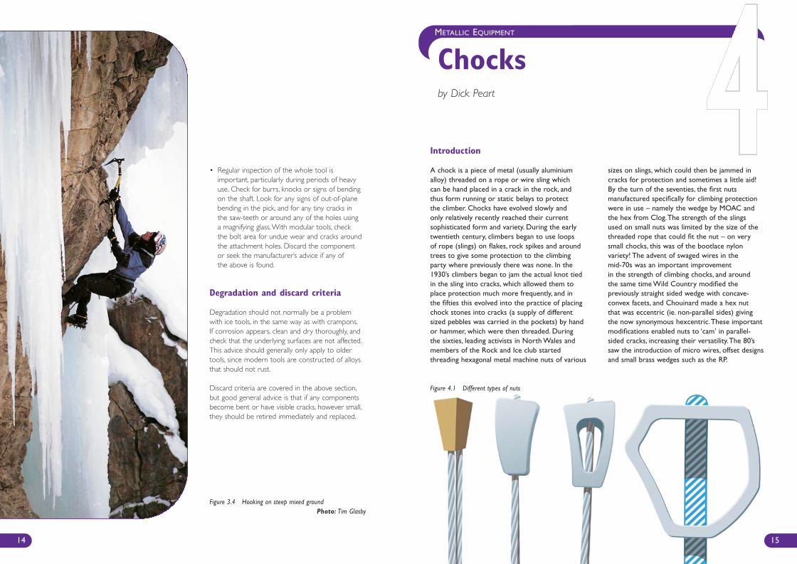
A chock is a piece of metal (usually aluminiumalloy) threaded on a rope or wire sling whichcan be hand placed in a crack in the rock, andthus form running or static belays to protectthe climber. Chocks have evolved slowly andonly relatively recently reached their currentsophisticated form and variety. During the earlytwentieth century, climbers began to use loopsof rope (slings) on flakes, rock spikes and aroundtrees to give some protection to the climbingparty where previously there was none. In the1930’s climbers began to jam the actual knot tiedin the sling into cracks, which allowed them toplace protection much more frequently, and inthe fifties this evolved into the practice of placingchock stones into cracks (a supply of differentsized pebbles was carried in the pockets) by handor hammer, which were then threaded. Duringthe sixties, leading activists in North Wales andmembers of the Rock and Ice club startedthreading hexagonal metal machine nuts of various
sizes on slings, which could then be jammed incracks for protection and sometimes a little aid!By the turn of the seventies, the first nutsmanufactured specifically for climbing protectionwere in use – namely the wedge by MOAC andthe hex from Clog.The strength of the slingsused on small nuts was limited by the size of thethreaded rope that could fit the nut – on verysmall chocks, this was of the bootlace nylonvariety! The advent of swaged wires in themid-70s was an important improvementin the strength of climbing chocks, and aroundthe same time Wild Country modified thepreviously straight sided wedge with concave-convex facets, and Chouinard made a hex nutthat was eccentric (ie. non-parallel sides) givingthe now synonymous hexcentric.These importantmodifications enabled nuts to ‘cam’ in parallel-sided cracks, increasing their versatility.The 80’ssaw the introduction of micro wires, offset designsand small brass wedges such as the RP.
METALLIC EQUIPMENT
Chocksby Dick Peart
• Regular inspection of the whole tool isimportant, particularly during periods of heavyuse. Check for burrs, knocks or signs of bendingon the shaft. Look for any signs of out-of-planebending in the pick, and for any tiny cracks inthe saw-teeth or around any of the holes usinga magnifying glass.With modular tools, checkthe bolt area for undue wear and cracks aroundthe attachment holes. Discard the componentor seek the manufacturer’s advice if any ofthe above is found.
Degradation and discard criteria
Degradation should not normally be a problemwith ice tools, in the same way as with crampons.If corrosion appears, clean and dry thoroughly, andcheck that the underlying surfaces are not affected.This advice should generally only apply to oldertools, since modern tools are constructed of alloysthat should not rust.
Discard criteria are covered in the above section,but good general advice is that if any componentsbecome bent or have visible cracks, however small,they should be retired immediately and replaced.
Figure 3.4 Hooking on steep mixed groundPhoto: Tim Glasby
14 15
Figure 4.1 Different types of nuts
BMC Care & Maint Inside 4 1/11/07 4:01 PM Page 14
How to prevent failure in use
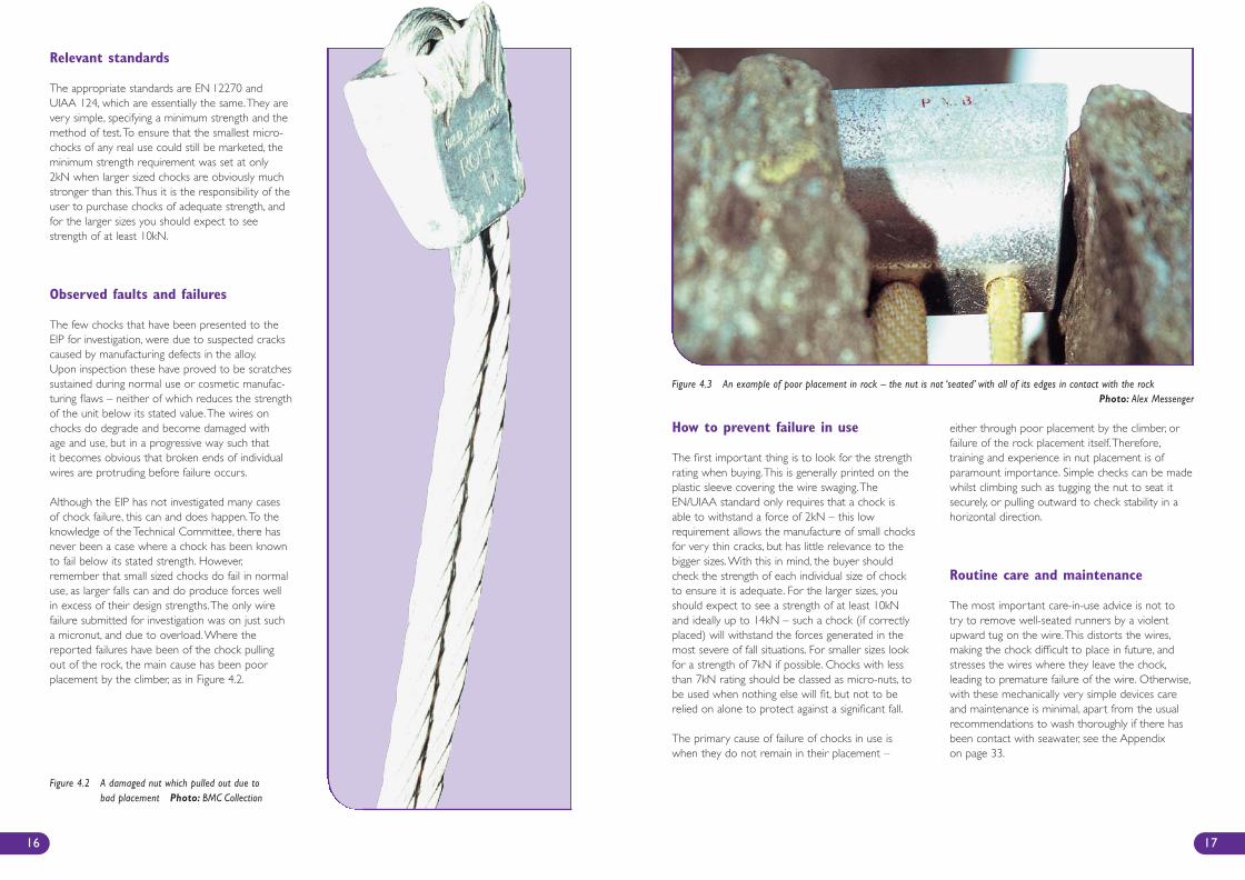
The first important thing is to look for the strengthrating when buying.This is generally printed on theplastic sleeve covering the wire swaging.TheEN/UIAA standard only requires that a chock isable to withstand a force of 2kN – this lowrequirement allows the manufacture of small chocksfor very thin cracks, but has little relevance to thebigger sizes.With this in mind, the buyer shouldcheck the strength of each individual size of chockto ensure it is adequate. For the larger sizes, youshould expect to see a strength of at least 10kNand ideally up to 14kN – such a chock (if correctlyplaced) will withstand the forces generated in themost severe of fall situations. For smaller sizes lookfor a strength of 7kN if possible. Chocks with lessthan 7kN rating should be classed as micro-nuts, tobe used when nothing else will fit, but not to berelied on alone to protect against a significant fall.
The primary cause of failure of chocks in use iswhen they do not remain in their placement –
either through poor placement by the climber, orfailure of the rock placement itself.Therefore,training and experience in nut placement is ofparamount importance. Simple checks can be madewhilst climbing such as tugging the nut to seat itsecurely, or pulling outward to check stability in ahorizontal direction.
Routine care and maintenance
The most important care-in-use advice is not totry to remove well-seated runners by a violentupward tug on the wire.This distorts the wires,making the chock difficult to place in future, andstresses the wires where they leave the chock,leading to premature failure of the wire. Otherwise,with these mechanically very simple devices careand maintenance is minimal, apart from the usualrecommendations to wash thoroughly if there hasbeen contact with seawater, see the Appendixon page 33.
17
Relevant standards
The appropriate standards are EN 12270 andUIAA 124, which are essentially the same.They arevery simple, specifying a minimum strength and themethod of test.To ensure that the smallest micro-chocks of any real use could still be marketed, theminimum strength requirement was set at only2kN when larger sized chocks are obviously muchstronger than this.Thus it is the responsibility of theuser to purchase chocks of adequate strength, andfor the larger sizes you should expect to seestrength of at least 10kN.
Observed faults and failures
The few chocks that have been presented to theEIP for investigation, were due to suspected crackscaused by manufacturing defects in the alloy.Upon inspection these have proved to be scratchessustained during normal use or cosmetic manufac-turing flaws – neither of which reduces the strengthof the unit below its stated value.The wires onchocks do degrade and become damaged withage and use, but in a progressive way such thatit becomes obvious that broken ends of individualwires are protruding before failure occurs.
Although the EIP has not investigated many casesof chock failure, this can and does happen.To theknowledge of the Technical Committee, there hasnever been a case where a chock has been knownto fail below its stated strength. However,remember that small sized chocks do fail in normaluse, as larger falls can and do produce forces wellin excess of their design strengths.The only wirefailure submitted for investigation was on just sucha micronut, and due to overload.Where thereported failures have been of the chock pullingout of the rock, the main cause has been poorplacement by the climber, as in Figure 4.2.
16
Figure 4.2 A damaged nut which pulled out due tobad placement Photo: BMC Collection
Figure 4.3 An example of poor placement in rock – the nut is not ‘seated’ with all of its edges in contact with the rockPhoto: Alex Messenger
BMC Care & Maint Inside 4 1/11/07 4:01 PM Page 16

19
METALLIC EQUIPMENT
Camming Devicesby Alan Huyton
Introduction
Camming devices for climbing were firstdeveloped in the early seventies by Greg Loweas a method of protecting the long, mildly flaringcracks of Yosemite Valley.They subsequentlyrevolutionised climbing the world over by enablingmany previously unprotectable climbs to beascended safely.The early devices had to beremoved by reaching a hand into the crack torotate the cams, but a few years later Ray Jardine
made a four-cam unit with a trigger bar, whichis the basis of the designs used today.The mostsignificant refinement of this design was theintroduction of flexible stemmed units, allowingcamming devices to be placed in horizontal breakswithout the need to tie off the rigid stem, orrisking its breakage. More recent developmentsinclude offset or different-sized cams, and extrasmall units to fit very thin cracks.
• Cord or tape used to thread nuts should beshifted through the nut at regular intervals tospread the wear, and replaced when it becomesdiscoloured or shows signs of wear, or aftera particularly serious fall. Check any knotsfrequently for slippage.
• ‘Slide’ nuts on swaged wires so that the wirenormally hidden by the body of the chock maybe visually checked.
• Chocks should be stored in a dry airy place.If they are on cord or tape, it should also becool and dark.
Degradation and discard criteria
Apart from corrosion, damage to the chock itselfwill only occur either by excessive hammering toremove it from the rock, or damage if the chock ispulled out of the rock during a fall. Both are likelyto be more serious for a small chock. Any significantchange in the shape of the chock is an obviousdiscard criterion.
A more likely area of concern is the wire – theseshould be inspected regularly, particularly aroundthe areas where the wire emerges from the nut. Ifthere is any sign of corrosion, damage or breakageof wire strands, the nut should be discarded.
18
Figure 5.1 Peter Robbins in South Africa Photo: Andy MacNae
BMC Care & Maint Inside 4 1/11/07 4:01 PM Page 18
• In horizontal placements ensure the stem touchesthe lower rock edge as mentioned above.
• Try to avoid using devices with rigid stems inhorizontal cracks; flexible stem units are moresuited to these placements. If a rigid device mustbe used consider tying off the stem close to therock to reduce the leverage on the stem.
• Excessive movement of the rope can cause thesedevices to move about in the crack (walking).Be aware of this and try to choose a placementwhere the crack does not get wider or the unitmay move and fall out. A longer extension slingcan sometimes help to prevent this or anotherrunner close by can have the same effect.
• Some camming devices have strong cam stopswhich are designed to hold a fall if the cams arefully open (in which case the device behaves asa chock, and camming action ceases), but manyof the older models do not. Make sure you knowthe difference and if in doubt do not rely onthem holding if fully open.
• Try not to place them deeply in cracks or inawkward positions as your second will havetrouble removing them and they are tooexpensive to abandon!
• Ensure that the unit operates smoothly and theaxle is lubricated (see section on Care andMaintenance).This is essential for correctoperation in the event of a fall as well as easeof placement and removal.
Routine care and maintenance
Camming devices are fairly complex mechanismsand as such are not easily maintained. In the eventof damage due to a serious fall or general wear andtear they should be returned to the manufacturerfor maintenance. Most manufacturers offer thisservice but it should be realised that they may notbe able to maintain the older models since theymay no longer make the parts or the unit may beso worn or damaged that they cannot bring it backto the standard they set for their equipment.Theuser should regularly inspect and service the unitas detailed below:
• Ensure that the unit is clean and free from dirtor grit, particularly around the axle and betweenthe cams. Remove with a soft brush (an oldtoothbrush, for example) using clean warm waterand mild detergent. Rinse in clean water andallow to dry in a warm room.
• Check that the cams and trigger operatesmoothly through their full range of movementand that the cams return to the fully openposition when the trigger is released. Lubricateperiodically and also after any cleaning with anaerosol lubricant such as GT85 or WD40,which should be sprayed between the camsand on the axle.Wipe off any surplus and avoidallowing it to contaminate the textile sling.
21
Relevant standards
The European Standard for spring loaded cammingdevices (SLCDs) is EN 12276 and this covers alltypes of adjustable chocks that rely on friction andwill therefore work in parallel-sided cracks. Hencethe standard applies to sliding nuts as well as thevarious types of SLCDs.The standard specifies atest rig consisting of two parallel steel plates to holdthe cams and a loading bar.The force required tocause the unit to break or slip through the testapparatus should be at least 5kN. In addition thestandard specifies the information which must beprovided with the device, which includes aminimum guaranteed holding force (equal to orgreater than 5kN).There are two important pointsto note about this standard:
1. The reason the tests are carried out using steelplates rather than rock is because this can bemade repeatable between the various testlaboratories. SLCDs rely on friction to keep themin place during a fall and there are certainsituations when the friction available will be lessthan in the test, for example – wet, icy or sandyrock, lichen covered rock and rock with a softsurface layer. Most camming devices have teethon the cams so they will hopefully bite throughany surface layer to the solid rock underneath.
2. The strength quoted is in an ideal situationwhere the unit is loaded along its axis with thecams open equally on each side. In some realfalls this is not the case and so the strengthof the unit will be less than quoted.The 5kNspecified in the standard is a minimum forthe smaller units and it is known that this canbe exceeded in long falls.Therefore it isrecommended that larger units with strengthsof 10kN or more should be used whereverpossible.
There is also a UIAA standard No.125 whichis closely based on EN 12276 but which hasadditional requirements concerning the stitchingof the textile sling.
Observed faults and failures
Since 1988 the BMC Technical Committee hasinvestigated 8 incidents involving frictional anchors,7 of which were SLCDs. In all cases where thedevice broke it was concluded that the cause wasdue to poor placement.The BMC TechnicalCommittee believes that if placed correctly andif the device does not rip out of the crack(which is just another form of poor placement)then camming devices are quite strong enoughto hold most falls.
How to prevent failure in use
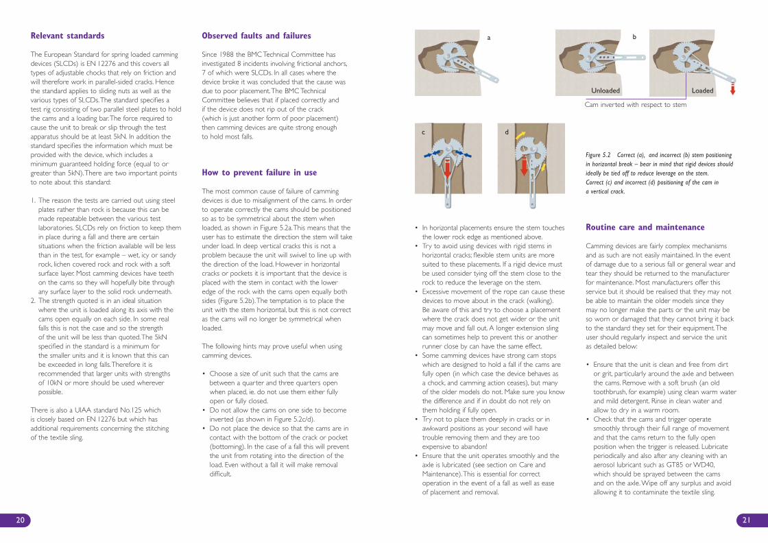
The most common cause of failure of cammingdevices is due to misalignment of the cams. In orderto operate correctly the cams should be positionedso as to be symmetrical about the stem whenloaded, as shown in Figure 5.2a.This means that theuser has to estimate the direction the stem will takeunder load. In deep vertical cracks this is not aproblem because the unit will swivel to line up withthe direction of the load. However in horizontalcracks or pockets it is important that the device isplaced with the stem in contact with the loweredge of the rock with the cams open equally bothsides (Figure 5.2b).The temptation is to place theunit with the stem horizontal, but this is not correctas the cams will no longer be symmetrical whenloaded.
The following hints may prove useful when usingcamming devices.
• Choose a size of unit such that the cams arebetween a quarter and three quarters openwhen placed, ie. do not use them either fullyopen or fully closed.
• Do not allow the cams on one side to becomeinverted (as shown in Figure 5.2c/d).
• Do not place the device so that the cams are incontact with the bottom of the crack or pocket(bottoming). In the case of a fall this will preventthe unit from rotating into the direction of theload. Even without a fall it will make removaldifficult.
20
Figure 5.2 Correct (a), and incorrect (b) stem positioningin horizontal break – bear in mind that rigid devices shouldideally be tied off to reduce leverage on the stem.Correct (c) and incorrect (d) positioning of the cam ina vertical crack.
a b
c d
Cam inverted with respect to stem
LoadedUnloaded
BMC Care & Maint Inside 4 1/11/07 4:01 PM Page 20
23
METALLIC EQUIPMENT
Ascendersby Ben Lyon
• Examine the metal parts for any cracks ordeformation and the wires for any brokenstrands. If any of these are found the unitshould either be discarded or repaired by themanufacturer. Bent wires or flexible stems cansometimes be carefully straightened by handor replaced by the manufacturer.
• Textile slings should be checked for wear andbroken stitching and replaced if necessary.When cleaning and drying make sure slingsare kept below 50°C.
SeawaterSee separate section on seawater corrosionof metallic climbing equipment.
Transport and StorageWhen carrying cams in a rucksack it is worthpacking them carefully to avoid bending the triggerwires. For prolonged storage they should be keptsomewhere dry.
Degradation and discard criteria
Of all the metallic gear on a climbers rack thecamming devices are likely to wear out first.Thisseems particularly unfair since they are also themost expensive! The reason is simple – complexmechanisms with lots of moving parts areexpensive to make and moving parts wear out.With average use, without serious falls andprovided the routine care and maintenancedescribed earlier is carried out most cammingdevices should last 10 years.They should bediscarded if they no longer operate smoothlyor if they are cracked or damaged as describedin the section on care and maintenance.
22
Figure 5.3 Example of a camming unit with a failed triggerwire. It is important to check the trigger wires for brokenstrands. Manufacturers will repair damaged trigger wires,which helps to avoid the situation shown left.
Photo: BMC Collection
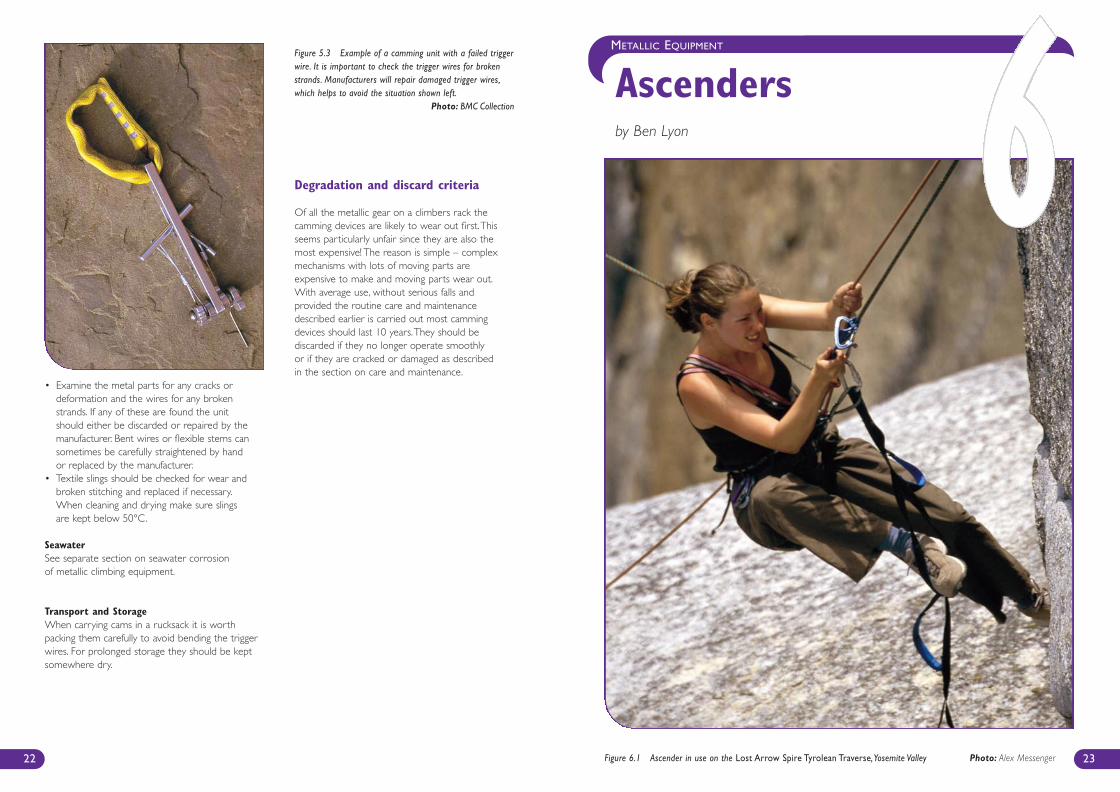
Figure 6.1 Ascender in use on the Lost Arrow Spire Tyrolean Traverse,Yosemite Valley Photo: Alex Messenger
BMC Care & Maint Inside 4 1/11/07 4:02 PM Page 22
25
Introduction
Ascenders are described as devices that whenaffixed to a rope, will slide or lock as required.Most (but not all) will lock in one direction only.The first ascenders were effectively the humanhand and foot, but straightforward gripping isdifficult on ropes of climbing diameter! The firstmechanical device employed as an ascender wasthe Prusik knot – a closed loop of lesser diametercord is wrapped at least twice around the ropeand tucked through itself.The knot so formed willslide if pushed upwards by hand, but lock if pulleddownward by the main loop. Derivatives ofthe Prusik knot such as the Bachmann knotincorporate a karabiner, and slide more easilywhilst providing a handle (the karabiner) forease of use.This type of knot is generally usedin improvised situations, and has become lesscommon with the advent of mechanical ascenders,which are commonly used in climbing andmountaineering situations where climbingof the rope is intended.
Most mechanical ascenders are quite large(sometimes handled) devices as in Figure 6.3,and work by trapping the rope between a cam(an eccentrically mounted rotating body) anda housing body.These can be subdivided intoascenders which are loaded via the body (most ofwhich have toothed cams to grip the rope) andthose that are loaded via the cam itself by a leverextension.The latter usually have a less aggressivecam surface presented to the rope.The latestascender on the market (and the third typeavailable) is a lightweight ‘emergency’ type clampwith no moving parts at all, that removes much ofthe bulk generally associated with ascendingdevices.
Since most failures associated with ascenders aredue to inappropriate usage the various types ofascender and their intended uses are nowdiscussed:
For individuals climbing clean ropes, body-loadedascenders are usually more efficient.They tend tobe easier to put onto the rope, and allow all theclimber’s effort to be translated into upwardmovement.There are handled, non-handled and
chest-mounting body-loaded ascenders available;so make sure you buy the right type for thetechnique you will be using. Be aware that body-loaded ascenders require aggressively toothed camsto grip the rope, so that sheath damage will occurif they are overloaded, and this type of ascenderwill wear your rope more quickly than a camloaded type. Also, the open channel constructionrequired for rope entry means that the ascenderitself may begin to open under excessive load.
If using an ascender in a situation where high loadsmay occur (eg. tensioning ropes in rescuesituations), a cam-loaded ascender may be preferred.These are usually more fiddly to attach to the rope,but complete mechanical enclosure of the ropegives added strength and security.The lever effectthat they exert distorts the passage of the rope, butthis means that they exert less pressure on therope whilst giving the same level of grip, and thatwearing of the rope is less than with body-loadedascenders.Thus, they are less likely to slip on icyor muddy ropes, but the action of the lever meansthat there is less height gain for each reach/stepupwards.
Thirdly, very small ‘emergency’ ascenders with nomoving parts at all are now available.These areinvaluable in emergency situations or for occasionaluse, but must be used with care and should not beregarded as suitable for regular and repeated use.
Relevant standards
The European Standard is EN 567: MountaineeringEquipment – Rope Clamps, and the technicalrequirement of the UIAA standard is identical. Keyrequirements of the standards are:
• marking of the clamp with the range of ropediameters which may be used;
• requiring the clamp to hold to 4kN withoutsignificant visible deformation to the rope andwithout it breaking;
• that the clamp should have a locking device toprevent the rope becoming detached.
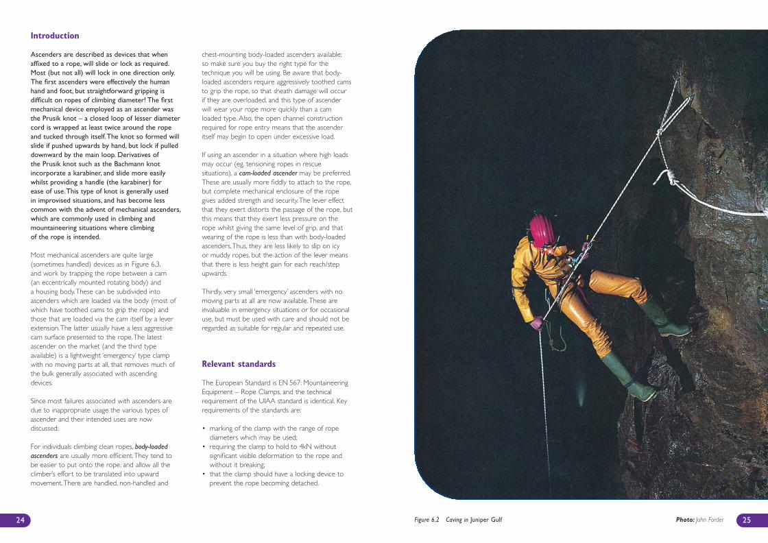
24 Figure 6.2 Caving in Juniper Gulf Photo: John Forder
BMC Care & Maint Inside 4 1/11/07 4:02 PM Page 24
It is important to realise that all ascenders exerta very high pinching load on the rope, and somemore than others – in general, ascenders loadedvia the retaining body exert a higher force thanthose loaded via the cam.
As a general rule, ascenders should only be usedto hold the static load of one person.They shouldnever be relied upon to hold the fully loadedsection of a tyrolean traverse, nor be relied uponto hold any kind of dynamic fall.
Routine care and maintenance
Ascenders will benefit from regular care andmaintenance from the user.The following actionsare recommended:
• Read and follow the manufacturer’s instructions,and only use the ascender according to these.
• In general, care for as for any other metallicclimbing equipment, so:– do not drop, or allow heavy loads to be
dropped on the ascender;– after use, clean with water if necessary and
dry ASAP – use an old toothbrush on dirtycams and locking mechanisms (this should bedone as soon as is practical after exposure tosalt water – see Appendix Section 1);
– disinfect following the manufacturer’sinstructions.
• Inspect before and after each use, checkingparticularly:– that any spring actions are working correctly;– that the cam surface and teeth are not worn
out or corroded;– that the body of the ascender is not
appreciably worn or corroded;– that all axles are secure;– that the locking mechanism is working
properly, and its action is smooth;– check the whole piece for cracks and wear.
• Store in a dry place.• There are no special transport requirements.
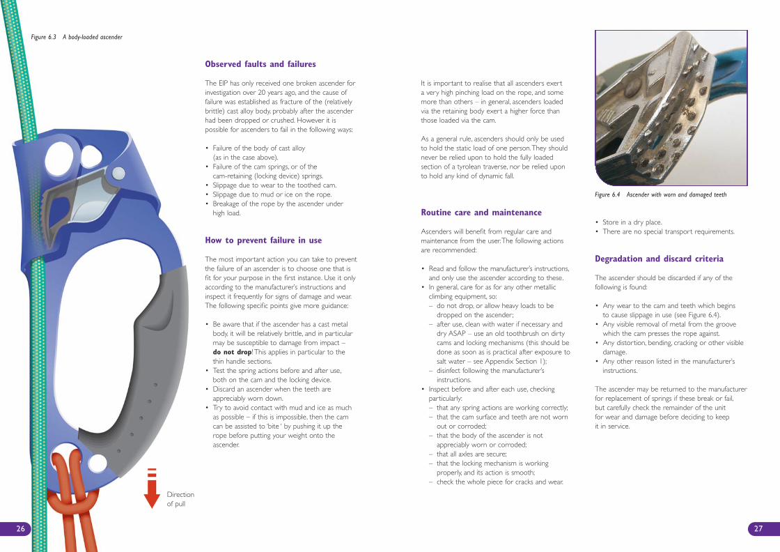
Degradation and discard criteria
The ascender should be discarded if any of thefollowing is found:
• Any wear to the cam and teeth which beginsto cause slippage in use (see Figure 6.4).
• Any visible removal of metal from the groovewhich the cam presses the rope against.
• Any distortion, bending, cracking or other visibledamage.
• Any other reason listed in the manufacturer’sinstructions.
The ascender may be returned to the manufacturerfor replacement of springs if these break or fail,but carefully check the remainder of the unitfor wear and damage before deciding to keepit in service.
27
Observed faults and failures
The EIP has only received one broken ascender forinvestigation over 20 years ago, and the cause offailure was established as fracture of the (relativelybrittle) cast alloy body, probably after the ascenderhad been dropped or crushed. However it ispossible for ascenders to fail in the following ways:
• Failure of the body of cast alloy (as in the case above).
• Failure of the cam springs, or of thecam-retaining (locking device) springs.
• Slippage due to wear to the toothed cam.• Slippage due to mud or ice on the rope.• Breakage of the rope by the ascender under
high load.
How to prevent failure in use
The most important action you can take to preventthe failure of an ascender is to choose one that isfit for your purpose in the first instance. Use it onlyaccording to the manufacturer’s instructions andinspect it frequently for signs of damage and wear.The following specific points give more guidance:
• Be aware that if the ascender has a cast metalbody, it will be relatively brittle, and in particularmay be susceptible to damage from impact –do not drop! This applies in particular to thethin handle sections.
• Test the spring actions before and after use,both on the cam and the locking device.
• Discard an ascender when the teeth areappreciably worn down.
• Try to avoid contact with mud and ice as muchas possible – if this is impossible, then the camcan be assisted to ‘bite ‘ by pushing it up therope before putting your weight onto theascender.
Figure 6.3 A body-loaded ascender
Figure 6.4 Ascender with worn and damaged teeth
26
Directionof pull
BMC Care & Maint Inside 4 1/11/07 4:02 PM Page 26
29
METALLIC EQUIPMENT
Belaying & Abseiling devicesby Ben Lyon
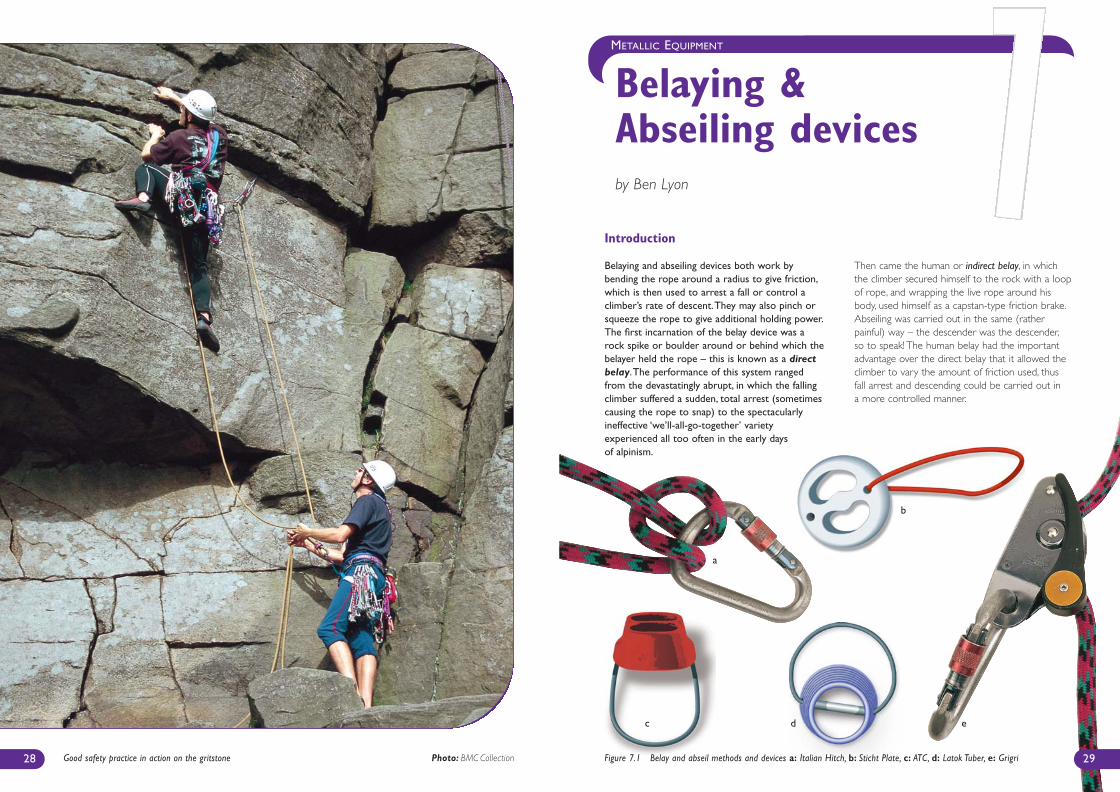
28 Good safety practice in action on the gritstone Photo: BMC Collection Figure 7.1 Belay and abseil methods and devices a: Italian Hitch, b: Sticht Plate, c: ATC, d: Latok Tuber, e: Grigri
a
b
c d e
Introduction
Belaying and abseiling devices both work bybending the rope around a radius to give friction,which is then used to arrest a fall or control aclimber’s rate of descent.They may also pinch orsqueeze the rope to give additional holding power.The first incarnation of the belay device was arock spike or boulder around or behind which thebelayer held the rope – this is known as a directbelay.The performance of this system rangedfrom the devastatingly abrupt, in which the fallingclimber suffered a sudden, total arrest (sometimescausing the rope to snap) to the spectacularlyineffective ‘we’ll-all-go-together’ varietyexperienced all too often in the early daysof alpinism.
Then came the human or indirect belay, in whichthe climber secured himself to the rock with a loopof rope, and wrapping the live rope around hisbody, used himself as a capstan-type friction brake.Abseiling was carried out in the same (ratherpainful) way – the descender was the descender,so to speak! The human belay had the importantadvantage over the direct belay that it allowed theclimber to vary the amount of friction used, thusfall arrest and descending could be carried out ina more controlled manner.
BMC Care & Maint Inside 4 1/11/07 4:02 PM Page 28
The important consideration when selecting adevice is that it is fit for purpose: ask yourselfthe following questions:
• Does it need to work on one rope or two?• Is it suitable for the diameter of rope to be used?• Does it provide enough friction for you to
control it effectively? Does it operate smoothlyor tend to ‘grab’ and lock under sudden load?
• Will you use it for both belaying and abseiling?• Do you have the necessary skills for its safe use?
Observed faults and failures
The Technical Committee is aware of numerouscases of failures within belaying or abseiling systems,but be aware that the system includes the userand that very few, if any of these failures can beattributed to the actual device in use. Belay andabseil devices are very much a part of a systemand do not work by themselves, but in conjunctionwith karabiners, ropes and most importantlyclimbers. Common causes of system failure include:
• misusing locking devices, preventing theirproper action;
• inserting the rope/s wrongly into the device;• using the wrong diameter of rope;• using double ropes of differing diameters
in double rope devices (resulting in differingamounts of friction between the two ropes);
• incorrect alignment of the device andconnecting karabiner ;
• insufficient strength/skill or care and attentionof the belayer/abseiler (may be due to tiredness,cold or distraction);
• poor or inattentive holding technique;• allowing the device to provide too little friction,
resulting in the rope travelling through the devicetoo quickly (or even freely), possibly resulting inburned hands and releasing of the rope;
• clothing or hair becoming jammed in the device;• relying totally on a locking mechanism, or using it
as a ‘hands-free’ device;• adopting a poor belaying stance (eg. standing
precariously balanced, sitting or lying down orstanding too far away from the rock), resultingin stumbling or slipping in the event of a falland releasing the device.
31
The first modern belay device was probablyconstructed from two (or four) karabiners placedat 90º to each other, with the rope forming a loopover and under the bar of one of the karabiners.Another common early form of this dynamic belaywas the use of an Italian hitch tied on a karabinerwith a wide nose profile (pear-shaped). Both ofthese methods can still be usefully employed today.
Nowadays, belay and abseil devices come in manyshapes and sizes (Figure 7.1), but are all basicallymetal devices through which the rope runs, with avarying amount of friction and/or pinching, allowinga high force on the exit side to be controlled byexerting a lower force on the entry side.The onlyfundamental difference between a belay and abseildevice is the way in which they are used – a belaydevice is held static whilst the rope runs through it,whereas an abseil device slides down a static line.Thus, as far as the bit of metal forming the device isconcerned, the distinction is rather academic –abseil devices can in theory (and often in practice)be used as belay devices and vice versa. Currentlyavailable designs fall into one of four categories.
• Flat plate (such as sticht plate)A basic circular plate with holes through whichthe rope is fed; when used in conjunction witha karabiner this bends the rope through twodimensions.When actioned by the belayer,it provides both frictional and pinching effectsand ‘grabs’ the rope.This tendency can be both
a help and a hindrance.There are many designvariations, providing various relative degreesof friction and pinching, and hence differing easeof use. In all cases the principle is the same.
• Tube devices (such as ATC or Tuber)A short tube through which the rope is fed. Aswith the flat plate, it is used with a karabiner andbends the rope in two dimensions. Unlike the flatplate, it does not pinch the rope, but reliesinstead on friction.These devices arecharacterised by relative ease of use and ‘slick’feed, but the lack of a pinching action increasesreliance on the strength and skill of the belayer.
• Figure-of-8 This design bends the rope through3 dimensions to create friction, and with thesedevices the karabiner is required only to provideattachment to the climber’s harness, not toprovide friction. Again, many variations exist,but all are characterised by a high degree of‘slickness’ in use.
• Locking devicesThese have the advantage that a climber canbe held on the rope for long periods of timewithout the belayer needing to maintain tensionon the live rope, and most will lock quickly inthe event of a fall. However, they are not infallibleand require skill and vigilance from the userto perform correctly.They are often of a morecomplicated design and may contain movingparts, so their care and maintenance becomesmore of an issue.
Relevant standards
There are no current standards for belaying andabseiling devices for mountaineering and climbing –at present the UIAA Safety Commission is workingto produce one.There is a European Standard(EN 341) for descenders, which defines these unitsas ‘rescue devices’, and is intended to describeparameters for lowering people to safety via a ropeand descender. Unlike most other items of metallicclimbing equipment, belay and abseil devices havenot been classified as Personal ProtectiveEquipment (PPE), and hence do not carry a CEmark.This situation may well change in the nearfuture. A few abseil devices used for climbing havebeen certified to EN 341, but when looking for theright buy, you should not be influenced for oragainst on the basis of conformity to this standard.
30
Figure 7.2 Abseiling under instructionPhoto: BMC Collection
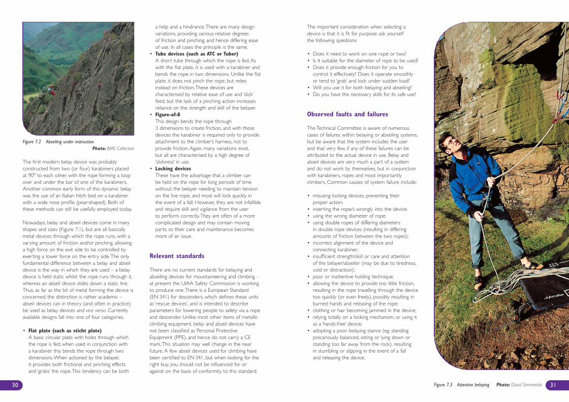
Figure 7.3 Attentive belaying Photo: David Simmonite
BMC Care & Maint Inside 4 1/11/07 4:02 PM Page 30
33
METALLIC EQUIPMENT
1. Seawater Corrosion
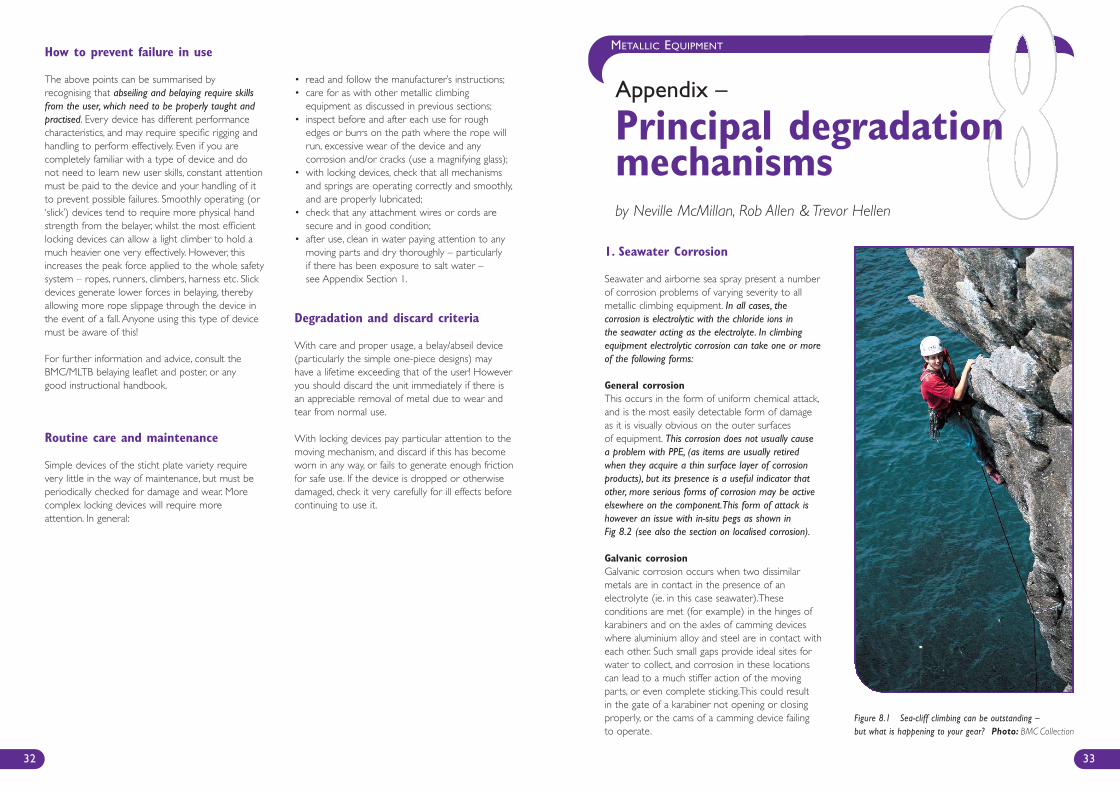
Seawater and airborne sea spray present a numberof corrosion problems of varying severity to allmetallic climbing equipment. In all cases, thecorrosion is electrolytic with the chloride ions in the seawater acting as the electrolyte. In climbingequipment electrolytic corrosion can take one or moreof the following forms:
General corrosionThis occurs in the form of uniform chemical attack,and is the most easily detectable form of damage as it is visually obvious on the outer surfaces of equipment. This corrosion does not usually cause a problem with PPE, (as items are usually retiredwhen they acquire a thin surface layer of corrosionproducts), but its presence is a useful indicator thatother, more serious forms of corrosion may be activeelsewhere on the component.This form of attack ishowever an issue with in-situ pegs as shown in Fig 8.2 (see also the section on localised corrosion).
Galvanic corrosion Galvanic corrosion occurs when two dissimilarmetals are in contact in the presence of anelectrolyte (ie. in this case seawater).Theseconditions are met (for example) in the hinges ofkarabiners and on the axles of camming deviceswhere aluminium alloy and steel are in contact witheach other. Such small gaps provide ideal sites forwater to collect, and corrosion in these locationscan lead to a much stiffer action of the movingparts, or even complete sticking.This could result in the gate of a karabiner not opening or closingproperly, or the cams of a camming device failing to operate.
How to prevent failure in use
The above points can be summarised byrecognising that abseiling and belaying require skillsfrom the user, which need to be properly taught andpractised. Every device has different performancecharacteristics, and may require specific rigging andhandling to perform effectively. Even if you arecompletely familiar with a type of device and donot need to learn new user skills, constant attentionmust be paid to the device and your handling of itto prevent possible failures. Smoothly operating (or‘slick’) devices tend to require more physical handstrength from the belayer, whilst the most efficientlocking devices can allow a light climber to hold amuch heavier one very effectively. However, thisincreases the peak force applied to the whole safetysystem – ropes, runners, climbers, harness etc. Slickdevices generate lower forces in belaying, therebyallowing more rope slippage through the device inthe event of a fall. Anyone using this type of devicemust be aware of this!
For further information and advice, consult theBMC/MLTB belaying leaflet and poster, or anygood instructional handbook.
Routine care and maintenance
Simple devices of the sticht plate variety requirevery little in the way of maintenance, but must beperiodically checked for damage and wear. Morecomplex locking devices will require moreattention. In general:
• read and follow the manufacturer’s instructions;• care for as with other metallic climbing
equipment as discussed in previous sections;• inspect before and after each use for rough
edges or burrs on the path where the rope willrun, excessive wear of the device and anycorrosion and/or cracks (use a magnifying glass);
• with locking devices, check that all mechanismsand springs are operating correctly and smoothly,and are properly lubricated;
• check that any attachment wires or cords aresecure and in good condition;
• after use, clean in water paying attention to anymoving parts and dry thoroughly – particularlyif there has been exposure to salt water –see Appendix Section 1.
Degradation and discard criteria
With care and proper usage, a belay/abseil device(particularly the simple one-piece designs) mayhave a lifetime exceeding that of the user! Howeveryou should discard the unit immediately if there isan appreciable removal of metal due to wear andtear from normal use.
With locking devices pay particular attention to themoving mechanism, and discard if this has becomeworn in any way, or fails to generate enough frictionfor safe use. If the device is dropped or otherwisedamaged, check it very carefully for ill effects beforecontinuing to use it.
32
Figure 8.1 Sea-cliff climbing can be outstanding – but what is happening to your gear? Photo: BMC Collection
Appendix –
Principal degradationmechanismsby Neville McMillan, Rob Allen & Trevor Hellen
239B - BMC Care & Maint Inside 3/28/07 2:25 PM Page 32
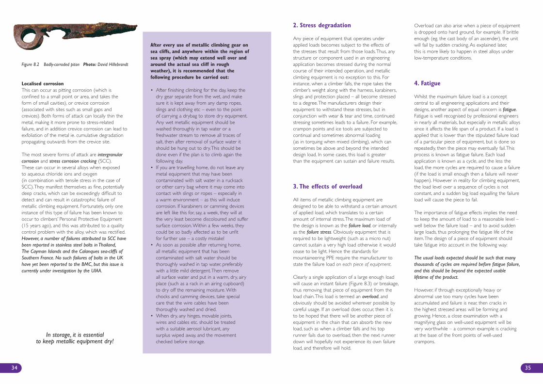
2. Stress degradation
Any piece of equipment that operates underapplied loads becomes subject to the effects ofthe stresses that result from those loads.Thus, anystructure or component used in an engineeringapplication becomes stressed during the normalcourse of their intended operation, and metallicclimbing equipment is no exception to this. Forinstance, when a climber falls, the rope takes theclimber’s weight along with the harness, karabiners,slings and protection placed – all become stressedto a degree.The manufacturers design theirequipment to withstand these stresses, but inconjunction with wear & tear and time, continuedstressing sometimes leads to a failure. For example,crampon points and ice tools are subjected tocontinual and sometimes abnormal loading(as in torquing when mixed climbing), which cansometimes be above and beyond the intendeddesign load. In some cases, this load is greaterthan the equipment can sustain and failure results.
3. The effects of overload
All items of metallic climbing equipment aredesigned to be able to withstand a certain amountof applied load, which translates to a certainamount of internal stress.The maximum load ofthe design is known as the failure load, or internallyas the failure stress. Obviously equipment that isrequired to be lightweight (such as a micro nut)cannot sustain a very high load otherwise it wouldcease to be light. Hence the standards formountaineering PPE require the manufacturer tostate the failure load on each piece of equipment.
Clearly a single application of a large enough loadwill cause an instant failure (Figure 8.3) or breakage,thus removing that piece of equipment from theload chain.This load is termed an overload, andobviously should be avoided wherever possible bycareful usage. If an overload does occur, then it isto be hoped that there will be another piece ofequipment in the chain that can absorb the newload, such as when a climber falls and his toprunner fails due to overload, then the next runnerdown will hopefully not experience its own failureload, and therefore will hold.
Overload can also arise when a piece of equipmentis dropped onto hard ground, for example. If brittleenough (eg. the cast body of an ascender), the unitwill fail by sudden cracking. As explained later,this is more likely to happen in steel alloys underlow-temperature conditions.
4. Fatigue
Whilst the maximum failure load is a conceptcentral to all engineering applications and theirdesigns, another aspect of equal concern is fatigue.Fatigue is well recognised by professional engineersin nearly all materials, but especially in metallic alloyssince it affects the life span of a product. If a load isapplied that is lower than the stipulated failure loadof a particular piece of equipment, but is done sorepeatedly, then the piece may eventually fail.Thisprocess is known as fatigue failure. Each loadapplication is known as a cycle, and the less theload, the more cycles are required to cause a failure(if the load is small enough then a failure will neverhappen). However in reality for climbing equipment,the load level over a sequence of cycles is notconstant, and a sudden big load equalling the failureload will cause the piece to fail.
The importance of fatigue effects implies the needto keep the amount of load to a reasonable level –well below the failure load – and to avoid suddenlarge loads, thus prolonging the fatigue life of theitem.The design of a piece of equipment shouldtake fatigue into account in the following way:
The usual loads expected should be such that manythousands of cycles are required before fatigue failure,and this should be beyond the expected usablelifetime of the product.
However, if through exceptionally heavy orabnormal use too many cycles have beenaccumulated and failure is near, then cracks inthe highest stressed areas will be forming andgrowing. Hence, a close examination with amagnifying glass on well-used equipment will bevery worthwhile – a common example is crackingat the base of the front points of well-usedcrampons.
35
Localised corrosionThis can occur as pitting corrosion (which isconfined to a small point or area, and takes theform of small cavities), or crevice corrosion(associated with sites such as small gaps andcrevices). Both forms of attack can locally thin themetal, making it more prone to stress-relatedfailure, and in addition crevice corrosion can lead toexfoliation of the metal ie. cumulative degradationpropagating outwards from the crevice site.
The most severe forms of attack are intergranularcorrosion and stress corrosion cracking (SCC).These can occur in several alloys when exposed to aqueous chloride ions and oxygen (in combination with tensile stress in the case ofSCC).They manifest themselves as fine, potentiallydeep cracks, which can be exceedingly difficult todetect and can result in catastrophic failure ofmetallic climbing equipment. Fortunately, only oneinstance of this type of failure has been known tooccur to climbers’ Personal Protective Equipment(15 years ago), and this was attributed to a qualitycontrol problem with the alloy, which was rectified.However, a number of failures attributed to SCC havebeen reported in stainless steel bolts in Thailand,The Cayman Islands and the Calanques sea-cliffs ofSouthern France. No such failures of bolts in the UKhave yet been reported to the BMC, but this issue iscurrently under investigation by the UIAA.
After every use of metallic climbing gear onsea cliffs, and anywhere within the region ofsea spray (which may extend well over andaround the actual sea cliff in roughweather), it is recommended that thefollowing procedure be carried out:
• After finishing climbing for the day, keep thedry gear separate from the wet, and makesure it is kept away from any damp ropes,slings and clothing etc – even to the pointof carrying a drybag to store dry equipment.Any wet metallic equipment should bewashed thoroughly in tap water or afreshwater stream to remove all traces ofsalt, then after removal of surface water itshould be hung out to dry.This should bedone even if the plan is to climb again thefollowing day.
• If you are travelling home, do not leave anymetal equipment that may have beencontaminated with salt water in a rucksackor other carry bag where it may come intocontact with slings or ropes – especially ina warm environment – as this will inducecorrosion. If karabiners or camming devicesare left like this for, say, a week, they will atthe very least become discoloured and suffersurface corrosion.Within a few weeks, theycould be so badly affected as to be unfitfor further use – a costly mistake!
• As soon as possible after returning home,all metallic equipment that has beencontaminated with salt water should bethoroughly washed in tap water, preferablywith a little mild detergent.Then removeall surface water and put in a warm, dry, airyplace (such as a rack in an airing cupboard)to dry off the remaining moisture.Withchocks and camming devices, take specialcare that the wire cables have beenthoroughly washed and dried.
• When dry, any hinges, movable joints,wires and cables etc. should be treatedwith a suitable aerosol lubricant, anysurplus wiped away, and the movementchecked before storage.
34
Figure 8.2 Badly-corroded piton Photo: David Hillebrandt
In storage, it is essential to keep metallic equipment dry!
239B - BMC Care & Maint Inside 3/28/07 2:25 PM Page 34
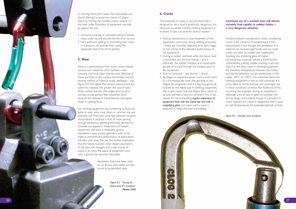
Figure 8.3 Testing thefailure load of a karabiner
Photo: DMM
6. Cracks
The presence of cracks in any structure that isdesigned to carry load is potentially dangerous, butobviously so where metallic climbing equipment isinvolved. Cracks can arise for several reasons:
• During manufacture or heat-treatment of theequipment, commonly during welding processes– these are invariably detected at an early stage,or not critical to the intended performance ofthe equipment.
• During a sudden overload when the failure loadis exceeded and the item breaks – this iseffectively the sudden initiation and catastrophicgrowth of a crack through the weakest part ofthe equipment.
• Due to corrosion – see Section 1 above.• By fatigue as explained above. Such a crack starts
at a microscopically small size, growing as thefatigue life progresses until it is big enough to benoticed by the naked eye. In climbing equipment,this usually means that the fatigue life is nearly atan end, and that a failure is imminent.This is thereason for recommending regular inspections ofequipment both with the naked eye and with amagnifying glass, and when such a crack isdetected to retire the item immediately.
Continued use of a cracked item will almostcertainly lead rapidly to sudden failure –a very dangerous situation.
Another relevant consideration when consideringcracks is the influence of temperature. If thetemperature is low enough, the brittleness of amaterial can increase significantly and any smallcracks are liable to sudden and catastrophicbreaking, like shattering glass. At highertemperatures, materials exhibit a more ductilecharacteristic making sudden cracking much lesslikely. For the alloys used in climbing equipment,the transition temperature between this brittleand ductile behaviour occurs somewhere in therange –50ºC to +50ºC.The important factor forclimbing equipment is that at cold extremes, it ismore liable to brittle fracture, and prolonged usein these conditions increases the likelihood of thisoccurring (for example, during an expedition).Although a lot of care is taken to consider thisduring design and material choice, it is prudent tocheck regularly for cracks in equipment that is usedat cold temperatures for extended periods of time.
37
Figure 8.4 Grooved, worn karabiner
In climbing terms, this means that reasonable useshould attempt to avoid any chance of fatiguefailure by limiting the number and/or severity ofthe load cycles. Examples of equipment use thatgo against this are:
• excessive torquing, or repeated hitting of hiddenrocks under ice, will shorten the life of an ice tool;
• hard, awkward walking or scrambling over rocksin crampons will shorten their useful life(especially that of the front points).
5. Wear
Wear is a phenomenon that occurs when metallicsurfaces are rubbed by other surfaces underpressure, and local shear stresses arise. Because ofthese, particles on the surface are eroded, and thephysical volume of material locally decreases – seeFigure 8.4.The higher the contact pressure and thesofter the material, the greater the rate of wear.Sharp surface features (like edges and corners)will also erode quicker than smoother parts,because the stresses in those features are higherunder a rubbing force.
For climbing equipment, any contacting surfaces areliable to wear since most alloys in common use arerelatively soft.The most usual high-pressure situationencountered in practice is that of ropes passingthrough karabiners, abseiling and belay devices etc.Grooves can appear in these items of metallicequipment, and since a noticeable grooverepresents a new surface geometry with somematerial removed, the performance of these itemswill alter over time.This has the further implicationthat the failure load and other design parametersof the item are changed, and a safe course ofaction is to retire the piece of equipment oncesuch a groove has become noticeable.
Karabiners that have been usedon via ferrata wire cables are alsoprone to accelerated wear.
36
239B - BMC Care & Maint Inside 3/28/07 1:01 PM Page 36
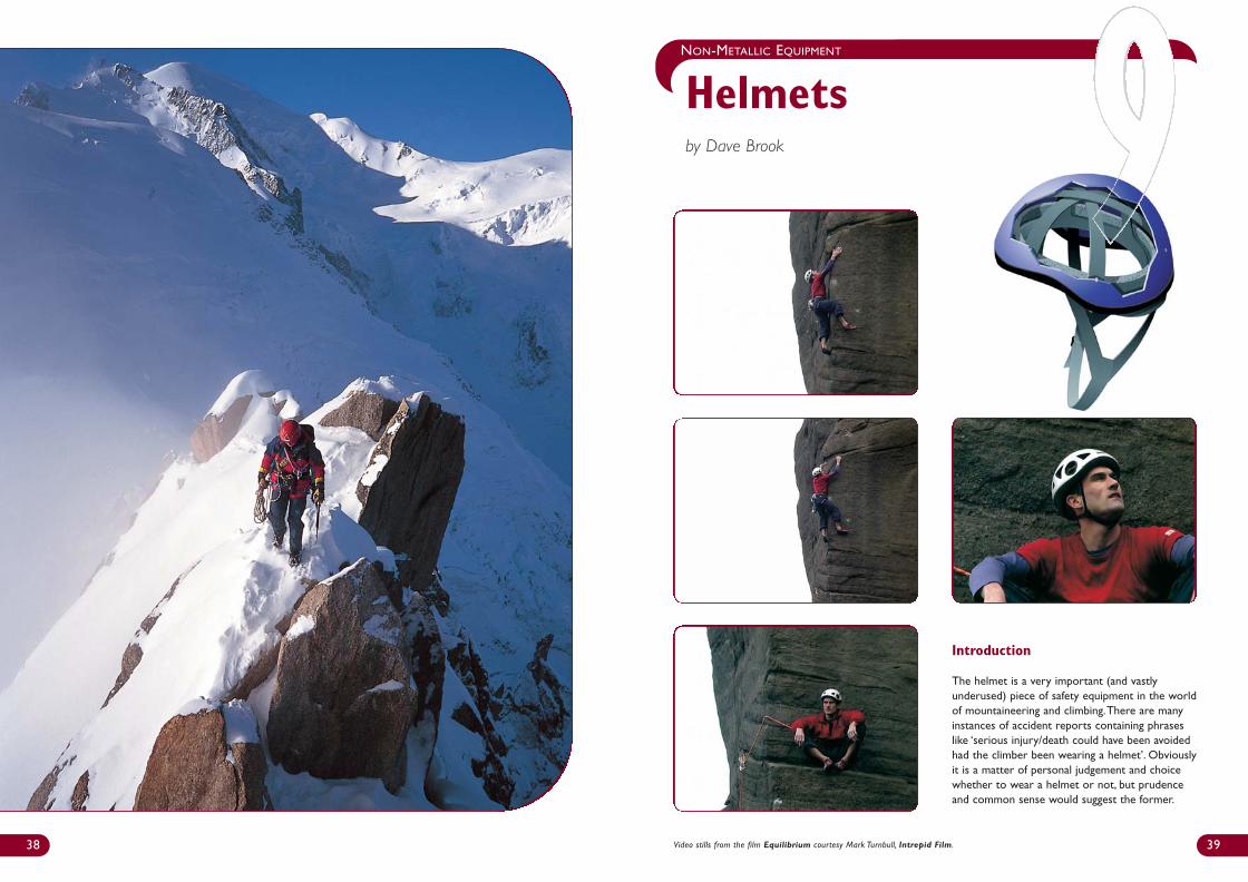
39
NON-METALLIC EQUIPMENT
Helmetsby Dave Brook
38 Video stills from the film Equilibrium courtesy Mark Turnbull, Intrepid Film.
Introduction
The helmet is a very important (and vastlyunderused) piece of safety equipment in the worldof mountaineering and climbing.There are manyinstances of accident reports containing phraseslike ‘serious injury/death could have been avoidedhad the climber been wearing a helmet’. Obviouslyit is a matter of personal judgement and choicewhether to wear a helmet or not, but prudenceand common sense would suggest the former.
239B - BMC Care & Maint Inside 3/28/07 1:01 PM Page 38
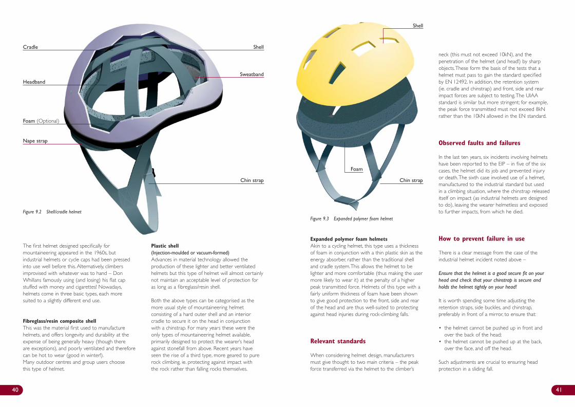
Expanded polymer foam helmetsAkin to a cycling helmet, this type uses a thicknessof foam in conjunction with a thin plastic skin as theenergy absorber, rather than the traditional shelland cradle system.This allows the helmet to belighter and more comfortable (thus making the usermore likely to wear it) at the penalty of a higherpeak transmitted force. Helmets of this type with afairly uniform thickness of foam have been shownto give good protection to the front, side and rearof the head and are thus well-suited to protectingagainst head injuries during rock-climbing falls.
Relevant standards
When considering helmet design, manufacturersmust give thought to two main criteria – the peakforce transferred via the helmet to the climber’s
neck (this must not exceed 10kN), and thepenetration of the helmet (and head!) by sharpobjects.These form the basis of the tests that ahelmet must pass to gain the standard specifiedby EN 12492. In addition, the retention system(ie. cradle and chinstrap) and front, side and rearimpact forces are subject to testing.The UIAAstandard is similar but more stringent; for example,the peak force transmitted must not exceed 8kNrather than the 10kN allowed in the EN standard.
Observed faults and failures
In the last ten years, six incidents involving helmetshave been reported to the EIP – in five of the sixcases, the helmet did its job and prevented injuryor death.The sixth case involved use of a helmet,manufactured to the industrial standard but usedin a climbing situation, where the chinstrap releaseditself on impact (as industrial helmets are designedto do), leaving the wearer helmetless and exposedto further impacts, from which he died.
How to prevent failure in use
There is a clear message from the case of theindustrial helmet incident noted above –
Ensure that the helmet is a good secure fit on yourhead and check that your chinstrap is secure andholds the helmet tightly on your head!
It is worth spending some time adjusting theretention straps, side buckles, and chinstrap,preferably in front of a mirror, to ensure that:
• the helmet cannot be pushed up in front andover the back of the head;
• the helmet cannot be pushed up at the back,over the face, and off the head.
Such adjustments are crucial to ensuring headprotection in a sliding fall.
40 41
Figure 9.2 Shell/cradle helmet
Shell
Sweatband
Chin strap Chin strap
Nape strap
Foam (Optional)
Cradle
Headband
Figure 9.3 Expanded polymer foam helmet
Shell
Foam
The first helmet designed specifically formountaineering appeared in the 1960s, butindustrial helmets or cycle caps had been pressedinto use well before this. Alternatively, climbersimprovised with whatever was to hand – DonWhillans famously using (and losing) his flat capstuffed with money and cigarettes! Nowadays,helmets come in three basic types, each moresuited to a slightly different end use.
Fibreglass/resin composite shellThis was the material first used to manufacturehelmets, and offers longevity and durability at theexpense of being generally heavy (though thereare exceptions), and poorly ventilated and thereforecan be hot to wear (good in winter!).Many outdoor centres and group users choosethis type of helmet.
Plastic shell (Injection-moulded or vacuum-formed)Advances in material technology allowed theproduction of these lighter and better ventilatedhelmets but this type of helmet will almost certainlynot maintain an acceptable level of protection foras long as a fibreglass/resin shell.
Both the above types can be categorised as themore usual style of mountaineering helmetconsisting of a hard outer shell and an interiorcradle to secure it on the head in conjunctionwith a chinstrap. For many years these were theonly types of mountaineering helmet available,primarily designed to protect the wearer’s headagainst stonefall from above. Recent years haveseen the rise of a third type, more geared to purerock climbing, ie. protecting against impact withthe rock rather than falling rocks themselves.
239B - BMC Care & Maint Inside 3/28/07 1:01 PM Page 40
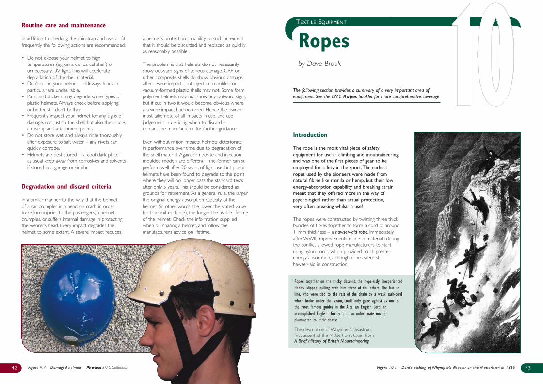
Introduction
The rope is the most vital piece of safetyequipment for use in climbing and mountaineering,and was one of the first pieces of gear to beemployed for safety in the sport.The earliestropes used by the pioneers were made fromnatural fibres like manila or hemp, but their lowenergy-absorption capability and breaking strainmeant that they offered more in the way ofpsychological rather than actual protection,very often breaking whilst in use!
The ropes were constructed by twisting three thickbundles of fibres together to form a cord of around11mm thickness – a hawser-laid rope. Immediatelyafter WWII, improvements made in materials duringthe conflict allowed rope manufacturers to startusing nylon cords, which provided much greaterenergy absorption, although ropes were stillhawser-laid in construction.
“Roped together on the tricky descent, the hopelessly inexperiencedHadow slipped, pulling with him three of the others. The last inline, who were tied to the rest of the chain by a weak sash-cordwhich broke under the strain, could only gape aghast as one ofthe most famous guides in the Alps, an English Lord, anaccomplished English climber and an unfortunate novice,plummeted to their deaths.”
“The description of Whymper’s disastrous first ascent of the Matterhorn, taken from A Brief History of British Mountaineering
The following section provides a summary of a very important area ofequipment. See the BMC Ropes booklet for more comprehensive coverage.
43
TEXTILE EQUIPMENT
Ropesby Dave Brook
Routine care and maintenance
In addition to checking the chinstrap and overall fitfrequently, the following actions are recommended:
• Do not expose your helmet to hightemperatures (eg. on a car parcel shelf) orunnecessary UV light.This will acceleratedegradation of the shell material.
• Don’t sit on your helmet – sideways loads inparticular are undesirable.
• Paint and stickers may degrade some types ofplastic helmets. Always check before applying,or better still don’t bother!
• Frequently inspect your helmet for any signs ofdamage, not just to the shell, but also the cradle,chinstrap and attachment points.
• Do not store wet, and always rinse thoroughlyafter exposure to salt water – any rivets canquickly corrode.
• Helmets are best stored in a cool dark place –as usual keep away from corrosives and solventsif stored in a garage or similar.
Degradation and discard criteria
In a similar manner to the way that the bonnetof a car crumples in a head-on crash in orderto reduce injuries to the passengers, a helmetcrumples, or suffers internal damage in protectingthe wearer’s head. Every impact degrades thehelmet to some extent. A severe impact reduces
a helmet’s protection capability to such an extentthat it should be discarded and replaced as quicklyas reasonably possible.
The problem is that helmets do not necessarilyshow outward signs of serious damage. GRP orother composite shells do show obvious damageafter severe impacts, but injection-moulded orvacuum-formed plastic shells may not. Some foampolymer helmets may not show any outward signs,but if cut in two it would become obvious wherea severe impact had occurred. Hence the ownermust take note of all impacts in use, and usejudgement in deciding when to discard –contact the manufacturer for further guidance.
Even without major impacts, helmets deterioratein performance over time due to degradation ofthe shell material. Again, composite and injectionmoulded models are different – the former can stillperform well after 20 years of light use, but plastichelmets have been found to degrade to the pointwhere they will no longer pass the standard testsafter only 5 years.This should be considered asgrounds for retirement. As a general rule, the largerthe original energy absorption capacity of thehelmet (in other words, the lower the stated valuefor transmitted force), the longer the usable lifetimeof the helmet. Check the information suppliedwhen purchasing a helmet, and follow themanufacturer’s advice on lifetime.
42 Figure 9.4 Damaged helmets Photos: BMC Collection Figure 10.1 Doré’s etching of Whymper’s disaster on the Matterhorn in 1865
239B - BMC Care & Maint Inside 3/28/07 1:02 PM Page 42
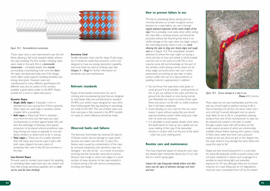
These ropes were a vast improvement over the oldfibres, allowing a fall to be stopped reliably withoutthe rope breaking.The first modern climbing ropeswere made in the early 50s in a kernmantleconstruction – a braided sheath (the mantle)surrounding a load-bearing inner core (the kern).All ropes manufactured today are of this design,which offers vastly superior handling, durability andenergy absorption. However, ropes aremanufactured to many different specifications fordifferent uses, and an outline of the varietiesavailable is given below (refer to the BMC Ropesbooklet for a more in depth discussion):
Dynamic Ropes• Single (full) ropes – Classically 11mm in
diameter, but now varying from 9.2mm upwards,these ropes are used singly in situations wherea leader fall is a possibility.
• Half ropes – Historically 9mm in diameter (now from 8.1mm), two half ropes are usedsimultaneously to protect against leader falls, andhave the advantage of allowing more spacedprotection to be placed without prohibitive ropedrag. Having two ropes as opposed to one alsoallows climbers to abseil twice as far in one go.
• Twin ropes – These are of a smaller diameterthan half ropes, and must be used in pairs withboth ropes clipped into every piece ofprotection.Very rare in the UK, but common inthe Alps.
Low-Stretch RopesPrimarily used by climbers (and cavers) for abseilingor ascending, these ropes have very low stretch andhave little energy absorbing capability and so mustnot be used for lead climbing!
Accessory CordSmaller diameter rope, used for slings, Prusik loops,etc. It should be noted that accessory cord is notdesigned to have any energy absorption capability,and must never be used as climbing rope. SeeChapter 3 – Slings for further information onstandards, care and maintenance.
Relevant standards
Ropes of kernmantle construction for use inclimbing and mountaineering (and that are designedto hold leader falls) are manufactured to standardEN 892. Low stretch ropes designed for uses otherthan holding leader falls (eg. abseiling or ascending)are made to EN 1891.The use of these ropes andtheir sub-types is fully covered in the BMC bookleton ropes, to which reference should be made.
Observed faults and failures
The Technical Committee has received 20 reportsof failures and/or serious damage to ropes (bothdynamic and static) over the last 15 years.Twofailures were caused by contamination of the ropeby corrosive substances, one (dynamic) rope wasdamaged – but did not fail – as a result of excessivejumaring, and the remainder were due to seriousabrasion over rough or sharp rock edges. In a smallnumber of cases, abrasion to the rope resulted inits failure during a fall with serious consequences,including one fatality.
How to prevent failure in use
The key to preventing failure during use is tominimise abrasion, or at least recognise seriousabrasion to a rope before you use it throughregular physical inspection of the entire length of therope.This is probably most easily done whilst coilingthe rope after a climbing session, and should bepractised without fail. Assuming that there is novisible damage to the rope when you begin using it,the overriding priority whilst in use is to avoidallowing the rope to drag over sharp edges and roughrock as in Figure 10.3.This necessitates constantattention to where the rope might run during aclimb, and also to how and where it will be loadedover the rock in the event of a fall.This in turnrequires some skill and knowledge on the part ofthe climbers whilst placing runners (look out forsharp edges and protrusions near your runnerplacements) and setting up top-rope or belayanchors (often the use of a rope protector orpadding material is appropriate). In addition:
• Do not throw the rope down onto gritty orsandy ground if at all possible – small particles ofdirt or grit can adhere to the nylon and then beground into the sheath or core during normaluse. Potentially this could cut some of the ropesfibres and cause it to fail with no visible evidencethat it had been weakened.
• Avoid standing on your rope for the very samereason. It goes without saying that you shouldexercise extreme caution whilst using your ropewith ice tools and crampons.
• It is advisable to avoid speedy abseils, which allowthe abseil device to heat up very rapidly and cancause melting of the rope if the descenderremains in contact with it at the end of the abseil– nylon has a low melting point!
Routine care and maintenance
The most important aspect of caring for your ropehas already been mentioned above, but it is so vitalthat it is worth saying again:
Inspect the rope frequently (ideally before and afterevery use) for signs of abrasion, damage and wearand tear.
Most ropes are not user-maintainable, and the onlytask you should need to perform during its life isthat of cleaning it.To do this use warm water and avery mild (pH neutral) detergent such as naturalsoap flakes (if any at all) or a proprietary cleaningproduct from one of the manufacturers. A rope canbe cleaned and soaked in the bath, or pulledthrough a plastic tube with soft brushes on theinside, several versions of which are commerciallyavailable. Always follow cleaning with copious rinsingin fresh, clean water and never use a pressurewasher as this can drive any grit or dirt deeper intothe rope, where it may damage the nylon fibres andcause the rope to fail.
Ropes are best stored (long term) in a cool dark,dry place. Be especially careful to avoid contact withcorrosive substances in places such as garages. It issensible to avoid strong light and extendedexposure to UV rays, although there are no knowninstances of a rope failing due to UV degradation,since the core is protected from UV by the sheath.
4544
Figure 10.2 Kernmantle/core construction
Figure 10.3 Serious damage to a rope in usePhoto: BMC Collection
239B - BMC Care & Maint Inside 3/28/07 1:02 PM Page 44
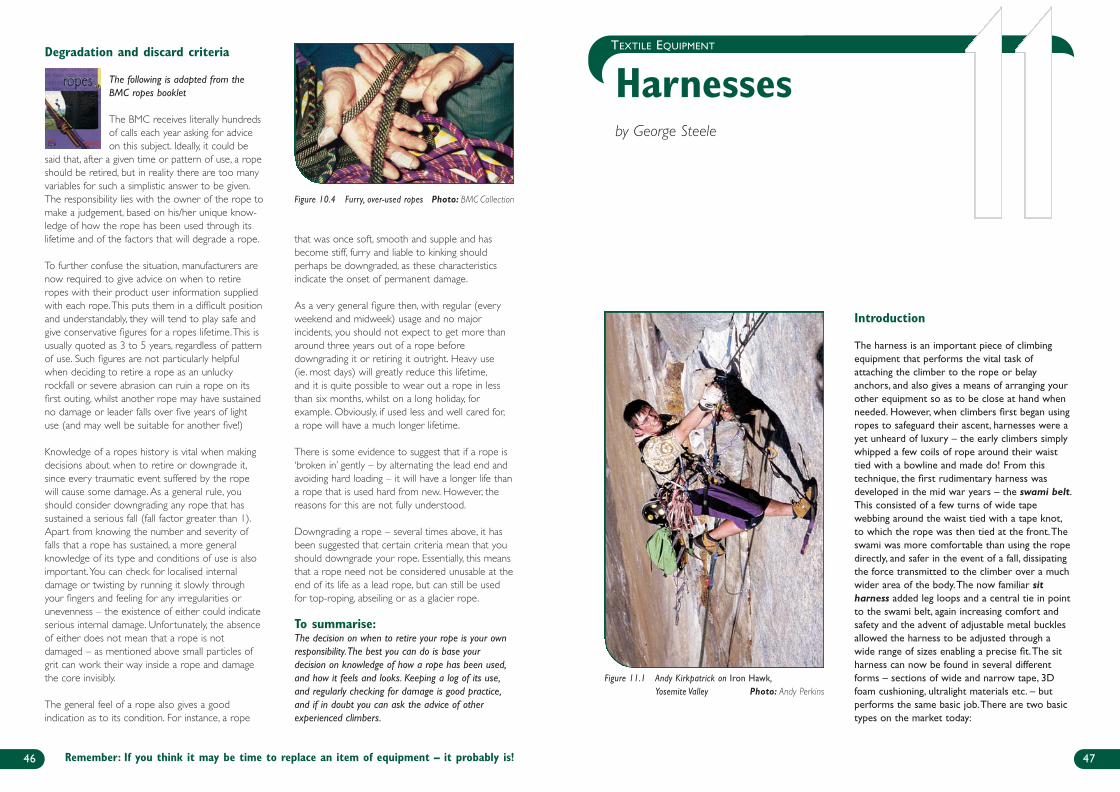
47
TEXTILE EQUIPMENT
Harnesses by George Steele
Introduction
The harness is an important piece of climbingequipment that performs the vital task ofattaching the climber to the rope or belayanchors, and also gives a means of arranging yourother equipment so as to be close at hand whenneeded. However, when climbers first began usingropes to safeguard their ascent, harnesses were ayet unheard of luxury – the early climbers simplywhipped a few coils of rope around their waisttied with a bowline and made do! From thistechnique, the first rudimentary harness wasdeveloped in the mid war years – the swami belt.This consisted of a few turns of wide tapewebbing around the waist tied with a tape knot,to which the rope was then tied at the front.Theswami was more comfortable than using the ropedirectly, and safer in the event of a fall, dissipatingthe force transmitted to the climber over a muchwider area of the body.The now familiar sitharness added leg loops and a central tie in pointto the swami belt, again increasing comfort andsafety and the advent of adjustable metal bucklesallowed the harness to be adjusted through awide range of sizes enabling a precise fit.The sitharness can now be found in several differentforms – sections of wide and narrow tape, 3Dfoam cushioning, ultralight materials etc. – butperforms the same basic job.There are two basictypes on the market today:
Degradation and discard criteria
The following is adapted from theBMC ropes booklet
The BMC receives literally hundredsof calls each year asking for adviceon this subject. Ideally, it could be
said that, after a given time or pattern of use, a ropeshould be retired, but in reality there are too manyvariables for such a simplistic answer to be given.The responsibility lies with the owner of the rope tomake a judgement, based on his/her unique know-ledge of how the rope has been used through itslifetime and of the factors that will degrade a rope.
To further confuse the situation, manufacturers arenow required to give advice on when to retireropes with their product user information suppliedwith each rope.This puts them in a difficult positionand understandably, they will tend to play safe andgive conservative figures for a ropes lifetime.This isusually quoted as 3 to 5 years, regardless of patternof use. Such figures are not particularly helpfulwhen deciding to retire a rope as an unluckyrockfall or severe abrasion can ruin a rope on itsfirst outing, whilst another rope may have sustainedno damage or leader falls over five years of lightuse (and may well be suitable for another five!)
Knowledge of a ropes history is vital when makingdecisions about when to retire or downgrade it,since every traumatic event suffered by the ropewill cause some damage. As a general rule, youshould consider downgrading any rope that hassustained a serious fall (fall factor greater than 1).Apart from knowing the number and severity offalls that a rope has sustained, a more generalknowledge of its type and conditions of use is alsoimportant.You can check for localised internaldamage or twisting by running it slowly throughyour fingers and feeling for any irregularities orunevenness – the existence of either could indicateserious internal damage. Unfortunately, the absenceof either does not mean that a rope is notdamaged – as mentioned above small particles ofgrit can work their way inside a rope and damagethe core invisibly.
The general feel of a rope also gives a goodindication as to its condition. For instance, a rope
that was once soft, smooth and supple and hasbecome stiff, furry and liable to kinking shouldperhaps be downgraded, as these characteristicsindicate the onset of permanent damage.
As a very general figure then, with regular (everyweekend and midweek) usage and no majorincidents, you should not expect to get more thanaround three years out of a rope beforedowngrading it or retiring it outright. Heavy use(ie. most days) will greatly reduce this lifetime,and it is quite possible to wear out a rope in lessthan six months, whilst on a long holiday, forexample. Obviously, if used less and well cared for,a rope will have a much longer lifetime.
There is some evidence to suggest that if a rope is‘broken in’ gently – by alternating the lead end andavoiding hard loading – it will have a longer life thana rope that is used hard from new. However, thereasons for this are not fully understood.
Downgrading a rope – several times above, it hasbeen suggested that certain criteria mean that youshould downgrade your rope. Essentially, this meansthat a rope need not be considered unusable at theend of its life as a lead rope, but can still be usedfor top-roping, abseiling or as a glacier rope.
To summarise:The decision on when to retire your rope is your ownresponsibility.The best you can do is base yourdecision on knowledge of how a rope has been used,and how it feels and looks. Keeping a log of its use,and regularly checking for damage is good practice,and if in doubt you can ask the advice of otherexperienced climbers.
46
Figure 10.4 Furry, over-used ropes Photo: BMC Collection
Remember: If you think it may be time to replace an item of equipment – it probably is!
Figure 11.1 Andy Kirkpatrick on Iron Hawk,Yosemite Valley Photo: Andy Perkins
239B - BMC Care & Maint Inside 3/28/07 1:02 PM Page 46
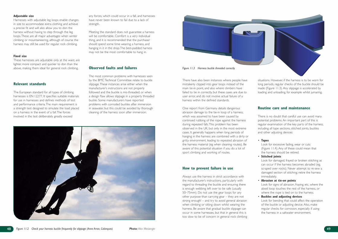
There have also been instances where people havemistakenly clipped into gear loops instead of themain tie-in point, and also where climbers havefailed to tie in correctly, but these cases are due touser error, and do not involve actual failure of aharness within the defined standards.
One report from Germany details dangerousabrasion damage to the tie-in loop of a harness,which was assumed to have been caused bycontinued rubbing of the rope against the harnessduring repeated falls.This problem has beenobserved in the UK, but only in the most extremecases. It generally happens when long periods ofhanging in the harness are combined with a dirty orgritty environment, leading to repeated abrasion ofthe harness material (eg when cleaning routes). Beaware of this potential situation if you do a lot ofsport climbing and working of routes.
How to prevent failure in use
Always use the harness in strict accordance withthe manufacturer’s instructions, particularly withregard to threading the buckle and ensuring thereis enough webbing left over to be safe (usually50–75mm). Do not use the gear loops for anyother purpose than carrying gear – they are notstrong enough! – and try to avoid general abrasionwhen climbing or sitting down whilst wearing theharness. Be aware that gradual buckle slippage canoccur in some harnesses, but that in general this istoo slow to be of concern in general rock climbing
situations. However, if the harness is to be worn forlong periods, regular checks of the buckle should bemade (Figure 11.3). Any slippage is accelerated byloading and unloading, for example whilst jumaring.
Routine care and maintenance
There is no doubt that careful use can avoid manypotential problems. An important part of this isregular examination of the key parts of the harness,including all tape sections, stitched joints, bucklesand other adjusting devices:
• TapesLook for excessive fading, wear or cuts(Figure 11.4). Any of these could mean thatthe harness should be retired.
• Stitched jointsLook for damaged, frayed or broken stitching ascan occur if the harness becomes abraded (eg.scraped over rocks). Never attempt to re-sew adamaged section of stitching; retire the harnessimmediately.
• Abrasion at tie-on pointsLook for signs of abrasion, fraying, etc, where theabseil loop touches the rest of the harness, orwhere the rope is tied on to the harness.
• Buckles and adjusting devicesLook for bending that could affect the operationof the buckle or adjusting device. Also, makeregular checks for corrosion, especially if usingthe harness in a saltwater environment.
49
Adjustable sizeHarnesses with adjustable leg loops enable changesin size to accommodate extra clothing and achievea precise fit and will also allow you to don theharness without having to step through the legloops.These are all major advantages when winterclimbing or mountaineering, although of course theharness may still be used for regular rock climbing.
Fixed sizeThese harnesses are adjustable only at the waist, arelighter, more compact and quicker to don than theabove, making them ideal for general rock climbing.
Relevant standards
The European standard for all types of climbingharnesses is EN 12277. It specifies suitable materialsfor use in harnesses and defines methods of testand performance criteria.The main requirement isa strength test designed to simulate the load placedon a harness in the event of a fall.The forcesinvolved in the test deliberately greatly exceed
any forces, which could occur in a fall, and harnesseshave never been known to fail due to a lack ofstrength.
Meeting the standard does not guarantee a harnesswill be comfortable. Comfort is a very individualthing, and it is recommended that the purchasershould spend some time wearing a harness, andhanging in it in the shop.The best-padded harnessmay not be the most comfortable to hang in.
Observed faults and failures
The most common problems with harnesses seenby the BMC Technical Committee relate to buckleslippage.These instances arise either when themanufacturer’s instructions are not properlyfollowed and the buckle is mis-threaded, or whena design flaw allows slippage in a properly threadedbuckle. Some manufacturers have reportedproblems with corroded buckles after immersionin seawater, but this could be avoided by thoroughcleaning of the harness soon after immersion.
48 Figure 11.2 Check your harness buckle frequently for slippage (Anne Arran, Calanques) Photo: Alex Messenger
Figure 11.3 Harness buckle threaded correctly
239B - BMC Care & Maint Inside 3/28/07 1:02 PM Page 48
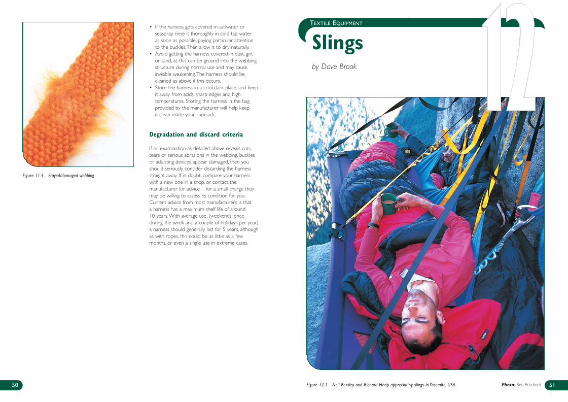
TEXTILE EQUIPMENT
Slingsby Dave Brook
51
• If the harness gets covered in saltwater orseaspray, rinse it thoroughly in cold tap wateras soon as possible, paying particular attentionto the buckles.Then allow it to dry naturally.
• Avoid getting the harness covered in dust, gritor sand, as this can be ground into the webbingstructure during normal use and may causeinvisible weakening.The harness should becleaned as above if this occurs.
• Store the harness in a cool dark place, and keepit away from acids, sharp edges and hightemperatures. Storing the harness in the bagprovided by the manufacturer will help keepit clean inside your rucksack.
Degradation and discard criteria
If an examination as detailed above reveals cuts,tears or serious abrasions in the webbing, bucklesor adjusting devices appear damaged, then youshould seriously consider discarding the harnessstraight away. If in doubt, compare your harnesswith a new one in a shop, or contact themanufacturer for advice – for a small charge theymay be willing to assess its condition for you.Current advice from most manufacturers is thata harness has a maximum shelf life of around10 years.With average use, (weekends, onceduring the week and a couple of holidays per year)a harness should generally last for 5 years, althoughas with ropes, this could be as little as a fewmonths, or even a single use in extreme cases.
50 Figure 12.1 Neil Bentley and Richard Heap appreciating slings in Yosemite, USA Photo: Ben Pritchard
Figure 11.4 Frayed/damaged webbing
239B - BMC Care & Maint Inside 3/28/07 1:02 PM Page 50
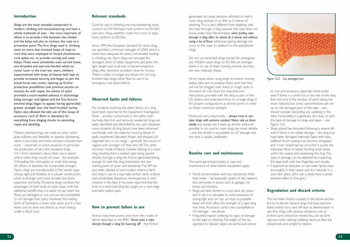
generated can easily become sufficient to melt anylon sling, perhaps in as little as 3 metres oflowering.This is very different from abseiling withthe rope through a sling, because the rope does notmove under load. Nevertheless, when pulling ropethrough a sling after an abseil, do it slowly and withoutusing a lot of force, otherwise glazing damage canoccur to the rope (in addition to the abandonedsling).
Do not use hand-tied slings except for emergencyuse. Modern sewn slings to EN 566 are stronger,there is no risk of them coming undone, and theyare now relatively cheap.
As for ropes, when using slings to extend runningbelays, take care to position them such that theywill not be dragged over sharp or rough rocks inthe event of a fall. Read the manufacturer’sinstructions provided with the sling as part of theCE system, and understand how to arrange slings inthe proper configurations at anchor points in orderto obtain maximum strength.
Finally, and very importantly – always treat in situtape slings with extreme caution! Never rely on themtotally and always use a back-up anchor whereverpossible. In situ cord or rope slings are more reliable– only the sheath is susceptible to UV damage andthe core is usually unaffected.
Routine care and maintenance
The same general principles as care andmaintenance of other textile equipment apply:
• Avoid contamination with any substances otherthan water – be especially careful of oils, cleanersand corrosives in places such as garages, carboots and kitchens.
• Slings are best stored in a cool, dark, dry placeand in use it is advisable to avoid exposure tostrong light and UV rays as much as possible –these will both affect the strength of a tape slingover time. Accessory cord is less susceptible toUV damage – see above.
• Frequently inspect webbing for signs of damageto the tape or stitching.The edges of flat (asopposed to tubular) tapes are particularly prone
to cuts and abrasions, especially whilst underload. If there is a small nick in the side of the slingthen not only is the number of yarns taking thestrain reduced, but stress concentrations are setup on the damaged part of the tape – youshould consider discarding any webbing in thisstate. Fortunately, it is generally very easy to spotthis type of damage to slings and tapes – seeFigure 12.2.
• Slings should be discarded following a severe fall,even if there is no visible damage – the sling mayhave been damaged internally.Tapes that havesuffered shock loading may become elongated,and if over stretching has occurred it causes theindividual fibres to break, forming small lumpswithin the weave and weakening the sling.Thistype of damage can be detected by inspectingthe tape both with the fingertips and visually.
• If exposed to seawater or salt water spray, cleanthoroughly in fresh water, and dry naturally in acool dark place. (Dry salt crystals have a similarabrasive effect to fine grit.)
Degradation and discard criteria
This has been mostly covered in the above section,but to re-iterate: discard slings that have becomefaded and/or furry and stiff due to deterioration inuse. Any slings with obvious abrasions, cuts orbroken yarns should be retired.You can be fairlyrigorous when retiring webbing items, as they areinexpensive and simple to replace.
53
Introduction
Slings are the most versatile component inmodern climbing and mountaineering, and have awhole multitude of uses – the most important ofwhich is to provide a link between the climberand the belay and also to connect the rope to aprotection point.The first slings used in climbingwere no more than knotted loops of rope orcord that were employed to thread chockstones,rock spikes etc. to provide running and staticbelays.These were sometimes even carried loose,and threaded and tied one-handed whilst onroute! Later in the inter-war years, climbersexperimented with loops of hawser-laid rope toprovide increased security, and began to jam theactual knots into cracks, opening up furtherprotection possibilities (see previous section onchocks).As with ropes, the advent of nylonprovided a much-needed advance in technologybeing stronger and lighter, and the first factory-stitched slings began to appear, having appreciablygreater strength over the hand knotted variety.Nylon also allowed the safe use of thin loops ofaccessory cord (3–8mm in diameter) foreverything from slinging chocks to ascendingropes and abseiling.
Modern stitched slings are made of nylon, whichgives softness and flexibility or spectra (dyneema),which is less bulky and more abrasion resistant thannylon – important in some situations. In particular,the production of very thin dyneema slings(12–15mm diameter) allows their use in placeswhere nylon slings would not pass – for example,if threading thin rock spikes or small slots, being20–25mm in diameter for comparable strength.Nylon slings are manufactured of ‘flat’ woven tape(cheap, light and flexible) or a tubular construction,which is stronger and more durable, but moreexpensive and bulky. Dyneema slings combine theadvantages of both kinds of nylon tapes, with theadditional benefit that it is easier to see when thefibres are damaged or cut, and are less susceptibleto UV damage than nylon. However, the meltingpoint of Dyneema is lower than nylon and it is lesselastic and so does not absorb as much energyunder a shock load.
Relevant standards
Cord for use in climbing and mountaineering mustconform to EN 564; tape must conform to EN 565;and sewn slings, whether made from cord or tape,must conform to EN 566.
Since 1994 the European standard for sewn slingshas specified a minimum strength of 22kN, which ismore than adequate for every conceivable loadingin climbing use. Sewn slings are amongst thestrongest items of safety equipment, and given thelight weight and small bulk of dyneema/spectraslings, they represent excellent value for money.There is really no longer any reason for carryingknotted tape slings, other than to use in anemergency and leave behind.
Observed faults and failures
No incidents involving the direct failure of a slinghave been reported to the Equipment InvestigationPanel – another component in the safety chainnormally fails first, and seriously weakened slings areeasily identified and discarded by the user. However,many incidents of sling failure have been observedworldwide, with the majority involving failure ofbadly weathered (abraded, frozen and thawed, UVdegraded etc.) in situ slings – generally this occurs inregions with stronger UV than the UK! The othercommon mode of failure involves melting of a nylonsling resulting from a loaded rope being passeddirectly through a sling, the friction generated beingenough to melt the sling (remember the lowmelting point of nylon and dyneema).The EIP hasalso been advised of one incident where a handtied sling in use as a top-rope anchor came undone,with predictably disastrous consequences. In oneinstance in the Alps, it has been reported that theknot of a hand tied sling has caught on a rock edgeand been pulled open.
How to prevent failure in use
Several important points arise from the modes offailure reported to the BMC. Never pass a ropedirectly through a sling for lowering off – the friction
52
Figure 12.2 Cut, damaged yarn
239B - BMC Care & Maint Inside 3/28/07 1:02 PM Page 52
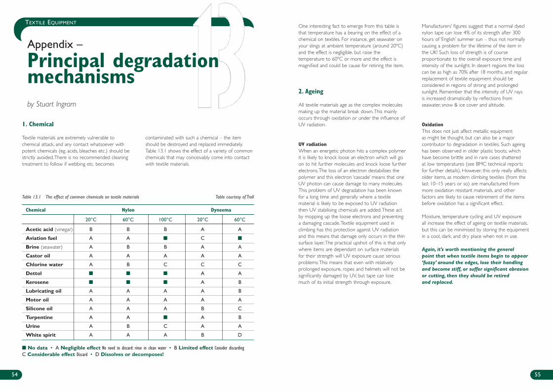
54 55
TEXTILE EQUIPMENTOne interesting fact to emerge from this table isthat temperature has a bearing on the effect of achemical on textiles. For instance, get seawater onyour slings at ambient temperature (around 20ºC)and the effect is negligible, but raise thetemperature to 60ºC or more and the effect ismagnified and could be cause for retiring the item.
2. Ageing
All textile materials age as the complex moleculesmaking up the material break down.This mainlyoccurs through oxidation or under the influence ofUV radiation.
UV radiation When an energetic photon hits a complex polymerit is likely to knock loose an electron which will goon to hit further molecules and knock loose furtherelectrons.The loss of an electron destabilises thepolymer and this electron ‘cascade’ means that oneUV photon can cause damage to many molecules.This problem of UV degradation has been knownfor a long time and generally where a textilematerial is likely to be exposed to UV radiationthen UV stabilising chemicals are added.These actby mopping up the loose electrons and preventinga damaging cascade.Textile equipment used inclimbing has this protection against UV radiationand this means that damage only occurs in the thinsurface layer.The practical upshot of this is that onlywhere items are dependant on surface materialsfor their strength will UV exposure cause seriousproblems.This means that even with relativelyprolonged exposure, ropes and helmets will not besignificantly damaged by UV, but tape can losemuch of its initial strength through exposure.
Manufacturers’ figures suggest that a normal dyednylon tape can lose 4% of its strength after 300hours of ‘English’ summer sun – thus not normallycausing a problem for the lifetime of the item inthe UK! Such loss of strength is of courseproportionate to the overall exposure time andintensity of the sunlight. In desert regions the losscan be as high as 70% after 18 months, and regularreplacement of textile equipment should beconsidered in regions of strong and prolongedsunlight. Remember that the intensity of UV raysis increased dramatically by reflections fromseawater, snow & ice cover and altitude.
OxidationThis does not just affect metallic equipmentas might be thought, but can also be a majorcontributor to degradation in textiles. Such ageinghas been observed in older plastic boots, whichhave become brittle and in rare cases shatteredat low temperatures (see BMC technical reportsfor further details). However, this only really affectsolder items, as modern climbing textiles (from thelast 10–15 years or so) are manufactured frommore oxidation resistant materials, and otherfactors are likely to cause retirement of the itemsbefore oxidation has a significant effect.
Moisture, temperature cycling and UV exposureall increase the effect of ageing on textile materials,but this can be minimised by storing the equipmentin a cool, dark, and dry place when not in use.
Again, it’s worth mentioning the generalpoint that when textile items begin to appear‘fuzzy’ around the edges, lose their handlingand become stiff, or suffer significant abrasionor cutting, then they should be retiredand replaced.
1. Chemical
Textile materials are extremely vulnerable tochemical attack, and any contact whatsoever withpotent chemicals (eg. acids, bleaches etc.) should bestrictly avoided.There is no recommended cleaningtreatment to follow if webbing etc. becomes
contaminated with such a chemical – the itemshould be destroyed and replaced immediately.Table 13.1 shows the effect of a variety of commonchemicals that may conceivably come into contactwith textile materials.
Appendix –
Principal degradationmechanismsby Stuart Ingram
Table 13.1 The effect of common chemicals on textile materials Table courtesy of Troll
Chemical Nylon Dyneema
20°C 60°C 100°C 20°C 60°C
Acetic acid (vinegar) B B B A A
Aviation fuel A A ■ C ■
Brine (seawater) A B B A A
Castor oil A A A A A
Chlorine water A B C C C
Dettol ■ ■ ■ A A
Kerosene ■ ■ ■ A B
Lubricating oil A A A A B
Motor oil A A A A A
Silicone oil A A A B C
Turpentine A A ■ A B
Urine A B C A A
White spirit A A A B D
■ No data • A Negligible effect No need to discard: rinse in clean water • B Limited effect Consider discardingC Considerable effect Discard • D Dissolves or decomposes!
239B - BMC Care & Maint Inside 3/28/07 1:02 PM Page 54
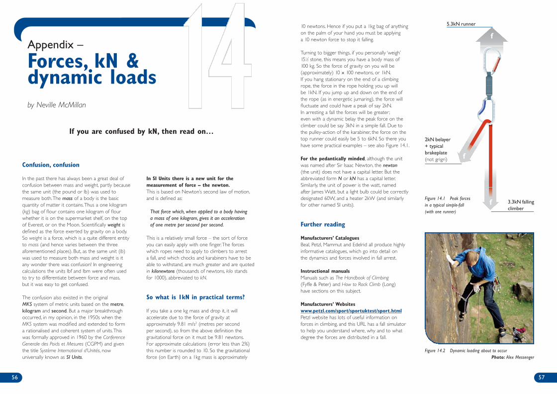
10 newtons. Hence if you put a 1kg bag of anythingon the palm of your hand you must be applyinga 10 newton force to stop it falling.
Turning to bigger things, if you personally ‘weigh’151⁄2 stone, this means you have a body mass of100 kg. So the force of gravity on you will be(approximately) 10 × 100 newtons, or 1kN.If you hang stationary on the end of a climbingrope, the force in the rope holding you up willbe 1kN. If you jump up and down on the end ofthe rope (as in energetic jumaring), the force willfluctuate and could have a peak of say 2kN.In arresting a fall the forces will be greater ;even with a dynamic belay the peak force on theclimber could be say 3kN in a simple fall. Due tothe pulley-action of the karabiner, the force on thetop runner could easily be 5 to 6kN. So there youhave some practical examples – see also Figure 14.1.
For the pedantically minded, although the unitwas named after Sir Isaac Newton, the newton(the unit) does not have a capital letter. But theabbreviated form N or kN has a capital letter.Similarly, the unit of power is the watt, namedafter James Watt, but a light bulb could be correctlydesignated 60W, and a heater 2kW (and similarlyfor other named SI units).
Further reading
Manufacturers’ CataloguesBeal, Petzl, Mammut and Edelrid all produce highlyinformative catalogues, which go into detail onthe dynamics and forces involved in fall arrest.
Instructional manualsManuals such as The Handbook of Climbing(Fyffe & Peter) and How to Rock Climb (Long)have sections on this subject.
Manufacturers’ Websiteswww.petzl.com/sport/sportuktest/sport.htmlPetzl website has lots of useful information onforces in climbing, and this URL has a fall simulatorto help you understand where, why and to whatdegree the forces are distributed in a fall.
57
Confusion, confusion
In the past there has always been a great deal ofconfusion between mass and weight, partly becausethe same unit (the pound or lb) was used tomeasure both.The mass of a body is the basicquantity of matter it contains.Thus a one kilogram(kg) bag of flour contains one kilogram of flourwhether it is on the supermarket shelf, on the topof Everest, or on the Moon. Scientifically weight isdefined as the force exerted by gravity on a body.So weight is a force, which is a quite different entityto mass (and hence varies between the threeaforementioned places). But, as the same unit (lb)was used to measure both mass and weight is itany wonder there was confusion! In engineeringcalculations the units lbf and lbm were often usedto try to differentiate between force and mass,but it was easy to get confused.
The confusion also existed in the originalMKS system of metric units based on the metre,kilogram and second. But a major breakthroughoccurred, in my opinion, in the 1950s when theMKS system was modified and extended to forma rationalised and coherent system of units.Thiswas formally approved in 1960 by the ConferenceGenerale des Poids et Mesures (CGPM) and giventhe title Système International d’Unités, nowuniversally known as SI Units.
In SI Units there is a new unit for themeasurement of force – the newton.This is based on Newton’s second law of motion,and is defined as:
That force which, when applied to a body havinga mass of one kilogram, gives it an accelerationof one metre per second per second.
This is a relatively small force – the sort of forceyou can easily apply with one finger.The forceswhich ropes need to apply to climbers to arresta fall, and which chocks and karabiners have to beable to withstand, are much greater and are quotedin kilonewtons (thousands of newtons, kilo standsfor 1000), abbreviated to kN.
So what is 1kN in practical terms?
If you take a one kg mass and drop it, it willaccelerate due to the force of gravity atapproximately 9.81 m/s2 (metres per secondper second), so from the above definition thegravitational force on it must be 9.81 newtons.For approximate calculations (error less than 2%)this number is rounded to 10. So the gravitationalforce (on Earth) on a 1kg mass is approximately
56
Appendix –
Forces, kN &dynamic loadsby Neville McMillan
If you are confused by kN, then read on…
Figure 14.2 Dynamic loading about to occur Photo: Alex Messenger
f
f
f
9kN
6kN
15kN5.3kN runner
2kN belayer+ typicalbrakeplate(not grigri)
3.3kN fallingclimber
Figure 14.1 Peak forces in a typical simple-fall (with one runner)
239B - BMC Care & Maint Inside 3/28/07 1:02 PM Page 56
59
General BMC Summit No 15 – Technical Committee,
PPE and CEN:What are they?BMC Summit No 17 – Technical Conference 1999:
Ropes, boots and crampons.BMC Summit No 18 – Retiring GearOTE No 108 (June 2001) – Latest gear updateOTE No 109 (July 2001) – More latest gear
Helmets BMC Summit 19 – Helmet testing programme Part 1BMC Summit 20 – Helmet testing programme Part 2OTE No 102 (Nov 2000) – Helmet reviewClimber (July 2000) – Helmet reviewRock & Ice No 94 (August 1999) – Helmet reviewClimber (July 2001) – Helmet testing and reviews
Ropes Climber (August 2000) – Rope reviewRock & Ice No 99 (April 2000) – Rope review
Camming devices Climber (March 2000) – Cams reviewClimbing (US) No 193 – Cams reviewRock & Ice (July 2001) – Latest camming devices
Crampons Climber (January 2000) – Review
Harnesses Climbing (US) No 199 – Reviews and criteriaClimber (May 2001) – All-round Harnesses
Chocks & nuts Climbing (US) No 193 – Reviews
(Some models reviewed unavailable in the UK)
Belaying & ascending devices Rock & Ice No 98 (February 2000) – Reviews
(Some models reviewed unavailable in the UK)
In addition to the above, On the Edge, Climbing (US)and Rock+Ice all publish annual gear reviews,detailing the latest technology in each area.Climbing (US) has a ‘technical tips’ section in eachissue illustrating the proper (and sometimes quiteinnovative) ways to use certain pieces ofequipment.The BMC website (www.thebmc.co.uk)and Summit magazine feature regular technicalarticles and updates.
1. Useful Articles
There are many useful articles published each year on the technical aspects of mountaineering and climbinggear.They also offer good advice on what to consider when buying these items, and how to choose the modelsmost suited to you. For clarity and up to date information, only articles from the last couple of years areincluded.
58
Further Reading and References
2. Useful books and publications
There are many textbooks available covering in-depth the techniques required to make safe useof climbing and mountaineering equipment.Much of what they say is relevant to care andmaintenance of your equipment, mainly underthe ‘how to prevent failure during use’ banner.Some of the better sources are:
The Handbook of Climbing (Fyffe & Peter)
Climbing Anchors: How to rock climb (Long)
Complete guide to rope techniques (Shepherd)
How to rock climb (Long)
Ice world (Lowe)
Mountaincraft & Leadership (Langmuir)
Extreme Alpinism (Twight)
Ice tools & techniques (Climbing magazine)
3. Other resources
BMC website – www.thebmc.co.ukA full list of the reports held at the BMC oninvestigations into equipment failures can beobtained from the technical section of the website,or from the BMC office.You will also find regularupdates on current research and importantinvestigations here.
UIAA journal – available from www.uiaa.chor +41 31.370.18.28Regular technical articles are run in the journal ofthe world body for mountaineering. Copies aremailed direct to affiliated federations, and thesearticles will be reproduced in Summit magazine ifrelevant.
Manufacturers’ Catalogues and WebsitesThese often go into a good amount of detailregarding the construction and testing ofequipment. Particularly useful are catalogues fromBeal, Petzl and DMM. Black Diamond occasionallyproduce information leaflets about new productsand their own testing programmes.
239B - BMC Care & Maint Inside 3/28/07 1:13 PM Page 58

Care and Maintenanceequipment standards – equipment wear and failure – routine checks and care
239B BMC C&M Cover Collect 1/11/07 4:17 PM Page 1