Embed Size (px)
Citation preview

pCO2 - controllore elettronico programmabilepCO2electronic programmable controller
Manuale d’installazione
User manual
LEGGI E CONSERVAQUESTE ISTRUZIONI
READ AND SAVE THESE INSTRUCTIONS

Vogliamo farvi risparmiare tempo e denaro!Vi assicuriamo che la completa letturadi questo manuale vi garantirà una corretta installazione ed un sicuro utilizzo del prodotto descritto.
AVVERTENZE IMPORTANTI
PRIMA DI INSTALLARE O INTERVENIRE SULL’APPARECCHIO, LEGGERE ATTENTAMENTEE SEGUIRE LE ISTRUZIONI CONTENUTE IN QUESTO MANUALE.
Questa apparecchiatura è stata costruita per funzionare senza rischi per gli scopi prefissati purché:• l’installazione, la conduzione e la manutenzione
siano eseguite secondo le istruzioni contenute in questo manuale;
• le condizioni dell’ambiente e della tensione di alimentazione rientrino tra quelle specificate.
Ogni utilizzo diverso da questo e l’apporto dimodifiche, non espressamente autorizzate dalcostruttore, sono da intendersi impropri.La responsabilità di lesioni o danni causati dauso improprio ricadrà esclusivamente sull’utilizzatore.Si osservi che questa macchina contiene componenti elettrici sotto tensione e quindi tuttele operazioni di servizio o manutenzione devonoessere condotte da personale esperto e qualificato,cosciente delle necessarie precauzioni.Prima di accedere alle parti interne sezionare lamacchina dalla rete elettrica.Smaltimento delle parti del controlloreIl controllore è composto da parti in metallo, daparti in plastica e da una batteria al Litio.Tuttequeste parti vanno smaltite secondo le Normativelocali in materia di smaltimento.
We wish to save you time andmoney!We can assure you that a thorough reading of this manual will guarantee correct installation and safe use of theproduct described.
IMPORTANT
BEFORE INSTALLING OR OPERATING ON THEDEVICE, READ CAREFULLY THE INSTRUCTIONSON THIS MANUAL.
This instrument has been designed to operatewithout risks only if:• Installation, operation and maintenance are
performed according to the instructions of this manual;
• Environmental conditions and supply voltage fall within the values indicated here below;
Any different use or changes which have notbeen authorised by the manufacturer previously,are considered improper.Responsibility for injures or damage caused byimproper use will fall exclusively on the user.Be careful: voltage is present in some electricalcomponents of this instrument, thus all the service or maintenance operations must be doneby expert and skilled personnel only, aware of thenecessary precautions to be taken.Before accessing the internal parts, cut off thepower supply.Disposal of the instrument:The controller is made up of metal and plasticparts and a Lithium batter.
3 pCO2 - cod. +030221835 rel. 3.1 - 11.02.2004
LEGGI E CONSERVAQUESTE ISTRUZIONI
READ AND SAVE THESE INSTRUCTIONS

Indice:
Introduzione 7
1. Caratteristiche generali 71.1 pCO2: SMALL, MEDIUM, LARGE 71.2 Programmabilità 8
2. Architettura hardware 92.1 Codici degli strumenti ed accessori 112.2 Significato degli ingressi/uscite 13
3. Il terminale utente 173.1 Regolazione del contrasto dei display a LCD 173.2 Display LCD 4x20 montaggio a parete o pannello 173.3 Display LED montaggio a parete o pannello 173.4 Display LCD grafico montaggio a parete o pannello 173.5 Display LCD 4x20 montaggio a pannello 183.6 Display LCD grafico montaggio a pannello 183.7 Display a 3 cifre LED 32x72 183.8 Display built-in 193.9 Tastiera terminali pCO 193.10 Funzionalità e caratteristiche del terminale con
display grafico 21
4. Installazione 234.1 Ancoraggio del pCO2 234.2 Alimentazione 234.3 Avvertenze per l’installazione - ambienti di destinazione
e collegamento 244.4 Collegamento degli ingressi analogici 244.5 Collegamento degli ingressi digitali 284.6 Collegamento delle uscite analogiche 314.7 Collegamento delle uscite digitali 314.8 Installazione del terminale utente 334.9 Installazione dell’EPROM di programma del terminale con
display grafico 34
5. Rete pLAN 355.1 Indirizzamento pCO2 365.2 Indirizzamento terminali 365.3 Terminali privati e condivisi 375.4 Connessioni elettriche pLAN 385.5 Remotazione terminale con rete pLAN 395.6 Caratteristiche tecniche rete pLAN 41
6. Schede opzionali 426.1 Chiave di programmazione 426.2 Espansione di memoria 426.3 Scheda seriale per supervisione e teleassistenza RS485 436.4 Scheda seriale RS232 per gestione modem 436.5 Stampante seriale per display LCD 4x20 o 6 LED 436.6 Scheda per stampante seriale per terminale grafico
PCOSERPRN0 436.7 Scheda per gestione umidificatore OEM 44
7. LED di segnalazione e aggiornamento software 457.1 Decodifica dei LED di segnalazione sulla scheda pCO2 457.2 Avvio di un programma alternativo di debug presente
nella key 467.3 Aggiornamento software con Winload32 47
8. Schema generale dei collegamenti elettrici 48
9. Caratteristiche tecniche 509.1 Caratteristiche generali pCO2 509.2 Caratteristiche elettriche pCO2 509.3 Contenitore plastico pCO2 539.4 Caratteristiche tecniche del terminale utente PCOI* e
PCOT* 54
Index:
Introduction 7
1. General features 71.1 pCO2: SMALL, MEDIUM, LARGE 71.2 Programmability 8
2. Hardware structure 92.1 Instrument and accessory codes 112.2 Meaning of the inputs/outputs 15
3. Terminal user 173.1 Contrast control in LCD Display 173.2 Display LCD 4x20 for wall or panel mounting 173.3 LED Display for wall or panel mounting 173.4 LCD Graphic Display for wall or panel mounting 173.5 4x20 LCD Display for panel mounting 183.6 LCD Graphic Display for panel mounting 183.7 3-Digit Display - LED 32x72 183.8 Built-in display 193.9 pCO terminal keypad 193.10 Functions and features of the terminal with graphic
display 21
4. Installation 234.1 Anchoring the pCO2 234.2 Power supply 234.3 Installation warnings - destination and connection
environments 244.4 Connecting the analogue inputs 244.5 Connecting the digital inputs 284.6 Connecting the analogue outputs 314.7 Connecting the digital outputs 314.8 Installing the user terminal 334.9 Installing the program EPROM in the terminal
with graphic display 34
5. pLAN network 355.1 Addressing the pCO2 365.2 Addressing the terminals 365.3 Private / shared terminals 375.4 pLAN electrical connections 385.5 Remote installation of the terminal in a pLAN network 395.6 pLAN network technical specifications 41
6. Optional boards 426.1 Programming key 426.2 Memory expansion 426.3 RS485 serial board for supervisor and telemaintenance 436.4 RS232 : modem interface card 436.5 Serial printer for LCD 4x20 or 6 LED display 436.6 PCOSERPRN0, serial printer card for graphic terminal 436.7 Board for OEM humidifier management 44
7. Signal and software update LED 457.1 Reading the 3 LED’s on the pCO2 board 457.2 Starting an alternative debug program present in the key 467.3 Updating the software with Winload32 47
8. General diagram of the electrical connections 48
9. Technical specifications 509.1 pCO2 general characteristics 509.2 pCO2 electrical specifications 519.3 pCO2 plastic case 539.4 Technical specifications of the PCOI* and PCOT* user
terminals 54
5 pCO2 - cod. +030221835 rel. 3.1 - 11.02.2004

10. Montaggio terminale utente 5610.1 Montaggio a pannello 5610.2 Montaggio a parete 56
11. Dimensioni 5711.1 pCO2 5711.2 Terminale utente 58
12. Ricerca ed eliminazione dei guasti 59
13. pCO2XL - pCO2 ExtraLarge: Controllore elettronico 6213.1 Caratteristiche tecniche 6313.2 Dimensioni 65
Errata corrige e aggiunte in questa versione del manuale 66
10. User terminal mounting 5610.1 Panel mounting 5610.2 Wall mounting 56
11. Dimensions 5711.1 pCO2 5711.2 Terminal user 58
12. Troubleshooting 59
13. pCO2XL - pCO2 ExtraLarge: Electronic controller 6213.1 Technical specifications 6313.2 Dimensions 65
Errata corrige and additions to this manual version 66
INTRODUZIONEpCO2 rappresenta l’evoluzione del noto controllore elettronico pCO, sviluppato da CAREL e destinato a molteplici applicazioni nel campodel condizionamento dell’aria e della refrigerazione. La nuova gamma èstata concepita per soddisfare le necessità e le esigenze dei più importanti costruttori del settore, che richiedono prodotti sempre piùinnovativi e flessibili. Prevede tre taglie differenziate a seconda delleesigenze di I/O e di potenzialità: pCO2 SMALL, pCO2 MEDIUM,pCO2 LARGE.pCO2 assicura la più assoluta versatilità di applicazione, consentendodi realizzare prodotti specifici su richiesta del cliente.I terminali dell’attuale gamma pCO sono tutti compatibili con la nuovaserie di schede. Nella versione LARGE è possibile collegare espansioniI/O con microprocessore, senza dover ricorrere alla rete pLAN.
1. CARATTERISTICHE GENERALI Tutte le versioni di questi controllori utilizzano un microprocessore a 16bit e fino a 6 MByte di memoria FLASH per garantire elevate prestazioni in termini di velocità e disponibilità di memoria. Il controllorepCO2 prevede tre taglie differenziate in funzione del numero d’ingressied uscite per offrire sempre il miglior rapporto prezzo/prestazioni.
1.1 pCO2: SMALL, MEDIUM, LARGE
1.1.1 Caratteristiche comuni a tutte le versioni• Microprocessore a 16 bit, 14 MHz, registri interni ed operazioni a
32 bit, 512 Byte di RAM interna;• 2 MByte o 4 MByte di FLASH MEMORY per programma (espandibile
esternamente fino a un totale di 6 MByte);• 256 kByte RAM statica, preventivamente a richiesta espandibile ad
1 MByte;• 1 seriale RS485 per pLAN;• è predisposto per il collegamento in rete di supervisione RS485;• orologio con batteria al litio sostituibile;• 56 Byte di RAM tamponata con batteria;• selezione indirizzo e LED per pLAN;• contenitore plastico DIN per installazione su guida omega;• alimentazione a 24 Vac/Vdc;• connettore telefonico per terminali pCO;• connettore telefonico per sinottico;• LED presenza alimentazione.
1.1.2 Caratteristiche delle singole versioni
pCO2 SMALL (13 moduli DIN)• 8 ingressi digitali optoisolati a 24 Vac 50/60 Hz o 24 Vdc;• 8 uscite digitali a relè (di cui una con contatto in scambio);• 2 ingressi analogici configurabili tra NTC, PT1000 , ON/OFF;• 3 ingressi analogici configurabili tra NTC, 0/1V, 0/10V, 0/20 mA, 4/20mA;• 4 uscite analogiche 0…10 V.
pCO2 MEDIUM (18 moduli DIN)• 12 ingressi digitali optoisolati a 24 Vac 50/60 Hz o 24 Vdc;• 2 ingressi digitali optoisolati a 24 Vac/Vdc o 230 Vac (50/60 Hz);• 13 uscite digitali a relè (di cui tre con contatti in scambio);• 2 ingressi analogici configurabili tra NTC, PT1000, ON/OFF;• 6 ingressi analogici configurabili tra NTC, 0…1 V, 0…10 V, 0…20 mA,
4…20 mA;• 4 uscite analogiche 0…10 V.
INTRODUCTIONThe pCO2 represents the evolution of the well-known pCO electroniccontrol, developed by CAREL and designed for multiple applications inthe fields of air-conditioning and refrigeration. The new range has beendesigned to satisfy the needs of the leading manufacturers in the sec-tor, who require increasingly innovative and flexible products. There arethree sizes, differentiated according to the I/O and power requirements:pCO2 SMALL, pCO2 MEDIUM, pCO2 LARGE.The pCO2 ensures absolute application versatility, allowing the development of specific products upon customer request.All of the terminals in the current pCO range are compatible with thenew series of boards. In the LARGE version, microprocessor-based I/Oexpansions can be connected without requiring a pLAN network.
1. GENERAL FEATURES All the versions of these controls feature a 16-bit microprocessor andup to 6 MByte of FLASH memory, guaranteeing high performance interms of speed and available memory. The pCO2 control comes in threesizes, differentiated according to the number of inputs and outputs,thus ensuring the best possible price/performance ratio.
1.1 pCO2: SMALL, MEDIUM, LARGE
1.1.1 Features common to all the versions• 16-bit microprocessor, 14 MHz, internal registers and 32 bit
operation, 512 Byte internal RAM;• 2 MByte or 4 MByte FLASH MEMORY for the programs (expandable
externally up to 6 MByte);• 256 kByte static RAM, upon prior request expandable to 1 MByte;• 1 RS485 serial port for pLAN;• ready for connection to RS485 supervisory network;• clock with replaceable lithium battery;• 56 Byte of battery backed-up RAM;• selection of address and LEDs for pLAN;• DIN plastic case for installation on omega rail;• 24Vac/Vdc power supply;• telephone connector for pCO terminals;• telephone connector for synoptic;• LED power signal.
1.1.2 Features of the individual versions
pCO2 SMALL (13 DIN modules)• 8 optically-isolated digital inputs, 24Vac 50/60Hz or 24Vdc;• 8 relay digital outputs (1 of which with changeover contact);• 2 analogue inputs, selectable between NTC, PT1000, ON/OFF;• 3 analogue inputs, selectable between NTC, 0/1V, 0/10V, 0/20 mA,
4/20mA;• 4 analogue outputs, 0/10 V.
pCO2 MEDIUM (18 DIN modules)• 12 optically-isolated digital inputs, 24Vac 50/60Hz or 24Vdc;• 2 optically-isolated digital inputs, 24Vac/Vdc or 230Vac (50/60Hz);• 13 relay digital outputs (3 of which with changeover contacts);• 2 analogue inputs, selectable between NTC, PT1000, ON/OFF;• 6 analogue inputs, selectable between NTC, 0 to 1 V, 0 to 10 V,
0 to 20 mA, 4 to 20 mA;• 4 analogue outputs, 0 to 10 V.
7 pCO2 - cod. +030221835 rel. 3.1 - 11.02.2004
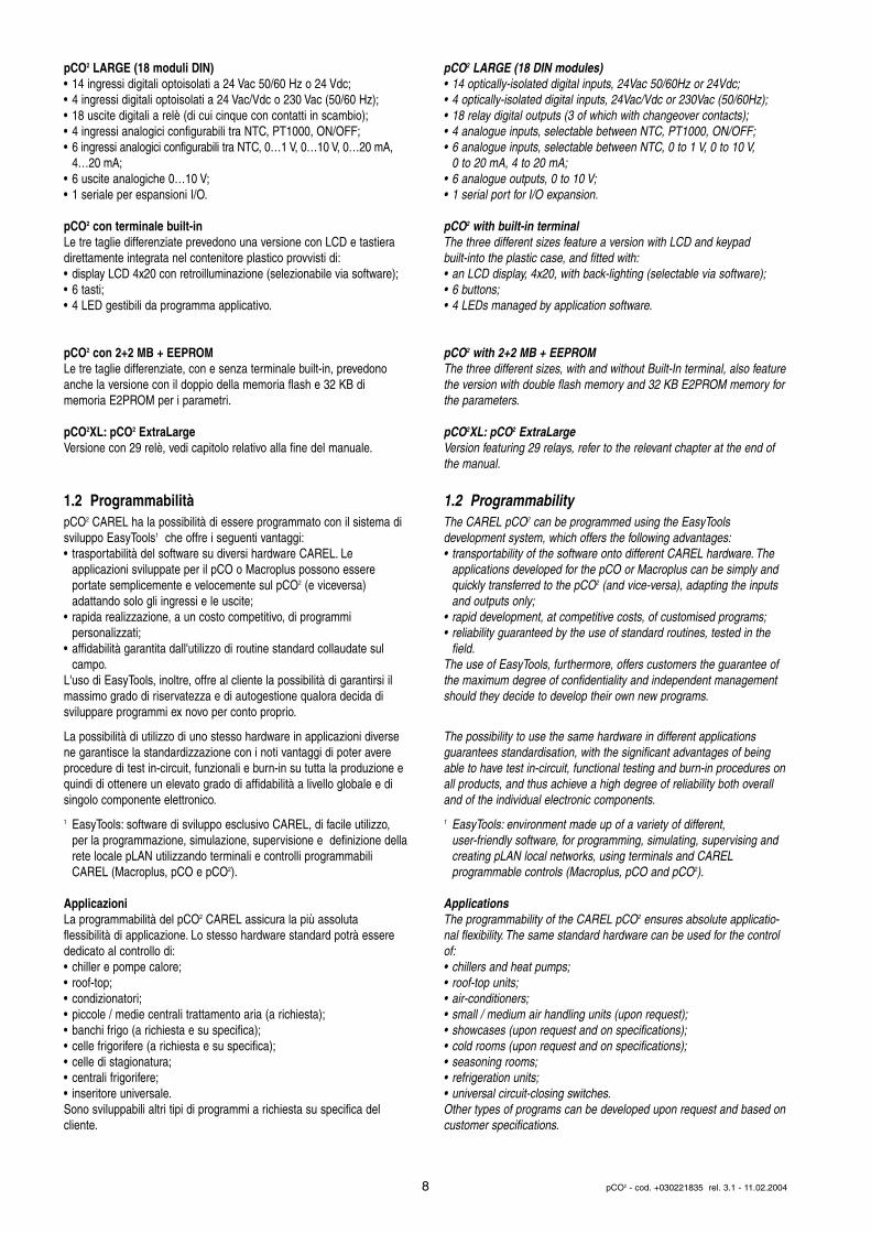
pCO2 LARGE (18 moduli DIN)• 14 ingressi digitali optoisolati a 24 Vac 50/60 Hz o 24 Vdc;• 4 ingressi digitali optoisolati a 24 Vac/Vdc o 230 Vac (50/60 Hz);• 18 uscite digitali a relè (di cui cinque con contatti in scambio);• 4 ingressi analogici configurabili tra NTC, PT1000, ON/OFF;• 6 ingressi analogici configurabili tra NTC, 0…1 V, 0…10 V, 0…20 mA,
4…20 mA;• 6 uscite analogiche 0…10 V;• 1 seriale per espansioni I/O.
pCO2 con terminale built-inLe tre taglie differenziate prevedono una versione con LCD e tastieradirettamente integrata nel contenitore plastico provvisti di:• display LCD 4x20 con retroilluminazione (selezionabile via software);• 6 tasti;• 4 LED gestibili da programma applicativo.
pCO2 con 2+2 MB + EEPROMLe tre taglie differenziate, con e senza terminale built-in, prevedonoanche la versione con il doppio della memoria flash e 32 KB di memoria E2PROM per i parametri.
pCO2XL: pCO2 ExtraLargeVersione con 29 relè, vedi capitolo relativo alla fine del manuale.
1.2 ProgrammabilitàpCO2 CAREL ha la possibilità di essere programmato con il sistema disviluppo EasyTools1 che offre i seguenti vantaggi:• trasportabilità del software su diversi hardware CAREL. Le
applicazioni sviluppate per il pCO o Macroplus possono essere portate semplicemente e velocemente sul pCO2 (e viceversa) adattando solo gli ingressi e le uscite;
• rapida realizzazione, a un costo competitivo, di programmi personalizzati;
• affidabilità garantita dall'utilizzo di routine standard collaudate sul campo.
L'uso di EasyTools, inoltre, offre al cliente la possibilità di garantirsi ilmassimo grado di riservatezza e di autogestione qualora decida di sviluppare programmi ex novo per conto proprio.
La possibilità di utilizzo di uno stesso hardware in applicazioni diversene garantisce la standardizzazione con i noti vantaggi di poter avereprocedure di test in-circuit, funzionali e burn-in su tutta la produzione equindi di ottenere un elevato grado di affidabilità a livello globale e disingolo componente elettronico.
1 EasyTools: software di sviluppo esclusivo CAREL, di facile utilizzo, per la programmazione, simulazione, supervisione e definizione dellarete locale pLAN utilizzando terminali e controlli programmabili CAREL (Macroplus, pCO e pCO2).
ApplicazioniLa programmabilità del pCO2 CAREL assicura la più assoluta flessibilità di applicazione. Lo stesso hardware standard potrà esserededicato al controllo di:• chiller e pompe calore;• roof-top;• condizionatori;• piccole / medie centrali trattamento aria (a richiesta);• banchi frigo (a richiesta e su specifica);• celle frigorifere (a richiesta e su specifica);• celle di stagionatura;• centrali frigorifere;• inseritore universale.Sono sviluppabili altri tipi di programmi a richiesta su specifica delcliente.
pCO2 LARGE (18 DIN modules)• 14 optically-isolated digital inputs, 24Vac 50/60Hz or 24Vdc;• 4 optically-isolated digital inputs, 24Vac/Vdc or 230Vac (50/60Hz);• 18 relay digital outputs (3 of which with changeover contacts);• 4 analogue inputs, selectable between NTC, PT1000, ON/OFF;• 6 analogue inputs, selectable between NTC, 0 to 1 V, 0 to 10 V,
0 to 20 mA, 4 to 20 mA;• 6 analogue outputs, 0 to 10 V;• 1 serial port for I/O expansion.
pCO2 with built-in terminalThe three different sizes feature a version with LCD and keypad built-into the plastic case, and fitted with:• an LCD display, 4x20, with back-lighting (selectable via software);• 6 buttons;• 4 LEDs managed by application software.
pCO2 with 2+2 MB + EEPROMThe three different sizes, with and without Built-In terminal, also featurethe version with double flash memory and 32 KB E2PROM memory forthe parameters.
pCO2XL: pCO2 ExtraLargeVersion featuring 29 relays, refer to the relevant chapter at the end ofthe manual.
1.2 ProgrammabilityThe CAREL pCO2 can be programmed using the EasyTools development system, which offers the following advantages:• transportability of the software onto different CAREL hardware. The
applications developed for the pCO or Macroplus can be simply and quickly transferred to the pCO2 (and vice-versa), adapting the inputs and outputs only;
• rapid development, at competitive costs, of customised programs;• reliability guaranteed by the use of standard routines, tested in the
field.The use of EasyTools, furthermore, offers customers the guarantee ofthe maximum degree of confidentiality and independent managementshould they decide to develop their own new programs.
The possibility to use the same hardware in different applications guarantees standardisation, with the significant advantages of beingable to have test in-circuit, functional testing and burn-in procedures onall products, and thus achieve a high degree of reliability both overalland of the individual electronic components.
1 EasyTools: environment made up of a variety of different, user-friendly software, for programming, simulating, supervising and creating pLAN local networks, using terminals and CAREL programmable controls (Macroplus, pCO and pCO2).
ApplicationsThe programmability of the CAREL pCO2 ensures absolute applicatio-nal flexibility. The same standard hardware can be used for the controlof:• chillers and heat pumps;• roof-top units;• air-conditioners;• small / medium air handling units (upon request);• showcases (upon request and on specifications);• cold rooms (upon request and on specifications);• seasoning rooms;• refrigeration units;• universal circuit-closing switches.Other types of programs can be developed upon request and based oncustomer specifications.
8 pCO2 - cod. +030221835 rel. 3.1 - 11.02.2004
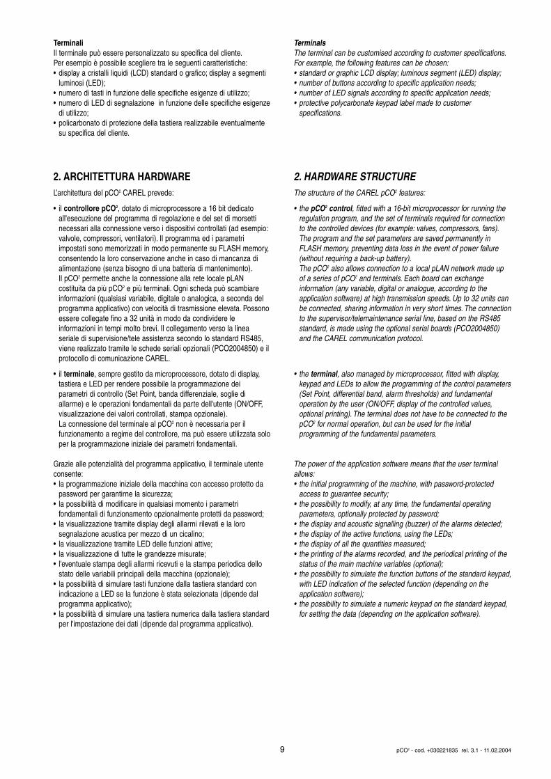
TerminaliIl terminale può essere personalizzato su specifica del cliente.Per esempio è possibile scegliere tra le seguenti caratteristiche:• display a cristalli liquidi (LCD) standard o grafico; display a segmenti
luminosi (LED);• numero di tasti in funzione delle specifiche esigenze di utilizzo;• numero di LED di segnalazione in funzione delle specifiche esigenze
di utilizzo;• policarbonato di protezione della tastiera realizzabile eventualmente
su specifica del cliente.
2. ARCHITETTURA HARDWAREL’architettura del pCO2 CAREL prevede:
• il controllore pCO2, dotato di microprocessore a 16 bit dedicato all'esecuzione del programma di regolazione e del set di morsetti necessari alla connessione verso i dispositivi controllati (ad esempio:valvole, compressori, ventilatori). Il programma ed i parametri impostati sono memorizzati in modo permanente su FLASH memory,consentendo la loro conservazione anche in caso di mancanza di alimentazione (senza bisogno di una batteria di mantenimento).Il pCO2 permette anche la connessione alla rete locale pLAN costituita da più pCO2 e più terminali. Ogni scheda può scambiare informazioni (qualsiasi variabile, digitale o analogica, a seconda del programma applicativo) con velocità di trasmissione elevata. Possonoessere collegate fino a 32 unità in modo da condividere le informazioni in tempi molto brevi. Il collegamento verso la linea seriale di supervisione/tele assistenza secondo lo standard RS485, viene realizzato tramite le schede seriali opzionali (PCO2004850) e ilprotocollo di comunicazione CAREL.
• il terminale, sempre gestito da microprocessore, dotato di display, tastiera e LED per rendere possibile la programmazione dei parametri di controllo (Set Point, banda differenziale, soglie di allarme) e le operazioni fondamentali da parte dell'utente (ON/OFF, visualizzazione dei valori controllati, stampa opzionale).La connessione del terminale al pCO2 non è necessaria per il funzionamento a regime del controllore, ma può essere utilizzata soloper la programmazione iniziale dei parametri fondamentali.
Grazie alle potenzialità del programma applicativo, il terminale utenteconsente:• la programmazione iniziale della macchina con accesso protetto da
password per garantirne la sicurezza;• la possibilità di modificare in qualsiasi momento i parametri
fondamentali di funzionamento opzionalmente protetti da password;• la visualizzazione tramite display degli allarmi rilevati e la loro
segnalazione acustica per mezzo di un cicalino;• la visualizzazione tramite LED delle funzioni attive;• la visualizzazione di tutte le grandezze misurate;• l'eventuale stampa degli allarmi ricevuti e la stampa periodica dello
stato delle variabili principali della macchina (opzionale);• la possibilità di simulare tasti funzione dalla tastiera standard con
indicazione a LED se la funzione è stata selezionata (dipende dal programma applicativo);
• la possibilità di simulare una tastiera numerica dalla tastiera standardper l'impostazione dei dati (dipende dal programma applicativo).
TerminalsThe terminal can be customised according to customer specifications.For example, the following features can be chosen:• standard or graphic LCD display; luminous segment (LED) display;• number of buttons according to specific application needs;• number of LED signals according to specific application needs;• protective polycarbonate keypad label made to customer
specifications.
2. HARDWARE STRUCTUREThe structure of the CAREL pCO2 features:
• the pCO2 control, fitted with a 16-bit microprocessor for running the regulation program, and the set of terminals required for connection to the controlled devices (for example: valves, compressors, fans).The program and the set parameters are saved permanently in FLASH memory, preventing data loss in the event of power failure (without requiring a back-up battery).The pCO2 also allows connection to a local pLAN network made up of a series of pCO2 and terminals. Each board can exchange information (any variable, digital or analogue, according to the application software) at high transmission speeds. Up to 32 units can be connected, sharing information in very short times. The connectionto the supervisor/telemaintenance serial line, based on the RS485 standard, is made using the optional serial boards (PCO2004850) and the CAREL communication protocol.
• the terminal, also managed by microprocessor, fitted with display, keypad and LEDs to allow the programming of the control parameters(Set Point, differential band, alarm thresholds) and fundamental operation by the user (ON/OFF, display of the controlled values, optional printing). The terminal does not have to be connected to the pCO2 for normal operation, but can be used for the initial programming of the fundamental parameters.
The power of the application software means that the user terminalallows:• the initial programming of the machine, with password-protected
access to guarantee security;• the possibility to modify, at any time, the fundamental operating
parameters, optionally protected by password;• the display and acoustic signalling (buzzer) of the alarms detected;• the display of the active functions, using the LEDs;• the display of all the quantities measured;• the printing of the alarms recorded, and the periodical printing of the
status of the main machine variables (optional);• the possibility to simulate the function buttons of the standard keypad,
with LED indication of the selected function (depending on the application software);
• the possibility to simulate a numeric keypad on the standard keypad, for setting the data (depending on the application software).
9 pCO2 - cod. +030221835 rel. 3.1 - 11.02.2004
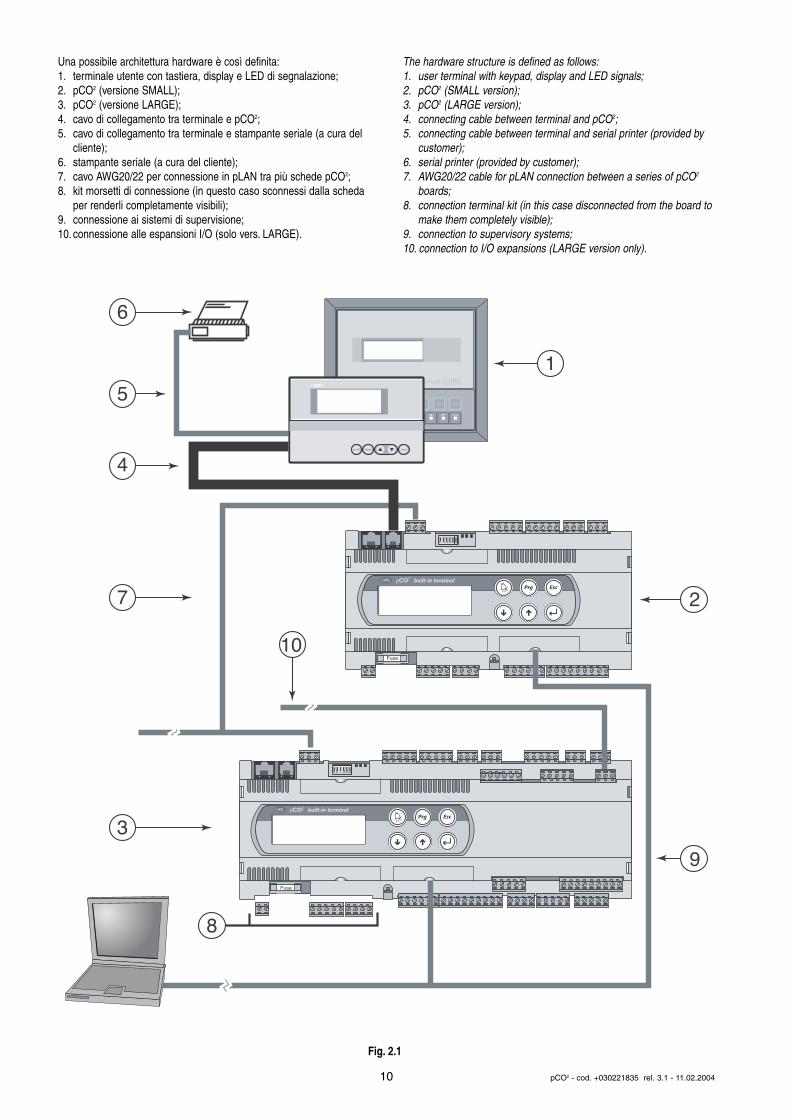
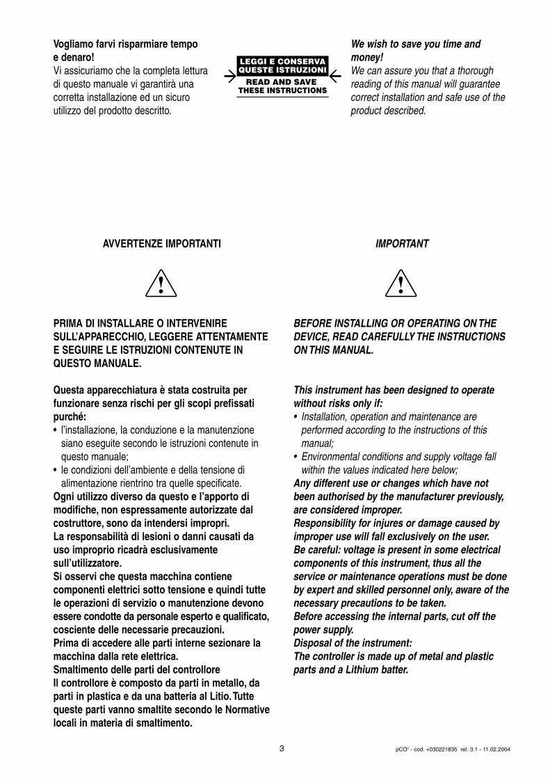
Una possibile architettura hardware è così definita:1. terminale utente con tastiera, display e LED di segnalazione;2. pCO2 (versione SMALL);3. pCO2 (versione LARGE);4. cavo di collegamento tra terminale e pCO2;5. cavo di collegamento tra terminale e stampante seriale (a cura del
cliente);6. stampante seriale (a cura del cliente);7. cavo AWG20/22 per connessione in pLAN tra più schede pCO2;8. kit morsetti di connessione (in questo caso sconnessi dalla scheda
per renderli completamente visibili);9. connessione ai sistemi di supervisione;10. connessione alle espansioni I/O (solo vers. LARGE).
The hardware structure is defined as follows:1. user terminal with keypad, display and LED signals;2. pCO2 (SMALL version);3. pCO2 (LARGE version);4. connecting cable between terminal and pCO2;5. connecting cable between terminal and serial printer (provided by
customer);6. serial printer (provided by customer);7. AWG20/22 cable for pLAN connection between a series of pCO2
boards;8. connection terminal kit (in this case disconnected from the board to
make them completely visible);9. connection to supervisory systems;10. connection to I/O expansions (LARGE version only).
10 pCO2 - cod. +030221835 rel. 3.1 - 11.02.2004
Fuse
Fuse
8
3
1
10
7
4
5
6
9
2
set prog.
enter
Terminal
on/off alarm enter
built-in terminal
built-in terminal
Fig. 2.1
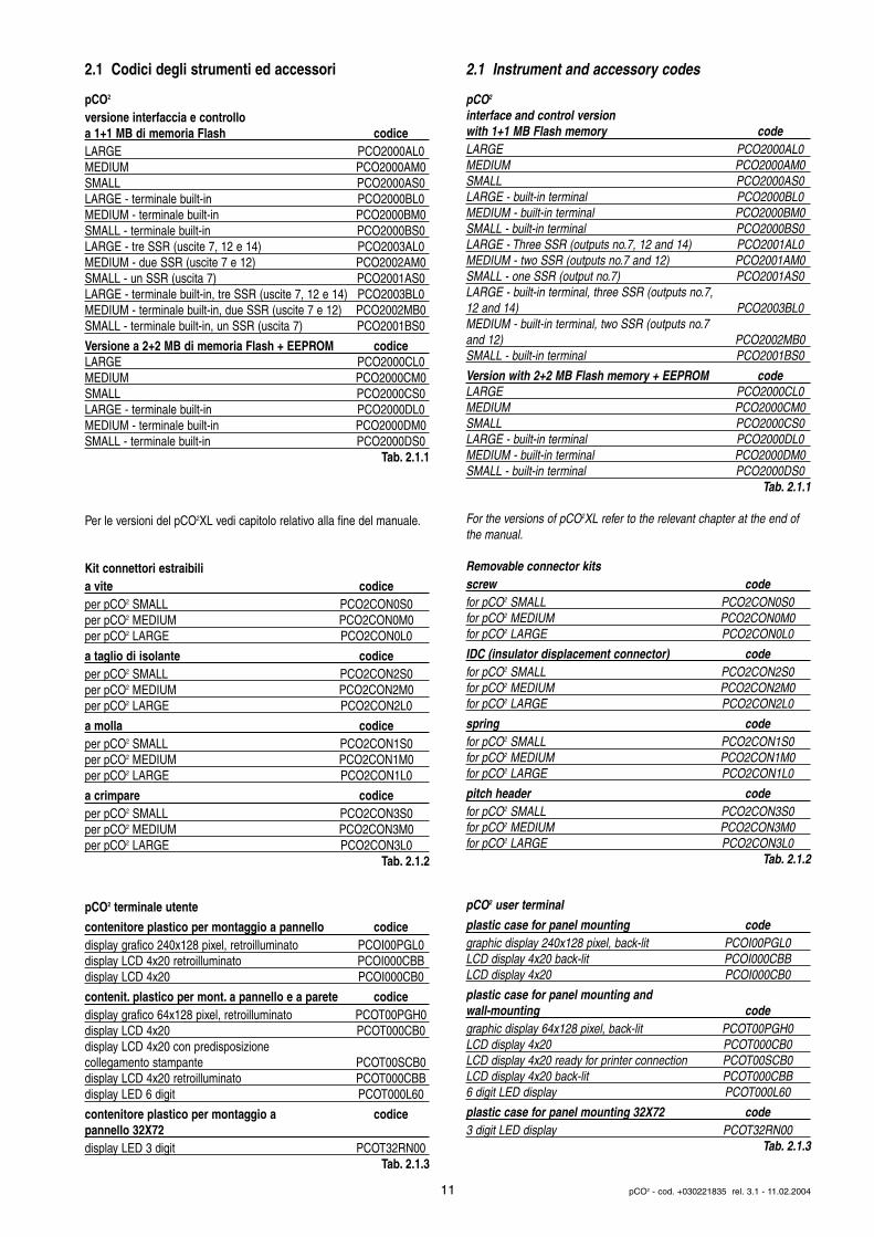
2.1 Codici degli strumenti ed accessori
pCO2
versione interfaccia e controllo a 1+1 MB di memoria Flash codiceLARGE PCO2000AL0MEDIUM PCO2000AM0SMALL PCO2000AS0LARGE - terminale built-in PCO2000BL0MEDIUM - terminale built-in PCO2000BM0SMALL - terminale built-in PCO2000BS0LARGE - tre SSR (uscite 7, 12 e 14) PCO2003AL0MEDIUM - due SSR (uscite 7 e 12) PCO2002AM0SMALL - un SSR (uscita 7) PCO2001AS0LARGE - terminale built-in, tre SSR (uscite 7, 12 e 14) PCO2003BL0MEDIUM - terminale built-in, due SSR (uscite 7 e 12) PCO2002MB0SMALL - terminale built-in, un SSR (uscita 7) PCO2001BS0
Versione a 2+2 MB di memoria Flash + EEPROM codiceLARGE PCO2000CL0MEDIUM PCO2000CM0SMALL PCO2000CS0LARGE - terminale built-in PCO2000DL0MEDIUM - terminale built-in PCO2000DM0SMALL - terminale built-in PCO2000DS0
Tab. 2.1.1
Per le versioni del pCO2XL vedi capitolo relativo alla fine del manuale.
Kit connettori estraibilia vite codiceper pCO2 SMALL PCO2CON0S0per pCO2 MEDIUM PCO2CON0M0per pCO2 LARGE PCO2CON0L0
a taglio di isolante codiceper pCO2 SMALL PCO2CON2S0per pCO2 MEDIUM PCO2CON2M0per pCO2 LARGE PCO2CON2L0
a molla codiceper pCO2 SMALL PCO2CON1S0per pCO2 MEDIUM PCO2CON1M0per pCO2 LARGE PCO2CON1L0
a crimpare codiceper pCO2 SMALL PCO2CON3S0per pCO2 MEDIUM PCO2CON3M0per pCO2 LARGE PCO2CON3L0
Tab. 2.1.2
pCO2 terminale utente
contenitore plastico per montaggio a pannello codicedisplay grafico 240x128 pixel, retroilluminato PCOI00PGL0display LCD 4x20 retroilluminato PCOI000CBBdisplay LCD 4x20 PCOI000CB0
contenit. plastico per mont. a pannello e a parete codicedisplay grafico 64x128 pixel, retroilluminato PCOT00PGH0display LCD 4x20 PCOT000CB0display LCD 4x20 con predisposizione collegamento stampante PCOT00SCB0display LCD 4x20 retroilluminato PCOT000CBBdisplay LED 6 digit PCOT000L60
contenitore plastico per montaggio a codicepannello 32X72display LED 3 digit PCOT32RN00
Tab. 2.1.3
2.1 Instrument and accessory codes
pCO2
interface and control version with 1+1 MB Flash memory codeLARGE PCO2000AL0MEDIUM PCO2000AM0SMALL PCO2000AS0LARGE - built-in terminal PCO2000BL0MEDIUM - built-in terminal PCO2000BM0SMALL - built-in terminal PCO2000BS0LARGE - Three SSR (outputs no.7, 12 and 14) PCO2001AL0MEDIUM - two SSR (outputs no.7 and 12) PCO2001AM0SMALL - one SSR (output no.7) PCO2001AS0LARGE - built-in terminal, three SSR (outputs no.7, 12 and 14) PCO2003BL0MEDIUM - built-in terminal, two SSR (outputs no.7 and 12) PCO2002MB0SMALL - built-in terminal PCO2001BS0
Version with 2+2 MB Flash memory + EEPROM codeLARGE PCO2000CL0MEDIUM PCO2000CM0SMALL PCO2000CS0LARGE - built-in terminal PCO2000DL0MEDIUM - built-in terminal PCO2000DM0SMALL - built-in terminal PCO2000DS0
Tab. 2.1.1
For the versions of pCO2XL refer to the relevant chapter at the end ofthe manual.
Removable connector kitsscrew codefor pCO2 SMALL PCO2CON0S0for pCO2 MEDIUM PCO2CON0M0for pCO2 LARGE PCO2CON0L0
IDC (insulator displacement connector) codefor pCO2 SMALL PCO2CON2S0for pCO2 MEDIUM PCO2CON2M0for pCO2 LARGE PCO2CON2L0
spring codefor pCO2 SMALL PCO2CON1S0for pCO2 MEDIUM PCO2CON1M0for pCO2 LARGE PCO2CON1L0
pitch header codefor pCO2 SMALL PCO2CON3S0for pCO2 MEDIUM PCO2CON3M0for pCO2 LARGE PCO2CON3L0
Tab. 2.1.2
pCO2 user terminal
plastic case for panel mounting codegraphic display 240x128 pixel, back-lit PCOI00PGL0LCD display 4x20 back-lit PCOI000CBBLCD display 4x20 PCOI000CB0
plastic case for panel mounting and wall-mounting codegraphic display 64x128 pixel, back-lit PCOT00PGH0LCD display 4x20 PCOT000CB0LCD display 4x20 ready for printer connection PCOT00SCB0LCD display 4x20 back-lit PCOT000CBB6 digit LED display PCOT000L60
plastic case for panel mounting 32X72 code3 digit LED display PCOT32RN00
Tab. 2.1.3
11 pCO2 - cod. +030221835 rel. 3.1 - 11.02.2004
Cavi di collegamento terminale utente/interfaccialunghezza (m) tipo codice
0,8 connettori telefonici S90CONN0021,5 connettori telefonici S90CONN0003 connettori telefonici S90CONN0016 connettori telefonici S90CONN003
Tab. 2.1.4
Remotazione terminaleaccessori per i collegamenti elettrici codicescheda per remotazione terminale utente TCONN6J000
Tab. 2.1.5
Schede opzionaliopzioni codicesch. collegamento ser. RS485 optoisolata per pCO2 PCO2004850scheda collegamento seriale RS232 per modem, non optoisolata per pCO2 PCO200MDM0scheda interfaccia stampante per display grafico PCOSERPRN0scheda controllo umidificatore a vapore CAREL OEM PCOUMID000nuova scheda controllo umidificatore a vapore CAREL OEM in 4 moduli DIN PCOUMID200scheda espansione flash memory per pCO2 PCO200MEM0scheda chiave di programmazione per pCO2 da 1MB PCO201KEY0scheda chiave di programmazione per pCO2 da 2MB PCO202KEY0seriale Lon FTT10 PCO20000F0seriale Lon RS485 PCO20000R0modulo DC/DC PCO20DCDC0
Tab. 2.1.6
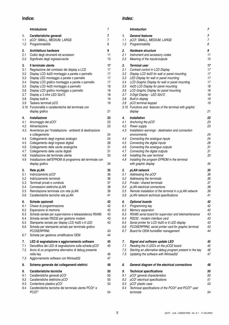
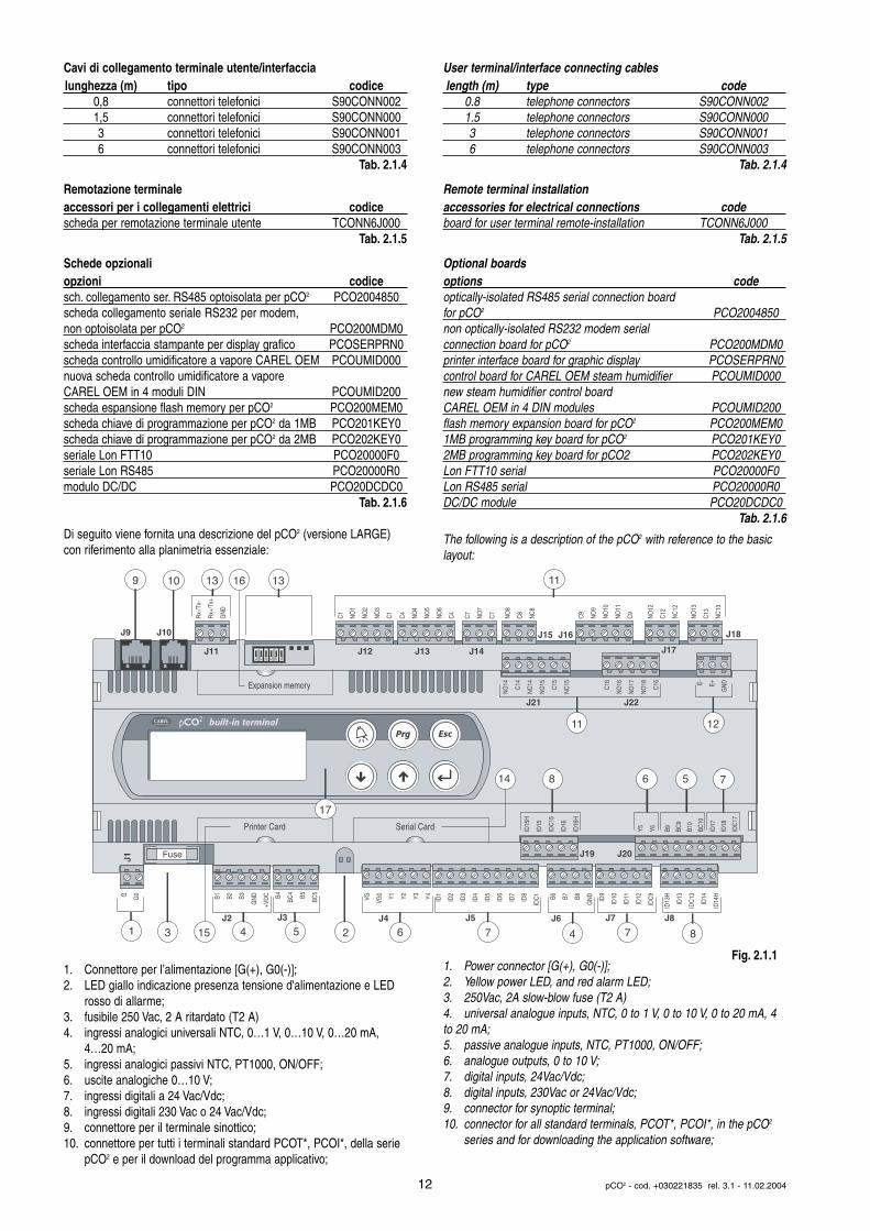
Di seguito viene fornita una descrizione del pCO2 (versione LARGE)con riferimento alla planimetria essenziale:
1. Connettore per l’alimentazione [G(+), G0(-)];2. LED giallo indicazione presenza tensione d'alimentazione e LED
rosso di allarme;3. fusibile 250 Vac, 2 A ritardato (T2 A)4. ingressi analogici universali NTC, 0…1 V, 0…10 V, 0…20 mA,
4…20 mA;5. ingressi analogici passivi NTC, PT1000, ON/OFF;6. uscite analogiche 0…10 V;7. ingressi digitali a 24 Vac/Vdc;8. ingressi digitali 230 Vac o 24 Vac/Vdc;9. connettore per il terminale sinottico;10. connettore per tutti i terminali standard PCOT*, PCOI*, della serie
pCO2 e per il download del programma applicativo;
User terminal/interface connecting cableslength (m) type code
0.8 telephone connectors S90CONN0021.5 telephone connectors S90CONN0003 telephone connectors S90CONN0016 telephone connectors S90CONN003
Tab. 2.1.4
Remote terminal installationaccessories for electrical connections codeboard for user terminal remote-installation TCONN6J000
Tab. 2.1.5
Optional boardsoptions codeoptically-isolated RS485 serial connection board for pCO2 PCO2004850non optically-isolated RS232 modem serial connection board for pCO2 PCO200MDM0printer interface board for graphic display PCOSERPRN0control board for CAREL OEM steam humidifier PCOUMID000new steam humidifier control boardCAREL OEM in 4 DIN modules PCOUMID200flash memory expansion board for pCO2 PCO200MEM01MB programming key board for pCO2 PCO201KEY02MB programming key board for pCO2 PCO202KEY0Lon FTT10 serial PCO20000F0Lon RS485 serial PCO20000R0DC/DC module PCO20DCDC0
Tab. 2.1.6
The following is a description of the pCO2 with reference to the basiclayout:
1. Power connector [G(+), G0(-)];2. Yellow power LED, and red alarm LED;3. 250Vac, 2A slow-blow fuse (T2 A)4. universal analogue inputs, NTC, 0 to 1 V, 0 to 10 V, 0 to 20 mA, 4to 20 mA;5. passive analogue inputs, NTC, PT1000, ON/OFF;6. analogue outputs, 0 to 10 V;7. digital inputs, 24Vac/Vdc;8. digital inputs, 230Vac or 24Vac/Vdc;9. connector for synoptic terminal;10. connector for all standard terminals, PCOT*, PCOI*, in the pCO2
series and for downloading the application software;
12 pCO2 - cod. +030221835 rel. 3.1 - 11.02.2004
Fuse
Expansion memory
built-in terminal
Rx-
/Tx-
Rx+
/Tx+
GN
D
C1
NO
1
NO
2
NO
3
C1
C4
NO
4
NO
5
NO
6
C4
C7
NO
7
C7
NO
8
C8
NC
8
NO
12
C12
NC
12
NO
13
C13
NC
13
C9
NO
9
NO
10
NO
11
C9
G G0 B1 B2 B3
GN
D
+VD
C B4
BC4 B5
BC5
VG VG0 Y1 Y2 Y3 Y4 ID1
ID2
ID3
ID4
ID5
ID6
ID7
ID8
IDC
1 B6 B7 B8
GN
D
ID9
ID10
ID11
ID12
IDC
9
ID13
H
ID13
IDC
13
ID14
ID14
H
J1
J2 J3 J5 J6
J19
J7 J8
J11 J12 J13 J14
J15 J16
J17
J18J9 J10
J4
10
1 3 7 74 46
NO
14
C14
NC
14
NO
15
C15
NC
15
C16
NO
16
NO
17
NO
18
C16 E- E+
GN
D
J21 J22
8
9
2
13
ID15
H
ID15
IDC
15
ID16
ID16
H
Y5 Y6 ID17
ID18
IDC
17
J20
B9 BC9
B10
BC10
16 13
14
17
15
Printer Card Serial Card
11
11
12
6 78
5
5
Fig. 2.1.1
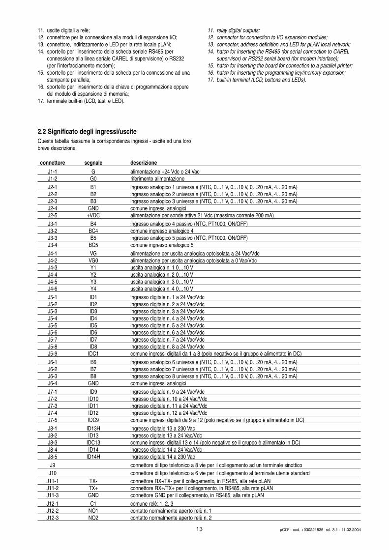
11. uscite digitali a relè;12. connettore per la connessione alla moduli di espansione I/O;13. connettore, indirizzamento e LED per la rete locale pLAN;14. sportello per l’inserimento della scheda seriale RS485 (per
connessione alla linea seriale CAREL di supervisione) o RS232 (per l’interfacciamento modem);
15. sportello per l’inserimento della scheda per la connessione ad unastampante parallela;
16. sportello per l’inserimento della chiave di programmazione oppure del modulo di espansione di memoria;
17. terminale built-in (LCD, tasti e LED).
2.2 Significato degli ingressi/usciteQuesta tabella riassume la corrispondenza ingressi - uscite ed una lorobreve descrizione.
11. relay digital outputs;12. connector for connection to I/O expansion modules;13. connector, address definition and LED for pLAN local network;14. hatch for inserting the RS485 (for serial connection to CAREL
supervisor) or RS232 serial board (for modem interface);15. hatch for inserting the board for connection to a parallel printer;16. hatch for inserting the programming key/memory expansion;17. built-in terminal (LCD, buttons and LEDs).
13 pCO2 - cod. +030221835 rel. 3.1 - 11.02.2004
connettore segnale descrizione
J1-1 G alimentazione +24 Vdc o 24 VacJ1-2 G0 riferimento alimentazioneJ2-1 B1 ingresso analogico 1 universale (NTC, 0…1 V, 0…10 V, 0…20 mA, 4…20 mA)J2-2 B2 ingresso analogico 2 universale (NTC, 0…1 V, 0…10 V, 0…20 mA, 4…20 mA)J2-3 B3 ingresso analogico 3 universale (NTC, 0…1 V, 0…10 V, 0…20 mA, 4…20 mA)J2-4 GND comune ingressi analogiciJ2-5 +VDC alimentazione per sonde attive 21 Vdc (massima corrente 200 mA)J3-1 B4 ingresso analogico 4 passivo (NTC, PT1000, ON/OFF)J3-2 BC4 comune ingresso analogico 4J3-3 B5 ingresso analogico 5 passivo (NTC, PT1000, ON/OFF)J3-4 BC5 comune ingresso analogico 5J4-1 VG alimentazione per uscita analogica optoisolata a 24 Vac/VdcJ4-2 VG0 alimentazione per uscita analogica optoisolata a 0 Vac/VdcJ4-3 Y1 uscita analogica n. 1 0…10 VJ4-4 Y2 uscita analogica n. 2 0…10 VJ4-5 Y3 uscita analogica n. 3 0…10 VJ4-6 Y4 uscita analogica n. 4 0…10 VJ5-1 ID1 ingresso digitale n. 1 a 24 Vac/VdcJ5-2 ID2 ingresso digitale n. 2 a 24 Vac/VdcJ5-3 ID3 ingresso digitale n. 3 a 24 Vac/VdcJ5-4 ID4 ingresso digitale n. 4 a 24 Vac/VdcJ5-5 ID5 ingresso digitale n. 5 a 24 Vac/VdcJ5-6 ID6 ingresso digitale n. 6 a 24 Vac/VdcJ5-7 ID7 ingresso digitale n. 7 a 24 Vac/VdcJ5-8 ID8 ingresso digitale n. 8 a 24 Vac/VdcJ5-9 IDC1 comune ingressi digitali da 1 a 8 (polo negativo se il gruppo è alimentato in DC)J6-1 B6 ingresso analogico 6 universale (NTC, 0…1 V, 0…10 V, 0…20 mA, 4…20 mA)J6-2 B7 ingresso analogico 7 universale (NTC, 0…1 V, 0…10 V, 0…20 mA, 4…20 mA)J6-3 B8 ingresso analogico 8 universale (NTC, 0…1 V, 0…10 V, 0…20 mA, 4…20 mA)J6-4 GND comune ingressi analogiciJ7-1 ID9 ingresso digitale n. 9 a 24 Vac/VdcJ7-2 ID10 ingresso digitale n. 10 a 24 Vac/VdcJ7-3 ID11 ingresso digitale n. 11 a 24 Vac/VdcJ7-4 ID12 ingresso digitale n. 12 a 24 Vac/VdcJ7-5 IDC9 comune ingressi digitali da 9 a 12 (polo negativo se il gruppo è alimentato in DC)J8-1 ID13H ingresso digitale 13 a 230 VacJ8-2 ID13 ingresso digitale 13 a 24 Vac/VdcJ8-3 IDC13 comune ingressi digitali 13 e 14 (polo negativo se il gruppo è alimentato in DC)J8-4 ID14 ingresso digitale 14 a 24 Vac/VdcJ8-5 ID14H ingresso digitale 14 a 230 VacJ9 connettore di tipo telefonico a 8 vie per il collegamento ad un terminale sinottico J10 connettore di tipo telefonico a 6 vie per il collegamento al terminale utente standard
J11-1 TX- connettore RX-/TX- per il collegamento, in RS485, alla rete pLANJ11-2 TX+ connettore RX+/TX+ per il collegamento, in RS485, alla rete pLANJ11-3 GND connettore GND per il collegamento, in RS485, alla rete pLANJ12-1 C1 comune relè: 1, 2, 3J12-2 NO1 contatto normalmente aperto relè n. 1J12-3 NO2 contatto normalmente aperto relè n. 2
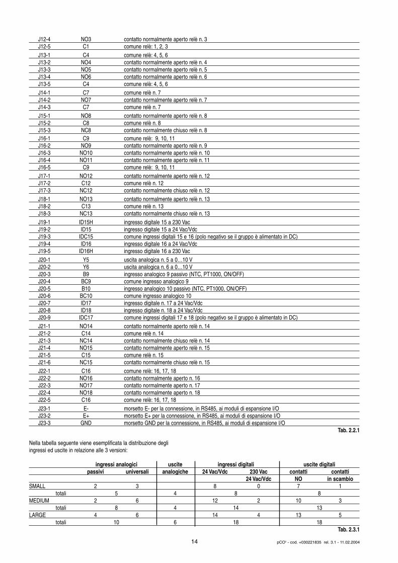
Nella tabella seguente viene esemplificata la distribuzione degli ingressi ed uscite in relazione alle 3 versioni:
14 pCO2 - cod. +030221835 rel. 3.1 - 11.02.2004
J12-4 NO3 contatto normalmente aperto relè n. 3J12-5 C1 comune relè: 1, 2, 3J13-1 C4 comune relè: 4, 5, 6J13-2 NO4 contatto normalmente aperto relè n. 4J13-3 NO5 contatto normalmente aperto relè n. 5J13-4 NO6 contatto normalmente aperto relè n. 6J13-5 C4 comune relè: 4, 5, 6J14-1 C7 comune relè n. 7J14-2 NO7 contatto normalmente aperto relè n. 7J14-3 C7 comune relè n. 7J15-1 NO8 contatto normalmente aperto relè n. 8J15-2 C8 comune relè n. 8J15-3 NC8 contatto normalmente chiuso relè n. 8J16-1 C9 comune relè: 9, 10, 11J16-2 NO9 contatto normalmente aperto relè n. 9J16-3 NO10 contatto normalmente aperto relè n. 10J16-4 NO11 contatto normalmente aperto relè n. 11J16-5 C9 comune relè: 9, 10, 11J17-1 NO12 contatto normalmente aperto relè n. 12J17-2 C12 comune relè n. 12J17-3 NC12 contatto normalmente chiuso relè n. 12J18-1 NO13 contatto normalmente aperto relè n. 13J18-2 C13 comune relè n. 13J18-3 NC13 contatto normalmente chiuso relè n. 13J19-1 ID15H ingresso digitale 15 a 230 VacJ19-2 ID15 ingresso digitale 15 a 24 Vac/VdcJ19-3 IDC15 comune ingressi digitali 15 e 16 (polo negativo se il gruppo è alimentato in DC)J19-4 ID16 ingresso digitale 16 a 24 Vac/VdcJ19-5 ID16H ingresso digitale 16 a 230 VacJ20-1 Y5 uscita analogica n. 5 a 0…10 VJ20-2 Y6 uscita analogica n. 6 a 0…10 VJ20-3 B9 ingresso analogico 9 passivo (NTC, PT1000, ON/OFF)J20-4 BC9 comune ingresso analogico 9J20-5 B10 ingresso analogico 10 passivo (NTC, PT1000, ON/OFF)J20-6 BC10 comune ingresso analogico 10J20-7 ID17 ingresso digitale n. 17 a 24 Vac/VdcJ20-8 ID18 ingresso digitale n. 18 a 24 Vac/VdcJ20-9 IDC17 comune ingressi digitali 17 e 18 (polo negativo se il gruppo è alimentato in DC)J21-1 NO14 contatto normalmente aperto relè n. 14J21-2 C14 comune relè n. 14J21-3 NC14 contatto normalmente chiuso relè n. 14J21-4 NO15 contatto normalmente aperto relè n. 15J21-5 C15 comune relè n. 15J21-6 NC15 contatto normalmente chiuso relè n. 15J22-1 C16 comune relè: 16, 17, 18J22-2 NO16 contatto normalmente aperto n. 16J22-3 NO17 contatto normalmente aperto n. 17J22-4 NO18 contatto normalmente aperto n. 18J22-5 C16 comune relè: 16, 17, 18J23-1 E- morsetto E- per la connessione, in RS485, ai moduli di espansione I/OJ23-2 E+ morsetto E+ per la connessione, in RS485, ai moduli di espansione I/OJ23-3 GND morsetto GND per la connessione, in RS485, ai moduli di espansione I/O
Tab. 2.2.1
ingressi analogici uscite ingressi digitali uscite digitalipassivi universali analogiche 24 Vac/Vdc 230 Vac contatti contatti
24 Vac/Vdc NO in scambioSMALL 2 3 8 0 7 1
totali 5 4 8 8MEDIUM 2 6 12 2 10 3
totali 8 4 14 13LARGE 4 6 14 4 13 5
totali 10 6 18 18Tab. 2.3.1
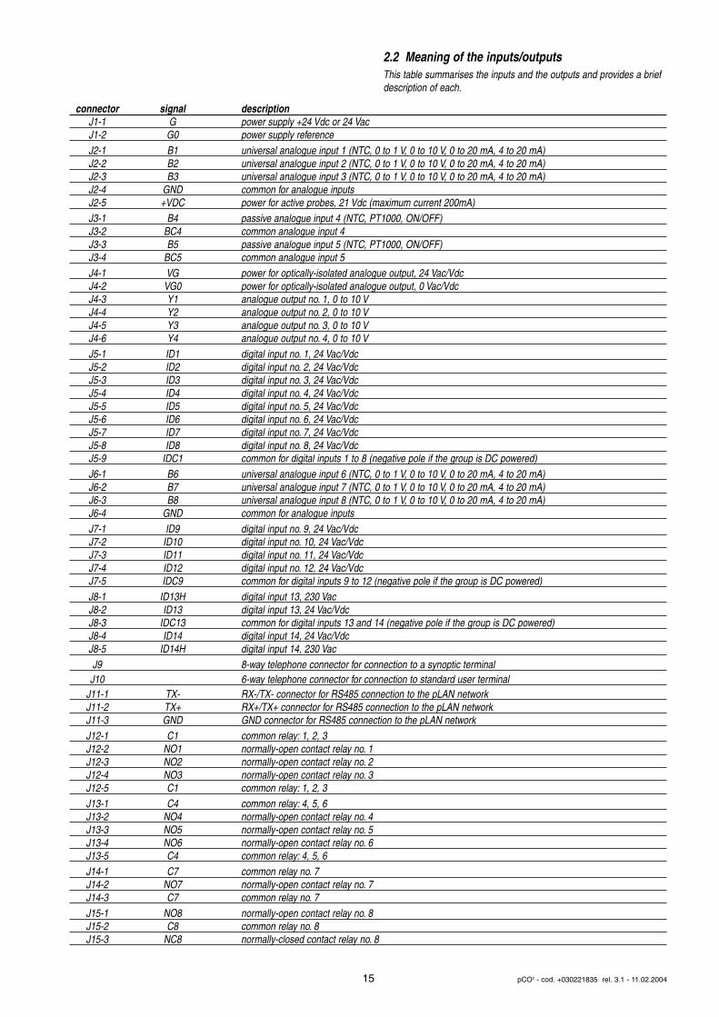
2.2 Meaning of the inputs/outputsThis table summarises the inputs and the outputs and provides a briefdescription of each.
15 pCO2 - cod. +030221835 rel. 3.1 - 11.02.2004
connector signal descriptionJ1-1 G power supply +24 Vdc or 24 VacJ1-2 G0 power supply referenceJ2-1 B1 universal analogue input 1 (NTC, 0 to 1 V, 0 to 10 V, 0 to 20 mA, 4 to 20 mA)J2-2 B2 universal analogue input 2 (NTC, 0 to 1 V, 0 to 10 V, 0 to 20 mA, 4 to 20 mA)J2-3 B3 universal analogue input 3 (NTC, 0 to 1 V, 0 to 10 V, 0 to 20 mA, 4 to 20 mA)J2-4 GND common for analogue inputsJ2-5 +VDC power for active probes, 21 Vdc (maximum current 200mA)J3-1 B4 passive analogue input 4 (NTC, PT1000, ON/OFF)J3-2 BC4 common analogue input 4J3-3 B5 passive analogue input 5 (NTC, PT1000, ON/OFF)J3-4 BC5 common analogue input 5J4-1 VG power for optically-isolated analogue output, 24 Vac/VdcJ4-2 VG0 power for optically-isolated analogue output, 0 Vac/VdcJ4-3 Y1 analogue output no. 1, 0 to 10 VJ4-4 Y2 analogue output no. 2, 0 to 10 VJ4-5 Y3 analogue output no. 3, 0 to 10 VJ4-6 Y4 analogue output no. 4, 0 to 10 VJ5-1 ID1 digital input no. 1, 24 Vac/VdcJ5-2 ID2 digital input no. 2, 24 Vac/VdcJ5-3 ID3 digital input no. 3, 24 Vac/VdcJ5-4 ID4 digital input no. 4, 24 Vac/VdcJ5-5 ID5 digital input no. 5, 24 Vac/VdcJ5-6 ID6 digital input no. 6, 24 Vac/VdcJ5-7 ID7 digital input no. 7, 24 Vac/VdcJ5-8 ID8 digital input no. 8, 24 Vac/VdcJ5-9 IDC1 common for digital inputs 1 to 8 (negative pole if the group is DC powered)J6-1 B6 universal analogue input 6 (NTC, 0 to 1 V, 0 to 10 V, 0 to 20 mA, 4 to 20 mA)J6-2 B7 universal analogue input 7 (NTC, 0 to 1 V, 0 to 10 V, 0 to 20 mA, 4 to 20 mA)J6-3 B8 universal analogue input 8 (NTC, 0 to 1 V, 0 to 10 V, 0 to 20 mA, 4 to 20 mA)J6-4 GND common for analogue inputsJ7-1 ID9 digital input no. 9, 24 Vac/VdcJ7-2 ID10 digital input no. 10, 24 Vac/VdcJ7-3 ID11 digital input no. 11, 24 Vac/VdcJ7-4 ID12 digital input no. 12, 24 Vac/VdcJ7-5 IDC9 common for digital inputs 9 to 12 (negative pole if the group is DC powered)J8-1 ID13H digital input 13, 230 VacJ8-2 ID13 digital input 13, 24 Vac/VdcJ8-3 IDC13 common for digital inputs 13 and 14 (negative pole if the group is DC powered)J8-4 ID14 digital input 14, 24 Vac/VdcJ8-5 ID14H digital input 14, 230 VacJ9 8-way telephone connector for connection to a synoptic terminal J10 6-way telephone connector for connection to standard user terminal
J11-1 TX- RX-/TX- connector for RS485 connection to the pLAN networkJ11-2 TX+ RX+/TX+ connector for RS485 connection to the pLAN networkJ11-3 GND GND connector for RS485 connection to the pLAN networkJ12-1 C1 common relay: 1, 2, 3J12-2 NO1 normally-open contact relay no. 1J12-3 NO2 normally-open contact relay no. 2J12-4 NO3 normally-open contact relay no. 3J12-5 C1 common relay: 1, 2, 3J13-1 C4 common relay: 4, 5, 6J13-2 NO4 normally-open contact relay no. 4J13-3 NO5 normally-open contact relay no. 5J13-4 NO6 normally-open contact relay no. 6J13-5 C4 common relay: 4, 5, 6J14-1 C7 common relay no. 7J14-2 NO7 normally-open contact relay no. 7J14-3 C7 common relay no. 7J15-1 NO8 normally-open contact relay no. 8J15-2 C8 common relay no. 8J15-3 NC8 normally-closed contact relay no. 8
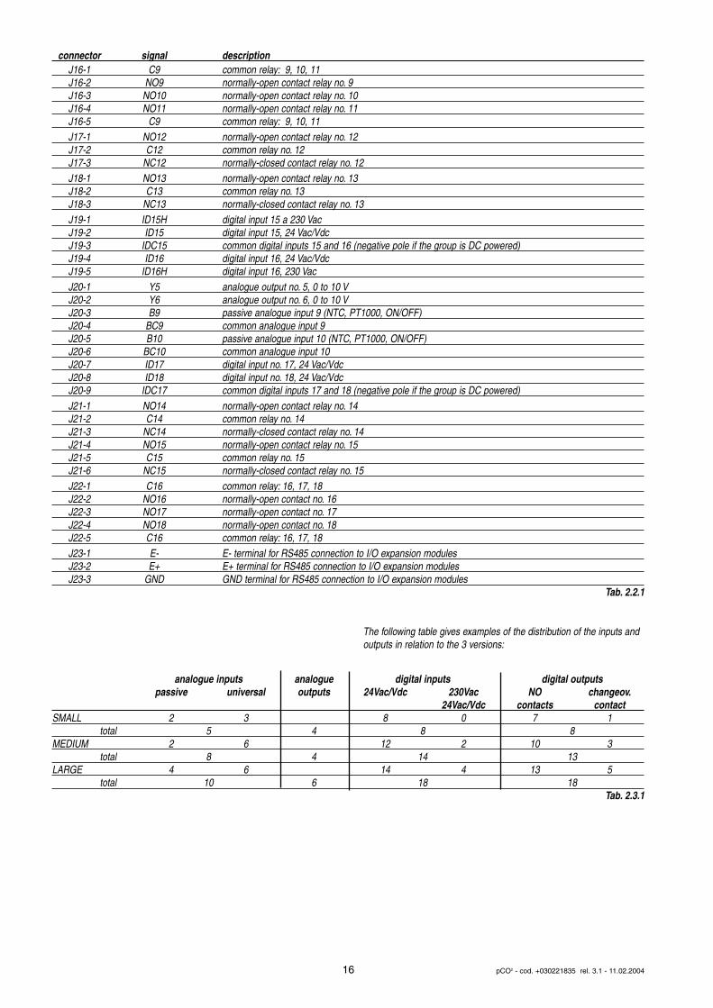
The following table gives examples of the distribution of the inputs andoutputs in relation to the 3 versions:
16 pCO2 - cod. +030221835 rel. 3.1 - 11.02.2004
J16-1 C9 common relay: 9, 10, 11J16-2 NO9 normally-open contact relay no. 9J16-3 NO10 normally-open contact relay no. 10J16-4 NO11 normally-open contact relay no. 11J16-5 C9 common relay: 9, 10, 11J17-1 NO12 normally-open contact relay no. 12J17-2 C12 common relay no. 12J17-3 NC12 normally-closed contact relay no. 12J18-1 NO13 normally-open contact relay no. 13J18-2 C13 common relay no. 13J18-3 NC13 normally-closed contact relay no. 13J19-1 ID15H digital input 15 a 230 VacJ19-2 ID15 digital input 15, 24 Vac/VdcJ19-3 IDC15 common digital inputs 15 and 16 (negative pole if the group is DC powered)J19-4 ID16 digital input 16, 24 Vac/VdcJ19-5 ID16H digital input 16, 230 VacJ20-1 Y5 analogue output no. 5, 0 to 10 VJ20-2 Y6 analogue output no. 6, 0 to 10 VJ20-3 B9 passive analogue input 9 (NTC, PT1000, ON/OFF)J20-4 BC9 common analogue input 9J20-5 B10 passive analogue input 10 (NTC, PT1000, ON/OFF)J20-6 BC10 common analogue input 10J20-7 ID17 digital input no. 17, 24 Vac/VdcJ20-8 ID18 digital input no. 18, 24 Vac/VdcJ20-9 IDC17 common digital inputs 17 and 18 (negative pole if the group is DC powered)J21-1 NO14 normally-open contact relay no. 14J21-2 C14 common relay no. 14J21-3 NC14 normally-closed contact relay no. 14J21-4 NO15 normally-open contact relay no. 15J21-5 C15 common relay no. 15J21-6 NC15 normally-closed contact relay no. 15J22-1 C16 common relay: 16, 17, 18J22-2 NO16 normally-open contact no. 16J22-3 NO17 normally-open contact no. 17J22-4 NO18 normally-open contact no. 18J22-5 C16 common relay: 16, 17, 18J23-1 E- E- terminal for RS485 connection to I/O expansion modulesJ23-2 E+ E+ terminal for RS485 connection to I/O expansion modulesJ23-3 GND GND terminal for RS485 connection to I/O expansion modules
Tab. 2.2.1
connector signal description
analogue inputs analogue digital inputs digital outputspassive universal outputs 24Vac/Vdc 230Vac NO changeov.
24Vac/Vdc contacts contactSMALL 2 3 8 0 7 1
total 5 4 8 8MEDIUM 2 6 12 2 10 3
total 8 4 14 13LARGE 4 6 14 4 13 5
total 10 6 18 18Tab. 2.3.1
3. IL TERMINALE UTENTE
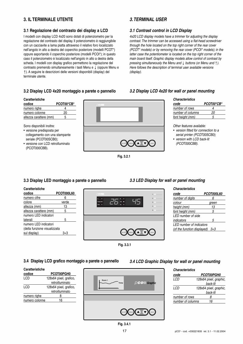
3.1 Regolazione del contrasto dei display a LCDI modelli con display LCD 4x20 sono dotati di potenziometro per laregolazione del contrasto del display. Il potenziometro è raggiungibilecon un cacciavite a lama piatta attraverso il relativo foro localizzato nell’angolo in alto a destra del coperchio posteriore (modelli PCOT*)oppure asportando il coperchio posteriore (modelli PCOI*); in questocaso il potenziometro è localizzato nell’angolo in alto a destra dellascheda. I modelli con display grafico permettono la regolazione delcontrasto premendo simultaneamente i tasti Menu e ↓ (oppure Menu e↑). A seguire le descrizioni delle versioni disponibili (display) del terminale utente.
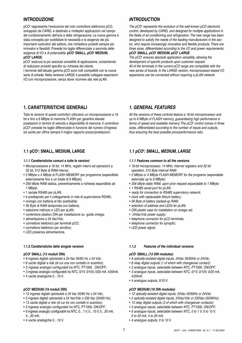
3.2 Display LCD 4x20 montaggio a parete o pannello
Caratteristichecodice PCOT00*CB*numero righe 4numero colonne 20altezza carattere (mm) 5
Sono disponibili inoltre:• versione predisposta per
collegamento con una stampante seriale (PCOT00SCB0);
• versione con LCD retroilluminato (PCOT000CBB).
3.3 Display LED montaggio a parete o pannello
Caratteristichecodice PCOT000L60numero cifre 6colore verdealtezza (mm) 13altezza carattere (mm) 5numero LED indicatori laterali 5numero LED indicatori (della funzione visualizzata sul display) 3+3
3.4 Display LCD grafico montaggio a parete o pannello
Caratteristichecodice PCOT00PGH0LCD 128x64 pixel, grafico,
retroilluminatoLCD 128x64 pixel, grafico,
retroilluminatonumero righe 8numero colonne 16
3.TERMINAL USER
3.1 Contrast control in LCD Display 4x20 LCD display models have a trimmer for adjusting the display contrast. The trimmer can be accessed using a flat-head screwdriverthrough the hole located on the top right corner of the rear cover(PCOT* models) or by removing the rear cover (PCOI* models); in thelatter case the potentiometer is located on the top right corner of themain board itself. Graphic display models allow control of contrast bypressing simultaneously the Menu and ↓ buttons (or Menu and ↑).Here follows the description of terminal user available versions(display).
3.2 Display LCD 4x20 for wall or panel mounting
Characteristicscode PCOT00*CB*number of rows 4number of columns 20font height (mm) 5
Other features available:• version fitted for connection to a
serial printer (PCOT00SCB0);• version with LCD back-lit
(PCOT000CBB).
3.3 LED Display for wall or panel mounting
Characteristicscode PCOT000L60number of digits 6colour greenheight (mm) 13font height (mm) 5LED number of side indicators 5LED number of indicators (of the function displayed) 3+3
3.4 LCD Graphic Display for wall or panel mounting
Characteristicscode PCOT00PGH0LCD 128x64 pixel, graphic,
back-litLCD 128x64 pixel, graphic,
back-litnumber of rows 8number of columns 16
17 pCO2 - cod. +030221835 rel. 3.1 - 11.02.2004
on/off alarm enter
on/off alarm enter
A____
Parem
Psw
B____
Val
AL
1_ __________
2_ __________
3_ __________
4_ __________
5_ __________
on/off alarm enter
GraphicRoom 1
Temp
Fig. 3.2.1
Fig. 3.3.1
Fig. 3.4.1
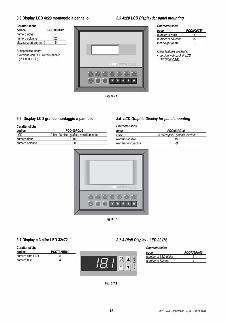
3.5 Display LCD 4x20 montaggio a pannello
Caratteristichecodice PCOI000CB*numero righe 4numero colonne 20altezza carattere (mm) 5
È disponibile inoltre:• versione con LCD retroilluminato
(PCOI000CBB).
3.6 Display LCD grafico montaggio a pannello
Caratteristichecodice PCOI00PGL0LCD 240x128 pixel, grafico, retroilluminatonumero righe 16numero colonne 30
3.7 Display a 3 cifre LED 32x72
Caratteristichecodice PCOT32RN00numero cifre LED 3numero tasti 4
3.5 4x20 LCD Display for panel mounting
Characteristicscode PCOI000CB*number of rows 4number of columns 20font height (mm) 5
Other features available:• version with back-lit LCD
(PCOI000CBB).
3.6 LCD Graphic Display for panel mounting
Characteristicscode PCOI00PGL0LCD 240x128 pixel, graphic, back-litNumber of rows 16Number of columns 30
3.7 3-Digit Display - LED 32x72
Characteristicscode PCOT32RN00number of LED digits 3number of buttons 4
18 pCO2 - cod. +030221835 rel. 3.1 - 11.02.2004
on/off alarm enter
menu I/O set prog.
?info
Terminal
on/off alarm enter
menu I/O set prog.
?info
Graphic
PRGmute
SEL
Fig. 3.5.1
Fig. 3.6.1
Fig. 3.7.1

3.8 Display built-inLe tre versioni (SMALL, MEDIUM, LARGE) prevedono una versionecon display e tastiera direttamente integrata sul contenitore plastico:
Caratteristichecodici* PCO2000BS0, PCO2000BM0, PCO2000BL0LCD 4x20, retroilluminatonumero tasti 6numero LED 4
* vedi Codici degli strumenti ed accessori.
Queste versioni con LCD e tastiera integrati supportanoanche il collegamento con tutti iterminali della serie pCO (i duedisplay, built-in e standard, lavorano contemporaneamentevisualizzando le stesse informazioni).Questa versione di terminale permette anche la regolazione del contrasto del display.Per effettuare ciò:1. premere contemporaneamente i tasti Enter ed Esc;2. tenendo premuti i due tasti, agire sul tasto Up o Down a seconda del
contrasto desiderato (rispettivamente aumento o diminuzione).
Nella tabella seguente è esposta la corrispondenza dei tasti relativamente alle tastiere del terminali built-in e standard:
tastiera built-in tastiera terminale standardtasto Alarm tasto alarmtasto Prg tasto prgtasto Esc tasto menutasto up tasto up
tasto down tasto downtasto enter tasto enter
Tab. 3.7.1
Nella tastiera con terminale built-in la pressione contemporanea deitasti up-down-enter permette all'utente di effettuare un controllo rapidodegli ingressi e delle uscite.
3.9 Tastiera terminali pCO
n. descrizione1 tasti meccanici coperti da policarbonato2 LED indicatori funzione3 policarbonato adesivo eventualmente personalizzabile4 tasti in gomma siliconica
3.8 Built-in displayThe three versions (SMALL, MEDIUM, LARGE) feature a version withdisplay and keypad directly built into the plastic case:
Characteristicscode PCO2000BS0, PCO2000BM0,PCO2000BL0LCD 4x20, back-litno. of buttons 6no. of LEDs 4
* see Instruments and Accessories codes.
These versions with LCD andbuilt-in keypad also support connection to all the terminals inthe pCO series (the two displays,built-in and standard, worktogether, showing the same information at the same time).
This terminal version also allows the contrast of the display to be adjusted.To do this:1. press Enter and Esc together;2. keep the two buttons pressed, and use the Up or Down button to
adjust the contrast (increase or decrease respectively).
The table below shows the function of the buttons relative to the keypads on the built-in and standard terminals:
built-in keypad standard terminal keypadAlarm button alarm buttonPrg button prg buttonEsc button menu buttonup button up button
down button down buttonenter button enter button
Tab. 3.8.2
On the built-in terminal keypad pressing the up-down-enter buttonstogether allows the user to quickly check the inputs and outputs.
3.9 pCO terminal keypad
n. description1 mechanical buttons protected by polycarbonate cover2 function-indicator LEDs3 polycarbonate label (customisable)4 external rubber buttons
19 pCO2 - cod. +030221835 rel. 3.1 - 11.02.2004
built-in terminal
A____
Parem
Psw
B____
Val
AL
1_ __________
2_ __________
3_ __________
4_ __________
5_ __________
on/off enteralarm
2
1 3
menu
?info
I/O set prog.
4
COp
CO
p
Fig. 3.8.1
Fig. 3.9.1
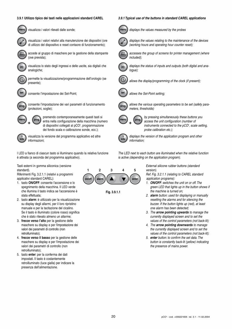
3.9.1 Utilizzo tipico dei tasti nelle applicazioni standard CAREL
visualizza i valori rilevati dalle sonde;
visualizza i valori relativi alla manutenzione dei dispositivi (oredi utilizzo del dispositivo e reset contaore di funzionamento);
accede al gruppo di maschere per la gestione della stampante(ove prevista);
visualizza lo stato degli ingressi e delle uscite, sia digitali cheanalogiche;
permette la visualizzazione/programmazione dell’orologio (sepresente);
consente l’impostazione dei Set-Point;
consente l’impostazione dei vari parametri di funzionamento(protezioni, soglie);
premendo contemporaneamente questi tasti sientra nella configurazione della macchina (numerodi dispositivi collegati al pCO2, programmazionedei fondo scala e calibrazione sonde, ecc.);
visualizza la versione del programma applicativo ed altre informazioni;
I LED a fianco di ciascun tasto si illuminano quando la relativa funzioneè attivata (a seconda del programma applicativo).
Tasti esterni in gomma siliconica (versione standard).Riferimenti Fig. 3.2.1.1 (relativi a programmiapplicativi standard CAREL):1. tasto ON/OFF: consente l'accensione e lo
spegnimento della macchina. Il LED verde che illumina il tasto indica se l'accensione è stata effettuata;
2. tasto alarm: è utilizzato per la visualizzazionesu display degli allarmi, per il loro ripristino manuale e per la tacitazione del cicalino.Se il tasto è illuminato (colore rosso) significache è stato rilevato almeno un allarme;
3. frecce verso l’alto per la gestione delle maschere su display e per l'impostazione dei valori dei parametri di controllo (non retroilluminato);
4. frecce verso il basso per la gestione delle maschere su display e per l'impostazione dei valori dei parametri di controllo (non retroilluminato);
5. tasto enter: per la conferma dei dati impostati. Il tasto è costantemente retroilluminato (luce gialla) per indicare la presenza dell’alimentazione.
3.9.1 Typical use of the buttons in standard CAREL applications
displays the values measured by the probes
displays the values relating to the maintenance of the devices(working hours and operating hour counter reset);
accesses the group of screens for printer management (whereincluded);
displays the status of inputs and outputs (both digital and ana-logue);
allows the display/programming of the clock (if present);
allows the Set-Point setting;
allows the various operating parameters to be set (safety para-meters, thresholds)
by pressing simultaneously these buttons youaccess the unit configuration (number of instruments connected to the pCO2, scale setting,probe calibration etc.);
displays the version of the application program and other information;
The LED next to each button are illuminated when the relative functionis active (depending on the application program).
External silicone rubber buttons (standard version).Ref. Fig. 3.2.1.1 (relating to CAREL standard application programs):1. ON/OFF: switches the unit on or off. The
green LED that lights up in the button shows ifthe machine is turned on;
2. alarm button: used for displaying or manually resetting the alarms and for silencing the buzzer. If the button lights up (red), at least one alarm has been detected;
3. The arrow pointing upwards to manage the currently displayed screen and to set the values of the control parameters (not back-lit);
4. The arrow pointing downwards to manage the currently displayed screen and to set the values of the control parameters (not back-lit);
5. enter button: to confirm the set data. The button is constantly back-lit (yellow) indicating the presence of mains power.
20 pCO2 - cod. +030221835 rel. 3.1 - 11.02.2004
menu
menu
prog.
?info
prog.
set
I/O
+
menu
menu
prog.
?info
prog.
set
I/O
+
on/off enteralarm
1 2 3 4 5
Fig. 3.9.1.1
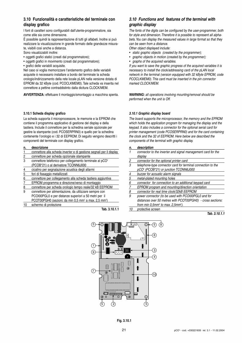
3.10 Funzionalità e caratteristiche del terminale condisplay graficoI font di caratteri sono configurabili dall’utente-programmatore, siacome stile sia come dimensione.È possibile quindi la rappresentazione di tutti gli alfabeti. Inoltre si puòrealizzare la visualizzazione in grande formato delle grandezze misura-te, visibili così anche a distanza.Sono visualizzabili inoltre:• oggetti grafici statici (creati dal programmatore);• oggetti grafici in movimento (creati dal programmatore);• grafici delle variabili acquisite.Nel caso si voglia memorizzare l’andamento grafico delle variabiliacquisite è necessario installare a bordo del terminale la scheda orologio/indirizzamento della rete locale pLAN nella versione dotata diEPROM da 32 kByte (cod. PCOCLKMEM0). Tale scheda va inserita nelconnettore a pettine contraddistinto dalla dicitura CLOCK/MEM.
AVVERTENZA: effettuare il montaggio/smontaggio a macchina spenta.
3.10.1 Scheda display graficoLa scheda supporta il microprocessore, le memorie e la EPROM checontiene il programma applicativo di gestione del display e della tastiera. Include il connettore per la schedina seriale opzionale pergestire la stampante (cod. PCOSERPRN0) e quello per la schedinacontenente l’orologio e i 32 di EEPROM. Di seguito vengono descritti icomponenti del terminale con display grafico.
n. descrizione1 connettore alla scheda inverter e di gestione segnali per il display2 connettore per scheda opzionale stampante3 connettore telefonico per collegamento terminale al pCO2
(PCOB*21) o al derivatore TCONN6J0004 cicalino per segnalazione acustica degli allarmi5 fori di fissaggio metallizzati6 connettore per collegamento alla scheda tastiera aggiuntiva7 EPROM programma e direzione/verso di montaggio8 connettore per scheda orologio tempo reale/32 kB EEPROM9 connettore per alimentazione, da utilizzare sempre con
PCOI00PGL0 e per distanze superiori a 50 metri per il PCOT00PGH0 (sezioni: da min 0,5 mm2 a max. 2,5 mm2)
10 schermo di protezioneTab. 3.10.1.1
3.10 Functions and features of the terminal withgraphic display The fonts of the digits can be configured by the user-programmer, bothfor style and dimension. Therefore it is possible to represent all alpha-bets.You can display the measured values in large format so that theycan be seen from a distance.Other object displayed include:• static graphic objects (created by the programmer);• graphic objects in motion (created by the programmer);• graphs of the acquired variables.If you want to save the graphic progress of the acquired variables it isnecessary to install the clock/addressing card of the pLAN localnetwork in the terminal (version equipped with 32 kByte EPROM, codePCOCLKMEM0). This card must be inserted in the pin connectormarked CLOCK/MEM.
WARNING: all operations involving mounting/removal should be performed when the unit is Off.
3.10.1 Graphic display boardThe board supports the microprocessor, the memory and the EPROMwhich holds the application program for managing the display and thekeypad. It also includes a connector for the optional serial card for printer management (code PCOSERPRN0) and for the card containingthe clock and the 32 of EEPROM. Here below are described the components of the terminal with graphic display.
n. description1 connector to the inverter and signal management card for the
display2 connector for the optional printer card3 telephone-type connector card for terminal connection to the
pCO2 (PCOB*21) or junction TCONN6J0004 buzzer for acoustic alarm signals5 metal-plated mounting holes6 connector for connection to an additional keypad card7 EPROM program and mounting/direction orientation8 connector for real time clock/32kB EEPROM9 power connector (to be used with PCOI00PGL0 and for
distances over 50 metres with PCOT00PGH0) - cross sections:from min 0,5mm2 to max. 2,5mm2).
10 protective screenTab. 3.10.1.1
21 pCO2 - cod. +030221835 rel. 3.1 - 11.02.2004
1
5 5 8
5
10
4
3
6
9
7
5 2
Fig. 3.10.1
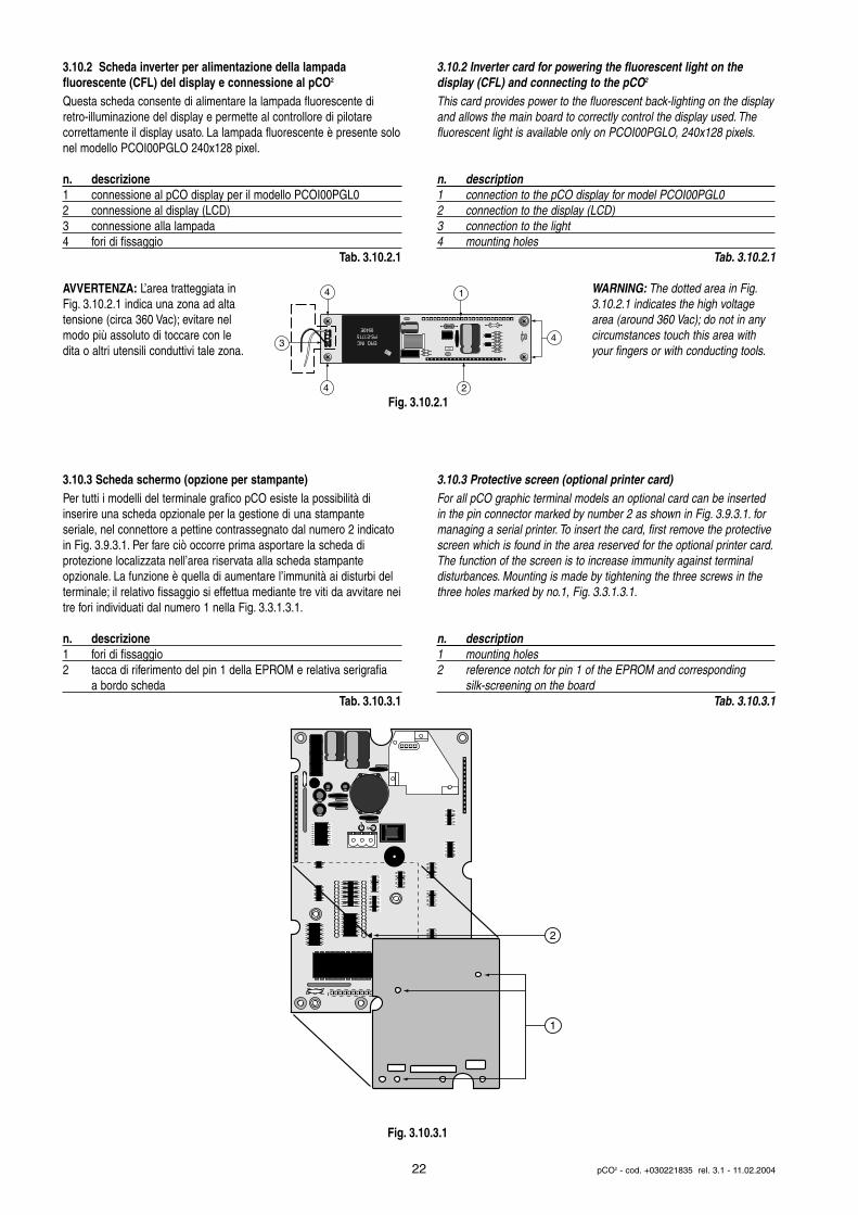
3.10.2 Scheda inverter per alimentazione della lampada fluorescente (CFL) del display e connessione al pCO2
Questa scheda consente di alimentare la lampada fluorescente diretro-illuminazione del display e permette al controllore di pilotare correttamente il display usato. La lampada fluorescente è presente solonel modello PCOI00PGLO 240x128 pixel.
n. descrizione1 connessione al pCO display per il modello PCOI00PGL02 connessione al display (LCD)3 connessione alla lampada4 fori di fissaggio
Tab. 3.10.2.1
AVVERTENZA: L’area tratteggiata inFig. 3.10.2.1 indica una zona ad altatensione (circa 360 Vac); evitare nelmodo più assoluto di toccare con ledita o altri utensili conduttivi tale zona.
3.10.3 Scheda schermo (opzione per stampante)Per tutti i modelli del terminale grafico pCO esiste la possibilità di inserire una scheda opzionale per la gestione di una stampante seriale, nel connettore a pettine contrassegnato dal numero 2 indicatoin Fig. 3.9.3.1. Per fare ciò occorre prima asportare la scheda di protezione localizzata nell’area riservata alla scheda stampante opzionale. La funzione è quella di aumentare l’immunità ai disturbi delterminale; il relativo fissaggio si effettua mediante tre viti da avvitare neitre fori individuati dal numero 1 nella Fig. 3.3.1.3.1.
n. descrizione1 fori di fissaggio2 tacca di riferimento del pin 1 della EPROM e relativa serigrafia
a bordo schedaTab. 3.10.3.1
3.10.2 Inverter card for powering the fluorescent light on thedisplay (CFL) and connecting to the pCO2
This card provides power to the fluorescent back-lighting on the displayand allows the main board to correctly control the display used. Thefluorescent light is available only on PCOI00PGLO, 240x128 pixels.
n. description1 connection to the pCO display for model PCOI00PGL02 connection to the display (LCD)3 connection to the light4 mounting holes
Tab. 3.10.2.1
WARNING: The dotted area in Fig.3.10.2.1 indicates the high voltagearea (around 360 Vac); do not in anycircumstances touch this area withyour fingers or with conducting tools.
3.10.3 Protective screen (optional printer card)For all pCO graphic terminal models an optional card can be insertedin the pin connector marked by number 2 as shown in Fig. 3.9.3.1. formanaging a serial printer. To insert the card, first remove the protectivescreen which is found in the area reserved for the optional printer card.The function of the screen is to increase immunity against terminaldisturbances. Mounting is made by tightening the three screws in thethree holes marked by no.1, Fig. 3.3.1.3.1.
n. description1 mounting holes2 reference notch for pin 1 of the EPROM and corresponding
silk-screening on the boardTab. 3.10.3.1
22 pCO2 - cod. +030221835 rel. 3.1 - 11.02.2004
F.1.
ERG INCPS-E1715
9549E
1nK400
RB59H3
3
2
1
4
4
4
1
2
Fig. 3.10.2.1
Fig. 3.10.3.1

4. INSTALLAZIONE
4.1 Ancoraggio del pCO2
Il pCO2 va installato su guida DIN. Per il fissaggio alla guida DIN, è sufficiente una leggera pressione del dispositivo preventivamenteappoggiato in corrispondenza della guida stessa. Lo scatto delle linguetteposteriori ne determina il bloccaggio alla guida. Lo smontaggio avvienealtrettanto semplicemente, curando di fare leva con un cacciavite, sulforo di sgancio delle linguette medesime per sollevarle. Le linguettesono tenute in posizione di blocco da molle di richiamo.
4.2 AlimentazioneIl pCO2 può essere alimentato a: 22…40 Vdc e 24 Vac ±15 %, 50/60 Hz.La potenza massima assorbita è Pmax= 15 W.Per l’alimentazione in corrente alternata, nell’installazione si deve utilizzare un trasformatore di sicurezza in Classe II, di almeno 50 VA econ 24 Vac in uscita. Ciò vale per l'alimentazione di un solo controllorepCO2. Se si prevede di alimentare più controllori pCO2 con il medesimotrasformatore, la potenza nominale di quest ultimo deve essere pari a nx 50 VA, dove n è il numero di controllori da alimentare dal trasformatore, indipendentemente dalla versione del controllore.Si raccomanda di separare l’alimentazione del controllore pCO2 e terminale (o più pCO2 e terminali) dall’alimentazione del resto deidispositivi elettrici (contattori di potenza ed altri componenti elettromeccanici), all’interno del quadro elettrico.
Qualora il secondario del trasformatore sia posto a terra, verificare cheil conduttore di terra deve essere collegato al morsetto G0. Se si alimentano più schede pCO2 collegate in rete pLAN, assicurarsi chesiano rispettati i riferimenti G e G0 (G0 dev’essere lo stesso per tutte leschede).
La tabella seguente riassume gli stati dei LED dell'alimentazione:
LED stato descrizionegiallo acceso/spento alimentazione attiva / non attivarosso acceso segnalazione overload di corrente su
alimentazione sonde (cortocircuito o anomalia)spento alimentazione sonde regolare
Tab. 4.2.1
4. INSTALLATION
4.1 Anchoring the pCO2
The pCO2 should be installed on a DIN rail. To fasten the unit to theDIN rail, lightly press it against the rail. The rear tabs will click intoplace, locking the unit to the rail. Removing the unit is just as simple,using a screwdriver through the release slot to lever and lift the tabs.The tabs are kept in the locked position by springs.
4.2 Power supply The pCO2 can be powered at: 22 to 40 Vdc and 24 Vac ±15 %, 50/60Hz. The maximum power consumed is Pmax= 15 W.For alternating current power supplies, during installation use a Class IIsafety transformer, rated to at least 50 VA and with a 24Vac output.This is valid for the power supply to just one pCO2 control.If you supply more pCO2 controller with the same transformer, its ratedvoltage must be n. x 50VA, where n. is the number of controllers to besupplied by the transformer, independently from the controller version.The power supply to the pCO2 control and the terminal (or to a seriesof pCO2 and terminals) must be separated from the power supply tothe other electrical devices (power contactors and other electromechanical components), inside the electrical panel.
If the transformer secondary is earthed, check that the ground wire isconnected to terminal G0. When powering a series of pCO2 boardsconnected in a pLAN network, check that the references G and G0 arerespected (G0 must be same for all the boards).
The following table summarises the states of the power LEDs.
LED status descriptionyellow ON/OFF power supply active / not activered ON probe power current overload signal
(short circuit or anomaly)OFF regular probe power
Tab. 4.2.1
23 pCO2 - cod. +030221835 rel. 3.1 - 11.02.2004
Fuse
built-in terminal
G G0
24 Vac/24 Vdc
LED gialloyellow LED LED rosso
red LED
Fig. 4.2.1
4.3 Avvertenze per l’installazione - ambienti di destinazione e collegamentoEvitare il montaggio delle schede negli ambienti che presentino leseguenti caratteristiche:• umidità relativa maggiore del 90%;• forti vibrazioni o urti;• esposizioni a continui getti d'acqua;• esposizione ad atmosfere aggressive ed inquinanti (es.: gas solforici
e ammoniacali, nebbie saline, fumi) con conseguente corrosione e/o ossidazione;
• elevate interferenze magnetiche e/o radiofrequenze (evitare quindi l'installazione delle macchine vicino ad antenne trasmittenti);
• esposizioni del pCO2 all'irraggiamento solare diretto e agli agenti atmosferici in genere;
• ampie e rapide fluttuazioni della temperatura ambiente;• ambienti ove sono presenti esplosivi o miscele di gas infiammabili;• esposizione alla polvere (formazione di patina corrosiva con possibile
ossidazione e riduzione dell'isolamento);
Per il collegamento è indispensabile seguire le seguenti avvertenze:• tensione di alimentazione elettrica diversa da quella prescritta può
danneggiare seriamente il sistema;• utilizzare capicorda adatti per i morsetti in uso. Allentare ciascuna vite
ed inserirvi i capicorda, quindi serrare le viti. Ad operazione ultimata tirare leggermente i cavi per verificarne il corretto serraggio;
• separare quanto più possibile i cavi dei segnali delle sonde e degli ingressi digitali dai cavi dei carichi induttivi e di potenza per evitare possibili disturbi elettromagnetici. Non inserire mai nelle stesse canaline (comprese quelle dei cavi elettrici) cavi di potenza e i cavi delle sonde. Evitare che i cavi delle sonde siano installati nelle immediate vicinanze di dispositivi di potenza (contattori, dispositivi magnetotermici o altro);
• ridurre il più possibile il percorso dei cavi dei sensori ed evitare che compiano percorsi a spirale che racchiudano dispositivi di potenza. Il collegamento delle sonde deve essere costituito da cavi schermati (sezione minima per ciascun conduttore: 0,5 mm2);
• evitare di avvicinarsi con le dita i componenti elettronici montati sulle schede per evitare scariche elettrostatiche (estremamente dannose) dall’operatore verso i componenti stessi;
• qualora il secondario del trasformatore di alimentazione sia posto a terra, verificare che lo stesso conduttore di terra corrisponda al conduttore che arriva al controllore ed entra nel morsetto G0;
• separare l’alimentazione delle uscite digitali dall’alimentazione del pCO2;
• non fissare i cavi ai morsetti premendo con eccessiva forza il cacciavite per evitare di danneggiare il pCO2.
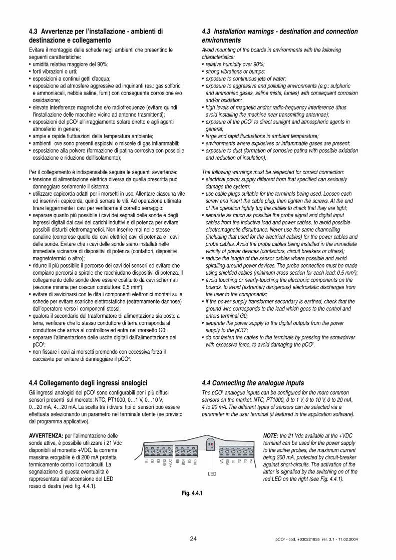
4.4 Collegamento degli ingressi analogiciGli ingressi analogici del pCO2 sono configurabili per i più diffusi sensori presenti sul mercato: NTC, PT1000, 0…1 V, 0…10 V, 0…20 mA, 4…20 mA. La scelta tra i diversi tipi di sensori può essereeffettuata selezionando un parametro nel terminale utente (se previstodal programma applicativo).
AVVERTENZA: per l’alimentazione dellesonde attive, è possibile utilizzare i 21 Vdcdisponibili al morsetto +VDC, la correntemassima erogabile è di 200 mA protetta termicamente contro i cortocircuiti. Lasegnalazione di questa eventualità è rappresentata dall'accensione del LEDrosso di destra (vedi fig. 4.4.1).
4.3 Installation warnings - destination and connectionenvironmentsAvoid mounting of the boards in environments with the following characteristics:• relative humidity over 90%;• strong vibrations or bumps;• exposure to continuous jets of water;• exposure to aggressive and polluting environments (e.g.: sulphuric
and ammoniac gases, saline mists, fumes) with consequent corrosionand/or oxidation;
• high levels of magnetic and/or radio-frequency interference (thus avoid installing the machine near transmitting antennae);
• exposure of the pCO2 to direct sunlight and atmospheric agents in general;
• large and rapid fluctuations in ambient temperature;• environments where explosives or inflammable gases are present;• exposure to dust (formation of corrosive patina with possible oxidation
and reduction of insulation);
The following warnings must be respected for correct connection:• electrical power supply different from that specified can seriously
damage the system;• use cable plugs suitable for the terminals being used. Loosen each
screw and insert the cable plug, then tighten the screws. At the end of the operation lightly tug the cables to check that they are tight;
• separate as much as possible the probe signal and digital input cables from the inductive load and power cables, to avoid possible electromagnetic disturbance. Never use the same channelling (including that used for the electrical cables) for the power cables andprobe cables. Avoid the probe cables being installed in the immediatevicinity of power devices (contactors, circuit breakers or others);
• reduce the length of the sensor cables where possible and avoid spiralling around power devices. The probe connection must be madeusing shielded cables (minimum cross-section for each lead: 0.5 mm2);
• avoid touching or nearly-touching the electronic components on the boards, to avoid (extremely dangerous) electrostatic discharges from the user to the components;
• if the power supply transformer secondary is earthed, check that the ground wire corresponds to the lead which goes to the control and enters terminal G0;
• separate the power supply to the digital outputs from the power supply to the pCO2;
• do not fasten the cables to the terminals by pressing the screwdriver with excessive force, to avoid damaging the pCO2.
4.4 Connecting the analogue inputsThe pCO2 analogue inputs can be configured for the more commonsensors on the market: NTC, PT1000, 0 to 1 V, 0 to 10 V, 0 to 20 mA, 4 to 20 mA. The different types of sensors can be selected via a parameter in the user terminal (if featured in the application software).
NOTE: the 21 Vdc available at the +VDCterminal can be used for the power supplyto the active probes, the maximum currentbeing 200 mA, protected by circuit-breakeragainst short-circuits. The activation of thelatter is signalled by the switching on of thered LED on the right (see Fig. 4.4.1).
24 pCO2 - cod. +030221835 rel. 3.1 - 11.02.2004
B1 B2 B3
GN
D
+VD
C B5
BC4 B5
BC5
VG VG0 Y1 Y2 Y3 Y4
LED
Fig. 4.4.1
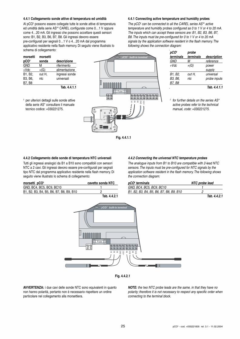
4.4.1 Collegamento sonde attive di temperatura ed umiditàAl pCO2 possono essere collegate tutte le sonde attive di temperaturaed umidità della serie AS*2 CAREL configurate come 0…1 V oppurecome 4…20 mA. Gli ingressi che possono accettare questi sensorisono: B1, B2, B3, B6, B7, B8. Gli ingressi devono essere pre-configurati per segnali 0…1 V o 4…20 mA dal programma applicativo residente nella flash memory. Di seguito viene illustrato loschema di collegamento:
morsetti morsettipCO2 sonda descrizioneGND M riferimento+Vdc +(G) alimentazioneB1, B2, out H, ingressi sondeB3, B6, ntc universaliB7, B8
Tab. 4.4.1.1
2 per ulteriori dettagli sulle sonde attive della serie AS* consultare il manuale tecnico codice: +030221275.
4.4.2 Collegamento delle sonde di temperatura NTC universaliTutti gli ingressi analogici da B1 a B10 sono compatibili con sensoriNTC a 2 cavi. Gli ingressi devono essere pre-configurati per segnalitipo NTC dal programma applicativo residente nella flash memory. Diseguito viene illustrato lo schema di collegamento:
morsetti pCO2 cavetto sonda NTCGND, BC4, BC5, BC9, BC10 1 B1, B2, B3, B4, B5, B6, B7, B8, B9, B10 2
Tab. 4.4.2.1
AVVERTENZA: i due cavi delle sonde NTC sono equivalenti in quantonon hanno polarità, pertanto non è necessario rispettare un ordine particolare nel collegamento alla morsettiera.
4.4.1 Connecting active temperature and humidity probesThe pCO2 can be connected to all the CAREL series AS*2 active temperature and humidity probes configured as 0 to 1 V or 4 to 20 mA.The inputs which can accept these sensors are: B1, B2, B3, B6, B7,B8. The inputs must be pre-configured for 0 to 1 V or 4 to 20 mAsignals by the application software resident in the flash memory. Thefollowing shows the connection diagram:
pCO2 probeterminals terminals descriptionGND M reference+Vdc +(G) power
supply B1, B2, out H, universalB3, B6, ntc probe inputsB7, B8
Tab. 4.4.1.1
2 for further details on the series AS* active probes refer to the technical manual, code: +030221275.
4.4.2 Connecting the universal NTC temperature probesThe analogue inputs from B1 to B10 are compatible with 2-lead NTCsensors. The inputs must be pre-configured for NTC signals by theapplication software resident in the flash memory. The following showsthe connection diagram:
pCO2 terminals NTC probe leadGND, BC4, BC5, BC9, BC10 1 B1, B2, B3, B4, B5, B6, B7, B8, B9, B10 2
Tab. 4.4.2.1
NOTE: the two NTC probe leads are the same, in that they have nopolarity; therefore it is not necessary to respect any specific order whenconnecting to the terminal block.
25 pCO2 - cod. +030221835 rel. 3.1 - 11.02.2004
Fuse
built-in terminal
B1 B2 B3
GN
D
+VD
C
out HMout T
+ (G)
Fuse
built-in terminal
B1 B2 B3
GN
D
+VD
C B4
BC4 B5
BC5
Fig. 4.4.1.1
Fig. 4.4.2.1
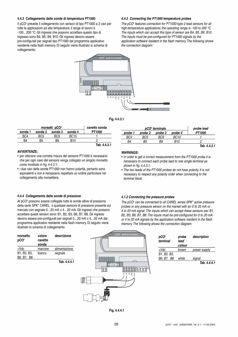
4.4.3 Collegamento delle sonde di temperatura PT1000Il pCO2 prevede il collegamento con sensori di tipo PT1000 a 2 cavi pertutte le applicazioni ad alta temperatura; il range di lavoro è -100…200 °C. Gli ingressi che possono accettare questo tipo di ingresso sono B4, B5, B9, B10. Gli ingressi devono essere pre-configurati per segnali tipo PT1000 dal programma applicativo residente nella flash memory. Di seguito viene illustrato lo schema dicollegamento:
morsetti pCO2 cavetto sondasonda 1 sonda 2 sonda 3 sonda 4 PT1000
BC4 BC5 BC9 BC10 1B4 B5 B9 B10 2
Tab. 4.4.3.1
AVVERTENZE:• per ottenere una corretta misura del sensore PT1000 è necessario
che per ogni cavo del sensore venga collegato un singolo morsetto come mostrato in fig. 4.4.3.1;
• i due cavi delle sonde PT1000 non hanno polarità, pertanto sono equivalenti e non è necessario rispettare un ordine particolare nel collegamento alla morsettiera.
4.4.4 Collegamento delle sonde di pressioneAl pCO2 possono essere collegate tutte le sonde attive di pressionedella serie SPK* CAREL o qualsiasi sensore di pressione presente sulmercato con segnale 0…20 mA o 4…20 mA. Gli ingressi che possonoaccettare questi sensori sono: B1, B2, B3, B6, B7, B8. Gli ingressidevono essere pre-configurati per segnali 0…20 mA o 4…20 mA dal programma applicativo residente nella flash memory. Di seguito vieneillustrato lo schema di collegamento:
morsetto colore descrizionepCO2 cavetto
sonda+Vdc marrone alimentazioneB1, B2, B3, bianco segnaleB6, B7, B8
Tab. 4.4.4.1
4.4.3 Connecting the PT1000 temperature probesThe pCO2 features connection for PT1000-type 2 lead sensors for allhigh-temperature applications; the operating range is -100 to 200 °C.The inputs which can accept this type of sensor are B4, B5, B9, B10.The inputs must be pre-configured for PT1000 signals by the application software resident in the flash memory. The following showsthe connection diagram:
pCO2 terminals probe lead probe 1 probe 2 probe 3 probe 4 PT1000
BC4 BC5 BC9 BC10 1B4 B5 B9 B10 2
Tab. 4.4.3.1
WARNINGS:• In order to get a correct measurement from the PT1000 probe it is
necessary to connect each probe lead to one single terminal as shown in fig. 4.4.3.1;
• The two leads of the PT1000 probes do not have polarity. It is not necessary to respect any polarity order when connecting to the terminal block.
4.1.2 Connecting the pressure probesThe pCO2 can be connected to all CAREL series SPK* active pressureprobes or any pressure sensor on the market with an 0 to 20 mA or 4 to 20 mA signal. The inputs which can accept these sensors are: B1,B2, B3, B6, B7, B8. The inputs must be pre-configured for 0 to 20 mAor 4 to 20 mA signals by the application software resident in the flashmemory. The following shows the connection diagram:
pCO2 probe descriptionterminal lead
colour+Vdc brown power supply B1, B2, B3, B6, B7, B8 white signal
Tab. 4.4.4.1
26 pCO2 - cod. +030221835 rel. 3.1 - 11.02.2004
Fuse
built-in terminal
B1 B2 B3
GN
D
+VD
C B4
BC4 B5
BC5
Fuse
built-in terminal
B1 B2 B3
GN
D
+VD
C
Fig. 4.4.3.1
Fig. 4.4.4.1
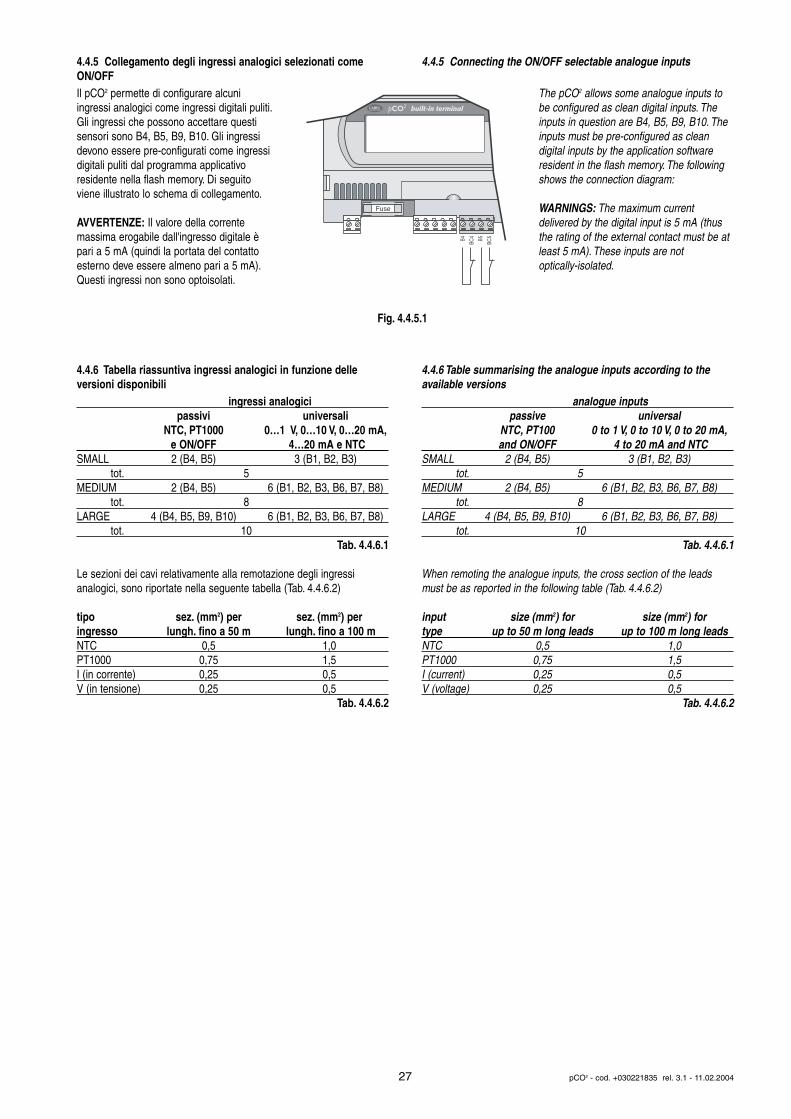
4.4.5 Collegamento degli ingressi analogici selezionati comeON/OFF Il pCO2 permette di configurare alcuniingressi analogici come ingressi digitali puliti.Gli ingressi che possono accettare questisensori sono B4, B5, B9, B10. Gli ingressidevono essere pre-configurati come ingressidigitali puliti dal programma applicativo residente nella flash memory. Di seguitoviene illustrato lo schema di collegamento.
AVVERTENZE: Il valore della corrente massima erogabile dall'ingresso digitale èpari a 5 mA (quindi la portata del contattoesterno deve essere almeno pari a 5 mA).Questi ingressi non sono optoisolati.
4.4.6 Tabella riassuntiva ingressi analogici in funzione delle versioni disponibili
ingressi analogicipassivi universali
NTC, PT1000 0…1 V, 0…10 V, 0…20 mA,e ON/OFF 4…20 mA e NTC
SMALL 2 (B4, B5) 3 (B1, B2, B3)tot. 5
MEDIUM 2 (B4, B5) 6 (B1, B2, B3, B6, B7, B8)tot. 8
LARGE 4 (B4, B5, B9, B10) 6 (B1, B2, B3, B6, B7, B8)tot. 10
Tab. 4.4.6.1
Le sezioni dei cavi relativamente alla remotazione degli ingressi analogici, sono riportate nella seguente tabella (Tab. 4.4.6.2)
tipo sez. (mm2) per sez. (mm2) peringresso lungh. fino a 50 m lungh. fino a 100 mNTC 0,5 1,0PT1000 0,75 1,5I (in corrente) 0,25 0,5V (in tensione) 0,25 0,5
Tab. 4.4.6.2
4.4.5 Connecting the ON/OFF selectable analogue inputs
The pCO2 allows some analogue inputs tobe configured as clean digital inputs. Theinputs in question are B4, B5, B9, B10. Theinputs must be pre-configured as clean digital inputs by the application softwareresident in the flash memory. The followingshows the connection diagram:
WARNINGS: The maximum current delivered by the digital input is 5 mA (thusthe rating of the external contact must be atleast 5 mA). These inputs are not optically-isolated.
4.4.6 Table summarising the analogue inputs according to theavailable versions
analogue inputspassive universal
NTC, PT100 0 to 1 V, 0 to 10 V, 0 to 20 mA,and ON/OFF 4 to 20 mA and NTC
SMALL 2 (B4, B5) 3 (B1, B2, B3)tot. 5
MEDIUM 2 (B4, B5) 6 (B1, B2, B3, B6, B7, B8)tot. 8
LARGE 4 (B4, B5, B9, B10) 6 (B1, B2, B3, B6, B7, B8)tot. 10
Tab. 4.4.6.1
When remoting the analogue inputs, the cross section of the leadsmust be as reported in the following table (Tab. 4.4.6.2)
input size (mm2) for size (mm2) fortype up to 50 m long leads up to 100 m long leadsNTC 0,5 1,0PT1000 0,75 1,5I (current) 0,25 0,5V (voltage) 0,25 0,5
Tab. 4.4.6.2
27 pCO2 - cod. +030221835 rel. 3.1 - 11.02.2004
Fuse
built-in terminal
B4
BC4 B5
BC5
Fig. 4.4.5.1
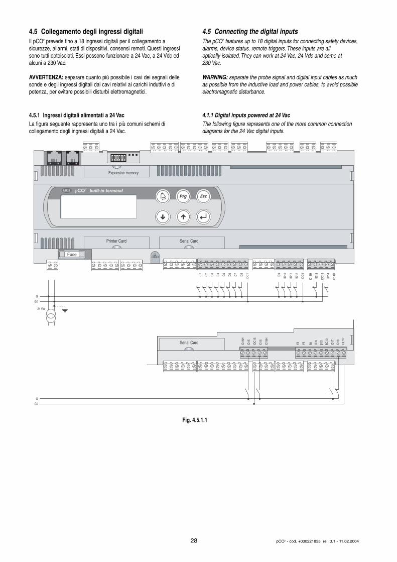
4.5 Collegamento degli ingressi digitaliIl pCO2 prevede fino a 18 ingressi digitali per il collegamento a sicurezze, allarmi, stati di dispositivi, consensi remoti. Questi ingressisono tutti optoisolati. Essi possono funzionare a 24 Vac, a 24 Vdc edalcuni a 230 Vac.
AVVERTENZA: separare quanto più possibile i cavi dei segnali dellesonde e degli ingressi digitali dai cavi relativi ai carichi induttivi e dipotenza, per evitare possibili disturbi elettromagnetici.
4.5.1 Ingressi digitali alimentati a 24 VacLa figura seguente rappresenta uno tra i più comuni schemi di collegamento degli ingressi digitali a 24 Vac.
4.5 Connecting the digital inputsThe pCO2 features up to 18 digital inputs for connecting safety devices,alarms, device status, remote triggers. These inputs are all optically-isolated. They can work at 24 Vac, 24 Vdc and some at 230 Vac.
WARNING: separate the probe signal and digital input cables as muchas possible from the inductive load and power cables, to avoid possibleelectromagnetic disturbance.
4.1.1 Digital inputs powered at 24 VacThe following figure represents one of the more common connectiondiagrams for the 24 Vac digital inputs.
28 pCO2 - cod. +030221835 rel. 3.1 - 11.02.2004
G
G0
24 Vac
G
G0
Fuse
Expansion memory
built-in terminal
ID1
ID2
ID3
ID4
ID5
ID6
ID7
ID8
IDC
1
ID9
ID10
ID11
ID12
IDC
9
ID13
H
ID13
IDC
13
ID14
ID14
H
Printer Card Serial CardID
15H
ID15
IDC
15
ID16
ID16
H
Y5 Y6 ID17
ID18
IDC
17
B9 BC9
B10
BC10
Serial Card
Fig. 4.5.1.1
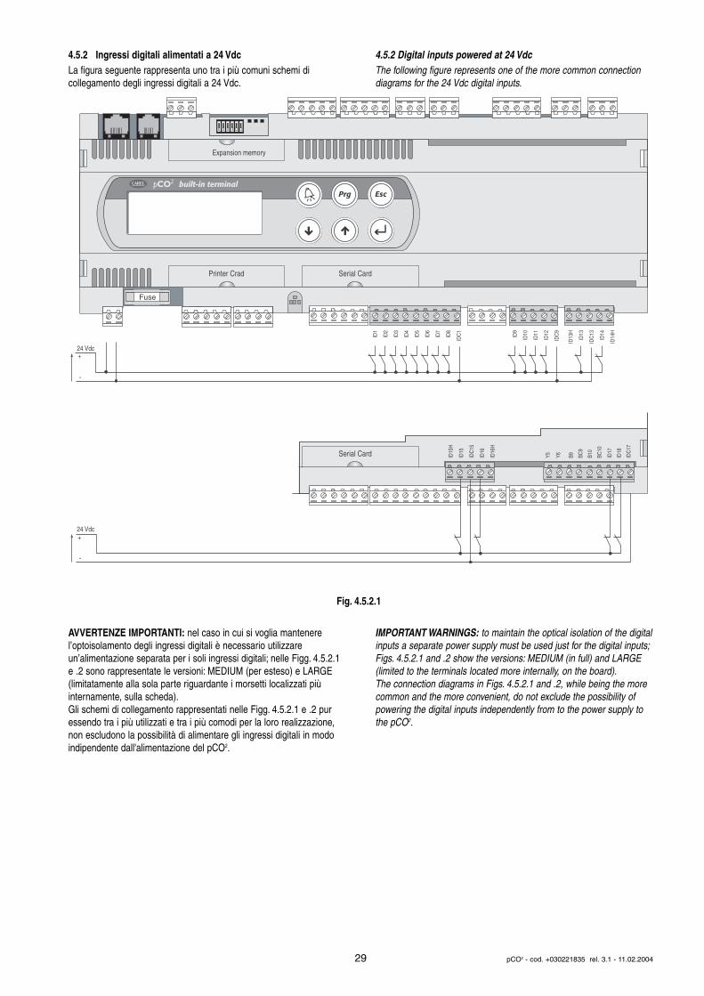
4.5.2 Ingressi digitali alimentati a 24 VdcLa figura seguente rappresenta uno tra i più comuni schemi di collegamento degli ingressi digitali a 24 Vdc.
AVVERTENZE IMPORTANTI: nel caso in cui si voglia mantenere l’optoisolamento degli ingressi digitali è necessario utilizzare un’alimentazione separata per i soli ingressi digitali; nelle Figg. 4.5.2.1e .2 sono rappresentate le versioni: MEDIUM (per esteso) e LARGE(limitatamente alla sola parte riguardante i morsetti localizzati più internamente, sulla scheda).Gli schemi di collegamento rappresentati nelle Figg. 4.5.2.1 e .2 puressendo tra i più utilizzati e tra i più comodi per la loro realizzazione,non escludono la possibilità di alimentare gli ingressi digitali in modoindipendente dall'alimentazione del pCO2.
4.5.2 Digital inputs powered at 24 VdcThe following figure represents one of the more common connectiondiagrams for the 24 Vdc digital inputs.
IMPORTANT WARNINGS: to maintain the optical isolation of the digitalinputs a separate power supply must be used just for the digital inputs;Figs. 4.5.2.1 and .2 show the versions: MEDIUM (in full) and LARGE(limited to the terminals located more internally, on the board).The connection diagrams in Figs. 4.5.2.1 and .2, while being the morecommon and the more convenient, do not exclude the possibility ofpowering the digital inputs independently from to the power supply tothe pCO2.
29 pCO2 - cod. +030221835 rel. 3.1 - 11.02.2004
Fuse
Expansion memory
built-in terminal
ID1
ID2
ID3
ID4
ID5
ID6
ID7
ID8
IDC
1
ID9
ID10
ID11
ID12
IDC
9
ID13
H
ID13
IDC
13
ID14
ID14
H
Printer Crad Serial Card
ID15
H
ID15
IDC
15
ID16
ID16
H
Y5 Y6 ID17
ID18
IDC
17
B9 BC9
B10
BC10
Serial Card
24 Vdc+
-
24 Vdc+
-
Fig. 4.5.2.1

4.5.3 Ingressi digitali alimentati a 230 VacLa figura seguente rappresenta uno tra i più comuni schemi di collegamento degli ingressi digitali a 230 Vac. Ogni gruppo (vediSignificato ingressi I/O) può essere sottoposto a tensioni diverse.All'interno di ogni gruppo non si può avere indipendenza degli ingressidigitali: per esempio, con riferimento alla Fig. 4.5.3.1 gli ingressi ID15 eID16, a causa del morsetto comune, devono essere alimentati allamedesima tensione per evitare pericolosi cortocircuiti e/o messe in tensione a 230 Vac di circuiti a tensione inferiore.
Il range di incertezza va da 43 a 90 Vac. È consigliato di usare un fusibile da 100 mA in serie agli ingressi digitali.
4.5.4 Tabella riassuntiva ingressi digitali in funzione delle versionidisponibili
n. ingr. optoisolati n. ingr. optoisolati totalea 24 Vac 50/60 Hz o a 24 Vac o ingressi
24 Vdc 230 Vac 50/60 HzSMALL 8 0 8MEDIUM 12 2 14LARGE 14 4 18
Tab. 4.5.4.1
AVVERTENZE IMPORTANTI: non collegare altri dispositivi agli ingressi IDN (ad esempio bobine di relè di rinvio del segnale ad altristrumenti). Nello specifico caso degli ingressi a 230 Vac è preferibileporre in parallelo alla bobina il filtro RC dedicato (le caratteristiche tipiche sono 100 W, 0,5 µF, 630 V); nella Fig. 4.2.1.3 è rappresentata lasola porzione di pCO2 riguardante i morsetti descritti. I modelliMEDIUM e LARGE sono del tutto simili.Se si collegano agli ingressi digitali dei sistemi di sicurezza (allarmi), sitenga presente quanto segue: la presenza di tensione agli estremidel contatto va considerata come condizione di normale funzionamento,mentre tensione assente (nulla) va considerata come situazione d'allarme. In tal modo viene assicurata anche la segnalazione di eventuale interruzione (o sconnessione) dell'ingresso.
Non collegare il neutro al posto di un ingresso digitale aperto.
Le sezioni dei cavi relativamente alla remotazione degli ingressi digitali,sono riportate nella seguente tabella (Tab. 4.5.4.2)
sez. (mm2) per lunghezze sez. (mm2) per lunghezzefino a 50 m fino a 100 m
0,25 0,5Tab. 4.5.4.2
4.5.3 Digital inputs powered at 230VacThe following figure represents one of the more common connectiondiagrams for the 230 Vac digital inputs. Each group (see Meaning ofI/O inputs) can have different voltages. Within each the digital inputsare not independent, however: for example, with reference to Fig.4.5.3.1, the inputs ID15 and ID16, due to the common terminal, mustbe powered at the same voltage to avoid dangerous short-circuitsand/or the powering of lower-voltage circuits at 230 Vac.
The range of uncertainty is from 43 to 90 Vac. It is recommended touse a 100 mA fuse in series with the digital inputs.
4.5.5 Table summarising the digital inputs according to the available versions
no. opto-isolated no. opto-isolated totalinputs at 24 Vac inputs a 24 Vac or inputs
50/60 Hz or 24 Vdc 230 Vac 50/60 HzSMALL 8 0 8MEDIUM 12 2 14LARGE 14 4 18
Tab. 4.5.4.1
IMPORTANT WARNINGS: do not connect other devices to the IDNinputs (for example, relay coils for sending signals to other instruments). In the specific case of the inputs at 230Vac, a dedicatedRC filter (typical characteristics: 100 W, 0.5 µF, 630 V) should be placedin parallel to the coil; Fig. 4.2.1.3 shows the part of the pCO2 involvingthe terminals described. The MEDIUM and LARGE models are verysimilar.If safety devices (alarms) are connected to the digital inputs, pleasekeep the following in mind: the presence of voltage at the ends of thecontact is a normal operating condition, while the absence of voltage isan alarm condition. In this way any interruption (or disconnection) ofthe input can be signalled.
Do not connect the neutral in the place of an open digital input.
When remoting the analogue inputs, the cross section of the leadsmust be as reported in the following table (Tab. 4.5.4.2)
size (mm2) for size (mm2) forup to 50 m long leads up to 100m long leads
0,25 0,5Tab. 4.5.4.2
30 pCO2 - cod. +030221835 rel. 3.1 - 11.02.2004
ID15
H
ID15
IDC
15
ID16
ID16
H
Y5 Y6 ID17
ID18
IDC
17
ID13
H
ID13
IDC
13
ID14
ID14
H
Serial Card
110/
230
Vac
+
-
Fig. 4.5.3.1
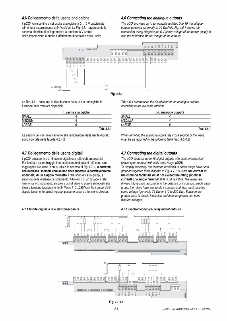
4.6 Collegamento delle uscite analogicheIl pCO2 fornisce fino a sei uscite analogiche a 0…10 V optoisolate alimentate esternamente a 24 Vac/Vdc. La Fig. 4.6.1 rappresenta loschema elettrico di collegamento; la tensione 0 V (zero) dell'alimentazione è anche il riferimento di tensione delle uscite.
La Tab. 4.6.1 riassume la distribuzione delle uscite analogiche in funzione delle versioni disponibili.
n. uscite analogicheSMALL 4MEDIUM 4LARGE 6
Tab. 4.6.1
Le sezioni dei cavi relativamente alla remotazione delle uscite digitali,sono riportate nella tabella 4.5.4.2
4.7 Collegamento delle uscite digitaliIl pCO2 prevede fino a 18 uscite digitali con relè elettromeccanici.Per facilità d'assemblaggio i morsetti comuni di alcuni relè sono statiraggruppati. Nel caso in cui si utilizzi lo schema di Fig. 4.7.1, la correnteche interessa i morsetti comuni non deve superare la portata (correntenominale) di un singolo morsetto. I relè sono divisi in gruppi, aseconda della distanza di isolamento. All’interno di un gruppo, i relèhanno tra loro isolamento singolo e quindi devono essere sottoposti allastessa tensione (generalmente 24 Vac o 110…230 Vac).Tra i gruppi c’è ildoppio isolamento quindi i gruppi possono essere a tensione diversa.
4.7.1 Uscite digitali a relè elettromeccanici
4.6 Connecting the analogue outputsThe pCO2 provides up to six optically-isolated 0 to 10 V analogue outputs powered externally at 24 Vac/Vdc. Fig. 4.6.1 shows the connection wiring diagram; the 0 V (zero) voltage of the power supply isalso the reference for the voltage of the outputs.
Tab. 4.6.1 summarises the distribution of the analogue outputs according to the available versions.
no. analogue outputsSMALL 4MEDIUM 4LARGE 6
Tab. 4.6.1
When remoting the analogue inputs, the cross section of the leadsmust be as reported in the following table (Tab. 4.5.4.2)
4.7 Connecting the digital outputsThe pCO2 features up to 18 digital outputs with electromechanicalrelays; upon request with solid state relays (SSR).To simplify assembly the common terminals of some relays have beengrouped together. If the diagram in Fig. 4.7.1 is used, the current atthe common terminals must not exceed the rating (nominal current) of a single terminal, that is 8A resistive. The relays are divided into groups, according to the distance of insulation. Inside eachgroup, the relays have just single insulation and thus must have thesame voltage (generally 24 Vac or 110 to 230 Vac). Between the groups there is double insulation and thus the groups can have different voltages.
4.7.1 Electromechanical relay digital outputs
31 pCO2 - cod. +030221835 rel. 3.1 - 11.02.2004
VG VG0 Y1 Y2 Y3 Y4
Y5 Y6 B9 BC9
B10
BC10
ID17
ID18
IDC
17
Serial Card
24 Vac/Vdc
Vout
Vout
Vout
Vout
Vout
Vout0 V
C1
NO
1
NO
2
NO
3
C1
C4
NO
4
NO
5
NO
6
C4
C7
NO
7
C7
NO
8
C8
NC
8
NO
12
C12
NC
12
NO
13
C13
NC
13
C9
NO
9
NO
10
NO
11
C9
N
L 110/
230-
24 V
ac
NO
14
C14
NC
14
NO
15
C15
NC
15
C16
NO
16
NO
17
NO
18
C16
N
L 110/
230-
24 V
ac
Fig. 4.6.1
Fig. 4.7.1.1
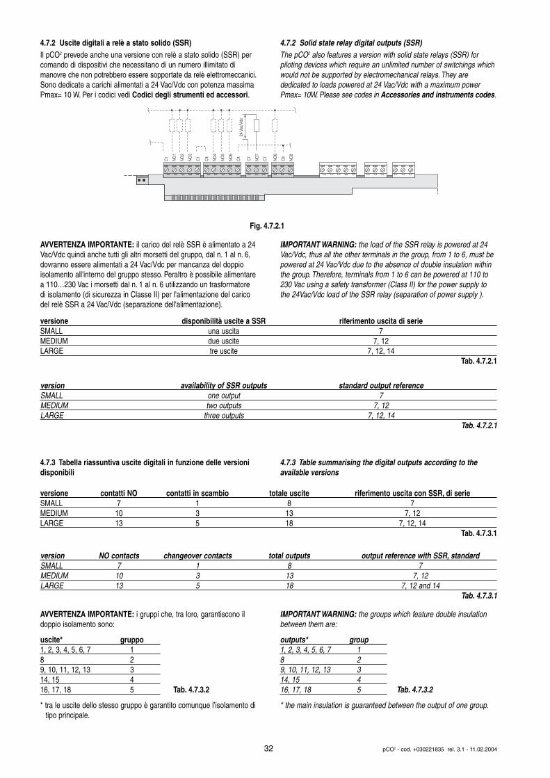
4.7.2 Uscite digitali a relè a stato solido (SSR) Il pCO2 prevede anche una versione con relè a stato solido (SSR) percomando di dispositivi che necessitano di un numero illimitato di manovre che non potrebbero essere sopportate da relè elettromeccanici.Sono dedicate a carichi alimentati a 24 Vac/Vdc con potenza massimaPmax= 10 W. Per i codici vedi Codici degli strumenti ed accessori.
AVVERTENZA IMPORTANTE: il carico del relè SSR è alimentato a 24Vac/Vdc quindi anche tutti gli altri morsetti del gruppo, dal n. 1 al n. 6,dovranno essere alimentati a 24 Vac/Vdc per mancanza del doppio isolamento all'interno del gruppo stesso. Peraltro è possibile alimentarea 110…230 Vac i morsetti dal n. 1 al n. 6 utilizzando un trasformatoredi isolamento (di sicurezza in Classe II) per l'alimentazione del caricodel relè SSR a 24 Vac/Vdc (separazione dell'alimentazione).
4.7.3 Tabella riassuntiva uscite digitali in funzione delle versionidisponibili
AVVERTENZA IMPORTANTE: i gruppi che, tra loro, garantiscono ildoppio isolamento sono:
uscite* gruppo1, 2, 3, 4, 5, 6, 7 18 29, 10, 11, 12, 13 314, 15 416, 17, 18 5 Tab. 4.7.3.2
* tra le uscite dello stesso gruppo è garantito comunque l’isolamento ditipo principale.
4.7.2 Solid state relay digital outputs (SSR)The pCO2 also features a version with solid state relays (SSR) for piloting devices which require an unlimited number of switchings whichwould not be supported by electromechanical relays. They are dedicated to loads powered at 24 Vac/Vdc with a maximum powerPmax= 10W. Please see codes in Accessories and instruments codes.
IMPORTANT WARNING: the load of the SSR relay is powered at 24Vac/Vdc, thus all the other terminals in the group, from 1 to 6, must bepowered at 24 Vac/Vdc due to the absence of double insulation withinthe group. Therefore, terminals from 1 to 6 can be powered at 110 to230 Vac using a safety transformer (Class II) for the power supply tothe 24Vac/Vdc load of the SSR relay (separation of power supply ).
4.7.3 Table summarising the digital outputs according to the available versions
IMPORTANT WARNING: the groups which feature double insulationbetween them are:
outputs* group1, 2, 3, 4, 5, 6, 7 18 29, 10, 11, 12, 13 314, 15 416, 17, 18 5 Tab. 4.7.3.2
* the main insulation is guaranteed between the output of one group.
32 pCO2 - cod. +030221835 rel. 3.1 - 11.02.2004
C1
NO
1
NO
2
NO
3
C1
C4
NO
4
NO
5
NO
6
C4
C7
NO
7
C7
NO
8
C8
NC
8
24 V
ac/V
dc
versione disponibilità uscite a SSR riferimento uscita di serieSMALL una uscita 7MEDIUM due uscite 7, 12LARGE tre uscite 7, 12, 14
Tab. 4.7.2.1
version availability of SSR outputs standard output reference SMALL one output 7MEDIUM two outputs 7, 12LARGE three outputs 7, 12, 14
Tab. 4.7.2.1
versione contatti NO contatti in scambio totale uscite riferimento uscita con SSR, di serieSMALL 7 1 8 7MEDIUM 10 3 13 7, 12LARGE 13 5 18 7, 12, 14
Tab. 4.7.3.1
version NO contacts changeover contacts total outputs output reference with SSR, standardSMALL 7 1 8 7MEDIUM 10 3 13 7, 12LARGE 13 5 18 7, 12 and 14
Tab. 4.7.3.1
Fig. 4.7.2.1
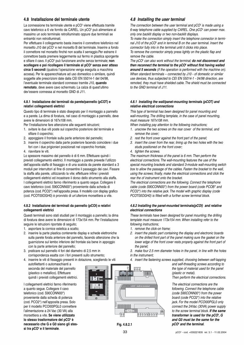
4.8 Installazione del terminale utenteLa connessione tra terminale utente e pCO2 viene effettuata tramitecavo telefonico a 6 vie fornito da CAREL. Un pCO2 può alimentare almassimo un solo terminale retroilluminato oppure due terminali seentrambi non retroilluminati.Per effettuare il collegamento basta inserire il connettore telefonico nelmorsetto J10 del pCO2 e nel morsetto B del terminale. Inserire a fondoil connettore nel morsetto finché non scatta il serraggio.Per estrarre ilconnettore basta premere leggermente sul fermo in plastica sporgentee sfilare il cavo. Il pCO2 può funzionare anche senza terminale; nonscollegare e poi ricollegare il terminale al pCO2 senza aver attesocirca 5 secondi (qualora l’operazione venga eseguita a macchinaaccesa). Per le apparecchiature ad uso domestico o similare, quindisoggette alle prescrizioni date dalla CEI EN 55014-1 del 04/98, l’eventuale terminale standard connesso tramite J10, quando remotato, deve avere cavo schermato. La calza di quest’ultimo dev’essere connessa al morsetto GND di J11.
4.8.1 Installazione dei terminali da parete/pannello (pCOT) e relativi collegamenti elettriciQuesto tipo di terminale è stato disegnato per il montaggio a pannelloe a parete. La dima di foratura, nel caso di montaggio a pannello, deveavere le dimensioni di 167x108 mm.Per l’installazione fare attenzione alle seguenti istruzioni;1. svitare le due viti poste sul coperchio posteriore del terminale e
sfilare il coperchio;2. appoggiare il frontale sulla parte anteriore del pannello;3. inserire il coperchio dalla parte posteriore facendo coincidere i due
fori con i due prigionieri posizionati nel coperchio frontale;4. riavvitare le viti.Lo spessore massimo del pannello è di 6 mm. Effettuare quindi i previsti collegamento elettrici. Il montaggio a parete prevede l’utilizzodell’apposita staffa di fissaggio e di una scatola da parete standard a 3moduli per interruttori al fine di consentire il passaggio dei cavi. Fissarela staffa alla parete, utilizzando la vite; effettuare infine i previsti collegamenti elettrici ed incastrare il dorso dello strumento alla staffa.I collegamenti elettrici fanno riferimento a quanto segue. Collegare ilcavo telefonico (cod. S90CONN00*) proveniente dalla scheda di potenza (cod. PCO2*) nell’apposita presa. Il modello con display grafico(cod. PCOT00OGH0) è provvisto di un’ulteriore morsettiera a vite.
4.8.2 Installazione dei terminali da pannello (pCOI) e relativi collegamenti elettriciQuesti terminali sono stati studiati per il montaggio a pannello; la dimadi foratura deve avere le dimensioni di 173x154 mm. Per l’installazioneseguire le istruzioni riportate di seguito;1. asportare la cornice estetica a scatto;2. inserire la parte plastica contenente display e schede elettroniche
sulla parete forata anteriore del pannello, facendo attenzione che laguarnizione sul lembo inferiore del frontale sia bene in appoggio con la parte anteriore del pannello;
3. praticare sul pannello 4 fori del diametro di 2,5 mm in corrispondenza esatta con i fori presenti sullo strumento;
4. inserire le viti di fissaggio presenti in dotazione, scegliendo le viti autofilettanti o automaschianti a seconda del materiale del pannello (plastico o metallico). Effettuare quindi i previsti collegamenti elettrici.
I collegamenti elettrici fanno riferimentoa quanto segue. Collegare il cavo telefonico (cod. S90CONN00*) proveniente dalla scheda di potenza(cod. PCO2*) nell’apposita presa. Soloper il modello PCOI00PGL0 connetterel’alimentazione a 24 Vac (30 VA) allamorsettiera a vite. Se viene utilizzatolo stesso trasformatore del pCO2 ènecessario che G e G0 siano gli stes-si tra pCO2 e il terminale.
4.8 Installing the user terminalThe connection between the user terminal and pCO2 is made using a6-way telephone cable supplied by CAREL. One pCO2 can power max.only one backlit display or two non-backlit displays.To make the connection simply insert the telephone connector in termi-nal J10 of the pCO2 and in terminal B on the user terminal. Insert theconnector fully into in the terminal until it clicks into place.To remove the connector simply press lightly on the plastic flap andremove the cable.The pCO2 can also work without the terminal; do not disconnect andthen reconnect the terminal to the pCO2 without first having waitedaround 5 seconds (if the operation is performed with the machine on).When standard terminals – connected by J10 - of domestic or similaruse devices, thus subjected to CEI EN 55014-1 - 04/98 direction, areremoted, they must have shielded cable. The shield must be connectedto the GND terminal of J11.
4.8.1 Installing the wall/panel-mounting terminals (pCOT) andrelative electrical connectionsThis type of terminal has been designed for panel mounting and wall-mounting. The drilling template, in the case of panel mounting,must measure 167x108 mm.When installing pay attention to the following instructions;1. unscrew the two screws on the rear cover of the terminal, and
remove the cover;2. rest the front cover against the front part of the panel;3. insert the cover from the rear, lining up the two holes with the two
studs positioned on the front cover;4. tighten the screws.The maximum thickness of the panel is 6 mm. Then perform the electrical connections. The wall-mounting features the use of the special mounting brackets and standard 3-module wall-mounting switchbox to allow the passage of the cables. Fasten the bracket to the wall,using the screws; finally, make the electrical connections and click therear the of instrument onto the bracket.The electrical connections are the following. Connect the telephonecable (code S90CONN00*) from the power board (code PCOB* andPCO2*) into the relative jack. The model with graphic display (codePCOT00OGH0) is fitted with a further screw terminal block.
4.8.2 Installing the panel-mounted terminals(pCOI) and relativeelectrical connectionsThese terminals have been designed for panel mounting; the drillingtemplate must measure 173x154 mm. When installing refer to the following instructions;1. remove the click-on frame;2. insert the plastic part containing the display and electronic boards
on the drilled front part of the panel making sure the gasket on the lower edge of the front cover rests properly against the front part of the panel;
3. make four 2.5 mm diameter holes in the panel, in line with the holesin the instrument;4. insert the fastening screws supplied, choosing between self-tapping
and self-threading screws according tothe type of material used for the panel(plastic or metal).Then perform the electrical connections.
The electrical connections are the following. Connect the telephone cable(code S90CONN00*) from the powerboard (code PCO2*) into the relativejack. For the model PCOI00PGL0 onlyconnect the 24Vac (30VA) power supplyto the screw terminal block. If the sametransformer is used for the pCO2, Gand G0 must be the same for thepCO2 and the terminal.
33 pCO2 - cod. +030221835 rel. 3.1 - 11.02.2004
Fuse
built-in terminal
AB
J10
Fig. 4.8.2.1
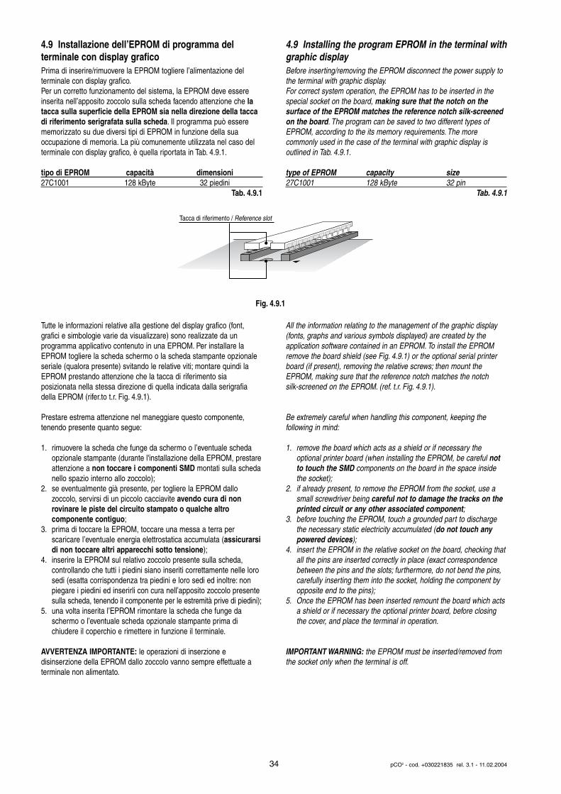
4.9 Installazione dell’EPROM di programma del terminale con display grafico Prima di inserire/rimuovere la EPROM togliere l’alimentazione del terminale con display grafico.Per un corretto funzionamento del sistema, la EPROM deve essereinserita nell’apposito zoccolo sulla scheda facendo attenzione che latacca sulla superficie della EPROM sia nella direzione della taccadi riferimento serigrafata sulla scheda. Il programma può esserememorizzato su due diversi tipi di EPROM in funzione della sua occupazione di memoria. La più comunemente utilizzata nel caso delterminale con display grafico, è quella riportata in Tab. 4.9.1.
tipo di EPROM capacità dimensioni27C1001 128 kByte 32 piedini
Tab. 4.9.1
Tutte le informazioni relative alla gestione del display grafico (font, grafici e simbologie varie da visualizzare) sono realizzate da un programma applicativo contenuto in una EPROM. Per installare laEPROM togliere la scheda schermo o la scheda stampante opzionaleseriale (qualora presente) svitando le relative viti; montare quindi laEPROM prestando attenzione che la tacca di riferimento sia posizionata nella stessa direzione di quella indicata dalla serigrafiadella EPROM (rifer.to t.r. Fig. 4.9.1).
Prestare estrema attenzione nel maneggiare questo componente,tenendo presente quanto segue:
1. rimuovere la scheda che funge da schermo o l’eventuale scheda opzionale stampante (durante l'installazione della EPROM, prestareattenzione a non toccare i componenti SMD montati sulla schedanello spazio interno allo zoccolo);
2. se eventualmente già presente, per togliere la EPROM dallo zoccolo, servirsi di un piccolo cacciavite avendo cura di non rovinare le piste del circuito stampato o qualche altro componente contiguo;
3. prima di toccare la EPROM, toccare una messa a terra per scaricare l’eventuale energia elettrostatica accumulata (assicurarsidi non toccare altri apparecchi sotto tensione);
4. inserire la EPROM sul relativo zoccolo presente sulla scheda, controllando che tutti i piedini siano inseriti correttamente nelle loro sedi (esatta corrispondenza tra piedini e loro sedi ed inoltre: non piegare i piedini ed inserirli con cura nell’apposito zoccolo presente sulla scheda, tenendo il componente per le estremità prive di piedini);
5. una volta inserita l’EPROM rimontare la scheda che funge da schermo o l’eventuale scheda opzionale stampante prima di chiudere il coperchio e rimettere in funzione il terminale.
AVVERTENZA IMPORTANTE: le operazioni di inserzione e disinserzione della EPROM dallo zoccolo vanno sempre effettuate aterminale non alimentato.
4.9 Installing the program EPROM in the terminal withgraphic display Before inserting/removing the EPROM disconnect the power supply tothe terminal with graphic display.For correct system operation, the EPROM has to be inserted in thespecial socket on the board, making sure that the notch on the surface of the EPROM matches the reference notch silk-screenedon the board. The program can be saved to two different types ofEPROM, according to the its memory requirements. The more commonly used in the case of the terminal with graphic display is outlined in Tab. 4.9.1.
type of EPROM capacity size27C1001 128 kByte 32 pin
Tab. 4.9.1
All the information relating to the management of the graphic display(fonts, graphs and various symbols displayed) are created by the application software contained in an EPROM. To install the EPROMremove the board shield (see Fig. 4.9.1) or the optional serial printerboard (if present), removing the relative screws; then mount theEPROM, making sure that the reference notch matches the notch silk-screened on the EPROM. (ref. t.r. Fig. 4.9.1).
Be extremely careful when handling this component, keeping the following in mind:
1. remove the board which acts as a shield or if necessary the optional printer board (when installing the EPROM, be careful not to touch the SMD components on the board in the space inside the socket);
2. if already present, to remove the EPROM from the socket, use a small screwdriver being careful not to damage the tracks on the printed circuit or any other associated component;
3. before touching the EPROM, touch a grounded part to discharge the necessary static electricity accumulated (do not touch any powered devices);
4. insert the EPROM in the relative socket on the board, checking thatall the pins are inserted correctly in place (exact correspondence between the pins and the slots; furthermore, do not bend the pins, carefully inserting them into the socket, holding the component by opposite end to the pins);
5. Once the EPROM has been inserted remount the board which acts a shield or if necessary the optional printer board, before closing the cover, and place the terminal in operation.
IMPORTANT WARNING: the EPROM must be inserted/removed fromthe socket only when the terminal is off.
34 pCO2 - cod. +030221835 rel. 3.1 - 11.02.2004
Tacca di riferimento / Reference slot
Fig. 4.9.1
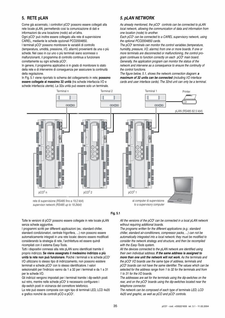
5. RETE pLANCome già accennato, i controllori pCO2 possono essere collegati allarete locale pLAN, permettendo così la comunicazione di dati e informazioni da una locazione (nodo) ad un’altra.Ogni pCO2 può inoltre essere collegato alla rete di supervisioneCAREL, mediante le schede opzionali PCO2004850.I terminali pCO2 possono monitorare le variabili di controllo (temperatura, umidità, pressione, I/O, allarmi) provenienti da una o piùschede. Nel caso in cui uno o più terminali siano sconnessi o malfunzionanti, il programma di controllo continua a funzionare correttamente su ogni scheda pCO2.In genere, il programma applicativo è in grado di monitorare lo statodella rete e di intervenire di conseguenza per assicurare la continuitàdella regolazione.In Fig. 5.1 viene riportato lo schema del collegamento in rete; possonoessere collegate al massimo 32 unità (tra schede interfaccia I/O eschede interfaccia utente). La 32a unità può essere solo un terminale.
Tutte le versioni di pCO2 possono essere collegate in rete locale pLANsenza schede aggiuntive.I programmi scritti per differenti applicazioni (es.: standard chiller, standard condizionatori, centrale frigorifera, ...) non possono essereautomaticamente integrati in una rete locale: devono essere modificaticonsiderando la strategia di rete, l’architettura ed essere quindi ricompilati con il sistema Easy-Tools.Tutti i dispositivi connessi alla rete pLAN sono identificati tramite il proprio indirizzo. Se viene assegnato il medesimo indirizzo a piùunità la rete non può funzionare. Poiché i terminali e le schede pCO2
I/O utilizzano lo stesso tipo di indirizzamento, non possono esistere terminali e schede pCO2 con lo stesso identificatore. I valori selezionabili per l'indirizzo vanno da 1 a 32 per i terminali e da 1 a 31per le schede I/O.Gli indirizzi vengono impostati per i terminali tramite i dip-switch postisul retro, mentre nelle schede pCO2 è necessario configurare i dip-switch posti in vicinanza del connettore telefonico.La rete può essere composta con ogni tipo di terminali LED, LCD 4x20e grafico nonché da controlli pCO e pCO2.
5. pLAN NETWORKAs already mentioned, the pCO2 controls can be connected to pLANlocal network, allowing the communication of data and information fromone location (node) to another.Each pCO2 can be connected to a CAREL supervisory network, usingthe optional PCO2004850 cards.The pCO2 terminals can monitor the control variables (temperature,humidity, pressure, I/O, alarms) from one or more boards. If one ormore terminals are disconnected or malfunctioning, the control pro-gram continues to function correctly on each pCO2 main board.Generally, the application program can monitor the status of thenetwork and intervene as a consequence to ensure the continuity ofthe control functions.The figure below, 5.1, shows the network connection diagram: a maximum of 32 units can be connected (including I/O interfacecards and user interface cards). The 32nd unit can only be a terminal.
All the versions of the pCO2 can be connected in a local pLAN networkwithout requiring additional boards.The programs written for the different applications (e.g.: standard chiller, standard air-conditioners, compressor packs, ...) can not beautomatically integrated into a local network: they must be modified toconsider the network strategy and structure, and then be recompiledwith the Easy-Tools system.All the devices connected to the pLAN network are identified usingtheir own individual address. If the same address is assigned tomore than one unit the network will not work. As the terminals andthe pCO2 I/O boards use the same type of address, terminals andpCO2 boards can not have the same identifier. The values which can beselected for the address range from 1 to 32 for the terminals and from1 to 31 for the I/O boards.The addresses are set for the terminals using the dip-switches on therear, and on the pCO2 boards using the dip-switches located near thetelephone connector.The network can be composed of each type of terminals LED, LCD4x20 and graphic, as well as pCO and pCO2 controls.
35 pCO2 - cod. +030221835 rel. 3.1 - 11.02.2004
on/off alarm enter
pCO2 n
Terminal n Printer
on/off alarm enter
pCO2 2
Terminal 2
on/off alarm enter
pCO2 1
Terminal 1
pLAN (RS485 62.5 kbit)
rete di supervisione (RS485 fino a 19,2 kbit)supervisor network (RS485 up to 19.2kbit)
al computer di supervisioneto a supervisory computer
Fuse
built-in terminal
Fuse
built-in terminal
Fuse
built-in terminal
Fig. 5.1
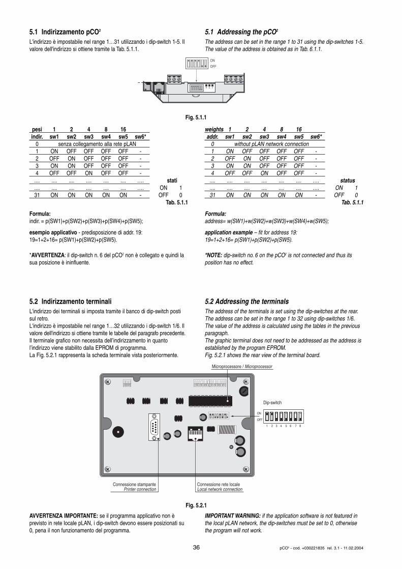
5.1 Indirizzamento pCO2
L'indirizzo è impostabile nel range 1…31 utilizzando i dip-switch 1-5. Ilvalore dell'indirizzo si ottiene tramite la Tab. 5.1.1.
pesi 1 2 4 8 16indir. sw1 sw2 sw3 sw4 sw5 sw6*
0 senza collegamento alla rete pLAN1 ON OFF OFF OFF OFF -2 OFF ON OFF OFF OFF -3 ON ON OFF OFF OFF -4 OFF OFF ON OFF OFF -.... .... .... .... .... .... …. stati.... .... .... .... .... .... …. ON 131 ON ON ON ON ON - OFF 0
Tab. 5.1.1
Formula:indir. = p(SW1)+p(SW2)+p(SW3)+p(SW4)+p(SW5);
esempio applicativo - predisposizione di addr. 19:19=1+2+16= p(SW1)+p(SW2)+p(SW5).
*AVVERTENZA: il dip-switch n. 6 del pCO2 non è collegato e quindi lasua posizione è ininfluente.
5.2 Indirizzamento terminaliL'indirizzo dei terminali si imposta tramite il banco di dip-switch postisul retro.L'indirizzo è impostabile nel range 1…32 utilizzando i dip-switch 1/6. Ilvalore dell'indirizzo si ottiene tramite le tabelle del paragrafo precedente.Il terminale grafico non necessita dell’indirizzamento in quanto l’indirizzo viene stabilito dalla EPROM di programma.La Fig. 5.2.1 rappresenta la scheda terminale vista posteriormente.
AVVERTENZA IMPORTANTE: se il programma applicativo non è previsto in rete locale pLAN, i dip-switch devono essere posizionati su0, pena il non funzionamento del programma.
5.1 Addressing the pCO2
The address can be set in the range 1 to 31 using the dip-switches 1-5.The value of the address is obtained as in Tab. 6.1.1.
weights 1 2 4 8 16addr. sw1 sw2 sw3 sw4 sw5 sw6*
0 without pLAN network connection1 ON OFF OFF OFF OFF -2 OFF ON OFF OFF OFF -3 ON ON OFF OFF OFF -4 OFF OFF ON OFF OFF -.... .... .... .... .... .... …. status.... .... .... .... .... .... …. ON 131 ON ON ON ON ON - OFF 0
Tab. 5.1.1
Formula:address= w(SW1)+w(SW2)+w(SW3)+w(SW4)+w(SW5);
application example – fit for address 19:19=1+2+16= p(SW1)+p(SW2)+p(SW5).
*NOTE: dip-switch no. 6 on the pCO2 is not connected and thus itsposition has no effect.
5.2 Addressing the terminalsThe address of the terminals is set using the dip-switches at the rear.The address can be set in the range 1 to 32 using dip-switches 1/6.The value of the address is calculated using the tables in the previous paragraph.The graphic terminal does not need to be addressed as the address isestablished by the program EPROM.Fig. 5.2.1 shows the rear view of the terminal board.
IMPORTANT WARNING: if the application software is not featured inthe local pLAN network, the dip-switches must be set to 0, otherwisethe program will not work.
36 pCO2 - cod. +030221835 rel. 3.1 - 11.02.2004
ON
OFF
R G V
1 2 3 4 5 6 7 8
ON OFF
Microprocessore / Microprocessor
Connessione stampante Printer connection
Connessione rete locale Local network connection
Dip-switch
Fig. 5.1.1
Fig. 5.2.1
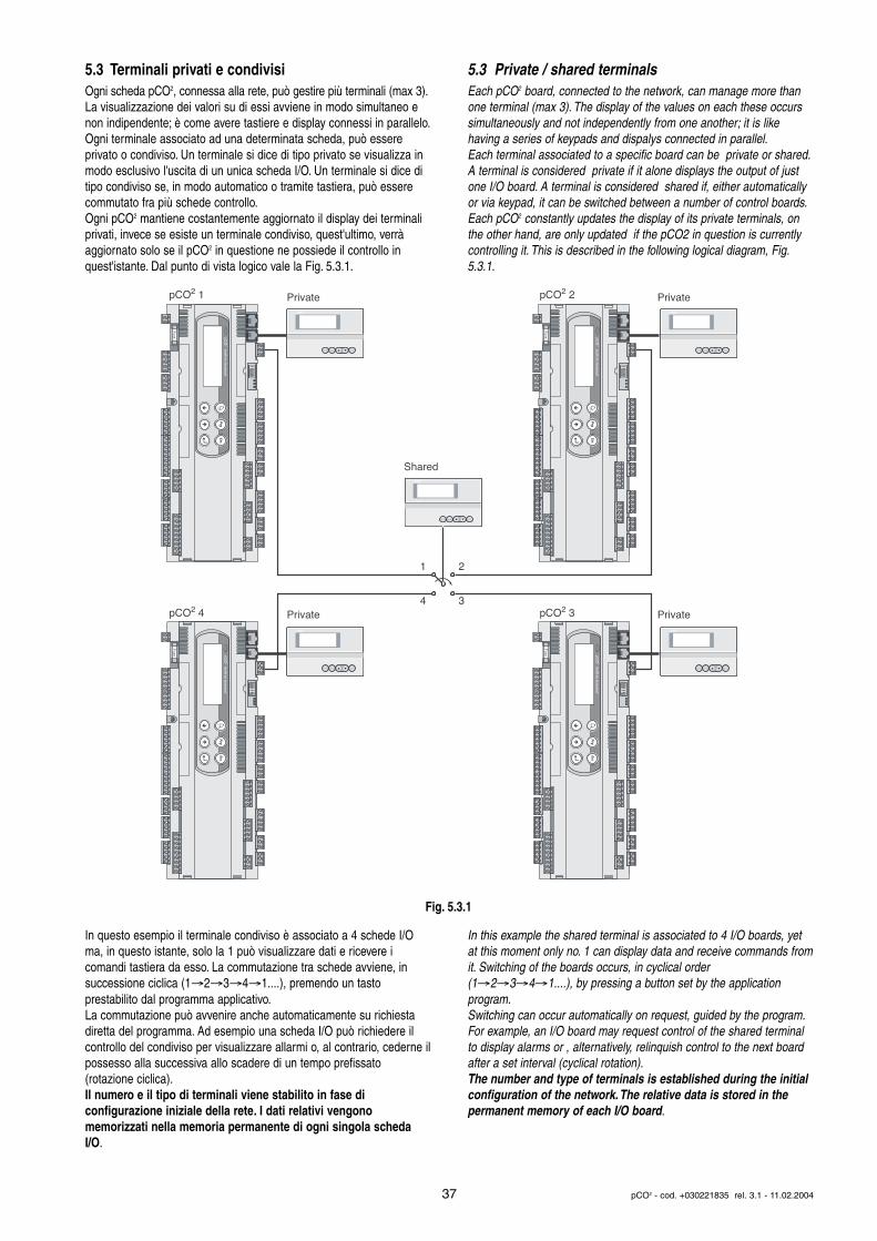
5.3 Terminali privati e condivisiOgni scheda pCO2, connessa alla rete, può gestire più terminali (max 3).La visualizzazione dei valori su di essi avviene in modo simultaneo enon indipendente; è come avere tastiere e display connessi in parallelo.Ogni terminale associato ad una determinata scheda, può essere privato o condiviso. Un terminale si dice di tipo privato se visualizza inmodo esclusivo l'uscita di un unica scheda I/O. Un terminale si dice ditipo condiviso se, in modo automatico o tramite tastiera, può esserecommutato fra più schede controllo.Ogni pCO2 mantiene costantemente aggiornato il display dei terminaliprivati, invece se esiste un terminale condiviso, quest'ultimo, verràaggiornato solo se il pCO2 in questione ne possiede il controllo in quest'istante. Dal punto di vista logico vale la Fig. 5.3.1.
In questo esempio il terminale condiviso è associato a 4 schede I/Oma, in questo istante, solo la 1 può visualizzare dati e ricevere icomandi tastiera da esso. La commutazione tra schede avviene, insuccessione ciclica (1→2→3→4→1....), premendo un tasto prestabilito dal programma applicativo.La commutazione può avvenire anche automaticamente su richiestadiretta del programma. Ad esempio una scheda I/O può richiedere ilcontrollo del condiviso per visualizzare allarmi o, al contrario, cederne ilpossesso alla successiva allo scadere di un tempo prefissato (rotazione ciclica).Il numero e il tipo di terminali viene stabilito in fase di configurazione iniziale della rete. I dati relativi vengono memorizzati nella memoria permanente di ogni singola schedaI/O.
5.3 Private / shared terminalsEach pCO2 board, connected to the network, can manage more thanone terminal (max 3). The display of the values on each these occurssimultaneously and not independently from one another; it is likehaving a series of keypads and dispalys connected in parallel.Each terminal associated to a specific board can be private or shared.A terminal is considered private if it alone displays the output of justone I/O board. A terminal is considered shared if, either automaticallyor via keypad, it can be switched between a number of control boards.Each pCO2 constantly updates the display of its private terminals, onthe other hand, are only updated if the pCO2 in question is currentlycontrolling it. This is described in the following logical diagram, Fig.5.3.1.
In this example the shared terminal is associated to 4 I/O boards, yetat this moment only no. 1 can display data and receive commands fromit. Switching of the boards occurs, in cyclical order(1→2→3→4→1....), by pressing a button set by the application program.Switching can occur automatically on request, guided by the program.For example, an I/O board may request control of the shared terminalto display alarms or , alternatively, relinquish control to the next boardafter a set interval (cyclical rotation).The number and type of terminals is established during the initialconfiguration of the network.The relative data is stored in the permanent memory of each I/O board.
37 pCO2 - cod. +030221835 rel. 3.1 - 11.02.2004
on/off alarm enter
on/off alarm enter
on/off alarm enter
on/off alarm enter on/off alarm enter
1 2
4 3pCO2 3 PrivatepCO2 4 Private
pCO2 2 PrivatepCO2 1 Private
Shared
Fuse
built-in terminal
Fuse
built-in terminal
Fuse
built-in terminal
Fuse
built-in terminal
Fig. 5.3.1
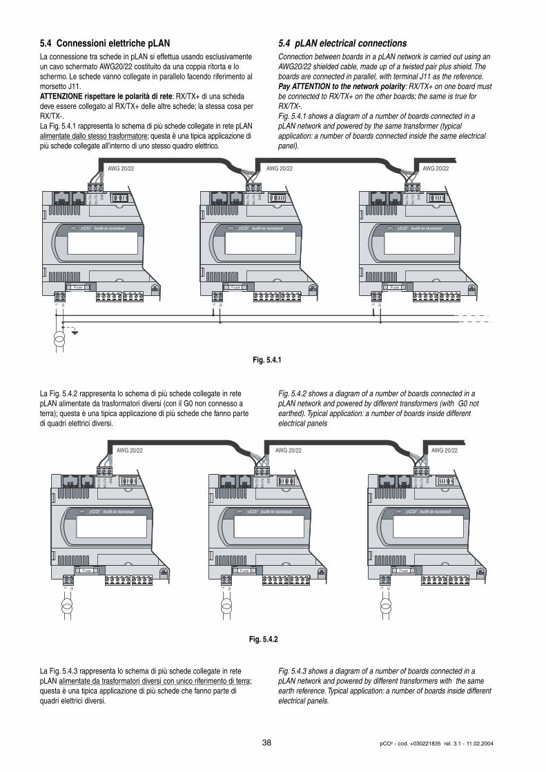
5.4 Connessioni elettriche pLANLa connessione tra schede in pLAN si effettua usando esclusivamenteun cavo schermato AWG20/22 costituito da una coppia ritorta e loschermo. Le schede vanno collegate in parallelo facendo riferimento almorsetto J11.ATTENZIONE rispettare le polarità di rete: RX/TX+ di una schedadeve essere collegato al RX/TX+ delle altre schede; la stessa cosa perRX/TX-.La Fig. 5.4.1 rappresenta lo schema di più schede collegate in rete pLANalimentate dallo stesso trasformatore; questa è una tipica applicazione dipiù schede collegate all’interno di uno stesso quadro elettrico.
La Fig. 5.4.2 rappresenta lo schema di più schede collegate in retepLAN alimentate da trasformatori diversi (con il G0 non connesso aterra); questa è una tipica applicazione di più schede che fanno partedi quadri elettrici diversi.
La Fig. 5.4.3 rappresenta lo schema di più schede collegate in retepLAN alimentate da trasformatori diversi con unico riferimento di terra;questa è una tipica applicazione di più schede che fanno parte di quadri elettrici diversi.
5.4 pLAN electrical connectionsConnection between boards in a pLAN network is carried out using anAWG20/22 shielded cable, made up of a twisted pair plus shield. Theboards are connected in parallel, with terminal J11 as the reference.Pay ATTENTION to the network polarity: RX/TX+ on one board mustbe connected to RX/TX+ on the other boards; the same is true forRX/TX-.Fig. 5.4.1 shows a diagram of a number of boards connected in apLAN network and powered by the same transformer (typical application: a number of boards connected inside the same electricalpanel).
Fig. 5.4.2 shows a diagram of a number of boards connected in apLAN network and powered by different transformers (with G0 notearthed). Typical application: a number of boards inside different electrical panels
Fig. 5.4.3 shows a diagram of a number of boards connected in apLAN network and powered by different transformers with the sameearth reference. Typical application: a number of boards inside differentelectrical panels.
38 pCO2 - cod. +030221835 rel. 3.1 - 11.02.2004
AWG 20/22 AWG 20/22 AWG 20/22
Fuse
built-in terminal
G G0
RX-
/TX+
RX+
/TX-
GN
D
Fuse
built-in terminal
G G0
RX-
/TX+
RX+
/TX-
GN
D
Fuse
built-in terminal
G G0
RX-
/TX+
RX+
/TX-
GN
D
AWG 20/22 AWG 20/22 AWG 20/22
Fuse
built-in terminal
G G0
RX-
/TX+
RX+
/TX-
GN
D
Fuse
built-in terminal
G G0
RX-
/TX+
RX+
/TX-
GN
D
Fuse
built-in terminal
G G0
RX-
/TX+
RX+
/TX-
GN
D
Fig. 5.4.1
Fig. 5.4.2
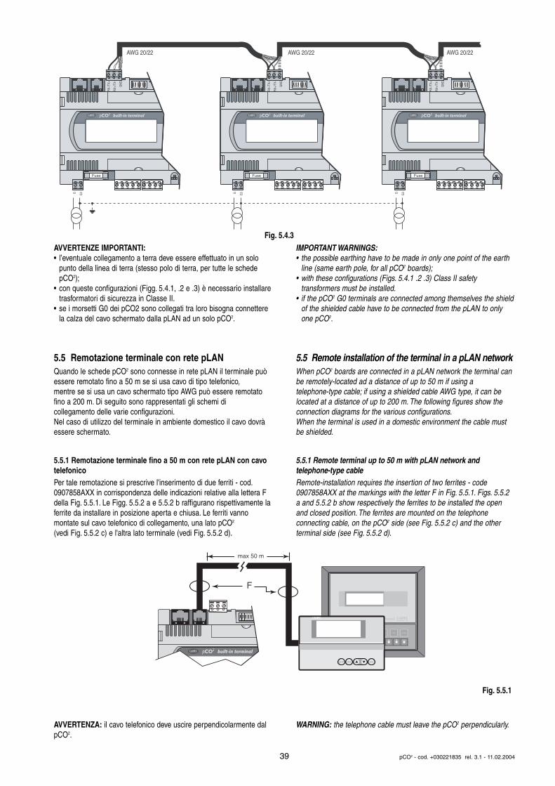
AVVERTENZE IMPORTANTI:• l’eventuale collegamento a terra deve essere effettuato in un solo
punto della linea di terra (stesso polo di terra, per tutte le schede pCO2);
• con queste configurazioni (Figg. 5.4.1, .2 e .3) è necessario installaretrasformatori di sicurezza in Classe II.
• se i morsetti G0 dei pCO2 sono collegati tra loro bisogna connettere la calza del cavo schermato dalla pLAN ad un solo pCO2.
5.5 Remotazione terminale con rete pLANQuando le schede pCO2 sono connesse in rete pLAN il terminale puòessere remotato fino a 50 m se si usa cavo di tipo telefonico, mentre se si usa un cavo schermato tipo AWG può essere remotatofino a 200 m. Di seguito sono rappresentati gli schemi di collegamento delle varie configurazioni.Nel caso di utilizzo del terminale in ambiente domestico il cavo dovràessere schermato.
5.5.1 Remotazione terminale fino a 50 m con rete pLAN con cavotelefonicoPer tale remotazione si prescrive l'inserimento di due ferriti - cod.0907858AXX in corrispondenza delle indicazioni relative alla lettera Fdella Fig. 5.5.1. Le Figg. 5.5.2 a e 5.5.2 b raffigurano rispettivamente laferrite da installare in posizione aperta e chiusa. Le ferriti vanno montate sul cavo telefonico di collegamento, una lato pCO2
(vedi Fig. 5.5.2 c) e l'altra lato terminale (vedi Fig. 5.5.2 d).
AVVERTENZA: il cavo telefonico deve uscire perpendicolarmente dalpCO2.
IMPORTANT WARNINGS:• the possible earthing have to be made in only one point of the earth
line (same earth pole, for all pCO2 boards);• with these configurations (Figs. 5.4.1 .2 .3) Class II safety
transformers must be installed.• if the pCO2 G0 terminals are connected among themselves the shield
of the shielded cable have to be connected from the pLAN to only one pCO2.
5.5 Remote installation of the terminal in a pLAN networkWhen pCO2 boards are connected in a pLAN network the terminal canbe remotely-located ad a distance of up to 50 m if using a telephone-type cable; if using a shielded cable AWG type, it can belocated at a distance of up to 200 m. The following figures show theconnection diagrams for the various configurations.When the terminal is used in a domestic environment the cable mustbe shielded.
5.5.1 Remote terminal up to 50 m with pLAN network and telephone-type cableRemote-installation requires the insertion of two ferrites - code0907858AXX at the markings with the letter F in Fig. 5.5.1. Figs. 5.5.2a and 5.5.2 b show respectively the ferrites to be installed the openand closed position. The ferrites are mounted on the telephone connecting cable, on the pCO2 side (see Fig. 5.5.2 c) and the other terminal side (see Fig. 5.5.2 d).
WARNING: the telephone cable must leave the pCO2 perpendicularly.
39 pCO2 - cod. +030221835 rel. 3.1 - 11.02.2004
AWG 20/22 AWG 20/22 AWG 20/22
Fuse
built-in terminal
G G0
RX-
/TX+
RX+
/TX-
GN
D
Fuse
built-in terminal
G G0
RX-
/TX+
RX+
/TX-
GN
D
Fuse
built-in terminal
G G0
RX-
/TX+
RX+
/TX-
GN
D
ve uscire perpendicolarmente dal
set prog.
enter
Terminal
on/off alarm enter
F
built-in terminal
max 50 m
Fig. 5.4.3
Fig. 5.5.1
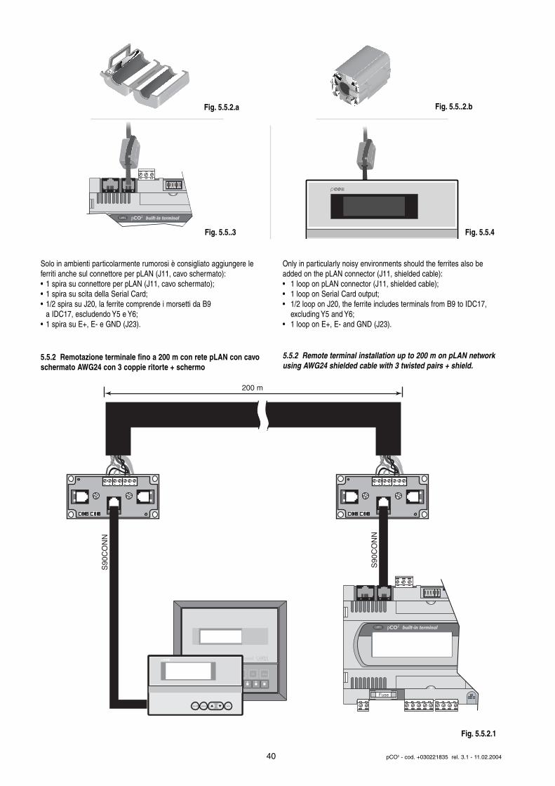
Solo in ambienti particolarmente rumorosi è consigliato aggiungere leferriti anche sul connettore per pLAN (J11, cavo schermato):• 1 spira su connettore per pLAN (J11, cavo schermato);• 1 spira su scita della Serial Card;• 1/2 spira su J20, la ferrite comprende i morsetti da B9
a IDC17, escludendo Y5 e Y6;• 1 spira su E+, E- e GND (J23).
5.5.2 Remotazione terminale fino a 200 m con rete pLAN con cavoschermato AWG24 con 3 coppie ritorte + schermo
Only in particularly noisy environments should the ferrites also beadded on the pLAN connector (J11, shielded cable):• 1 loop on pLAN connector (J11, shielded cable);• 1 loop on Serial Card output;• 1/2 loop on J20, the ferrite includes terminals from B9 to IDC17,
excluding Y5 and Y6;• 1 loop on E+, E- and GND (J23).
5.5.2 Remote terminal installation up to 200 m on pLAN networkusing AWG24 shielded cable with 3 twisted pairs + shield.
40 pCO2 - cod. +030221835 rel. 3.1 - 11.02.2004
Fuse
built-in terminal
set prog.
enter
Terminal
on/off alarm enter
200 m
S90
CO
NN
S90
CO
NN
Fig. 5.5.2.1
built-in terminal
COp
Fig. 5.5.2.a
Fig. 5.5..3 Fig. 5.5.4
Fig. 5.5..2.b
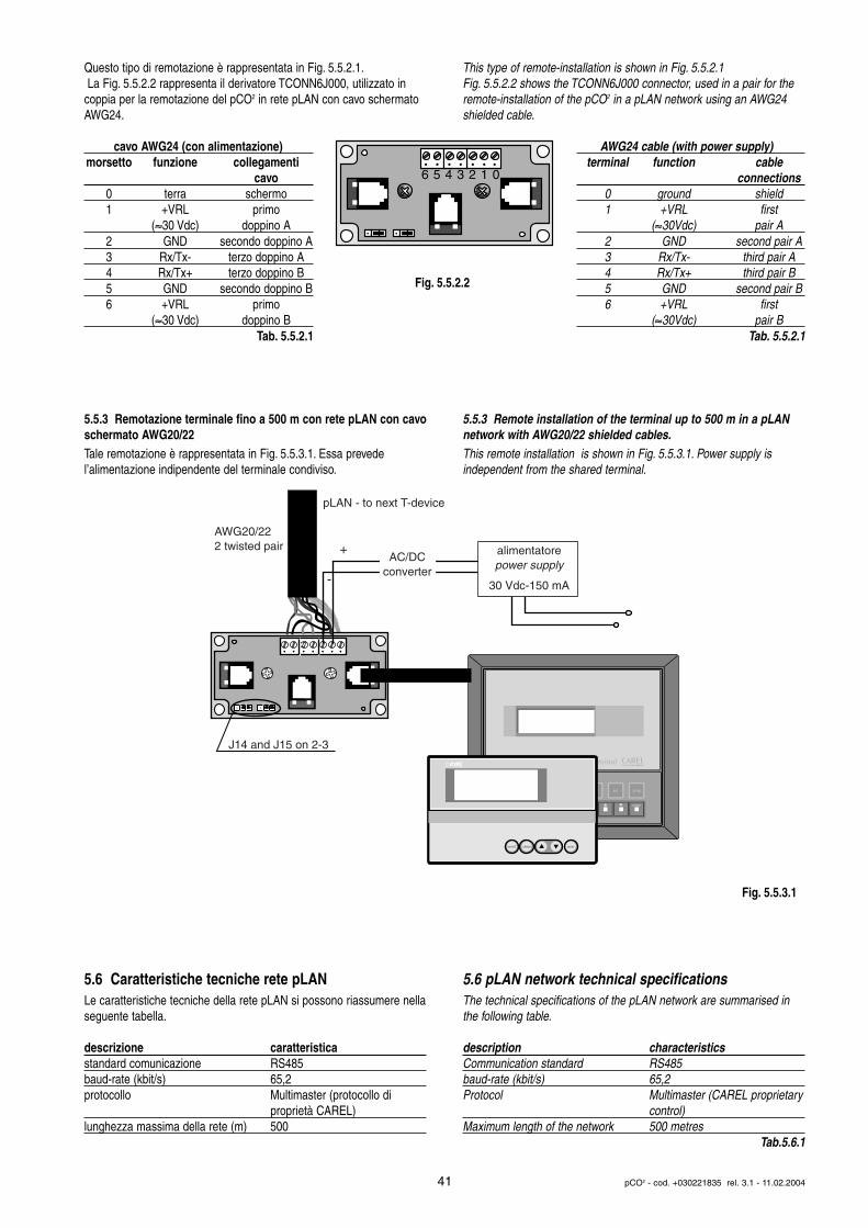
Questo tipo di remotazione è rappresentata in Fig. 5.5.2.1.La Fig. 5.5.2.2 rappresenta il derivatore TCONN6J000, utilizzato in
coppia per la remotazione del pCO2 in rete pLAN con cavo schermatoAWG24.
cavo AWG24 (con alimentazione)morsetto funzione collegamenti
cavo0 terra schermo1 +VRL primo
(≈30 Vdc) doppino A2 GND secondo doppino A3 Rx/Tx- terzo doppino A4 Rx/Tx+ terzo doppino B5 GND secondo doppino B6 +VRL primo
(≈30 Vdc) doppino BTab. 5.5.2.1
5.5.3 Remotazione terminale fino a 500 m con rete pLAN con cavoschermato AWG20/22 Tale remotazione è rappresentata in Fig. 5.5.3.1. Essa prevede l’alimentazione indipendente del terminale condiviso.
5.6 Caratteristiche tecniche rete pLANLe caratteristiche tecniche della rete pLAN si possono riassumere nellaseguente tabella.
descrizione caratteristicastandard comunicazione RS485baud-rate (kbit/s) 65,2protocollo Multimaster (protocollo di
proprietà CAREL)lunghezza massima della rete (m) 500
This type of remote-installation is shown in Fig. 5.5.2.1Fig. 5.5.2.2 shows the TCONN6J000 connector, used in a pair for theremote-installation of the pCO2 in a pLAN network using an AWG24shielded cable.
AWG24 cable (with power supply)terminal function cable
connections 0 ground shield1 +VRL first
(≈30Vdc) pair A2 GND second pair A3 Rx/Tx- third pair A4 Rx/Tx+ third pair B5 GND second pair B6 +VRL first
(≈30Vdc) pair BTab. 5.5.2.1
5.5.3 Remote installation of the terminal up to 500 m in a pLANnetwork with AWG20/22 shielded cables.This remote installation is shown in Fig. 5.5.3.1. Power supply is independent from the shared terminal.
5.6 pLAN network technical specifications The technical specifications of the pLAN network are summarised inthe following table.
description characteristicsCommunication standard RS485baud-rate (kbit/s) 65,2Protocol Multimaster (CAREL proprietary
control)Maximum length of the network 500 metres
Tab.5.6.1
41 pCO2 - cod. +030221835 rel. 3.1 - 11.02.2004
6 5 4 3 2 1 0
set prog.
enter
Terminal
on/off alarm enter
AC/DCconverter
J14 and J15 on 2-3
pLAN - to next T-device
AWG20/222 twisted pair +
-
alimentatorepower supply
30 Vdc-150 mA
Fig. 5.5.3.1
Fig. 5.5.2.2
6. SCHEDE OPZIONALI
6.1 Chiave di programmazione PCO201KEY0 ePCO202KEY0Le chiavi di programmazione PCO201KEY0 e PCO202KEY0 sonoun’opzione del controllore elettronico pCO2 che permettono di trasferireprogrammi da chiave a pCO2 e viceversa. È anche possibile effettuarecopie da WinLoad32 (software per PC per trasferimento programmi dae verso pCO2) verso la chiave.
PCO201KEY0: chiave con 1 MB di flash per pCO2 da usarsi con un pCO2 con 1+1 MB: PCO2xxxAxx o PCO2xxxBxx.
PCO202KEY0: chiave con 2 MB di flash per pCO2 da usarsi con un pCO2 con 2+2 MB: PCO2xxxCxx o PCO2xxxDxx.
Informazioni aggiuntive:• Nelle operazioni di copia da o verso la chiave, il software contenuto
nel destinatario viene interamente cancellato e sostituito con il software contenuto nel sorgente. Vengono copiati BOOT, BIOS, tabella BLK, tabella IUP e parametri tamponati. Quindi vengono copiati anche l’indirizzo pLAN ed eventuale PASSWORD di protezione del software. Non vengono copiati la taratura ed eventuali storici memorizzati su espansione di memoria.
• Le operazioni di copia da o verso la chiave sono indipendenti dal software contenuto nel destinatario. Mentre le operazioni di scarico con il WinLoad32 dipendono dal software presente nel destinatario.
• Ogni operazione di copia è possibile anche con indirizzo pLAN >0;per connettere il terminale locale con indirizzo a 0 o il WinLoad32 è sufficiente staccare il pCO2 della rete pLAN.
ATTENZIONE:• chiavi o pCO2 caricati con BOOT versione 3.xx DEVONO caricare
anche BIOS versione 3.xx e DEVONO comunicare SOLO con WinLoad32 versione 3.xx;
• se si esegue la copia da KEY verso pCO2, con KEY dotata di BOOT versione 3.xx e BIOS versione 3.xx e il pCO2 monta una flash da 1 MB, allora, terminata l’operazione di copia, BISOGNA scaricare nel pCO2 l’applicativo utilizzando WinLoad32 versione 3.xx.;
• se il pCO2 contiene il BOOT 2.xx gestisce solo 1 MB e BIOS inferiori al 3.20, se contiene il BOOT 3.xx gestisce sia 1 MB che i 2 MB e ottimizza lo spazio in memoria flash, inoltre, il BOOT 3.xx può essereutilizzato con qualsiasi BIOS;
• non caricare con Winload32 un BOOT inferiore al 2.05 su un pCO2 o chiave con 2 MB, se accade usare una chiave o il pCO2 per ristabilire una situazione funzionante.
AVVERTENZE IMPORTANTI: ogni movimentazione della chiave e delrelativo tasto di scambio devono essere effettuati a macchina spenta.Porre attenzione ai contatti elettrici durante il maneggio della chiavetta,onde evitare pericolose flessioni della basetta.
Nota: non utilizzare come “espansione di memoria” per gli storici altrimenti poi non è più utilizzabile come “chiave di programmazione”.
Per le caratteristiche tecniche e per le fasi di inserimento della schedadi espansione, seguire necessariamente le istruzioni riportate sul foglioistruzioni allegato alla confezione della scheda stessa (cod.+050003255).
6.2 Espansione di memoria: PCO200MEM0Se la memoria FLASH per il programma applicativo o gli storici non èsufficiente, il pCO2 permette di espandere la memoria con l’inserimentodi un scheda di espansione.
Per le caratteristiche tecniche e per le fasi di inserimento della schedadi espansione, seguire necessariamente le istruzioni riportate sul foglioistruzioni allegato alla confezione della scheda stessa (cod.+050003545).
6. OPTIONAL BOARDS
6.1 Programming key PCO201KEY0 and PCO202KEY0
The PCO201KEY0 and PCO202KEY0 are optional electronic cards ofpCO2 controller which allows you to transfer the programs from key topCO2 and vice versa. It possible also to make copies from WinLoad32(software for PC, for trasferring programs from and to pCO2) to key.
PCO201KEY0: 1MB flash key for pCO2 to be used with 1+1MB pCO2:PCO2xxxAxx or PCO2xxxBxx.
PCO202KEY0: 2MB flash key for pCO2 to be used with 2+2MB pCO2:PCO2xxxCxx or PCO2xxxDxx.
Additional information:• When copying from or to the key, the software contained in the target
is completely deleted and replaced with the software contained in thesource. The BOOT, BIOS, BLK table, IUP table and saved parametersare copied. The pLAN address and any software protection PASSWORDS are also copied. The calibration and any logs saved in the memory expansion are not copied.
• The copy from or to key operations are independent of the software loaded on the target, while the download operations using WinLoad32 depend on the software present in the target.
• All the copy operations can be performed with pLAN address >0; to connect the local terminal with address 0 or WinLoad32, simply remove the pCO2 from the pLAN network.
Warning:• keys or pCO2 loaded with BOOT version 3.xx MUST also be loaded
with BIOS version 3.xx and MUST communicate ONLY with WinLoad32 version 3.xx;
• if copying from the KEY to the pCO2, using a KEY with BOOT version3.xx and BIOS version 3.xx, and the pCO2 has a 1MB flash memory, then, once the copy operation has been completed, DOWNLOAD the application to pCO2 using WinLoad32 version 3.xx;
• if the pCO2 features the BOOT 2.xx it manages only 1MB and BIOS previous to the 3.20, if it features the BOOT 3.xx it manages both the 1MB and 2MB and optimise the the flash memory, moreover, the BOOT 3.xx can be used with every kind of BIOS;
• do not upload using Winload32 a BOOT previous to the 2.05 on a pCO2 or 2MB key, if it happens, use a key or the pCO2 to re-establish a normal operation.
IMPORTANT WARNINGS: all operations involving the key and the relative exchange button must be performed with the machine off. Payattention to the electrical contacts when handling the key, to avoid dangerous flexing of the terminal strip.
Note: do not use as “memory expansion” for the logs, otherwise it canno longer be used as “programming key”.
For details on the technical specifications and the installation of theexpansion board, refer to the instructions provided on the instructionsheet enclosed with the board itself (code +050003255).
6.1 Memory expansion: PCO200MEM0If the flash memory is not sufficient for the application software or datalogs, the pCO2 allows the memory to be expanded with the addition ofan expansion board.
For details on the technical specifications and the installation of theexpansion board, refer to the instructions provided on the instructionsheet enclosed with the board itself (code +050003545).
42 pCO2 - cod. +030221835 rel. 3.1 - 11.02.2004
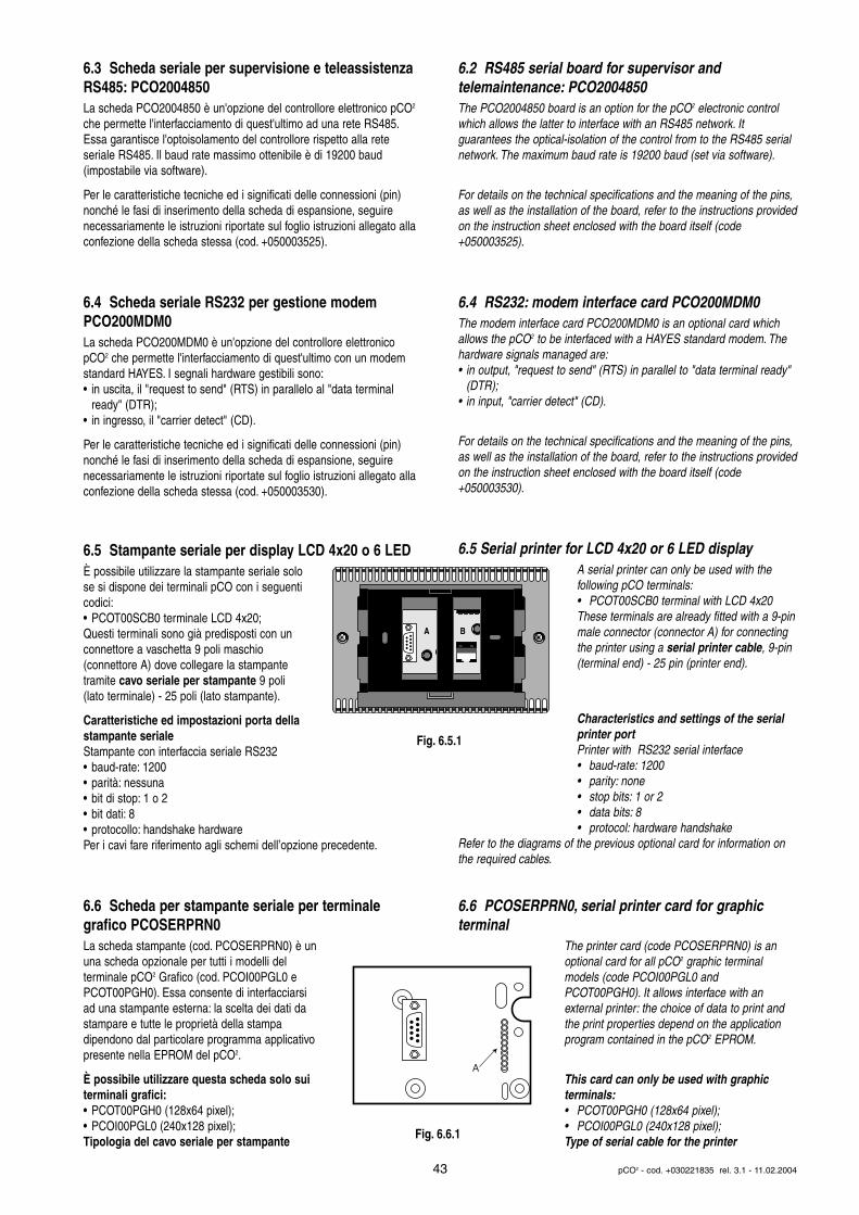
6.3 Scheda seriale per supervisione e teleassistenzaRS485: PCO2004850La scheda PCO2004850 è un'opzione del controllore elettronico pCO2
che permette l'interfacciamento di quest'ultimo ad una rete RS485.Essa garantisce l'optoisolamento del controllore rispetto alla rete seriale RS485. Il baud rate massimo ottenibile è di 19200 baud (impostabile via software).
Per le caratteristiche tecniche ed i significati delle connessioni (pin)nonché le fasi di inserimento della scheda di espansione, seguirenecessariamente le istruzioni riportate sul foglio istruzioni allegato allaconfezione della scheda stessa (cod. +050003525).
6.4 Scheda seriale RS232 per gestione modemPCO200MDM0La scheda PCO200MDM0 è un'opzione del controllore elettronicopCO2 che permette l'interfacciamento di quest'ultimo con un modemstandard HAYES. I segnali hardware gestibili sono:• in uscita, il "request to send" (RTS) in parallelo al "data terminal
ready" (DTR);• in ingresso, il "carrier detect" (CD).
Per le caratteristiche tecniche ed i significati delle connessioni (pin)nonché le fasi di inserimento della scheda di espansione, seguirenecessariamente le istruzioni riportate sul foglio istruzioni allegato allaconfezione della scheda stessa (cod. +050003530).
6.5 Stampante seriale per display LCD 4x20 o 6 LEDÈ possibile utilizzare la stampante seriale solose si dispone dei terminali pCO con i seguenticodici:• PCOT00SCB0 terminale LCD 4x20;Questi terminali sono già predisposti con unconnettore a vaschetta 9 poli maschio (connettore A) dove collegare la stampantetramite cavo seriale per stampante 9 poli(lato terminale) - 25 poli (lato stampante).
Caratteristiche ed impostazioni porta dellastampante serialeStampante con interfaccia seriale RS232• baud-rate: 1200• parità: nessuna• bit di stop: 1 o 2• bit dati: 8• protocollo: handshake hardwarePer i cavi fare riferimento agli schemi dell’opzione precedente.
6.6 Scheda per stampante seriale per terminale grafico PCOSERPRN0La scheda stampante (cod. PCOSERPRN0) è ununa scheda opzionale per tutti i modelli del terminale pCO2 Grafico (cod. PCOI00PGL0 ePCOT00PGH0). Essa consente di interfacciarsiad una stampante esterna: la scelta dei dati dastampare e tutte le proprietà della stampa dipendono dal particolare programma applicativopresente nella EPROM del pCO2.
È possibile utilizzare questa scheda solo sui terminali grafici:• PCOT00PGH0 (128x64 pixel);• PCOI00PGL0 (240x128 pixel);Tipologia del cavo seriale per stampante
6.2 RS485 serial board for supervisor and telemaintenance: PCO2004850The PCO2004850 board is an option for the pCO2 electronic controlwhich allows the latter to interface with an RS485 network. It guarantees the optical-isolation of the control from to the RS485 serialnetwork. The maximum baud rate is 19200 baud (set via software).
For details on the technical specifications and the meaning of the pins,as well as the installation of the board, refer to the instructions providedon the instruction sheet enclosed with the board itself (code+050003525).
6.4 RS232: modem interface card PCO200MDM0The modem interface card PCO200MDM0 is an optional card whichallows the pCO2 to be interfaced with a HAYES standard modem. Thehardware signals managed are:• in output, "request to send" (RTS) in parallel to "data terminal ready"
(DTR);• in input, "carrier detect" (CD).
For details on the technical specifications and the meaning of the pins,as well as the installation of the board, refer to the instructions providedon the instruction sheet enclosed with the board itself (code+050003530).
6.5 Serial printer for LCD 4x20 or 6 LED displayA serial printer can only be used with the following pCO terminals:• PCOT00SCB0 terminal with LCD 4x20These terminals are already fitted with a 9-pinmale connector (connector A) for connectingthe printer using a serial printer cable, 9-pin(terminal end) - 25 pin (printer end).
Characteristics and settings of the serial printer portPrinter with RS232 serial interface • baud-rate: 1200• parity: none• stop bits: 1 or 2• data bits: 8• protocol: hardware handshake
Refer to the diagrams of the previous optional card for information onthe required cables.
6.6 PCOSERPRN0, serial printer card for graphic terminal
The printer card (code PCOSERPRN0) is anoptional card for all pCO2 graphic terminalmodels (code PCOI00PGL0 andPCOT00PGH0). It allows interface with an external printer: the choice of data to print andthe print properties depend on the applicationprogram contained in the pCO2 EPROM.
This card can only be used with graphic terminals:• PCOT00PGH0 (128x64 pixel);• PCOI00PGL0 (240x128 pixel);Type of serial cable for the printer
43 pCO2 - cod. +030221835 rel. 3.1 - 11.02.2004
A B
A
Fig. 6.5.1
Fig. 6.6.1
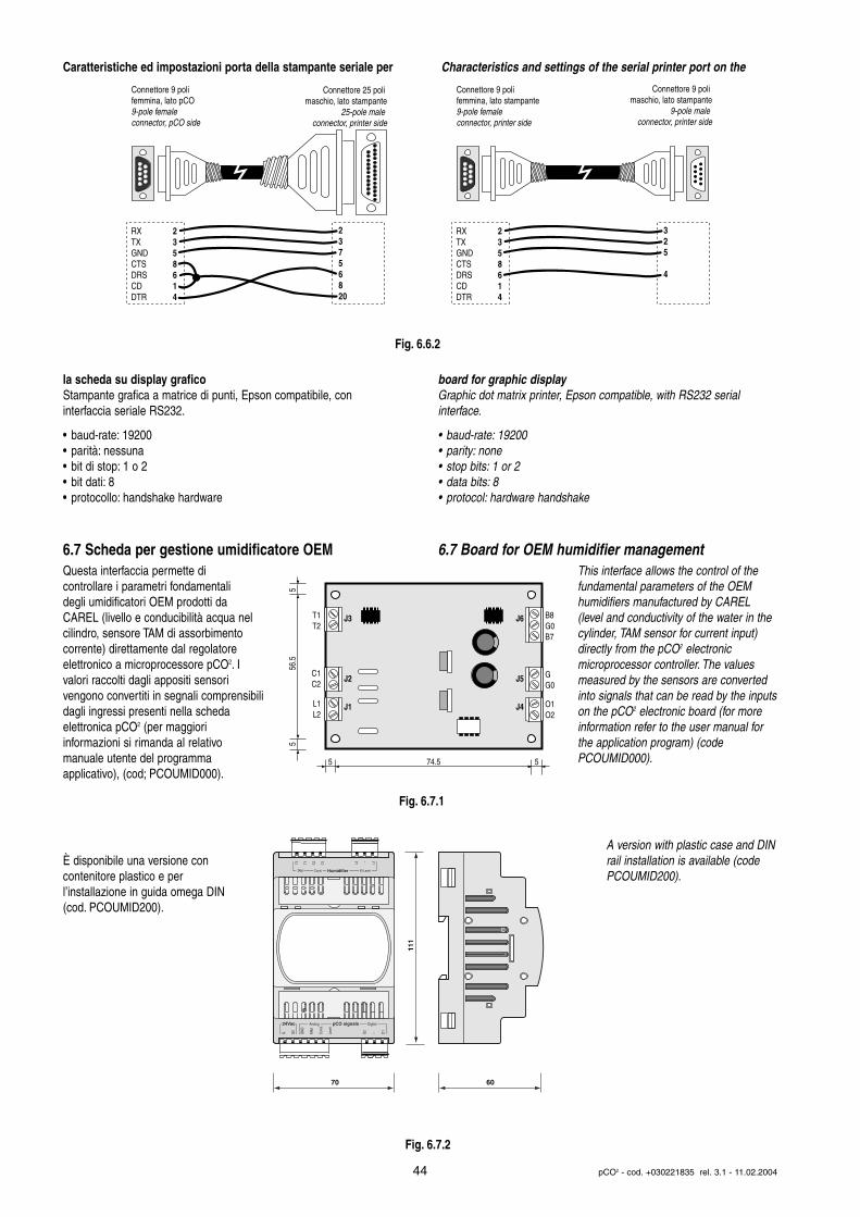
Caratteristiche ed impostazioni porta della stampante seriale per
la scheda su display graficoStampante grafica a matrice di punti, Epson compatibile, con interfaccia seriale RS232.
• baud-rate: 19200• parità: nessuna• bit di stop: 1 o 2• bit dati: 8• protocollo: handshake hardware
6.7 Scheda per gestione umidificatore OEMQuesta interfaccia permette di controllare i parametri fondamentali degli umidificatori OEM prodotti daCAREL (livello e conducibilità acqua nel cilindro, sensore TAM di assorbimento corrente) direttamente dal regolatore elettronico a microprocessore pCO2. Ivalori raccolti dagli appositi sensori vengono convertiti in segnali comprensibilidagli ingressi presenti nella scheda elettronica pCO2 (per maggiori informazioni si rimanda al relativo manuale utente del programma applicativo), (cod; PCOUMID000).
È disponibile una versione con contenitore plastico e per l’installazione in guida omega DIN (cod. PCOUMID200).
Characteristics and settings of the serial printer port on the
board for graphic displayGraphic dot matrix printer, Epson compatible, with RS232 serial interface.
• baud-rate: 19200• parity: none• stop bits: 1 or 2• data bits: 8• protocol: hardware handshake
6.7 Board for OEM humidifier managementThis interface allows the control of thefundamental parameters of the OEMhumidifiers manufactured by CAREL(level and conductivity of the water in the cylinder, TAM sensor for current input)directly from the pCO2 electronic microprocessor controller. The valuesmeasured by the sensors are convertedinto signals that can be read by the inputson the pCO2 electronic board (for moreinformation refer to the user manual forthe application program) (code PCOUMID000).
A version with plastic case and DINrail installation is available (codePCOUMID200).
44 pCO2 - cod. +030221835 rel. 3.1 - 11.02.2004
Connettore 9 poli femmina, lato pCO9-pole female connector, pCO side
Connettore 25 poli maschio, lato stampante
25-pole male connector, printer side
RX 2TX 3GND 5CTS 8DRS 6CD 1DTR 4
2 3 7 5 6 8 20
Connettore 9 poli femmina, lato stampante9-pole female connector, printer side
Connettore 9 poli maschio, lato stampante
9-pole male connector, printer side
RX 2TX 3GND 5CTS 8DRS 6CD 1DTR 4
3 2 5 4
J3
J2
J1
J6
J5
J4
B8G0B7
GG0
O1O2
T1T2
C1C2
L1L2
5 5 74.5
5 5
56.5
111
70 60
Fig. 6.6.2
Fig. 6.7.1
Fig. 6.7.2
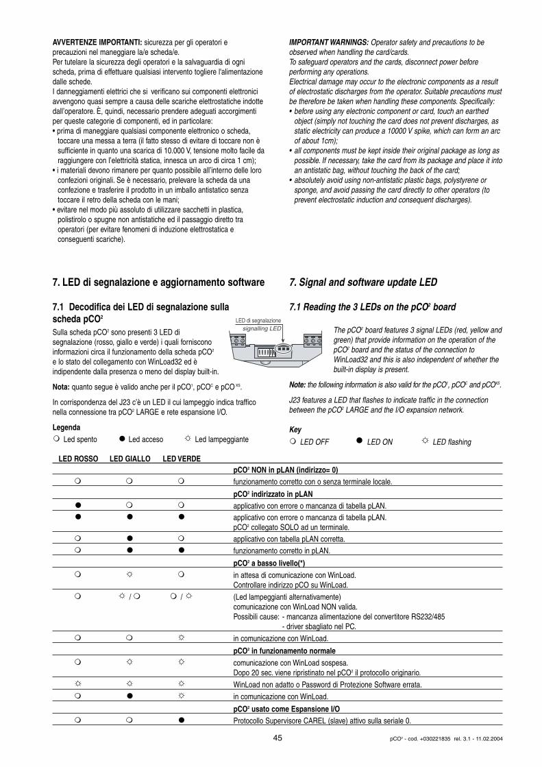
AVVERTENZE IMPORTANTI: sicurezza per gli operatori e precauzioni nel maneggiare la/e scheda/e.Per tutelare la sicurezza degli operatori e la salvaguardia di ogni scheda, prima di effettuare qualsiasi intervento togliere l'alimentazionedalle schede.I danneggiamenti elettrici che si verificano sui componenti elettroniciavvengono quasi sempre a causa delle scariche elettrostatiche indotte dall’operatore. È, quindi, necessario prendere adeguati accorgimentiper queste categorie di componenti, ed in particolare:• prima di maneggiare qualsiasi componente elettronico o scheda,
toccare una messa a terra (il fatto stesso di evitare di toccare non è sufficiente in quanto una scarica di 10.000 V, tensione molto facile daraggiungere con l’elettricità statica, innesca un arco di circa 1 cm);
• i materiali devono rimanere per quanto possibile all’interno delle loro confezioni originali. Se è necessario, prelevare la scheda da una confezione e trasferire il prodotto in un imballo antistatico senza toccare il retro della scheda con le mani;
• evitare nel modo più assoluto di utilizzare sacchetti in plastica, polistirolo o spugne non antistatiche ed il passaggio diretto tra operatori (per evitare fenomeni di induzione elettrostatica e conseguenti scariche).
7. LED di segnalazione e aggiornamento software
7.1 Decodifica dei LED di segnalazione sulla scheda pCO2
Sulla scheda pCO2 sono presenti 3 LED di segnalazione (rosso, giallo e verde) i quali fornisconoinformazioni circa il funzionamento della scheda pCO2
e lo stato del collegamento con WinLoad32 ed è indipendente dalla presenza o meno del display built-in.
Nota: quanto segue è valido anche per il pCO1, pCOC e pCO XS.
In corrispondenza del J23 c’è un LED il cui lampeggio indica trafficonella connessione tra pCO2 LARGE e rete espansione I/O.
LegendaLed spento Led acceso Led lampeggiante
IMPORTANT WARNINGS: Operator safety and precautions to beobserved when handling the card/cards.To safeguard operators and the cards, disconnect power before performing any operations.Electrical damage may occur to the electronic components as a resultof electrostatic discharges from the operator. Suitable precautions mustbe therefore be taken when handling these components. Specifically:• before using any electronic component or card, touch an earthed
object (simply not touching the card does not prevent discharges, as static electricity can produce a 10000 V spike, which can form an arc of about 1cm);
• all components must be kept inside their original package as long as possible. If necessary, take the card from its package and place it intoan antistatic bag, without touching the back of the card;
• absolutely avoid using non-antistatic plastic bags, polystyrene or sponge, and avoid passing the card directly to other operators (to prevent electrostatic induction and consequent discharges).
7. Signal and software update LED
7.1 Reading the 3 LEDs on the pCO2 board
The pCO2 board features 3 signal LEDs (red, yellow andgreen) that provide information on the operation of thepCO2 board and the status of the connection toWinLoad32 and this is also independent of whether thebuilt-in display is present.
Note: the following information is also valid for the pCO1, pCOC and pCOXS.
J23 features a LED that flashes to indicate traffic in the connectionbetween the pCO2 LARGE and the I/O expansion network.
Key
LED OFF LED ON LED flashing
45 pCO2 - cod. +030221835 rel. 3.1 - 11.02.2004
LED ROSSO LED GIALLO LED VERDEpCO2 NON in pLAN (indirizzo= 0)funzionamento corretto con o senza terminale locale.
pCO2 indirizzato in pLANapplicativo con errore o mancanza di tabella pLAN.applicativo con errore o mancanza di tabella pLAN.pCO2 collegato SOLO ad un terminale.applicativo con tabella pLAN corretta.funzionamento corretto in pLAN.
pCO2 a basso livello(*)in attesa di comunicazione con WinLoad.Controllare indirizzo pCO su WinLoad.
/ / (Led lampeggianti alternativamente)comunicazione con WinLoad NON valida.Possibili cause: - mancanza alimentazione del convertitore RS232/485
- driver sbagliato nel PC.
in comunicazione con WinLoad.
pCO2 in funzionamento normalecomunicazione con WinLoad sospesa.Dopo 20 sec. viene ripristinato nel pCO2 il protocollo originario.
WinLoad non adatto o Password di Protezione Software errata.
in comunicazione con WinLoad.
pCO2 usato come Espansione I/OProtocollo Supervisore CAREL (slave) attivo sulla seriale 0.
LED di segnalazionesignalling LED
*: casi in cui pCO2 regredisce allo stato Basso Livello:- In fase di avvio il pCO2 rileva la presenza del WinLoad collegato.- In fase di avvio il pCO2 rileva “Application corrupted…”.- Durante il normale funzionamento il pCO2 esegue un Atomo JUMP
mancante di reference corretta o all’indietro.Dopo 20 secondi di stato Basso Livello senza WinLoad collegato ilpCO2 si resetta automaticamente.
7.2 Avvio di un programma alternativo di debug presente nella key• Se il pCO2 viene avviato con la chiave inserita e il selettore della
chiave è in posizione Key (LED SELEZIONE rosso acceso ), senza premere i tasti del terminale locale, viene eseguito il programma residente nella chiave, senza modificare quello residente nel pCO2.In pratica, il controllore pCO2 può funzionare con un programma e/o Set-Up alternativo a quello residente.Questa funzione è utile per testare aggiornamenti di BIOS e/o APPLICATIVO, senza sovrascrivere il software residente nel pCO2.Risulta altresì molto utile per eseguire particolari funzioni o parti di programma (es. collaudo funzionale finale) utilizzando Set-Up parametri e/o speciale programma (espressamente sviluppato per queste funzioni) senza alterare il programma residente sul pCO2. Si utilizzano e modificano il programma e/o Set-Up parametri esclusivamente presenti nella chiave. Terminata questa fase, spento ilcontrollore pCO2, tolta la chiave, alla successiva riaccensione il pCO2
ritorna con il programma e Set-Up originali.• Se invece il selettore della chiave è in posizione pCO2 (LED
SELEZIONE verde acceso ) e non si premono i tasti del terminalelocale, la chiave non ha alcun effetto.
• È possibile verificare in qualsiasi momento la versione di programma in uso (tramite codice CRC espresso in esadecimale), e se questo è utilizzato dalla chiave o dal residente. Per verificare questo basterà procedere nel modo sotto indicato.
*: cases in which pCO2 reverts to Low Level status:- When starting the pCO2 detects that WinLoad is connected.- When starting the pCO2 detects “Application corrupted…”.- During normal operation the pCO2 runs a JUMP atom without the correct reference or backwards.
After 20 seconds of Low Level status without WinLoad connected, thepCO2 is automatically reset.
7.2 Starting an alternative debug program present inthe key• If the pCO2 is started with the key inserted and the key switch is set
to Key (red SELECTION LED ), and the buttons on the local terminal are not pressed, the program resident in the key is run, without modifying the program resident in the pCO2.In practice, the pCO2 controller can work using a software and/or Set-Up alternative to the resident one.This function is useful for testing BIOS and/or APPLICATION updates, without overwriting the software resident in the pCO2.Moreover, it is very useful for particular functions or software parts (ex. final operating test) using parameters Set-Up and/or special software (specifically developed for these functions) without alter the software resident on the pCO2. It is possible to use and modify only those software and/or Set-Up parameters housed in the key. Once this phase is complete, turn off the pCO2 controller, and removed the key, at the next start-up the pCO2 has the original software and Set-Up.
• If, on the other hand, the key switch is set to pCO2 (green
SELECTION LED ) and no buttons are pressed on the local terminal, the key has no effect.
• It is possible to check at any time the software version in use (through code CRC expressed in hexadecimal), and whether this is used by the key or resident. To check this, it is sufficient to proceed as follow.
46 pCO2 - cod. +030221835 rel. 3.1 - 11.02.2004
RED LED YELLOW LED GREEN LEDpCO2 NOT in pLAN (address= 0)correct operation with or without local terminal.
pCO2 pLAN address setapplication with error or no pLAN table.application with error or no pLAN table.pCO2 connected to ONLY one terminal.application with correct pLAN table.
correct operation in pLAN.
pCO2 at low level (*)awaiting communication with WinLoad.Check pCO address on WinLoad.
/ / (LED flashing alternately)communication with WinLoad NOT valid.Possible cause: - no power supply to the RS232/485 converter
- wrong driver on the PC.communicating with WinLoad.
pCO2 in normal operationcommunication with WinLoad on hold.After 20 sec. the original protocol is reset on the pCO2.WinLoad not suitable or incorrect Software Protection Password.communicating with WinLoad.
pCO2 used as I/O ExpansionCAREL supervisor protocol (slave) active on serial 0.
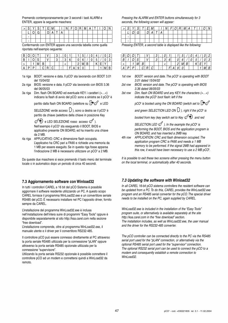
Premendo contemporaneamente per 3 secondi i tasti ALARM e ENTER, appare la seguente maschera:
> S Y S T E M I N F O R M A T I O NL O G D A T A--
Confermando con ENTER appare una seconda tabella come quellariportata nell’esempio seguente:
B O O T V 3 . 0 1 1 5 / 0 4 / 0 2B I O S V 3 . 3 6 0 6 / 0 5 / 0 3> 1 M B < 2 M B K E YA P P . C R C : F A 9 0 1 M B
1a riga BOOT: versione e data. Il pCO2 sta lavorando con BOOT 3.01del 15/04/02
2a riga BIOS: versione e data. Il pCO2 sta lavorando con BIOS 3.36 del 06/05/03
3a riga Dim. flash ON BOARD ed eventuale KEY. i caratteri (>…<) indicano la flash di avvio del pCO: sono a sinistra se il pCO2 è
partito dalla flash ON BOARD (selettore su e LED
SELEZIONE verde acceso ), sono a destra se il pCO2 è partito da chiave (selettore della chiave in posizione Key
e LED SELEZIONE rosso acceso ).Nell’esempio il pCO2 sta eseguendo il BOOT, BIOS e applicativo presente ON BOARD, ed ha inserito una chiave da 2 MB.
4a riga APPLICATIVO: CRC e dimensione flash occupata.L’applicatvo ha CRC pari a FA90 e richiede una memoria da 1 MB per essere eseguito. Se in questa riga fosse apparsa l’indicazione 2 MB è necessario utilizzare un pCO2 a 2 MB.
Da queste due maschere si esce premendo il tasto menù del terminalelocale o in automatico dopo un periodo di circa 40 secondi.
7.3 Aggiornamento software con Winload32In tutti i controllori CAREL a 16 bit del pCO Sistema è possibile aggiornare il software residente utilizzando un PC. A questo scopoCAREL fornisce il programma WinLoad32.exe e un convertitore serialeRS485 del pCO. È necessario installare nel PC l’apposito driver, fornitosempre da CAREL.
L’installazione del programma WinLoad32.exe è inclusa nell’installazione dell’intera suire di programmi “Easy Tools” oppure èdisponibile separatamente al sito http://ksa.carel.com nella sezione“free download”.L’installazione comprende, oltre al programma WinLoad32.exe, ilmanuale utente e il driver per il convertitore RS232-485.
Il controllore pCO può essere connesso direttamente al PC attraversola porta seriale RS485 utilizzata per la connessione “pLAN” oppureattraverso la porta seriale RS485 opzionale utilizzata per la connessione “supervisore”.Utilizando la porta seriale RS232 opzionale è possibile connettere ilcontrollore pCO ad un modem e connettersi quindi a WinLoad32 daremoto.
Pressing the ALARM and ENTER buttons simultaneously for 3seconds, the following screen will appear:
> S Y S T E M I N F O R M A T I O NL O G D A T A--
Pressing ENTER, a second table is displayed like the following:
B O O T V 3 . 0 1 1 5 / 0 4 / 0 2B I O S V 3 . 3 6 0 6 / 0 5 / 0 3> 1 M B < 2 M B K E YA P P . C R C : F A 9 0 1 M B
1st row BOOT: version and date. The pCO2 is operating with BOOT 3.01 dated 15/04/02
2st row BIOS: version and date. The pCO2 is operating with BIOS 3.36 dated 06/05/03
3st row Dim. flash ON BOARD and any KEY. the characters (>…<) indicate the pCO2 boot flash: left if the
pCO2 is booted using the ON BOARD (switch set to
and green SELECTION LED ON ), right if the pCO2 is
booted from key (key switch set to Key and red
SELECTION LED ). In the example the pCO2 is performing the BOOT, BIOS and the application program is ON BOARD, and has inserted a 2MB key.
4th row APPLICATION: CRC and flash dimension occupied. The application program CRC is FA90 and needs a 1 MB memory to be performed. If the signal 2MB had appeared in this row, it would have been necessary to use a 2 MB pCO2.
It is possible to exit these two screens either pressing the menu buttonon the local terminal, or automatically after 40 seconds.
7.3 Updating the software with Winload32In all CAREL 16-bit pCO sistema controllers the resident software canbe updated from a PC. To do this, CAREL provides the WinLoad32.exeprogram and an RS485 serial converter for the pCO. The special driverneeds to be installed on the PC, again supplied by CAREL.
WinLoad32.exe is included in the installation of the “Easy Tools”program suite, or alternatively is available separately at the sitehttp://ksa.carel.com in the “free download” section.The installation includes, as well as WinLoad32.exe, the user manualand the driver for the RS232-485 converter.
The pCO controller can be connected directly to the PC via the RS485serial port used for the “pLAN” connection, or alternatively via theoptional RS485 serial port used for the “supervisor” connection.The optional RS232 serial port can be used to connect the pCO to amodem and consequently establish a remote connection toWinLoad32.
47 pCO2 - cod. +030221835 rel. 3.1 - 11.02.2004
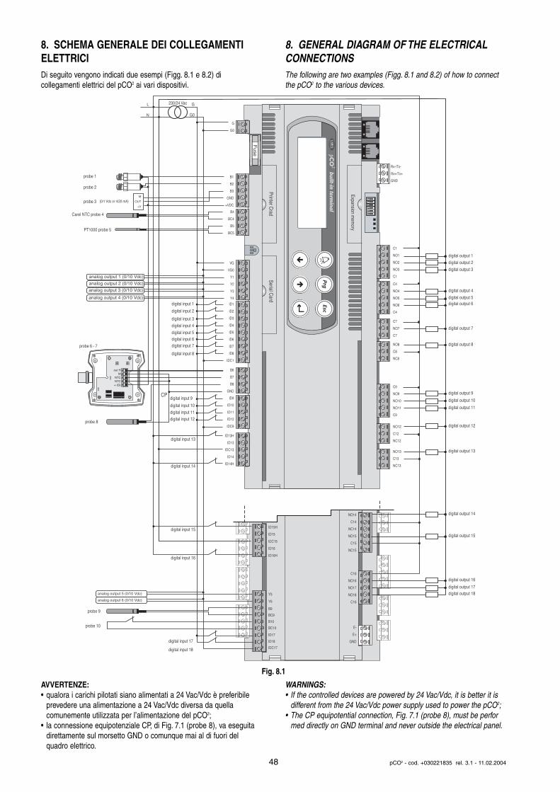
8. SCHEMA GENERALE DEI COLLEGAMENTIELETTRICIDi seguito vengono indicati due esempi (Figg. 8.1 e 8.2) di collegamenti elettrici del pCO2 ai vari dispositivi.
AVVERTENZE:• qualora i carichi pilotati siano alimentati a 24 Vac/Vdc è preferibile
prevedere una alimentazione a 24 Vac/Vdc diversa da quella comunemente utilizzata per l’alimentazione del pCO2;
• la connessione equipotenziale CP, di Fig. 7.1 (probe 8), va eseguita direttamente sul morsetto GND o comunque mai al di fuori del quadro elettrico.
8. GENERAL DIAGRAM OF THE ELECTRICALCONNECTIONSThe following are two examples (Figg. 8.1 and 8.2) of how to connectthe pCO2 to the various devices.
WARNINGS:• If the controlled devices are powered by 24 Vac/Vdc, it is better it is
different from the 24 Vac/Vdc power supply used to power the pCO2;• The CP equipotential connection, Fig. 7.1 (probe 8), must be perfor
med directly on GND terminal and never outside the electrical panel.
48 pCO2 - cod. +030221835 rel. 3.1 - 11.02.2004
G
G0
230/24 Vac
out HM
NTCNTC+ (G)
M
OUT
+V
analog output 1 (0/10 Vdc)
analog output 2 (0/10 Vdc)
analog output 3 (0/10 Vdc)
analog output 4 (0/10 Vdc)
analog output 5 (0/10 Vdc)
L
N
digital output 1
digital output 2
digital output 3
digital output 4
digital input 1
digital input 2
digital input 3
digital input 4
digital input 5digital input 6digital input 7
digital input 8
digital input 9CP
digital input 10
digital input 11
digital input 12
digital input 13
digital input 14
digital input 15
digital input 16
digital input 17
digital input 18
digital output 5digital output 6
digital output 7
digital output 8
digital output 9
digital output 10
digital output 11
digital output 12
digital output 13
digital output 14
digital output 15
digital output 16
digital output 17digital output 18
probe 1
probe 2
probe 3
probe 8
probe 6 - 7
probe 9
probe 10
(0/1 Vdc or 4/20 mA)
Carel NTC probe 4
PT1000 probe 5
C1
NO1
NO2
NO3
C1
C4
NO4
NO5
NO6
C4
C7
NO7
C7
NO8
C8
NC8
NO12
C12
NC12
NO13
C13
NC13
C9
NO9
NO10
NO11
C9
G
G0
B1
B2
B3
GND
+VDC
B4
BC4
B5
BC5
VG
VG0
Y1
Y2
Y3
Y4
ID1
ID2
ID3
ID4
ID5
ID6
ID7
ID8
IDC1
B6
B7
B8
GND
ID9
ID10
ID11
ID12
IDC9
ID13H
ID13
IDC13
ID14
ID14H
Rx-/Tx-
Rx+/Tx+
GND
Fuse
Expansion mem
ory
built-in terminal
Printer Crad
Serial Card
NO14
C14
NC14
NO15
C15
NC15
C16
NO16
NO17
NO18
C16
E-
E+
GND
ID15H
ID15
IDC15
ID16
ID16H
Y5
Y6
ID17
ID18
IDC17
B9
BC9
B10
BC10
analog output 6 (0/10 Vdc)
Fig. 8.1
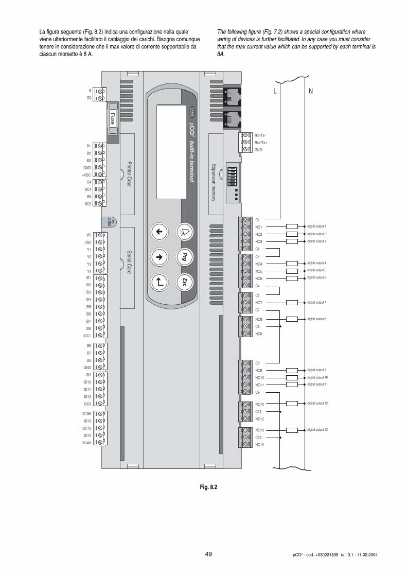
La figura seguente (Fig. 8.2) indica una configurazione nella qualeviene ulteriormente facilitato il cablaggio dei carichi. Bisogna comunquetenere in considerazione che il max valore di corrente sopportabile daciascun morsetto è 8 A.
The following figure (Fig. 7.2) shows a special configuration wherewiring of devices is further facilitated. In any case you must considerthat the max current value which can be supported by each terminal is8A.
49 pCO2 - cod. +030221835 rel. 3.1 - 11.02.2004
digital output 1
digital output 2
digital output 3
digital output 4
digital output 5
digital output 6
digital output 7
digital output 8
digital output 9
digital output 10
digital output 11
digital output 12
digital output 13
C1
NO1
NO2
NO3
C1
C4
NO4
NO5
NO6
C4
C7
NO7
C7
NO8
C8
NC8
NO12
C12
NC12
NO13
C13
NC13
C9
NO9
NO10
NO11
C9
G
G0
B1
B2
B3
GND
+VDC
B4
BC4
B5
BC5
VG
VG0
Y1
Y2
Y3
Y4
ID1
ID2
ID3
ID4
ID5
ID6
ID7
ID8
IDC1
B6
B7
B8
GND
ID9
ID10
ID11
ID12
IDC9
ID13H
ID13
IDC13
ID14
ID14H
Rx-/Tx-
Rx+/Tx+
GND
Fuse
Expansion mem
ory
built-in terminal
Printer Crad
Serial Card
L N
Fig. 8.2
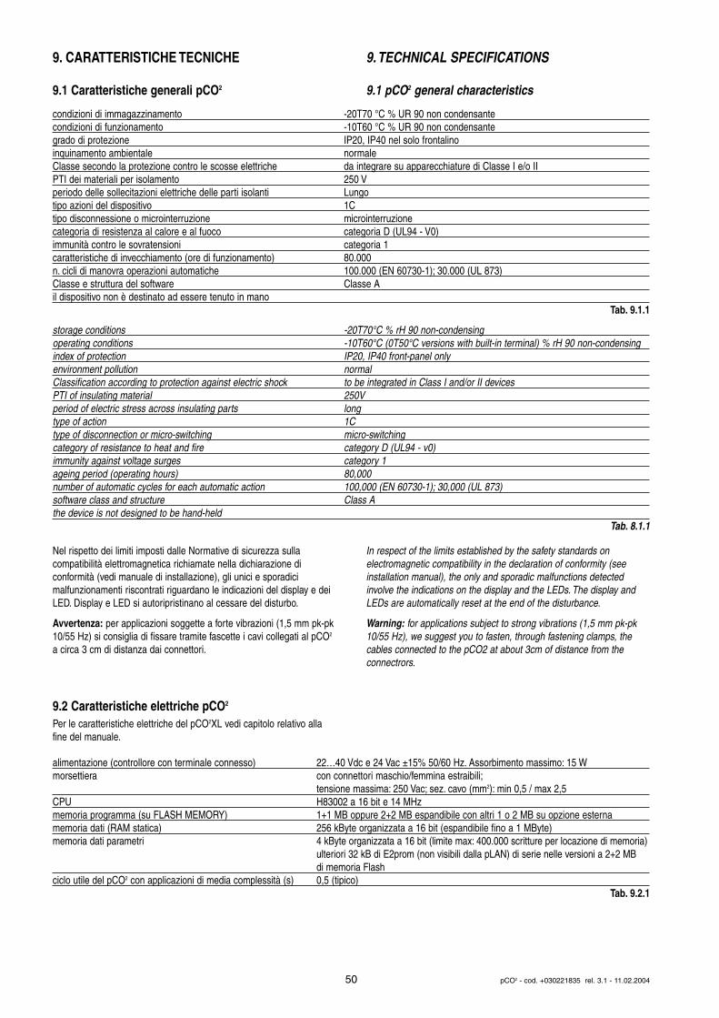
9. CARATTERISTICHE TECNICHE
9.1 Caratteristiche generali pCO2
Nel rispetto dei limiti imposti dalle Normative di sicurezza sulla compatibilità elettromagnetica richiamate nella dichiarazione di conformità (vedi manuale di installazione), gli unici e sporadici malfunzionamenti riscontrati riguardano le indicazioni del display e deiLED. Display e LED si autoripristinano al cessare del disturbo.
Avvertenza: per applicazioni soggette a forte vibrazioni (1,5 mm pk-pk10/55 Hz) si consiglia di fissare tramite fascette i cavi collegati al pCO2
a circa 3 cm di distanza dai connettori.
9.2 Caratteristiche elettriche pCO2
Per le caratteristiche elettriche del pCO2XL vedi capitolo relativo allafine del manuale.
9.TECHNICAL SPECIFICATIONS
9.1 pCO2 general characteristics
In respect of the limits established by the safety standards on electromagnetic compatibility in the declaration of conformity (seeinstallation manual), the only and sporadic malfunctions detected involve the indications on the display and the LEDs. The display andLEDs are automatically reset at the end of the disturbance.
Warning: for applications subject to strong vibrations (1,5 mm pk-pk10/55 Hz), we suggest you to fasten, through fastening clamps, thecables connected to the pCO2 at about 3cm of distance from the connectrors.
50 pCO2 - cod. +030221835 rel. 3.1 - 11.02.2004
condizioni di immagazzinamento -20T70 °C % UR 90 non condensantecondizioni di funzionamento -10T60 °C % UR 90 non condensantegrado di protezione IP20, IP40 nel solo frontalinoinquinamento ambientale normaleClasse secondo la protezione contro le scosse elettriche da integrare su apparecchiature di Classe I e/o IIPTI dei materiali per isolamento 250 Vperiodo delle sollecitazioni elettriche delle parti isolanti Lungotipo azioni del dispositivo 1Ctipo disconnessione o microinterruzione microinterruzionecategoria di resistenza al calore e al fuoco categoria D (UL94 - V0)immunità contro le sovratensioni categoria 1caratteristiche di invecchiamento (ore di funzionamento) 80.000n. cicli di manovra operazioni automatiche 100.000 (EN 60730-1); 30.000 (UL 873)Classe e struttura del software Classe Ail dispositivo non è destinato ad essere tenuto in mano
Tab. 9.1.1
storage conditions -20T70°C % rH 90 non-condensingoperating conditions -10T60°C (0T50°C versions with built-in terminal) % rH 90 non-condensingindex of protection IP20, IP40 front-panel only environment pollution normalClassification according to protection against electric shock to be integrated in Class I and/or II devicesPTI of insulating material 250Vperiod of electric stress across insulating parts longtype of action 1Ctype of disconnection or micro-switching micro-switchingcategory of resistance to heat and fire category D (UL94 - v0)immunity against voltage surges category 1ageing period (operating hours) 80,000number of automatic cycles for each automatic action 100,000 (EN 60730-1); 30,000 (UL 873)software class and structure Class Athe device is not designed to be hand-held
Tab. 8.1.1
alimentazione (controllore con terminale connesso) 22…40 Vdc e 24 Vac ±15% 50/60 Hz. Assorbimento massimo: 15 W morsettiera con connettori maschio/femmina estraibili;
tensione massima: 250 Vac; sez. cavo (mm2): min 0,5 / max 2,5CPU H83002 a 16 bit e 14 MHzmemoria programma (su FLASH MEMORY) 1+1 MB oppure 2+2 MB espandibile con altri 1 o 2 MB su opzione esternamemoria dati (RAM statica) 256 kByte organizzata a 16 bit (espandibile fino a 1 MByte)memoria dati parametri 4 kByte organizzata a 16 bit (limite max: 400.000 scritture per locazione di memoria)
ulteriori 32 kB di E2prom (non visibili dalla pLAN) di serie nelle versioni a 2+2 MB di memoria Flash
ciclo utile del pCO2 con applicazioni di media complessità (s) 0,5 (tipico)Tab. 9.2.1
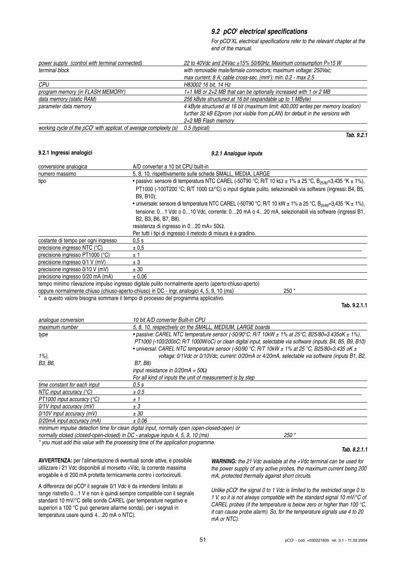
9.2.1 Ingressi analogici
AVVERTENZA: per l’alimentazione di eventuali sonde attive, è possibileutilizzare i 21 Vdc disponibili al morsetto +Vdc, la corrente massimaerogabile è di 200 mA protetta termicamente contro i cortocircuiti.
A differenza del pCOB il segnale 0/1 Vdc è da intendersi limitato alrange ristretto 0…1 V e non è quindi sempre compatibile con il segnalestandard 10 mV/°C delle sonde CAREL (per temperature negative esuperiori a 100 °C può generare allarme sonda), per i segnali in temperatura usare quindi 4…20 mA o NTC).
9.2 pCO2 electrical specificationsFor pCO2XL electrical specifications refer to the relevant chapter at theend of the manual.
9.2.1 Analogue inputs
WARNING: the 21 Vdc available at the +Vdc terminal can be used forthe power supply of any active probes, the maximum current being 200mA, protected thermally against short circuits.
Unlike pCOB the signal 0 to 1 Vdc is limited to the restricted range 0 to1 V, so it is not always compatible with the standard signal 10 mV/°C ofCAREL probes (if the temperature is below zero or higher than 100 °C,it can cause probe alarm). So, for the temperature signals use 4 to 20mA or NTC).
51 pCO2 - cod. +030221835 rel. 3.1 - 11.02.2004
power supply (control with terminal connected) 22 to 40Vdc and 24Vac ±15% 50/60Hz. Maximum consumption P=15 W terminal block with removable male/female connectors; maximum voltage: 250Vac;
max current: 8 A; cable cross-sec. (mm2): min. 0.2 - max 2.5CPU H83002 16 bit, 14 Hz program memory (in FLASH MEMORY) 1+1 MB or 2+2 MB that can be optionally increased with 1 or 2 MBdata memory (static RAM) 256 kByte structured at 16 bit (expandable up to 1 MByte)parameter data memory 4 kByte structured at 16 bit (maximum limit: 400,000 writes per memory location)
further 32 kB E2prom (not visible from pLAN) for default in the versions with 2+2 MB Flash memory
working cycle of the pCO2 with applicat. of average complexity (s) 0.5 (typical)Tab. 9.2.1
conversione analogica A/D converter a 10 bit CPU built-innumero massimo 5, 8, 10, rispettivamente sulle schede SMALL, MEDIA, LARGEtipo • passivo: sensore di temperatura NTC CAREL (-50T90 °C; R/T 10 kΩ ± 1% a 25 °C, B25/80=3,435 °K ± 1%),
PT1000 (-100T200 °C; R/T 1000 Ω/°C) o input digitale pulito, selezionabili via software (ingressi: B4, B5, B9, B10);
• universale: sensore di temperatura NTC CAREL (-50T90 °C; R/T 10 kW ± 1% a 25 °C, B25/80=3,435 °K ± 1%), tensione: 0…1 Vdc o 0…10 Vdc, corrente: 0…20 mA o 4…20 mA, selezionabili via software (ingressi B1, B2, B3, B6, B7, B8).
resistenza di ingresso in 0…20 mA= 50Ω.Per tutti i tipi di ingresso il metodo di misura è a gradino.
costante di tempo per ogni ingresso 0,5 sprecisione ingresso NTC (°C) ± 0,5precisione ingresso PT1000 (°C) ± 1precisione ingresso 0/1 V (mV) ± 3precisione ingresso 0/10 V (mV) ± 30precisione ingresso 0/20 mA (mA) ± 0,06tempo minimo rilevazione impulso ingresso digitale pulito normalmente aperto (aperto-chiuso-aperto) oppure normalmente chiuso (chiuso-aperto-chiuso) in DC - ingr. analogici 4, 5, 9, 10 (ms) 250 ** a questo valore bisogna sommare il tempo di processo del programma applicativo.
Tab. 9.2.1.1
analogue conversion 10 bit A/D converter Built-in CPUmaximum number 5, 8, 10, respectively on the SMALL, MEDIUM, LARGE boardstype • passive: CAREL NTC temperature sensor (-50/90°C; R/T 10kW ± 1% at 25°C, B25/80=3.435oK ± 1%),
PT1000 (-100/200oC; R/T 1000W/oC) or clean digital input, selectable via software (inputs: B4, B5, B9, B10)• universal: CAREL NTC temperature sensor (-50/90 °C; R/T 10kW ± 1% at 25 °C, B25/80=3,435 oK ±
1%), voltage: 0/1Vdc or 0/10Vdc, current: 0/20mA or 4/20mA, selectable via software (inputs B1, B2,B3, B6, B7, B8)
input resistance in 0/20mA = 50ΩFor all kind of inputs the unit of measurement is by step
time constant for each input 0.5 sNTC input accuracy (°C) ± 0.5PT1000 input accuracy (°C) ± 10/1V input accuracy (mV) ± 30/10V input accuracy (mV) ± 300/20mA input accuracy (mA) ± 0.06minimum impulse detection time for clean digital input, normally open (open-closed-open) or normally closed (closed-open-closed) in DC - analogue inputs 4, 5, 9, 10 (ms) 250 ** you must add this value with the processing time of the application programme.
Tab. 8.2.1.1
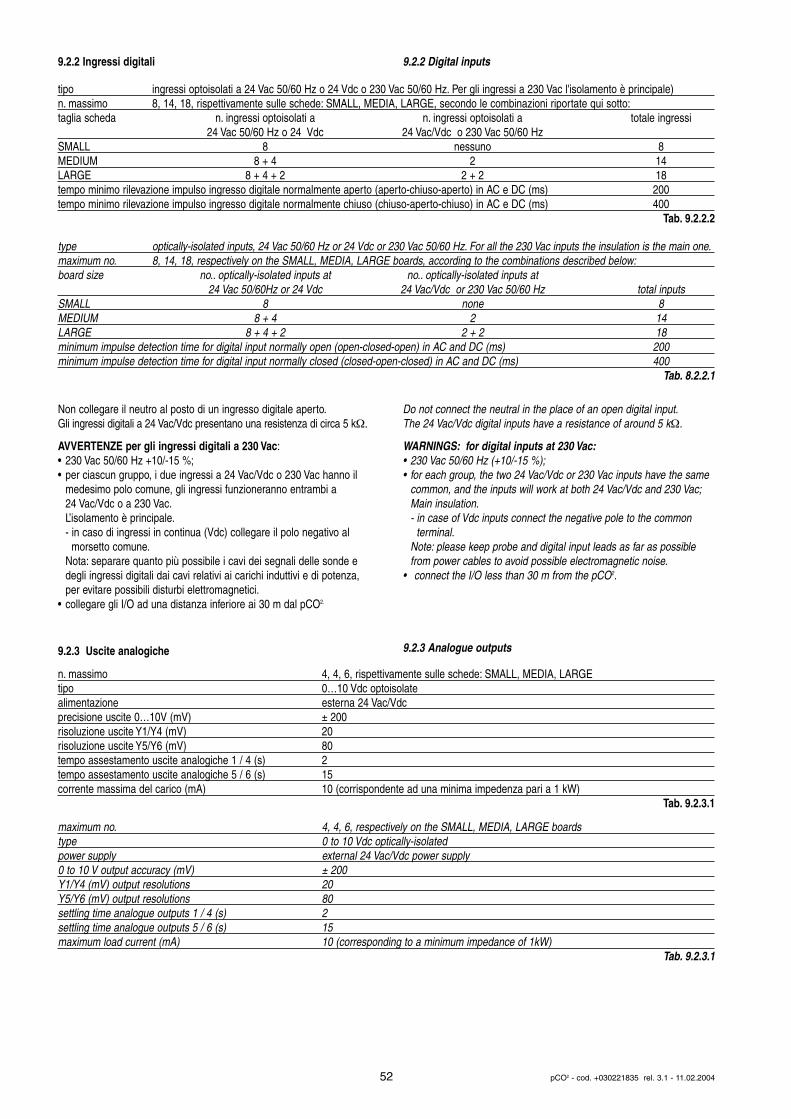
9.2.2 Ingressi digitali
Non collegare il neutro al posto di un ingresso digitale aperto.Gli ingressi digitali a 24 Vac/Vdc presentano una resistenza di circa 5 kΩ.
AVVERTENZE per gli ingressi digitali a 230 Vac:• 230 Vac 50/60 Hz +10/-15 %;• per ciascun gruppo, i due ingressi a 24 Vac/Vdc o 230 Vac hanno il
medesimo polo comune, gli ingressi funzioneranno entrambi a 24 Vac/Vdc o a 230 Vac.L’isolamento è principale.- in caso di ingressi in continua (Vdc) collegare il polo negativo al
morsetto comune.Nota: separare quanto più possibile i cavi dei segnali delle sonde e degli ingressi digitali dai cavi relativi ai carichi induttivi e di potenza, per evitare possibili disturbi elettromagnetici.
• collegare gli I/O ad una distanza inferiore ai 30 m dal pCO2.
9.2.3 Uscite analogiche
9.2.2 Digital inputs
Do not connect the neutral in the place of an open digital input.The 24 Vac/Vdc digital inputs have a resistance of around 5 kΩ.
WARNINGS: for digital inputs at 230 Vac:• 230 Vac 50/60 Hz (+10/-15 %);• for each group, the two 24 Vac/Vdc or 230 Vac inputs have the same
common, and the inputs will work at both 24 Vac/Vdc and 230 Vac;Main insulation.- in case of Vdc inputs connect the negative pole to the common
terminal.Note: please keep probe and digital input leads as far as possible from power cables to avoid possible electromagnetic noise.
• connect the I/O less than 30 m from the pCO2.
9.2.3 Analogue outputs
52 pCO2 - cod. +030221835 rel. 3.1 - 11.02.2004
type optically-isolated inputs, 24 Vac 50/60 Hz or 24 Vdc or 230 Vac 50/60 Hz. For all the 230 Vac inputs the insulation is the main one.maximum no. 8, 14, 18, respectively on the SMALL, MEDIA, LARGE boards, according to the combinations described below:board size no.. optically-isolated inputs at no.. optically-isolated inputs at
24 Vac 50/60Hz or 24 Vdc 24 Vac/Vdc or 230 Vac 50/60 Hz total inputsSMALL 8 none 8MEDIUM 8 + 4 2 14LARGE 8 + 4 + 2 2 + 2 18minimum impulse detection time for digital input normally open (open-closed-open) in AC and DC (ms) 200minimum impulse detection time for digital input normally closed (closed-open-closed) in AC and DC (ms) 400
Tab. 8.2.2.1
n. massimo 4, 4, 6, rispettivamente sulle schede: SMALL, MEDIA, LARGEtipo 0…10 Vdc optoisolatealimentazione esterna 24 Vac/Vdcprecisione uscite 0…10V (mV) ± 200risoluzione uscite Y1/Y4 (mV) 20risoluzione uscite Y5/Y6 (mV) 80tempo assestamento uscite analogiche 1 / 4 (s) 2tempo assestamento uscite analogiche 5 / 6 (s) 15corrente massima del carico (mA) 10 (corrispondente ad una minima impedenza pari a 1 kW)
Tab. 9.2.3.1
maximum no. 4, 4, 6, respectively on the SMALL, MEDIA, LARGE boardstype 0 to 10 Vdc optically-isolatedpower supply external 24 Vac/Vdc power supply0 to 10 V output accuracy (mV) ± 200Y1/Y4 (mV) output resolutions 20Y5/Y6 (mV) output resolutions 80settling time analogue outputs 1 / 4 (s) 2settling time analogue outputs 5 / 6 (s) 15maximum load current (mA) 10 (corresponding to a minimum impedance of 1kW)
Tab. 9.2.3.1
tipo ingressi optoisolati a 24 Vac 50/60 Hz o 24 Vdc o 230 Vac 50/60 Hz. Per gli ingressi a 230 Vac l'isolamento è principale)n. massimo 8, 14, 18, rispettivamente sulle schede: SMALL, MEDIA, LARGE, secondo le combinazioni riportate qui sotto:taglia scheda n. ingressi optoisolati a n. ingressi optoisolati a totale ingressi
24 Vac 50/60 Hz o 24 Vdc 24 Vac/Vdc o 230 Vac 50/60 HzSMALL 8 nessuno 8MEDIUM 8 + 4 2 14LARGE 8 + 4 + 2 2 + 2 18tempo minimo rilevazione impulso ingresso digitale normalmente aperto (aperto-chiuso-aperto) in AC e DC (ms) 200tempo minimo rilevazione impulso ingresso digitale normalmente chiuso (chiuso-aperto-chiuso) in AC e DC (ms) 400
Tab. 9.2.2.2
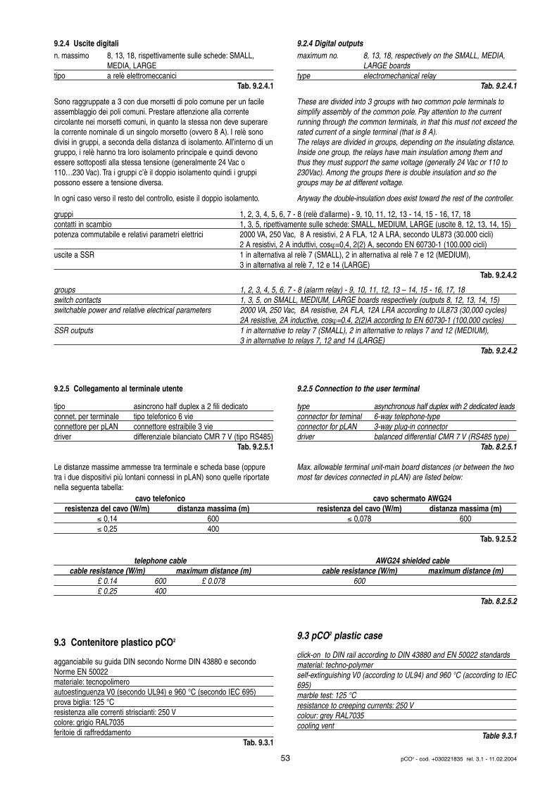
9.2.4 Uscite digitalin. massimo 8, 13, 18, rispettivamente sulle schede: SMALL,
MEDIA, LARGEtipo a relè elettromeccanici
Tab. 9.2.4.1
Sono raggruppate a 3 con due morsetti di polo comune per un facileassemblaggio dei poli comuni. Prestare attenzione alla corrente circolante nei morsetti comuni, in quanto la stessa non deve superarela corrente nominale di un singolo morsetto (ovvero 8 A). I relè sonodivisi in gruppi, a seconda della distanza di isolamento. All’interno di ungruppo, i relè hanno tra loro isolamento principale e quindi devonoessere sottoposti alla stessa tensione (generalmente 24 Vac o110…230 Vac). Tra i gruppi c’è il doppio isolamento quindi i gruppi possono essere a tensione diversa.
In ogni caso verso il resto del controllo, esiste il doppio isolamento.
9.2.5 Collegamento al terminale utente
tipo asincrono half duplex a 2 fili dedicatoconnet. per terminale tipo telefonico 6 vieconnettore per pLAN connettore estraibile 3 viedriver differenziale bilanciato CMR 7 V (tipo RS485)
Tab. 9.2.5.1
Le distanze massime ammesse tra terminale e scheda base (oppuretra i due dispositivi più lontani connessi in pLAN) sono quelle riportatenella seguenta tabella:
9.3 Contenitore plastico pCO2
agganciabile su guida DIN secondo Norme DIN 43880 e secondoNorme EN 50022materiale: tecnopolimeroautoestinguenza V0 (secondo UL94) e 960 °C (secondo IEC 695)prova biglia: 125 °Cresistenza alle correnti striscianti: 250 Vcolore: grigio RAL7035feritoie di raffreddamento
Tab. 9.3.1
9.2.4 Digital outputsmaximum no. 8, 13, 18, respectively on the SMALL, MEDIA,
LARGE boardstype electromechanical relay
Tab. 9.2.4.1
These are divided into 3 groups with two common pole terminals tosimplify assembly of the common pole. Pay attention to the current running through the common terminals, in that this must not exceed therated current of a single terminal (that is 8 A).The relays are divided in groups, depending on the insulating distance.Inside one group, the relays have main insulation among them andthus they must support the same voltage (generally 24 Vac or 110 to230Vac). Among the groups there is double insulation and so the groups may be at different voltage.
Anyway the double-insulation does exist toward the rest of the controller.
9.2.5 Connection to the user terminal
type asynchronous half duplex with 2 dedicated leads connector for teminal 6-way telephone-typeconnector for pLAN 3-way plug-in connectordriver balanced differential CMR 7 V (RS485 type)
Tab. 8.2.5.1
Max. allowable terminal unit-main board distances (or between the twomost far devices connected in pLAN) are listed below:
9.3 pCO2 plastic case
click-on to DIN rail according to DIN 43880 and EN 50022 standardsmaterial: techno-polymerself-extinguishing V0 (according to UL94) and 960 °C (according to IEC695)marble test: 125 °Cresistance to creeping currents: 250 Vcolour: grey RAL7035cooling vent
Table 9.3.1
53 pCO2 - cod. +030221835 rel. 3.1 - 11.02.2004
groups 1, 2, 3, 4, 5, 6, 7 - 8 (alarm relay) - 9, 10, 11, 12, 13 – 14, 15 - 16, 17, 18switch contacts 1, 3, 5, on SMALL, MEDIUM, LARGE boards respectively (outputs 8, 12, 13, 14, 15)switchable power and relative electrical parameters 2000 VA, 250 Vac, 8A resistive, 2A FLA, 12A LRA according to UL873 (30,000 cycles)
2A resistive, 2A inductive, cosϕ=0.4, 2(2)A according to EN 60730-1 (100,000 cycles)SSR outputs 1 in alternative to relay 7 (SMALL), 2 in alternative to relays 7 and 12 (MEDIUM),
3 in alternative to relays 7, 12 and 14 (LARGE)Tab. 9.2.4.2
gruppi 1, 2, 3, 4, 5, 6, 7 - 8 (relè d'allarme) - 9, 10, 11, 12, 13 - 14, 15 - 16, 17, 18contatti in scambio 1, 3, 5, ripettivamente sulle schede: SMALL, MEDIUM, LARGE (uscite 8, 12, 13, 14, 15)potenza commutabile e relativi parametri elettrici 2000 VA, 250 Vac, 8 A resistivi, 2 A FLA, 12 A LRA, secondo UL873 (30.000 cicli)
2 A resistivi, 2 A induttivi, cosϕ=0,4, 2(2) A, secondo EN 60730-1 (100.000 cicli)uscite a SSR 1 in alternativa al relè 7 (SMALL), 2 in alternativa al relè 7 e 12 (MEDIUM),
3 in alternativa al relè 7, 12 e 14 (LARGE)Tab. 9.2.4.2
cavo telefonico cavo schermato AWG24resistenza del cavo (W/m) distanza massima (m) resistenza del cavo (W/m) distanza massima (m)
≤ 0,14 600 ≤ 0,078 600≤ 0,25 400
Tab. 9.2.5.2
telephone cable AWG24 shielded cablecable resistance (W/m) maximum distance (m) cable resistance (W/m) maximum distance (m)
£ 0.14 600 £ 0.078 600£ 0.25 400
Tab. 8.2.5.2
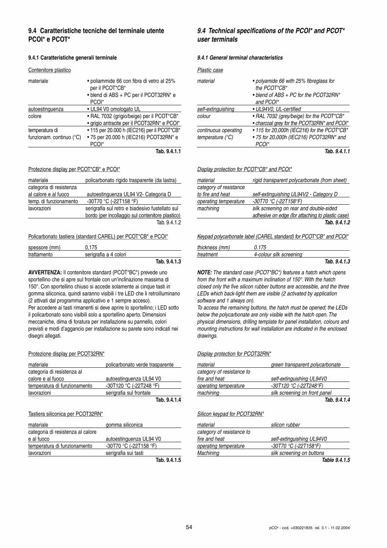
9.4 Caratteristiche tecniche del terminale utentePCOI* e PCOT*
9.4.1 Caratteristiche generali terminale
Contenitore plastico
materiale • poliammide 66 con fibra di vetro al 25% per il PCOT*CB*
• blend di ABS + PC per il PCOT32RN* e PCOI*
autoestinguenza • UL94 V0 omologato ULcolore • RAL 7032 (grigio/beige) per il PCOT*CB*
• grigio antracite per il PCOT32RN* e PCOI*temperatura di • 115 per 20.000 h (IEC216) per il PCOT*CB*funzionam. continuo (°C) • 75 per 20.000 h (IEC216) PCOT32RN* e
PCOI*Tab. 9.4.1.1
Protezione display per PCOT*CB* e PCOI*
materiale policarbonato rigido trasparente (da lastra)categoria di resistenzaal calore e al fuoco autoestinguenza UL94 V2- Categoria Dtemp. di funzionamento -30T70 °C (-22T158 °F)lavorazioni serigrafia sul retro e biadesivo fustellato sul
bordo (per incollaggio sul contenitore plastico)Tab. 9.4.1.2
Policarbonato tastiera (standard CAREL) per PCOT*CB* e PCOI*
spessore (mm) 0,175trattamento serigrafia a 4 colori
Tab. 9.4.1.3
AVVERTENZA: Il contenitore standard (PCOT*BC*) prevede uno sportellino che si apre sul frontale con un’inclinazione massima di150°. Con sportellino chiuso si accede solamente ai cinque tasti ingomma siliconica, quindi saranno visibili i tre LED che li retroilluminano(2 attivati dal programma applicativo e 1 sempre acceso).Per accedere ai tasti rimanenti si deve aprire lo sportellino; i LED sottoil policarbonato sono visibili solo a sportellino aperto. Dimensioni meccaniche, dima di foratura per installazione su pannello, colori previsti e modi d’aggancio per installazione su parete sono indicati neidisegni allegati.
Protezione display per PCOT32RN*
materiale policarbonato verde trasparente categoria di resistenza al calore e al fuoco autoestinguenza UL94 V0temperatura di funzionamento -30T120 °C (-22T248 °F)lavorazioni serigrafia sul frontale
Tab. 9.4.1.4
Tastiera siliconica per PCOT32RN*
materiale gomma siliconicacategoria di resistenza al calore e al fuoco autoestinguenza UL94 V0temperatura di funzionamento -30T70 °C (-22T158 °F)lavorazioni serigrafia sui tasti
Tab. 9.4.1.5
9.4 Technical specifications of the PCOI* and PCOT*user terminals
9.4.1 General terminal characteristics
Plastic case
material • polyamide 66 with 25% fibreglass for the PCOT*CB*
• blend of ABS + PC for the PCOT32RN* and PCOI*
self-extinguishing • UL94V0, UL-certifiedcolour • RAL 7032 (grey/beige) for the PCOT*CB*
• charcoal grey for the PCOT32RN* and PCOI*continuous operating • 115 for 20,000h (IEC216) for the PCOT*CB*temperature (°C) • 75 for 20,000h (IEC216) PCOT32RN* and
PCOI*Tab. 9.4.1.1
Display protection for PCOT*CB* and PCOI*
material rigid transparent polycarbonate (from sheet)category of resistance to fire and heat self-extinguishing UL94V2 - Category Doperating temperature -30T70 °C (-22T158°F)machining silk screening on rear and double-sided
adhesive on edge (for attaching to plastic case)Tab. 9.4.1.2
Keypad polycarbonate label (CAREL standard) for PCOT*CB* and PCOI*
thickness (mm) 0.175treatment 4-colour silk screening
Tab. 9.4.1.3
NOTE: The standard case (PCOT*BC*) features a hatch which opensfrom the front with a maximum inclination of 150°. With the hatch closed only the five silicon rubber buttons are accessible, and the threeLEDs which back-light them are visible (2 activated by applicationsoftware and 1 always on).To access the remaining buttons, the hatch must be opened; the LEDsbelow the polycarbonate are only visible with the hatch open. The physical dimensions, drilling template for panel installation, colours andmounting instructions for wall installation are indicated in the encloseddrawings.
Display protection for PCOT32RN*
material green transparent polycarbonate category of resistance to fire and heat self-extinguishing UL94V0operating temperature -30T120 °C (-22T248°F)machining silk screening on front panel
Tab. 9.4.1.4
Silicon keypad for PCOT32RN*
material silicon rubbercategory of resistance to fire and heat self-extinguishing UL94V0operating temperature -30T70 °C (-22T158°F)Machining silk screening on buttons
Table 9.4.1.5
54 pCO2 - cod. +030221835 rel. 3.1 - 11.02.2004
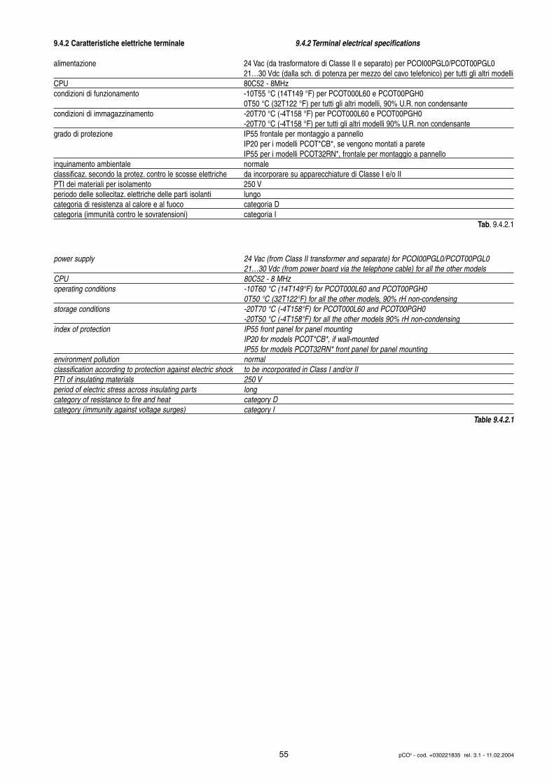
9.4.2 Caratteristiche elettriche terminale 9.4.2 Terminal electrical specifications
55 pCO2 - cod. +030221835 rel. 3.1 - 11.02.2004
alimentazione 24 Vac (da trasformatore di Classe II e separato) per PCOI00PGL0/PCOT00PGL021…30 Vdc (dalla sch. di potenza per mezzo del cavo telefonico) per tutti gli altri modelli
CPU 80C52 - 8MHzcondizioni di funzionamento -10T55 °C (14T149 °F) per PCOT000L60 e PCOT00PGH0
0T50 °C (32T122 °F) per tutti gli altri modelli, 90% U.R. non condensantecondizioni di immagazzinamento -20T70 °C (-4T158 °F) per PCOT000L60 e PCOT00PGH0
-20T70 °C (-4T158 °F) per tutti gli altri modelli 90% U.R. non condensantegrado di protezione IP55 frontale per montaggio a pannello
IP20 per i modelli PCOT*CB*, se vengono montati a pareteIP55 per i modelli PCOT32RN*, frontale per montaggio a pannello
inquinamento ambientale normaleclassificaz. secondo la protez. contro le scosse elettriche da incorporare su apparecchiature di Classe I e/o IIPTI dei materiali per isolamento 250 Vperiodo delle sollecitaz. elettriche delle parti isolanti lungocategoria di resistenza al calore e al fuoco categoria Dcategoria (immunità contro le sovratensioni) categoria I
Tab. 9.4.2.1
power supply 24 Vac (from Class II transformer and separate) for PCOI00PGL0/PCOT00PGL021…30 Vdc (from power board via the telephone cable) for all the other models
CPU 80C52 - 8 MHzoperating conditions -10T60 °C (14T149°F) for PCOT000L60 and PCOT00PGH0
0T50 °C (32T122°F) for all the other models, 90% rH non-condensingstorage conditions -20T70 °C (-4T158°F) for PCOT000L60 and PCOT00PGH0
-20T50 °C (-4T158°F) for all the other models 90% rH non-condensingindex of protection IP55 front panel for panel mounting
IP20 for models PCOT*CB*, if wall-mountedIP55 for models PCOT32RN* front panel for panel mounting
environment pollution normalclassification according to protection against electric shock to be incorporated in Class I and/or IIPTI of insulating materials 250 Vperiod of electric stress across insulating parts longcategory of resistance to fire and heat category Dcategory (immunity against voltage surges) category I
Table 9.4.2.1
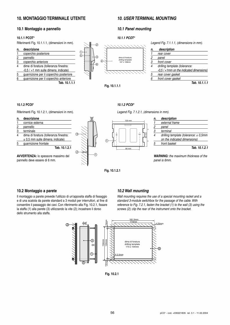
10. MONTAGGIO TERMINALE UTENTE
10.1 Montaggio a pannello
10.1.1 PCOT*Riferimenti Fig. 10.1.1.1, (dimensioni in mm).
n. descrizione1 coperchio posteriore2 pannello3 coperchio anteriore4 dime di foratura (tolleranza finestra:
-0,5 / +1 mm sulle dimens. indicate)5 guarnizione per il coperchio posteriore6 guarnizione per il coperchio anteriore
Tab. 10.1.1.1
10.1.2 PCOI*
Riferimenti Fig. 10.1.2.1, (dimensioni in mm).
n. descrizione1 cornice esterna2 pannello3 terminale4 dima di foratura (tolleranza finestra:
± 0,5 mm sulle dimens. indicate)5 guarnizione frontale
Tab. 10.1.2.1
AVVERTENZA: lo spessore massimo delpannello deve essere di 6 mm.
10.2 Montaggio a pareteIl montaggio a parete prevede l'utilizzo di un'apposita staffa di fissaggioe di una scatola da parete standard a 3 moduli per interruttori, al fine diconsentire il passaggio dei cavi. Con riferimento alla Fig. 10.2.1, fissarela staffa (1) alla parete (3) utilizzando la vite (2); incastrare il dorsodello strumento alla staffa.
10. USER TERMINAL MOUNTING
10.1 Panel mounting
10.1.1 PCOT*Legend Fig. 7.1.1.1, (dimensions in mm).
n. description1 rear cover2 panel3 front cover4 drilling template (tolerance:
-0,5 / +1mm on the indicated dimensions)5 rear cover gasket6 front cover gasket
Tab. 10.1.1.1
10.1.2 PCOI*
Legend Fig. 7.1.2.1, (dimensions in mm).
n. description1 external frame2 panel3 terminal 4 drilling template (tolerance: ± 0,5mm
on the indicated dimensions)5 front basket
Tab. 10.1.2.1
WARNING: the maximum thickness of thepanel is 6mm.
10.2 Wall mountingWall mounting requires the use of a special mounting racket and astandard 3-module switchbox for the passage of the cable. With reference to Fig. 7.2.1, fasten the bracket (1) to the wall (3) using thescrews (2); clip the rear of the instrument onto the bracket.
56 pCO2 - cod. +030221835 rel. 3.1 - 11.02.2004
dima di foraturadrilling template167 x 108mm
1
5
2
3
64
84 mm
80 m
m
120 mm
==
2
3
1
1
dima di foraturadrilling template173 x 154mm12
4mm
181.5mm
15m
m
4.25mm
fl 2.5mm
15m
m15
4mm
173mm2
3
1
5
4
Fig. 10.1.1.1
Fig. 10.1.2.1
Fig. 10.2.1
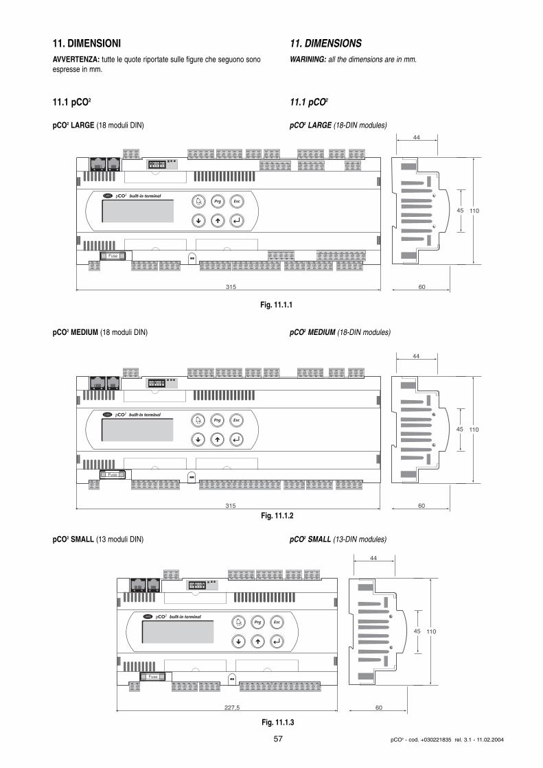
11. DIMENSIONIAVVERTENZA: tutte le quote riportate sulle figure che seguono sonoespresse in mm.
11.1 pCO2
pCO2 LARGE (18 moduli DIN)
pCO2 MEDIUM (18 moduli DIN)
pCO2 SMALL (13 moduli DIN)
11. DIMENSIONSWARINING: all the dimensions are in mm.
11.1 pCO2
pCO2 LARGE (18-DIN modules)
pCO2 MEDIUM (18-DIN modules)
pCO2 SMALL (13-DIN modules)
57 pCO2 - cod. +030221835 rel. 3.1 - 11.02.2004
Fuse
60
110
315
45
44
built-in terminal
Fuse
60
110
315
45
44
built-in terminal
Fuse
60
110
227,5
45
44
built-in terminal
Fig. 11.1.1
Fig. 11.1.2
Fig. 11.1.3
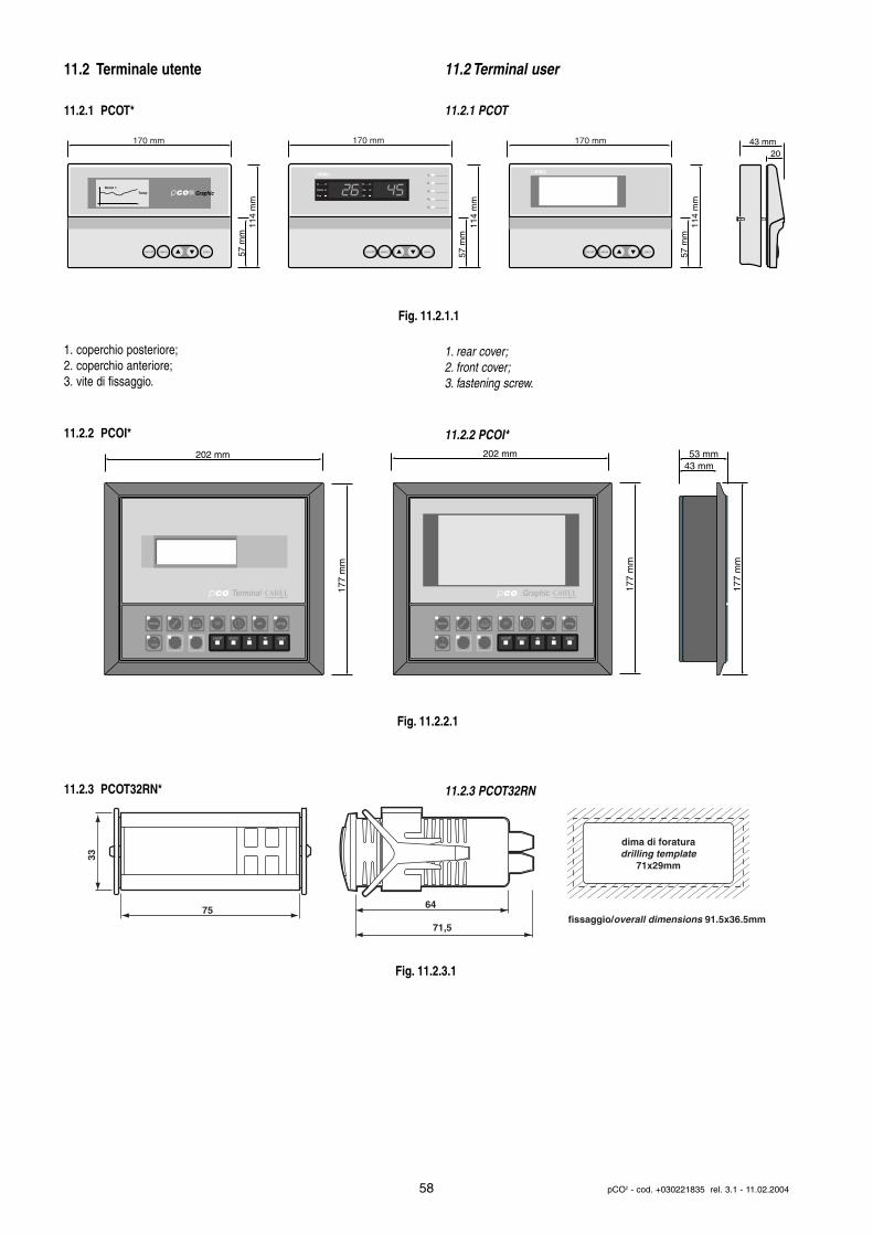
11.2 Terminale utente
11.2.1 PCOT*
1. coperchio posteriore;2. coperchio anteriore;3. vite di fissaggio.
11.2.2 PCOI*
11.2.3 PCOT32RN*
11.2 Terminal user
11.2.1 PCOT
1. rear cover;2. front cover;3. fastening screw.
11.2.2 PCOI*
11.2.3 PCOT32RN
58 pCO2 - cod. +030221835 rel. 3.1 - 11.02.2004
on/off alarm enter
GraphicRoom 1
Temp
on/off alarm enter
A____
Parem
Psw
B____
Val
AL
1_ __________
2_ __________
3_ __________
4_ __________
5_ __________
on/off alarm enter
170 mm
57 m
m11
4 m
m
170 mm
57 m
m11
4 m
m
170 mm
57 m
m11
4 m
m
43 mm 20
on/off alarm enter
menu I/O set prog.
?info
Terminal
on/off alarm enter
menu I/O set prog.
?info
Graphic
53 mm43 mm
202 mm
177
mm
202 mm
177
mm
177
mm
75
33
dima di foraturadrilling template
71x29mm
fissaggio/overall dimensions 91.5x36.5mm
64
71,5
Fig. 11.2.1.1
Fig. 11.2.2.1
Fig. 11.2.3.1
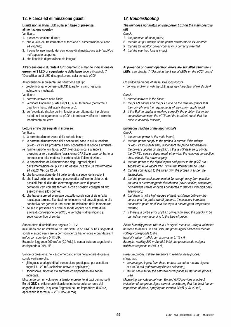
12. Ricerca ed eliminazione guastiL’unità non si avvia (LED sulla sch base di presenza alimentazione spento)Verificare:1. presenza tensione di rete;2. che a valle del trasformatore di tensione di alimentazione vi siano
24 Vac/Vdc;3. il corretto inserimento del connettore di alimentazione a 24 Vac/Vdc
nell’apposito supporto;4. che il fusibile di protezione sia integro;
All’accensione o durante il funzionamento si hanno indicazione dierrore nei 3 LED di segnalazione della base vedere il capitolo 7”Decodifica dei 3 LED di segnalazione sulla scheda pCO2
All’accensione si presenta una situazione del tipo• problemi di vario genere sull’LCD (caratteri strani, nessuna
indicazione mostrata);Verificare:1. corretto software nella flash;2. verificare l’indirizzo pLAN sul pCO2 e sul terminale (conforme a
quanto richiesto dall’applicativo in uso).3. se l’eventuale display built-in funziona correttamente, il problema
risiede nel collegamento tra pCO2 e terminale: verificare il corretto inserimento del cavo.
Letture errate dei segnali in ingressoVerificare:1. la corretta alimentazione della scheda base;2. la corretta alimentazione delle sonde: nel caso in cui la tensione
(+Vdc= 21 V) sia prossima a zero, sconnettere la sonda e rimisura-re l’alimentazione fornita dal pCO2. Nel caso in cui sia ancora
prossima a zero contattare l’assistenza CAREL; in caso contrario laconnessione tolta metteva in corto circiuto l’alimentazione.
3. la separazione dell’alimentazione degli ingressi digitali dall’alimentazione del pCO2. Può essere utilizzato un trasformatore 24 Vac/24 Vac da 12 VA.
4. che la connessione dei fili delle sonde sia secondo istruzioni 5. che i cavi delle sonde siano posizionati a sufficiente distanza da
possibili fonti di disturbo elettromagnetico (cavi di potenza, contattori, cavi con alte tensioni e con dispositivi collegati ad alto assorbimento allo spunto);
6. che tra sensore ed eventuale pozzetto sonda non vi sia un’alta resistenza termica. Eventualmente inserire nei pozzetti pasta o olio conduttivo per garantire una buona trasmissione della temperatura;
7. se si è in presenza di errore di sonda oppure se si tratta di un errore di conversione del pCO2, le verifiche si diversificano a seconda del tipo di sonda:
Sonde attive di umidità con segnale 0…1 V:misurando con un voltmetro tra i morsetti Bn ed GND si ha il segnale disonda e si puó verificare la corrispondenza tra tensione e grandezza: 1mVdc corrisponde a 0,1%U.R.Esempio: leggendo 200 mVdc (0,2 Vdc) la sonda invia un segnale checorrisponde a 20%U.R.
Sonde di pressione: nel caso emergano errori nella lettura di questesonde verificare che:• gli ingressi analogici di tali sonde siano predisposti per accettare
segnali 4…20 mA (selezione software applicativo);• i fondoscala impostati via software corrispondano alle sonde
impiegate.Misurando con un voltmetro la tensione presente ai capi dei morsettiBn ed GND si ottiene un’indicazione indiretta della corrente del segnale di sonda, in quanto l’ingresso ha una impedenza di 50 Ω,applicando la formula I= V/R (1V≡ 20 mA).
12.TroubleshootingThe unit does not switch on (the power LED on the main board isoff)Check:1. the presence of main power;2. that the output voltage of the power transformer is 24Vac/Vdc;3. that the 24Vac/Vdc power connector is correctly inserted;4. that the overload fuse is in tact;
At power on or during operation errors are signalled using the 3LEDs, see chapter 7 ”Decoding the 3 signal LEDs on the pCO2 board”
On switching on one of these situations occurs• general problems with the LCD (strange characters, blank display);
Check:1. correct software in the flash;2. the pLAN address on the pCO2 and on the terminal (check that
they comply with the requirements of the current application).3. if the Built-In display is working correctly, the problem lies in the
connection between the pCO2 and the terminal: check that the cable is correctly inserted;
Erroneous reading of the input signalsCheck:1. the correct power to the main board;2. that the power supply to the probes is correct: if the voltage
(+Vdc= 21 V) is near zero, disconnect the probe and measure the power supplied by the pCO2. If this is still near zero, contact the CAREL service department; otherwise, the removed connectionshort-circuits the power supply.
3. that the power to the digital inputs and power to the pCO2 are separated. A 24 Vac/24 Vac, 12 VA transformer can be used.
4. that the connection to the wires from the probes is as per the instructions;
5. that the probe cables are located far enough away from possible sources of electromagnetic disturbance (power cables, contactors, high-voltage cables or cables connected to devices with high peak absorption);
6. that there is not a high degree of heat resistance between the sensor and the probe cap (if present). If necessary introduce conductive paste or oil into the caps to ensure good temperature transfer;
7. if there is a probe error or pCO2 conversion error, the checks to be carried out vary according to the type of probe:
Active humidity probes with 0 to 1 V signal: measure, using a voltmeterbetween terminals Bn and GND, the probe signal and check that thevoltage corresponds to the humidity value: 1 mVdc corresponds to 0.1% r.H.Example: reading 200 mVdc (0.2 Vdc), the probe sends a signal which corresponds to 20% r.H.;
Pressure probes: if there are errors in reading these probes, check that:• the analogue inputs from these probes are set to receive signals
of 4 to 20 mA (software application selection);• the full scale set by the software corresponds to that of the probes
used.Measuring the voltage between Bn and GND provides a indirect indication of the probe signal current, considering that the input has animpedance of 50 Ω, applying the formula I=V/R (1V≡ 20 mA).
59 pCO2 - cod. +030221835 rel. 3.1 - 11.02.2004
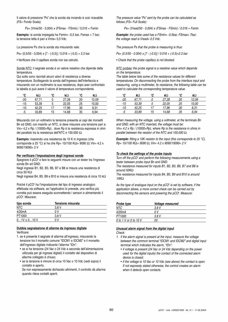
Il valore di pressione “Ps” che la sonda sta inviando è così ricavabile(FS= Fondo Scala):
Ps= (Vmis/50 - 0,004) x (FSmax - FSmin) / 0,016 + Fsmin
Esempio: la sonda impiegata ha Fsmin= -0,5 bar, Fsmax = 7 bar;la tensione letta è pari a Vmis= 0,5 Vdc.
La pressione Ps che la sonda sta misurando vale:
Ps= (0,5/50 - 0,004) x [7 - (-0,5)] / 0,016 + (-0,5) = 2,3 bar
• Verificare che il capillare sonda non sia ostruito.
Sonde NTC: il segnale sonda è un valore resistivo che dipende dallatemperatura.Qui sotto sono riportati alcuni valori di resistenza a diverse temperature. Scollegando la sonda dall’ingresso dell’interfaccia e misurando con un multimetro la sua resistenza, dopo aver confrontatola tabella si può avere il valore di temperatura corrispondente.
°C kΩ °C kΩ °C kΩ-20 67,71 0 27,28 20 12,09-15 53,39 5 22,05 25 10,00-10 42,25 17 17,96 30 8,31-5 33,89 15 14,68 35 6,94
Misurando con un voltmetro la tensione presente ai capi dei morsettiBn ed GND, con inserito un NTC, si deve misurare una tensione pari a:Vin= 4,2 x Rp / (10000+Rp) , dove Rp è la resistenza espressa in ohmdel parallelo tra la resistenza dell’NTC e 100.000 Ω.
Esempio: inserendo una resistenza da 10 K in ingresso (che corrisponde a 25 °C) si ha che Rp= 10//100 KΩ= 9090 Ω; Vin= 4,2 x9090/19090= 2 V
Per verificare l’impostazione degli ingressi sondeSpegnere il pCO2 e fare le seguenti misure con un tester tra l’ingressosonda Bn ed GND:Negli ingressi B1, B2, B3, B6, B7 e B8 si misura una resistenza dicirca 50 KΩNegli ingressi B4, B5, B9 e B10 si misura una resistenza di circa 10 kΩ
Poiché il pCO2 ha l’impostazione del tipo di ingresso analogico effettuata via software, se l’applicativo lo prevede, una verifica più corretta può essere eseguita sconnettendo i sensori e alimentando ilpCO2. Misurare:
tipo sonda Tensione misurataNTC 3,8 V4/20mA 0 VPT1000 3,8 V0…1V o 0…10 V 0 V
Dubbia segnalazione di allarme da ingresso digitaleVerificare:1. se è presente il segnale di allarme all’ingresso, misurando la
tensione tra il morsetto comune “IDCM1 e IDCM2” e il morsetto dell’ingresso digitale indicante l’allarme “IDn”:• se si ha tensione (24 Vac o 24 Vdc a seconda dell’alimentazione
utilizzata per gli ingressi digitali) il contatto del dispositivo diallarme collegato è chiuso;
• se la tensione è minore di circa 10 Vac o 10 Vdc (vedi sopra) il contatto è aperto.Se non espressamente dichiarato altrimenti, il controllo dà allarme quando rileva contatti aperti.
The pressure value “Ps” sent by the probe can be calculated as follows (FS= Full Scale):
Ps= (Vread/50 - 0.004) x (FSmax - FSmin) / 0.016 + Fsmin
Example: the probe used has a FSmin= -0.5bar, FSmax= 7bar;the voltage read is Vread= 0.5 Vdc.
The pressure Ps that the probe is measuring is thus:
Ps= (0.5/50 - 0.004) x [7 - (-0.5)] / 0.016 + (-0.5)=2.3 bar
• Check that the probe capillary is not blocked.
NTC probes: the probe signal is a resistive value which depends on the temperature.The table below lists some of the resistance values for different temperatures. On disconnecting the probe from the interface input andmeasuring, using a multimeter, its resistance, the following table can beused to calculate the corresponding temperature value.
°C kΩ °C kΩ °C kΩ-20 67,71 0 27,28 20 12,09-15 53,39 5 22,05 25 10,00-10 42,25 17 17,96 30 8,31-5 33,89 15 14,68 35 6,94
When measuring the voltage, using a voltmeter, at the terminals Bnand GND, with an NTC inserted, the voltage must be:Vin= 4.2 x Rp / (10000+Rp), where Rp is the resistance in ohms inparallel between the resistor of the NTC and 100,000 Ω.
Example: fitting a 10K resistor to the input (this corresponds to 25 °C),Rp= 10//100 KΩ= 9090 Ω; Vin= 4.2 x 9090/19090= 2 V
To check the settings of the probe inputsTurn off the pCO2 and perform the following measurements using atester between probe input Bn and GND:The resistance measured for inputs B1, B2, B3, B6, B7 and B8 isaround 50KΩThe resistance measured for inputs B4, B5, B9 and B10 is around10KΩ
As the type of analogue input on the pCO2 is set by software, if theapplication allows, a more correct check can be carried out by disconnecting the sensors and powering the pCO2. Measure:
Probe type Voltage measuredNTC 3.8 V4/20mA 0 VPT1000 3.8 V0 to 1 V or 0 to 10 V 0V
Unusual alarm signal from the digital inputCheck:1. if the alarm signal is present at the input, measure the voltage
between the common terminal “IDCM1 and IDCM2” and digital inputterminal which indicates the alarm, “IDn”:• if voltage is present (24 Vac or 24 Vdc depending on the power
used for the digital inputs) the contact of the connected alarm device is closed;
• if the voltage is 10 Vac or 10 Vdc (see above) the contact is open.If not expressly stated otherwise, the control creates an alarm when it detects open contacts.
60 pCO2 - cod. +030221835 rel. 3.1 - 11.02.2004
Il pCO2 continua ripetutamente ad andare in Watch-dog, cioè sispegne e si riaccende come se per qualche secondo mancassel’alimentazione o attiva casualmente alcune uscite (digitali e/oanalogiche)Verificare:1. che i cavi di potenza non passino nelle vicinanze dei
microprocessori della scheda base;2. che il dimensionamento del trasformatore di alimentazione (non
fornito da CAREL) sia corretto (vedi paragrafo ALIMENTAZIONE);3. che siano mantenuti separati i cavi sonda ingresso digitali dagli altri
cavi (quadro più canaline)
La connessione seriale con supervisore locale non funzionaVerificare:1. la presenza e la corretta connessione della schedina seriale codice
PCO20048502. che il numero di identificazione dell’unità pCO2 sia stato impostato
correttamente (vedi manuali dei programmi applicativi);3. che i cavi seriali siano connessi in modo corretto secondo lo
schema CAREL riportato nella documentazione relativa alla rete di supervisione;
La connessione con supervisore remoto non funzionaVerificare:1. che sia presente l’alimentazione del Gateway (se presente) e dei
modem;2. la corretta programmazione del Gateway (se presente);3. che il modem utilizzato sia conforme a quello consigliato da
CAREL.
Il terminale utente è bloccato (non risponde alla pressione deitasti)Verificare:1. che il terminale non sia stato scollegato e poi ricollegato alla
scheda base senza aspettare 5 secondi.In tal caso spegnere e riaccendere il pCO2 con il terminale collegato;
2. che il software sul pCO2 sia stato installato correttamente con la chiave di programmazione o da PC con il WinLoad32.
The pCO2 continues to repeatedly go into Watch-dog mode, that isswitches off and on again as if there were a temporary power cut,or randomly activates some outputs (digital and/or analogue)
Check:1. that the power cables do not pass near the microprocessors on
the main board;2. that the ratings of the power transformer (not supplied by CAREL)
are correct (see paragraph on POWER)3. that the digital input probe cables are kept separate from the other
cables (multi-channel panel)
The serial connection to the local supervisor does not workCheck:1. the presence and the correct connection of the serial card,
code PCO2004850;2. that the pCO2 unit’s identification number has been set correctly
(see manual on the application programs);3. that the serial cables have been connected correctly as per the
CAREL diagram provided in the documentation on the supervisor network;
The connection to the remote supervisor does not workCheck:1. that there is power to the Gateway (if present) and the modems;2. that the Gateway (if present) has been programmed correctly;3. that the modem used is compatible with the type recommended by
CAREL.
The user terminal is locked-out (does not respond to the pressingof the buttons)Check:1. that the terminal has not been non disconnected and then
reconnected to main board without waiting 5 seconds.In this case turn the pCO2 off and on again with the terminal connected;
2. that the software on the pCO2 has been installed correctly using the programming key or a PC running WinLoad32.
61 pCO2 - cod. +030221835 rel. 3.1 - 11.02.2004
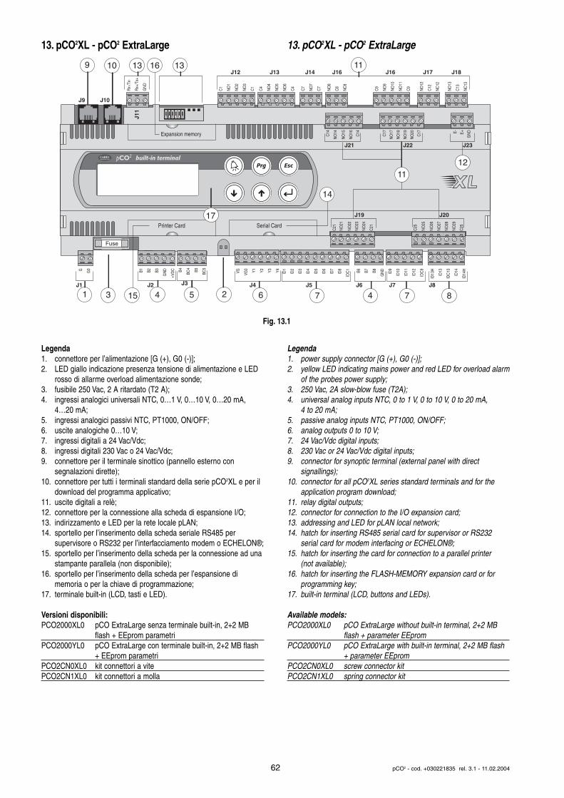
13. pCO2XL - pCO2 ExtraLarge
Legenda1. connettore per l’alimentazione [G (+), G0 (-)];2. LED giallo indicazione presenza tensione di alimentazione e LED
rosso di allarme overload alimentazione sonde;3. fusibile 250 Vac, 2 A ritardato (T2 A);4. ingressi analogici universali NTC, 0…1 V, 0…10 V, 0…20 mA,
4…20 mA;5. ingressi analogici passivi NTC, PT1000, ON/OFF;6. uscite analogiche 0…10 V;7. ingressi digitali a 24 Vac/Vdc;8. ingressi digitali 230 Vac o 24 Vac/Vdc;9. connettore per il terminale sinottico (pannello esterno con
segnalazioni dirette);10. connettore per tutti i terminali standard della serie pCO2XL e per il
download del programma applicativo;11. uscite digitali a relè;12. connettore per la connessione alla scheda di espansione I/O;13. indirizzamento e LED per la rete locale pLAN;14. sportello per l’inserimento della scheda seriale RS485 per
supervisore o RS232 per l’interfacciamento modem o ECHELON®;15. sportello per l’inserimento della scheda per la connessione ad una
stampante parallela (non disponibile);16. sportello per l’inserimento della scheda per l’espansione di
memoria o per la chiave di programmazione;17. terminale built-in (LCD, tasti e LED).
Versioni disponibili:PCO2000XL0 pCO ExtraLarge senza terminale built-in, 2+2 MB
flash + EEprom parametriPCO2000YL0 pCO ExtraLarge con terminale built-in, 2+2 MB flash
+ EEprom parametriPCO2CN0XL0 kit connettori a vitePCO2CN1XL0 kit connettori a molla
13. pCO2XL - pCO2 ExtraLarge
Legenda1. power supply connector [G (+), G0 (-)];2. yellow LED indicating mains power and red LED for overload alarm
of the probes power supply;3. 250 Vac, 2A slow-blow fuse (T2A);4. universal analog inputs NTC, 0 to 1 V, 0 to 10 V, 0 to 20 mA,
4 to 20 mA;5. passive analog inputs NTC, PT1000, ON/OFF;6. analog outputs 0 to 10 V;7. 24 Vac/Vdc digital inputs;8. 230 Vac or 24 Vac/Vdc digital inputs;9. connector for synoptic terminal (external panel with direct
signallings);10. connector for all pCO2XL series standard terminals and for the
application program download;11. relay digital outputs;12. connector for connection to the I/O expansion card;13. addressing and LED for pLAN local network;14. hatch for inserting RS485 serial card for supervisor or RS232
serial card for modem interfacing or ECHELON®;15. hatch for inserting the card for connection to a parallel printer
(not available);16. hatch for inserting the FLASH-MEMORY expansion card or for
programming key;17. built-in terminal (LCD, buttons and LEDs).
Available models:PCO2000XL0 pCO ExtraLarge without built-in terminal, 2+2 MB
flash + parameter EEpromPCO2000YL0 pCO ExtraLarge with built-in terminal, 2+2 MB flash
+ parameter EEpromPCO2CN0XL0 screw connector kitPCO2CN1XL0 spring connector kit
62 pCO2 - cod. +030221835 rel. 3.1 - 11.02.2004
Fuse
Expansion memory
built-in terminal
Rx-
/Tx-
Rx+
/Tx+
GN
D
C1
NO
1
NO
2
NO
3
C1
C4
NO
4
NO
5
NO
6
C4
C7
NO
7
C7
NO
8
C8
NC
8
NO
12
C12
NC
12
NO
13
C13
NC
13
C9
NO
9
NO
10
NO
11
C9
G G0 B1 B2 B3
GN
D
+VD
C B4
BC4 B5
BC5
VG VG0 Y1 Y2 Y3 Y4 ID1
ID2
ID3
ID4
ID5
ID6
ID7
ID8
IDC
1 B6 B7 B8
GN
D
ID9
ID10
ID11
ID12
IDC
9
ID13
H
ID13
IDC
13
ID14
ID14
H
J8J7J6J5J4J3J2J1
J11
J9
J12 J13 J14 J16 J16 J17 J18
J10
1
9 10 13 1316
3 7 7 84 465
J21
J19 J20
J22 J23
215
Printer Card Serial Card
1211
11
14
17
NO
24
NO
23
C21
NO
22
C25
NO
21
NO
29
C21
NO
28
NO
27
NO
26
NO
25
C25
C14
C17
GN
D
NO
16
NO
20 E+
NO
15
NO
19
NO
14
NO
18
C14
NO
17 E-
C17
Fig. 13.1
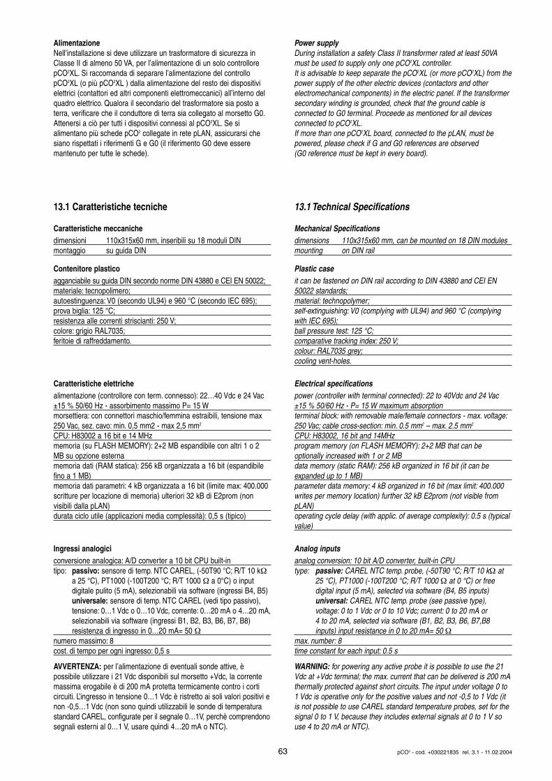
AlimentazioneNell’installazione si deve utilizzare un trasformatore di sicurezza inClasse II di almeno 50 VA, per l’alimentazione di un solo controllorepCO2XL. Si raccomanda di separare l’alimentazione del controllopCO2XL (o più pCO2XL ) dalla alimentazione del resto dei dispositivielettrici (contattori ed altri componenti elettromeccanici) all’interno delquadro elettrico. Qualora il secondario del trasformatore sia posto aterra, verificare che il conduttore di terra sia collegato al morsetto G0.Attenersi a ciò per tutti i dispositivi connessi al pCO2XL. Se si alimentano più schede pCO2 collegate in rete pLAN, assicurarsi chesiano rispettati i riferimenti G e G0 (il riferimento G0 deve essere mantenuto per tutte le schede).
13.1 Caratteristiche tecniche
Caratteristiche meccanichedimensioni 110x315x60 mm, inseribili su 18 moduli DINmontaggio su guida DIN
Contenitore plasticoagganciabile su guida DIN secondo norme DIN 43880 e CEI EN 50022;materiale: tecnopolimero;autoestinguenza: V0 (secondo UL94) e 960 °C (secondo IEC 695);prova biglia: 125 °C;resistenza alle correnti striscianti: 250 V;colore: grigio RAL7035;feritoie di raffreddamento.
Caratteristiche elettrichealimentazione (controllore con term. connesso): 22…40 Vdc e 24 Vac±15 % 50/60 Hz - assorbimento massimo P= 15 Wmorsettiera: con connettori maschio/femmina estraibili, tensione max250 Vac, sez. cavo: min. 0,5 mm2 - max 2,5 mm2
CPU: H83002 a 16 bit e 14 MHzmemoria (su FLASH MEMORY): 2+2 MB espandibile con altri 1 o 2MB su opzione esternamemoria dati (RAM statica): 256 kB organizzata a 16 bit (espandibilefino a 1 MB)memoria dati parametri: 4 kB organizzata a 16 bit (limite max: 400.000scritture per locazione di memoria) ulteriori 32 kB di E2prom (non visibili dalla pLAN)durata ciclo utile (applicazioni media complessità): 0,5 s (tipico)
Ingressi analogiciconversione analogica: A/D converter a 10 bit CPU built-intipo: passivo: sensore di temp. NTC CAREL, (-50T90 °C; R/T 10 kΩ
a 25 °C), PT1000 (-100T200 °C; R/T 1000 Ω a 0°C) o input digitale pulito (5 mA), selezionabili via software (ingressi B4, B5)universale: sensore di temp. NTC CAREL (vedi tipo passivo), tensione: 0…1 Vdc o 0…10 Vdc, corrente: 0…20 mA o 4…20 mA,selezionabili via software (ingressi B1, B2, B3, B6, B7, B8) resistenza di ingresso in 0…20 mA= 50 Ω
numero massimo: 8cost. di tempo per ogni ingresso: 0,5 s
AVVERTENZA: per l’alimentazione di eventuali sonde attive, è possibile utilizzare i 21 Vdc disponibili sul morsetto +Vdc, la corrente massima erogabile è di 200 mA protetta termicamente contro i corti circuiti. L’ingresso in tensione 0…1 Vdc è ristretto ai soli valori positivi enon -0,5…1 Vdc (non sono quindi utilizzabili le sonde di temperaturastandard CAREL, configurate per il segnale 0…1V, perchè comprendonosegnali esterni al 0…1 V, usare quindi 4…20 mA o NTC).
Power supplyDuring installation a safety Class II transformer rated at least 50VAmust be used to supply only one pCO2XL controller.It is advisable to keep separate the pCO2XL (or more pCO2XL) from thepower supply of the other electric devices (contactors and other electromechanical components) in the electric panel. If the transformersecondary winding is grounded, check that the ground cable is connected to G0 terminal. Proceede as mentioned for all devices connected to pCO2XL.If more than one pCO2XL board, connected to the pLAN, must be powered, please check if G and G0 references are observed (G0 reference must be kept in every board).
13.1 Technical Specifications
Mechanical Specificationsdimensions 110x315x60 mm, can be mounted on 18 DIN modulesmounting on DIN rail
Plastic caseit can be fastened on DIN rail according to DIN 43880 and CEI EN50022 standards;material: technopolymer;self-extinguishing: V0 (complying with UL94) and 960 °C (complyingwith IEC 695);ball pressure test: 125 °C;comparative tracking index: 250 V;colour: RAL7035 grey;cooling vent-holes.
Electrical specificationspower (controller with terminal connected): 22 to 40Vdc and 24 Vac±15 % 50/60 Hz - P= 15 W maximum absorptionterminal block: with removable male/female connectors - max. voltage:250 Vac; cable cross-section: min. 0.5 mm2 – max. 2.5 mm2
CPU: H83002, 16 bit and 14MHzprogram memory (on FLASH MEMORY): 2+2 MB that can be optionally increased with 1 or 2 MBdata memory (static RAM): 256 kB organized in 16 bit (it can be expanded up to 1 MB)parameter data memory: 4 kB organized in 16 bit (max limit: 400.000writes per memory location) further 32 kB E2prom (not visible frompLAN)operating cycle delay (with applic. of average complexity): 0.5 s (typicalvalue)
Analog inputsanalog conversion: 10 bit A/D converter, built-in CPUtype: passive: CAREL NTC temp. probe, (-50T90 °C; R/T 10 kΩ at
25 °C), PT1000 (-100T200 °C; R/T 1000 Ω at 0 °C) or free digital input (5 mA), selected via software (B4, B5 inputs)universal: CAREL NTC temp. probe (see passive type), voltage: 0 to 1 Vdc or 0 to 10 Vdc; current: 0 to 20 mA or 4 to 20 mA, selected via software (B1, B2, B3, B6, B7,B8 inputs) input resistance in 0 to 20 mA= 50 Ω
max. number: 8time constant for each input: 0.5 s
WARNING: for powering any active probe it is possible to use the 21Vdc at +Vdc terminal; the max. current that can be delivered is 200 mAthermally protected against short circuits. The input under voltage 0 to1 Vdc is operative only for the positive values and not -0,5 to 1 Vdc (itis not possible to use CAREL standard temperature probes, set for thesignal 0 to 1 V, because they includes external signals at 0 to 1 V souse 4 to 20 mA or NTC).
63 pCO2 - cod. +030221835 rel. 3.1 - 11.02.2004
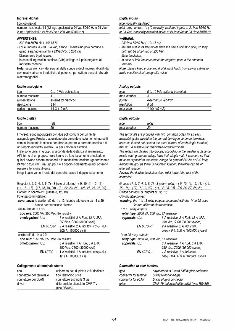
Ingressi digitalitipo: optoisolatinumero max. totale: 14 (12 ingr. optoisolati a 24 Vac 50/60 Hz o 24 Vdc;2 ingr. optoisolati a 24 Vac/Vdc o 230 Vac 50/60 Hz)
AVVERTENZE:- 230 Vac 50/60 Hz (+10/-15 %)- i due ingressi a 230…24 Vac, hanno il medesimo polo comune e
quindi saranno entrambi a 24Vac/Vdc o 230 Vac.L’isolamento è principale.
- in caso di ingressi in continua (Vdc) collegare il polo negativo al morsetto comune.
Nota: separare i cavi dei segnali delle sonde e degli ingressi digitali daicavi relativi ai carichi induttivi e di potenza, per evitare possibili disturbielettromagnetici.
Uscite analogichetipo 0…10 Vdc optoisolatenumero massimo 4alimentazione esterna 24 Vac/Vdcrisoluzione 8 bitcarico massimo 1 kΩ (10 mA)
Uscite digitalitipo relènumero massimo 29
I morsetti sono raggruppati con due poli comuni per un facile assemblaggio. Prestare attenzione alla corrente circolante nei morsetti comuni in quanto la stessa non deve superare la corrente nominale diun singolo morsetto, ovvero 8 A per i morsetti estraibili.I relè sono divisi in gruppi, a seconda della distanza di isolamento.All’interno di un gruppo, i relè hanno tra loro isolamento principale equindi devono essere sottoposti alla medesima tensione (generalmente24 Vac o 230 Vac). Tra i gruppi c’è il doppio isolamento quindi possonoessere a tensione diversa.In ogni caso verso il resto del controllo, esiste il doppio isolamento.
Gruppi: (1, 2, 3, 4, 5, 6, 7) - 8 (relè di allarme) -( 9, 10, 11, 12, 13) -(14, 15 - 16) - (17, 18, 19, 20) - (21, 22, 23, 24) - (25, 26, 27, 28, 29)Contatti in scambio: 3 (uscite 8, 12, 13)Potenza commutabile:avvertenza: le uscite relè da 1 a 13 rispetto alle uscite da 14 a 29
hanno caratteristiche diverseuscite relè da 1 a 13:
tipo relè: 2000 VA, 250 Vac, 8A resistiviomologazioni: UL: 8 A resistivi, 2 A FLA, 12 A LRA,
250 Vac, C300 (30000 cicli) EN 60730-1: 2 A resistivi, 2 A induttivi, cosϕ= 0,4,
2(2) A (100000 cicli)uscite relè da 14 a 29:
tipo relè: 1250 VA, 250 Vac, 5A resistiviomologazioni: UL: 3 A resistivi, 1 A FLA, 6 A LRA,
250 Vac, C300 (30000 cicli)EN 60730-1: 1 A resistivi, 1 A induttivi, cosϕ= 0,4,
1(1) A (100000 cicli)
Collegamento al terminale utentetipo asincrono half duplex a 2 fili dedicatoconnettore per terminale tipo telefonico 6 vieconnettore per pLAN connettore estraibile 3 viedriver differenziale bilanciato CMR 7 V
(tipo RS485)
Digital inputstype: optically insulatedtotal max. number: 14 (12 optically insulated inputs at 24 Vac 50/60 Hzor 24 Vdc; 2 optically insulated inputs at 24 Vac/Vdc or 230 Vac 50/60 Hz
WARNING:- 230 Vac 50/60 Hz (+10/-15 %)- the two 230 to 24 Vac inputs have the same common pole, so they
both will be at 24 Vac or 230 VacMain insulation.
- in case of Vdc inputs connect the negative pole to the common terminal.
Note: please keep probe and digital input leads from power cables toavoid possible electromagnetic noise.
Analog outputstype 0 to 10 Vdc optically insulatedmax. number 4power external 24 Vac/Vdcresolution 8 bitmax. load 1 kΩ (10 mA)
Digital outputstype relaymax. number 29
The terminals are grouped with two common poles for an easy assembling. Be careful to the current flowing in common terminals, because it must not exceed the rated current of each single terminal,that is: 8 A resistive for removable-screw terminals.The relays are divided into groups, according to the insulating distance.Inside each group the relays have their single main insulation, so theymust be exposed to the same voltage (in general 24 Vac or 230 Vac).Among the groups there is double-insulation, therefore can be of different voltage.Anyway the double-insulation does exist toward the rest of the controller.
Groups: (1, 2, 3, 4, 5, 6, 7) - 8 (alarm relay) - ( 9, 10, 11, 12, 13) - (14,15 - 16) - (17, 18, 19, 20) - (21, 22, 23, 24) - (25, 26, 27, 28, 29)Switch contacts: 3 (outputs 8, 12, 13)Commutable power:warning: the 1 to 13 relay outputs compared with the 14 to 29 ones
feature different characteristics1 to 13 relay outputs
relay type: 2000 VA, 250 Vac, 8A resistiveapprovals: UL: 8 A resistive, 2 A FLA, 12 A LRA,
250 Vac, C300 (30,000 cycles)EN 60730-1: 2 A resistive, 2 A inductive,
cosϕ= 0.4, 2(2) A (100,000 cycles)14 to 29 relay outputs
relay type: 1250 VA, 250 Vac, 5A resistiveapprovals: UL: 3 A resistive, 1 A FLA, 6 A LRA,
250 Vac, C300 (30,000 cycles)EN 60730-1: 1 A resistive, 1 A inductive,
cosϕ= 0.4, 1(1) A (100,000 cycles
Connection to user terminaltype asynchronous 2-lead half duplex dedicatedconnector for teminal 6-way telephone-typeconnector for pLAN 3-way plug-in connectordriver CMR 7V balanced differential (type RS485)
64 pCO2 - cod. +030221835 rel. 3.1 - 11.02.2004

Le distanze massime ammesse tra terminale e scheda base (oppuretra i due dispositivi più lontani connessi in pLAN) sono quelle riportatenella seguenta tabella:
con cavo telefonico con cavo schermato AWG24resistenza del distanza resistenza del distanza
cavo (Ω/m) massima (m) cavo (Ω/m) massima (m)≤ 0,14 600 ≤ 0,078 600≤ 0,25 400
Altre caratteristichecondizioni di immagazzinamento: -20T70 °C, 90% UR non condensantecondizioni di funzionamento: -10T60 °C, 90% UR non condensantegrado di protezione: IP20, IP40 nel solo frontalino inquinamento ambientale: normaleclasse secondo la protezione contro le scosse elettriche: da integraresu apparecchiature di Classe I e/o IIPTI dei materiali per isolamento: 250 Vperiodo delle sollecitazioni elettriche delle parti isolanti : lungotipo azioni: 1Ctipo disconnessione o microinterruzione: microinterruzionecategoria di resistenza al calore e al fuoco: categoria D (UL94 - V0)immunità contro le sovratensioni: categoria 1caratteristiche di invecchiamento (ore di funzionamento): 80.000n. cicli di manovra operazioni automatiche: 100.000 (EN 60730-1);30.000 (UL 873)classe e struttura del software: Classe AIl dispositivo non è destinato ad essere tenuto in mano
Nel rispetto dei limiti imposti dalle Normative di sicurezza sulla compatibilità elettromagnetica richiamate nella dichiarazione di conformità (vedi manuale di installazione), gli unici e sporadici malfunzionamenti riscontrati riguardano le indicazioni del display e deiLED. Display e LED si autoripristinano al cessare del disturbo.
Avvertenza: per applicazioni soggette a forte vibrazioni (1,5 mm pk-pk10/55 Hz) si consiglia di fissare tramite fascette i cavi collegati alpCO2XL a circa 3 cm di distanza dai connettori.
13.2 Dimensioni
Max. allowable terminal unit-main board distances (or between the twomost far devices connected in pLAN) are listed below:
with telephone-type cable with AWG24 shielded cablecable max cable max
resistance distance (m) resistance distance (m)(Ω/m) (Ω/m)≤ 0.14 600 ≤ 0.078 600≤ 0.25 400
Other specificationsstorage conditions: -20T70 °C, 90% r.H. non-condensingoperating conditions: -10T60 °C, 90% r.H. non-condensingindex of protection: IP20, IP40 (front panel only)environmental pollution: normalclassification according to protection against electric shock: should beintegrated into Class 1 and/or 2 devicesPTI of insulating materials: 250Vperiod of electric stress across insulating parts: longtype of actions: 1Ctype of disconnection or microinterruption: microinterruptioncategory of resistance to heat and fire: D (UL94 - V0)immunity against voltage surges: category 1ageing period (operating hours): 80,000no. of automatic operating cycles (e.g.: relay): 100,000 (EN 60730-1);30,000 (UL873)software Class and structure: Class ADevice is not intended to be and hand-held
According to the limits quoted on the Safety Standards relevant to electromagnetic compatibility (see conformity declaration published onthe installation manual), rare malfunctioning is founded only on displayand LED indications. LEDs and display are restored when the disturbends.
Warning: for applications subject to strong vibrations (1,5 mm pk-pk10/55 Hz), we suggest you to fasten, through fastening clamps, thecables connected to the pCO2XL at about 3 cm of distance from the connectrors.
13.2 Dimensions
65 pCO2 - cod. +030221835 rel. 3.1 - 11.02.2004
60
110
315
45
44
Fuse
built-in terminal
Fig. 13.2.1
Errata corrige e aggiunte in questa versione delmanuale
• pag. 23: la potenza massima assorbita dal pCO2 è 15 W e non 20 W;• pag. 25: corrette le tabelle 4.4.1.1 e 4.4.2.1 in inglese;• pag. 33: precisazione sul numero di terminali utenti collegabili al
pCO2;• pag. 38: modificate le figure 5.4.1 e 5.4.3, la calza del connettore
pLAN va collegata ad un solo pCO2;• pag. 39: revisione delle avvertenze importanti;• pag. 48: corretto schema generale dei collegamenti elettrici;• pag. 50/51: l’assorbimento deve essere espresso in W e non in Ω;• pag. 59: il capitolo 13 diventa capitolo 12;• pag. 62: aggiunto il capitolo 13 (pCO2XL);
CAREL si riserva la possibilità di apportare modifiche o cambiamenti aipropri prodotti senza alcun preavviso.
Errata corrige and additions to this manual version
• pg 23: the maximum pCO2 power consumption is 15 W not 20 W;• pg 25: tables 4.4.1.1 and 4.4.2.1 have been corrected in English;• pg 33: more precise information on the number of user terminals that
can be connected to the pCO2;• pg 38: figures 5.4.1 and 5.4.3 have been modified, the shield of the
pLAN connector has to be connected to only one pCO2;• pg 39: revision of the important warnings section;• pg 48: general diagram of the electrical connections corrected;• pg 50/51: power consumption must be expressed in W not in Ω;• pg 59: chapter 13 becomes chapter 12;• pg 62: addition of chapter 13 (pCO2XL);
CAREL reserves the right to alter the features of its products withoutprior notice.
66 pCO2 - cod. +030221835 rel. 3.1 - 11.02.2004


Cod
. +
0302
2183
5 r
el.
3.1
- 11
.02.
2004
Agenzia / Agency:
CAREL S.p.A.Via dell’Industria, 11 - 35020 Brugine - Padova (Italy)Tel. (+39) 049.9716611 - Fax (+39) 049.9716600e-mail: [email protected] - www.carel.com