Embed Size (px)
Citation preview

TB 9-2350-277-40&P-2
HEADQUARTERS, DEPARTMENT OF THE ARMY
JUNE 2009
TECHNICAL BULLETIN
INSTALLATION OF CREW II MODIFICATION KIT
19207 – 12498026 FOR
CARRIER, PERSONNEL, FULL TRACKED, ARMORED M113A3
2350-01-219-7577 (EIC AEY)
DISTRIBUTION STATEMENT A: Approved for public release; distribution is unlimited.

TB 9-2350-277-40&P-2
a
WARNING SUMMARY
WARNING SUMMARY
This list summarizes critical WARNINGs in this bulletin. They are repeated here to let you know how important they are. Study these WARNINGs carefully; they can save your life and the lives of personnel you work with.
LIST OF WARNINGS IN WP PROCEDURES
This list includes all WARNINGs in the bulletin. These WARNINGs must be studied carefully and obeyed. They can save your life and the lives of soldiers with whom you work. Failure to obey a warning could cause death or injury as well as destruction of, or damage to, the vehicle and/or equipment.
WARNING
Flammable or explosive compounds can ignite and seriously injure or kill personnel. Remove and stow all flammable and explosive materials from vehicle and surrounding area.
WARNING
Metal chips and grinding dust can cause eye injury. Wear goggles and gloves.
TB 9-2350-277-40&P-2
b
WARNING SUMMARY – Continued
WARNING
Adhesive, primer, sealant compounds, and isopropyl alcohol are toxic and flammable. These compounds are toxic to eyes, skin, and respiratory tract. Continued exposure can make you dizzy and irritate your eyes and throat.
Always use in well ventilated areas, away from heat, sparks, and flames. Do not breathe fumes. Do not allow into contact with skin and eyes. Use goggles or face shield and protective gloves.
FIRST AID
For first aid information, see FM 4-25.11.
TB 9-2350-277-40&P-2
INSERT LATEST UPDATED PAGES/WORK PACKAGES. DESTROY SUPERSEDED DATA.
A/B blank
LIST OF EFFECTIVE PAGES/WORK PACKAGES
Note: The portion of text affected by the changes is indicated by a vertical line in the outer margins of the page. Changes to illustrations are indicated by miniature pointing hands.
Dates of issue for original and changed pages/work packages are:
Original ..................... 30 June 2009
TOTAL NUMBER OF PAGES FOR FRONT AND REAR MATTER IS 26 AND TOTAL NUMBER OF WORK PACKAGES IS 15 CONSISTING OF THE FOLLOWING:
Page/WP *Change No. No.
Page/WP *Change No. No.
Page/WP *Change No. No.
Front Cover 0 a/b 0 A/B blank 0 i – v/vi blank 0 Chapter 1 Index 0 WP 0001 00 – 0002 00 0 Chapter 2 Index 0 WP 0003 00 – 0006 00 0 Chapter 3 Index 0 WP 0007 00 – WP 0010 00 0 Chapter 4 Index 0 WP 0011 00 – WP 0015 00 0 Index-1 – Index-2 0 DA 2028 Sample/Reverse 0 DA 2028/Reverse (3) 0 Authentication 0 Metric Chart 0 Back Cover 0
*Zero in the column indicates an original page or work package.


TB 9-2350-277-40&P-2
i
HEADQUARTERS DEPARTMENT OF THE ARMY
WASHINGTON, D.C., 30 JUNE 2009
TECHNICAL BULLETIN
INSTALLATION OF CREW II MODIFICATION KIT
19207 – 12498026
FOR
CARRIER, PERSONNEL, FULL TRACKED, ARMORED M113A3
2350-01-219-7577 (EIC AEY)
REPORTING ERRORS AND RECOMMENDING IMPROVEMENTS You can help improve this publication. If you find any errors, or if you would like to recommend any improvements to the procedures in this publication, please let us know. The preferred method is to submit your DA Form 2028 (Recommended Changes to Publications and Blank Forms) through the Internet, on the Army Electronic Product Support (AEPS) website. The Internet address is https://aeps.ria.army.mil.The DA Form 2028 is located under the Public Applications section in the AEPS Public Home Page. Fill out the form and click on SUBMIT. Using this form on the AEPS will enable us to respond quicker to your comments and better manage the DA Form 2028 program. You may also mail, e-mail, or fax your comments or DA Form 2028 directly to the U.S. Army TACOM Life Cycle Management Command. The postal mail address is U.S. Army TACOM Life Cycle Management Command, ATTN: AMSTA-LC-LMPP / TECH PUBS, 1 Rock Island Arsenal, Rock Island, IL 61299-7630. The e-mail address is [email protected]. The fax number is DSN 793-0726 or Commercial (309) 782-0726.
DISTRIBUTION STATEMENT A: Approved for public release; distribution is unlimited.

TB 9-2350-277-40&P-2
ii
TABLE OF CONTENTS WP Sequence No.
Page No.
WARNING SUMMARY
CHAPTER 1 – GENERAL INFORMATION
Introduction ..................................................................................................................... 0001 00 Table 1. Kit List ..................................................................................0001 00-2 Table 2. Retained Parts .....................................................................0001 00-2Table 3. Excess Parts to be Discarded..............................................0001 00-3
Equipment Description ................................................................................................... 0002 00Figure 1. CREW II Hardware .............................................................0002 00-2Figure 2. Location of CREW II Components......................................0002 00-4
CHAPTER 2 – MAINTENANCE INSTRUCTIONS
Removal Procedures ...................................................................................................... 0003 00Figure 1. Power Plant Upper Rear Access Panel Removal ..............0003 00-1 Figure 2. Engine Bulkhead Hardware Removal ................................0003 00-2 Figure 3. Commander’s Intercom Unit Removal................................0003 00-3 Figure 4. Spall Liner Right Angle Bracket Hardware Removal..........0003 00-4
Rework Procedures ........................................................................................................ 0004 00Figure 1. Disassemble Power Plant Upper Rear Acces Panel..........0004 00-1 Figure 2. Assemble Power Plant Upper Rear Access Panel.............0004 00-2
Modification Procedures ................................................................................................. 0005 00Figure 1. Locate and Mark CREW II GPS Antenna
Riser Cable Port .................................................................0005 00-2 Figure 2. Location for CREW II GPS Antenna Riser .........................0005 00-3 Figure 3. Location for CREW II Primary Unit Mounting Bracket........0005 00-4 Figure 4. CREW II Primary Unit Clearance Provision .......................0005 00-5 Figure 5. Location for CREW II Engine Bulkhead Cable Clamp........0005 00-6 Figure 6. Location for CREW II Hull Roof Cable Clamp ....................0005 00-7
Installation Procedures ................................................................................................... 0006 00Figure 1. SINGARS Antenna Removal ..............................................0006 00-2Figure 2. Antenna Cover Removal ....................................................0006 00-3Figure 3. GPS Sensor, Mounting Bracket, and Cable Installation.....0006 00-4 Figure 4. GPS Cable Sealant Application..........................................0006 00-5 Figure 5. SINCGARS Antenna Installation ........................................0006 00-6Figure 6. Antenna Cover Installation .................................................0006 00-7Figure 7. GPS Antenna Riser Installation ..........................................0006 00-8 Figure 8. Power Plant Upper Rear Access Panel Installation ...........0006 00-9 Figure 9. RCU/PDA Bracket Assembly Installation ...........................0006 00-10

TB 9-2350-277-40&P-2
iii
TABLE OF CONTENTS – Continued WP Sequence No.
Page No.
CHAPTER 2 – MAINTENANCE INSTRUCTIONS – Continued
Figure 10. Commander’s Intercom Unit Installation .......................... 0006 00-11 Figure 11. RCU/PDA Cable Clamps Installation ............................... 0006 00-12 Figure 12. Primary Unit Mounting Brackets Installation .................... 0006 00-13Figure 13. GPS Antenna Cable Clamps and Power Harness Clamps
Installation ........................................................................ 0006 00-14 Figure 14. GPS Antenna Cables Installation..................................... 0006 00-15 Figure 15. Power Harness, RCU Cable, RCU to PDA Cable, and
GPS Cable Installation..................................................... 0006 00-17
CHAPTER 3 – REPAIR PARTS AND SPECIAL TOOLS LIST (RPSTL)
Repair Parts and Special Tools List (RPSTL) Introduction.............................................0007 00Crew II Modification Kit - 12498026................................................................................0008 00
Figure 1. CREW II Modification Kit - 12498026 (Sheet 1 of 4) ......... 0008 00-1 Figure 1. CREW II Modification Kit - 12498026 (Sheet 2 of 4) ......... 0008 00-1 Figure 1. CREW II Modification Kit - 12498026 (Sheet 3 of 4) ......... 0008 00-1 Figure 1. CREW II Modification Kit - 12498026 (Sheet 4 of 4) ......... 0008 00-1
National Stock Number Index .........................................................................................0009 00 Part Number Index..........................................................................................................0010 00
CHAPTER 4 – SUPPORTING INFORMATION
References......................................................................................................................0011 00 Common Tools and Supplements and Special Tools/Fixtures List ................................0012 00
Table 1. Tool Identification List.......................................................... 0012 00-2 Fabricated Tools .............................................................................................................0013 00
Figure 1. Magentic Drill Base Plate/Template................................... 0013 00-1 Expendable/Durable Items List .......................................................................................0014 00
Table 1. Expendable/Durable Items List ........................................... 0014 00-1 Replacement Kit Parts ....................................................................................................0015 00
Table 1. M113A3 CREW II Modification Kit - 12498026 ................... 0015 00-1
INDEX ..................................................................................................................................INDEX-1

TB 9-2350-277-40&P-2
iv
HOW TO USE THIS MANUAL
HOW TO USE THIS MANUAL
The safest, easiest, and best way to use and maintain Crew II is to use this bulletin. Learning to use this bulletin is as easy as reading it. Knowing what is in this bulletin and how to use it will save you time. Becoming familiar with the work, procedures, and cautions will help you in your job and reduce your exposure to unnecessary hazards.
WHERE DO YOU START
This bulletin is divided into chapters and front and rear matter. The chapters are further divided into Work Packages (WPs) for ease of use. Go to the area within the manual that covers what you are to do and follow the instructions. Be sure to read and follow the WARNINGs, CAUTIONs, and NOTEs.
HOW THIS BULLETIN IS ORGANIZED
The WARNING SUMMARY section provides safety and first aid information. This section includes a list of the most important warnings extracted from the WPs. All of these warnings cover hazards that could kill or injure personnel.
The TABLE OF CONTENTS lists the WPs in each Chapter.
CHAPTER 1 covers general information.
CHAPTER 2 covers maintenance instructions.
CHAPTER 3 contains repair parts and special tools list information.
CHAPTER 4 contains supporting information, such as lists of references, tools, expendable/durable items, etc.
The INDEX is an alphabetical listing of all the WPs in this manual. Each entry is cross-referenced to the WP number and page number.
The DA FORM 2028 is used to report errors and to recommend improvements for procedures in this bulletin. Three blank DA Form 2028s are in the back of this bulletin.
The back cover includes a METRIC CONVERSION CHART that can be used to convert U.S. customary measurements to their metric equivalents. Measurements in this manual are given in U.S. customary unit with metric units in parentheses.
HOW TO USE THE WORK PACKAGES
Pick a key word and look in the INDEX for this key word. Turn to the WP and page indicated.
How to Read the WP
WPs provide either descriptive/supporting information or detailed procedures for repair.
Pay attention to all WARNINGs, CAUTIONs, and NOTEs. These can appear in all types of procedures. They help you avoid harm to yourself, other personnel, and equipment. They also tell you things you should know about the procedure.
TB 9-2350-277-40&P-2
v/vi blank
HOW TO USE THIS MANUAL (cont) Before you start a procedure, get all the tools, supplies, and personnel you need to do the procedure.These items will be listed in the INITIAL SETUP of the WP.
Start with Step 1 and do each step in the order given. Numbered primary steps tell you WHAT to do.Alpha substeps tell you HOW to do it.
Look at the illustrations. Locators show you where the parts are located. Close-up illustrations show the details you need to do the procedure.
The words END OF WORK PACKAGE will tell you when you have finished the procedure.
DEFINITION OF WP TERMS
WARNINGs, CAUTIONs, and NOTEs
Pay attention to all WARNINGs and CAUTIONs within the WP. Ignoring a WARNING could cause death or injury to yourself or other personnel. Ignoring a CAUTION could cause damage to equipment. NOTEs contain facts to make the procedure easier. WARNINGs, CAUTIONs, and NOTEs always appear just above the step to which they apply.
WARNING
Highlights an essential operating or maintenance procedure, practice, condition, statement, etc., which, if not strictly observed, could result in injury to, long term health hazards for, or death of, personnel.
CAUTION
Highlights an essential operating or maintenance procedure, practice, condition, statement, etc., which, if not stricty observed, could result in damage to or destruction of equipment, or loss of mission effectiveness.
NOTE
Highlights an essential operating or maintenance procedure, condition, or statement.
Helper
Helpers are needed in procedures that require more than one person. A helper may be needed to help lift objects or act as an outside observer.
If a helper is needed to perform a procedure, the INITIAL SETUP will list “Helper (H)” under the PERSONNEL REQUIRED heading.
If a helper assists with a step, the step will include: “Have helper assist.”
If a helper performs the action alone, the step will start with “(H):”.


TB 9-2350-277-40&P-2
CHAPTER 1 GENERAL INFORMATION
WORK PACKAGE INDEX
Title Sequence No.
INTRODUCTION ......................................................................................................................... 0001 00 EQUIPMENT DESCRIPTION...................................................................................................... 0002 00


TB 9-2350-277-40&P-2
INTRODUCTION 0001 00
0001 00-1
PURPOSE
The purpose of this technical bulletin (TB) is to provide instructions and guidance on the method of modifying the M113A3 Armored Personnel Carrier for Crew II. It further provides instruction on the installation of the Crew II modification kit P/N 12498026. The Crew II modification kit provides mounting for the next generation of improvised explosive device (IED) jammers. The modular Crew II “plug and play” design, allows the main line replaceable unit (LRU), FRF105C dual antenna, and the remote control unit (RCU) to be utilized by any Heavy Brigade Combat Team (HBCT) vehicle. The M113A3 location was chosen to provide the least impact on mission requirements, for example the commander’s cupola with .50 cal must rotate 360°; however, care must be taken when operating any weapons towards the right rear as the antenna is fixed in that position.
GENERAL
1. Priority. This bulletin is classified NORMAL.
2. End item(s) to be modified. This TB applies to the M113A3, Armored Personnel Carrier, 2350-01-219-7577, P/N 8750170.
3. Module(s) (components, assemblies, subassemblies, boards, and cards) to be modified. Not applicable.
4. Parts to be modified. Vehicle Hull and Engine Compartment Cover (P/N 12369630) will be reworked.
5. Application.
a. Time compliance schedule. Not applicable.
b. Lowest level of maintenance authorized to apply this modification. The lowest level of maintenance authorized to perform installation described by this TB is Sustainment.
c. Work force and man-hour requirements for application of the modification to a single unit, end item, or system. A mechanic and helper require approximately 4 man-hours to install.
d. Modifications to be applied to or concurrently with the application of this kit. Not applicable.
e. Additional information deemed necessary to assist in the application of this modification. Kit application will be concurrent with other depot overhaul/conversion programs, as applicable.
6. Technical publications affected/changed. The installation will be supported by TM 9-2350-277 series technical manuals with the upcoming Change 6.
TB 9-2350-277-40&P-2
INTRODUCTION – Continued 0001 00
0001 00-2
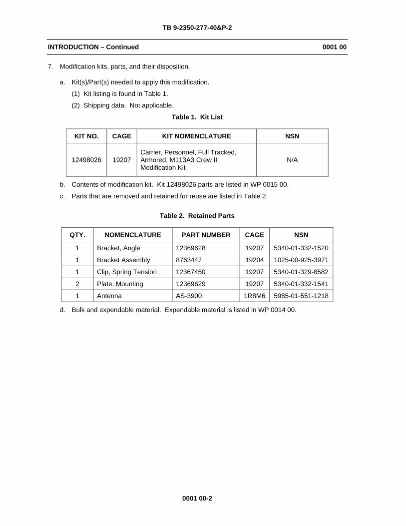
7. Modification kits, parts, and their disposition.
a. Kit(s)/Part(s) needed to apply this modification.
(1) Kit listing is found in Table 1.
(2) Shipping data. Not applicable.
Table 1. Kit List
KIT NO. CAGE KIT NOMENCLATURE NSN
12498026 19207 Carrier, Personnel, Full Tracked, Armored, M113A3 Crew II Modification Kit
N/A
b. Contents of modification kit. Kit 12498026 parts are listed in WP 0015 00.
c. Parts that are removed and retained for reuse are listed in Table 2.
Table 2. Retained Parts
QTY. NOMENCLATURE PART NUMBER CAGE NSN
1 Bracket, Angle 12369628 19207 5340-01-332-1520
1 Bracket Assembly 8763447 19204 1025-00-925-3971
1 Clip, Spring Tension 12367450 19207 5340-01-329-8582
2 Plate, Mounting 12369629 19207 5340-01-332-1541
1 Antenna AS-3900 1R8M6 5985-01-551-1218
d. Bulk and expendable material. Expendable material is listed in WP 0014 00.

TB 9-2350-277-40&P-2
INTRODUCTION – Continued 0001 00
0001 00-3
e. Parts disposition. Parts removed and not reinstalled are considered excess for TB application. Excess parts listed in Table 3 should be discarded IAW AR 725-50 or local salvage regulations.
Table 3. Excess Parts to be Discarded
QTY. NOMENCLATURE PART NUMBER CAGE NSN
4 Screw, Cap, Hexagon H B1821BH025C175N 80204 5305-00-071-2510
4 Nut, Self-Locking, Hex M45913/1-4CG5C 81349 5310-00-088-1251
2 Screw, Cap, Hexagon H B1821BH025C100N 80204 5305-00-225-3843
2 Nut, Self-Locking, Hex MS51922-1 96906 5310-00-088-1251
1 Screw, Cap, Hexagon H B1821BH038C100N 80204 5305-00-068-0510
1 Nut, Self-Locking, Hex M45913/1-6CG5C 81349 5310-00-087-4652
1 Bracket, Angle 12369628 19207 5340-01-332-1520
2 Screw, Cap, Hexagon H B1821BH038C150N 80204 5305-00-725-2317
2 Washer, Flat 10910174-16 19200 5310-00-987-1294
2 Screw, Cap, Hexagon H B1821BH031F100N 80204 5305-00-051-4076
4 Washer, Lock MS45904-72 96906 5310-00-889-2527
2 Nut, Plain Hexagon MS35690-522 96906 5310-00-582-5615
8. Special tools, tool kits, jigs, test, measurement, and diagnostic equipment (TMDE); and fixtures required. Installation requires common hand and power tools (wrenches, drill, etc.) furnished by the maintenance shop/contractor. No special TMDE, jigs, or fixtures are required.
9. Expendable/durable items list. See WP 0014 00.
10. Calibration requirements. No calibration is required.
11. Weight and balance data. Weight and balance are not affected.
12. Facilities. No special facilities are required. No welding is required.
13. Inspection requirements.
a. Prior to kit installation, inspect all mounting provisions for signs of fatigue failure, cracking, and loose or missing attaching hardware. The Crew II kit cannot be installed until certain hull mounting provisions have been completed. See WP 0005 00 for hull preparation procedures.
b. Ensure all kit parts are available prior to installation. See WP 0015 00 for a list of kit parts. Inspect all kit parts for signs of cracking or distortion of the supports and brackets, damaged cables, and missing hardware.
c. After kit installation, ensure all kit components are mounted securely. Inspect the new cables to ensure they are securely clamped and tied to the existing cables and are not going to be pinched or damaged during carrier operation.

TB 9-2350-277-40&P-2
INTRODUCTION – Continued 0001 00
0001 00-4
14. Tools and Equipment.
a. Commonly-used tools and equipment having application to sustainment maintenance, in general, furnished by the maintenance activity/contractor. See WP 0012 00.
b. Special tools: See WP 0012 00.
c. Fabricated tools: See WP 0013 00.
15. Recording and reporting of the installation.
a. Reporting requirements. Refer to AR-750-10/DA Pamphlet 750-8.
b. Marking equipment. Remove existing part number 12369630 and replace with 12498099 on reworked cover, engine compartment.
16. Material change (MC) number. Not applicable.
END OF WORK PACKAGE

TB 9-2350-277-40&P-2
EQUIPMENT DESCRIPTION 0002 00
0002 00-1
TB 9-2350-277-40&P-2
EQUIPMENT DESCRIPTION – Continued 0002 00
0002 00-2
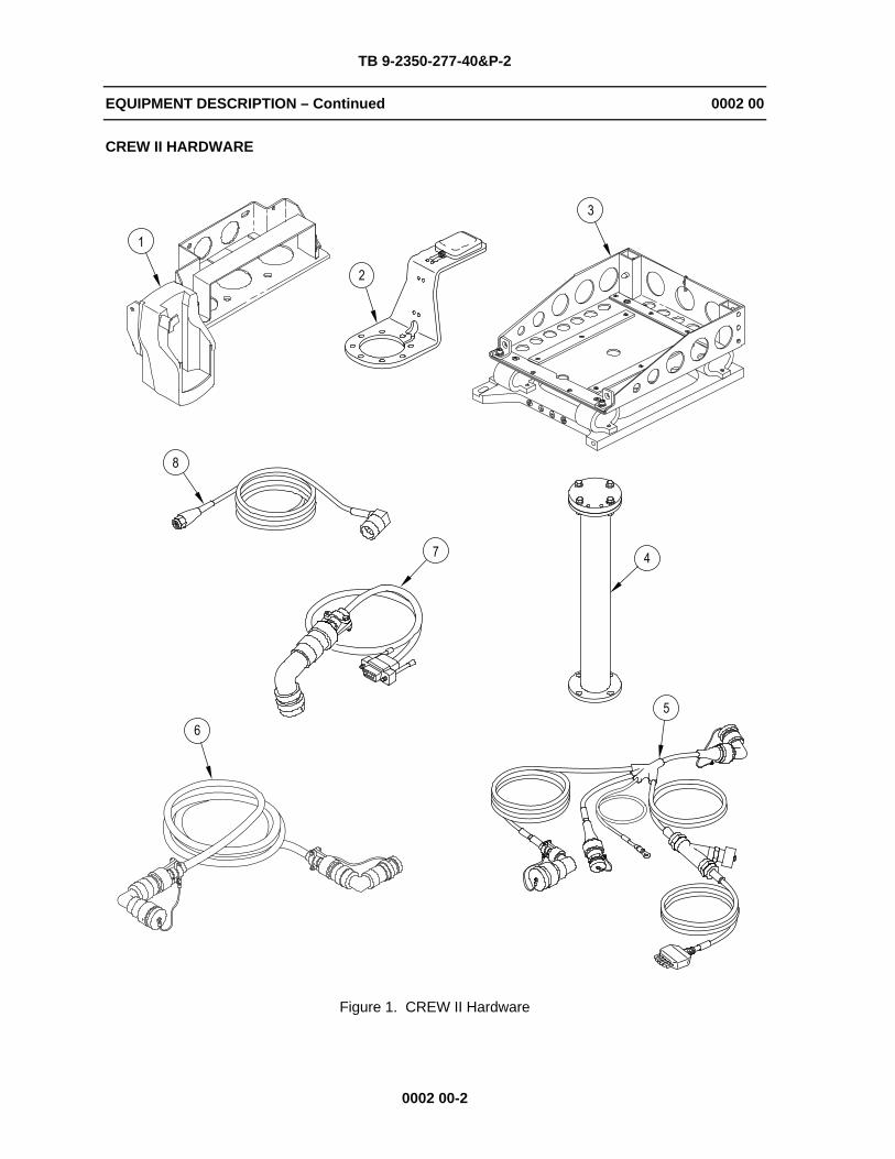
CREW II HARDWARE
Figure 1. CREW II Hardware
TB 9-2350-277-40&P-2
EQUIPMENT DESCRIPTION – Continued 0002 00
0002 00-3
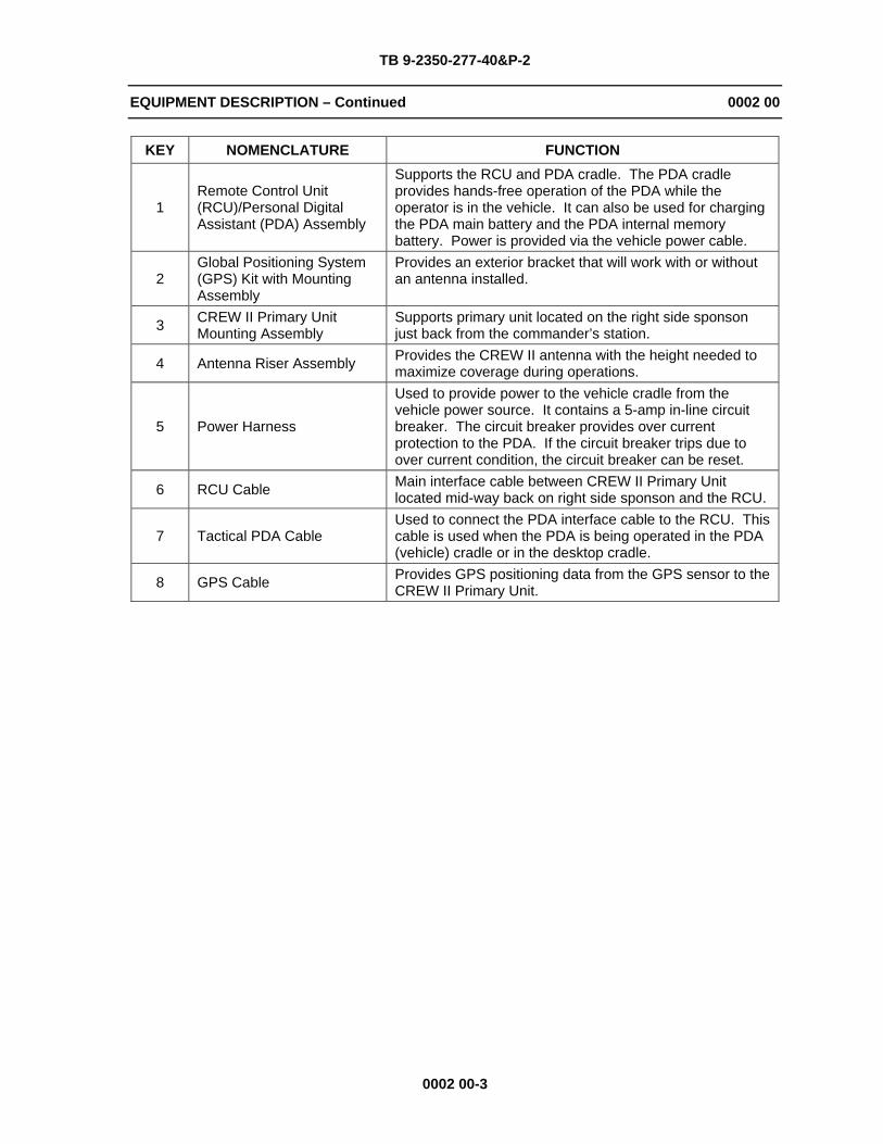
KEY NOMENCLATURE FUNCTION
1Remote Control Unit (RCU)/Personal Digital Assistant (PDA) Assembly
Supports the RCU and PDA cradle. The PDA cradle provides hands-free operation of the PDA while the operator is in the vehicle. It can also be used for charging the PDA main battery and the PDA internal memory battery. Power is provided via the vehicle power cable.
2Global Positioning System (GPS) Kit with Mounting Assembly
Provides an exterior bracket that will work with or without an antenna installed.
3 CREW II Primary Unit Mounting Assembly
Supports primary unit located on the right side sponson just back from the commander’s station.
4 Antenna Riser Assembly Provides the CREW II antenna with the height needed to maximize coverage during operations.
5 Power Harness
Used to provide power to the vehicle cradle from the vehicle power source. It contains a 5-amp in-line circuit breaker. The circuit breaker provides over current protection to the PDA. If the circuit breaker trips due to over current condition, the circuit breaker can be reset.
6 RCU Cable Main interface cable between CREW II Primary Unit located mid-way back on right side sponson and the RCU.
7 Tactical PDA Cable Used to connect the PDA interface cable to the RCU. This cable is used when the PDA is being operated in the PDA (vehicle) cradle or in the desktop cradle.
8 GPS Cable Provides GPS positioning data from the GPS sensor to the CREW II Primary Unit.

TB 9-2350-277-40&P-2
EQUIPMENT DESCRIPTION – Continued 0002 00
0002 00-4
LOCATION OF CREW II MOUNTING COMPONENTS
The primary unit (3) is mounted on the right side sponson just back from the commander’s station. The RCU/PDA cradle and bracket assembly (1) is mounted on the upper right side engine bulkhead with the GPS mounting bracket and antenna (2) located just above on the right front upper hull. The antenna riser (4) is mounted on the right rear upper hull.
Figure 2. Location of CREW II Mounting Components
END OF WORK PACKAGE

TB 9-2350-277-40&P-2
CHAPTER 2 MAINTENANCE INSTRUCTIONS
WORK PACKAGE INDEX
Title Sequence No.
REMOVAL PROCEDURES......................................................................................................... 0003 00 REWORK PROCEDURES .......................................................................................................... 0004 00 MODIFICATION PROCEDURES................................................................................................ 0005 00 INSTALLATION PROCEDURES................................................................................................. 0006 00


TB 9-2350-277-40&P-2
REMOVAL PROCEDURES 0003 00
0003 00-1
THIS WORK PACKAGE COVERS: Remove Power Plant Upper Rear Access Panel (page 0003 00-1). Remove Engine Bulkhead Hardware or Commander’s Intercom Unit (page 0003 00-2). Remove Spall Liner Right Angle Bracket Hardware (page 0003 00-4).
INITIAL SETUP:
Maintenance LevelSustainment
Tools and Special ToolsGeneral Mechanic’s Tool Kit (WP 0012 00, Item 5)
Personnel RequiredMechanic
ReferencesTM 9-2350-277-20
Equipment ConditionsCarrier parked on level ground Engine stopped (TM 9-2350-277-10) Vehicle blocked (TM 9-2350-277-10)
REMOVE POWER PLANT UPPER REAR ACCESS PANEL
1. Loosen four T-bolts (2) and clamps (1) securing power plant upper rear access panel (3) to engine bulkhead. Retain power plant upper rear access panel for re-installation after modification.
Figure 1. Power Plant Upper Rear Access Panel Removal

TB 9-2350-277-40&P-2
REMOVAL PROCEDURES – Continued 0003 00
0003 00-2
REMOVE ENGINE BULKHEAD HARDWARE OR COMMANDER’S INTERCOM UNIT
NOTE
If the carrier has a commander’s intercom unit on the left side of the engine bulkhead, do Step 1. If carrier has a commander’s intercom unit on the right side of the engine bulkhead, do Steps 2-3.
1. Remove two screws (6), lockwashers (5), and self-locking nuts (4). Discard hardware.
Figure 2. Engine Bulkhead Hardware Removal

TB 9-2350-277-40&P-2
REMOVAL PROCEDURES – Continued 0003 00
0003 00-3
2. Disconnect battery ground strap. See TM 9-2350-277-20.
3. Remove commander’s intercom unit from right side of engine bulkhead.
a. Disconnect communication harness (10) from commander’s intercom unit (9).
b. Remove two screws (11), four lockwashers (8), two self-locking nuts (7), and commander’s intercom unit (9) from right side of engine bulkhead. Discard hardware.
Figure 3. Commander’s Intercom Unit Removal
TB 9-2350-277-40&P-2
REMOVAL PROCEDURES – Continued 0003 00
0003 00-4
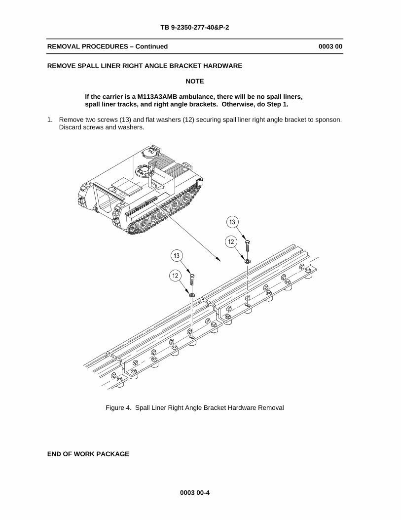
REMOVE SPALL LINER RIGHT ANGLE BRACKET HARDWARE
NOTE
If the carrier is a M113A3AMB ambulance, there will be no spall liners, spall liner tracks, and right angle brackets. Otherwise, do Step 1.
1. Remove two screws (13) and flat washers (12) securing spall liner right angle bracket to sponson. Discard screws and washers.
Figure 4. Spall Liner Right Angle Bracket Hardware Removal
END OF WORK PACKAGE

TB 9-2350-277-40&P-2
REWORK PROCEDURES 0004 00
0004 00-1
THIS WORK PACKAGE COVERS: Disassemble Power Plant Upper Rear Access Panel (page 0004 00-1). Assemble Power Plant Upper Rear Access Panel (page 0004 00-2).
INITIAL SETUP:
Maintenance LevelSustainment
Tools and Special ToolsGeneral Mechanic’s Tool Kit (WP 0012 00, Item 5)
Materials/PartsCrew II Modification Kit (12498026)
Personnel RequiredMechanic
Equipment ConditionsPower plant upper rear access panel
removed (WP 0003 00)
DISASSEMBLE POWER PLANT UPPER REAR ACCESS PANEL
1. Remove screw (4), self-locking nut (8), and spring tension clip (5) from angle bracket (6). Discard screw and nut. Retain spring tension clip for reassembly.
2. Remove two screws (10), self-locking nuts (9), and bracket assembly (11) from angle bracket (6). Discard screws and nuts. Retain bracket assembly for reassembly.
3. Remove four screws (1), self-locking nuts (7), two mounting plates (2), and angle brackets (6) from power plant upper rear access panel (3). Discard screws, nuts, and one angle bracket. Retain mounting plates and one angle bracket for reassembly.
Figure 1. Disassemble Power Plant Upper Rear Access Panel

TB 9-2350-277-40&P-2
REWORK PROCEDURES – Continued 0004 00
0004 00-2
ASSEMBLE POWER PLANT UPPER REAR ACCESS PANEL
1. Install angle bracket (6) in its new orientation rotated 180° on power plant upper rear access panel (3). Secure with two screws (12), mounting plate (2) and two self-locking nuts (14).
2. Install spring tension clip (5) on angle bracket (6). Secure with screw (13) and self-locking nut (15).
3. Install bracket assembly (17) on power plant upper rear access panel (3). Secure with two screws (12), mounting plate (2) and two self-locking nuts (14).
4. Install bracket assembly (11) on bracket assembly (17). Secure with two screws (18) and self-locking nuts (16).
5. Remove existing part number 12369630 and replace with 12498099 on power plant upper rear access panel.
Figure 2. Assemble Power Plant Upper Rear Access Panel
END OF WORK PACKAGE
TB 9-2350-277-40&P-2
MODIFICATION PROCEDURES 0005 00
0005 00-1
THIS WORK PACKAGE COVERS: Drill CREW II GPS Antenna Riser Cable Port (page 0005 00-1). Drill CREW II Primary Unit Mounting Bracket (page 0005 00-4). Clearance for CREW II Primary Unit (page 0005 00-5). Drill CREW II Engine Bulkhead Cable Clamp (page 0005 00-6). Drill CREW II Hull Roof Cable Clamp (page 0005 00-7).
INITIAL SETUP:
Maintenance LevelSustainment
Tools and Special ToolsCutoff Saw, Air Powered (WP 0012, Item 1) Die and Tap Set, Thread Cutting (WP 0012 00, Item 2) Drilling Machine, Upright (WP 0012 00, Item 3) Drill Set, Twist (WP 0012 00, Item 4) General Mechanic’s Tool Kit (WP 0012 00, Item 5) Goggles, Industrial (WP 0012 00, Item 6) Hole Saw Set, Carbide Tipped (WP 0012, Item 7) Magnetic Drill Base Plate/Template (WP 0013 00) Measuring Tape ( WP 0012 00, Item 8) Portable Drill, Electric, 1/2 inch (WP 0012 00), Item 9) Sander, Disk, Electric, Portable (WP 0012, Item 10)
Materials/PartsCREW II Modification Kit (12498026) Wheel, Cutoff (WP 0014 00, Item 3)
Personnel RequiredMechanic
ReferencesTM 43-0139
Equipment ConditionsCarrier parked on level ground Engine stopped (TM 9-2350-277-10) Vehicle blocked (TM 9-2350-277-10)
DRILL CREW II GPS ANTENNA RISER CABLE PORT
WARNING
Flammable or explosive compounds can ignite and seriously injure or kill personnel. Remove and stow all flammable and explosive materials from vehicle and surrounding area.
CAUTION
Remove all equipment and gear from right side sponson area and top right side rear area to prevent damage when drilling holes in right side wall and upper hull.

TB 9-2350-277-40&P-2
MODIFICATION PROCEDURES – Continued 0005 00
0005 00-2
1. Locate and mark for center hole (2), measuring from right hull edge (3) 5 inches and 15-5/32 inches from rear hull edge (1).
Figure 1. Locate and Mark CREW II GPS Antenna Riser Cable Port

TB 9-2350-277-40&P-2
MODIFICATION PROCEDURES – Continued 0005 00
0005 00-3
NOTE
The 3-9/16 inch hole in the magnetic drill base plate/template must align with 3-1/2 inch hole previously marked on hull roof. Minor adjustments to position magnetic drill base plate/template may be necessary.
2. Position magnetic drill base plate/template (4) on hull roof right rear corner. Measure 12-21/32 inches from the rear edge of hull (1). Measure 2-1/2 inches from the right hull edge (5).
NOTE
The magnetic drill base plate/template is 1 inch thick. Marking the drill for a maximum depth of 2-1/4 inches will prevent any break thru.
3. Drill four holes (3) using a 5/16 inch drill to a maximum depth of 1-1/4 inches. DO NOT BREAK THRU.
4. Drill a pilot hole (6) using a 1/4 inch drill bit and magnetic drilling machine.
5. Drill center hole (2) using a 3-1/2 inch saw drill bit and magnetic drilling machine.
6. Tap four holes (3) using a 3/8 x 16 tap. Tap to a minimum of 1 inch depth.
Figure 2. Location for CREW II GPS Antenna Riser
7. Paint drilled area to prevent corrosion. Reference TM 43-0139.

TB 9-2350-277-40&P-2
MODIFICATION PROCEDURES – Continued 0005 00
0005 00-4
DRILL CREW II PRIMARY UNIT MOUNTING BRACKET
NOTE
To protect hull integrity, do not break through hull when drilling. Measure and mark drill for required depth listed in the following steps.
1. Locate and mark two holes (7) on interior of right side hull, measuring from engine bulkhead (5) and from inside of hull roof edge (6).
2. Drill two holes using a 5/16 inch drill to a maximum depth of 1 inch. DO NOT BREAK THRU.
3. Tap two holes using a 3/8 x 16 tap to a minimum of 7/8 inch depth.
Figure 3. Location for CREW II Primary Unit Mounting Bracket
4. Paint drilled area to prevent corrosion. Reference TM 43-0139.
TB 9-2350-277-40&P-2
MODIFICATION PROCEDURES – Continued 0005 00
0005 00-5
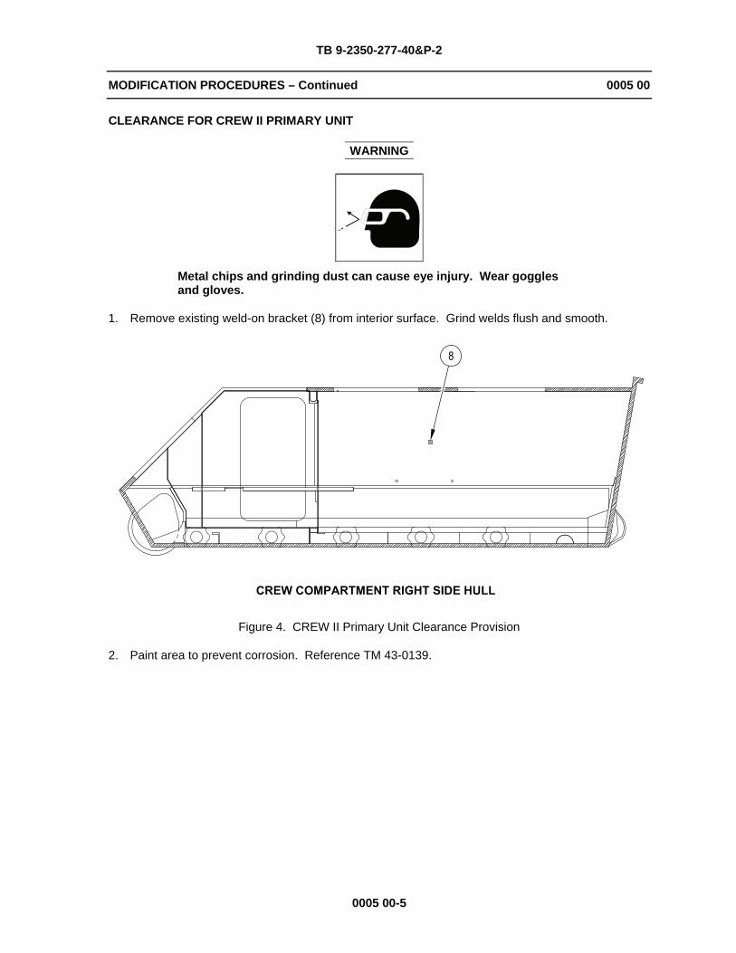
CLEARANCE FOR CREW II PRIMARY UNIT
WARNING
Metal chips and grinding dust can cause eye injury. Wear goggles and gloves.
1. Remove existing weld-on bracket (8) from interior surface. Grind welds flush and smooth.
Figure 4. CREW II Primary Unit Clearance Provision
2. Paint area to prevent corrosion. Reference TM 43-0139.

TB 9-2350-277-40&P-2
MODIFICATION PROCEDURES – Continued 0005 00
0005 00-6
DRILL CREW II ENGINE BULKHEAD CABLE CLAMP
1. Locate and mark for hole (11) on engine bulkhead, measuring from inside of hull roof edge (9) and from inside of right side hull edge (10).
2. Drill a hole using a 1/4 inch drill thru engine bulkhead hull.
Figure 5. Location for CREW II Engine Bulkhead Cable Clamp
TB 9-2350-277-40&P-2
MODIFICATION PROCEDURES – Continued 0005 00
0005 00-7/8 blank
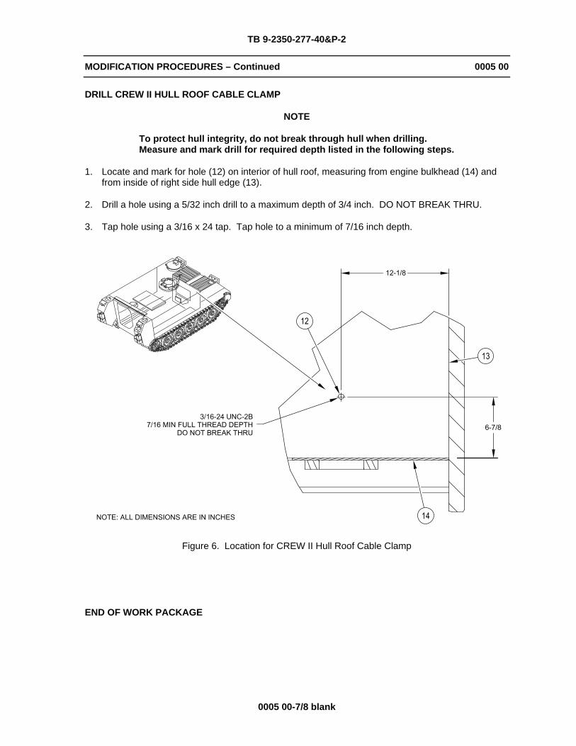
DRILL CREW II HULL ROOF CABLE CLAMP
NOTE
To protect hull integrity, do not break through hull when drilling. Measure and mark drill for required depth listed in the following steps.
1. Locate and mark for hole (12) on interior of hull roof, measuring from engine bulkhead (14) and from inside of right side hull edge (13).
2. Drill a hole using a 5/32 inch drill to a maximum depth of 3/4 inch. DO NOT BREAK THRU.
3. Tap hole using a 3/16 x 24 tap. Tap hole to a minimum of 7/16 inch depth.
Figure 6. Location for CREW II Hull Roof Cable Clamp
END OF WORK PACKAGE

TB 9-2350-277-40&P-2
INSTALLATION PROCEDURES 0006 00
0006 00-1
THIS WORK PACKAGE COVERS: Install GPS Kit (page 0006 00-1). Install GPS Antenna Riser (page 0006 00-8). Install Power Plant Upper Rear Access Panel (page 0006 00-9). Install RCU/PDA Bracket Assembly (page 0006 00-10). Install RCU/PDA Cable Clamps and Commander’s Intercom Unit (page 0006 00-11). Install Primary Unit Bracket Assembly (page 0006 00-13). Install GPS Antenna Cable Clamps and Power Harness Clamps (page 0006 00-14). Install GPS Antenna Cables (page 0006 00-15). Install Power Harness, RCU Cable, RCU to PDA Cable, and GPS Cable (page 0006 00-16).
INITIAL SETUP:
Maintenance LevelSustainment
Tools and Special ToolsGeneral Mechanic’s Tool Kit (WP 0012 00, Item 5) Torque Wrench (WP 0012, Item 11)
Materials/PartsCleaning Compound (WP 0014 00, Item 1) Crew II Modification Kit (12498026)
Personnel RequiredMechanic
Equipment ConditionsCarrier parked on level ground Engine stopped (TM 9-2350-277-10) Vehicle blocked (TM 9-2350-277-10)
INSTALL GPS KIT
NOTE
If the carrier has a SINCGARS antenna mounted, do Steps 1-2. If carrier has no antenna, go to Step 3.

TB 9-2350-277-40&P-2
INSTALLATION PROCEDURES – Continued 0006 00
0006 00-2
1. Remove SINCGARS antenna from vehicle.
a. Remove bolt (6), two lockwashers (5), and ground strap (8) from inside vehicle. Retain hardware for re-installation.
b. Disconnect cable (7) from antenna base (3).
c. Remove four screws (2), lockwashers (1), antenna (3), and gasket (4) from vehicle. Discard screws and gasket. Retain antenna and lockwashers for re-installation.
2. Scrape any remaining gasket material from mating surface. Clean with cleaning compound.
Figure 1. SINCGARS Antenna Removal
TB 9-2350-277-40&P-2
INSTALLATION PROCEDURES – Continued 0006 00
0006 00-3
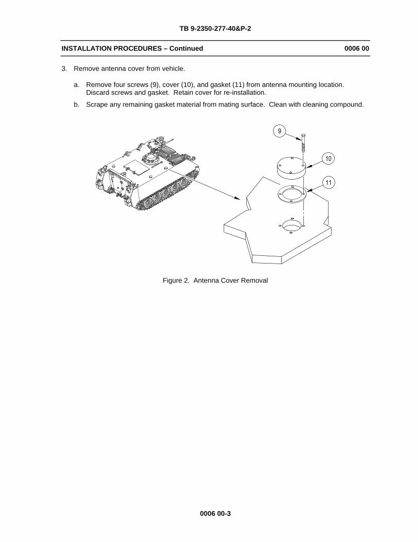
3. Remove antenna cover from vehicle.
a. Remove four screws (9), cover (10), and gasket (11) from antenna mounting location. Discard screws and gasket. Retain cover for re-installation.
b. Scrape any remaining gasket material from mating surface. Clean with cleaning compound.
Figure 2. Antenna Cover Removal

TB 9-2350-277-40&P-2
INSTALLATION PROCEDURES – Continued 0006 00
0006 00-4
4. Install GPS sensor, mounting bracket, and cable on vehicle.
a. Route GPS cable (13) through antenna opening, new gasket (15), and GPS mounting bracket (14).
b. Connect GPS cable (13) to GPS sensor (12).
c. Install GPS sensor (12) on GPS mounting bracket (14) and secure with two screws (17).
d. Secure GPS cable (13) to GPS mounting bracket (14) with three tie straps (16).
e. Position gasket (15) and GPS mounting bracket (14) over antenna opening.
Figure 3. GPS Sensor, Mounting Bracket, and Cable Installation

TB 9-2350-277-40&P-2
INSTALLATION PROCEDURES – Continued 0006 00
0006 00-5
WARNING
Adhesive, primer, sealant compounds, and isopropyl alcohol are toxic and flammable. These compounds are toxic to eyes, skin, and respiratory tract. Continued exposure can make you dizzy and irritate your eyes and throat.
Always use in well ventilated areas, away from heat, sparks, and flames. Do not breathe fumes. Do not allow into contact with skin and eyes. Use goggles or face shield and protective gloves.
5. Apply adhesive over GPS cable (12) to seal out water.
Figure 4. GPS Cable Sealant Application
TB 9-2350-277-40&P-2
INSTALLATION PROCEDURES – Continued 0006 00
0006 00-6
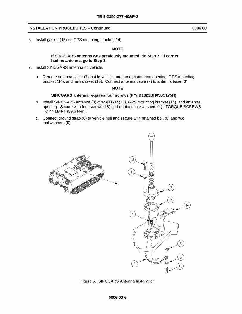
6. Install gasket (15) on GPS mounting bracket (14).
NOTE
If SINCGARS antenna was previously mounted, do Step 7. If carrier had no antenna, go to Step 8.
7. Install SINCGARS antenna on vehicle.
a. Reroute antenna cable (7) inside vehicle and through antenna opening, GPS mounting bracket (14), and new gasket (15). Connect antenna cable (7) to antenna base (3).
NOTE
SINCGARS antenna requires four screws (P/N B1821BH038C175N).
b. Install SINCGARS antenna (3) over gasket (15), GPS mounting bracket (14), and antenna opening. Secure with four screws (18) and retained lockwashers (1). TORQUE SCREWS TO 44 LB-FT (59.6 N·m).
c. Connect ground strap (8) to vehicle hull and secure with retained bolt (6) and two lockwashers (5).
Figure 5. SINCGARS Antenna Installation
TB 9-2350-277-40&P-2
INSTALLATION PROCEDURES – Continued 0006 00
0006 00-7
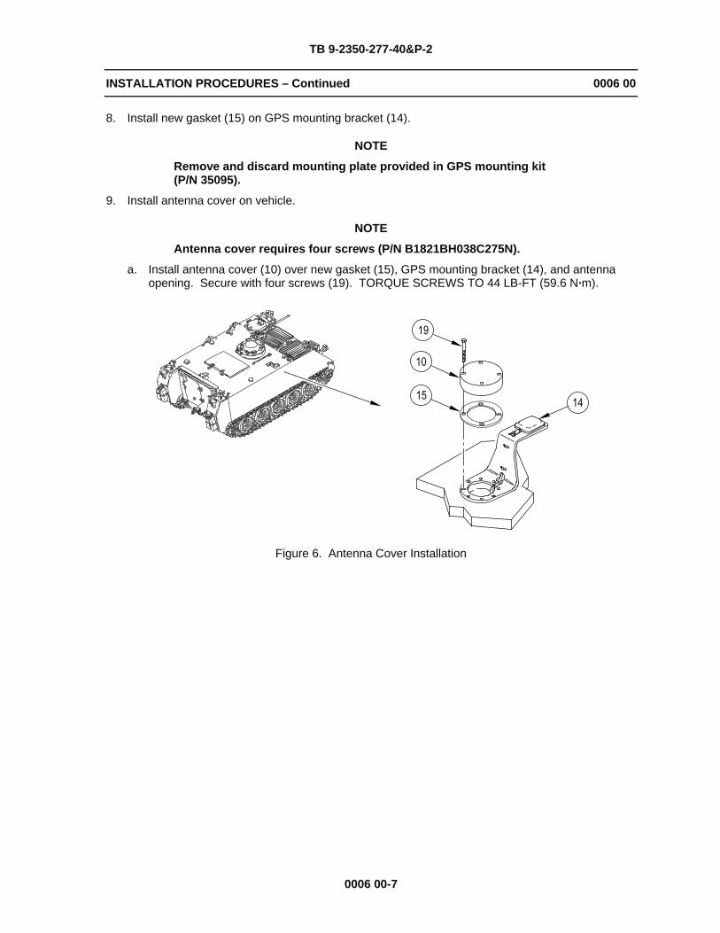
8. Install new gasket (15) on GPS mounting bracket (14).
NOTE
Remove and discard mounting plate provided in GPS mounting kit (P/N 35095).
9. Install antenna cover on vehicle.
NOTE
Antenna cover requires four screws (P/N B1821BH038C275N).
a. Install antenna cover (10) over new gasket (15), GPS mounting bracket (14), and antenna opening. Secure with four screws (19). TORQUE SCREWS TO 44 LB-FT (59.6 N·m).
Figure 6. Antenna Cover Installation

TB 9-2350-277-40&P-2
INSTALLATION PROCEDURES – Continued 0006 00
0006 00-8
INSTALL GPS ANTENNA RISER
1. Clean antenna riser mounting surface on hull with cleaning compound.
2. Install new gasket (15) and antenna riser (24) over GPS antenna opening. Secure with four screws (26) and lockwashers (25). TORQUE SCREWS TO 44 LB-FT (59.6 N·m).
3. Install new gasket (15) and access cover (22) on antenna riser (24). Secure with four screws (18), six flat washers (20), two lockwashers (21), and four self-locking nuts (23).
Figure 7. GPS Antenna Riser Installation

TB 9-2350-277-40&P-2
INSTALLATION PROCEDURES – Continued 0006 00
0006 00-9
INSTALL POWER PLANT UPPER REAR ACCESS PANEL
1. Install power plant upper rear access panel (29) to engine bulkhead. Secure with four clamps (27) and T-bolts (28).
2. Make sure panel seals hull opening to prevent carbon monoxide leaks.
Figure 8. Power Plant Upper Rear Access Panel Installation

TB 9-2350-277-40&P-2
INSTALLATION PROCEDURES – Continued 0006 00
0006 00-10
INSTALL RCU/PDA BRACKET ASSEMBLY
1. Install RCU/PDA bracket assembly (32) to engine bulkhead. Secure with two screws (33), four lockwashers (31), and two self-locking nuts (30).
Figure 9. RCU/PDA Bracket Assembly Installation

TB 9-2350-277-40&P-2
INSTALLATION PROCEDURES – Continued 0006 00
0006 00-11
INSTALL RCU/PDA CABLE CLAMPS AND COMMANDER’S INTERCOM UNIT
NOTE
If the carrier has a commander’s intercom unit on the left side of the engine bulkhead, go to Step 3. If carrier has a commander’s intercom unit on the right side of the engine bulkhead, do Steps 1-2.
1. Install commander’s intercom mounting bracket (39) to RCU/PDA bracket assembly (32). Secure with two screws (34), lockwashers (38), and self-locking nuts (37).
2. Install commander’s intercom unit (35) to mounting bracket (39). Secure with two screws (33) and lockwashers (36). Connect communication harness to commander’s intercom unit (35).
Figure 10. Commander’s Intercom Unit Installation
TB 9-2350-277-40&P-2
INSTALLATION PROCEDURES – Continued 0006 00
0006 00-12
NOTE
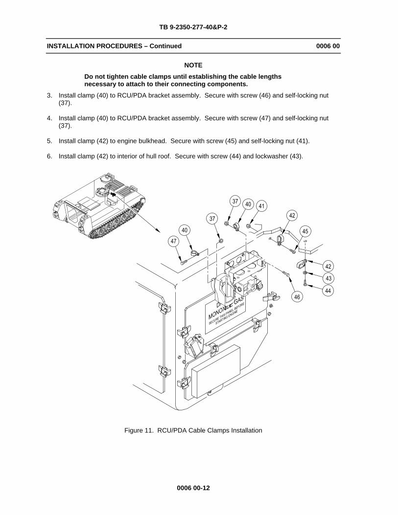
Do not tighten cable clamps until establishing the cable lengths necessary to attach to their connecting components.
3. Install clamp (40) to RCU/PDA bracket assembly. Secure with screw (46) and self-locking nut (37).
4. Install clamp (40) to RCU/PDA bracket assembly. Secure with screw (47) and self-locking nut (37).
5. Install clamp (42) to engine bulkhead. Secure with screw (45) and self-locking nut (41).
6. Install clamp (42) to interior of hull roof. Secure with screw (44) and lockwasher (43).
Figure 11. RCU/PDA Cable Clamps Installation

TB 9-2350-277-40&P-2
INSTALLATION PROCEDURES – Continued 0006 00
0006 00-13
INSTALL PRIMARY UNIT BRACKET ASSEMBLY
NOTE
Do not tighten screws until the mounting assembly is level. Brackets are slotted to help align and keep the mount assembly level.
1. Install two mounting brackets (49) to primary unit mounting bracket assembly (51). Secure with two screws (26), lockwashers (25), and washers (48).
2. Position primary unit mounting bracket assembly (51) on right side sponson.
NOTE
If carrier is a M113A3AMB ambulance, use two screws (50) (P/N B1821BH038C150N). Otherwise, use two screws (50) (P/N B1821BH038C200N).
a. Install two screws (50), lockwashers (25), and flat washers (48) to secure primary unit bracket assembly (51) to right side sponson.
b. Secure forward mounting bracket (49) to right side hull with a screw (26), lockwasher (25), and flat washer (48).
c. Secure rear mounting bracket (49) and ground strap (52) to right side hull with a screw (26), lockwasher (25), and flat washer (48).
3. Level primary unit mounting bracket assembly (51) and tighten four screws (26) and two screws (50). TORQUE SCREWS TO 44 LB-FT (59.6 N·m).
4. Secure ground strap (52) to primary unit bracket assembly (50) with one tie strap (16).
Figure 12. Primary Unit Mounting Brackets Installation
TB 9-2350-277-40&P-2
INSTALLATION PROCEDURES – Continued 0006 00
0006 00-14
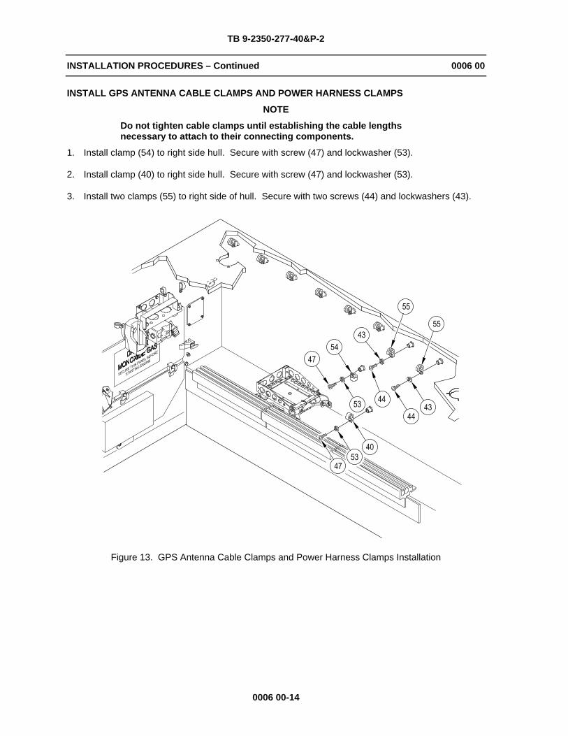
INSTALL GPS ANTENNA CABLE CLAMPS AND POWER HARNESS CLAMPS
NOTE
Do not tighten cable clamps until establishing the cable lengths necessary to attach to their connecting components.
1. Install clamp (54) to right side hull. Secure with screw (47) and lockwasher (53).
2. Install clamp (40) to right side hull. Secure with screw (47) and lockwasher (53).
3. Install two clamps (55) to right side of hull. Secure with two screws (44) and lockwashers (43).
Figure 13. GPS Antenna Cable Clamps and Power Harness Clamps Installation
TB 9-2350-277-40&P-2
INSTALLATION PROCEDURES – Continued 0006 00
0006 00-15
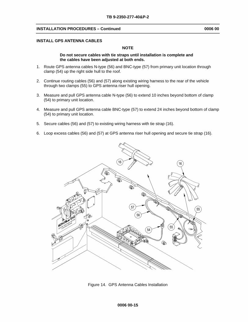
INSTALL GPS ANTENNA CABLES
NOTE
Do not secure cables with tie straps until installation is complete and the cables have been adjusted at both ends.
1. Route GPS antenna cables N-type (56) and BNC-type (57) from primary unit location through clamp (54) up the right side hull to the roof.
2. Continue routing cables (56) and (57) along existing wiring harness to the rear of the vehicle through two clamps (55) to GPS antenna riser hull opening.
3. Measure and pull GPS antenna cable N-type (56) to extend 10 inches beyond bottom of clamp (54) to primary unit location.
4. Measure and pull GPS antenna cable BNC-type (57) to extend 24 inches beyond bottom of clamp (54) to primary unit location.
5. Secure cables (56) and (57) to existing wiring harness with tie strap (16).
6. Loop excess cables (56) and (57) at GPS antenna riser hull opening and secure tie strap (16).
Figure 14. GPS Antenna Cables Installation
TB 9-2350-277-40&P-2
INSTALLATION PROCEDURES – Continued 0006 00
0006 00-16
INSTALL POWER HARNESS, RCU CABLE, RCU TO PDA CABLE, AND GPS CABLE
NOTE
Do not secure cables with tie straps until installation is complete and the cables have been adjusted at both ends.
1. Route GPS cable (13) from hull opening along existing wiring harness to rear of vehicle and down through clamp (54) to primary unit location.
2. Route power harness (58) and RCU cable (59) from primary unit location through clamp (54) up the right side hull to the roof.
3. Continue routing power harness (58) and RCU cable (59) along existing wiring harness to the front of the vehicle through clamps (42) to RCU/PDA bracket assembly.
4. Continue routing power harness (58) and RCU cable (59) through two clamps (40) to PDA cradle and RCU location.
5. Measure and pull RCU cable (59) to extend 22 inches beyond bottom of clamp (54) to primary unit location.
6. Measure and pull GPS cable (13) to extend 21 inches beyond bottom of clamp (54) to primary unit location.
7. Secure GPS cable (13), power harness (58), and RCU cable (59) to existing wiring harness with tie straps (16) as required.
8. Remove screw (62) and lockwasher (61) securing existing loop clamp and wiring harness to hull. Retain hardware for re-installation.
9. Install power harness ground lead (60) over existing loop clamp and wiring harness. Secure with screw (62) and lockwasher (61).
10. Stow RCU to PDA cable within RCU/PDA bracket assembly and secure it with a tie strap.

TB 9-2350-277-40&P-2
INSTALLATION PROCEDURES – Continued 0006 00
0006 00-17/18 blank
Figure 15. Power Harness, RCU Cable, RCU to PDA Cable, and GPS Cable Installation
END OF WORK PACKAGE


TB 9-2350-277-40&P-2
CHAPTER 3 REPAIR PARTS AND SPECIAL TOOLS LIST (RPSTL)
WORK PACKAGE INDEX
Title Sequence No.
REPAIR PARTS AND SPECIAL TOOLS LIST (RPSTL) INTRODUCTION................................ 0007 00 CREW II MODIFICATION KIT - 12498026 ................................................................................. 0008 00 NATIONAL STOCK NUMBER INDEX......................................................................................... 0009 00 PART NUMBER INDEX .............................................................................................................. 0010 00


TB 9-2350-277-40&P-2
REPAIR PARTS AND SPECIAL TOOLS LIST (RPSTL) 0007 00 INTRODUCTION
0007 00-1
SCOPE
This Repair Parts and Special Tools List (RPSTL) lists and authorizes spares and repair parts for performance of sustainment on the CREW II modification kit for the M113A3. It authorizes the requisitioning, issue, and disposition of spares and repair parts as indicated by the Source, Maintenance, and Recoverability (SMR) codes.
GENERAL
In addition to the Introduction work package, this RPSTL is divided into the following work packages:
1. Repair Parts List Work Packages. Work packages containing lists of spares and repair parts authorized by this RPSTL for use in the performance of maintenance. These work packages also include parts which must be removed for replacement of the authorized parts. Parts lists are composed of functional groups in ascending alphanumeric sequence, with the parts in each group listed in ascending figure and item number sequence. Sending units, brackets, filters, and bolts are listed with the component they mount on. Bulk materials are listed by item name in FIG. BULK at the end of the work packages. Repair parts kits are listed separately in their own functional group and work package. Repair parts for reparable special tools are also listed in a separate work package. Items listed are shown on the associated illustrations.
2. Special Tools List Work Packages. Work packages containing lists of special tools, special TMDE, and special support equipment authorized by this RPSTL (as indicated by Basis of Issue (BOI) information in the DESCRIPTION AND USABLE ON CODE (UOC) column). Tools that are components of common tool sets and/or Class VII are not listed.
3. Cross-Reference Indexes Work Packages. There are two cross-reference indexes work packages in this RPSTL: the National Stock Number (NSN) Index work package, and the Part Number (P/N) Index work package. The National Stock Number Index work package refers you to the figure and item number. The Part Number Index work package refers you to the figure and item number.
EXPLANATION OF COLUMNS IN THE REPAIR PARTS LIST AND SPECIAL TOOLS LIST WORK PACKAGES
Item No. (Column (1)). Indicates the number used to identify items called out in the illustration.
SMR Code (Column (2)). The Source, Maintenance, and Recoverability (SMR) code is a 5-position code containing supply/requisitioning information, maintenance category authorization criteria, and disposition instruction, as shown in the following breakout:
TABLE 1. SMR Code Explanation
Source Code Maintenance Code Recoverability Code XXxxx xxXXx xxxxX
1st two positions: How to get an item.
3rd position: Who can install, replace, or use the item.
4th position: Who can do complete repair* on the item.
5th position: Who determines disposition action on unserviceable items?
* Complete Repair: Maintenance capacity, capability, and authority to perform all corrective maintenance tasks of the “Repair” function in a use/user environment in order to restore serviceability to a failed item.
TB 9-2350-277-40&P-2
REPAIR PARTS AND SPECIAL TOOLS LIST (RPSTL) 0007 00 INTRODUCTION – Continued
0007 00-2
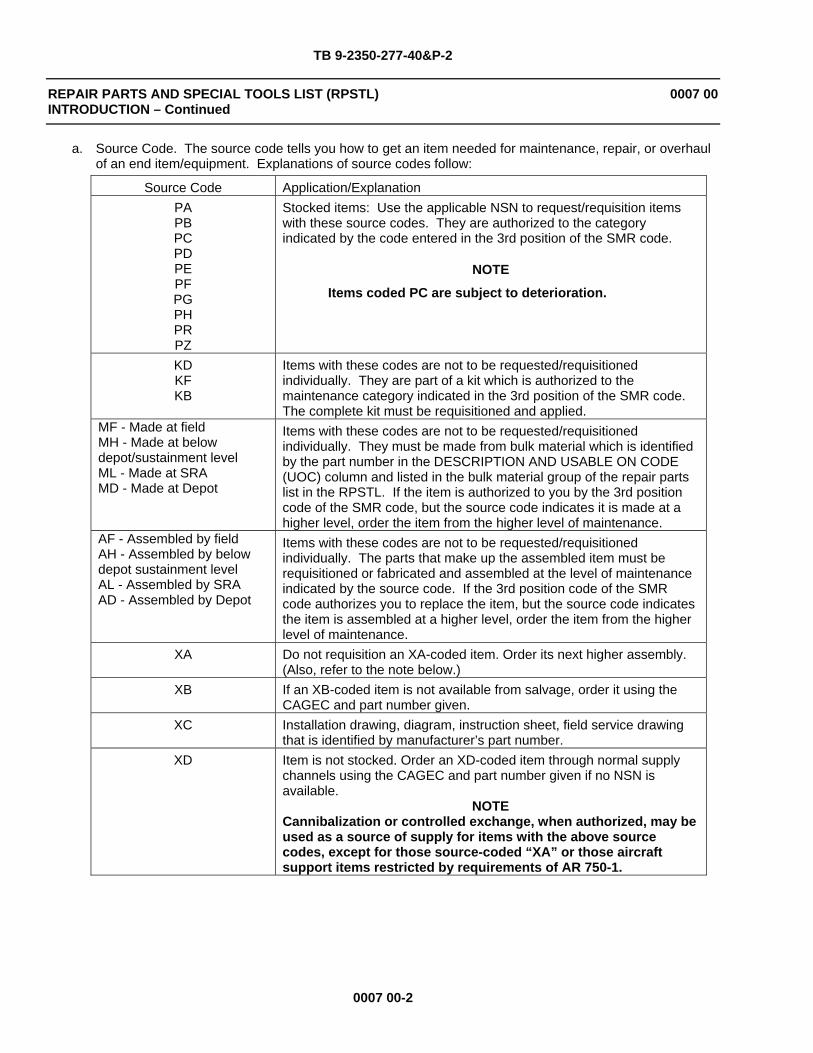
a. Source Code. The source code tells you how to get an item needed for maintenance, repair, or overhaul of an end item/equipment. Explanations of source codes follow:
Source Code Application/Explanation PAPBPCPDPEPFPGPHPRPZ
Stocked items: Use the applicable NSN to request/requisition items with these source codes. They are authorized to the category indicated by the code entered in the 3rd position of the SMR code.
NOTE
Items coded PC are subject to deterioration.
KDKFKB
Items with these codes are not to be requested/requisitioned individually. They are part of a kit which is authorized to the maintenance category indicated in the 3rd position of the SMR code. The complete kit must be requisitioned and applied.
MF - Made at field MH - Made at below depot/sustainment level ML - Made at SRA MD - Made at Depot
Items with these codes are not to be requested/requisitioned individually. They must be made from bulk material which is identified by the part number in the DESCRIPTION AND USABLE ON CODE (UOC) column and listed in the bulk material group of the repair parts list in the RPSTL. If the item is authorized to you by the 3rd position code of the SMR code, but the source code indicates it is made at a higher level, order the item from the higher level of maintenance.
AF - Assembled by field AH - Assembled by below depot sustainment level AL - Assembled by SRA AD - Assembled by Depot
Items with these codes are not to be requested/requisitioned individually. The parts that make up the assembled item must be requisitioned or fabricated and assembled at the level of maintenance indicated by the source code. If the 3rd position code of the SMR code authorizes you to replace the item, but the source code indicates the item is assembled at a higher level, order the item from the higher level of maintenance.
XA Do not requisition an XA-coded item. Order its next higher assembly. (Also, refer to the note below.)
XB If an XB-coded item is not available from salvage, order it using the CAGEC and part number given.
XC Installation drawing, diagram, instruction sheet, field service drawing that is identified by manufacturer’s part number.
XD Item is not stocked. Order an XD-coded item through normal supply channels using the CAGEC and part number given if no NSN is available.
NOTE Cannibalization or controlled exchange, when authorized, may be used as a source of supply for items with the above source codes, except for those source-coded “XA” or those aircraft support items restricted by requirements of AR 750-1.
TB 9-2350-277-40&P-2
REPAIR PARTS AND SPECIAL TOOLS LIST (RPSTL) 0007 00 INTRODUCTION – Continued
0007 00-3
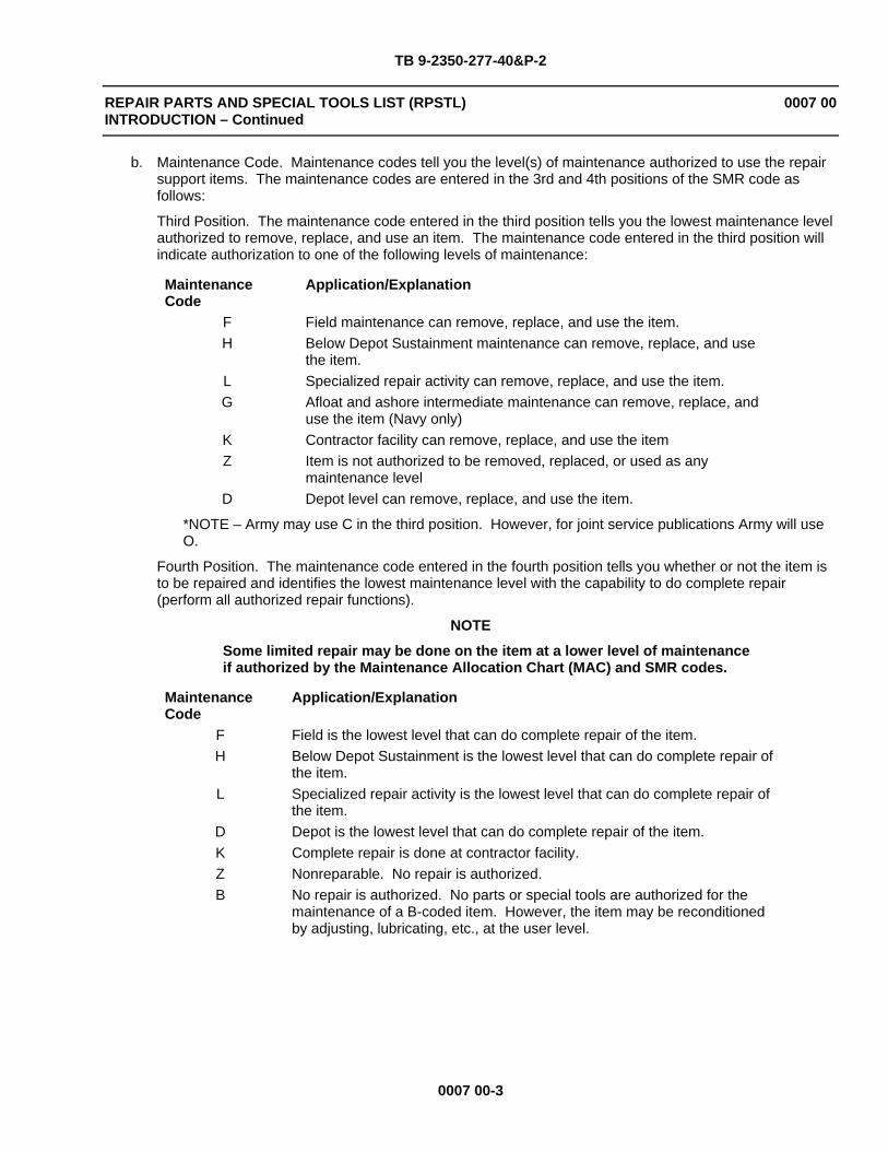
b. Maintenance Code. Maintenance codes tell you the level(s) of maintenance authorized to use the repair support items. The maintenance codes are entered in the 3rd and 4th positions of the SMR code as follows:
Third Position. The maintenance code entered in the third position tells you the lowest maintenance level authorized to remove, replace, and use an item. The maintenance code entered in the third position will indicate authorization to one of the following levels of maintenance:
Maintenance Code
Application/Explanation
F Field maintenance can remove, replace, and use the item. H Below Depot Sustainment maintenance can remove, replace, and use
the item. L Specialized repair activity can remove, replace, and use the item. G Afloat and ashore intermediate maintenance can remove, replace, and
use the item (Navy only) K Contractor facility can remove, replace, and use the item Z Item is not authorized to be removed, replaced, or used as any
maintenance level D Depot level can remove, replace, and use the item.
*NOTE – Army may use C in the third position. However, for joint service publications Army will use O.
Fourth Position. The maintenance code entered in the fourth position tells you whether or not the item is to be repaired and identifies the lowest maintenance level with the capability to do complete repair (perform all authorized repair functions).
NOTE
Some limited repair may be done on the item at a lower level of maintenance if authorized by the Maintenance Allocation Chart (MAC) and SMR codes.
Maintenance Code
Application/Explanation
F Field is the lowest level that can do complete repair of the item. H Below Depot Sustainment is the lowest level that can do complete repair of
the item. L Specialized repair activity is the lowest level that can do complete repair of
the item. D Depot is the lowest level that can do complete repair of the item. K Complete repair is done at contractor facility. Z Nonreparable. No repair is authorized. B No repair is authorized. No parts or special tools are authorized for the
maintenance of a B-coded item. However, the item may be reconditioned by adjusting, lubricating, etc., at the user level.

TB 9-2350-277-40&P-2
REPAIR PARTS AND SPECIAL TOOLS LIST (RPSTL) 0007 00 INTRODUCTION – Continued
0007 00-4
c. Recoverability Code. Recoverability codes are assigned to items to indicate the disposition action on unserviceable items. The recoverability code is entered in the fifth position of the SMR code as follows: Recoverability Code
Application/Explanation
Z Nonreparable item. When unserviceable, condemn and dispose of the item at the level of maintenance shown in 3rd position of SMR code.
F Reparable item. When uneconomically reparable, condemn and dispose of the item at the field level.
H Reparable item. When uneconomically reparable, condemn and dispose of the item at the below depot sustainment level.
D Reparable item. When beyond lower level repair capability, return to depot. Condemnation and disposal of item not authorized below depot level.
L Reparable item. Condemnation and disposal not authorized below Specialized Repair Activity (SRA).
A Item requires special handling or condemnation procedures because of specific reasons (e.g., precious metal content, high dollar value, critical material, or hazardous material). Refer to appropriate manuals/directives for specific instructions.
K Repairable item. Condemnation and disposal to be performed at contractor facility.
National Stock Number (Column (3)). The NSN for the item is listed in this column.
CAGE Code (Column (4)). The Commercial and Government Entity Code (CAGEC) is a 5-digit code which is used to identify the manufacturer, distributor, or Government agency/activity that supplies the item.
Part Number (Column (5)). Indicates the primary number used by the manufacturer (individual, company, firm, corporation, or Government activity), which controls the design and characteristics of the item by means of its engineering drawings, specifications standards, and inspection requirements to identify an item or range of items.
NOTE
When you use an NSN to requisition an item, the item you receive may have a different part number from the number listed.
Description and Usable on Code (UOC) (Column (6)). This column includes the following information:
1. The Federal item name and, when required, a minimum description to identify the item. 2. Part numbers of bulk materials are referenced in this column in the line entry to be manufactured or
fabricated.3. Hardness Critical Item (HCI). A support item that provides the equipment with special protection from
electromagnetic pulse (EMP) damage during a nuclear attack. 4. The statement END OF FIGURE appears just below the last item description in column (6) for a given figure
in both the repair parts list and special tools list work packages.
QTY (Column (7)). The QTY (quantity per figure column) indicates the quantity of the item used in the breakout shown on the illustration figure, which is prepared for a functional group, sub-functional group, or an assembly. A “V” appearing in this column in place of a quantity indicates that no specific quantity is applicable (e.g., shims, spacers).

TB 9-2350-277-40&P-2
REPAIR PARTS AND SPECIAL TOOLS LIST (RPSTL) 0007 00 INTRODUCTION – Continued
0007 00-5/6 blank
EXPLANATION OF CROSS-REFERENCE INDEXES WORK PACKAGES FORMAT AND COLUMNS
1. National Stock Number (NSN) Index Work Package. NSNs in this index are listed in National Item Identification Number (NIIN) sequence.
STOCK NUMBER Column. This column lists the NSN in NIIN sequence. The NIIN consists of the last nine digits of the NSN. When using this column to locate an item, ignore the first four digits of the NSN. However, the complete NSN should be used when ordering items by stock number.
For example, if the NSN is 5385-01-574-1476, the NIIN is 01-574-1476.
FIGURE NUMBER Column. This column lists the number of the figure where the item is identified/located. The figures are in numerical order in the repair parts list work packages.
ITEM Column. The item number identifies the item associated with the figure listed in the adjacent FIGURE column. This item is also identified by the NSN listed on the same line.
2. Part Number (P/N) Index Work Package. Part numbers in this index are listed in ascending alphanumeric sequence (vertical arrangement of letter and number combinations which places the first letter or digit of each group in order A through Z, followed by the numbers 0 through 9 and each following letter or digit in like order).
PART NUMBER Column. Indicates the part number assigned to the item.
FIGURE Column. This column lists the number of the figure where the item is identified/located in the repair parts and special tools list work packages.
ITEM Column. The item number is the number assigned to the item as it appears in the figure referenced in the adjacent figure number column.
END OF WORK PACKAGE

TB 9-2350-277-40&P-2
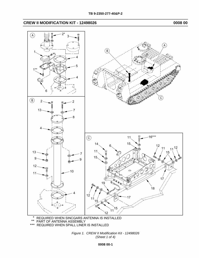
CREW II MODIFICATION KIT - 12498026 0008 00
Figure 1. CREW II Modification Kit - 12498026 (Sheet 1 of 4)
0008 00-1
TB 9-2350-277-40&P-2
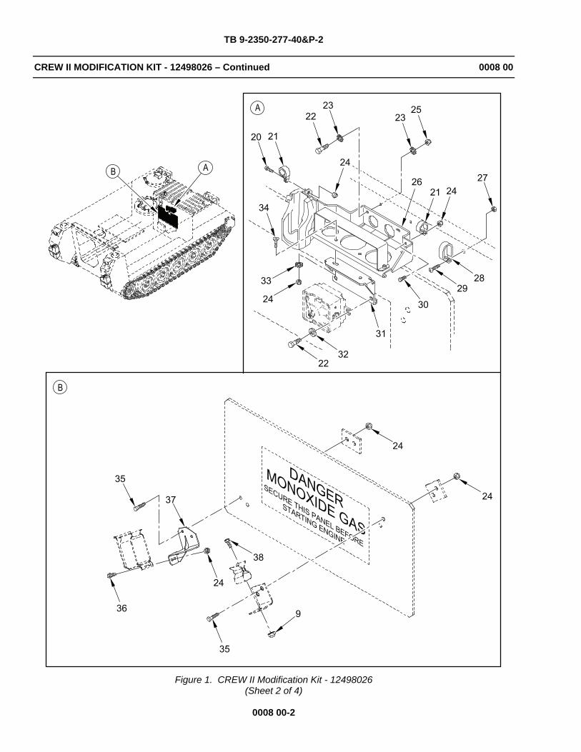
CREW II MODIFICATION KIT - 12498026 – Continued 0008 00
Figure 1. CREW II Modification Kit - 12498026 (Sheet 2 of 4)
0008 00-2

TB 9-2350-277-40&P-2
CREW II MODIFICATION KIT - 12498026 – Continued 0008 00
Figure 1. CREW II Modification Kit - 12498026 (Sheet 3 of 4)
0008 00-3

TB 9-2350-277-40&P-2
CREW II MODIFICATION KIT - 12498026 – Continued 0008 00
Figure 1. CREW II Modification Kit - 12498026 (Sheet 4 of 4)
0008 00-4

TB 9-2350-277-40&P-2
CREW II MODIFICATION KIT - 12498026 – Continued 0008 00
0008 00-5
(1) (2) (3) (4) (5) (6) (7) ITEM SMR NSN PART DESCRIPTION AND NO CAGE NUMBER USABLE ON CODE (UOC) QTY
GROUP 4202 ELECTRICAL CONTROLS (MAIN AND AUXILIARY) CONTINUED FIG. 1. CREW II MODIFICATION KIT 12498026 (M113A3)
1 PAFZZ 5985-01-552-5896 1BEX2 35089 ANTENNA ASSEMBLY.................... 1 UOC:APC, 2 PAFZZ 5305-00-821-3869 80204 B1821BH038C175N SCREW,CAP,HEX HEAD.................. 8 UOC:APC, 3 PAFZZ 5305-00-781-3926 80204 B1821BH038C275N SCREW,CAP,HEX HEAD.................. 4 UOC:APC, 4 PAFZZ 5330-00-772-6600 19270 7726600 GASKET.............................. 4 UOC:APC, 5 PAFZZ 19207 12498024 MOUNT,GPS,CREW II................... 1 UOC:APC, 6 PAFZZ 5975-00-074-2072 96906 MS3367-1-9 STRAP,TIEDOWN,ELECTRICAL............ 50 UOC:APC, 7 PAFZZ 5310-00-080-6004 96906 MS27183-14 WASHER.............................. 6 UOC:APC, 8 PAFZZ 19207 12498048 COVER,ACCESS........................ 1 UOC:APC, 9 PAFZZ 5310-01-505-0245 81349 M45913/1-6CG5Z NUT,SELF-LOCKING,HEX................ 5 UOC:APC, 10 PAFZZ 19207 12498021-2 RISER,ANTENNA....................... 1 UOC:APC, 11 PAFZZ 5310-00-984-7042 80208 MS35338-141 LOCKWASHER.......................... 10 UOC:APC, 12 PAFZZ 5305-00-068-0511 80204 B1821BH038C125N SCREW,CAP,HEX HEAD.................. 8 UOC:APC, 13 PAFZZ 5310-00-061-1258 96906 MS45904-76 LOCKWASHER.......................... 2 UOC:APC, 14 PAFZZ 5305-00-725-2317 80204 B1821BH038C150N SCREW,CAP,HEX HEAD.................. 2 UOC:APC, 15 PAFZZ 5310-00-728-9957 19207 10910174-22 WASHER,FLAT......................... 6 UOC:APC, 16 PAFZZ 5305-00-782-9489 80204 B1821BH038C200N SCREW,CAP,HEX HEAD.................. 2 UOC:APC, 17 PAFZZ 19207 12498020 BRACKET,MOUNTING.................... 2 UOC:APC, 18 PAFZZ 19207 12498029 MOUNT,ELECTRONICS................... 1 UOC:APC, 19 PAFZZ 19207 12498047-1 STRAP,GROUND........................ 1 UOC:APC, 20 PAFZZ 5305-00-071-2506 80204 B1821BH025C050N SCREW,CAP,HEX HEAD.................. 3 UOC:APC, 21 PAFZZ 5340-00-984-8541 80205 MS21333-106 CLAMP,LOOP.......................... 3 UOC:APC, 22 PAFZZ 5306-00-226-4827 80204 B1821BH031C100N BOLT,MACHINE........................ 4 UOC:APC, 23 PAFZZ 5310-00-889-2527 96906 MS45904-72 LOCKWASHER.......................... 4 UOC:APC, 24 PAFZZ 5310-01-505-0247 81349 M45913/1-4CG5Z NUT,SELF-LOCKING,HEX................ 10 UOC:APC, 25 PAFZZ 5310-01-495-9634 81349 M45913-1-5CG5Z NUT,SELF-LOCKING,HEX................ 2 UOC:APC, 26 PAFZZ 19207 12498073 ASSY,MOUNT,PDA/RCU.................. 1 UOC:APC, 27 PAFZZ 5305-00-689-3877 80205 MS17829-3C NUT,SELF-LOCKING,HEX................ 1 UOC:APC, 28 PAFZZ 5340-01-006-9577 80205 MS21334-27 CLAMP,LOOP.......................... 2 UOC:APC, 29 PAFZZ 5305-00-984-6211 96906 MS35206-264 SCREW,MACHINE....................... 1 UOC:APC,

TB 9-2350-277-40&P-2
CREW II MODIFICATION KIT - 12498026 – Continued 0008 00
0008 00-6
(1) (2) (3) (4) (5) (6) (7) ITEM SMR NSN PART DESCRIPTION AND NO CAGE NUMBER USABLE ON CODE (UOC) QTY
30 PAFZZ 5305-00-071-2505 80204 B1821BH025C088N SCREW,CAP,HEX HEAD ................. 1 UOC:APC, 31 PAFZZ 19207 12498075 ASSY,MOUNT,INTERCOM ................ 1 UOC:APC, 32 PAFZZ 5310-00-081-4219 96906 MS27183-12 WASHER ............................. 2 UOC:APC, 33 PAFZZ 5310-00-889-2528 80205 MS45904-68 LOCKWASHER ......................... 2 UOC:APC, 34 PAFZZ 5305-01-382-6007 96906 MS24667-29Z SCREW,CAP,HEX SOCKET ............... 2 UOC:APC, 35 PAFZZ 5305-00-071-2510 80204 B1821BH025C175N SCREW,CAP,HEX HEAD ................. 4 UOC:APC, 36 PAFZZ 5305-00-068-0508 80204 B1821BH025C075N SCREW,CAP,HEX HEAD ................. 2 UOC:APC, 37 PAFZZ 19207 12498078 BRACKET,MOUNTING,CLIP .............. 1 UOC:APC, 38 PAFZZ 5305-01-140-9118 80204 B1821BH038C088N SCREW,CAP,HEX HEAD ................. 1 UOC:APC, 39 PAFZZ 1GVT4 10144-1C CABLE,ANTENNA,N-TYPE ............... 1 UOC:APC, 40 PAFZZ 1GTV4 10139-1C CABLE,ANTENNA,BNC-TYPE ............. 1 UOC:APC, 41 PAFZZ 5305-00-984-6210 80205 MS35206-263 SCREW,MACHINE ...................... 3 UOC:APC, 42 PAFZZ 5310-00-933-8120 80205 MS35338-138 LOCKWASHER ......................... 3 UOC:APC, 43 PAFZZ 5340-00-286-9427 81343 AS21919WDG12 CLAMP,LOOP ......................... 2 UOC:APC, 44 PAFZZ 5310-00-933-8121 96906 MS35338-139 LOCKWASHER ......................... 2 UOC:APC, 45 PAFZZ 5340-00-809-1500 80205 MS21333-107 CLAMP,LOOP ......................... 1 UOC:APC, 46 PAFZZ 1YF27 A3312451-2 POWER HARNESS ...................... 1 UOC:APC, 47 PAFZZ 1YF27 A3312449-5 CABLE,RCU .......................... 1 UOC:APC, 48 PAFZZ 1YF27 A3312450-4 CABLE,RCU TO PDA ................... 1 UOC:APC, 49 PAFZZ 8040-01-501-5557 71984 732RTV ADHESIVE ........................... 1 UOC:APC,
END OF FIGURE
END OF WORK PACKAGE
TB 9-2350-277-40&P-2
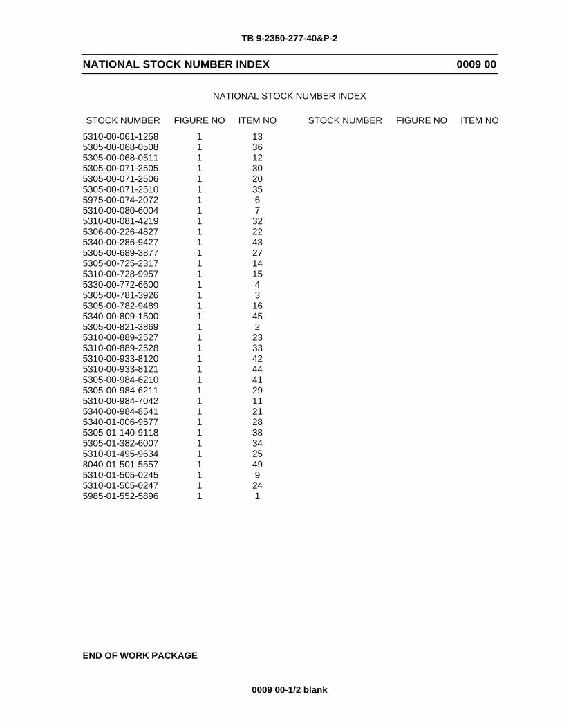
NATIONAL STOCK NUMBER INDEX 0009 00
0009 00-1/2 blank
NATIONAL STOCK NUMBER INDEX
STOCK NUMBER FIGURE NO ITEM NO STOCK NUMBER FIGURE NO ITEM NO
5310-00-061-1258 1 13 5305-00-068-0508 1 36 5305-00-068-0511 1 12 5305-00-071-2505 1 30 5305-00-071-2506 1 20 5305-00-071-2510 1 35 5975-00-074-2072 1 6 5310-00-080-6004 1 7 5310-00-081-4219 1 32 5306-00-226-4827 1 22 5340-00-286-9427 1 43 5305-00-689-3877 1 27 5305-00-725-2317 1 14 5310-00-728-9957 1 15 5330-00-772-6600 1 4 5305-00-781-3926 1 3 5305-00-782-9489 1 16 5340-00-809-1500 1 45 5305-00-821-3869 1 2 5310-00-889-2527 1 23 5310-00-889-2528 1 33 5310-00-933-8120 1 42 5310-00-933-8121 1 44 5305-00-984-6210 1 41 5305-00-984-6211 1 29 5310-00-984-7042 1 11 5340-00-984-8541 1 21 5340-01-006-9577 1 28 5305-01-140-9118 1 38 5305-01-382-6007 1 34 5310-01-495-9634 1 25 8040-01-501-5557 1 49 5310-01-505-0245 1 9 5310-01-505-0247 1 24 5985-01-552-5896 1 1
END OF WORK PACKAGE

TB 9-2350-277-40&P-2
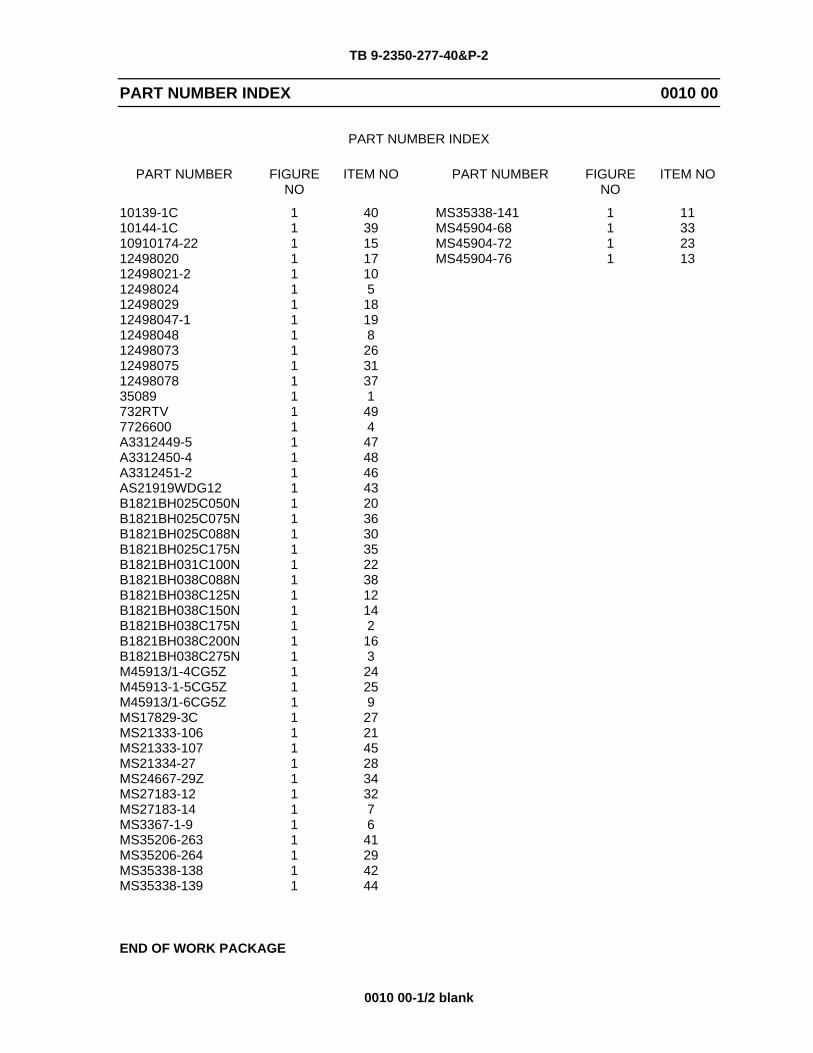
PART NUMBER INDEX 0010 00
0010 00-1/2 blank
PART NUMBER INDEX
PART NUMBER FIGURE NO
ITEM NO PART NUMBER FIGURE NO
ITEM NO
10139-1C 1 40 MS35338-141 1 11 10144-1C 1 39 MS45904-68 1 33 10910174-22 1 15 MS45904-72 1 23 12498020 1 17 MS45904-76 1 13 12498021-2 1 10 12498024 1 5 12498029 1 18 12498047-1 1 19 12498048 1 8 12498073 1 26 12498075 1 31 12498078 1 37 35089 1 1 732RTV 1 49 7726600 1 4 A3312449-5 1 47 A3312450-4 1 48 A3312451-2 1 46 AS21919WDG12 1 43 B1821BH025C050N 1 20 B1821BH025C075N 1 36 B1821BH025C088N 1 30 B1821BH025C175N 1 35 B1821BH031C100N 1 22 B1821BH038C088N 1 38 B1821BH038C125N 1 12 B1821BH038C150N 1 14 B1821BH038C175N 1 2 B1821BH038C200N 1 16 B1821BH038C275N 1 3 M45913/1-4CG5Z 1 24 M45913-1-5CG5Z 1 25 M45913/1-6CG5Z 1 9 MS17829-3C 1 27 MS21333-106 1 21 MS21333-107 1 45 MS21334-27 1 28 MS24667-29Z 1 34 MS27183-12 1 32 MS27183-14 1 7 MS3367-1-9 1 6 MS35206-263 1 41 MS35206-264 1 29 MS35338-138 1 42 MS35338-139 1 44
END OF WORK PACKAGE


TB 9-2350-277-40&P-2
CHAPTER 4 SUPPORTING INFORMATION
WORK PACKAGE INDEX
Title Sequence No.
REFERENCES ............................................................................................................................ 0011 00 COMMON TOOLS AND SUPPLEMENTS AND SPECIAL TOOLS/FIXTURES LIST ................ 0012 00 FABRICATED TOOLS................................................................................................................. 0013 00 EXPENDABLE/DURABLE ITEMS LIST...................................................................................... 0014 00 REPLACEMENT KIT PARTS...................................................................................................... 0015 00


TB 9-2350-277-40&P-2
REFERENCES 0011 00
0011 00-1/2 blank
SCOPE
This work package lists all field manuals, forms, technical manuals, and miscellaneous publications referenced in this manual.
FIELD MANUALS
First Aid for Soldiers FM 4-25.11
FORMS
Recommended Changes to Publications and Blank Forms DA Form 2028
MISCELLANEOUS PUBLICATIONS
Army Material Maintenance Policy AR 750-1
Army Medical Department Expendable/Durable Items CTA 8-100
Army Modification Program AR 750-10
Expendable/Durable Items (except Medical, Class V Repair Parts, and Heraldic Items)
CTA 50-970
Field and Garrison Furnishings and Equipment CTA 50-909
Requisition, Receipt, and Issue System AR 725-50
The Army Maintenance Management System (TAMMS) User’s Manual DA PAM 750-8
TECHNICAL MANUALS
Operator's Manual for Carrier, Personnel, Full-Tracked, Armored, M113A3; Carrier, Command Post, Light Tracked, M577A3; Carrier, Smoke Generator, Full Tracked, M1059A3; Carrier, Mortar, 120-MM M121, Self Propelled, M1064A3; Carrier, Standardized Integrated Command Post System (SICPS) M1068A3; Carrier, Mechanized Smoke Obscurant, M58
TM 9-2350-277-10
Painting Instructions for Army Material TM 43-0139
Unit Maintenance, Direct Support and General Support Maintenance Repair Parts and Special Tools List (Including Depot Maintenance Repair Parts and Special Tools List) for Carriers: M113A3, M577A3, M1059A3, M1064A3, M1068A3, and M58
TM 9-2350-277-24P
Unit Maintenance Manual for Carrier, Personnel, Full Tracked, Armored M113A3; Carrier, Command Post, Light Tracked M577A3; Carrier, Smoke Generator, Full Tracked M1059A3; Carrier, Mortar, 120-MM M121, Self-Propelled M1064A3; Carrier, Standardized Integrated Command Post System (SICPS) M1068A3; Carrier, Mechanized Smoke Obscurant M58
TM 9-2350-277-20 Volumes 1-6
END OF WORK PACKAGE


TB 9-2350-277-40&P-2
COMMON TOOLS AND SUPPLEMENTS AND SPECIAL 0012 00 TOOLS/FIXTURES LIST
0012 00-1
SCOPE
This work package lists all common tools, supplements, and special tools/fixtures needed.
Explanation of Columns
Column (1) – Item Number. This number is assigned to the entry in the list and is referenced in the Initial Setup section of the work package under “Tools” to identify the item (e.g., “General Mechanic’s Tool Kit (WP 0012 00, Item 5)”).
Column (2) – Item Name. This column lists the item by noun nomenclature and other descriptive features (e.g. “Tool Kit, General Mechanic’s”).
Column (3) – National Stock Number. This is the National Stock Number (NSN) assigned to the item; use it to requisition the item.
Column (4) – Part Number. Indicates the primary number used by the manufacturer (individual, company, firm, corporation, or Government activity), which controls the design and characteristics of the item by means of its engineering drawings, specifications, standards, and inspection requirements to identify an item or range of items.
Column (5) – Reference. This column identifies the authorizing Supply Catalog (SC) or Repair Parts and Special Tools List (RPSTL) for items listed in this work package.

TB 9-2350-277-40&P-2
COMMON TOOLS AND SUPPLEMENTS AND SPECIAL 0012 00 TOOLS/FIXTURES LIST – Continued
0012 00-2
Table 1. Tool Identification List
(1)ITEMNO.
(2)ITEM NAME
(3)NATIONAL
STOCK NUMBER
(4)PART NUMBER
(5)REFERENCE
1 Cutoff Saw, Air Powered N/A 4089A51 (07BY4)
2 Die and Tap Set 5180-00-317-8263 41-8789-930-050 (81336) SC 4940-95-B02
3 Drilling Machine, Upright N/A 2805A24 (07BY4)
4 Drill Set, Twist 5133-00-293-0983 DB129B (55719) SC 4910-95-A74
5 General Mechanic’s Tool Kit 5180-00-177-7033 SC 5180-90-CL-N26
(50980) SC 5180-95-N26
6 Goggles, Industrial 4240-00-052-3776 ANSI Z87.1 (80204) SC 4910-95-A81
7 Hole Saw Set, Carbide Tipped N/A TL1-LNS-30801D
8 Measuring Tape 5210-00-554-7085 403
9 Portable Drill, Electric, 1/2 inch 5130-00-889-9004 5130-00-889-9004
(80244) SC 4910-95-A31
10 Sander, Disk, Electric, Portable 5130-00-596-9728 6112-90 (07429) SC 4920-99-A63
11 Wrench, Torque, 1/2 inch Drive, 0-175 ft-lb 5120-00-640-6364 A-A-2411 SC 4940-95-B21
END OF WORK PACKAGE

TB 9-2350-277-40&P-2
FABRICATED TOOLS 0013 00
0013 00-1/2 blank
SCOPE
This work package includes instructions for making tools authorized to be fabricated at sustainment level. These tools are needed for special installation procedures, but are not available in the supply system. The tools are normally fabricated locally when required by the task.
FABRICATION ILLUSTRATIONS
The following figure provides tool fabrication instructions. All parts and bulk materials needed for manufacturing the tool are listed on each figure. When needed, any special explanatory instructions are included in the notes on the figure.
Figure 1. Magnetic Drill Base Plate/Template
MATERIAL REQUIRED
Steel, Plate, 1 inch Thick
NOTES:
1. Fabricate as illustrated.
2. Break all sharp edges and corners.
END OF WORK PACKAGE

TB 9-2350-277-40&P-2
EXPENDABLE/DURABLE ITEMS LIST 0014 00
0014 00-1/2 blank
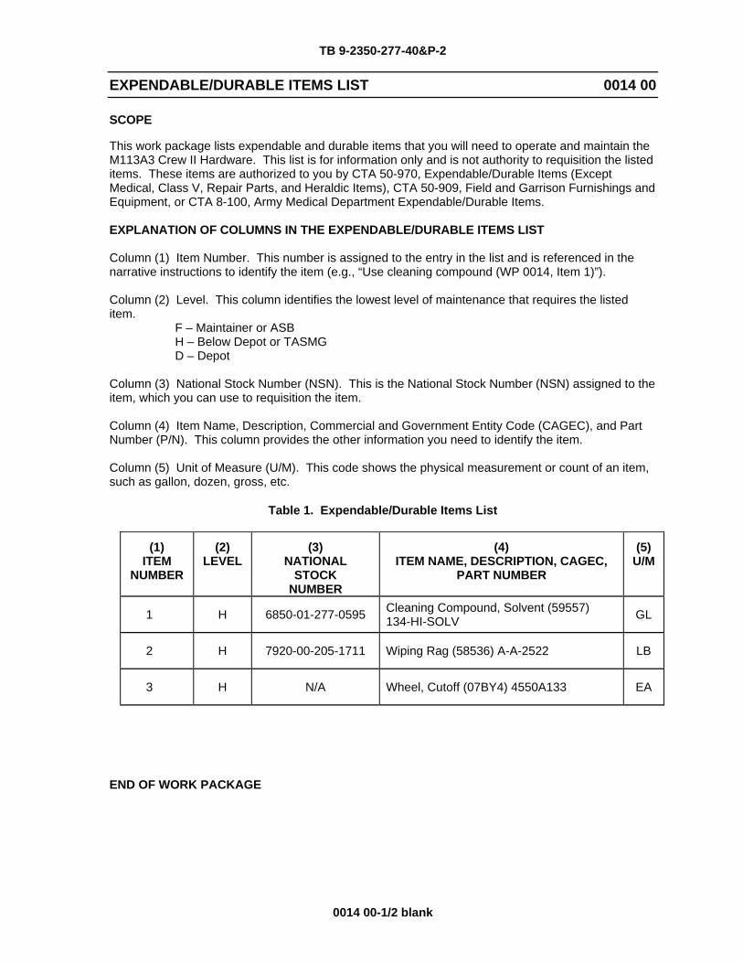
SCOPE
This work package lists expendable and durable items that you will need to operate and maintain the M113A3 Crew II Hardware. This list is for information only and is not authority to requisition the listed items. These items are authorized to you by CTA 50-970, Expendable/Durable Items (Except Medical, Class V, Repair Parts, and Heraldic Items), CTA 50-909, Field and Garrison Furnishings and Equipment, or CTA 8-100, Army Medical Department Expendable/Durable Items.
EXPLANATION OF COLUMNS IN THE EXPENDABLE/DURABLE ITEMS LIST
Column (1) Item Number. This number is assigned to the entry in the list and is referenced in the narrative instructions to identify the item (e.g., “Use cleaning compound (WP 0014, Item 1)”).
Column (2) Level. This column identifies the lowest level of maintenance that requires the listed item. F – Maintainer or ASB H – Below Depot or TASMG D – Depot
Column (3) National Stock Number (NSN). This is the National Stock Number (NSN) assigned to the item, which you can use to requisition the item.
Column (4) Item Name, Description, Commercial and Government Entity Code (CAGEC), and Part Number (P/N). This column provides the other information you need to identify the item.
Column (5) Unit of Measure (U/M). This code shows the physical measurement or count of an item, such as gallon, dozen, gross, etc.
Table 1. Expendable/Durable Items List
(1)ITEM
NUMBER
(2)LEVEL
(3)NATIONAL
STOCKNUMBER
(4)ITEM NAME, DESCRIPTION, CAGEC,
PART NUMBER
(5)U/M
1 H 6850-01-277-0595 Cleaning Compound, Solvent (59557) 134-HI-SOLV GL
2 H 7920-00-205-1711 Wiping Rag (58536) A-A-2522 LB
3 H N/A Wheel, Cutoff (07BY4) 4550A133 EA
END OF WORK PACKAGE


TB 9-2350-277-40&P-2
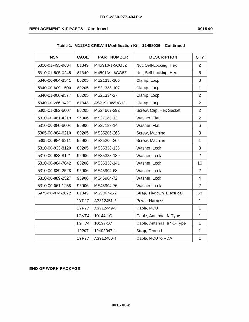
REPLACEMENT KIT PARTS 0015 00
0015 00-1
SCOPE
This work package includes a table of modification kit parts required for CREW II. The unique components of this list may not currently be available through the normal supply system.
Table 1. M113A3 CREW II Modification Kit - 12498026
NSN CAGE PART NUMBER DESCRIPTION QTY
5985-01-552-5896 1BEX2 35089 Antenna Assembly 1
5330-00-772-6600 19270 7726600 Gasket 4
8040-01-501-5557 71984 732RTV Adhesive 1
5310-00-728-9957 19207 10910174-22 Washer, Flat 6
19207 12498020 Bracket, Mounting 2
19207 12498021-2 Riser, Antenna 1
19207 12498024 Mount, GPS, CREW II 1
19207 12498029 Mount, Electronics 1
19207 12498048 Cover, Access 1
19207 12498073 Assy, Mount, PDA/RCU 1
19207 12498075 Assy, Mount, Intercom 1
19207 12498078 Bracket, Mounting, Clip 1
5305-00-071-2506 80204 B1821BH025C050N Screw, Cap, Hex Head 3
5305-00-068-0508 80204 B1821BH025C075N Screw, Cap, Hex Head 2
5305-00-071-2505 80204 B1821BH025C088N Screw, Cap, Hex Head 1
5305-00-071-2510 80204 B1821BH025C175N Screw, Cap, Hex Head 4
5306-00-226-4827 80204 B1821BH031C100N Bolt, Machine 4
5305-01-140-9118 80204 B1821BH038C088N Screw, Cap, Hex Head 1
5305-00-068-0511 80204 B1821BH038C125N Screw, Cap, Hex Head 8
5305-00-725-2317 80204 B1821BH038C150N Screw, Cap, Hex Head 2
5305-00-821-3869 80204 B1821BH038C175N Screw, Cap, Hex Head 8
5305-00-782-9489 80204 B1821BH038C200N Screw, Cap, Hex Head 2
5305-00-781-3926 80204 B1821BH038C275N Screw, Cap, Hex Head 4
5305-00-689-3877 80205 MS17829-3C Nut, Self-Locking, Hex 1
5310-01-505-0247 81349 M45913/1-4CG5Z Nut, Self-Locking, Hex 10
TB 9-2350-277-40&P-2
REPLACEMENT KIT PARTS – Continued 0015 00
0015 00-2
Table 1. M113A3 CREW II Modification Kit - 12498026 – Continued
NSN CAGE PART NUMBER DESCRIPTION QTY
5310-01-495-9634 81349 M45913-1-5CG5Z Nut, Self-Locking, Hex 2
5310-01-505-0245 81349 M45913/1-6CG5Z Nut, Self-Locking, Hex 5
5340-00-984-8541 80205 MS21333-106 Clamp, Loop 3
5340-00-809-1500 80205 MS21333-107 Clamp, Loop 1
5340-01-006-9577 80205 MS21334-27 Clamp, Loop 2
5340-00-286-9427 81343 AS21919WDG12 Clamp, Loop 2
5305-01-382-6007 80205 MS24667-29Z Screw, Cap, Hex Socket 2
5310-00-081-4219 96906 MS27183-12 Washer, Flat 2
5310-00-080-6004 96906 MS27183-14 Washer, Flat 6
5305-00-984-6210 80205 MS35206-263 Screw, Machine 3
5305-00-984-6211 96906 MS35206-264 Screw, Machine 1
5310-00-933-8120 80205 MS35338-138 Washer, Lock 3
5310-00-933-8121 96906 MS35338-139 Washer, Lock 2
5310-00-984-7042 80208 MS35338-141 Washer, Lock 10
5310-00-889-2528 96906 MS45904-68 Washer, Lock 2
5310-00-889-2527 96906 MS45904-72 Washer, Lock 4
5310-00-061-1258 96906 MS45904-76 Washer, Lock 2
5975-00-074-2072 81343 MS3367-1-9 Strap, Tiedown, Electrical 50
1YF27 A3312451-2 Power Harness 1
1YF27 A3312449-5 Cable, RCU 1
1GVT4 10144-1C Cable, Antenna, N-Type 1
1GTV4 10139-1C Cable, Antenna, BNC-Type 1
19207 12498047-1 Strap, Ground 1
1YF27 A3312450-4 Cable, RCU to PDA 1
END OF WORK PACKAGE

TB 9-2350-277-40&P-2
INDEX-1
INDEX
A – B
C – D
Common Tools and Supplements and Special Tools/Fixtures List ................................................... 0012 00-1 Crew II Modification Kit - 12498026 ................................................................................................... 0008 00-1
E
Equipment Description ....................................................................................................................... 0002 00-1 Expendable/Durable Items List .......................................................................................................... 0014 00-1
F
Fabricated Tools ................................................................................................................................ 0013 00-1
G – H
I
Installation Procedures GPS Antenna Cables...................................................................................................................... 0006 00-15 GPS Antenna Cable Clamps and Power Harness Clamps ............................................................ 0006 00-14 GPS Antenna Riser......................................................................................................................... 0006 00-8 GPS Kit ........................................................................................................................................... 0006 00-2 Power Harness, RCU Cable, RCU to PDA Cable, and GPS Cable ............................................... 0006 00-16 Power Plant Upper Rear Access Panel .......................................................................................... 0006 00-9 Primary Unit Mounting Bracket Assembly ...................................................................................... 0006 00-13 RCU/PDA Bracket Assembly.......................................................................................................... 0006 00-10 RCU/PDA Cable Clamps and Commander’s Intercom Unit ........................................................... 0006 00-11
Introduction General ........................................................................................................................................... 0001 00-1 Purpose........................................................................................................................................... 0001 00-1
J – L
M
Modification Procedures Clearance for CREW II Primary Unit .............................................................................................. 0005 00-5 Drill CREW II Engine Bulkhead Cable Clamp ................................................................................ 0005 00-6 Drill CREW II GPS Antenna Riser Cable Port ................................................................................ 0005 00-1 Drill CREW II Hull Roof Cable Clamp............................................................................................. 0005 00-7 Drill CREW II Primary Unit Mounting Bracket................................................................................. 0005 00-4
N
National Stock Number Index ............................................................................................................ 0009 00-1
O
P
Part Number Index ............................................................................................................................. 0010 00-1

TB 9-2350-277-40&P-2
INDEX-2
Q
R
References .........................................................................................................................................0011 00-1
Removal Procedures Power Plant Upper Rear Access Panel ..........................................................................................0003 00-1 Engine Bulkhead Hardware or Commander’s Intercom Unit ..........................................................0003 00-2 Spall Liner Right Angle Bracket Hardware......................................................................................0003 00-4
Replacement Kit Parts ........................................................................................................................0015 00-1
Rework Procedures Disassemble Power Plant Upper Rear Access Panel.....................................................................0004 00-1 Assemble Power Plant Upper Rear Access Panel .........................................................................0004 00-2
Repair Parts and Special Tools List (RPSTL) CREW II Modification Kit - 12498026..............................................................................................0008 00-1 Explanation of Columns in the Repair Parts List and Special Tools List Work Packages..............0007 00-1 Explanation of Cross-Reference Indexes Work Packages Format and Columns ..........................0007 00-5 General............................................................................................................................................0007 00-1 National Stock Number Index .........................................................................................................0009 00-1 Part Number Index ..........................................................................................................................0010 00-1 Scope ..............................................................................................................................................0007 00-1
S
T
Tools/Fixture List, Common Tools and Supplements and Special.....................................................0012 00-1
U – Z
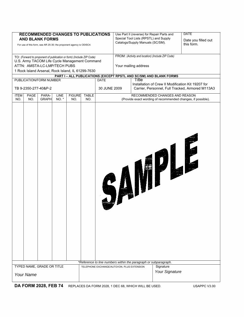
RECOMMENDED CHANGES TO PUBLICATIONS AND BLANK FORMS
For use of this form, see AR 25-30; the proponent agency is ODISC4.
Use Part II (reverse) for Repair Parts and Special Tool Lists (RPSTL) and Supply Catalogs/Supply Manuals (SC/SM).
DATE
Date you filled out this form.
TO: (Forward to proponent of publication or form) (Include ZIP Code) U.S. Army TACOM Life Cycle Management Command ATTN: AMSTA-LC-LMP/TECH PUBS 1 Rock Island Arsenal, Rock Island, IL 61299-7630
FROM: (Activity and location) (Include ZIP Code)
Your mailing address
PART I – ALL PUBLICATIONS (EXCEPT RPSTL AND SC/SM) AND BLANK FORMS PUBLICATION/FORM NUMBER DATE Title Installation of Crew II Modification Kit 19207 for TB 9-2350-277-40&P-2 30 JUNE 2009 Carrier, Personnel, Full Tracked, Armored M113A3 ITEMNO.
PAGENO.
PARA-GRAPH
LINENO. *
FIGURENO.
TABLENO.
RECOMMENDED CHANGES AND REASON (Provide exact wording of recommended changes, if possible).
*Reference to line numbers within the paragraph or subparagraph. TYPED NAME, GRADE OR TITLE
Your Name
TELEPHONE EXCHANGE/AUTOVON, PLUS EXTENSION Signature
Your Signature
DA FORM 2028, FEB 74 REPLACES DA FORM 2028, 1 DEC 68, WHICH WILL BE USED. USAPPC V3.00

TO: (Forward direct to addressee listed in publication) U. S. Army TACOM Life Cycle Management Command ATTN: AMSTA-LC-LMPP/TECH PUBS 1 Rock Island Arsenal, Rock Island, IL 61299-7630
FROM: (Activity and location) (Include ZIP Code)
Your address DATEDate you filled out this form
PART II – REPAIR PARTS AND SPECIAL TOOL LISTS AND SUPPLY CATALOGS/SUPPLY MANUALS PUBLICATION NUMBER DATE TITLE Installation of Crew II Modification Kit
PAGENO.
COLMNO.
LINENO.
NATIONAL STOCK NUMBER
REFERENCENO.
FIGURENO.
ITEMNO.
TOTAL NO.OF MAJOR
ITEMSSUPPORTED
RECOMMENDED ACTION
PART III – REMARKS (Any general remarks or recommendations, or suggestions for improvement of publications and blank forms. Additional blank sheets may be used if more space is needed.)
TYPED NAME, GRADE OR TITLE
Your Name
TELEPHONE EXCHANGE/AUTOVON, PLUS EXTENSION SIGNATURE
Your Signature
USAPPC V3.00
SAMPLE
TB 9-2350-277-40&P-2 30 June 2009 for Carrier, Personnel, Full Tracked, M113A3

RECOMMENDED CHANGES TO PUBLICATIONS AND BLANK FORMS
For use of this form, see AR 25-30; the proponent agency is ODISC4.
Use Part II (reverse) for Repair Parts and Special Tool Lists (RPSTL) and Supply Catalogs/Supply Manuals (SC/SM).
DATE
U.S. Army TACOM Life Cycle Management Command ATTN: AMSTA-LC-LMPP/TECH PUBS 1 Rock Island Arsenal, Rock Island, IL 61299-7630
FROM: (Activity and location) (Include ZIP Code)
PART I – ALL PUBLICATIONS (EXCEPT RPSTL AND SC/SM) AND BLANK FORMS PUBLICATION/FORM NUMBER DATE TITLE Installation of Crew II Modification Kit 19207
TB 9-2350-277-40&P-2 30 June 2009 for Carrier, Personnel, Full Tracked, Armored M113A3
ITEMNO.
PAGENO.
PARA-GRAPH
LINENO. *
FIGURENO.
TABLENO.
RECOMMENDED CHANGES AND REASON (Provide exact wording of recommended changes, if possible).
*Reference to line numbers within the paragraph or subparagraph.
TYPED NAME, GRADE OR TITLE TELEPHONE EXCHANGE/AUTOVON, PLUS EXTENSION
SIGNATURE
DA FORM 2028, FEB 74 REPLACES DA FORM 2028, 1 DEC 68, WHICH WILL BE USED. USAPPC V3.00
TO: (Forward to proponent of publication or form)(Include ZIP Code)

TO: (Forward direct to addressee listed in publication) U. S. Army TACOM Life Cycle Management Command ATTN: AMSTA-LC-LMPP/TECH PUBS1 Rock Island Arsenal, Rock Island, IL 61299-7630
FROM: (Activity and location) (Include ZIP Code) DATE
PART II – REPAIR PARTS AND SPECIAL TOOL LISTS AND SUPPLY CATALOGS/SUPPLY MANUALS
PUBLICATION NUMBER DATE TITLE Installation of Crew II Modification Kit for
PAGENO.
COLMNO.
LINENO.
NATIONAL STOCK NUMBER
REFERENCENO.
FIGURENO.
ITEMNO.
TOTAL NO.OF MAJOR
ITEMSSUPPORTED
RECOMMENDED ACTION
PART III – REMARKS (Any general remarks or recommendations, or suggestions for improvement of publications and blank forms. Additional blank sheets may be used if more space is needed.)
TYPED NAME, GRADE OR TITLE TELEPHONE EXCHANGE/AUTOVON, PLUS EXTENSION SIGNATURE
USAPPC V3.00
TB 9-2350-277-40&P-2 30 June 2009 Carrier, Personnel, Full-Tracked,Armored M113A3
RECOMMENDED CHANGES TO PUBLICATIONS AND BLANK FORMS
For use of this form, see AR 25-30; the proponent agency is ODISC4.
Use Part II (reverse) for Repair Parts and Special Tool Lists (RPSTL) and Supply Catalogs/Supply Manuals (SC/SM).
DATE
TO: (Forward to proponent of publication or form) (Include ZIP Code) U. S. Army TACOM Life Cycle Management Command ATTN: AMSTA-LC-LMPP/TECH PUBS 1 Rock Island Arsenal, Rock Island, IL 61299-7630
FROM: (Activity and location) (Include ZIP Code)
PUBLICATION/FORM NUMBER DATE TITLE Installation of Crew II Modificati for TB 9-2350-277-40&P-2 30 June 2009 Carrier, Personnel, Full Tracked Armored, M113A3
ITEM NO.
PAGENO.
PARA-GRAPH
LINE NO. *
FIGURENO.
TABLENO.
RECOMMENDED CHANGES AND REASON (Provide exact wording of recommended changes, if possible).
*Reference to line numbers within the paragraph or subparagraph.
TYPED NAME, GRADE OR TITLE TELEPHONE EXCHANGE/AUTOVON, PLUS EXTENSION
SIGNATURE
DA FORM 2028, FEB 74 REPLACES DA FORM 2028, 1 DEC 68, WHICH WILL BE USED. USAPPC V3.00

TO: (Forward direct to addressee listed in publication)U. S. Army TACOM Life Cycle Management Command ATTN: AMSTA-LC-LMPP/TECH PUBS1 Rock Island Arsenal, Rock Island, IL 61299-7630
FROM: (Activity and location) (Include ZIP Code) DATE
PART II – REPAIR PARTS AND SPECIAL TOOL LISTS AND SUPPLY CATALOGS/SUPPLY MANUALS
PUBLICATION NUMBER DATE TITLE Installation of Crew II Modification Kit, for TB 9-2350-277-40&P-2 30 June 2009 Carrier, Personnell, jll Tracked, Armored M113A3
PAGENO.
COLMNO.
LINENO.
NATIONAL STOCK NUMBER
REFERENCENO.
FIGURENO.
ITEMNO.
TOTAL NO.OF MAJOR
ITEMSSUPPORTED
RECOMMENDED ACTION
PART III – REMARKS (Any general remarks or recommendations, or suggestions for improvement of publications and blank forms. Additional blank sheets may be used if more space is needed.)
TYPED NAME, GRADE OR TITLE TELEPHONE EXCHANGE/AUTOVON, PLUS EXTENSION SIGNATURE
USAPPC V3.00

RECOMMENDED CHANGES TO PUBLICATIONS AND BLANK FORMS
For use of this form, see AR 25-30; the proponent agency is ODISC4.
Use Part II (reverse) for Repair Parts and Special Tool Lists (RPSTL) and Supply Catalogs/Supply Manuals (SC/SM).
DATE
TO: (Forward to proponent of publication or form) (Include ZIP Code) U. S. Army TACOM Life Cycle Management Command ATTN: AMSTA-LC-LMPP/TECH PUBS 1 Rock Island Arsenal, Rock Island, IL 61299-7630
FROM: (Activity and location) (Include ZIP Code)
PUBLICATION/FORM NUMBER DATE TITLE Installation of Crew II Modificati for TB 9-2350-277-40&P-2 30 June 2009 Carrier, Personnel, Full Tracked Armored, M113A3
ITEM NO.
PAGENO.
PARA-GRAPH
LINE NO. *
FIGURENO.
TABLENO.
RECOMMENDED CHANGES AND REASON (Provide exact wording of recommended changes, if possible).
*Reference to line numbers within the paragraph or subparagraph.
TYPED NAME, GRADE OR TITLE TELEPHONE EXCHANGE/AUTOVON, PLUS EXTENSION
SIGNATURE
DA FORM 2028, FEB 74 REPLACES DA FORM 2028, 1 DEC 68, WHICH WILL BE USED. USAPPC V3.00
TO: (Forward direct to addressee listed in publication)U. S. Army TACOM Life Cycle Management Command ATTN: AMSTA-LC-LMPP/TECH PUBS1 Rock Island Arsenal, Rock Island, IL 61299-7630
FROM: (Activity and location) (Include ZIP Code) DATE
PART II – REPAIR PARTS AND SPECIAL TOOL LISTS AND SUPPLY CATALOGS/SUPPLY MANUALS
PUBLICATION NUMBER DATE TITLE Installation of Crew II Modification Kit, for TB 9-2350-277-40&P-2 30 June 2009 Carrier, Personnell, jll Tracked, Armored M113A3
PAGENO.
COLMNO.
LINENO.
NATIONAL STOCK NUMBER
REFERENCENO.
FIGURENO.
ITEMNO.
TOTAL NO.OF MAJOR
ITEMSSUPPORTED
RECOMMENDED ACTION
PART III – REMARKS (Any general remarks or recommendations, or suggestions for improvement of publications and blank forms. Additional blank sheets may be used if more space is needed.)
TYPED NAME, GRADE OR TITLE TELEPHONE EXCHANGE/AUTOVON, PLUS EXTENSION SIGNATURE
USAPPC V3.00

TB 9-2350-277-40&P-2
Distribution:
To be distributed in accordance with the initial distribution number (IDN) 344979 requirements for TB 9-2350-277-40&P-2.
By Order of the Secretary of the Army:
GEORGE W. CASEY, JR. General, United States Army
Chief of StaffOfficial:
0914702
JOYCE E. MORROW Administrative Assistant to the
Secretary of the Army


THE METRIC SYSTEM AND EQUIVALENTS
LINEAR MEASURE SQUARE MEASURE 1 Centimeter = 10 Millimeters = 0.01 Meters = 0.3937 Inches 1 Sq. Centimeter = 100 Sq. Millimeters = 0.155 Sq. Inches 1 Meter = 100 Centimeters = 1000 Millimeters = 39.37 Inches 1 Sq. Meter = 10,000 Sq. Centimeters = 10.76 Sq. Feet 1 Kilometer = 1000 Meters = 0.621 Miles 1 Sq. Kilometer = 1,000 Sq. Meters = 0.386 Sq. Miles WEIGHTS CUBIC MEASURE 1 Gram = 0.001 Kilograms = 1000 Milligrams = 0.035 Ounces 1 Cu. Centimeter = 1000 Cu. Millimeters = 0.06 Cu. Inches 1 Kilogram = 1000 Grams = 2.2 Lb. 1 Cu. Meter = 1,000,000 Cu. Centimeters = 35.31 Cu. Feet 1 Metric Ton = 1000 Kilograms = 1 Megagram = 1.1 Short Tons TEMPERATURELIQUID MEASURE 5/9 (ºF - 32) = ºC1 Milliliter = 0.001 Liters = 0.0338 Fluid Ounces 212º Fahrenheit is equivalent to 100º Celsius 1 Liter = 1000 Milliliters = 33.82 Fluid Ounces 90º Fahrenheit is equivalent to 32.2º Celsius
32º Fahrenheit is equivalent to 0º Celsius (9/5 x ºC) + 32 = ºF
TO CHANGE TO MULTIPLY BY Inches ..................................... Centimeters............................... 2.540 Feet ........................................ Meters ....................................... 0.305 Yards ...................................... Meters ....................................... 0.914 Miles ....................................... Kilometers ................................. 1.609 Square Inches ........................ Square Centimeters .................. 6.451 Square Feet............................ Square Meters .......................... 0.093 Square Yards.......................... Square Meters .......................... 0.836 Square Miles........................... Square Kilometers .................... 2.590 Acres ...................................... Square Hectometers ................. 0.405 Cubic Feet .............................. Cubic Meters............................. 0.028 Cubic Yards ............................ Cubic Meters............................. 0.765 Fluid Ounces .......................... Milliliters .................................. 29.573 Pints........................................ Liters ......................................... 0.473 Quarts..................................... Liters ......................................... 0.946 Gallons ................................... Liters ......................................... 3.785 Ounces ................................... Grams ..................................... 28.349 Pounds ................................... Kilograms .................................. 0.454 Short Tons .............................. Metric Tons ............................... 0.907 Pound-Feet............................. Newton-Meters.......................... 1.356 Pounds per Square Inch......... Kilopascals................................ 6.895 Miles per Gallon...................... Kilometers per Liter................... 0.425 Miles per Hour ........................ Kilometers per Hour .................. 1.609
TO CHANGE TO MULTIPLY BY Centimeters ............................ Inches ....................................... 0.394 Meters..................................... Feet........................................... 3.280 Meters..................................... Yards......................................... 1.094 Kilometers............................... Miles.......................................... 0.621 Square Centimeters................ Square Inches........................... 0.155 Square Meters ........................ Square Feet ............................ 10.764 Square Meters ........................ Square Yards ............................ 1.196 Square Kilometers .................. Square Miles ............................. 0.386 Square Hectometers............... Acres......................................... 2.471 Cubic Meters .......................... Cubic Feet............................... 35.315 Cubic Meters .......................... Cubic Yards .............................. 1.308 Milliliters.................................. Fluid Ounces............................. 0.034 Liters....................................... Pints .......................................... 2.113 Liters....................................... Quarts ....................................... 1.057 Liters....................................... Gallons...................................... 0.264 Grams..................................... Ounces...................................... 0.035 Kilograms................................ Pounds...................................... 2.205 Metric Tons............................. Short Tons ................................ 1.102 Newton-Meters ....................... Pound-Feet ............................... 0.738 Kilopascals ............................. Pounds per Square Inch ........... 0.145 Kilometers per Liter ................ Miles per Gallon ........................ 2.354 Kilometers per Hour................ Miles per Hour........................... 0.621

PIN: 085516-000