Embed Size (px)
Citation preview
ARCH 631 Note Set 20 F2016abn
403
Case Study in Timber adapted from Simplified Design of Wood Structures, James Ambrose, 5th ed.
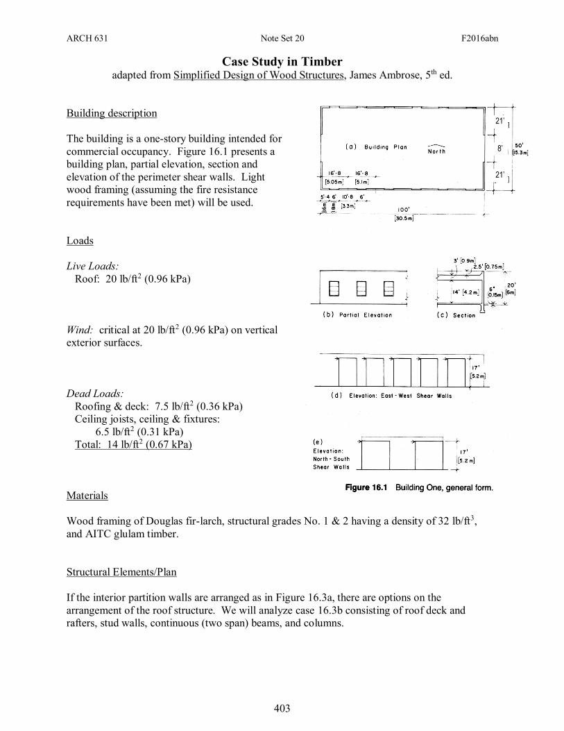
Building description
The building is a one-story building intended for
commercial occupancy. Figure 16.1 presents a
building plan, partial elevation, section and
elevation of the perimeter shear walls. Light
wood framing (assuming the fire resistance
requirements have been met) will be used.
Loads
Live Loads:
Roof: 20 lb/ft2 (0.96 kPa)
Wind: critical at 20 lb/ft2 (0.96 kPa) on vertical
exterior surfaces.
Dead Loads:
Roofing & deck: 7.5 lb/ft2 (0.36 kPa)
Ceiling joists, ceiling & fixtures:
6.5 lb/ft2 (0.31 kPa)
Total: 14 lb/ft2 (0.67 kPa)
Materials
Wood framing of Douglas fir-larch, structural grades No. 1 & 2 having a density of 32 lb/ft3,
and AITC glulam timber.
Structural Elements/Plan
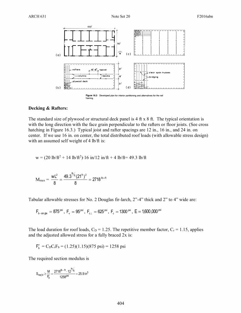
If the interior partition walls are arranged as in Figure 16.3a, there are options on the
arrangement of the roof structure. We will analyze case 16.3b consisting of roof deck and
rafters, stud walls, continuous (two span) beams, and columns.
21’
21’
8’
ARCH 631 Note Set 20 F2016abn
404
Decking & Rafters:
The standard size of plywood or structural deck panel is 4 ft x 8 ft. The typical orientation is
with the long direction with the face grain perpendicular to the rafters or floor joists. (See cross
hatching in Figure 16.3.) Typical joist and rafter spacings are 12 in., 16 in., and 24 in. on
center. If we use 16 in. on center, the total distributed roof loads (with allowable stress design)
with an assumed self weight of 4 lb/ft is:
w = (20 lb/ft2 + 14 lb/ft2)16 in/12 in/ft + 4 lb/ft= 49.3 lb/ft
Mmax = ftlb
2ftftlb
2
27188
)21(3.49
8
wL
Tabular allowable stresses for No. 2 Douglas fir-larch, 2”-4” thick and 2” to 4” wide are:
psi
glesinb 875F , psi
v 95F , psi
c 625F , psi
c 1300F , psi000,600,1E
The load duration for roof loads, CD = 1.25. The repetitive member factor, Cr = 1.15, applies
and the adjusted allowed stress for a fully braced 2x is:
bF = CDCrFb = (1.25)(1.15)(875 psi) = 1258 psi
The required section modulus is
3
psi
ftin
ftlb
bd'req in9.25
1258
122718
F
MS
ARCH 631 Note Set 20 F2016abn
405
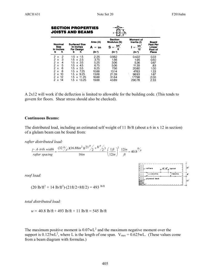
A 2x12 will work if the deflection is limited to allowable for the building code. (This tends to
govern for floors. Shear stress should also be checked).
Continuous Beams:
The distributed load, including an estimated self weight of 11 lb/ft (about a 6 in x 12 in section)
of a glulam beam can be found from:
rafter distributed load:
ftlb
ftft
ftlb
ft
in
in
ft
in
in
spacingrafter
widthtribA8.40
12
12
1
16
)2
82
21)(88.16)(32(.22
3
roof load:
(20 lb/ft2 + 14 lb/ft2)(21ft/2+8ft/2) = 493 lb/ft
total distributed load:
w = 40.8 lb/ft + 493 lb/ft + 11 lb/ft = 545 lb/ft
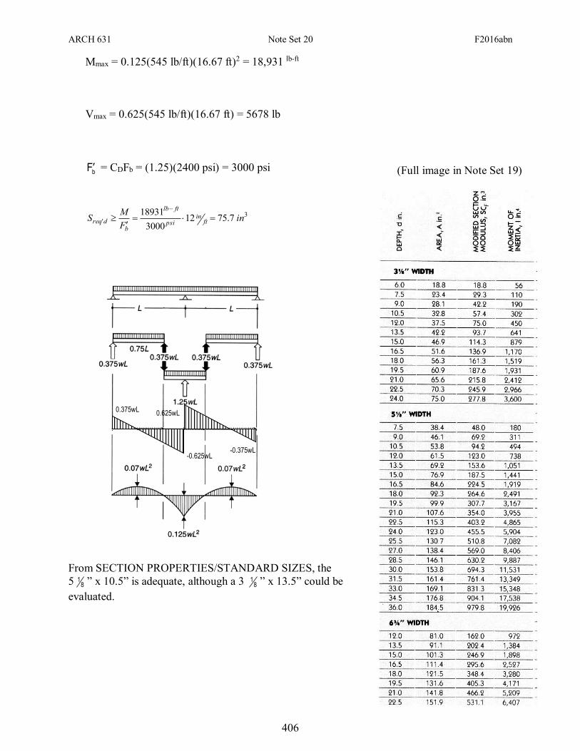
The maximum positive moment is 0.07wL2 and the maximum negative moment over the
support is 0.125wL2, where L is the length of one span. Vmax = 0.625wL. (These values come
from a beam diagram with formulas.)
ARCH 631 Note Set 20 F2016abn
406
Mmax = 0.125(545 lb/ft)(16.67 ft)2 = 18,931 lb-ft
Vmax = 0.625(545 lb/ft)(16.67 ft) = 5678 lb
bF = CDFb = (1.25)(2400 psi) = 3000 psi
3' 7.7512
3000
18931in
F
MS ft
inpsi
ftlb
bdreq
From SECTION PROPERTIES/STANDARD SIZES, the
5 81 ” x 10.5” is adequate, although a 3 8
1 ” x 13.5” could be
evaluated.
0.625wL 0.375wL
-0.375wL -0.625wL
(Full image in Note Set 19)
ARCH 631 Note Set 20 F2016abn
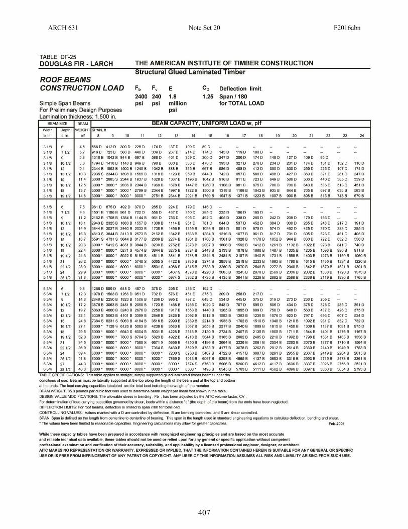
407
ARCH 631 Note Set 20 F2016abn
408
The self weight of the selection should be determined to compare to the assumption. Table
DF-25 indicates the self weight is 13 lb/ft, and that size at our span is controlled by deflection
(I for =L/180), but this chart is for simply supported beams and EI
wL
384
5 4
max .
The maximum deflection for a two span beam can be found with EI
wL
185
4
max , which is only
0.415x the deflection of a simply supported span.
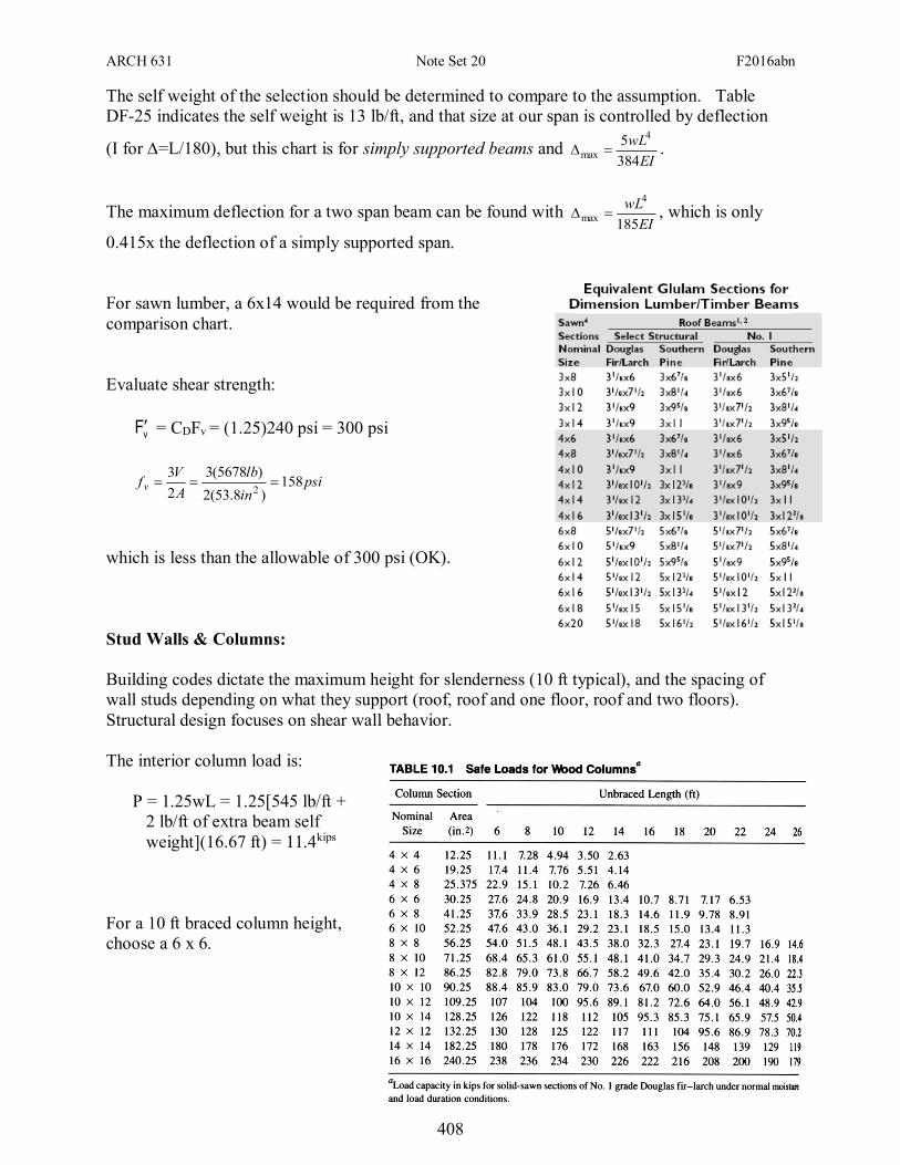
For sawn lumber, a 6x14 would be required from the
comparison chart.
Evaluate shear strength:
vF = CDFv = (1.25)240 psi = 300 psi
psiin
lb
A
Vf v 158
)8.53(2
)5678(3
2
32
which is less than the allowable of 300 psi (OK).
Stud Walls & Columns:
Building codes dictate the maximum height for slenderness (10 ft typical), and the spacing of
wall studs depending on what they support (roof, roof and one floor, roof and two floors).
Structural design focuses on shear wall behavior.
The interior column load is:
P = 1.25wL = 1.25[545 lb/ft +
2 lb/ft of extra beam self
weight](16.67 ft) = 11.4kips
For a 10 ft braced column height,
choose a 6 x 6.
ARCH 631 Note Set 20 F2016abn
409
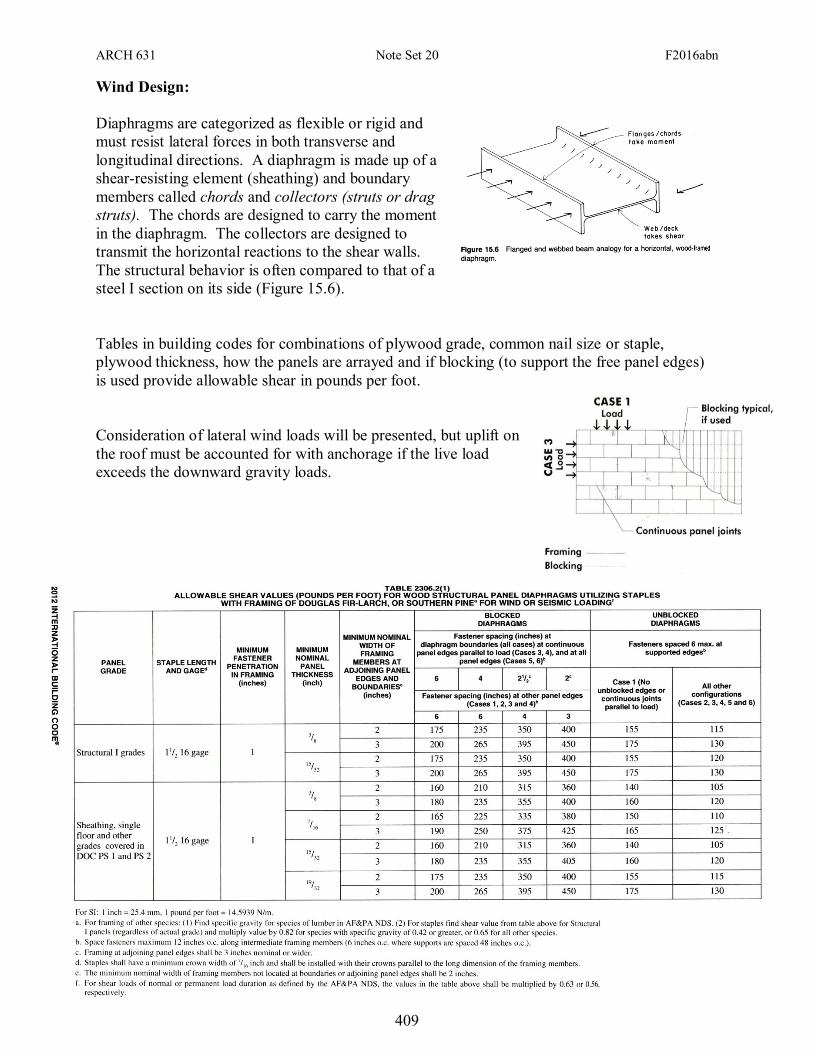
Wind Design:
Diaphragms are categorized as flexible or rigid and
must resist lateral forces in both transverse and
longitudinal directions. A diaphragm is made up of a
shear-resisting element (sheathing) and boundary
members called chords and collectors (struts or drag
struts). The chords are designed to carry the moment
in the diaphragm. The collectors are designed to
transmit the horizontal reactions to the shear walls.
The structural behavior is often compared to that of a
steel I section on its side (Figure 15.6).
Tables in building codes for combinations of plywood grade, common nail size or staple,
plywood thickness, how the panels are arrayed and if blocking (to support the free panel edges)
is used provide allowable shear in pounds per foot.
Consideration of lateral wind loads will be presented, but uplift on
the roof must be accounted for with anchorage if the live load
exceeds the downward gravity loads.
ARCH 631 Note Set 20 F2016abn
410
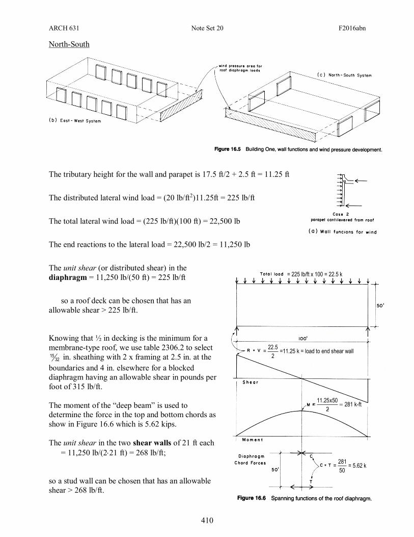
North-South
The tributary height for the wall and parapet is 17.5 ft/2 + 2.5 ft = 11.25 ft
The distributed lateral wind load = (20 lb/ft2)11.25ft = 225 lb/ft
The total lateral wind load = (225 lb/ft)(100 ft) = 22,500 lb
The end reactions to the lateral load = 22,500 lb/2 = 11,250 lb
The unit shear (or distributed shear) in the
diaphragm = 11,250 lb/(50 ft) = 225 lb/ft
so a roof deck can be chosen that has an
allowable shear > 225 lb/ft.
Knowing that ½ in decking is the minimum for a
membrane-type roof, we use table 2306.2 to select
3215 in. sheathing with 2 x framing at 2.5 in. at the
boundaries and 4 in. elsewhere for a blocked
diaphragm having an allowable shear in pounds per
foot of 315 lb/ft.
The moment of the “deep beam” is used to
determine the force in the top and bottom chords as
show in Figure 16.6 which is 5.62 kips.
The unit shear in the two shear walls of 21 ft each
= 11,250 lb/(221 ft) = 268 lb/ft;
so a stud wall can be chosen that has an allowable
shear > 268 lb/ft.
= 225 lb/ft x 100 = 22.5 k
=2
5.22=11.25 k = load to end shear wall
= 2
50x25.11281 k-ft
=50
281= 5.62 k
ARCH 631 Note Set 20 F2016abn
411
5.625 k
17 ft
0.3 k
10 at 1.9’ (1 bolts)
4.3 k
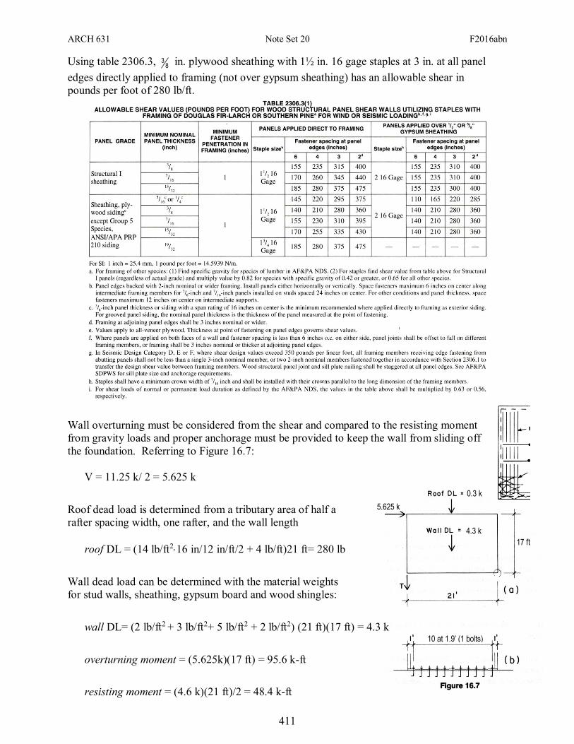
Using table 2306.3, 83 in. plywood sheathing with 1½ in. 16 gage staples at 3 in. at all panel
edges directly applied to framing (not over gypsum sheathing) has an allowable shear in
pounds per foot of 280 lb/ft.
Wall overturning must be considered from the shear and compared to the resisting moment
from gravity loads and proper anchorage must be provided to keep the wall from sliding off
the foundation. Referring to Figure 16.7:
V = 11.25 k/ 2 = 5.625 k
Roof dead load is determined from a tributary area of half a
rafter spacing width, one rafter, and the wall length
roof DL = (14 lb/ft216 in/12 in/ft/2 + 4 lb/ft)21 ft= 280 lb
Wall dead load can be determined with the material weights
for stud walls, sheathing, gypsum board and wood shingles:
wall DL= (2 lb/ft2 + 3 lb/ft2+ 5 lb/ft2 + 2 lb/ft2) (21 ft)(17 ft) = 4.3 k
overturning moment = (5.625k)(17 ft) = 95.6 k-ft
resisting moment = (4.6 k)(21 ft)/2 = 48.4 k-ft
ARCH 631 Note Set 20 F2016abn
412
The resisting moment is not enough to compensate for the overturning moment. We like the
factor of safety for overturning to be 1.5, and there is no safety in this case, which means we
must provide a tie down in tension (T). The L shape of the corner will help some resisting
overturning, as well as the glulam beam reaction.
For equilibrium of moments (positive = negative)
T(21ft) + 48.4 k-ft = (95.6 k-ft)1.5; Treq’d = 4.52 k
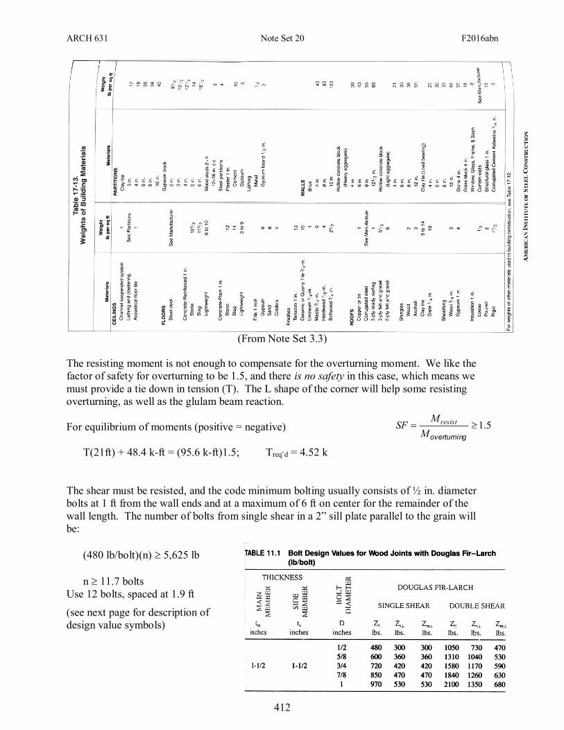
The shear must be resisted, and the code minimum bolting usually consists of ½ in. diameter
bolts at 1 ft from the wall ends and at a maximum of 6 ft on center for the remainder of the
wall length. The number of bolts from single shear in a 2” sill plate parallel to the grain will
be:
(480 lb/bolt)(n) 5,625 lb
n 11.7 bolts
Use 12 bolts, spaced at 1.9 ft
(see next page for description of
design value symbols)
5.1goverturninM
MSF resist
(From Note Set 3.3)
ARCH 631 Note Set 20 F2016abn
413
ZD = nominal lateral design value for single bolt in connection with all wood members loaded parallel to grain
Zs = nominal lateral design value for single bolt in wood-to-wood connection with main member loaded parallel to grain and side member loaded perpendicular to grain
Zm = nominal lateral design value for single bolt in wood-to-wood connection with main member loaded parallel to grain and side member loaded perpendicular to grain and side member loaded parallel to
grain
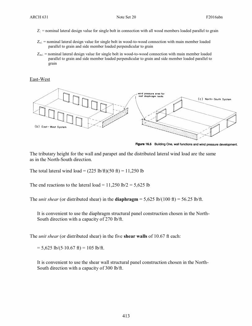
East-West
The tributary height for the wall and parapet and the distributed lateral wind load are the same
as in the North-South direction.
The total lateral wind load = (225 lb/ft)(50 ft) = 11,250 lb
The end reactions to the lateral load = 11,250 lb/2 = 5,625 lb
The unit shear (or distributed shear) in the diaphragm = 5,625 lb/(100 ft) = 56.25 lb/ft.
It is convenient to use the diaphragm structural panel construction chosen in the North-
South direction with a capacity of 270 lb/ft.
The unit shear (or distributed shear) in the five shear walls of 10.67 ft each:
= 5,625 lb/(510.67 ft) = 105 lb/ft.
It is convenient to use the shear wall structural panel construction chosen in the North-
South direction with a capacity of 300 lb/ft.