Embed Size (px)
Citation preview

Casing Design for Extreme Temperature
Matthías Matthíasson and Kristinn Ingason

July 3, 2007: Engine
Basic assumptions
The hole will be cased off down to the critical point
Bottom Hole Temperature max 550 C
Bottom Hole Pressure max 26,7 MPa
ASME and ASA codes or standards has to be “intertwine” into API standards
The well shall be “safe” in flowing and closed
conditions

July 3, 2007: Engine
Critical Point (CP)
CP represents the highest temperature and pressure at which the substance can exist as a vapour and liquid in equilibrium.
CP for water:
TC = 374 °C
PC = 22,1 MPaCP
July 3, 2007: Engine
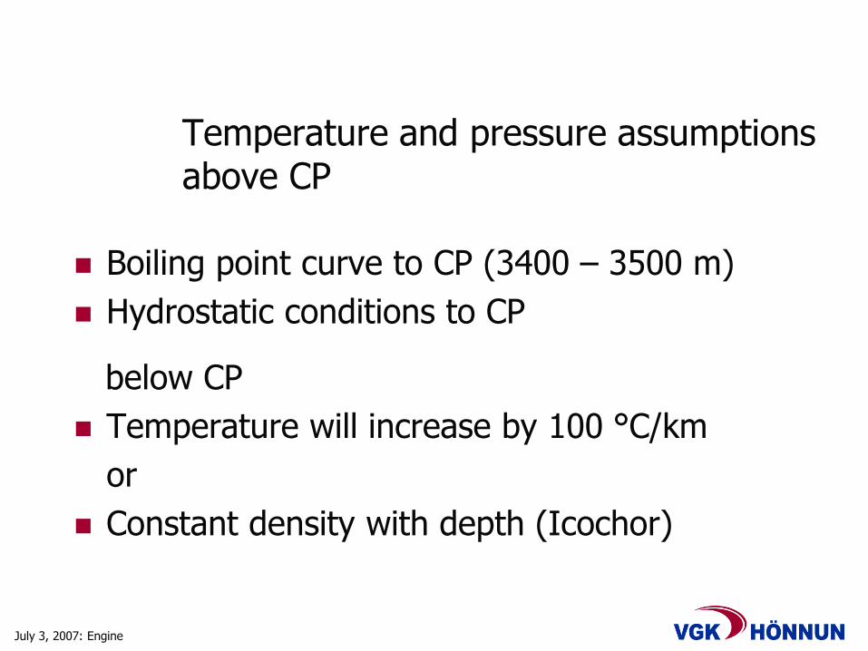
Temperature and pressure assumptionsabove CP
Boiling point curve to CP (3400 – 3500 m)
Hydrostatic conditions to CP
below CP
Temperature will increase by 100 °C/km
or
Constant density with depth (Icochor)

July 3, 2007: Engine
Reservoir temperature and pressureStatic and Flowing
18000
16000
14000
12000
10000
8000
6000
4000
2000
0
1000 2000 3000 4000 5000 6000 7000 8000
100 200 300 400 500 600 700 800 900 10001100
6000
5000
4000
3000
2000
1000
0
0 10 20 30 40 50 60
Boiling water
20°C water
Boiling water
De
pth
[m
/ fe
et]
Pressure [MPa / psi]
Temperature
Pressure
0 100 200 300 400 500 600
Temperature [°C / °F]
6000
5000
4000
3000
2000
1000
0
0 10 20 30 40 50 60
Flowing well 550°C, 25 MPa, 9" pipe
Flowing well, isochor, 9" pipe
Boiling water
20°C wate
De
pth
[m
]
Pressure [MPa]
Pressure Temperature
0 100 200 300 400 500 600
Temperature [°C]
July 3, 2007: Engine
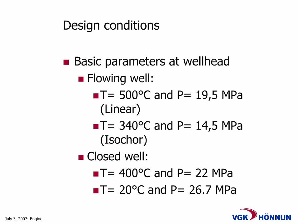
Design conditions
Basic parameters at wellhead
Flowing well:
T= 500°C and P= 19,5 MPa (Linear)
T= 340°C and P= 14,5 MPa (Isochor)
Closed well:
T= 400°C and P= 22 MPa
T= 20°C and P= 26.7 MPa
July 3, 2007: Engine
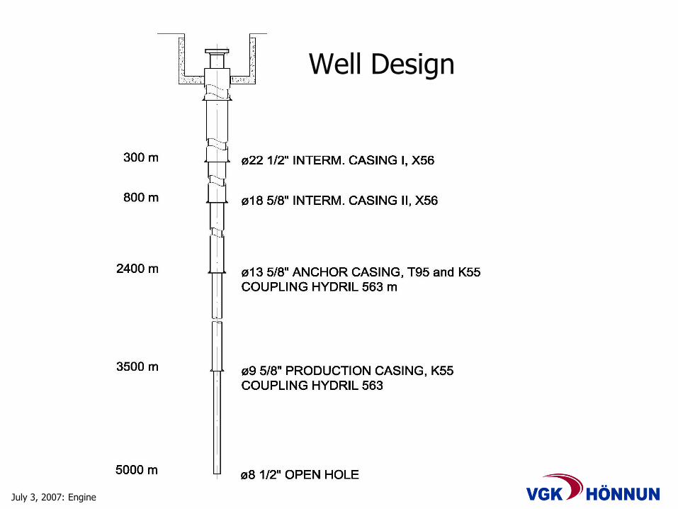
Well Design

July 3, 2007: Engine
Conclusions
Diameter: ø13 5/8”, 88,2 lbs/ft for top 300 m of anchor casing
ø13 3/8”, 72,0 lbs/ft for 300 to 2400 m of anchor casing
Ø9 5/8”, 53,5 lbs/ft production casing
Casing materials: T-95 type 1 and K-55 for anchor casing
K-55 for production casing
Casing connections: Hydril 563 (coupling and thread)
Wellhead flange: ø10” ANSI, Class 2500 (material group 1.9, ANSI B16.5)
Wellhead master vale: ø10” ANSI, Class 2500 (material group 1.9, ANSI B16.34)

July 3, 2007: Engine
Stress Calculations
axially σz; tangentially σt; radially r
,r
pm
zA
APt
m iP D
t2, r
mP
2,
Internal overpressure Pm (MPa)
Internal pipe area Ap, (mm2)
Cross-sectional area of pipe wall Ar (mm2)
Internal pipe diameter Di (mm)
Pipe wall thickness t (mm).

July 3, 2007: Engine
Stress Intensity
Permissible stress levels:
S1 = z - t ; S2 = t r ; S3 = r z
stress intensity S
S = max(S1,S2,S3)
Results of stress calculations
July 3, 2007: Engine
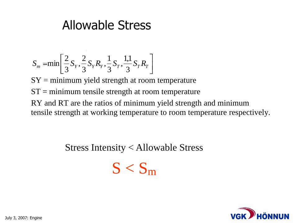
Allowable Stress
The respective design is acceptable provided
S < Sm, where
Sm is the allowable stress,
defined by the equation:
TTTYYYm RSSRSSS3
1,1,
3
1,
3
2,
3
2min
SY = minimum yield strength at room temperature
ST = minimum tensile strength at room temperature
RY and RT are the ratios of minimum yield strength and minimum
tensile strength at working temperature to room temperature respectively.
Material Max. permitted stress intensity at prevailing temp
20°C 340°C 400°C 500°C
K-55 Sm MPa 240.2 228,2 208,9 148,9
L-80 Sm MPa 240,2 221,0 199,3 156,1
T-95 Sm MPa 265,5 244,2 220,3 172,6
S < Sm
Stress Intensity < Allowable Stress
July 3, 2007: Engine
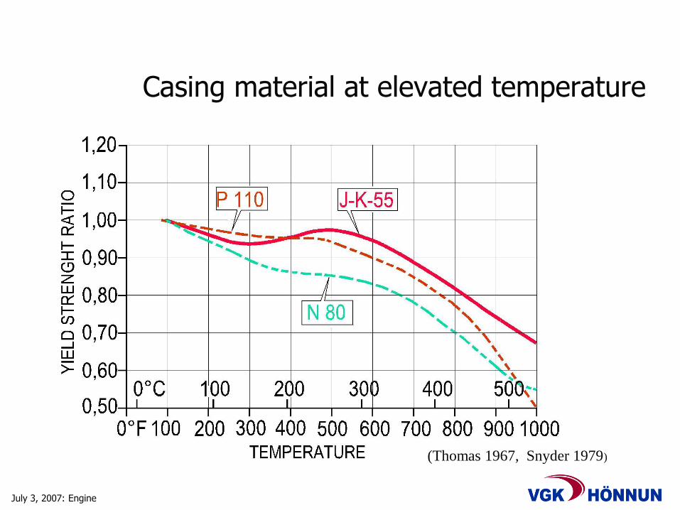
Casing material at elevated temperature
(Thomas 1967, Snyder 1979)
July 3, 2007: Engine
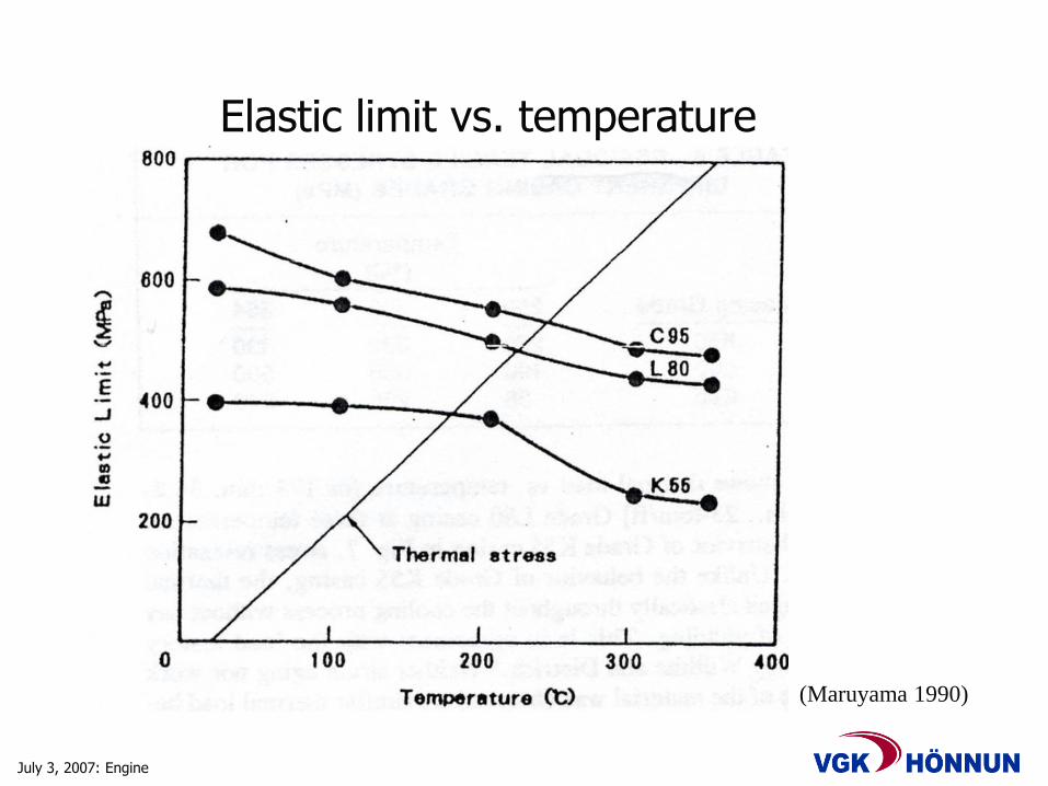
Elastic limit vs. temperature
(Maruyama 1990)
July 3, 2007: Engine
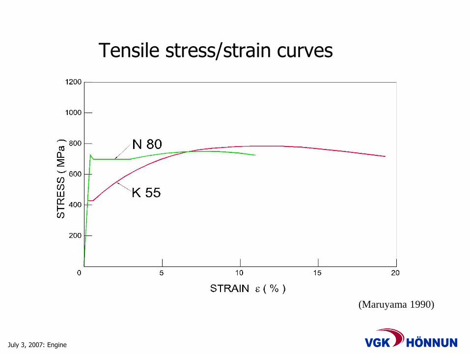
Tensile stress/strain curves
(Maruyama 1990)
July 3, 2007: Engine
0 100 200 300 400 500 600 700
0
50
100
150
200
250
300
350
400
450
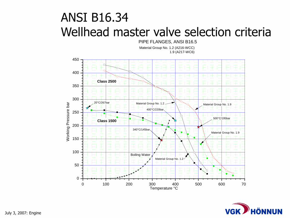
500°C/195bar
400°C/220bar
Material Group No. 1.2
Material Group No. 1.9
20°C/267bar
Class 2500
Material Group No. 1.2
Class 1500
Boiling Water
Wo
rkin
g P
ressu
re b
ar
Temperature °C
PIPE FLANGES, ANSI B16.5
Material Group No. 1.2 (A216-WCC)
1.9 (A217-WC6)
Material Group No. 1.9
340°C/145bar
ANSI B16.34Wellhead master valve selection criteria

July 3, 2007: Engine
HYDRIL connections, type 563
July 3, 2007: Engine
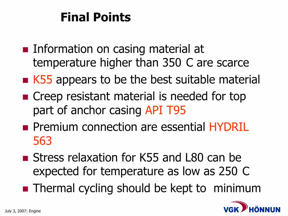
Final Points
Information on casing material at temperature higher than 350 C are scarce
K55 appears to be the best suitable material
Creep resistant material is needed for top part of anchor casing API T95
Premium connection are essential HYDRIL 563
Stress relaxation for K55 and L80 can be expected for temperature as low as 250 C
Thermal cycling should be kept to minimum
July 3, 2007: Engine
VGK-Hönnun hf.Grensásvegur 1, 108 Reykjavik, Tel: (+354) 422 3000
Web: www.vgkhonnun.is / E-mail: [email protected]