Embed Size (px)
Citation preview
Siemens FI 01 · 2017 US Edition
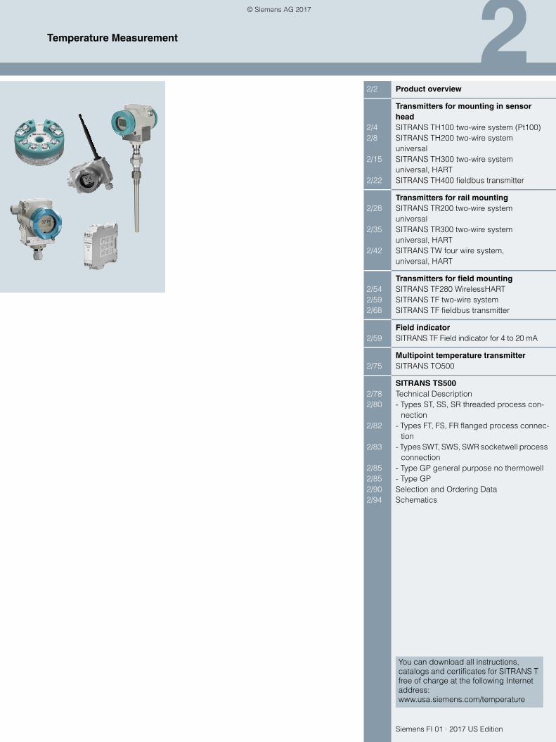
22/2 Product overview
Transmitters for mounting in sensor head
2/4 SITRANS TH100 two-wire system (Pt100)2/8 SITRANS TH200 two-wire system
universal2/15 SITRANS TH300 two-wire system
universal, HART2/22 SITRANS TH400 fieldbus transmitter
Transmitters for rail mounting2/28 SITRANS TR200 two-wire system
universal2/35 SITRANS TR300 two-wire system
universal, HART2/42 SITRANS TW four wire system,
universal, HART
Transmitters for field mounting2/54 SITRANS TF280 WirelessHART2/59 SITRANS TF two-wire system2/68 SITRANS TF fieldbus transmitter
Field indicator2/59 SITRANS TF Field indicator for 4 to 20 mA
Multipoint temperature transmitter 2/75 SITRANS TO500
SITRANS TS5002/78 Technical Description2/80 - Types ST, SS, SR threaded process con-
nection2/82 - Types FT, FS, FR flanged process connec-
tion2/83 - Types SWT, SWS, SWR socketwell process
connection2/85 - Type GP general purpose no thermowell2/85 - Type GP2/90 Selection and Ordering Data2/94 Schematics
You can download all instructions, catalogs and certificates for SITRANS T free of charge at the following Internet address: www.usa.siemens.com/temperature
Temperature Measurement
© Siemens AG 2017
2/2 Siemens FI 01 · 2017 US Edition
Temperature MeasurementProduct overview
2
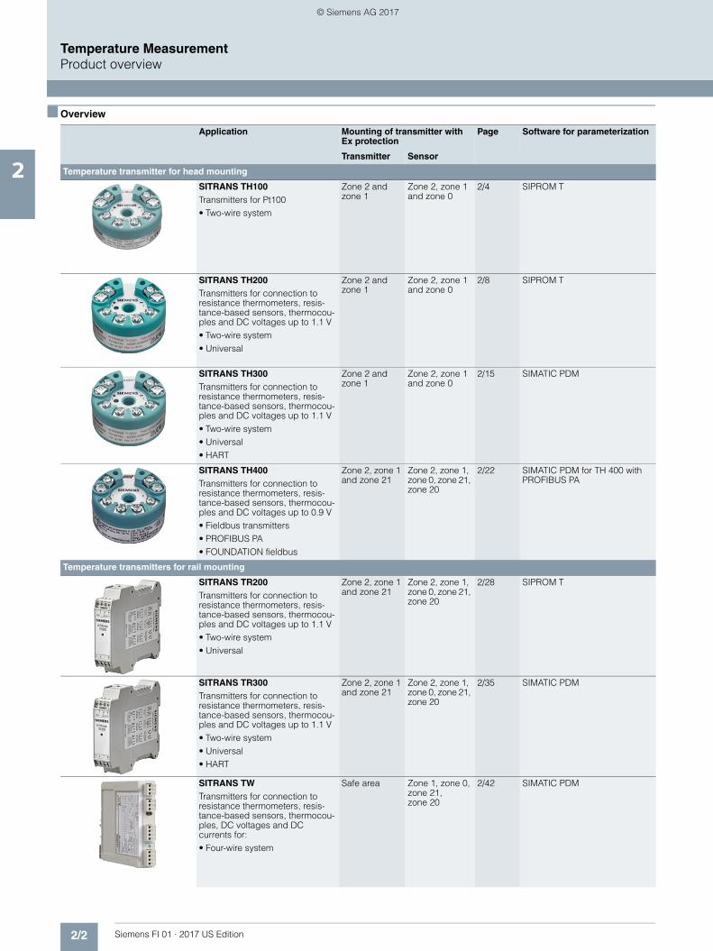
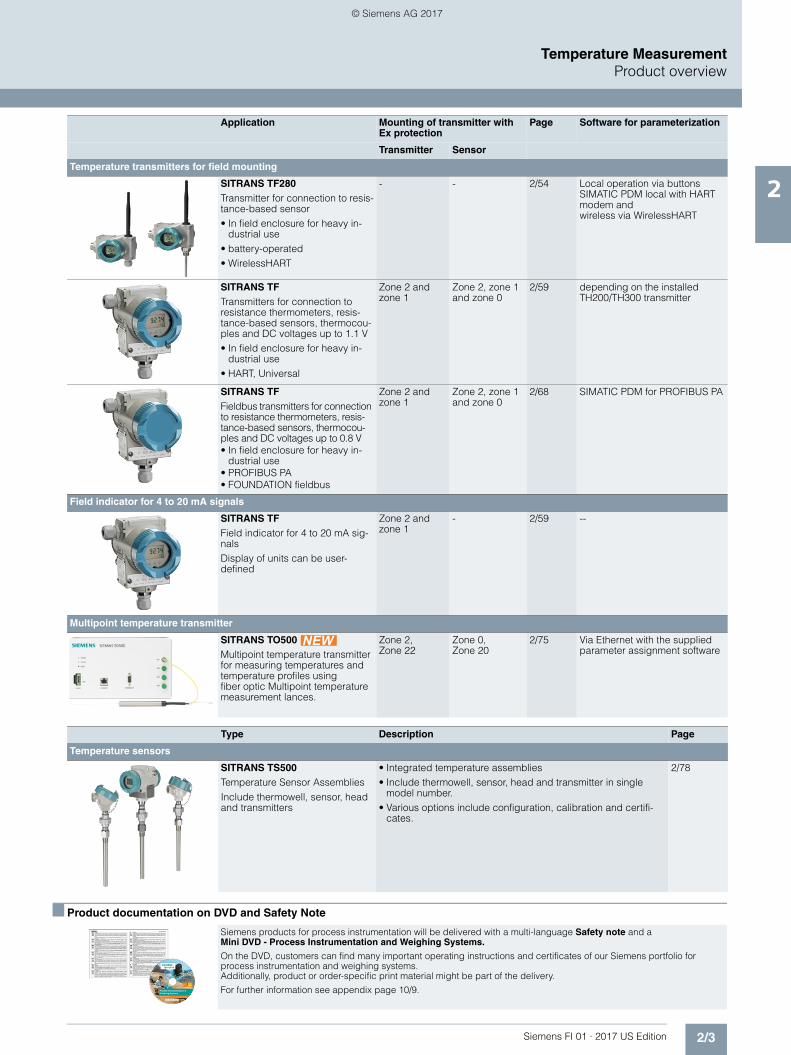
■ Overview
Application Mounting of transmitter with Ex protection
Page Software for parameterization
Transmitter Sensor
Temperature transmitter for head mounting
SITRANS TH100Transmitters for Pt100• Two-wire system
Zone 2 and zone 1
Zone 2, zone 1 and zone 0
2/4 SIPROM T
SITRANS TH200Transmitters for connection to resistance thermometers, resis-tance-based sensors, thermocou-ples and DC voltages up to 1.1 V• Two-wire system• Universal
Zone 2 and zone 1
Zone 2, zone 1 and zone 0
2/8 SIPROM T
SITRANS TH300Transmitters for connection to resistance thermometers, resis-tance-based sensors, thermocou-ples and DC voltages up to 1.1 V• Two-wire system• Universal• HART
Zone 2 and zone 1
Zone 2, zone 1 and zone 0
2/15 SIMATIC PDM
SITRANS TH400Transmitters for connection to resistance thermometers, resis-tance-based sensors, thermocou-ples and DC voltages up to 0.9 V• Fieldbus transmitters• PROFIBUS PA• FOUNDATION fieldbus
Zone 2, zone 1 and zone 21
Zone 2, zone 1, zone 0, zone 21, zone 20
2/22 SIMATIC PDM for TH 400 with PROFIBUS PA
Temperature transmitters for rail mounting
SITRANS TR200Transmitters for connection to resistance thermometers, resis-tance-based sensors, thermocou-ples and DC voltages up to 1.1 V• Two-wire system• Universal
Zone 2, zone 1 and zone 21
Zone 2, zone 1, zone 0, zone 21, zone 20
2/28 SIPROM T
SITRANS TR300Transmitters for connection to resistance thermometers, resis-tance-based sensors, thermocou-ples and DC voltages up to 1.1 V• Two-wire system• Universal• HART
Zone 2, zone 1 and zone 21
Zone 2, zone 1, zone 0, zone 21, zone 20
2/35 SIMATIC PDM
SITRANS TWTransmitters for connection to resistance thermometers, resis-tance-based sensors, thermocou-ples, DC voltages and DC currents for:• Four-wire system
Safe area Zone 1, zone 0, zone 21, zone 20
2/42 SIMATIC PDM
© Siemens AG 2017
2/3Siemens FI 01 · 2017 US Edition
Temperature MeasurementProduct overview
2
■ Product documentation on DVD and Safety Note
Temperature transmitters for field mounting
SITRANS TF280Transmitter for connection to resis-tance-based sensor• In field enclosure for heavy in-
dustrial use• battery-operated• WirelessHART
- - 2/54 Local operation via buttonsSIMATIC PDM local with HART modem and wireless via WirelessHART
SITRANS TFTransmitters for connection to resistance thermometers, resis-tance-based sensors, thermocou-ples and DC voltages up to 1.1 V• In field enclosure for heavy in-
dustrial use• HART, Universal
Zone 2 and zone 1
Zone 2, zone 1 and zone 0
2/59 depending on the installed TH200/TH300 transmitter
SITRANS TFFieldbus transmitters for connection to resistance thermometers, resis-tance-based sensors, thermocou-ples and DC voltages up to 0.8 V• In field enclosure for heavy in-
dustrial use• PROFIBUS PA• FOUNDATION fieldbus
Zone 2 and zone 1
Zone 2, zone 1 and zone 0
2/68 SIMATIC PDM for PROFIBUS PA
Field indicator for 4 to 20 mA signals
SITRANS TFField indicator for 4 to 20 mA sig-nals Display of units can be user-defined
Zone 2 and zone 1
- 2/59 --
Multipoint temperature transmitter
SITRANS TO500 Multipoint temperature transmitter for measuring temperatures and temperature profiles using fiber optic Multipoint temperature measurement lances.
Zone 2, Zone 22
Zone 0, Zone 20
2/75 Via Ethernet with the supplied parameter assignment software
Type Description Page
Temperature sensors
SITRANS TS500Temperature Sensor AssembliesInclude thermowell, sensor, head and transmitters
• Integrated temperature assemblies• Include thermowell, sensor, head and transmitter in single
model number. • Various options include configuration, calibration and certifi-
cates.
2/78
Siemens products for process instrumentation will be delivered with a multi-language Safety note and aMini DVD - Process Instrumentation and Weighing Systems.
On the DVD, customers can find many important operating instructions and certificates of our Siemens portfolio for process instrumentation and weighing systems.Additionally, product or order-specific print material might be part of the delivery.
For further information see appendix page 10/9.
Application Mounting of transmitter with Ex protection
Page Software for parameterization
Transmitter Sensor
© Siemens AG 2017
2/4 Siemens FI 01 · 2017 US Edition
Temperature MeasurementTransmitters for mounting in sensor head
SITRANS TH100 two-wire system (Pt100)
2
■ Overview
The SITRANS TH100 dispenses with electrical isolation and uni-versal sensor connection to provide a low-cost alternative for Pt100 measurements.
For the parameterization, the SIPROM T software is used in com-bination with the modem for SITRANS TH100/TH200.
Its extremely compact design makes the SITRANS TH100 ideal for the retrofitting of measuring points or for the use of analog transmitters.
The transmitter is available as a non-Ex version as well as for use in potentially explosive atmospheres.
■ Benefits
• Two-wire transmitter• Assembly in connection head type B (DIN 43729) or larger, or
on a standard DIN rail• Can be programmed, which means that the sensor connec-
tion, measuring range, etc. can also be programmed• Intrinsically-safe version for use in potentially explosive areas
■ Application
Used in conjunction with Pt100 resistance thermometers, theSITRANS TH100 transmitters are ideal for measuring tempera-tures in all industries. Due to its compact size it can be installedin the connection head type B (DIN 43729) or larger.
The output signal is a direct current from 4 to 20 mA that is pro-portional to the temperature.
Parameterization is implemented over the PC using the parame-terization software SIPROM T and the modem forSITRANS TH100/TH200. If you already have a "modem forSITRANS TK" (Article No. 7NG3190-6KB), you can continue us-ing this to parameterize the SITRANS TH100.
Transmitters of the "intrinsically-safe" type of protection can beinstalled within potentially explosive atmospheres. The devicescomply with the Directive 94/9/EC (ATEX), as well as FM andCSA regulations.
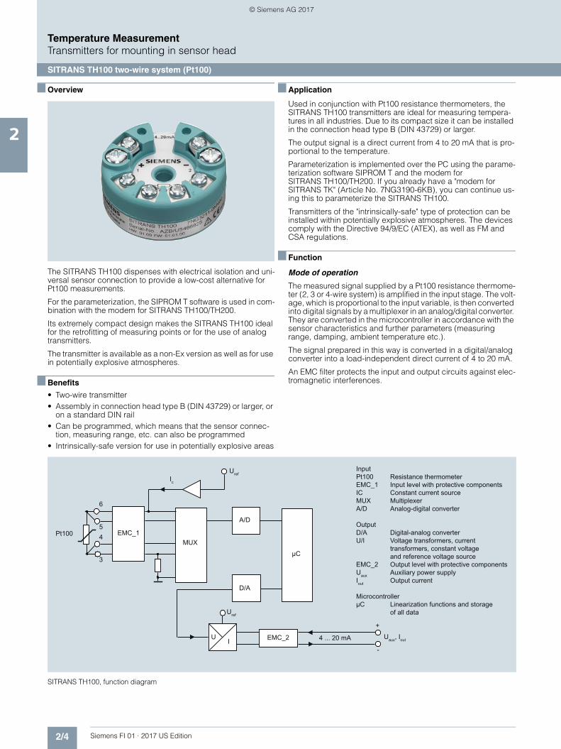
■ Function
Mode of operation
The measured signal supplied by a Pt100 resistance thermome-ter (2, 3 or 4-wire system) is amplified in the input stage. The volt-age, which is proportional to the input variable, is then converted into digital signals by a multiplexer in an analog/digital converter. They are converted in the microcontroller in accordance with the sensor characteristics and further parameters (measuringrange, damping, ambient temperature etc.).
The signal prepared in this way is converted in a digital/analogconverter into a load-independent direct current of 4 to 20 mA.
An EMC filter protects the input and output circuits against elec-tromagnetic interferences.
SITRANS TH100, function diagram
InputPt100 Resistance thermometerEMC_1 Input level with protective componentsIC Constant current sourceMUX MultiplexerA/D Analog-digital converter
OutputD/A Digital-analog converterU/I Voltage transformers, current
transformers, constant voltage and reference voltage source
EMC_2 Output level with protective componentsUaux Auxiliary power supplyIout Output current
MicrocontrollerμC Linearization functions and storage
of all data
A/D
D/A
Uaux, Iout
6
5
3
4 EMC_1Pt100MUX
μC
UI
Uref
EMC_2 4 ... 20 mA
UrefIc
+
-
© Siemens AG 2017
2/5Siemens FI 01 · 2017 US Edition
Temperature MeasurementTransmitters for mounting in sensor head
SITRANS TH100 two-wire system (Pt100)
2
■ Technical specificationsInput
Resistance thermometer
Measured variable Temperature
Sensor type PT100 to IEC 60751
Characteristic curve Temperature-linear
Type of connection 2-, 3- or 4-wire circuit
Resolution 14 bit
Measuring accuracy• Span <250 °C (450 °F) < 0.25 °C (0.45 °F)• Span >250 °C (450 °F) < 0.1 % of span
Repeatability < 0.1 °C (0.18 °F)
Measuring current approx. 0.4 mA
Measuring cycle < 0.7 s
Measuring range -200 ... +850 °C-328 ... +1562 °F)
Measuring span 25 ... 1050 °C (77 ... 1922 °F)
Unit °C or °F
Offset programmable:-100 ... +100 °C (-180 ... +180 °F)
Line resistance Max. 20 Ω (total from feeder and return conductor)
Noise rejection 50 and 60 Hz
Output
Output signal 4 ... 20 mA, two-wire
Auxiliary power 8.5 ... 36 V DC (30 V for Ex ia and ib; 32 V for Ex nL/ic; 35 V for Ex nA)
Max. load (Uaux - 8.5 V)/0.023 A
Overrange 3.6 ... 23 mA, infinitely adjustable (default range: 3.84 ... 20.5 mA)
Error signal (following sensor fault) (conforming to NE43)
3.6 ... 23 mA, infinitely adjustable (default range: 3.6 mA or 22.8 mA)
Damping time 0 ... 30 s (default value: 0 s)
Protection Against reversed polarity
Resolution 12 bit
Accuracy at 23 °C (73.4 °F) < 0.1 % of span
Temperature effect < 0.1 %/10 °C (0.1 %/18 °F)
Effect of auxiliary power < 0.01 % of span/V
Effect of load impedance < 0.025 % of max. span/100 Ω
Long-term drift • < 0.025 % of the max. span in the first month
• < 0.035 % of the max. span after one year
• < 0.05 % of the max. span after 5 years
Ambient conditions
Ambient temperature range -40 ... +85 °C (-40 ... +185 °F)
Storage temperature range -40 ... +85 °C (-40 ... +185 °F)
Relative humidity 98 %, with condensation
Electromagnetic compatibility According to EN 61326 and NAMUR NE21
Construction
Weight 50 g
Dimensions See dimensional drawing
Material Molded plastic
Cross-section of cables Max. 2.5 mm2 (AWG 13)
Degree of protection to IEC 60529
• Enclosure IP40
• Terminals IP00
Certificates and approvalsExplosion protection ATEXEC type test certificate PTB 05 ATEX 2049X• "Intrinsic gas safety" type of pro-
tectionII 1 G Ex ia IIC T6/T4II (1) 2 G Ex ib [ia Ga] IIC T6/T4 GbII (1) 3 G Ex ic [ia Ga] IIC T6/T4 GcII 3 G Ex ic IIC T6/T4 Gc
• "Non-sparking" type of protection II 3 G Ex nA IIC T6/T4 GcII 3 G Ex nA[ic] IIC T6/T4 Gc
• "Intrinsic dust safety" type of pro-tection
II 1 D Ex ia IIIC T115 °C Da
Explosion protection FM for USA and Canada (cFMUS)• FM approval PID 3024169• Degree of protection IS Cl I, II, III, Div 1, GP ABCDEFG
T4/T5/T6Cl I, ZN 0,1 AEx ia IIC T4/T5/T6NI Cl I, II, III, Div 2, GP ABCDFG T4/T5/T6Cl I, ZN 2, NI IIC T4/T5/T6
Other certificates GOST, NEPSI, PESO
Software requirements for SIPROM TPC operating system Windows ME, 2000, XP, Win 7 and
Win 8; can also be used in con-nection with RS 232 modem under Windows 95, 98 and 98SE
© Siemens AG 2017

2/6 Siemens FI 01 · 2017 US Edition
Temperature MeasurementTransmitters for mounting in sensor head
SITRANS TH100 two-wire system (Pt100)
2
■ Selection and Ordering data Article No.
Supply units see Chapter "Supplementary Components".Ordering example7NG3211-0NN00-Z Y01+Y23+U03Y01: -10 ... +100 °CY23: TICA1234HEATFactory setting:• Pt100 (IEC 751) with 3-wire circuit• Measuring range: 0 … 100 °C (32 … 212 °C)• Error signal in the event of sensor breakage: 22.8 mA• Sensor offset: 0 C (0 °F)• Damping 0.0 s
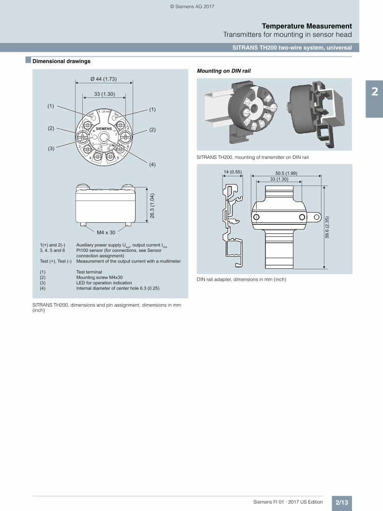
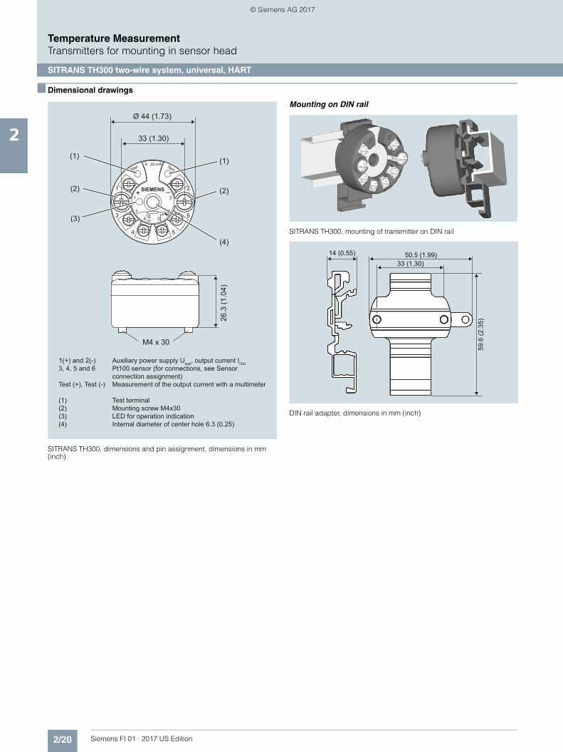
■ Dimensional drawings
SITRANS TH100, dimensions in mm (inch)
Mounting on DIN rail
SITRANS TH100, mounting of transmitter on DIN rail
DIN rail adaptor, dimensions in mm (inch)
SITRANS TH100 temperature transmitters for Pt100for installation in connection head, type B (DIN 43729), two-wire system, 4 ... 20 mA, programmable, without electrical isolation
• Without explosion protection 7NG3211-0NN00
• With explosion protection "Intrinsic safety" type of protection and for zone 2- to ATEX 7NG3211-0AN00- to FM (cFMUS) 7NG3211-0BN00
Further designs Order code
Add "-Z" to Article No. and specify Order code(s)
Test report (5 measuring points) C11
Customer-specific programmingAdd "-Z" to Article No. and specify Order code(s)
Measuring range to be setSpecify in plain text (max. 5 digits):Y01: ... to ... °C, °F
Y011)
1) For customer-specific programming for RTD and TC, the start value and the end value of the required measuring span must be specified here.
Measuring point no. (TAG), max. 8 characters Y172)
2) For this selection, Y01 or Y09 must also be selected.
Measuring point descriptor, max. 16 charac-ters
Y232)
Pt100 (IEC) 2-wire, RL = 0 Ω U023)
3) For this selection, Y01 must also be selected.
Pt100 (IEC) 3-wire U033)
Pt100 (IEC) 4-wire U043)
Special differing customer-specific program-ming, specify in plain text
Y094)
4) For customer-specific programming, for example mV and ohm, the start value and the end value of the required measuring span and the unit must be entered here.
Fail-safe value 3.6 mA (instead of 22,8 mA) U362)
Accessories Article No.
Modem for SITRANS TH100, TH200, TR200 and TF with TH200 incl. SIPROM T parameteri-zation software With USB connection
7NG3092-8KU
MiniDVD for temperature measuring instru-ments
A5E00364512
With documentation in German, English, French, Spanish, Italian, Portuguese and SIPROM T parameterization software
DIN rail adapters for head transmitters(Quantity delivered: 5 units)
7NG3092-8KA
Connecting cable4-wire, 150 mm, for sensor connections when using head transmitters in the high hinged cover (set with 5 units)
7NG3092-8KC
1 2
3 6
4 3-W 5
1 SIEMENS
4..20mA
+ –
3
4 5
2
6
1(+) and 2(-) Auxiliary power supply Uaux, output current IOut3, 4, 5 and 6 Pt100 sensor (for connection, see sensor connection assignment)
Internal diameter Center hole 6.3 (0.25)
Mounting screw M4x25
20.8
(0.8
2)
33 (1.3)
44 (1.73)
50.5 (1.99)
59.6
(2.3
5)
33 (1.30)14 (0.55)
© Siemens AG 2017

2/7Siemens FI 01 · 2017 US Edition
Temperature MeasurementTransmitters for mounting in sensor head
SITRANS TH100 two-wire system (Pt100)
2
■ Schematics
SITRANS TH100, sensor connection assignment
-+
1 2
6
5
1 SIEMENS
4..20mA
+ – 2
6
3 6
4 3-W 53
4 5
63 6
4 3-W 53
4 5
6
3 6
4 3-W 53
4 5
6
Four-wire system
Three-wire systemTwo-wire system (parameterizable line
resistance)
Connection of auxiliary power supply (Uaux)
power supply (Uaux)
Pt100Pt100
Pt100
Uaux
© Siemens AG 2017

2/8 Siemens FI 01 · 2017 US Edition
Temperature MeasurementTransmitters for mounting in sensor head
SITRANS TH200 two-wire system, universal
2
■ Overview
Ultra flexible - with the universal SITRANS TH200 transmitter• Two-wire devices for 4 to 20 mA• Mounting in the connection head of the temperature sensor• Universal input for virtually any type of temperature sensor• Configurable over PC
■ Benefits
• Compact design• Flexible mounting and center hole allow you to select your pre-
ferred type of installation• Electrically isolated• Test sockets for multimeters• Diagnostics LED (green/red)• Sensor monitoring
open circuits and short-circuits• Self-monitoring• Configuration status stored in EEPROM• SIL2 (with Order Code C20), SIL2/3 (with C23)• Expanded diagnostic functions, such as slave pointer, operat-
ing hours counter, etc.• Special characteristic• Electromagnetic compatibility to EN 61326 and NE21
■ Application
SITRANS TH200 transmitters can be used in all industrial sec-tors. Due to their compact size they can be installed in the con-nection head type B (DIN 43729) or larger. The following sen-sors/signal sources can be connected over their universal input module:• Resistance thermometers (2, 3 or 4-wire system)• Thermocouples• Resistance-based sensors and DC voltage sources
The output signal is a direct current from 4 to 20 mA in accor-dance with the sensor characteristic.
Transmitters of the "intrinsically safe" type of protection can be in-stalled within potentially explosive atmospheres. The devices comply with the Directive 94/9/EC (ATEX), as well as FM and CSA regulations.
■ Function
The SITRANS TH200 is configured over a PC. A USB or RS 232 modem is linked to the output terminals for this purpose. The configuration data can now be edited using the SIPROM T soft-ware tool. The configuration data are then permanently stored in the non-volatile memory (EEPROM).
Once the sensors and power supply have been correctly con-nected, the transmitter outputs a temperature-linear output sig-nal and the diagnostics LED displays a green light. In the case of a sensor short-circuit, the LED flashes red, an internal device fault is indicated by a steady red light.
The test socket can be used to connect an ammeter at any time for monitoring purposes and plausibility checks. The output cur-rent can be read without any interruption, or even without open-ing the current loop.
SITRANS TH200 function diagram
InputA/D Analog-digital converterSensors Resistance thermometer, thermocouple, resistance-based sensor, mV sensorμC1 Microcontroller, secondary circuit
OutputμC2 Microcontroller, primary circuitD/A Digital-analog converterUaux Auxiliary power supplyIout Output current
(1) Electrically isolated(2) LED
TC/RTD sensor
(2)
+1
-2(1)
μC1 μC2
Test
4 ... 20 mA Uaux, Iout
SITRANS TH200/TH300
DA
AD
© Siemens AG 2017

2/9Siemens FI 01 · 2017 US Edition
Temperature MeasurementTransmitters for mounting in sensor head
SITRANS TH200 two-wire system, universal
2
■ Technical specifications
Input
Resistance thermometer
Measured variable Temperature
Sensor type
• to IEC 60751 Pt25 … Pt1000
• To JIS C 1604; a = 0.00392 K-1 Pt25 … Pt1000
• to IEC 60751 Ni25 … Ni1000
• Special type over special characteristic (max. 30 points)
Sensor factor 0.25 ... 10 (adaptation of the basic type, e.g. Pt100 to version Pt25 ... 1000)
Units °C or °F
Connection
• Standard connection 1 resistance thermometer (RTD) in 2-wire, 3-wire or 4-wire system
• Generation of average value 2 identical resistance thermome-ters in 2-wire system for genera-tion of average temperature
• Generation of difference 2 identical resistance thermome-ters (RTD) in 2-wire system (RTD 1 – RTD 2 or RTD 2 – RTD 1)
Interface
• Two-wire system Parameterizable line resistance ≤ 100 Ω (loop resistance)
• Three-wire system No balancing required
• Four-wire system No balancing required
Sensor current ≤ 0.45 mA
Response time ≤ 250 ms for 1 sensor with open-circuit monitoring
Open-circuit monitoring Always active (cannot be dis-abled)
Short-circuit monitoring can be switched on/off (default value: ON)
Measuring range parameterizable (see table "Digi-tal measuring errors")
Min. measured span 10 °C (18 °F)
Characteristic curve Temperature-linear or special characteristic
Resistance-based sensors
Measured variable Actual resistance
Sensor type Resistance-based, potentiome-ters
Units Ω
Connection
• Normal connection 1 resistance-based sensor (R) in 2-wire, 3-wire or 4-wire system
• Generation of average value 2 resistance-based sensors in 2-wire system for generation of average value
• Generation of difference 2 resistance thermometers in 2-wire system (R1 – R2 or R2 – R1)
Interface
• Two-wire system Parameterizable line resistance ≤ 100 Ω (loop resistance)
• Three-wire system No balancing required
• Four-wire system No balancing required
Sensor current ≤ 0.45 mA
Response time ≤ 250 ms for 1 sensor with open-circuit monitoring
Open-circuit monitoring Always active (cannot be dis-abled)
Short-circuit monitoring can be switched on/off (default value: OFF)
Measuring range parameterizable max. 0 ... 2200 Ω (see table "Digital measuring errors")
Min. measured span 5 Ω ... 25 Ω (see Table "Digital measuring errors")
Characteristic curve Resistance-linear or special char-acteristic
Thermocouples
Measured variable Temperature
Sensor type (thermocouples)
• Type B Pt30Rh-Pt6Rh to DIN IEC 584• Type C W5 %-Re acc. to ASTM 988• Type D W3 %-Re acc. to ASTM 988
• Type E NiCr-CuNi to DIN IEC 584• Type J Fe-CuNi to DIN IEC 584• Type K NiCr-Ni to DIN IEC 584
• Type L Fe-CuNi to DIN 43710• Type N NiCrSi-NiSi to DIN IEC 584• Type R Pt13Rh-Pt to DIN IEC 584
• Type S Pt10Rh-Pt to DIN IEC 584• Type T Cu-CuNi to DIN IEC 584• Type U Cu-CuNi to DIN 43710
Units °C or °F
Connection
• Standard connection 1 thermocouple (TC)
• Generation of average value 2 thermocouples (TC)
• Generation of difference 2 thermocouples (TC) (TC1 – TC2 or TC2 – TC1)
Response time ≤ 250 ms for 1 sensor with open-circuit monitoring
Open-circuit monitoring Can be switched off
Cold junction compensation
• Internal With integrated Pt100 resistance thermometer
• External With external Pt100 IEC 60571 (2-wire or 3-wire connection)
• External fixed Cold junction temperature can be set as fixed value
Measuring range Parameterizable (see table "Digi-tal measuring errors")
Min. measured span Min. 40 ... 100 °C (72 ... 180 °F) (see table "Digital measuring errors")
Characteristic curve Temperature-linear or special characteristic
mV sensor
Measured variable DC voltage
Sensor type DC voltage source (DC voltage source possible over an exter-nally connected resistor)
Units mV
Response time ≤ 250 ms for 1 sensor with open-circuit monitoring
Open-circuit monitoring Can be switched off
Measuring range -10 ... +70 mV-100 … +1100 mV
© Siemens AG 2017
2/10 Siemens FI 01 · 2017 US Edition
Temperature MeasurementTransmitters for mounting in sensor head
SITRANS TH200 two-wire system, universal
2
Factory setting: • Pt100 (IEC 751) with 3-wire circuit• Measuring range: 0 ... 100 °C (32 ... 212 °F)• Fault current: 22.8 mA• Sensor offset: 0 °C (0 °F)• Damping 0.0 s
Min. measured span 2 mV or 20 mV
Overload capability of the input -1.5 ... +3.5 V DC
Input resistance ≥ 1 MΩ
Characteristic curve Voltage-linear or special charac-teristic
Output
Output signal 4 ... 20 mA, 2-wire
Auxiliary power 11 ... 35 V DC ((to 30 V for Ex ia and ib; to 32 V for Ex nA / nL / ic)
Max. load (Uaux – 11 V)/0.023 A
Overrange 3.6 ... 23 mA, infinitely adjustable (default range: 3.80 mA ... 20.5 mA)
Error signal (e.g. following sensor fault) (conforming to NE43)
3.6 ... 23 mA, infinitely adjustable (default value: 22.8 mA)
Sample cycle 0.25 s nominal
Damping Software filter 1st order 0 ... 30 s (parameterizable)
Protection Against reversed polarity
Electrically isolated Input against output (1 kVeff)
Measuring accuracy
Digital measuring errors See table "Digital measuring errors"
Reference conditions
• Auxiliary power 24 V ± 1 %
• Load 500 Ω
• Ambient temperature 23 °C
• Warming-up time > 5 min
Error in the analog output (digi-tal/analog converter)
< 0.025 % of span
Error due to internal cold junction < 0.5 °C (0.9 °F)
Influence of ambient temperature
• Analog measuring error 0.02 % of span/10°C (18 °F)
• Digital measuring errors
- with resistance thermometers 0.06 °C (0.11 °F)/10°C (18 °F)
- with thermocouples 0.6 °C (1.1 °F)/10°C (18 °F)
Auxiliary power effect < 0.001 % of span/V
Effect of load impedance < 0.002 % of span/100 Ω
Long-term drift
• In the first month • < 0.02 % of span
• After one year • < 0.2 % of span
• After 5 years • < 0.3 % of span
Conditions of use
Ambient conditions
Ambient temperature range -40 ... +85 °C (-40 ... +185 °F)
Storage temperature range -40 ... +85 °C (-40 ... +185 °F)
Relative humidity < 98 %, with condensation
Electromagnetic compatibility acc. to EN 61326 and NE21
Construction
Material Molded plastic
Weight 50 g (0.11 lb)
Dimensions See "Dimensional drawings"
Cross-section of cables Max. 2.5 mm² (AWG 13)
Degree of protection to IEC 60529
• Enclosure IP40
• Terminals IP00
Certificates and approvals
Explosion protection ATEX
EC type test certificate PTB 05 ATEX 2040X
• "Intrinsic safety" type of protection II 1 G Ex ia IIC T6/T4II 2 (1) G Ex ia/ib IIC T6/T4II 3(1) G Ex ia/ic IIC T6/T4II 1D Ex iaD 20 T115 °C
• "Operating equipment that is non-ignitable and has limited energy" type of protection
II 3 G Ex nL IIC T6/T4II 3 G Ex nA IIC T6/T4
Explosion protection: FM for USA
• FM approval FM 3024169
• Degree of protection IS / Cl I, II, III / Div 1 / GP ABC-DEFG T6, T5, T4Cl I / ZN 0 / AEx ia IIC T6, T5, T4NI / Cl I / Div 2 / GP ABCDFG T6, T5, T4NI / Cl I / ZN 2 / IIC T6, T5, T4
Explosion protection to FM for Can-ada (cFMUS)
• FM approval FM 3024169C
• Degree of protection IS / Cl I, II, III / Div 1/ GP ABC-DEFG T6, T5, T4NI / Cl I / DIV 2 / GP ABCD T6, T5, T4NIFW / Cl I, II, III / DIV 2 / GP ABCDFG T6, T5, T4DIP / Cl II, III / Div 2 / GP FG T6, T5, T4Cl I / ZN 0 / Ex ia IIC T6, T5, T4Cl I / ZN 2 / Ex nA nL IIC T6, T5, T4
Other certificates GOST, NEPSI, PESO, IEC, EXPOLABS
Software requirements for SIPROM T
PC operating system Windows ME, 2000, XP, Win 7 and Win 8; can also be used in con-nection with RS 232 modem under Windows 95, 98 and 98SE
© Siemens AG 2017

2/11Siemens FI 01 · 2017 US Edition
Temperature MeasurementTransmitters for mounting in sensor head
SITRANS TH200 two-wire system, universal
2
Digital measuring errors
Resistance thermometer
Resistance-based sensors
Thermocouples
1) The digital accuracy in the range 0 to 300 °C (32 to 572 °F) is 3 °C (5.4 °F).2) The digital accuracy in the range 1750 to 2300 °C (3182 to 4172 °F) is 2 °C
(3.6 °F).
mV sensor
The digital accuracy is the accuracy after the analog/digital con-version including linearization and calculation of the measured value.
An additional error is generated in the output current 4 to 20 mA as a result of the digital/analog conversion of 0.025 % of the set span (digital-analog error).
The total error under reference conditions at the analog output is the sum from the digital error and the digital-analog error (poss. with the addition of cold junction errors in the case of thermocou-ple measurements).
Input Measuring range Min. mea-sured span
Digital accuracy
°C / (°F) °C (°F) °C (°F)
to IEC 60751
Pt25 -200 ... +850 (-328 ... +1562)
10 (18) 0.3 (0.54)
Pt50 -200 ... +850 (-328 ... +1562)
10 (18) 0.15 (0.27)
Pt100 ... Pt200 -200 ... +850 (-328 ... +1562)
10 (18) 0.1 (0.18)
Pt500 -200 ... +850 (-328 ... +1562)
10 (18) 0.15 (0.27)
Pt1000 -200 ... +350 (-328 ... +662)
10 (18) 0.15 (0.27)
to JIS C1604-81
Pt25 -200 ... +649 (-328 ... +1200)
10 (18) 0.3 (0.54)
Pt50 -200 ... +649 (-328 ... +1200)
10 (18) 0.15 (0.27)
Pt100 ... Pt200 -200 ... +649 (-328 ... +1200)
10 (18) 0.1 (0.18)
Pt500 -200 ... +649 (-328 ... +1200)
10 (18) 0.15 (0.27)
Pt1000 -200 ... +350 (-328 ... +662)
10 (18) 0.15 (0.27)
Ni 25 ... Ni1000 -60 ... +250 (-76 ... +482)
10 (18) 0.1 (0.18)
Input Measuring range Min. mea-sured span
Digital accuracy
Ω Ω Ω
Resistance 0 ... 390 5 0,05
Resistance 0 ... 2200 25 0,25
Input Measuring range Min. mea-sured span
Digital accu-racy
°C/(°F) °C (°F) °C (°F)
Type B 0 ... 1820 (32 ... 3308)
100 (180) 21) (3.60)1)
Type C (W5) 0 ... 2300 (32 ... 4172)
100 (180) 2 (3.60)
Type D (W3) 0 ... 2300 (32 ... 4172)
100 (180) 12) (1.80)2)
Type E -200 ... +1000 (-328 ... +1832)
50 (90) 1 (1.80)
Type J -210 ... +1200 (-346 ... +2192)
50 (90) 1 (1.80)
Type K -230 ... +1370 (-382 ... +2498)
50 (90) 1 (1.80)
Type L -200 ... +900 (-328 ... +1652)
50 (90) 1 (1.80)
Type N -200 ... +1300 (-328 ... +2372)
50 (90) 1 (1.80)
Type R -50 ... +1760 (-58 ... +3200)
100 (180) 2 (3.60)
Type S -50 ... +1760 (-58 ... +3200)
100 (180) 2 (3.60)
Type T -200 ... +400 (-328 ... +752)
40 (72) 1 (1.80)
Type U -200 ... +600 (-328 ... +1112)
50 (90) 2 (3.60)
Input Measuring range
Min. measured span
Digital accuracy
mV mV μV
mV sensor -10 ... +70 2 40
mV sensor -100 ... +1100 20 400
© Siemens AG 2017

2/12 Siemens FI 01 · 2017 US Edition
Temperature MeasurementTransmitters for mounting in sensor head
SITRANS TH200 two-wire system, universal
2
■ Selection and Ordering data Article No.
Supply units see Chapter "Supplementary Components".
Ordering example 1:
7NG3211-1NN00-Z Y01+Y17+U03Y01: -10 ... +100 °CY17: TICA123
Ordering example 2:
7NG3211-1NN00-Z Y01+Y23+U25Y01: -10 ... +100 °CY23: TICA1234HEAT
Factory setting: • Pt100 (IEC 751) with 3-wire circuit• Measuring range: 0 … 100 °C (32 … 212 °F)• Fault current: 22.8 mA• Sensor offset: 0 °C (0 °F)• Damping 0.0 s
Temperature transmitter SITRANS TH200
for installation in connection head, type B(DIN 43729), two-wire system, 4 ... 20 mA,programmable, with electrical isolation
• Without explosion protection 7NG3211-1NN00
• With explosion protection
- to ATEX 7NG3211-1AN00
- to FM (cFMUS) 7NG3211-1BN00
Further designs Order code
Add "-Z" to Article No. and specify Order code(s)
With test protocol (5 measuring points) C11
Functional safety SIL2 C20
Functional safety SIL2/3 C23
Customer-specific programmingAdd "-Z" to Article No. and specify Order code(s)
Measuring range to be setSpecify in plain text (max. 5 digits):Y01: ... to ... °C, °F
Y011)
Measuring point no. (TAG), max. 8 characters Y172)
Measuring point descriptor, max. 16 charac-ters
Y232)
Measuring point message, max. 32 characters Y242)
Pt100 (IEC) 2-wire, RL = 0 Ω U023)
Pt100 (IEC) 3-wire U033)
Pt100 (IEC) 4-wire U043)
Thermocouple type B U203)4)
Thermocouple type C (W5) U213)4)
Thermocouple type D (W3) U223)4)
Thermocouple type E U233)4)
Thermocouple type J U243)4)
Thermocouple type K U253)4)
Thermocouple type L U263)4)
Thermocouple type N U273)4)
Thermocouple type R U283)4)
Thermocouple type S U293)4)
Thermocouple type T U303)4)
Thermocouple type U U313)4)
With TC: CJC external (Pt100, 3-wire) U41
With TC: CJC external with fixed value, specify in plain text
Y50
Special differing customer-specific program-ming, specify in plain text
Y095)
Fail-safe value 3.6 mA (instead of 22,8 mA) U362)
Cable extension Transmitter with installed cable extension 200 mm (7.81 inch), for Pt100 in four-wire system
W01
Accessories Article No.
Modem for SITRANS TH100, TH200, TR200 and TF with TH200 incl. SIPROM T parameteri-zation softwareWith USB connection
7NG3092-8KU
MiniDVD for temperature measuring instru-mentsWith documentation in German, English, French, Spanish, Italian, Portuguese and SIPROM T parameterization software
A5E00364512
DIN rail adapters for head transmitters(Quantity delivered: 5 units)
7NG3092-8KA
Connecting cable4-wire, 150 mm, for sensor connections when using head transmitters in the high hinged cover (set with 5 units)
7NG3092-8KC
1) For customer-specific programming for RTD and TC, the start value and the end value of the required measuring span must be specified here.
2) For this selection, Y01 or Y09 must also be selected.3) For this selection, Y01 must also be selected.4) Internal cold junction compensation is selected as the default for TC.5) For customer-specific programming, for example mV and ohm, the start
value and the end value of the required measuring span and the unit must be entered here.
© Siemens AG 2017
2/13Siemens FI 01 · 2017 US Edition
Temperature MeasurementTransmitters for mounting in sensor head
SITRANS TH200 two-wire system, universal
2
■ Dimensional drawings
SITRANS TH200, dimensions and pin assignment, dimensions in mm (inch)
Mounting on DIN rail
SITRANS TH200, mounting of transmitter on DIN rail
DIN rail adapter, dimensions in mm (inch)
1 2
3
Test Test
6
4 3-W 5
1 SIEMENS+ –
3
4 5
2
6+ -
1(+) and 2(-) Auxiliary power supply Uaux, output current IOut3, 4, 5 and 6 Pt100 sensor (for connections, see Sensor connection assignment)Test (+), Test (-) Measurement of the output current with a multimeter
(1) Test terminal(2) Mounting screw M4x30(3) LED for operation indication(4) Internal diameter of center hole 6.3 (0.25)
26.3
(1.0
4)
(1) (1)
(3)
(2)(2)
Ø 44 (1.73)
33 (1.30)
(4)
M4 x 30
4...20 mA
50.5 (1.99)
59.6
(2.3
5)
33 (1.30)14 (0.55)
© Siemens AG 2017
2/14 Siemens FI 01 · 2017 US Edition
Temperature MeasurementTransmitters for mounting in sensor head
SITRANS TH200 two-wire system, universal
2
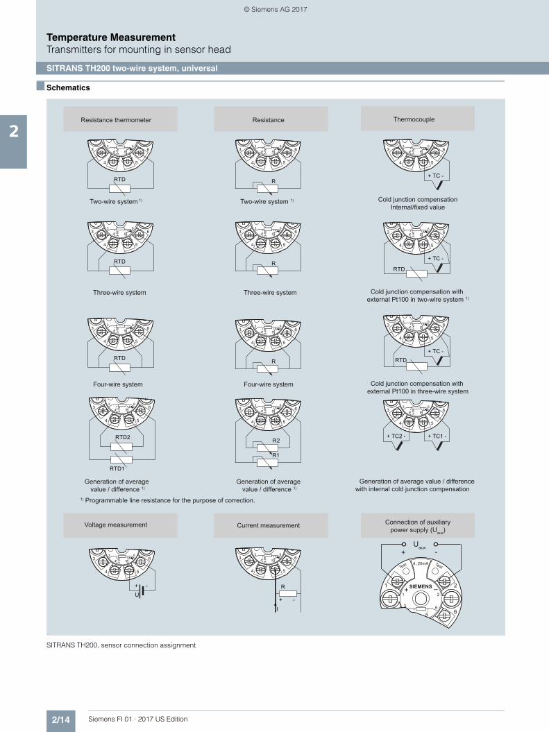
■ Schematics
SITRANS TH200, sensor connection assignment
3 6
4 3-W 5
+ -3
4 5
6
3 6
4 3-W 5
+ -3
4 5
6
3 6
4 3-W 5
+ -3
4 5
6
3 6
4 3-W 5
+ -3
4 5
6
3 6
4 3-W 5
+ -3
4 5
6
3 6
4 3-W 5
+ -3
4 5
6
3 6
4 3-W 5
+ -3
4 5
6
3 6
4 3-W 5
+ -3
4 5
6
3 6
4 3-W 5
+ -3
4 5
6
3 6
4 3-W 5
+ -3
4 5
6
3 6
4 3-W 5
+ -3
4 5
6
3 6
4 3-W 5
+ -3
4 5
6
3 6
4 3-W 5
+ -3
4 5
6
3 6
4 3-W 5
+ -3
4 5
6
1 2
3 6
5
1 SIEMENS
4..20mA
+ – 2
6
Test Test
Resistance thermometer Resistance Thermocouple
Current measurementVoltage measurement Connection of auxiliary power supply (Uaux)
Two-wire system 1)
Three-wire system
Four-wire system
Generation of average value / difference 1)
Two-wire system 1)
Three-wire system
Four-wire system
Generation of average value / difference 1)
Cold junction compensationInternal/fixed value
Cold junction compensation with external Pt100 in two-wire system 1)
Cold junction compensation with external Pt100 in three-wire system
Generation of average value / difference with internal cold junction compensation
1) Programmable line resistance for the purpose of correction.
Uaux+ -
RTD
RTDRTD
R
R
R
R2
UR
I
+ -
+ -
R1
+ TC -
+ TC -
RTD
RTD2
RTD1
RTD+ TC -
+ TC1 - + TC2 -
© Siemens AG 2017

2/15Siemens FI 01 · 2017 US Edition
Temperature MeasurementTransmitters for mounting in sensor head
SITRANS TH300 two-wire system, universal, HART
2
■ Overview
"HART" to beat - the universal SITRANS TH300 transmitter • Two-wire devices for 4 to 20 mA, HART• Mounting in the connection head of the temperature sensor• Universal input for virtually any type of temperature sensor• Configurable over HART
■ Benefits
• Compact design• Flexible mounting and center hole allow you to select your pre-
ferred type of installation• Electrically isolated• Test sockets for multimeters• Diagnostics LED (green/red)• Sensor monitoring
open circuits and short-circuits• Self-monitoring• Configuration status stored in EEPROM• SIL2 (with Order Code C20), SIL2/3 (with C23)• Expanded diagnostic functions, such as slave pointer, operat-
ing hours counter, etc.• Special characteristic• Electromagnetic compatibility to EN 61326 and NE21
■ Application
SITRANS TH300 transmitters can be used in all industrial sec-tors. Due to their compact size they can be installed in the con-nection head type B (DIN 43729) or larger. The following sen-sors/signal sources can be connected over their universal input module:• Resistance thermometers (2, 3 or 4-wire system)• Thermocouples• Resistance-based sensors and DC voltage sources
The output signal is a direct current from 4 to 20 mA in accor-dance with the sensor characteristic, superimposed by the dig-ital HART signal.
Transmitters of the "intrinsically safe" type of protection can be in-stalled within potentially explosive atmospheres. The devices comply with the Directive 94/9/EC (ATEX), as well as FM and CSA regulations.
■ Function
The SITRANS TH300 is configured over HART. This can be done using a handheld communicator or even more conveniently with a HART modem and the SIMATIC PDM parameterization soft-ware. The configuration data are then permanently stored in the non-volatile memory (EEPROM).
Once the sensors and power supply have been correctly con-nected, the transmitter outputs a temperature-linear output sig-nal and the diagnostics LED displays a green light. In the case of a sensor short-circuit, the LED flashes red, an internal device fault is indicated by a steady red light.
The test socket can be used to connect an ammeter at any time for monitoring purposes and plausibility checks. The output cur-rent can be read without any interruption, or even without open-ing the current loop.
SITRANS TH 300 function diagram
InputA/D Analog-digital converterSensors Resistance thermometer, thermocouple, resistance-based sensor, mV sensorμC1 Microcontroller, secondary circuit
OutputμC2 Microcontroller, primary circuitD/A Digital-analog converterUaux Auxiliary power supplyIout Output current
(1) Electrically isolated(2) LED
TC/RTD sensor
(2)
+1
-2(1)
μC1 μC2
Test
4 ... 20 mA Uaux, Iout
SITRANS TH200/TH300
DA
AD
© Siemens AG 2017

2/16 Siemens FI 01 · 2017 US Edition
Temperature MeasurementTransmitters for mounting in sensor head
SITRANS TH300 two-wire system, universal, HART
2
■ Technical specifications
Input
Resistance thermometer
Measured variable Temperature
Sensor type
• to IEC 60751 Pt25 … Pt1000
• To JIS C 1604; a = 0.00392 K-1 Pt25 … Pt1000
• to IEC 60751 Ni25 … Ni1000
• Special type over special characteristic (max. 30 points)
Sensor factor 0.25 ... 10 (adaptation of the basic type, e.g. Pt100 to version Pt25 ... 1000)
Units °C or °F
Connection
• Standard connection 1 resistance thermometer (RTD) in 2-wire, 3-wire or 4-wire system
• Generation of average value 2 identical resistance thermome-ters in 2-wire system for genera-tion of average temperature
• Generation of difference 2 identical resistance thermome-ters (RTD) in 2-wire system (RTD 1 – RTD 2 or RTD 2 – RTD 1)
Interface
• Two-wire system Parameterizable line resistance ≤ 100 Ω (loop resistance)
• Three-wire system No balancing required
• Four-wire system No balancing required
Sensor current ≤ 0.45 mA
Response time ≤ 250 ms for 1 sensor with open-circuit monitoring
Open-circuit monitoring Always active (cannot be dis-abled)
Short-circuit monitoring can be switched on/off (default value: ON)
Measuring range parameterizable (see table "Digi-tal measuring errors")
Min. measured span 10 °C (18 °F)
Characteristic curve Temperature-linear or special characteristic
Resistance-based sensors
Measured variable Actual resistance
Sensor type Resistance-based, potentiome-ters
Units Ω
Connection
• Normal connection 1 resistance-based sensor (R) in 2-wire, 3-wire or 4-wire system
• Generation of average value 2 resistance-based sensors in 2-wire system for generation of average value
• Generation of difference 2 resistance thermometers in 2-wire system (R1 – R2 or R2 – R1)
Interface
• Two-wire system Parameterizable line resistance ≤ 100 Ω (loop resistance)
• Three-wire system No balancing required
• Four-wire system No balancing required
Sensor current ≤ 0.45 mA
Response time ≤ 250 ms for 1 sensor with open-circuit monitoring
Open-circuit monitoring Always active (cannot be dis-abled)
Short-circuit monitoring can be switched on/off (default value: OFF)
Measuring range parameterizable max. 0 ... 2200 Ω (see table "Digital measuring errors")
Min. measured span 5 ... 25 Ω (see table "Digital mea-suring errors")
Characteristic curve Resistance-linear or special char-acteristic
Thermocouples
Measured variable Temperature
Sensor type (thermocouples)
• Type B Pt30Rh-Pt6Rh to DIN IEC 584
• Type C W5 %-Re acc. to ASTM 988
• Type D W3 %-Re acc. to ASTM 988
• Type E NiCr-CuNi to DIN IEC 584
• Type J Fe-CuNi to DIN IEC 584
• Type K NiCr-Ni to DIN IEC 584
• Type L Fe-CuNi to DIN 43710
• Type N NiCrSi-NiSi to DIN IEC 584
• Type R Pt13Rh-Pt to DIN IEC 584
• Type S Pt10Rh-Pt to DIN IEC 584
• Type T Cu-CuNi to DIN IEC 584
• Type U Cu-CuNi to DIN 43710
Units °C or °F
Connection
• Standard connection 1 thermocouple (TC)
• Generation of average value 2 thermocouples (TC)
• Generation of difference 2 thermocouples (TC) (TC1 – TC2 or TC2 – TC1)
Response time ≤ 250 ms for 1 sensor with open-circuit monitoring
Open-circuit monitoring can be switched off
Cold junction compensation
• Internal With integrated Pt100 resistance thermometer
• External With external Pt100 IEC 60571 (2-wire or 3-wire connection)
• External fixed Cold junction temperature can be set as fixed value
Measuring range parameterizable (see table "Digi-tal measuring errors")
Min. measured span Min. 40 ... 100 °C (72 ... 180 °F) (see table "Digital measuring errors")
Characteristic curve Temperature-linear or special characteristic
mV sensor
Measured variable DC voltage
Sensor type DC voltage source (DC voltage source possible over an exter-nally connected resistor)
Units mV
Response time ≤ 250 ms for 1 sensor with open-circuit monitoring
© Siemens AG 2017

2/17Siemens FI 01 · 2017 US Edition
Temperature MeasurementTransmitters for mounting in sensor head
SITRANS TH300 two-wire system, universal, HART
2
Factory setting: • Pt100 (IEC 751) with 3-wire circuit• Measuring range: 0 ... 100 °C (32 ... 212 °F)• Fault current: 22.8 mA• Sensor offset: 0 °C (0 °F)• Damping 0.0 s
Open-circuit monitoring Can be switched off
Measuring range -10 ... +70 mV-100 … +1100 mV
Min. measured span 2 mV or 20 mV
Overload capability of the input -1.5 ... +3.5 V DC
Input resistance ≥ 1 MΩ
Characteristic curve Voltage-linear or special charac-teristic
Output
Output signal 4 ... 20 mA, 2-wire with communi-cation acc. to HART Rev. 5.9
Auxiliary power 11 ... 35 V DC (to 30 V for Ex ia and ib; to 32 V for Ex nA/nL/ic)
Max. load (Uaux –11 V)/0.023 A
Overrange 3.6 ... 23 mA, infinitely adjustable (default range: 3.80 mA ... 20.5 mA)
Error signal (e.g. following sensor fault)(conforming to NE43)
3.6 ... 23 mA, infinitely adjustable (default value: 22.8 mA)
Sample cycle 0.25 s nominal
Damping Software filter 1st order 0 ... 30 s (parameterizable)
Protection Against reversed polarity
Electrically isolated Input against output (1 kVeff)
Measuring accuracy
Digital measuring errors See Table "Digital measuring errors"
Reference conditions
• Auxiliary power 24 V ± 1 %
• Load 500 Ω
• Ambient temperature 23 °C
• Warming-up time > 5 min
Error in the analog output (digi-tal/analog converter)
< 0.025 % of span
Error due to internal cold junction < 0.5 °C (0.9 °F)
Influence of ambient temperature
• Analog measuring error 0.02 % of span/10°C (18 °F)
• Digital measuring errors
- with resistance thermometers 0.06 °C (0.11 °F)/10°C (18 °F)
- with thermocouples 0.6 °C (1.1 °F)/10°C (18 °F)
Auxiliary power effect < 0.001 % of span/V
Effect of load impedance < 0.002 % of span/100 Ω
Long-term drift
• In the first month < 0.02 % of span
• After one year < 0.2 % of span
• After 5 years < 0.3 % of span
Conditions of use
Ambient conditions
Ambient temperature range -40 ... +85 °C (-40 ... +185 °F)
Storage temperature range -40 ... +85 °C (-40 ... +185 °F)
Relative humidity < 98 %, with condensation
Electromagnetic compatibility acc. to EN 61326 and NE21
Construction
Material Molded plastic
Weight 50 g (0.11 lb)
Dimensions See "Dimensional drawings"
Cross-section of cables Max. 2.5 mm² (AWG 13)
Degree of protection to IEC 60529
• Enclosure IP40
• Terminals IP00
Certificates and approvals
Explosion protection ATEX
EC type test certificate PTB 05 ATEX 2040X
• "Intrinsic safety" type of protection II 1 G Ex ia IIC T6/T4II 2 (1) G Ex ia/ib IIC T6/T4II 3(1) G Ex ia/ic IIC T6/T4II 1D Ex iaD 20 T115 °C
• "Operating equipment that is non-ignitable and has limited energy" type of protection
II 3 G Ex nL IIC T6/T4II 3 G Ex nA IIC T6/T4
Explosion protection: FM for USA
• FM approval FM 3024169
• Degree of protection IS / Cl I, II, III / Div 1 / GP ABC-DEFG T6, T5, T4Cl I / ZN 0 / AEx ia IIC T6, T5, T4NI / Cl I / Div 2 / GP ABCDFG T6, T5, T4NI / Cl I / ZN 2 / IIC T6, T5, T4
Explosion protection to FM for Canada (cFMUS)
• FM approval FM 3024169C
• Degree of protection IS / Cl I, II, III / Div 1/ GP ABC-DEFG T6, T5, T4NI / Cl I / DIV 2 / GP ABCD T6, T5, T4NIFW / Cl I, II, III / DIV 2 / GP ABCDFG T6, T5, T4DIP / Cl II, III / Div 2 / GP FG T6, T5, T4Cl I / ZN 0 / Ex ia IIC T6, T5, T4Cl I / ZN 2 / Ex nA nL IIC T6, T5, T4
Other certificates GOST, NEPSI, PESO, IEC, EXPOLABS
© Siemens AG 2017
2/18 Siemens FI 01 · 2017 US Edition
Temperature MeasurementTransmitters for mounting in sensor head
SITRANS TH300 two-wire system, universal, HART
2
Digital measuring errors
Resistance thermometer
Resistance-based sensors
Thermocouples
1) The digital accuracy in the range 0 to 300 °C (32 to 572 °F) is 3 °C (5.4 °F).2) The digital accuracy in the range 1750 to 2300 (3182 to 4172 °F) is 2 °C
(3.6 °F).
mV sensor
The digital accuracy is the accuracy after the analog/digital con-version including linearization and calculation of the measured value.
An additional error is generated in the output current 4 to 20 mA as a result of the digital/analog conversion of 0.025 % of the set span (digital-analog error).
The total error under reference conditions at the analog output is the sum from the digital error and the digital-analog error (poss. with the addition of cold junction errors in the case of thermocou-ple measurements).
Input Measuring range Min. mea-sured span
Digital accuracy
°C/(°F) °C (°F) °C (°F)
to IEC 60751
Pt25 -200 ... +850 (-328 ... +1562)
10 (18) 0.3 (0.54)
Pt50 -200 ... +850 (-328 ... +1562)
10 (18) 0.15 (0.27)
Pt100 ... Pt200 -200 ... +850 (-328 ... +1562)
10 (18) 0.1 (0.18)
Pt500 -200 ... +850 (-328 ... +1562)
10 (18) 0.15 (0.27)
Pt1000 -200 ... +350 (-328 ... +662)
10 (18) 0.15 (0.27)
to JIS C1604-81
Pt25 -200 ... +649 (-328 ... +1200)
10 (18) 0.3 (0.54)
Pt50 -200 ... +649 (-328 ... +1200)
10 (18) 0.15 (0.27)
Pt100 ... Pt200 -200 ... +649 (-328 ... +1200)
10 (18) 0.1 (0.18)
Pt500 -200 ... +649 (-328 ... +1200)
10 (18) 0.15 (0.27)
Pt1000 -200 ... +350 (-328 ... +662)
10 (18) 0.15 (0.27)
Ni 25 to Ni1000 -60 ... +250 (-76 ... +482)
10 (18) 0.1 (0.18)
Input Measuring range Min. mea-sured span
Digital accuracy
Ω Ω Ω
Resistance 0 ... 390 5 0,05
Resistance 0 ... 2200 25 0,25
Input Measuring range Min. mea-sured span
Digital accuracy
°C/(°F) °C (°F) °C (°F)
Type B 0 ... 1820 (32 ... 3308)
100 (180) 21) (3.60)1)
Type C (W5) 0 ... 2300 (32 ... 4172)
100 (180) 2 (3.60)
Type D (W3) 0 ... 2300 (32 ... 4172)
100 (180) 12) (1.80)2)
Type E -200 ... +1000 (-328 ... +1832)
50 (90) 1 (1.80)
Type J -210 ... +1200 (-346 ... +2192)
50 (90) 1 (1.80)
Type K -230 ... +1370 (-382 ... +2498)
50 (90) 1 (1.80)
Type L -200 ... +900 (-328 ... +1652)
50 (90) 1 (1.80)
Type N -200 ... +1300 (-328 ... +2372)
50 (90) 1 (1.80)
Type R -50 ... +1760 (-58 ... +3200)
100 (180) 2 (3.60)
Type S -50 ... +1760 (-58 ... +3200)
100 (180) 2 (3.60)
Type T -200 ... +400 (-328 ... +752)
40 (72) 1 (1.80)
Type U -200 ... +600 (-328 ... +1112)
50 (90) 2 (3.60)
Input Measuring range Min. mea-sured span
Digital accuracy
mV mV μV
mV sensor -10 ... +70 2 40
mV sensor -100 ... +1100 20 400
© Siemens AG 2017
2/19Siemens FI 01 · 2017 US Edition
Temperature MeasurementTransmitters for mounting in sensor head
SITRANS TH300 two-wire system, universal, HART
2
■ Selection and Ordering data Article No.
Supply units see Chapter "Supplementary Components".
Ordering example 1:
7NG3212-0NN00-Z Y01+Y17+U03Y01: -10 ... +100 °CY17: TICA123
Ordering example 2:
7NG3212-0NN00-Z Y01+Y23+U25Y01: -10 ... +100 °CY23: TICA1234HEAT
Factory setting: • Pt100 (IEC 751) with 3-wire circuit• Measuring range: 0 ... 100 °C (32 ... 212 °F)• Fault current: 22.8 mA• Sensor offset: 0 °C (0 °F)• Damping 0.0 s
Temperature transmitter SITRANS TH300
for installation in connection head, type B(DIN 43729), two-wire system 4 ... 20 mA, communication capable to HART, with gal-vanic isolation
• Without explosion protection 7NG3212-0NN00
• With explosion protection
- to ATEX 7NG3212-0AN00
- to FM (CFMUS) 7NG3212-0BN00
Further designs Order code
Add "-Z" to Article No. and specify Order code(s)
with test protocol (5 measuring points) C11
Functional safety SIL2 C20
Functional safety SIL2/3 C23
Customer-specific programmingAdd "-Z" to Article No. and specify Order code(s)
Measuring range to be setSpecify in plain text (max. 5 digits):Y01: ... to ... °C, °F
Y011)
Measuring point no. (TAG), max. 8 characters Y172)
Measuring point descriptor, max. 16 charac-ters
Y232)
Measuring point message, max. 32 characters Y242)
Pt100 (IEC) 2-wire, RL = 0 Ω U023)
Pt100 (IEC) 3-wire U033)
Pt100 (IEC) 4-wire U043)
Thermocouple type B U203)4)
Thermocouple type C (W5) U213)4)
Thermocouple type D (W3) U223)4)
Thermocouple type E U233)4)
Thermocouple type J U243)4)
Thermocouple type K U253)4)
Thermocouple type L U263)4)
Thermocouple type N U273)4)
Thermocouple type R U283)4)
Thermocouple type S U293)4)
Thermocouple type T U303)4)
Thermocouple type U U313)4)
With TC: CJC external (Pt100, 3-wire) U41
With TC: CJC external with fixed value, specify in plain text
Y50
Special differing customer-specific program-ming, specify in plain text
Y095)
Fail-safe value 3.6 mA (instead of 22,8 mA) U362)
Cable extension Transmitter with installed cable extension 200 mm (7.87 inch), for Pt100 in four-wire system
W01
Accessories Article No.
MiniDVD for temperature measuring instru-mentsWith documentation in German, English, French, Spanish, Italian, Portuguese and SIPROM T parameterization software
A5E00364512
HART modem
• With USB connection 7MF4997-1DB
SIMATIC PDM operating software See Section 8
DIN rail adapters for head transmitters 7NG3092-8KA
(Quantity delivered: 5 units)
Connecting cable4-wire, 150 mm, for sensor connections when using head transmitters in the high hinged cover (set with 5 units)
7NG3092-8KC
1) For customer-specific programming for RTD and TC, the start value and the end value of the required measuring span must be specified here.
2) For this selection, Y01 or Y09 must also be selected.3) For this selection, Y01 must also be selected.4) Internal cold junction compensation is selected as the default for TC.5) For customer-specific programming, for example mV and ohm, the start
value and the end value of the required measuring span and the unit must be entered here.
© Siemens AG 2017
2/20 Siemens FI 01 · 2017 US Edition
Temperature MeasurementTransmitters for mounting in sensor head
SITRANS TH300 two-wire system, universal, HART
2
■ Dimensional drawings
SITRANS TH300, dimensions and pin assignment, dimensions in mm (inch)
Mounting on DIN rail
SITRANS TH300, mounting of transmitter on DIN rail
DIN rail adapter, dimensions in mm (inch)
1 2
3
Test Test
6
4 3-W 5
1 SIEMENS+ –
3
4 5
2
6+ -
1(+) and 2(-) Auxiliary power supply Uaux, output current IOut3, 4, 5 and 6 Pt100 sensor (for connections, see Sensor connection assignment)Test (+), Test (-) Measurement of the output current with a multimeter
(1) Test terminal(2) Mounting screw M4x30(3) LED for operation indication(4) Internal diameter of center hole 6.3 (0.25)
26.3
(1.0
4)
(1) (1)
(3)
(2)(2)
Ø 44 (1.73)
33 (1.30)
(4)
M4 x 30
4...20 mA
50.5 (1.99)
59.6
(2.3
5)
33 (1.30)14 (0.55)
© Siemens AG 2017

2/21Siemens FI 01 · 2017 US Edition
Temperature MeasurementTransmitters for mounting in sensor head
SITRANS TH300 two-wire system, universal, HART
2
■ Schematics
SITRANS TH300, sensor connection assignment
3 6
4 3-W 5
+ -3
4 5
6
3 6
4 3-W 5
+ -3
4 5
6
3 6
4 3-W 5
+ -3
4 5
6
3 6
4 3-W 5
+ -3
4 5
6
3 6
4 3-W 5
+ -3
4 5
6
3 6
4 3-W 5
+ -3
4 5
6
3 6
4 3-W 5
+ -3
4 5
6
3 6
4 3-W 5
+ -3
4 5
6
3 6
4 3-W 5
+ -3
4 5
6
3 6
4 3-W 5
+ -3
4 5
6
3 6
4 3-W 5
+ -3
4 5
6
3 6
4 3-W 5
+ -3
4 5
6
3 6
4 3-W 5
+ -3
4 5
6
3 6
4 3-W 5
+ -3
4 5
6
1 2
3 6
5
1 SIEMENS
4..20mA
+ – 2
6
Test Test
Resistance thermometer Resistance Thermocouple
Current measurementVoltage measurement Connection of auxiliary power supply (Uaux)
Two-wire system 1)
Three-wire system
Four-wire system
Generation of average value / difference 1)
Two-wire system 1)
Three-wire system
Four-wire system
Generation of average value / difference 1)
Cold junction compensationInternal/fixed value
Cold junction compensation with external Pt100 in two-wire system 1)
Cold junction compensation with external Pt100 in three-wire system
Generation of average value / difference with internal cold junction compensation
1) Programmable line resistance for the purpose of correction.
Uaux+ -
RTD
RTDRTD
R
R
R
R2
UR
I
+ -
+ -
R1
+ TC -
+ TC -
RTD
RTD2
RTD1
RTD+ TC -
+ TC1 - + TC2 -
© Siemens AG 2017

2/22 Siemens FI 01 · 2017 US Edition
Temperature MeasurementTransmitters for mounting in sensor head
SITRANS TH400 fieldbus transmitter
2
■ Overview
SITRANS TH400 fieldbus transmitters
Versions:• For FOUNDATION fieldbus• For PROFIBUS PA
The SITRANS TH400 temperature transmitter is a small field bus transmitter for mounting in the connection head of form B. Exten-sive functionality enables the temperature transmitter to be pre-cisely adapted to the plant’s requirements. Operation is very simple in spite of the numerous setting options. Thanks to its uni-versal concept it can be used in all industries and is easy to in-tegrate in the context of Totally Integrated Automation applica-tions.
Transmitters of the "intrinsically safe" type of protection can be in-stalled within potentially explosive atmospheres. The devices comply with the Directive 94/9/EC (ATEX), as well as FM and CSA regulations.
Installing SITRANS TH400 in temperature sensors turns them into complete, bus-capable measuring points; compact - and in a single device.
■ Application
• Linearized temperature measurement with resistance ther-mometers or thermal elements
• Differential, mean-value or redundant temperature measure-ment with resistance thermometers or thermal elements
• Linear resistance and bipolar millivolt measurements• Differential, mean-value or redundant resistance and bipolar
millivolt measurements
■ Function
Features• Mounting in connection head, type B, to DIN 43729, or larger• Polarity-neutral bus connection• 24-bit analog-digital converter for high resolution• Electrically isolated• Intrinsically-safe version for use in potentially explosive areas• Special characteristic• Sensor redundance
With PROFIBUS PA communication• Function blocks: 2 x analog
With FOUNDATION fieldbus communication• Function blocks: 2 x analog and 1 x PID• Functionality: Basic or LAS
Mode of operation
The following function diagram explains the mode of operation of the transmitter.
The only difference between the two versions of the SITRANS TH400 (7NG3214-... and 7NG3215-...) is the type of fieldbus protocol used (PROFIBUS PA or FOUNDATION fieldbus).
SITRANS TH400, function diagram
Optional inputs:- Resistance thermometer- Thermocouple- mV sensor- Resistance-based sensors
Input 1
Input 2
TransformerInput 1Input 2DifferentialMean valueRedundancyTerminal temperatureEngineering units Diagnostic functionsTable linearizationPolynomial linearizationProcess calibration
A/D converter
Complex configurationCorrection coefficientFactory settings
- PROFIBUS protocol (7NG3214) or- Foundation Fieldbus protocol (7NG3215)
Bus connection
Ex
pow
er c
ircui
t
Electrically isolated
Internal Pt100
Communication
EEPROM
CPU
6
5
4
32
1
© Siemens AG 2017

2/23Siemens FI 01 · 2017 US Edition
Temperature MeasurementTransmitters for mounting in sensor head
SITRANS TH400 fieldbus transmitter
2
System communication
SITRANS TH400, communication interface
■ Technical specifications
Input
Analog-to-digital conversion
• Measurement rate < 50 ms
• Resolution 24-bit
Resistance thermometer
Pt25 ... Pt1000 to IEC 60751/JIS C 1604
• Measuring range -200 ... +850 °C (-328 ... +1562 °F)
Ni25 ... Ni1000 to DIN 43760
• Measuring range -60 ... +250 °C (-76 ... +482 °F)
Cu10 ... Cu1000, α = 0.00427
• Measuring range -50 ... +200 °C (-58 ... +392 °F)
Line resistance per sensor cable Max. 50 Ω
Sensor current Nominal 0.2 mA
Sensor fault detection
• Sensor break detection Yes
• Sensor short-circuit detection Yes, < 15 Ω
Resistance-based sensors
Measuring range 0 Ω ... 10 kΩ
Line resistance per sensor cable Max. 50 Ω
Sensor current Nominal 0.2 mA
Sensor fault detection
• Sensor break detection Yes
• Sensor short-circuit detection Yes, < 15 Ω
s
s
Output:
Bus terminator
Bus terminator
Segment coupler
Segment coupler
Bus connection
Bus connection
PROFIBUS PA
FOUNDATION Fieldbus
SITRANS TH400 FF
SITRANS TH400 PA
12
12
Thermocouple
to IEC 584 Measuring range
• Type B 400 .. +1820 °C (752 ... 3308 °F)
• Type E -100 ... +1000 °C (-148 ... +1832 °F)
• Type J -100 ... +1000 °C (-148 ... +1832 °F)
• Type K -100 ... +1200 °C (-148 ... +2192 °F)
• Type N -180 ... +1300 °C (-292 ... +2372 °F)
• Type R -50 ... +1760 °C (-58 ... +3200 °F)
• Type S -50 ... +1760 °C (-58 ... +3200 °F)
• Type T -200 ... +400 °C (-328 ... +752 °F)
to DIN 43710
• Type L -200 ... +900 °C (-328 ... +1652 °F)
• Type U -200 ... +600 °C (-328 ... +1112 °F)
to ASTM E988-90
• Type W3 0 ... 2300 °C (32 ... +4172 °F)
• Type W5 0 ... 2300 °C (32 ... +4172 °F)
External cold junction compensa-tion
-40 ... +135 °C (-40 ... +275 °F)
Sensor fault detection
• Sensor break detection Yes
• Sensor short-circuit detection Yes, < 3 mV
• Sensor current in the event of open-circuit monitoring
4 μA
mV sensor - voltage input
Measuring range -800 ... +800 mV
Input resistance 10 MΩ
Output
Filter time (programmable) 0 ... 60 s
Update time < 400 ms
Measuring accuracy
Accuracy is defined as the higher value of general values and basic values.
General values
Type of input Absolute accu-racy
Temperature coefficient
All ≤ ± 0.05 % of the measured value
≤ ± 0.002 % of the measured value/°C
Basic values
Type of input Basic accuracy Temperature coefficient
Pt100 and Pt1000 ≤ ± 0.1 °C ≤ ± 0.002 °C/°C
Ni100 ≤ ± 0.15 °C ≤ ± 0.002 °C/°C
Cu10 ≤ ± 1.3 °C ≤ ± 0.02 °C/°C
Resistance-based sensors ≤ ± 0.05 Ω ≤ ± 0.002 Ω/°C
Voltage source ≤ ± 10 μV ≤ ± 0.2 % μV/°C
Thermocouple, type:E, J, K, L, N, T, U
≤ ± 0.5 °C ≤ ± 0.01 °C/°C
Thermocouple, type:B, R, S, W3, W5
≤ ± 1 °C ≤ ± 0.025 °C/°C
Cold junction compensation ≤ ± 0.5 °C
Reference conditions
Warming-up time 30 s
Signal-to-noise ratio Min. 60 dB
Calibration condition 20 ... 28 °C (68 ... 82 °F)
© Siemens AG 2017
2/24 Siemens FI 01 · 2017 US Edition
Temperature MeasurementTransmitters for mounting in sensor head
SITRANS TH400 fieldbus transmitter
2
Conditions of use
Ambient conditions
Permissible ambient temperature -40 ... +85 °C (-40 ... +185 °F)
Permissible storage temperature -40 ... +85 °C (-40 ... +185 °F)
Relative humidity ≤ 98 %, with condensation
Insulation resistance
• Test voltage 500 V AC for 60 s
Mechanical testing
• Vibrations (DIN class B) to IEC 60068-2-6 andIEC 60068-2-644 g/2 ... 100 Hz
Electromagnetic compatibility
EMC noise voltage influence < ± 0.1 % of span
Extended EMC noise immunity:NAMUR NE 21, criterion A, Burst
< ± 1 % of span
EMC 2004/108/EC Emission and Noise Immunity to
EN 61326
Construction
Material Molded plastic
Weight 55 g (0.12 lb)
Dimensions See Dimensional drawings
Cross-section of cables Max. 2.5 mm2 (AWG 13)
Degree of protection
• Transmitter enclosure IP40
• Terminal IP00
Auxiliary power
Power supply
• Standard, Ex "nA", Ex "nL", NI 9.0 ... 32 V DC
• ATEX, FM, UL and CSA 9.0 ... 30 V DC
• In FISCO/FNICO installations 9.0 ... 17.5 V DC
Power consumption < 11 mA
Max. increase in power consump-tion in the event of a fault
< 7 mA
Certificates and approvals
Explosion protection ATEX
EC type test certificate KEMA 06 ATEX 0264
• "Intrinsic safety" type of protection II 1 G Ex ia IIC T4...T6II 2(1) G Ex ib[ia] IIC T4...T6II 1 D Ex iaD
EC type test certificate KEMA 06 ATEX 0263 X
• Type of protection for "equipment is non-arcing"
II 3 GD Ex nA[nL] IIC T4...T6II 3 GD Ex nL IIC T4...T6II 3 GD Ex nA[ic] IIC T4...T6II 3 GD Ex ic IIC T4...T6
Explosion protection: FM for USA
• FM approval FM 3027985
• Degree of protection • IS Class I, Div 1, Groups A, B, C, D T4/T5/T6, FISCO
• IS Class I, Zone 0, AEx ia, IIC T4/T5/T6, FISCO
• NI Class I, Div 2, Groups A, B, C, D T4/T5/T6, FNICO
Explosion protection CSA for Canada
• CSA approval CSA 1861385
• Degree of protection • IS Class I, Div 1, Groups A, B, C, D T4/T5/T6
• Ex ia IIC T4/T5/T6 and Ex ib [ia] IIC T4/T5/T6
• NI Class I, Div 2, Groups A, B, C, D T4/T5/T6
• Ex nA II T4/T5/T6
Other certificates GOST, PESO
Communication
Parameterization interface
• PROFIBUS PA connection
- Protocol Profile 3.0
- Address (for delivery) 126
• FOUNDATION fieldbus connec-tion
- Protocol FF protocol
- Functionality Basic or LAS
- Version ITK 4.6
- Function blocks 2 x analog and 1 x PID
Factory setting
only for SITRANS TH400 PA
Sensor Pt100 (IEC)
Type of connection 3-wire circuit
Unit °C
Failure mode Last valid value
Filter time 0 s
PA address 126
PROFIBUS Ident No. Manufacturer-specific
only for SITRANS TH400 FF
Sensor Pt100 (IEC)
Type of connection 3-wire circuit
Unit °C
Failure mode Last valid value
Filter time 0 s
Node address 22
© Siemens AG 2017

2/25Siemens FI 01 · 2017 US Edition
Temperature MeasurementTransmitters for mounting in sensor head
SITRANS TH400 fieldbus transmitter
2
■ Selection and Ordering data Article No.
Ordering example 1:
7NG3214-0NN00-Z Y01+Y17+U03Y01: 0...100 °CY17: TICA1234HEAT
Ordering example 2:
7NG3214-0NN00-Z Y01+Y17+Y25+U25Y01: 0...500 °CY17: TICA5678HEATY25: 33
Factory setting: • For SITRANS TH400 PA:
- Pt100 (IEC 751) with 3-wire circuit- Unit: °C- Failure mode: Last valid value- Filter time: 0 s- PA address: 126- PROFIBUS Ident No.: Manufacturer-specific
• For SITRANS TH400 FF: - Pt100 (IEC 751) with 3-wire circuit- Unit: °C- Failure mode: Last valid value- Filter time: 0 s- Node address: 22
Temperature transmitter SITRANS TH400
for installation in connection head, with electrical isolation, order operating instruc-tions separately.
• Bus-compatible to PROFIBUS PA
- No explosion protection or Zone 2/Div 2 to ATEX/FM/CSA/IECEX/NEPSI
7NG3214-0NN00
- With explosion protection "Intrinsically safe to ATEX/FM/CSA/IECEX/NEPSI"
7NG3214-0AN00
• Bus-compatible to FOUNDATION Fieldbus
- No explosion protection or Zone 2/Div 2 to ATEX/FM/CSA/IECEX/NEPSI
7NG3215-0NN00
- With explosion protection "Intrinsically safe to ATEX/FM/CSA/IECEX/NEPSI"
7NG3215-0AN00
Further designs Order code
Please add "-Z" to Article No. and specify Order code(s) and plain text.
With test protocol (5 measuring points) C11
Customer-specific programmingAdd "-Z" to Article No. and specify Order code(s)
Measuring range to be setSpecify in plain text (max. 5 digits):Y01: ... to ... °C, °F
Y011)
Measuring point no. (TAG), max. 32 charac-ters
Y172)
Measuring point descriptor, max. 32 charac-ters
Y232)
Measuring point message, max. 32 charac-ters
Y242)
Bus address, specify in plain text Y252)
Pt100 (IEC) 2-wire, RL = 0 Ω U023)
Pt100 (IEC) 3-wire U033)
Pt100 (IEC) 4-wire U043)
Thermocouple type B U203)4)
Thermocouple type C (W5) U213)4)
Thermocouple type D (W3) U223)4)
Thermocouple type E U233)4)
Thermocouple type J U243)4)
Thermocouple type K U253)4)
Thermocouple type L U263)4)
Thermocouple type N U273)4)
Thermocouple type R U283)4)
Thermocouple type S U293)4)
Thermocouple type T U303)4)
Thermocouple type U U313)4)
With TC: CJC external (Pt100, 3-wire) U41
With TC: CJC external with fixed value, spe-cify in plain text
Y50
Special differing customer-specific program-ming, specify in plain text
Y095)
Accessories Article No.
MiniDVD for temperature measuring instruments
A5E00364512
With documentation in German, English, French, Spanish, Italian, Portuguese and SIPROM T parameterization software
SIMATIC PDM operating software See Chapter 8
DIN rail adapters for head transmitters 7NG3092-8KA
(Quantity delivered: 5 units)
Connecting cable4-wire, 150 mm, for sensor connections when using head transmitters in the high hinged cover (set with 5 units)
7NG3092-8KC
for additional PA components See Catalog IK PI
1) For customer-specific programming for RTD and TC, the start value and the end value of the required measuring span must be specified here.
2) For this selection, Y01 or Y09 must also be selected.3) For this selection, Y01 must also be selected.4) Internal cold junction compensation is selected as the default for TC.5) For customer-specific programming, for example mV and ohm, the start
value and the end value of the required measuring span and the unit must be entered here.
© Siemens AG 2017
2/26 Siemens FI 01 · 2017 US Edition
Temperature MeasurementTransmitters for mounting in sensor head
SITRANS TH400 fieldbus transmitter
2
■ Dimensional drawings
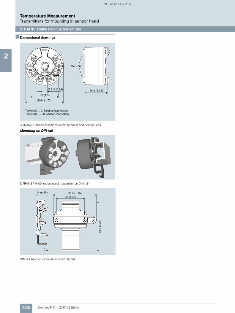
SITRANS TH400 dimensions in mm (inches) and connections
Mounting on DIN rail
SITRANS TH400, mounting of transmitter on DIN rail
DIN rail adaptor, dimensions in mm (inch)
Terminals 1, 2: fieldbus connectionTerminals 3 ... 6: sensor connection
26.3 (1.04)Ø 6.3 (0.25)
33 (1.3)
Ø 44 (1.73)
M4 x 30
s1 2
54
3 6
+ -3-W
50.5 (1.99)
59.6
(2.3
5)
33 (1.30)14 (0.55)
© Siemens AG 2017

2/27Siemens FI 01 · 2017 US Edition
Temperature MeasurementTransmitters for mounting in sensor head
SITRANS TH400 fieldbus transmitter
2
■ Schematics
SITRANS TH400, sensor connection assignment
Resistance thermometer ResistanceThermocouple
Voltage measurement
Two-wire system 1)
Three-wire system
Four-wire system
Two-wire system 1)
Three-wire system
Four-wire system
Internal cold junction compensation
Cold junction compensation with external Pt100 in two-wire system 1)
Cold junction compensation with external Pt100 in three-wire system
1) Programmable line resistance for the purpose of correction.
Mean-value/differential or redundancy generation
1 sensor in two-wire system 1)
1 sensor in three-wire system
Mean-value/differential or redundancy generation2 x two-wire system 1)
Mean value, differential or redundancy generation with internal
cold junction compensation
Mean value, differential or redundancy generation and cold junction compensation
with internal Pt100 in two-wire system 1)
Mean value, differential or redundancy generation1 resistor in two-wire system 1)
1 resistor in three-wire system
Measurement of mean value, differential and redundancy with 2 voltage sources
One voltage source
12
12
+ -
+ -
+ -
12
+ -
12
+ - + -
21+ -
+ -
12
+ -+ -
© Siemens AG 2017
2/28 Siemens FI 01 · 2017 US Edition
Temperature MeasurementTransmitters for rail mounting
SITRANS TR200 two-wire system, universal
2
■ Overview
Ultra flexible - with the universal SITRANS TR200 transmitter • Two-wire devices for 4 to 20 mA• Enclosure for rail mounting• Universal input for virtually any type of temperature sensor• Configurable over PC
■ Benefits
• Compact design• Electrically isolated• Test sockets for multimeters• Diagnostics LED (green/red)• Sensor monitoring
open circuits and short-circuits• Self-monitoring• Configuration status stored in EEPROM• Expanded diagnostic functions, such as slave pointer, operat-
ing hours counter, etc.• Special characteristic• Electromagnetic compatibility to EN 61326 and NE21• SIL2 (with Order Code C20), SIL2/3 (with C23)
■ Application
SITRANS TR200 transmitters can be used in all industrial sec-tors. Their compact design enables simple mounting on stan-dard DIN rails on-site in protective boxes or in control cabinets.The following sensors/signal sources can be connected overtheir universal input module:• Resistance thermometers (2, 3 or 4-wire system)• Thermocouples• Resistance-based sensors and DC voltage sources
The output signal is a direct current from 4 to 20 mA in accor-dance with the sensor characteristic.
Transmitters of the "intrinsically safe" type of protection can be in-stalled within potentially explosive atmospheres. The devices comply with the Directive 94/9/EC (ATEX).
■ Function
The SITRANS TR200 is configured over a PC. A USB or RS 232modem is linked to the output terminals for this purpose. Theconfiguration data can now be edited using the SIPROM T soft-ware tool. The configuration data are then permanently stored in the non-volatile memory (EEPROM).
Once the sensors and power supply have been correctly con-nected, the transmitter outputs a temperature-linear output sig-nal and the diagnostics LED displays a green light. In the caseof a sensor short-circuit, the LED flashes red, an internal devicefault is indicated by a steady red light.
The test socket can be used to connect an ammeter at any timefor monitoring purposes and plausibility checks. The output cur-rent can be read without any interruption, or even without open-ing the current loop.
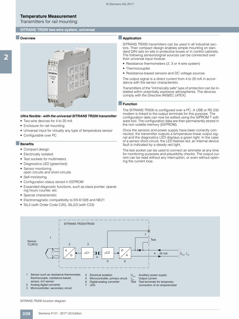
SITRANS TR200 function diagram
1 Sensor such as resistance thermometer, thermocouple, resistance-based, sensor, mV sensor2 Analog-digital converter3 Microcontroller, secondary circuit
4 Electrical isolation5 Microcontroller, primary circuit6 Digital-analog converter7 LED
Uaux Auxiliary power supplyIout Output currentTest Test terminals for temporary
connection of an amperemeter
SensorTC/RTD
A
D
D
AµC1 µC2
Test
4 ... 20 mA Uaux, Iout
SITRANS TR200/TR300
17
6
3
45
2
© Siemens AG 2017

2/29Siemens FI 01 · 2017 US Edition
Temperature MeasurementTransmitters for rail mounting
SITRANS TR200 two-wire system, universal
2
■ Technical specifications
Input
Resistance thermometer
Measured variable Temperature
Sensor type
• to IEC 60751 Pt25 … 1000
• to JIS C 1604; a=0.00392 K-1 Pt25 … 1000
• to IEC 60751 Ni25 … 1000
• Special type over special characteristic(max. 30 points)
Sensor factor 0.25 ... 10 (adaptation of the basic type, e.g. Pt100 to version Pt25 ... 1000)
Units °C or °F
Connection
• Standard connection 1 resistance thermometer (RTD) in 2-wire, 3-wire or 4-wire system
• Generation of average value 2 resistance thermometers in 2-wire system for generation of average temperature
• Generation of difference 2 resistance thermometers (RTD) in 2-wire system (RTD 1 – RTD 2 or RTD 2 – RTD 1)
Interface
• Two-wire system Parameterizable line resistance ≤ 100 Ω (loop resistance)
• Three-wire system No balancing required
• Four-wire system No balancing required
Sensor current ≤ 0.45 mA
Response time T63 ≤ 250 ms for 1 sensor with open-cir-cuit monitoring
Open-circuit monitoring Always active (cannot be disabled)
Short-circuit monitoring can be switched on/off (default value: ON)
Measuring range parameterizable (see table "Digital measuring errors")
Min. measured span 10 °C (18 °F)
Characteristic curve Temperature-linear or special char-acteristic
Resistance-based sensors
Measured variable Actual resistance
Sensor type Resistance-based, potentiometers
Units ΩConnection
• Normal connection 1 resistance-based sensor (R) in 2-wire, 3-wire or 4-wire system
• Generation of average value 2 resistance-based sensors in 2-wire system for generation of average value
• Generation of difference 2 resistance thermometers in 2-wire system (R1 – R2 or R2 – R1)
Interface
• Two-wire system Parameterizable line resistance ≤ 100 Ω (loop resistance)
• Three-wire system No balancing required
• Four-wire system No balancing required
Sensor current ≤ 0.45 mA
Response time T63 ≤ 250 ms for 1 sensor with open-cir-cuit monitoring
Open-circuit monitoring Always active (cannot be disabled)
Short-circuit monitoring can be switched on/off (default value: OFF)
Measuring range parameterizable max. 0 ... 2200 Ω (see table "Digital measuring errors")
Min. measured span 5 ... 25 Ω (see table "Digital measur-ing errors")
Characteristic curve Resistance-linear or special charac-teristic
Thermocouples
Measured variable Temperature
Sensor type (thermocouples)
• Type B Pt30Rh-Pt6Rh to DIN IEC 584• Type C W5 %-Re acc. to ASTM 988• Type D W3 %-Re acc. to ASTM 988
• Type E NiCr-CuNi to DIN IEC 584• Type J Fe-CuNi to DIN IEC 584• Type K NiCr-Ni to DIN IEC 584
• Type L Fe-CuNi to DIN 43710• Type N NiCrSi-NiSi to DIN IEC 584• Type R Pt13Rh-Pt to DIN IEC 584
• Type S Pt10Rh-Pt to DIN IEC 584• Type T Cu-CuNi to DIN IEC 584• Type U Cu-CuNi to DIN 43710
Units °C or °F
Connection
• Standard connection 1 thermocouple (TC)
• Generation of average value 2 thermocouples (TC)
• Generation of difference 2 thermocouples (TC) (TC1 – TC2 or TC2 – TC1)
Response time T63 ≤ 250 ms for 1 sensor with open-cir-cuit monitoring
Open-circuit monitoring Can be switched off
Cold junction compensation
• Internal With integrated Pt100 resistance thermometer
• External With external Pt100 IEC 60571 (2-wire or 3-wire connection)
• External fixed Cold junction temperature can be set as fixed value
Measuring range parameterizable (see table "Digital measuring errors")
Min. measured span Min. 40 ... 100 °C (72 ... 180 °F) (see table "Digital measuring errors")
Characteristic curve Temperature-linear or special char-acteristic
mV sensor
Measured variable DC voltage
Sensor type DC voltage source (DC voltage source possible over an externally connected resistor)
Units mV
Response time T63 ≤ 250 ms for 1 sensor with open-cir-cuit monitoring
Open-circuit monitoring Can be switched off
Measuring range parameterizable max. -100 … 1100 mV
Min. measured span 2 mV or 20 mV
Overload capability of the input -1.5 ... +3.5 V DC
Input resistance ≥ 1 MΩ
Characteristic curve Voltage-linear or special character-istic
© Siemens AG 2017

2/30 Siemens FI 01 · 2017 US Edition
Temperature MeasurementTransmitters for rail mounting
SITRANS TR200 two-wire system, universal
2
Factory setting: • Pt100 (IEC 751) with 3-wire circuit• Measuring range: 0 ... 100 °C (32 ... 212 °F)• Error signal in the event of sensor breakage: 22.8 mA• Sensor offset: 0 °C (0 °F)• Damping 0.0 s
Digital measuring errors
Resistance thermometer
Output
Output signal 4 ... 20 mA, 2-wire
Auxiliary power 11 ... 35 V DC (to 30 V for Ex i/ic; to 32 V for Ex nA)
Max. load (Uaux – 11 V)/0.023 A
Overrange 3.6 ... 23 mA, infinitely adjustable (default range: 3.84 mA ... 20.5 mA)
Error signal (e.g. following sensor fault) (conforming to NE43)
3.6 ... 23 mA, infinitely adjustable (default value: 22.8 mA)
Sample cycle 0.25 s nominal
Damping Software filter 1st order 0 ... 30 s (parameterizable)
Protection Against reversed polarity
Electrically isolated Input against output 2.12 kV DC (1.5 kVeff AC)
Measuring accuracy
Digital measuring errors See Table "Digital measuring errors"
Reference conditions
• Auxiliary power 24 V ± 1 %
• Load 500 Ω
• Ambient temperature 23 °C
• Warming-up time > 5 min
Error in the analog output (digi-tal/analog converter)
< 0.025 % of span
Error due to internal cold junction < 0.5 °C (0.9 °F)
Influence of ambient temperature
• Analog measuring error 0.02 % of span/10 °C (18 °F)
• Digital measuring errors
- With resistance thermometer 0.06 °C (0.11 °F)/10 °C (18 °F)
- with thermocouples 0.6 °C (1.1 °F)/10 °C (18 °F)
Auxiliary power effect < 0.001 % of span/V
Effect of load impedance < 0.002 % of span/100 Ω
Long-term drift
• In the first month < 0.02 % of span in the first month
• After one year < 0.2 % of span after one year
• After 5 years < 0.3 % of span after 5 years
Conditions of use
Ambient conditions
Ambient temperature range -40 ... +85 °C (-40 ... +185 °F)
Storage temperature range -40 ... +85 °C (-40 ... +185 °F)
Relative humidity < 98 %, with condensation
Electromagnetic compatibility acc. to EN 61326 and NE21
Construction
Material Plastic, electronic module potted
Weight 122 g
Dimensions See "Dimensional drawings"
Cross-section of cables Max. 2.5 mm² (AWG 13)
Degree of protection to IEC 60529
• Enclosure IP20
Certificates and approvals
Explosion protection ATEX
EC type test certificate PTB 07 ATEX 2032X
• "Intrinsic safety" type of protec-tion
II 2(1) G Ex ia/ib IIC T6/T4II 3(1) G Ex ia/ic IIC T6/T4II 3 G Ex ic IIC T6/T4II 2(1) D Ex iaD/ibD 20/21 T115 °C
• Type of protection, "equipment is non-arcing"
II 3 G Ex nA IIC T6/T4
Other certificates NEPSI
Software requirements for SIPROM T
PC operating system Windows ME, 2000, XP, Win 7 and Win 8; can also be used in connec-tion with RS 232 modem under Windows 95, 98 and 98SE
Input Measuring range Min. mea-sured span
Digital accuracy
°C/(°F) °C (°F) °C (°F)
to IEC 60751
Pt25 -200 ... +850 (-328 ... +1562)
10 (18) 0.3 (0.54)
Pt50 -200 ... +850 (-328 ... +1562)
10 (18) 0.15 (0.27)
Pt100 ... Pt200 -200 ... +850 (-328 ... +1562)
10 (18) 0.1 (0.18)
Pt500 -200 ... +850 (-328 ... +1562)
10 (18) 0.15 (0.27)
Pt1000 -200 ... +350 (-328 ... +662)
10 (18) 0.15 (0.27)
to JIS C1604-81
Pt25 -200 ... +649 (-328 ... +1200)
10 (18) 0.3 (0.54)
Pt50 -200 ... +649 (-328 ... +1200)
10 (18) 0.15 (0.27)
Pt100 ... Pt200 -200 ... +649 (-328 ... +1200)
10 (18) 0.1 (0.18)
Pt500 -200 ... +649 (-328 ... +1200)
10 (18) 0.15 (0.27)
Pt1000 -200 ... +350 (-328 ... +662)
10 (18) 0.15 (0.27)
Ni 25 to Ni1000 -60 ... +250 (-76 ... +482)
10 (18) 0.1 (0.18)
© Siemens AG 2017

2/31Siemens FI 01 · 2017 US Edition
Temperature MeasurementTransmitters for rail mounting
SITRANS TR200 two-wire system, universal
2
Resistance-based sensors
Thermocouples
1) The digital accuracy in the range 0 to 300 °C (32 to 572 °F) is 3 °C (5.4 °F).2) The digital accuracy in the range 1750 to 2300 °C (3182 to 4172 °F) is 2 °C
(3.6 °F).
mV sensor
The digital accuracy is the accuracy after the analog/digital con-version including linearization and calculation of the measured value.
An additional error is generated in the output current 4 to 20 mA as a result of the digital/analog conversion of 0.025 % of the set span (digital-analog error).
The total error under reference conditions at the analog output is the sum from the digital error and the digital-analog error (poss. with the addition of cold junction errors in the case of thermocou-ple measurements).
Input Measuring range Min. mea-sured span
Digital accuracy
Ω Ω Ω
Resistance 0 ... 390 5 0.05
Resistance 0 ... 2200 25 0.25
Input Measuring range Min. mea-sured span
Digital accuracy
°C/(°F) °C (°F) °C (°F)
Type B 0 ... 1820(32 ... 3308)
100 (180) 21) (3.6)1)
Type C (W5) 0 ... 2300(32 ... 4172)
100 (180) 2 (3.6)
Type D (W3) 0 ... 2300(32 ... 4172)
100 (180) 12) (1.8)2)
Type E -200 ... +1000(-328 ... +1832)
50 (90) 1 (1.8)
Type J -210 ... +1200(-346 ... +2192)
50 (90) 1 (1.8)
Type K -230 ... +1370(-382 ... +2498)
50 (90) 1 (1.8)
Type L -200 ... +900(-328 ... +1652)
50 (90) 1 (1.8)
Type N -200 ... +1300(-328 ... +2372)
50 (90) 1 (1.8)
Type R -50 ... +1760(-58 ... +3200)
100 (180) 2 (3.6)
Type S -50 ... +1760(-58 ... +3200)
100 (180) 2 (3.6)
Type T -200 ... +400(-328 ... +752)
40 (72) 1 (1.8)
Type U -200 ... +600(-328 ... +1112)
50 (90) 2 (3.6)
Input Measuring range
Min. measured span
Digital accuracy
mV mV μV
mV sensor -10 ... +70 2 40
mV sensor -100 ... +1100 20 400
© Siemens AG 2017
2/32 Siemens FI 01 · 2017 US Edition
Temperature MeasurementTransmitters for rail mounting
SITRANS TR200 two-wire system, universal
2
■ Selection and Ordering data Article No.
Supply units see Chapter "Supplementary Components".
Ordering example 1:
7NG3032-0JN00-Z Y01+Y17+Y29+U03Y01: -10 ... +100 °CY17: TICA123Y29: TICA123
Ordering example 2:
7NG3032-0JN00-Z Y01+Y17+Y23+Y29+U25Y01: -10 ... +100 °CY17: TICA123Y23: TICA123HEATY29: TICA123HEAT
Factory setting: • Pt100 (IEC 751) with 3-wire circuit• Measuring range: 0 … 100 °C (32 … 212 °F)• Fault current: 22.8 mA• Sensor offset: 0 °C (0 °F)• Damping 0.0 s
Temperature transmitter SITRANS TR200
For mounting on a standard DIN rail, two-wire system, 4 to 20 mA, programmable, with electri-cal isolation, with documentation on MiniDVD
• Without explosion protection 7NG3032-0JN00
• With explosion protection to ATEX 7NG3032-1JN00
Further designs Order code
Please add "-Z" to Article No. with and specify Order codes(s).
With test protocol (5 measuring points) C11
Functional safety SIL2 C20
Functional safety SIL2/3 C23
Customer-specific programmingAdd "-Z" to Article No. and specify Order code(s)
Measuring range to be setSpecify in plain text (max. 5 digits):Y01: ... to ... °C, °F
Y011)
Measuring point no. (TAG), max. 8 characters Y172)
Measuring point descriptor, max. 16 charac-ters
Y232)
Measuring point message, max. 32 characters Y242)
Text on front label, max. 16 characters Y292)3)
Pt100 (IEC) 2-wire, RL = 0 Ω U024)
Pt100 (IEC) 3-wire U034)
Pt100 (IEC) 4-wire U044)
Thermocouple type B U204)5)
Thermocouple type C (W5) U214)5)
Thermocouple type D (W3) U224)5)
Thermocouple type E U234)5)
Thermocouple type J U244)5)
Thermocouple type K U254)5)
Thermocouple type L U264)5)
Thermocouple type N U274)5)
Thermocouple type R U284)5)
Thermocouple type S U294)5)
Thermocouple type T U304)5)
Thermocouple type U U314)5)
With TC: CJC external (Pt100, 3-wire) U41
With TC: CJC external with fixed value, specify in plain text
Y50
Special differing customer-specific program-ming, specify in plain text
Y096)
Fail-safe value 3.6 mA (instead of 22.8 mA) U362)
Accessories Article No.
Modem for SITRANS TH100, TH200, TR200 and TF with TH200 incl. SIPROM T parame-terization software
7NG3092-8KU
With USB connection
MiniDVD for temperature measuring instru-ments for
A5E00364512
With documentation in German, English, French, Spanish, Italian, Portuguese and SIPROM T parameterization software
1) For customer-specific programming for RTD and TC, the start value and the end value of the required measuring span must be specified here.
2) For this selection, Y01 or Y09 must also be selected.3) Text on front plate is not saved in the device.4) For this selection, Y01 must also be selected.5) Internal cold junction compensation is selected as the default for TC.6) For customer-specific programming, for example mV and ohm, the start
value and the end value of the required measuring span and the unit must be entered here.
© Siemens AG 2017

2/33Siemens FI 01 · 2017 US Edition
Temperature MeasurementTransmitters for rail mounting
SITRANS TR200 two-wire system, universal
2
■ Dimensional drawings
SITRANS TR200, dimensions in mm (inch)
■ Schematics
SITRANS TR200, pin assignments
Connection Plan
Made in Croatia
RTD or R2W sensor
RTD or R3W sensor
RTD or R4W sensor
5678 5678 5678
4..20mA loop& test
2x RTD or R2W sensor
2x TC sensorwith int./fixed
CJC
1
A
23
+UB - TEST+ -
4
56
S2
S1
785
S1S2
6
+ +
78
TC sens. withint./fixed CJC
U sensor
TC sensorwith external2W RTD CJC
TC sensorwith external3W RTD CJC
+
5678
+
5678
+
56
+
78
22.5
SIE
ME
NS
SIT
RA
NS
TR
200
56
78
12
TES
T4.
.20m
A
34
(0.8
9)
(3.9)99
114
(4.4
9)
1 (+) and 2 (-) Test terminals (test) for measurement of the output current with a multimeter3 (+) and 4 (-) Power supply Uaux, output current Iout 5, 6, 7 and 8 Sensor assignment, see schematics
Asssignments
SIEMENS
SITRANS TR200
5 6 7 8
1 2TEST 4..20mA
3 4
© Siemens AG 2017

2/34 Siemens FI 01 · 2017 US Edition
Temperature MeasurementTransmitters for rail mounting
SITRANS TR200 two-wire system, universal
2
SITRANS TR200, sensor connection assignment
++-- ++--
Current measurement Voltage measurement
Three-wire system
Four-wire system
Generation of averagevalue/difference 1)
Three-wire system
Four-wire system
Generation of averagevalue/difference 1)
Generation of average value / differencewith internal cold junction compensation
1) Programmable line resistance for the purpose of correction.
Test terminals
Resistance thermometer Resistance Thermocouple
Power supply/4 ... 20 mA (Uaux)
Two-wire system 1) Two-wire system 1) Cold junction compensationinternal/fixed value
Cold junction compensation withexternal Pt100 in two-wire system 1)
Cold junction compensation withexternal Pt100 in three-wire system
++--5 6 7 85 6 7 8
5 6 7 85 6 7 8
5 6 7 85 6 7 85 6 7 85 6 7 8 5 6 7 85 6 7 8
5 6 7 85 6 7 8 5 6 7 85 6 7 8
5 6 7 85 6 7 85 6 7 85 6 7 85 6 7 85 6 7 8
5 6 7 85 6 7 8 5 6 7 85 6 7 85 6 7 85 6 7 8
1 2 3 41 2 3 41 2 3 41 2 3 4
5 6 7 85 6 7 8
++--
++ --AA
RTD
R
RTD R
RTD
RTD1
RTD2
R
TC
TC
RTD
TC
RTD
+-
+-
+-
TC1 TC2
Uaux+ -
R
IU
R2R2
R1R1
© Siemens AG 2017

2/35Siemens FI 01 · 2017 US Edition
Temperature MeasurementTransmitters for rail mounting
SITRANS TR300 two-wire system, universal, HART
2
■ Overview
"HART" to beat - the universal SITRANS TR300 transmitter • Two-wire devices for 4 to 20 mA, HART• Device for rail mounting• Universal input for virtually any type of temperature sensor • Configurable over HART
■ Benefits
• Compact design• Electrically isolated• Test sockets for multimeters• Diagnostics LED (green/red)• Sensor monitoring
open circuits and short-circuits• Self-monitoring• Configuration status stored in EEPROM• Expanded diagnostic functions, such as slave pointer, operat-
ing hours counter, etc.• Special characteristic• Electromagnetic compatibility to EN 61326 and NE21• SIL2 (with Order Code C20), SIL2/3 (with C23)
■ Application
SITRANS TR300 transmitters can be used in all industrial sec-tors. Their compact design enables simple mounting on stan-dard DIN rails on-site in protective boxes or in control cabinets. The following sensors/signal sources can be connected over their universal input module:• Resistance thermometers (2, 3 or 4-wire system)• Thermocouples• Resistance-based sensors and DC voltage sources
The output signal is a direct current from 4 to 20 mA in accor-dance with the sensor characteristic, superimposed by the dig-ital HART signal.
Transmitters of the "intrinsically safe" type of protection can be in-stalled within potentially explosive atmospheres. The devices comply with the Directive 94/9/EC (ATEX).
■ Function
The SITRANS TR300 is configured over HART. This can be done using a handheld communicator or even more conveniently with a HART modem and the SIMATIC PDM parameterization soft-ware. The configuration data are then permanently stored in the non-volatile memory (EEPROM).
Once the sensors and power supply have been correctly con-nected, the transmitter outputs a temperature-linear output sig-nal and the diagnostics LED displays a green light. In the case of a sensor short-circuit, the LED flashes red, an internal device fault is indicated by a steady red light.
The test socket can be used to connect an ammeter at any time for monitoring purposes and plausibility checks. The output cur-rent can be read without any interruption, or even without open-ing the current loop.
SITRANS TR300 function diagram
1 Sensor such as resistance thermometer, thermocouple, resistance-based, sensor, mV sensor2 Analog-digital converter3 Microcontroller, secondary circuit
4 Electrical isolation5 Microcontroller, primary circuit6 Digital-analog converter7 LED
Uaux Auxiliary power supplyIout Output currentTest Test terminals for temporary connection of an amperemeter
SensorTC/RTD
A
D
D
AµC1 µC2
Test
4 ... 20 mA Uaux, Iout
SITRANS TR200/TR300
17
6
3
45
2
© Siemens AG 2017

2/36 Siemens FI 01 · 2017 US Edition
Temperature MeasurementTransmitters for rail mounting
SITRANS TR300 two-wire system, universal, HART
2
■ Technical specifications
Input
Resistance thermometer
Measured variable Temperature
Sensor type
• to IEC 60751 Pt25 … Pt1000
• to JIS C 1604; a=0.00392 K-1 Pt25 … Pt1000
• to IEC 60751 Ni25 … Pt1000
• Special type over special characteristic (max. 30 points)
Sensor factor 0.25 ... 10 (adaptation of the basic type, e.g. Pt100 to version Pt25 ... 1000)
Units °C or °F
Connection
• Standard connection 1 resistance thermometer (RTD) in 2-wire, 3-wire or 4-wire system
• Generation of average value 2 identical resistance thermome-ters in 2-wire system for genera-tion of average temperature
• Generation of difference 2 identical resistance thermome-ters (RTD) in 2-wire system (RTD 1 – RTD 2 or RTD 2 – RTD 1)
Interface
• Two-wire system Parameterizable line resistance ≤ 100 Ω (loop resistance)
• Three-wire system No balancing required
• Four-wire system No balancing required
Sensor current ≤ 0.45 mA
Response time T63 ≤ 250 ms for 1 sensor with open-circuit monitoring
Open-circuit monitoring Always active (cannot be isabled)
Short-circuit monitoring can be switched on/off (default value: ON)
Measuring range parameterizable (see table "Digital measuring errors")
Min. measured span 10 °C (18 °F)
Characteristic curve Temperature-linear or special characteristic
Resistance-based sensors
Measured variable Actual resistance
Sensor type Resistance-based, potentiome-ters
Units Ω
Connection
• Normal connection 1 resistance-based sensor (R) in 2-wire, 3-wire or 4-wire system
• Generation of average value 2 resistance-based sensors in 2-wire system for generation of average value
• Generation of difference 2 resistance thermometers in 2-wire system (R1 – R2 or R2 – R1)
Interface
• Two-wire system Parameterizable line resistance ≤ 100 Ω (loop resistance)
• Three-wire system No balancing required
• Four-wire system No balancing required
Sensor current ≤ 0.45 mA
Response time T63 ≤ 250 ms for 1 sensor with open-circuit monitoring
Open-circuit monitoring Always active (cannot be dis-abled)
Short-circuit monitoring can be switched on/off (default value: OFF)
Measuring range parameterizable max. 0 ... 2200 Ω (see table "Digital measuring errors")
Min. measured span 5 ... 25 Ω (see table "Digital mea-suring errors")
Characteristic curve Resistance-linear or special char-acteristic
Thermocouples
Measured variable Temperature
Sensor type (thermocouples)
• Type B Pt30Rh-Pt6Rh to DIN IEC 584• Type C W5 %-Re acc. to ASTM 988• Type D W3 %-Re acc. to ASTM 988
• Type E NiCr-CuNi to DIN IEC 584• Type J Fe-CuNi to DIN IEC 584• Type K NiCr-Ni to DIN IEC 584
• Type L Fe-CuNi to DIN 43710• Type N NiCrSi-NiSi to DIN IEC 584• Type R Pt13Rh-Pt to DIN IEC 584
• Type S Pt10Rh-Pt to DIN IEC 584• Type T Cu-CuNi to DIN IEC 584• Type U Cu-CuNi to DIN 43710
Units °C or °F
Connection
• Standard connection 1 thermocouple (TC)
• Generation of average value 2 thermocouples (TC)
• Generation of difference 2 thermocouples (TC) (TC1 – TC2 or TC2 – TC1)
Response time T63 ≤ 250 ms for 1 sensor with open-circuit monitoring
Open-circuit monitoring Can be switched off
Cold junction compensation
• Internal With integrated Pt100 resistance thermometer
• External With external Pt100 IEC 60571 (2-wire or 3-wire connection)
• External fixed Cold junction temperature can be set as fixed value
Measuring range parameterizable (see table "Digital measuring errors")
Min. measured span Min. 40 ... 100 °C (72 ... 180 °F) (see table "Digital measuring errors")
Characteristic curve Temperature-linear or special characteristic
mV sensor
Measured variable DC voltage
Sensor type DC voltage source (DC voltage source possible over an exter-nally connected resistor)
Units mV
Response time T63 ≤ 250 ms for 1 sensor with open-circuit monitoring
Open-circuit monitoring Can be switched off
© Siemens AG 2017

2/37Siemens FI 01 · 2017 US Edition
Temperature MeasurementTransmitters for rail mounting
SITRANS TR300 two-wire system, universal, HART
2
Factory setting: • Pt100 (IEC 751) with 3-wire circuit• Measuring range: 0 ... 100 °C (32 ... 212 °F)• Error signal in the event of sensor breakage: 22.8 mA• Sensor offset: 0 °C (0 °F)• Damping 0.0 s
Measuring range parameterizable max. -100 … 1100 mV
Min. measured span 2 mV or 20 mV
Overload capability of the input -1.5 ... +3.5 V DC
Input resistance ≥ 1 MΩ
Characteristic curve Voltage-linear or special charac-teristic
Output
Output signal 4 ... 20 mA, 2-wire with communi-cation acc. to HART Rev. 5.9
Auxiliary power 11 ... 35 V DC (to 30 V for Ex i/ic; to 32 V for Ex nA)
Max. load (Uaux –11 V)/0.023 A
Overrange 3.6 ... 23 mA, infinitely adjustable (default range: 3.84 ... 20.5 mA)
Error signal (e.g. following sensor fault) (conforming to NE43)
3.6 ... 23 mA, infinitely adjustable (default value: 22.8 mA)
Sample cycle 0.25 s nominal
Damping Software filter 1st order 0 ... 30 s (parameterizable)
Protection Against reversed polarity
Electrical isolation Input against output (1 kVeff)
Measuring accuracy
Digital measuring errors see table "Digital measuring errors"
Reference conditions
• Auxiliary power 24 V ± 1 %
• Load 500 Ω
• Ambient temperature 23 °C
• Warming-up time > 5 min
Error in the analog output (digi-tal/analog converter)
< 0.025 % of span
Error due to internal cold junction < 0.5 °C (0.9 °F)
Ambient temperature effect• Analog measuring errors of span < 0.2 % of max. span/10 °C (18 °F)• Digital measuring errors
- at resistance thermometers- at thermocouples
0.06 °C (0.11 °F)/10 °C (18 °F)0.6 °C (1.1 °F)/10 °C (18 °F)
Auxiliary power effect < 0.001 % of span/V
Effect of load impedance < 0.002 % of span/100 Ω
Long-term drift
• In the first month < 0.02 % of span in the first month
• After one year < 0.2 % of span after one year
• After 5 years < 0.3 % of span after 5 years
Conditions of use
Ambient conditions
Ambient temperature range -40 ... +85 °C (-40 ... +185 °F)
Storage temperature range -40 ... +85 °C (-40 ... +185 °F)
Relative humidity < 98 %, with condensation
Electromagnetic compatibility acc. to EN 61326 and NE21
Design
Material Plastic, electronic module potted
Weight 122 g
Dimensions See "Dimensional drawings"
Cross-section of cables Max. 2.5 mm² (AWG 13)
Degree of protection to IEC 60529
• Enclosure IP20
Certificates and approvals
Explosion protection ATEX
EC type test certificate PTB 07 ATEX 2032X
• "Intrinsic safety" type of protection II 2(1) G Ex ia/ib IIC T6/T4II 3(1) G Ex ia/ic IIC T6/T4II 3 G Ex ic IIC T6/T4II 2(1) D Ex iaD/ibD 20/21 T115 °C
• Type of protection, "equipment is non-arcing"
II 3 G Ex nA IIC T6/T4
Other certificates NEPSI
© Siemens AG 2017

2/38 Siemens FI 01 · 2017 US Edition
Temperature MeasurementTransmitters for rail mounting
SITRANS TR300 two-wire system, universal, HART
2
Digital measuring errors
Resistance thermometer
Resistance-based sensors
Thermocouples
1) The digital accuracy in the range 0 to 300 °C (32 to 572 °F) is 3 °C (5.4 °F).2) The digital accuracy in the range 1750 to 2300 °C (3182 to 4172 °F) is 2 °C
(3.6 °F).
mV sensor
The digital accuracy is the accuracy after the analog/digital con-version including linearization and calculation of the measured value.
An additional error is generated in the output current 4 to 20 mA as a result of the digital/analog conversion of 0,025 % of the set span (digital-analog error).
The total error under reference conditions at the analog output is the sum from the digital error and the digital-analog error (poss. with the addition of cold junction errors in the case of thermocou-ple measurements).
Input Measuring range Min. mea-sured span
Digital accuracy
°C / (°F) °C (°F) °C (°F)
to IEC 60751
Pt25 -200 ... +850 (-328 ... +1562)
10 (18) 0.3 (0.54)
Pt50 -200 ... +850 (-328 ... +1562)
10 (18) 0.15 (0.27)
Pt100 ... Pt200 -200 ... +850 (-328 ... +1562)
10 (18) 0.1 (0.18)
Pt500 -200 ... +850 (-328 ... +1562)
10 (18) 0.15 (0.27)
Pt1000 -200 ... +350 (-328 ... +662)
10 (18) 0.15 (0.27)
to JIS C1604-81
Pt25 -200 ... +649 (-328 ... +1200)
10 (18) 0.3 (0.54)
Pt50 -200 ... +649 (-328 ... +1200)
10 (18) 0.15 (0.27)
Pt100 ... Pt200 -200 ... +649 (-328 ... +1200)
10 (18) 0.1 (0.18)
Pt500 -200 ... +649 (-328 ... +1200)
10 (18) 0.15 (0.27)
Pt1000 -200 ... +350 (-328 ... +662)
10 (18) 0.15 (0.27)
Ni 25 to Ni1000 -60 ... +250 (-76 ... +482)
10 (18) 0.1 (0.18)
Input Measuring range Min. mea-sured span
Digital accuracy
Ω Ω Ω
Resistance 0 ... 390 5 0.05
Resistance 0 ... 2200 25 0.25
Input Measuring range Min. mea-sured span
Digital accuracy
°C / (°F) °C (°F) °C (°F)
Type B 0 ... 1820(32 ... 3308)
100 (180) 21) (3.6)1)
Type C (W5) 0 ... 2300(32 ... 4172)
100 (180) 2 (3.6)
Type D (W3) 0 ... 2300(32 ... 4172)
100 (180) 12) (1.8)2)
Type E -200 ... +1000(-328 ... +1832)
50 (90) 1 (1.8)
Type J -210 ... +1200(-346 ... +2192)
50 (90) 1 (1.8)
Type K -230 ... +1370(-382 ... +2498)
50 (90) 1 (1.8)
Type L -200 ... +900(-328 ... +1652)
50 (90) 1 (1.8)
Type N -200 ... +1300(-328 ... +2372)
50 (90) 1 (1.8)
Type R -50 ... +1760(-58 ... +3200)
100 (180) 2 (3.6)
Type S -50 ... +1760(-58 ... +3200)
100 (180) 2 (3.6)
Type T -200 ... +400(-328 ... +752)
40 (72) 1 (1.8)
Type U -200 ... +600(-328 ... +1112)
50 (90) 2 (3.6)
Input Measuring range Min. mea-sured span
Digital accuracy
mV mV μV
mV sensor -10 ... +70 2 40
mV sensor -100 ... +1100 20 400
© Siemens AG 2017
2/39Siemens FI 01 · 2017 US Edition
Temperature MeasurementTransmitters for rail mounting
SITRANS TR300 two-wire system, universal, HART
2
■ Selection and Ordering data Article No.
Supply units see Chapter "Supplementary Components".
Ordering example 1:
7NG3033-0JN00-Z Y01+Y17+Y29+U03Y01: -10 ... +100 °CY17: TICA123Y29: TICA123
Ordering example 2:
7NG3033-0JN00-Z Y01+Y17+Y23+Y29+U25Y01: -10 ... +100 °CY17: TICA123Y23: TICA123HEATY29: TICA123HEAT
Factory setting: • Pt100 (IEC 751) with 3-wire circuit• Measuring range: 0 ... 100 °C (32 ... 212 °F)• Error signal in the event of sensor breakage: 22.8 mA• Sensor offset: 0 °C (0 °F)• Damping 0.0 s
Temperature transmitter SITRANS TR300
For mounting on a standard DIN rail, two-wire system, 4 … 20 mA, HART, with electrical iso-lation, with documentation on MIniDVD
• Without explosion protection 7NG3033-0JN00
• With explosion protection to ATEX 7NG3033-1JN00
Further designs Order code
Please add "-Z" to Article No. with and specify Order codes(s).
With test protocol (5 measuring points) C11
Functional safety SIL2 C20
Functional safety SIL2/3 C23
Customer-specific programmingAdd "-Z" to Article No. and specify Order code(s)
Measuring range to be setSpecify in plain text (max. 5 digits):Y01: ... to ... °C, °F
Y011)
Measuring point no. (TAG), max. 8 characters Y172)
Measuring point descriptor, max. 16 charac-ters
Y232)
Measuring point message, max. 32 characters Y242)
Text on front label, max. 16 characters Y292)3)
Pt100 (IEC) 2-wire, RL = 0 Ω U024)
Pt100 (IEC) 3-wire U034)
Pt100 (IEC) 4-wire U044)
Thermocouple type B U204)5)
Thermocouple type C (W5) U214)5)
Thermocouple type D (W3) U224)5)
Thermocouple type E U234)5)
Thermocouple type J U244)5)
Thermocouple type K U254)5)
Thermocouple type L U264)5)
Thermocouple type N U274)5)
Thermocouple type R U284)5)
Thermocouple type S U294)5)
Thermocouple type T U304)5)
Thermocouple type U U314)5)
With TC: CJC external (Pt100, 3-wire) U41
With TC: CJC external with fixed value, specify in plain text
Y50
Special differing customer-specific program-ming, specify in plain text
Y096)
Fail-safe value 3.6 mA (instead of 22.8 mA) U362)
Accessories Article No.
MiniDVD for temperature measuring instru-ments
A5E00364512
With documentation in German, English, French, Spanish, Italian, Portuguese and SIPROM T parameterization software
HART modem
• With USB connection 7MF4997-1DB
Simatic PDM operating software See Section 8
1) For customer-specific programming for RTD and TC, the start value and the end value of the required measuring span must be specified here.
2) For this selection, Y01 or Y09 must also be selected.3) Text on front plate is not saved in the device.4) For this selection, Y01 must also be selected.5) Internal cold junction compensation is selected as the default for TC.6) For customer-specific programming, for example mV and ohm, the start
value and the end value of the required measuring span and the unit must be entered here.
© Siemens AG 2017
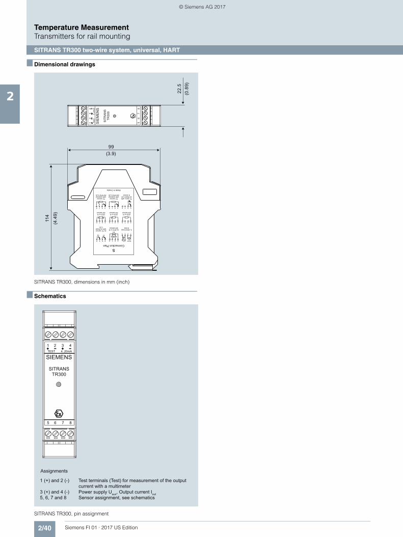
2/40 Siemens FI 01 · 2017 US Edition
Temperature MeasurementTransmitters for rail mounting
SITRANS TR300 two-wire system, universal, HART
2
■ Dimensional drawings
SITRANS TR300, dimensions in mm (inch)
■ Schematics
SITRANS TR300, pin assignment
5678 5678 5678
1
A
23
+UB - TEST+ -
4
56
S2
S1
785
S1S2
6
+ +
78
+
5678
+
5678
+
56
+
78
22.5
(0.8
9)
(3.9)99
114
(4.4
9)
SIE
ME
NS
SIT
RA
NS
TR
300
56
78
12
TES
T4.
.20m
A
34
sConnection Plan
4..20mA loop& test
2x RTD or R2W sensor
2x TC sensorwith int./fixed
CJC
RTD or R2W sensor
RTD or R3W sensor
RTD or R4W sensor
Made in Croatia
TC sens. withint./fixed CJC
U sensor
TC sensorwith external2W RTD CJC
TC sensorwith external3W RTD CJC
1 (+) and 2 (-) Test terminals (Test) for measurement of the output current with a multimeter3 (+) and 4 (-) Power supply Uaux, Output current Iout 5, 6, 7 and 8 Sensor assignment, see schematics
Assignments
SIEMENS
SITRANS TR300
5 6 7 8
1 2TEST 4..20mA
3 4
© Siemens AG 2017

2/41Siemens FI 01 · 2017 US Edition
Temperature MeasurementTransmitters for rail mounting
SITRANS TR300 two-wire system, universal, HART
2
SITRANS TR300, sensor connection assignment
++-- ++--
Current measurement Voltage measurement
Three-wire system
Four-wire system
Generation of averagevalue/difference 1)
Three-wire system
Four-wire system
Generation of averagevalue/difference 1)
Generation of average value / differencewith internal cold junction compensation
1) Programmable line resistance for the purpose of correction.
Test terminals
Resistance thermometer Resistance Thermocouple
Power supply/4 ... 20 mA (Uaux)
Two-wire system 1) Two-wire system 1) Cold junction compensationinternal/fixed value
Cold junction compensation withexternal Pt100 in two-wire system 1)
Cold junction compensation withexternal Pt100 in three-wire system
++--5 6 7 85 6 7 8
5 6 7 85 6 7 8
5 6 7 85 6 7 85 6 7 85 6 7 8 5 6 7 85 6 7 8
5 6 7 85 6 7 8 5 6 7 85 6 7 8
5 6 7 85 6 7 85 6 7 85 6 7 85 6 7 85 6 7 8
5 6 7 85 6 7 8 5 6 7 85 6 7 85 6 7 85 6 7 8
1 2 3 41 2 3 41 2 3 41 2 3 4
5 6 7 85 6 7 8
++--
++ --AA
RTD
R
RTD R
RTD
RTD1
RTD2
R
TC
TC
RTD
TC
RTD
+-
+-
+-
TC1 TC2
Uaux+ -
R
IU
R2R2
R1R1
© Siemens AG 2017
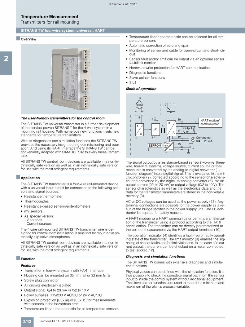
2/42 Siemens FI 01 · 2017 US Edition
Temperature MeasurementTransmitters for rail mounting
SITRANS TW four-wire system, universal, HART
2
■ Overview
The user-friendly transmitters for the control room
The SITRANS TW universal transmitter is a further development of the service-proven SITRANS T for the 4-wire system in a mounting rail housing. With numerous new functions it sets new standards for temperature transmitters.
With its diagnostics and simulation functions the SITRANS TW provides the necessary insight during commissioning and oper-ation. And using its HART interface the SITRANS TW can be conveniently adapted with SIMATIC PDM to every measurement task.
All SITRANS TW control room devices are available in a non-in-trinsically safe version as well as in an intrinsically safe version for use with the most stringent requirements.
■ Application
The SITRANS TW transmitter is a four-wire rail-mounted device with a universal input circuit for connection to the following sen-sors and signal sources:• Resistance thermometer• Thermocouples• Resistance-based sensors/potentiometers• mV sensors• As special version:
- V sources- Current sources
The 4-wire rail-mounted SITRANS TW transmitter wire is de-signed for control room installation. It must not be mounted in po-tentially explosive atmospheres.
All SITRANS TW control room devices are available in a non-in-trinsically safe version as well as in an intrinsically safe version for use with the most stringent requirements.
■ Function
Features• Transmitter in four-wire system with HART interface• Housing can be mounted on 35 mm rail or 32 mm G rail• Screw plug connector• All circuits electrically isolated• Output signal: 0/4 to 20 mA or 0/2 to 10 V• Power supplies: 115/230 V AC/DC or 24 V AC/DC• Explosion protection [EEx ia] or [EEx ib] for measurements
with sensors in the hazardous area• Temperature-linear characteristic for all temperature sensors
• Temperature-linear characteristic can be selected for all tem-perature sensors
• Automatic correction of zero and span• Monitoring of sensor and cable for open-circuit and short- cir-
cuit• Sensor fault and/or limit can be output via an optional sensor
fault/limit monitor• Hardware write protection for HART communication• Diagnostic functions• Slave pointer functions• SIL1
Mode of operation
The signal output by a resistance-based sensor (two-wire, three-wire, four-wire system), voltage source, current source or ther-mocouple is converted by the analog-to-digital converter (1, function diagram) into a digital signal. This is evaluated in the mi-crocontroller (2), corrected according to the sensor characteris-tic, and converted by the digital-to-analog converter (6) into an output current (0/4 to 20 mA) or output voltage (0/2 to 10 V). The sensor characteristics as well as the electronics data and the data for the transmitter parameters are stored in the non-volatile memory (3).
AC or DC voltages can be used as the power supply (13). Any terminal connections are possible for the power supply as a re-sult of the bridge rectifier in the power supply unit. The PE con-ductor is required for safety reasons.
A HART modem or a HART communicator permit parameteriza-tion of the transmitter using a protocol according to the HART specification. The transmitter can be directly parameterized at the point of measurement via the HART output terminals (10).
The operation indicator (4) identifies a fault-free or faulty operat-ing state of the transmitter. The limit monitor (9) enables the sig-naling of sensor faults and/or limit violations. In the case of a cur-rent output, the current can be checked on a meter connected to test socket (12).
Diagnosis and simulation functions
The SITRANS TW comes with extensive diagnosis and simula-tion functions.
Physical values can be defined with the simulation function. It is thus possible to check the complete signal path from the sensor input to inside the control system without additional equipment. The slave pointer functions are used to record the minimum and maximum of the plant’s process variable.
HART modem/ communicator
Current test0/4 ... 20 mA
OutputU or I
Powersup-ply
unit
EEPROM
73
13UH
A
D
6
5μC
A12
11
10
A
D
RTD
TC
1 2
9
48
© Siemens AG 2017
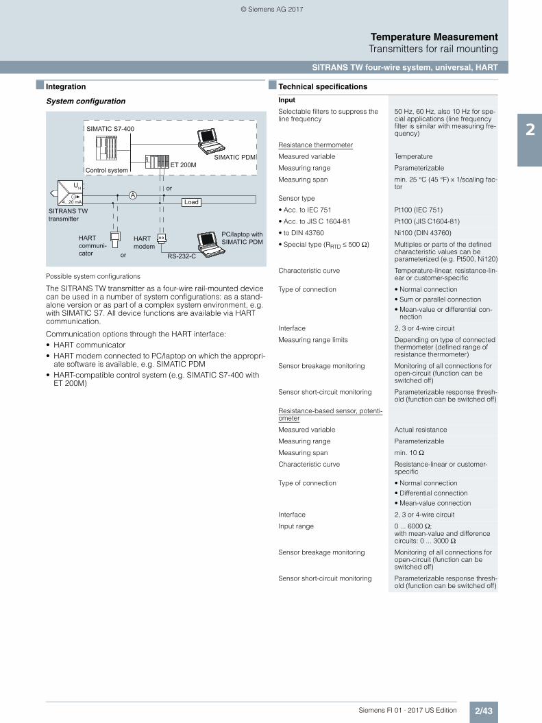
2/43Siemens FI 01 · 2017 US Edition
Temperature MeasurementTransmitters for rail mounting
SITRANS TW four-wire system, universal, HART
2
■ Integration
System configuration
Possible system configurations
The SITRANS TW transmitter as a four-wire rail-mounted device can be used in a number of system configurations: as a stand-alone version or as part of a complex system environment, e.g. with SIMATIC S7. All device functions are available via HART communication.
Communication options through the HART interface:• HART communicator• HART modem connected to PC/laptop on which the appropri-
ate software is available, e.g. SIMATIC PDM• HART-compatible control system (e.g. SIMATIC S7-400 with
ET 200M)
■ Technical specifications
SITRANS TWtransmitter
Control system
or
Load
HARTcommuni-cator or
HARTmodem
PC/laptop withSIMATIC PDM
AUH
RS-232-C
SIMATIC S7-400
ET 200MSIMATIC PDM
4...20 mA
Input
Selectable filters to suppress the line frequency
50 Hz, 60 Hz, also 10 Hz for spe-cial applications (line frequency filter is similar with measuring fre-quency)
Resistance thermometer
Measured variable Temperature
Measuring range Parameterizable
Measuring span min. 25 °C (45 °F) x 1/scaling fac-tor
Sensor type
• Acc. to IEC 751 Pt100 (IEC 751)
• Acc. to JIS C 1604-81 Pt100 (JIS C1604-81)
• to DIN 43760 Ni100 (DIN 43760)
• Special type (RRTD ≤ 500 Ω) Multiples or parts of the defined characteristic values can be parameterized (e.g. Pt500, Ni120)
Characteristic curve Temperature-linear, resistance-lin-ear or customer-specific
Type of connection • Normal connection• Sum or parallel connection• Mean-value or differential con-
nection
Interface 2, 3 or 4-wire circuit
Measuring range limits Depending on type of connected thermometer (defined range of resistance thermometer)
Sensor breakage monitoring Monitoring of all connections for open-circuit (function can be switched off)
Sensor short-circuit monitoring Parameterizable response thresh-old (function can be switched off)
Resistance-based sensor, potenti-ometer
Measured variable Actual resistance
Measuring range Parameterizable
Measuring span min. 10 Ω
Characteristic curve Resistance-linear or customer-specific
Type of connection • Normal connection• Differential connection• Mean-value connection
Interface 2, 3 or 4-wire circuit
Input range 0 ... 6000 Ω;with mean-value and difference circuits: 0 ... 3000 Ω
Sensor breakage monitoring Monitoring of all connections for open-circuit (function can be switched off)
Sensor short-circuit monitoring Parameterizable response thresh-old (function can be switched off)
© Siemens AG 2017
2/44 Siemens FI 01 · 2017 US Edition
Temperature MeasurementTransmitters for rail mounting
SITRANS TW four-wire system, universal, HART
2
Thermocouples
Measured variable Temperature
Measuring range Parameterizable
Measuring span min. 50 °C (90 °F) x 1/scaling fac-tor
Measuring range limits Depend. on type of thermocouple element
Thermocouple element Type B: Pt30 %Rh/Pt6 %Rh (DIN IEC 584)
Type C: W5 %-Re (ASTM 988)
Type D: W3 %-Re (ASTM 988)
Type E: NiCr/CuNi (DIN IEC 584)
Type J: Fe/CuNi (DIN IEC 584)
Type K: NiCr/Ni (DIN IEC 584)
Type L: Fe-CuNi (DIN 43710)
Type N: NiCrSi-NiSi (DIN IEC 584)
Type R: Pt13 %Rh/Pt (DIN IEC 584)
Type S: Pt10 %Rh/Pt (DIN IEC 584)
Type T: Cu/CuNi (DIN IEC 584)
Type U: Cu/CuNi (DIN 43710)
Special type (-10 mV ≤ UTC ≤ 100 mV)
Characteristic curve Temperature-linear, voltage-linear or customer-specific
Type of connection • Normal connection• Averaging connection• Mean-value connection• Differential connection
Cold junction compensation None, internal measurement, external measurement or pre-defined fixed value
Sensor breakage monitoring Function can be switched off
mV sensors
Measured variable DC voltage
Measuring range Parameterizable
Measuring span min. 4 mV
Input range -120 ... +1000mV
Characteristic curve Voltage-linear or customer-spe-cific
Overload capacity of inputs max. ± 3.5 V
Input resistance ≥ 1 MΩ
Sensor current Approx. 180 μA
Sensor breakage monitoring Function can be switched off
V sources
Measured variable DC voltage
Measuring range Parameterizable
Characteristic curve Voltage-linear or customer-spe-cific
Input range/min. span
• Devices with 7NG3242-xxxx1 or 7NG3242-xxxx0 with U/I plug
-1.2 ... + 10 V/0.04 V
• Devices with 7NG3242-xxxx2 -12 ... +100 V/0.4 V
• Devices with 7NG3242-xxxx3 -120 ... +140 V/4.0 V
Sensor breakage monitoring Not possible
μA-, mA sources
Measured variable DC voltage
Measuring range Parameterizable
Characteristic curve Current-linear or customer- specific
Input range/min. span
• Devices with 7NG3242-xxxx4 -12 ... +100 μA/0.4 μA
• Devices with 7NG3242-xxxx5 -120 ... +1000 μA/4 μA
• Devices with 7NG3242-xxxx6 -1.2 ... +10 mA/0.04 mA
• Devices with 7NG3242-xxxx7 or 7NG3242-xxxx0 with U/I plug
-12 ... +100 mA/0.4 mA
• Devices with 7NG3242-xxxx8 -120 ... +1000 mA/4 mA
Sensor breakage monitoring Not possible
Output
Output signal Load-independent direct current 0/4 ... 20 mA, can be switched to load-independent DC voltage 0/2 ... 10 V using plug-in jumpers
Current 0/4 ... 20 mA
• Overrange -0.5 ... +23.0 mA, continuously adjustable
• Output range following sensor fault (conforming to NE43)
-0.5 ... +23.0 mA, continuously adjustable
• Load ≤ 650 Ω
• No-load voltage ≤ 30 V
Voltage 0/2 ... 10 V
• Overrange -0.25 ... +10.75 V, continuously adjustable
• Output range following sensor fault
-0.25 ... +10.75 V, continuously adjustable
• Load resistance ≥ 1 kΩ
• Load capacitance ≤ 10 nF
• Short-circuit current ≤ 100 mA (not permanently short-circuit-proof)
• Electrical damping
- adjustable time constant T63 0 ... 100 s, in steps of 0.1 s
• Current source/voltage source Continuously adjustable within the total operating range
Sensor fault/limit signalling By operation indicator, relay out-put or HART interface
Operation indicator Flashing signal
• Limit violation Flashing frequency 5 Hz
• Sensor fault monitoring Flashing frequency 1 Hz
Relay outputs Either as NO or NC contact with 1 changeover contact
• Switching capacity ≤ 150 W, ≤ 625 VA
• Switching voltage ≤ 125 V DC, ≤ 250 V AC
• Switching current ≤ 2.5 A DC
Sensor fault monitoring Signalling of sensor or line break-age and sensor short-circuit
Limit monitoring
• Operating delay 0 ... 10 s
• Monitoring functions of limit module
• Sensor fault (breakage and/or short-circuit)
• Lower and upper limit• Window (combination of lower
and upper limits)• Limit and sensor fault detection
can be combined
• Hysteresis Parameterizable between 0 and 100 % of measuring range
© Siemens AG 2017

2/45Siemens FI 01 · 2017 US Edition
Temperature MeasurementTransmitters for rail mounting
SITRANS TW four-wire system, universal, HART
2
Auxiliary power
Universal power supply unit 115/230 V AC/DC or 24 V AC/DC
Tolerance range for power supply
• With 115/230 V AC/DC PSU 80 ... 300 V DC; 90 ... 250 V AC
• With 24 V AC/DC PSU 18 ... 80 V DC; 20.4 ... 55.2 V AC (in each case interruption-resis-tant up to 20 ms in the complete tolerance range)
Tolerance range for mains frequency 47 ... 63 Hz
Power consumption with
• 230 V AC ≤ 5 VA
• 230 V DC ≤ 5 W
• 24 V AC ≤ 5 VA
• 24 V DC ≤ 5 W
Electrically isolated
Electrically isolated circuits Input, output, power supply and sensor fault/limit monitoring out-put are electrically isolated from one another. The HART interface is electrically connected to the output.
Working voltage between all electri-cally isolated circuits
The voltage Urms between any two terminals must not exceed 300 V
Measuring accuracy
Accuracy
• Error in the internal cold junction ≤ 3 °C ± 0.1 °C / 10 °C (≤ 5.4 °F ± 0.18 °F / 18 °F)
• Error of external cold junction ter-minal 7NG3092-8AV
≤ 0.5 °C ± 0.1 °C / 10 °C(≤ 0.9 °F ± 0.18 °F / 18 °F)
• Digital output See "Digital error"
• Analog output IAN or UAN ≤ 0.05 % of the span plus digital error
Influencing effects (referred to the digital output)
Compared to the max. span:
• Temperature drift ≤ 0.08 % / 10 °C (≤ 0.08 % /18 °F)≤ 0.2 % in the range -10 ... +60 °C (14 ... 140 °F)
• Long-term drift ≤ 0.1 % / year
Influencing effects referred to the analog output IAN or UAN
Compared to the span:
• Temperature drift ≤ 0.08 % / 10°C (≤ 0.08 % / 18 °F)≤ 0.2 % in the range -10 ... +60 °C (14 ... 140 °F)
• Power supply ≤ 0.05 % / 10 V
• Load with current output ≤ 0.05 % on change from 50 Ω to 650 Ω
• Load with voltage output ≤ 0.1 % on change in the load current from 0 mA to 10 mA
• Long-term drift (start-of-scale val-ue, span)
≤ 0.03 % / month
Response time (T63 without electri-cal damping)
≤ 0.2 s
Electromagnetic compatibility According to EN 61 326 and NAMUR NE21
Certificates and approvals
ATEX To DIN EN 50014: 1997, EN 50020: 1994
Intrinsic safety to EN 50 020
• for 7NG3242-xAxxx II (1) G D [EEx ia/ib ] IIB
• for 7NG3242-xBxxx II (1) G D [EEx ia/ib ] IIC
EC type-examination certificate TÜV (German Technical Inspec-torate) 01 ATEX 1675
Other certificates GOST, NEPSI
Conditions of use
Installation conditions
Location (for devices with explosion protection)
• Transmitters Outside the potentially explosive atmosphere
• Sensor Within the potentially explosive atmosphere zone 1 (also in zone 0 in conjunction with the pre-scribed protection requirements for the sensor)
Ambient conditions
Permissible ambient temperature -25 ... +70 °C (-13 ... +158 °F)
Permissible storage temperature -40 ... +85 °C (-40 ... +185 °F)
Climatic class
• Relative humidity 5 ... 95 %, no condensation
Design
Weight Approx. 0.24 kg (0.53 lb)
Enclosure material PBT, glass-fibre reinforced
Degree of protection to IEC 529 IP20
Degree of protection to VDE 0100 Protection class I
Type of installation 35-mm DIN rail (1.38 inch)(EN 50022) or 32-mm G-type rail (1.26 inch) (EN 50035)
Electrical connection / process con-nection
Screw plug connectors, max. 2.5 mm² (0.01 inch²)
Parameterization interface
Protocol HART, version 5.9
Load with connection of
• HART communicator 230 ... 650 Ω
• HART modem 230 ... 500 Ω
Software for PC/laptop SIMATIC PDM version V5.1 and later
© Siemens AG 2017
2/46 Siemens FI 01 · 2017 US Edition
Temperature MeasurementTransmitters for rail mounting
SITRANS TW four-wire system, universal, HART
2
Digital error
Resistance thermometer
Resistance-based sensors
Thermocouples
1) Accuracy data refer to the largest error in the complete measuring range
Voltage/current sources
Input Measuring range Max. permissi-ble line resis-tance
Digital error
°C / (°F) Ω °C / (°F)
IEC 751
• Pt10 -200 ... +850(-328 ... +1562)
20 3.0 (5.4)
• Pt50 -200 ... +850(-328 ... +1562)
50 0.6 (1.1)
• Pt100 -200 ... +850(-328 ... +1562)
100 0.3 (0.5)
• Pt200 -200 ... +850(-328 ... +1562)
100 0.6 (1.1)
• Pt500 -200 ... +850(-328 ... +1562)
100 1.0 (1.8)
• Pt1000 -200 ... +850(-328 ... +1562)
100 1.0 (1.8)
JIS C 1604-81
• Pt10 -200 ... +649(-328 ... +1200)
20 3.0 (5.4)
• Pt50 -200 ... +649(-328 ... +1200)
50 0.6 (1.1)
• Pt100 -200 ... +649(-328 ... +1200)
100 0.3 (0.5)
DIN 43760
• Ni50 -60 ... +250(-76 ... +482)
50 0.3 (0.5)
• Ni100 -60 ... +250(-76 ... +482)
100 0.3 (0.5)
• Ni120 -60 ... +250(-76 ... +482)
100 0.3 (0.5)
• Ni1000 -60 ... +250(-76 ... +482)
100 0.3 (0.5)
Input Measuring range
Max. permissi-ble line resis-tance
Digital error
Ω Ω Ω
Resistance(linear)
0 ... 24 5 0.08
0 ... 47 15 0.06
0 ... 94 30 0.06
0 ... 188 50 0.08
0 ... 375 100 0.1
0 ... 750 100 0.2
0 ... 1500 75 1.0
0 ... 3000 100 1.0
0 ... 6000 100 2.0
Input Measuring range Digital error1)
°C / (°F) °C (°F)
Type B 0 ... +1820(+32 ... +3308)
3 (5.4)
Type C 0 ... +2300(+32 ... +4172)
2 (3.6)
Type D 0 ... +2300(+32 ... +4172)
1 (1.8)
Type E -200 ... +1000(-328 ... +1832)
1 (1.8)
Type J -210 ... +1200(-346 ... +2192)
1 (1.8)
Type K -200 ... +1372(-328 ... +2501)
1 (1.8)
Type L -200 ... +900(-328 ... +1652)
2 (3.6)
Type N -200 ... +1300(-328 ... +2372)
1 (1.8)
Type R -50 ... +1760(-58 ... +3200)
2 (3.6)
Type S -50 ... +1760(-58 ... +3200)
2 (3.6)
Type T -200 ... +400(-328 ... +752)
1 (1.8)
Type U -200 ... +600(-328 ... +1112)
2 (3.6)
Input Measuring range Digital error
mV sources (linear) mV μV
-1 ... +16 35
-3 ... +32 20
-7 ... +65 20
-15 ... +131 50
-31 ... +262 100
-63 ... +525 200
-120 ... +1000 300
V sources (linear) V mV
-1.2 ... +10 3
-12 ... +100 30
-120 ... +140 300
μA/mA sources(linear)
μA/mA μA
-12 ... +100 μA 0.05
-120 ... +1000 μA 0.5
-1.2 ... +10 mA 5
-12 ... + 100 mA 50
-120 ... +1000 mA 500
© Siemens AG 2017
2/47Siemens FI 01 · 2017 US Edition
Temperature MeasurementTransmitters for rail mounting
SITRANS TW four-wire system, universal, HART
2
■ Ordering examples ■ Ordering information
The article number structure shown below is used to specify a fully functioning transmitter. The selection of the operating data (type of source, measuring range, characteristic etc.) is made according to the following rules:• Operating data already set in factory to default values:
The default settings can be obtained from the list of parame-terizable operating data (see "Special operating data"). The presets can be modified by the customer to match the require-ments precisely.
• Operating data set on delivery according to customer require-ments:Supplement the Article No. by "-Z" and add the Order code "Y01". The operating data to be set can be obtained from the list of parameterize operating data. The Order codes A 7 7 to K 7 7 for operating data to be set need only be specified in the order if they deviate from the default setting.The default setting is used if no Order code is specified for op-erating data.
The selected parameters are printed on the transmitter's rating plate.
Desired transmitter Parameter: Ordering design
Standard Special
Example 1:SITRANS TW, transmitter in four-wire system
7NG
3242
-1A
A00
(sto
ck it
em)
• with explosion protection ATEX• 230 V AC/DC power supply• current output• without sensor fault/limit monitor
- Sensor PT100, three-wire circuit X- Measuring range 0 ... 150 °C X- Temperature-linear characteristic X- Filter time 1 s X- Output 4 ... 20 mA, line filter 50 Hz X- Output driven to full-scale in event
of like breakageX
Example 2:SITRANS TW, transmitter in four-wire system
7NG
3242
-0B
B10
-ZY
01 +
S76
+ A
05 +
Y30
+ H
10Y
01: s
ee O
rder
cod
eY
30: M
A=
0; M
E=
950
; D=
C• without explosion protection• 24 V AC/DC power supply• Voltage output• Sensor fault/limit monitor
- Rating plate in English S76- Sensor NiCr/Ni, type K A05- Cold junction internal X- Measuring range 0 ... 950 °C Y30- Temperature-linear characteristic X- Filter time 1 s X- Output 0 ... 10 V, line filter 50 Hz H10- Output driven to full-scale in event
of like breakageX
- Limit monitoring switched off X
Example 3:SITRANS TW, transmitter in four-wire system
7NG
3242
-0B
A01
-ZY
01 +
A40
+ Y
32 +
G07
+ H
11 +
J03
Y01
: see
Ord
er c
ode
Y32
: MA
=0;
ME
= 5
; D=
V
• without explosion protection• 24 V AC/DC power supply• Current output• without sensor fault/limit monitor
- Voltage input, measuringrange -1.2 V ... +10 V
A40
- Measuring range 0 ... 5 V Y32- Source-proportional characteristic X- Filter time 10 s G07- Output 0 ... 20 mA, line filter 60 Hz H11- No monitoring for sensor fault (X) J03
© Siemens AG 2017
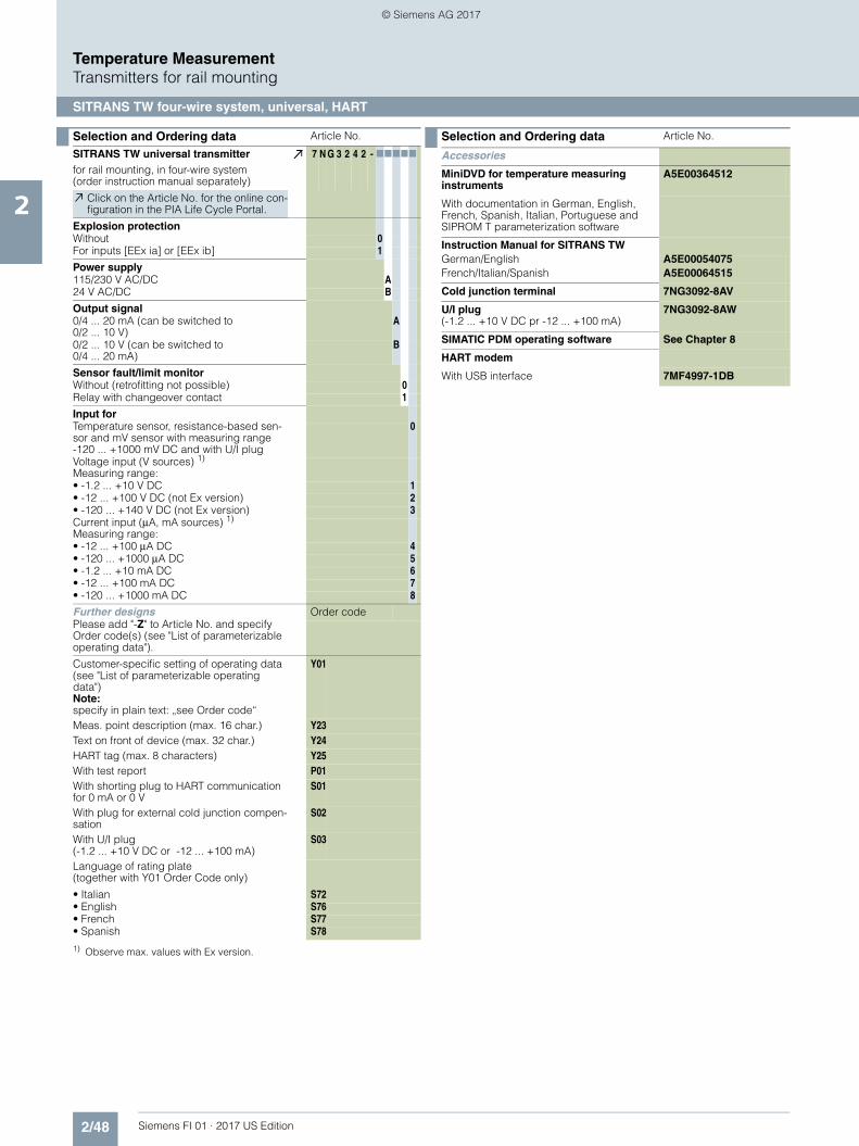
2/48 Siemens FI 01 · 2017 US Edition
Temperature MeasurementTransmitters for rail mounting
SITRANS TW four-wire system, universal, HART
2
Selection and Ordering data Article No.
SITRANS TW universal transmitterfor rail mounting, in four-wire system (order instruction manual separately)
7 N G 3 2 4 2 - 77777
Click on the Article No. for the online con-figuration in the PIA Life Cycle Portal.
Explosion protectionWithout 0For inputs [EEx ia] or [EEx ib] 1
Power supply115/230 V AC/DC A24 V AC/DC B
Output signal0/4 ... 20 mA (can be switched to 0/2 ... 10 V)
A
0/2 ... 10 V (can be switched to 0/4 ... 20 mA)
B
Sensor fault/limit monitorWithout (retrofitting not possible) 0Relay with changeover contact 1
Input forTemperature sensor, resistance-based sen-sor and mV sensor with measuring range-120 ... +1000 mV DC and with U/I plug
0
Voltage input (V sources) 1)
Measuring range:
1) Observe max. values with Ex version.
• -1.2 ... +10 V DC 1• -12 ... +100 V DC (not Ex version) 2• -120 ... +140 V DC (not Ex version) 3Current input (μA, mA sources) 1)
Measuring range:• -12 ... +100 μA DC 4• -120 ... +1000 μA DC 5• -1.2 ... +10 mA DC 6• -12 ... +100 mA DC 7• -120 ... +1000 mA DC 8
Further designs Order codePlease add "-Z" to Article No. and specify Order code(s) (see "List of parameterizable operating data").
Customer-specific setting of operating data(see "List of parameterizable operating data")Note:specify in plain text: „see Order code“
Y01
Meas. point description (max. 16 char.) Y23Text on front of device (max. 32 char.) Y24HART tag (max. 8 characters) Y25With test report P01With shorting plug to HART communication for 0 mA or 0 V
S01
With plug for external cold junction compen-sation
S02
With U/I plug(-1.2 ... +10 V DC or -12 ... +100 mA)
S03
Language of rating plate (together with Y01 Order Code only)
• Italian S72• English S76• French S77• Spanish S78
Selection and Ordering data Article No.
Accessories
MiniDVD for temperature measuring instruments
A5E00364512
With documentation in German, English, French, Spanish, Italian, Portuguese and SIPROM T parameterization software
Instruction Manual for SITRANS TWGerman/English A5E00054075French/Italian/Spanish A5E00064515
Cold junction terminal 7NG3092-8AV
U/I plug(-1.2 ... +10 V DC pr -12 ... +100 mA)
7NG3092-8AW
SIMATIC PDM operating software See Chapter 8
HART modem
With USB interface 7MF4997-1DB
© Siemens AG 2017

2/49Siemens FI 01 · 2017 US Edition
Temperature MeasurementTransmitters for rail mounting
SITRANS TW four-wire system, universal, HART
2
■ List of parameterizable operating data (Order codes A 7 7 + B 7 7 ... E 7 7)
Operating data acc. to default setting Article No. with Order code: 7NG3242 - 7 7 7 7 7 -Z Y01
Order codes: A 7 7 ... E 7 7 777 + 777 + 777 + 777 + 777
Sensor
Thermocouples Connection Cold junction compensation
Measuring rangesType Temperature range
B: Pt30 %Rh/Pt6 %Rh 0 ... 1820 °C A 0 0 Standard B 0 1 None C 0 0 -30 ... +60 °C-20 ... +20 °C0 ... 40 °C0 ... 60 °C0 ... 80 °C0 ... 100 °C0 ... 120 °C
EEE
EEE
E
000
000
0
012
345
6
C:W5 %Re 0 ... 2300 °C A 0 1 Sum n 1) n = 2 B 0 2 Internal C 1 0D:W3 %Re 0 ... 2300 °C A 0 2 ... . . . Fixed val. 0 °C C 2 0E:NiCr/CuNi -200 ... +1000 °C A 0 3 n = 10 B 1 0 20 °C C 2 2J:Fe/CuNi (IEC) -210 ... +1200 °C A 0 4 Difference 2) Diff1 B 3 1 50 °C C 2 5K:NiCr/Ni -200 ... +1372 °C A 0 5 Diff2 B 3 2 60 °C C 2 6
L: Fe/CuNi (DIN) -200 ... +900 °C A 0 6 Mean-val. 2) MW B 4 1 70 °C C 2 7N:NiCrSi/NiSi -200 ... +1300 °C A 0 7 Special value 7) Y 1 0 0 ... 150 °C E 0 7R:Pt13 %Rh/Pt -50 ... +1760 °C A 0 8 External meas.
(through Pt100 DIN IEC 751) 7)
Y 1 1 0 ... 200 °C0 ... 250 °C0 ... 300 °C0 ... 350 °C0 ... 400 °C0 ... 450 °C0 ... 500 °C0 ... 600 °C0 ... 700 °C0 ... 800 °C0 ... 900 °C0 ... 1000 °C0 ... 1200 °C0 ... 1400 °C0 ... 1600 °C0 ... 1800 °C50 ... 100 °C50 ... 150 °C100 ... 200 °C100 ... 300 °C100 ... 400 °C200 ... 300 °C200 ... 400 °C200 ... 500 °C300 ... 600 °C500 ... 1000 °C600 ... 1200 °C800 ... 1600 °CSpecial range 7)
E
EEE
EEE
EEE
EEE
EEE
EE
EEE
EEE
E
E
E
E
Y
0
011
111
111
112
222
22
222
233
3
3
3
3
3
8
901
234
567
890
123
45
678
901
2
3
4
5
0
S:Pt10 %Rh/Pt -50 ... +1760 °C A 0 9T:Cu/CuNi (IEC) -200 ... +400 °C A 1 0U:Cu/CuNi (DIN) -200 ... +600 °C A 1 1
Resistance thermometer(or max. permissible line resistance see „Technical specifications“)
Connection Connection Line resis-tance 3)
Pt100 (DIN IEC) -200 ... +850 °C A 2 0 Standard B 0 1 2-wire-system C 3 2 0 Ω D 0 0Pt100 (JIS) -200 ... +649 °C A 2 1 Sum n 4) n = 2 B 0 2 3-wire-system C 3 3 10 Ω D 1 0Ni100 (DIN) -60 ... +250 °C A 2 2 ... . . . 4-wire-system C 3 4 20 Ω D 2 0
n = 10 B 1 0 50 Ω D 5 0Parallel n 5) n = 0.1 B 2 1 Special val.7) Y 2 0
n= 0.2 B 2 2n= 0.5 B 2 5
Special value 6) 7) Y 0 0Difference 2) Diff1 B 5 1
Diff2 B 5 2Mean-val. 2) MW B 6 1
Resistance-based sensors, potentiome-ters
Connection Connection Line resis-tance 3)
Measuring ranges
(or max. permissible line resistance see „Technical specifications“)
A 3 0 Standard B 0 1 2-wire-system C 3 2 0 Ω D 0 0 0 ... 100 Ω E 4 0Difference 2) Diff1 B 5 1 3-wire-system C 3 3 10 Ω D 1 0 0 ... 200 Ω E 4 1
Diff2 B 5 2 4-wire-system C 3 4 20 Ω D 2 0 0 ... 500 Ω E 4 2Mean val.2) MW B 6 1 50 Ω D 5 0 0 ... 1000 Ω E 4 3
Special val. 7) Y 2 0 0 ... 2500 Ω E 4 40 ... 5000 Ω 8) E 4 50 ... 6000 Ω 8) E 4 6Special range 7) Y 3 1
mV, V and μA, mA sensors 9) A 4 0 Meas. range with Article No. 7NG 3242 - 7 7 777 -Z Y01 E 5 0
0 -120 ... +1000 mV
1) n = number of thermocouple elements to be connected in series2) See „Circuit diagrams“ for meaning of type circuit3) Line resistance of channels 1 and 2, for max. permissible line resistance see
„Technical specifications“ (only with C32, not with C33 and C34)4) n = number of resistance thermometers to be connected in series5) 1/n = number of resistance thermometers to be connected in parallel6) Combination of series and parallel connection of resistance thermometers7) Operating data: see „Special operating data“8) This range does not apply to mean-value and difference circuits.9) The max. permissible currents and voltages according to conformity certifi-
cate must be observed in devices with explosion protection.10) Without detection of line breakage
1 -1,2 ... +10 V 10)
2 -12 ... +100 V 10)
3 -120 ... +140 V 10)
4 -12 ... +100 μA 10)
5 -120 ... +1000 μA 10)
6 -1,2 ... +10 mA 10)
7 -12 ... +100 mA 10)
8 -120 ... +1000 mA 10)
Special range 7) Y 3 2
© Siemens AG 2017

2/50 Siemens FI 01 · 2017 US Edition
Temperature MeasurementTransmitters for rail mounting
SITRANS TW four-wire system, universal, HART
2
■ List of parameterizable operating data (Order codes F 7 7 ... K 7 7)
Operating data according to default setting Article No. with Order code: 7NG3242 - 7 7 7 7 7 -Z Y01Order codes: F 7 7 ... K 7 7 777 + 777 + 777 + 777 + 777
Sensor
Thermocouple elements Voltage measure-ment
Filter time1)
Output sig-nal and line filter 2)
Failure signal Limit monitor 3)
Type Temperature range
B: Pt30 %Rh/ 0 ... 1820 °C A 0 0 Temperature-linear
F 0 0 0 s G 0 0 4 ... 20 mA/2 ... 10 Vwith line filter:
with line break-age/fault:
Limit monitor-ing ineffective (but sensor fault signalling with closed-circuit opera-tion)
K 0 0C:W5 %Re 0 ... 2300 °C A 0 1 0.1 s G 0 1D:W3 %Re 0 ... 2300 °C A 0 2 Voltage-
linearF 1 0 0.2 s G 0 2
E:NiCr/CuNi -200 ... +1000 °C A 0 3 0.5 s G 0 3 50 Hz H 0 0 to full scale J 0 0J:Fe/CuNi (IEC) -210 ... +1200 °C A 0 4 1 s G 0 4 60 Hz H 0 1 to start of scale J 0 1K:NiCr/Ni -200 ... +1372 °C A 0 5 2 s G 0 5 10 Hz 4) H 0 2 hold last value J 0 2
L: Fe/CuNi (DIN) -200 ... +900 °C A 0 6 5 s G 0 6 0 ... 20 mA/0 ... 10 Vwith line filter:
N:NiCrSi/NiSi -200 ... +1300 °C A 0 7 10 s G 0 7 no monitoring J 0 3R:Pt13 %Rh/Pt -50 ... +1760 °C A 0 8 20 s G 0 8 Effective 5) Y 7 0S:Pt10 %Rh/Pt -50 ... +1760 °C A 0 9 50 s G 0 9 50 Hz H 1 0 Safety value 5) Y 6 0T:Cu/CuNi (IEC) -200 ... +400 °C A 1 0 100 s G 1 0 60 Hz H 1 1U:Cu/CuNi (DIN) -200 ... +600 °C A 1 1 Special
time 5)Y 5 0 10 Hz H 1 2
Resistance thermometer(max. permissible line resistances see „Technical specifications“)
Voltage measure-ment
Filter time1)
same as for thermocou-ple ele-ments
Output sig-nal and line filter 2)
same as for thermocou-ple elements
Failure signal Limit monitor 3)
same as for thermocouple elements
Pt100 (DIN IEC) -200 ... +850 °C A 2 0 Temperature-linear
F 0 0 with line break-age/fault:Pt100 (JIS) -200 ... +649 °C A 2 1
Ni100 (DIN) -60 ... +250 °C A 2 2 Resistance-linear
F 2 0 to full scale J 0 0to start of scale J 0 1hold last value J 0 2
no monitoring J 0 3
Safety value 5) Y 6 0
with line break-age or short-cir-cuit/fault:to full scale J 1 0to start of scale J 1 1hold last value J 1 2
no monitoring J 1 3
Safety value 5) Y 6 1
Resistance-based sensors, potenti-ometers
Voltage measure-ment
Filter time1)
same as for thermocou-ple ele-ments
Output sig-nal and line filter 2)
same as for thermocou-ple elements
Failure signal Limit monitor 3)
same as for thermocouple elements
(max. permissible line resistances see „Technical specifications“)
A 3 0 Resistance-linear
F 2 0 with line break-age/fault:to full scale J 0 0to start of scale J 0 1hold last value J 0 2
no monitoring J 0 3
Safety value 5) Y 6 0
mV, V and μA, mA sources A 4 0 Voltage measure-ment
Filter time1)
same as for thermocou-ple ele-ments
Output sig-nal and line filter 2)
same as for thermocou-ple elements
Limit monitor 3)
same as for thermocouple elements
Source pro-portional
F 3 0
1) Software filter to smooth the result2) Filter to suppress line disturbances on the measured signal.3) If signalling relay present4) for special appliciations5) Operating data: see „Special operating data“
© Siemens AG 2017

2/51Siemens FI 01 · 2017 US Edition
Temperature MeasurementTransmitters for rail mounting
SITRANS TW four-wire system, universal, HART
2
■ Special operating data
Ordercode
Plain text required
Options
Y00 N=. Factor N for multiplication with the charac-teristic values of resistance thermometersRange of values: 0.10 to 10.001. Example: 3 x Pt500 parallel: N = 5/3 = 1.667; 2. Example: Ni120: N = 1.2
Y10 TV=. Temperature TV of the fixed cold junctionD= Dimension; range of values: C, K, F, R
Y11 RL=. Line resistance RL in Ω for compensation of cold junction line of external Pt100 DIN IEC 751 Range of values: 0.00 to 100.00
Y20 RL1=.RL2=.
Line resistances RL of channel 1 (RL1) and channel 2 (RL2) in Ω if the resistance ther-mometer or the resistance-based sensor is connected in a two-wire system Range of values depending on type of sen-sor: 0.00 to 100.00
Y30 MA=.ME=.
Start-of-scale value MA and full-scale value ME for thermocouples and resistance ther-mometers(Range of values depending on type of sen-sor)
D= Dimension, range of values: C, K, F, R)Y31 MA=.
ME=.Start-of-scale value MA and full-scale value ME for resistance-based sensors or potenti-ometers in ΩRange of values: 0.00 to 6,000.00
Y32 MA=.ME=.
D=
Start-of-scale value MA and full-scale value ME for mV, V, µA and mA sourcesRange of values depending on type of sen-sor: -120.00 to 1,000.00 Dimension (mV entered as MV, V as V, µA as UA, mA as MA)
Y50 T63=. Response time T63 of software filter in sRange of values: 0.0 to 100.0Safety value S of signal output in mA or in V corresponding to the set type of output. Range of values- with current output: -0.50 to 23.00- with voltage output: -0.25 to 10.75
Y60 S=. Safety value S with line breakage of sensorY61 S=. Safety value S with line breakage or short-
circuit of sensorY70 UG=.
OG=.
H=.
K=
A=
T=.
Lower limit value (dimension as defined by measuring range)Upper limit value (dimension as defined by measuring range)Hysteresis (dimension as defined by mea-suring range)Switch on/off combination of limit function and sensor fault detection; J=on; N=off (standard: J)Type of relay output: A=open-circuit opera-tion; R=closed-circuit operation (standard: R)Switching delay T of relay output in sRange of values: 0.0 to 10.0 (standard: 0.0)
© Siemens AG 2017
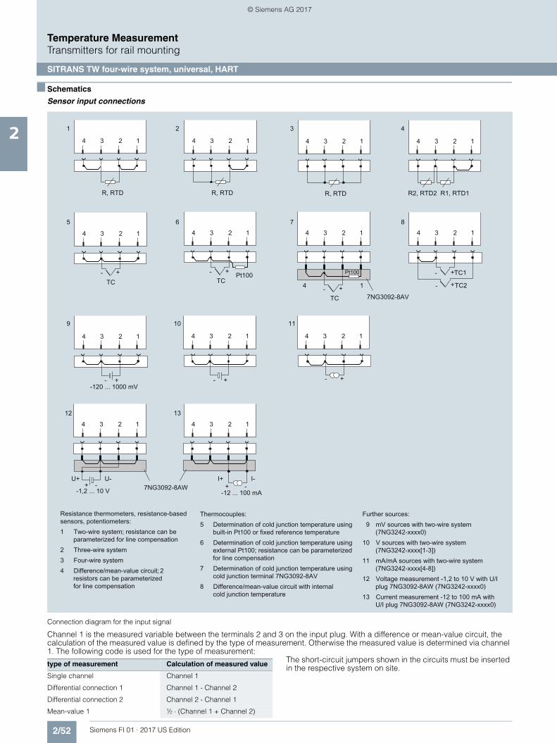
2/52 Siemens FI 01 · 2017 US Edition
Temperature MeasurementTransmitters for rail mounting
SITRANS TW four-wire system, universal, HART
2
■ Schematics
Sensor input connections
Connection diagram for the input signal
Channel 1 is the measured variable between the terminals 2 and 3 on the input plug. With a difference or mean-value circuit, the calculation of the measured value is defined by the type of measurement. Otherwise the measured value is determined via channel 1. The following code is used for the type of measurement: The short-circuit jumpers shown in the circuits must be inserted
in the respective system on site.type of measurement Calculation of measured value
Single channel Channel 1
Differential connection 1 Channel 1 - Channel 2
Differential connection 2 Channel 2 - Channel 1
Mean-value 1 ½ ⋅ (Channel 1 + Channel 2)
© Siemens AG 2017

2/53Siemens FI 01 · 2017 US Edition
Temperature MeasurementTransmitters for rail mounting
SITRANS TW four-wire system, universal, HART
2
Connection diagram for power supply, input and outputs
Relay outputs
■ Dimensional drawings
Dimensions for control room mounting, rail mounting in mm (inches)
Connected terminals
Closed-circuit operation (relay opens when error)
• Device switched off 10 and 11
• Device switched on and no error 9 and 11
• Device switched on and error 10 and 11
Open-circuit operation (relay closes when error)
• Device switched off 10 and 11
• Device switched on and no error 10 and 11
• Device switched on and error 9 and 11
1 to 4 Signal input (see "sensor input connections" for possible types of connection)
5, 6 Analog output (U or I output parameterizable using plug-in jumpers)
7, 8 Connection with HART communication for local parameterization
9 to 11 Output for sensor fault/limit monitor as relay contact (see below for possible parameterization)12 PE connection13, 14 Power supply input (protected against reverse polarity)
Relay output HART
SensorLimitmonitor
HART/Power supplyconnection
14 13 12 11 10 9 8 7 6 5 4 3 2 1
UH+ -+ -~ ~
1
1 In devices with explosion protection
112.5 (4.43) 26.6 (1.04)
114
(4.5
)
135 (5.3)
12 (0.47) 38 (1.5)
© Siemens AG 2017

2/54 Siemens FI 01 · 2017 US Edition
Temperature MeasurementTransmitters for field mounting
SITRANS TF280 WirelessHART
2
■ Overview
SITRANS TF280 for flexible and cost-effective temperature mea-surements• Supports the WirelessHART standard (HART V 7.1)• Very high security level for wireless data transmission• Built-in local user interface (LUI) with 3-button operation• Optimum representation and readability using graphical dis-
play (104 x 80 pixels) with integrated backlight• Stand-by (deep sleep phase) mode can be turned on and off
with push of a button• Battery power supply• Battery life time up to 5 years• Extend battery life time with HART modem interface which can
be switch off• Optimized power consumption through new design, and in-
crease in battery life time• Simple configuration thanks to SIMATIC PDM• Housing meets IP65 degree of protection• Supports all Pt100 sensors as per IEC 751/DIN EN 60751
■ Benefits
The SITRANS TF280 is a temperature transmitter that features WirelessHART as the standard communication interface.
Also available is a wired interface to connect a HART modem:• Flexible temperature measurement• Save costs on wiring at difficult installation conditions. Wire-
less technology offers cost advantages in cases where exten-sive wiring costs would normally apply.
• It enables additional hitherto unfeasible measuring points, particularly for monitoring purposes
• Easy installation also on moveable equipment parts• Enables cost-effective temporary measurements, for example
for process optimizations.• Optimum solution in addition to wired communication and for
system solutions in process automation
■ Application
The SITRANS TF280 is a WirelessHART field device for tempera-ture measurement with a Pt100 sensor.
This sensor can be installed directly on the field device, or con-nected at an offset with a cable connection. On the wireless communication side, the transmitter supports the WirelessHART standard. A HART modem can be connected to the transmitter particularly for initial parameterization. Alternatively the device can be commissioned comfortably by means of the local push-buttons w/o any additional handset devices.
It can be used in all industries and applications in non-explosive areas.
■ Design
The SITRANS TF280 has a robust aluminum enclosure and is suitable for outside use. It conforms with the IP65 safety class.
The operation temperature range is -40 to +80 °C(-40 to +176 °F). Power supply is provided through an integrated battery, which is available as an accessory. The device is only approved for operation with this battery.
The antenna features a rotatable joint which can be used for directional alignment. Wireless signals can thus be optimallyreceived and transmitted.
A special highlight is the possibility to operate directly on thedevice with 3 push buttons. It perfectly matches the strategy of all new Siemens field devices.
Using the device’s push buttons, it is easy to turn the HART modem interface of the device on and off. The device can be put to passive status and reactivated at any time. This helps to extend the life time of the battery.
The SITRANS TF280 transmitter features a cable gland or a Pt100 sensor including protective piping.
■ Function
The SITRANS TF280 can join to a WirelessHART network. It can be parameterized and operated through this network. Measured process values are transmitted via the network to the SIEMENS IE/WSN-PA LINK.
Field device data received by the IE/WSN-PA LINK is transmitted to the connected systems, for example the process control sys-tem SIMATIC PCS 7. For an introduction of WirelessHART, please see the FI 01 catalogue Sec. 8 or www.siemens.com/wirelesshart.
Detailed information on IE/WSN-PA LINK can be found in the FI 01 catalogue Sec. 7 or www.siemens.com/wirelesshart.
■ Integration
Connecting to SIMATIC PCS 7
The integration of field devices in SIMATIC PCS 7 and other pro-cess control systems can be now done seamlessly and cost-ef-fectively with wireless technology, especially in situations where high wiring costs may be expected. Of particular interest are measuring points which are to be added and for which no wiring is available.
Where larger distances between the IE/WSN-PA LINK and con-trol systems need to be overcome, this connection can also be implemented on a wireless and cost-effective basis using the SCALANCE W series of products. Siemens WirelessHART de-vices operate with optimum coexistence to SCALANCE W family products.
© Siemens AG 2017
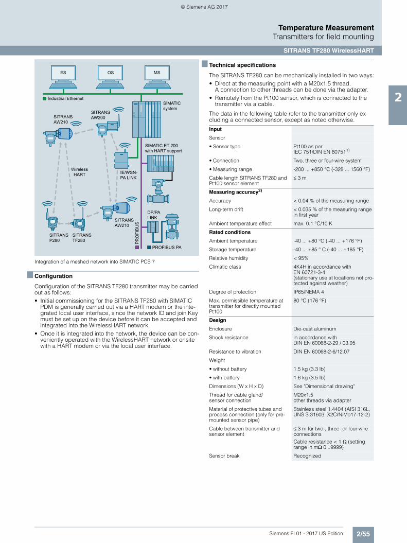
2/55Siemens FI 01 · 2017 US Edition
Temperature MeasurementTransmitters for field mounting
SITRANS TF280 WirelessHART
2
Integration of a meshed network into SIMATIC PCS 7
■ Configuration
Configuration of the SITRANS TF280 transmitter may be carried out as follows:• Initial commissioning for the SITRANS TF280 with SIMATIC
PDM is generally carried out via a HART modem or the inte-grated local user interface, since the network ID and join Key must be set up on the device before it can be accepted and integrated into the WirelessHART network.
• Once it is integrated into the network, the device can be con-veniently operated with the WirelessHART network or onsite with a HART modem or via the local user interface.
■ Technical specifications
The SITRANS TF280 can be mechanically installed in two ways:• Direct at the measuring point with a M20x1.5 thread.
A connection to other threads can be done via the adapter.• Remotely from the Pt100 sensor, which is connected to the
transmitter via a cable.
The data in the following table refer to the transmitter only ex-cluding a connected sensor, except as noted otherwise.
SIMATIC system
SIMATIC ET 200 with HART support
ES OS MS
IE/WSN-PA LINK
SITRANSAW210
SITRANSAW200
SITRANS AW210
SITRANS TF280
SITRANS P280
DP/PA LINK
Industrial Ethernet
PR
OFI
BU
S
Wireless HART
PROFIBUS PA
Input
Sensor
• Sensor type Pt100 as per IEC 751/DIN EN 607511)
• Connection Two, three or four-wire system
• Measuring range -200 ... +850 °C (-328 ... 1560 °F)
Cable length SITRANS TF280 and Pt100 sensor element
≤ 3 m
Measuring accuracy2)
Accuracy < 0.04 % of the measuring range
Long-term drift < 0.035 % of the measuring range in first year
Ambient temperature effect max. 0.1 °C/10 K
Rated conditions
Ambient temperature -40 ... +80 °C (-40 ... +176 °F)
Storage temperature -40 ... +85 ° C (-40 ... +185 °F)
Relative humidity < 95%
Climatic class 4K4H in accordance with EN 60721-3-4(stationary use at locations not pro-tected against weather)
Degree of protection IP65/NEMA 4
Max. permissible temperature at transmitter for directly mounted Pt100
80 °C (176 °F)
Design
Enclosure Die-cast aluminum
Shock resistance in accordance with DIN EN 60068-2-29 / 03.95
Resistance to vibration DIN EN 60068-2-6/12.07
Weight
• without battery 1.5 kg (3.3 lb)
• with battery 1.6 kg (3.5 lb)
Dimensions (W x H x D) See "Dimensional drawing"
Thread for cable gland/sensor connection
M20x1.5other threads via adapter
Material of protective tubes and process connection (only for pre-mounted sensor pipe)
Stainless steel 1.4404 (AISI 316L, UNS S 31603, X2CrNiMo17-12-2)
Cable between transmitter and sensor element
≤ 3 m für two-, three- or four-wire connectionsCable resistance < 1 Ω (setting range in mΩ 0...9999)
Sensor break Recognized
© Siemens AG 2017
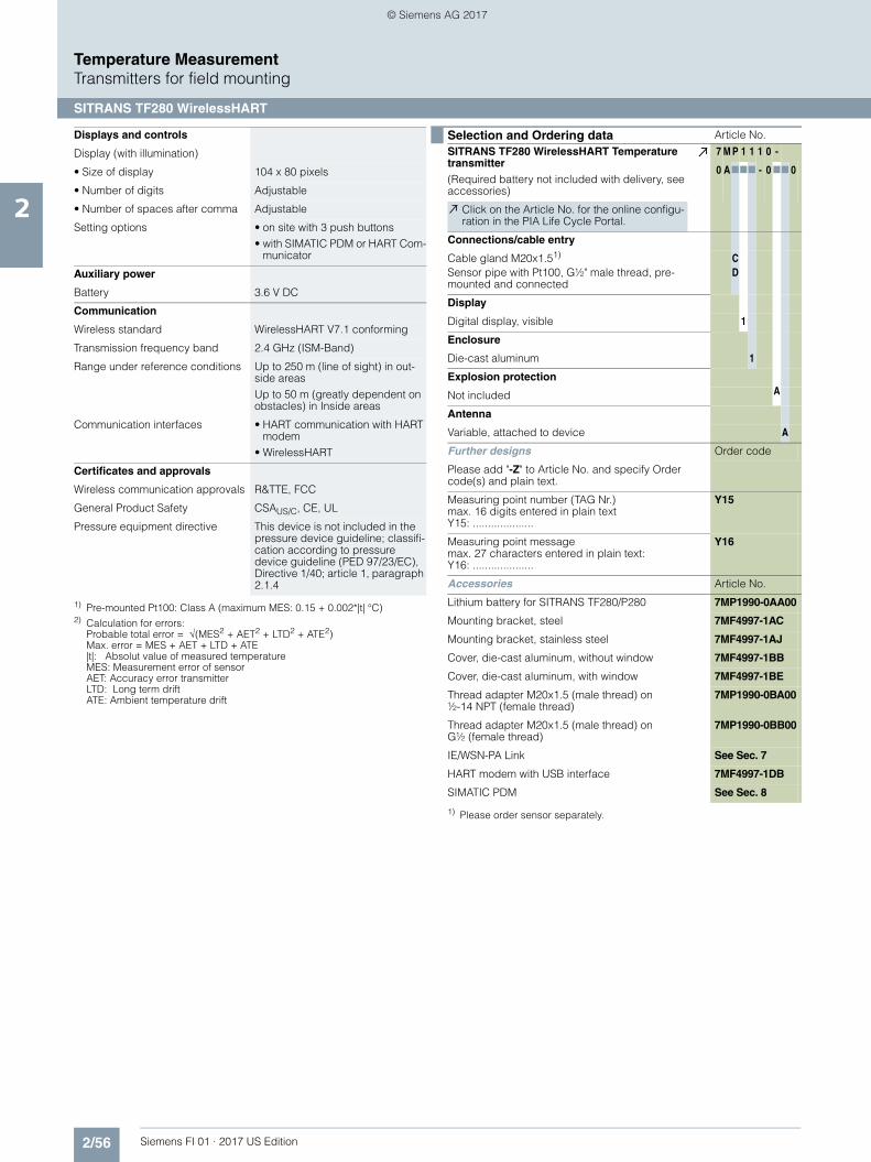
2/56 Siemens FI 01 · 2017 US Edition
Temperature MeasurementTransmitters for field mounting
SITRANS TF280 WirelessHART
2
Displays and controls
Display (with illumination)
• Size of display 104 x 80 pixels
• Number of digits Adjustable
• Number of spaces after comma Adjustable
Setting options • on site with 3 push buttons• with SIMATIC PDM or HART Com-
municator
Auxiliary power
Battery 3.6 V DC
Communication
Wireless standard WirelessHART V7.1 conforming
Transmission frequency band 2.4 GHz (ISM-Band)
Range under reference conditions Up to 250 m (line of sight) in out-side areasUp to 50 m (greatly dependent on obstacles) in Inside areas
Communication interfaces • HART communication with HARTmodem
• WirelessHART
Certificates and approvals
Wireless communication approvals R&TTE, FCC
General Product Safety CSAUS/C, CE, UL
Pressure equipment directive This device is not included in the pressure device guideline; classifi-cation according to pressure device guideline (PED 97/23/EC), Directive 1/40; article 1, paragraph 2.1.4
1) Pre-mounted Pt100: Class A (maximum MES: 0.15 + 0.002*|t| °C)2) Calculation for errors:
Probable total error = √(MES2 + AET2 + LTD2 + ATE2)Max. error = MES + AET + LTD + ATE|t|: Absolut value of measured temperatureMES: Measurement error of sensorAET: Accuracy error transmitterLTD: Long term driftATE: Ambient temperature drift
Selection and Ordering data Article No.
SITRANS TF280 WirelessHART Temperature transmitter(Required battery not included with delivery, see accessories)
7 M P 1 1 1 0 -
0 A777 - 0 77 0
Click on the Article No. for the online configu-ration in the PIA Life Cycle Portal.
Connections/cable entry
Cable gland M20x1.51)
1) Please order sensor separately.
CSensor pipe with Pt100, G½" male thread, pre-mounted and connected
D
Display
Digital display, visible 1
Enclosure
Die-cast aluminum 1
Explosion protection
Not included A
Antenna
Variable, attached to device A
Further designs Order code
Please add "-Z" to Article No. and specify Order code(s) and plain text.
Measuring point number (TAG Nr.)max. 16 digits entered in plain textY15: ....................
Y15
Measuring point messagemax. 27 characters entered in plain text: Y16: ....................
Y16
Accessories Article No.
Lithium battery for SITRANS TF280/P280 7MP1990-0AA00
Mounting bracket, steel 7MF4997-1AC
Mounting bracket, stainless steel 7MF4997-1AJ
Cover, die-cast aluminum, without window 7MF4997-1BB
Cover, die-cast aluminum, with window 7MF4997-1BE
Thread adapter M20x1.5 (male thread) on ½-14 NPT (female thread)
7MP1990-0BA00
Thread adapter M20x1.5 (male thread) on G½ (female thread)
7MP1990-0BB00
IE/WSN-PA Link See Sec. 7
HART modem with USB interface 7MF4997-1DB
SIMATIC PDM See Sec. 8
© Siemens AG 2017

2/57Siemens FI 01 · 2017 US Edition
Temperature MeasurementTransmitters for field mounting
SITRANS TF280 WirelessHART
2
■ Dimensional drawings
SITRANS TF280 WirelessHART temperature transmitter with Pt100, dimensions in mm (inch).Please see the dimensional drawing of the mounting bracket on page 1/196.
Antenna
Pt100
SW
2790°
130 (5.12)
112
(4.4
)
242
(9.5
)
52 (2
.05)
101 (3.98)Ø
8 (0
.32)
G½
B
14 (0.55)
352 (13.9)
154 (6.06)
Ø 8
0 (3
.15)
Ø 80 (3.15)
© Siemens AG 2017
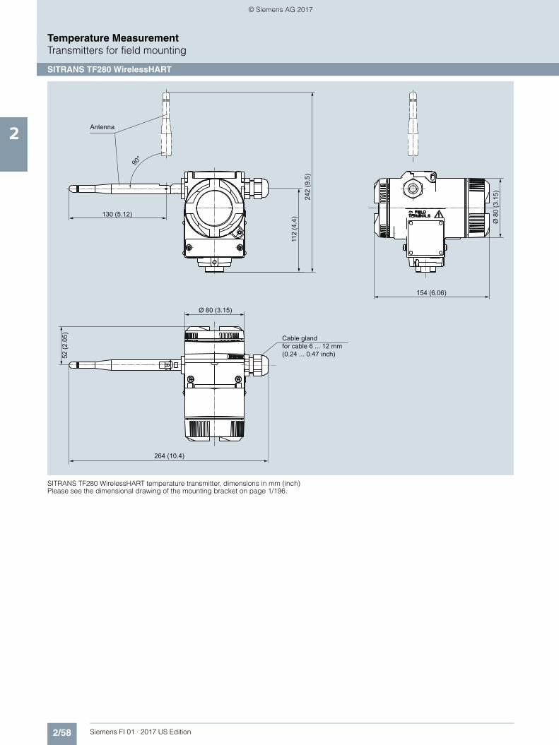
2/58 Siemens FI 01 · 2017 US Edition
Temperature MeasurementTransmitters for field mounting
SITRANS TF280 WirelessHART
2
SITRANS TF280 WirelessHART temperature transmitter, dimensions in mm (inch)Please see the dimensional drawing of the mounting bracket on page 1/196.
Cable glandfor cable 6 ... 12 mm(0.24 ... 0.47 inch)
Antenna
90°
130 (5.12)
112
(4.4
)
242
(9.5
)
52 (2
.05)
264 (10.4)
154 (6.06)
Ø 8
0 (3
.15)
Ø 80 (3.15)
© Siemens AG 2017

2/59Siemens FI 01 · 2017 US Edition
Temperature MeasurementTransmitter for field mounting/field indicator
SITRANS TF - Transmitter, two-wire system and SITRANS TF - Field indicator for 4 to 20 mA
2
■ Overview
Our field devices for heavy industrial use• HART, Universal• 4 to 20 mA, universal• Field indicator for 4 to 20 mA signals
The temperature transmitter SITRANS TF works where others feel uncomfortable.
■ Benefits
• Universal use- as transmitter for resistance thermometer, thermocouple ele-
ment, Ω or mV signal- as field indicator for any 4 to 20 mA signals
• Local sensing of measured values over digital display• Rugged two-chamber enclosure in die-cast aluminium or
stainless steel• Degree of protection IP67• Test terminals for direct read-out of the output signal without
breaking the current loop• Can be mounted elsewhere if the measuring point
- is hard to access,- is subject to high temperatures,- is subject to vibrations from the system,- or if you want to avoid long neck tubes and/or protective
tubes.• Can be mounted directly on American-design sensors• Wide range of approvals for use in potentially explosive atmo-
spheres. "Intrinsically safe, non-sparking and flameproof" type of protections, for Europe and USA.
• SIL2 (with Order Code C20), SIL2/3 (with C23)
■ Application
SITRANS TF can be used everywhere where temperatures need to be measured under particularly adverse conditions, or wherea convenient local display is ideal. Which is why users from allindustries have opted for this field device. The rugged enclosure protects the electronics. The stainless steel model is almostcompletely resistant to sea water and other aggressive ele-ments. The inner workings offer high measuring accuracy, uni-versal input and a wide range of diagnostic options.
■ Function
Configuration
The communication capability over the HART protocol V 5.9 ofthe SITRANS TF with an integrated SITRANS TH300 permits pa-rameterization using a PC or HART communicator (hand-heldcommunicator). The SIMATIC PDM makes it easy.
Parameterization is carried out using a PC for SITRANS TF withthe integrated and programmable SITRANS TK. Available forthis purpose are a special modem and the software toolSIPROM T.
Mode of operation
Mode of operation of SITRANS TF as temperature transmitter
The sensor signal, whether resistance thermometer, thermocou-ple element or Ω or mV signal, is amplified and linearized. Sen-sor and output side are electrically isolated. An internal coldjunction is integrated for measurements with thermocouple ele-ments.
The device outputs a temperature-linear direct current of 4 to20 mA. As well as the analog transmission of measured valuesfrom 4 to 20 mA, the HART version also supports digital commu-nication for online diagnostics, measured value transmissionand configuration.
SITRANS TF automatically detects when a sensor should be in-terrupted or is indicating a short-circuit. The practical test termi-nals allow direct measurement of 4 to 20 mA signals over an am-meter without interrupting the output current loop.
Mode of operation of SITRANS TF as field indicator
Any 4 to 20 mA signal can be applied to the generous terminalblock. As well as a range of predefined measurement units, theadjustable indicator also supports the input of customized units. This means that any 4 to 20 mA signal can be represented asany type of unit, e.g. pressure, flow rate, filling level or tempera-ture.
Mode of operation: SITRANS TF with integrated transmitter and digital display
1 Analog-to-digital converter
2 Electrical isolation
3 Microprocessor
4 Digital-to-analog converter
5 Power supply
6 PC/laptop
7 HART modem
8 Digital display (option)
9 Test connector
Sensor
Power supply
Load
000000°CTC RTD
AA
DDμP
SITRANS TF
SITRANS TH3001 3 42 5
67
89
© Siemens AG 2017

2/60 Siemens FI 01 · 2017 US Edition
Temperature MeasurementTransmitter for field mounting/field indicator
SITRANS TF - Transmitter, two-wire system and SITRANS TF - Field indicator for 4 to 20 mA
2
■ Technical specifications
Input
Resistance thermometer
Measured variable Temperature
Sensor type
• to IEC 60751 Pt25 … Pt1000
• to JIS C 1604; a=0.00392 K-1 Pt25 … Pt1000
• to IEC 60751 Ni25 … Ni1000
Units °C and °F
Connection
• Normal connection 1 resistance thermometer (RTD) in 2-wire, 3-wire or 4-wire system
• Generation of average value Series or parallel connection of several resistance thermometers in a two-wire system for the genera-tion of average temperatures or for adaptation to other device types
• Generation of difference 2 resistance thermometers (RTD) in 2-wire system (RTD 1 – RTD 2 or RTD 2 – RTD 1)
Interface
• Two-wire system Parameterizable line resistance ≤ 100 Ω (loop resistance)
• Three-wire system No balancing required
• Four-wire system No balancing required
Sensor current ≤ 0.45 mA
Response time ≤ 250 ms for 1 sensor with open-circuit monitoring
Open-circuit monitoring Always active (cannot be dis-abled)
Short-circuit monitoring can be switched on/off (default value: ON)
Measuring range parameterizable (see table "Digi-tal measuring errors")
Min. measured span 10 °C (18 °F)
Characteristic curve Temperature-linear or special characteristic
Resistance-based sensors
Measured variable Actual resistance
Sensor type Resistance-based, potentiome-ters
Units Ω
Connection
• Normal connection 1 resistance-based sensor (R) in 2-wire, 3-wire or 4-wire system
• Generation of average value 2 resistance-based sensors in 2-wire system for generation of average value
• Generation of difference 2 resistance-based sensor in 2-wire system (R 1 – R 2 or R 2 – R 1)
Interface
• Two-wire system Parameterizable line resistance ≤ 100 Ω (loop resistance)
• Three-wire system No balancing required
• Four-wire system No balancing required
Sensor current ≤ 0.45 mA
Response time ≤ 250 ms for 1 sensor with open-circuit monitoring
Open-circuit monitoring Can be switched off
Short-circuit monitoring Can be switched off (value is adjustable)
Measuring range parameterizable max. 0 ... 2200 Ω (see table "Digital measuring errors")
Min. measured span 5 ... 25 Ω (see Table "Digital mea-suring errors")
Characteristic curve Resistance-linear or special char-acteristic
Thermocouples
Measured variable Temperature
Sensor type (thermocouples)• Type B Pt30Rh-Pt6Rh to DIN IEC 584• Type C W5 %-Re acc. to ASTM 988• Type D W3 %-Re acc. to ASTM 988• Type E NiCr-CuNi to DIN IEC 584• Type J Fe-CuNi to DIN IEC 584• Type K NiCr-Ni to DIN IEC 584• Type L Fe-CuNi to DIN 43710• Type N NiCrSi-NiSi to DIN IEC 584• Type R Pt13Rh-Pt to DIN IEC 584• Type S Pt10Rh-Pt to DIN IEC 584• Type T Cu-CuNi to DIN IEC 584• Type U Cu-CuNi to DIN 43710
Units °C or °F
Connection
• Normal connection 1 thermocouple (TC)
• Generation of average value 2 thermocouples (TC)
• Generation of difference 2 thermocouples (TC) (TC 1 – TC 2 or TC 2 – TC 1)
Response time ≤ 250 ms for 1 sensor with open-circuit monitoring
Open-circuit monitoring Can be switched off
Cold junction compensation
• Internal With integrated Pt100 resistance thermometer
• External With external Pt100 IEC 60751 (2-wire or 3-wire connection)
• External fixed Cold junction temperature can be set as fixed value
Measuring range parameterizable (see table "Digi-tal measuring errors")
Min. measured span Min. 40 ... 100 °C (72 ... 180 °F) (see table "Digital measuring errors")
Characteristic curve Temperature-linear or special characteristic
mV sensor
Measured variable DC voltage
Sensor type DC voltage source (DC voltage source possible over an exter-nally connected resistor)
Units mV
Response time ≤ 250 ms for 1 sensor with open-circuit monitoring
Open-circuit monitoring Can be switched off
Measuring range -10 ... +70 mV-100 ... +1100 mV
Min. measured span 2 mV or 20 mV
Overload capability of the input -1.5 ... +3.5 V DC
Input resistance ≥ 1 MΩ
Characteristic curve Voltage-linear or special charac-teristic
© Siemens AG 2017

2/61Siemens FI 01 · 2017 US Edition
Temperature MeasurementTransmitter for field mounting/field indicator
SITRANS TF - Transmitter, two-wire system and SITRANS TF - Field indicator for 4 to 20 mA
2
Factory setting (transmitter): • Pt100 (IEC 751) with 3-wire circuit• Measuring range: 0 ... 100 °C (32 ... 212 °F)• Error signal in the event of sensor breakage: 22.8 mA• Sensor offset: 0 °C (0 °F)• Damping 0.0 s
Output
Output signal 4 ... 20 mA, 2-wire
Communication with SITRANS TH300
acc. to HART Rev. 5.9
Digital display
Digital display (optional) In current loop
Display Max. 5 digits
Digit height 9 mm (0.35 inch)
Display range -99 999 ... + 99 999
Units any (max. 5 char.)
Setting:Zero point, full-scale value and unit
with 3 buttons
Load voltage 2.1 V
Measuring accuracy
Digital measuring errors See table "Digital measuring errors"
Reference conditions
• Auxiliary power 24 V ± 1 %
• Load 500 Ω
• Ambient temperature 23 °C (73.4 °F)
• Warming-up time > 5 min
Error in the analog output (digi-tal/analog converter)
< 0.025 % of span
Error due to internal cold junction < 0.5 °C (0.9 °F)
Influence of ambient temperature
• Analog measuring error 0.02 % of span/10 °C (18 °F)
• Digital measuring errors
- with resistance thermometers 0.06 °C (0.11 °F)/10°C (18 °F)
- with thermocouples 0.6 °C (1.1 °F)/10°C (18 °F)
Auxiliary power effect < 0.001 % of span/V
Effect of load impedance < 0.002 % of span/100 Ω
Long-term drift
• In the first month < 0.02 % of span
• After one year < 0.3 % of span
• After 5 years < 0.4 % of span
Conditions of use
Ambient conditions
Storage temperature -40 ... +85 °C (-40 ... +185 °F)
Condensation Permissible
Electromagnetic compatibility According to EN 61326 and NAMUR NE21
Degree of protection to EN 60529 IP67
Construction
Weight Approx. 1.5 kg (3.3 lb) without options
Dimensions See "Dimensional drawings"
Enclosure material Die-cast aluminum, low in copper, GD-AlSi 12 or stainless steel, polyester-based lacquer, stain-less steel rating plate
Electrical connection, sensor con-nection
Screw terminals, cable inlet via M20 x 1.5 or ½-14 NPT screwed gland
Mounting bracket (optional) Steel, galvanized and chrome-plated or stainless steel
Auxiliary power
Without digital display 11 ... 35 V DC (30 V for Ex ib; 32 V for Ex ic and Ex nA)
With digital display 13.1 ... 5 V DC (30 V for Ex ib; 32 V for Ex ic and Ex nA)
Electrically isolated Between input and output
• Test voltage U eff = 1 kV, 50 Hz, 1 min
Certificates and approvals
Explosion protection ATEX
• "Intrinsic safety" type of protection with digital display:II 2 (1) G EEx ia IIC T4without digital display:II 2 (1) G EEx ia IIC T6
- EC type test certificate ZELM 11 ATEX 0471 X
• "Operating equipment that is non-ignitable and has limited energyfor zone 2" type of protection
II 3G EEx nAL IIC T6/T4
- EC type test certificate ZELM 11 ATEX 0471 X
• "Flame-proof enclosure" type ofprotection
II 2 G EEx d IIC T5/T6II 1D Ex tD A20 IP65 T100 °C, T85 °C
- EC type test certificate ZELM 11 ATEX 0472 X
Explosion protection to FM Certificate of Compliance 3017742
• Identification (XP, DIP, NI, S) • XP/I/1/BCD/T5 Ta = 85 °C(185 °F), T6 Ta = 50 °C (112 °F),Type 4X
• DIP/II, III/1/EFG/T5 Ta = 85 °C(185 °F), T6 Ta = 50 °C (112 °F),Type 4X
• NI/I/2/ABCD/T5 Ta = 85 °C(185 °F), T6 Ta = 50 °C (112 °F), Type 4X
• S/II, III/2/FG/T5 Ta = 85 °C(185 °F), T6 Ta = 50 °C (112 °F),Type 4X
Other certificates IECEx, GOST, INMETRO, NEPSI, KOSHA
Hardware and software require-ments
• For the parameterization softwareSIPROM T for SITRANS TF withTH200
- Personal computer PC with CD-ROM drive and USB
- PC operating system Windows 98, NT, 2000, XP, 7 and Win 8
• For the parameterization softwareSIMATIC PDM for SITRANS TH300
See chapter 8 "Software", "SIMATIC PDM"
Communication
Load for HART connection 230 ... 1100 Ω
• Two-core shielded ≤ 3.0 km (1.86 mi)
• Multi-core shielded ≤ 1.5 km (0.93 mi)
Protocol HART protocol, version 5.9
© Siemens AG 2017

2/62 Siemens FI 01 · 2017 US Edition
Temperature MeasurementTransmitter for field mounting/field indicator
SITRANS TF - Transmitter, two-wire system and SITRANS TF - Field indicator for 4 to 20 mA
2
Digital measuring errors
Resistance thermometer
Resistance-based sensors
Thermocouples
1) The digital accuracy in the range 0 to 300 °C (32 to 572 °F) is 3 °C (5.4 °F).2) The digital accuracy in the range 1750 to 2300 °C (3182 to 4172 °F) is 2 °C
(3.6 °F).
mV sensor
The digital accuracy is the accuracy after the analog/digital con-version including linearization and calculation of the measured value.
An additional error is generated in the output current 4 to 20 mA as a result of the digital/analog conversion of 0.025 % of the set span (digital-analog error).
The total error under reference conditions at the analog output is the sum from the digital error and the digital-analog error (poss. with the addition of cold junction errors in the case of thermocou-ple measurements).
Input Measuring range Min. mea-sured span
Digital accuracy
°C / (°F) °C) (°F) °C (°F)
to IEC 60751
Pt25 -200 ... +850(-328 ... +1562)
10 (18) 0.3 (0.54)
Pt50 -200 ... +850(-328 ... +1562)
10 (18) 0.15 (0.27)
Pt100 ... Pt200 -200 ... +850(-328 ... +1562)
10 (18) 0.1 (0.18)
Pt500 -200 ... +850(-328 ... +1562)
10 (18) 0.15 (0.27)
Pt1000 -200 ... +350(-328 ... +662)
10 (18) 0.15 (0.27)
to JIS C1604-81
Pt25 -200 ... +649(-328 ... +1200)
10 (18) 0.3 (0.54)
Pt50 -200 ... +649(-328 ... +1200)
10 (18) 0.15 (0.27)
Pt100 ... Pt200 -200 ... +649(-328 ... +1200)
10 (18) 0.1 (0.18)
Pt500 -200 ... +649(-328 ... +1200)
10 (18) 0.15 (0.27)
Pt1000 -200 ... +350(-328 ... +662)
10 (18) 0.15 (0.27)
Ni 25 to Ni1000 -60 ... +250(-76 ... +482)
10 (18) 0.1 (0.18)
Input Measuring range Min. mea-sured span
Digital accuracy
Ω Ω Ω
Resistance 0 ... 390 5 0.05
Resistance 0 ... 2200 25 0.25
Input Measuring range Min. mea-sured span
Digital accuracy
°C / (°F) °C (°F) °C (°F)
Type B 0 ... 1820(32 ... 3308)
100 (180) 21) (3.6)1)
Type C (W5) 0 ... 2300(32 ... 4172)
100 (180) 12) (1.8)2)
Type D (W3) 0 ... 2300(32 ... 4172)
100 (180) 12) (1.8)2)
Type E -200 ... +1000(-328 ... +1832)
50 (90) 1 (1.8)
Type J -210 ... +1200(-346 ... +2192)
50 (90) 1 (1.8)
Type K -200 ... +1370(-328 ... +2498)
50 (90) 1 (1.8)
Type L -200 ... +900(-328 ... +1652)
50 (90) 1 (1.8)
Type N -200 ... +1300(-328 ... +2372)
50 (90) 1 (1.8)
Type R -50 ... +1760(-58 ... +3200)
100 (180) 2 (3.6)
Type S -50 ... +1760(-58 ... +3200)
100 (180) 2 (3.6)
Type T -20 ... +400(-328 ... +752)
40 (72) 1 (1.8)
Type U -200 ... +600(-328 ... +1112)
50 (90) 2 (3.6)
Input Measuring span Min. mea-sured span
Digital accuracy
mV mV μV
mV sensor -10 ... +70 2 40
mV sensor -100 ... +1100 20 400
© Siemens AG 2017

2/63Siemens FI 01 · 2017 US Edition
Temperature MeasurementTransmitter for field mounting/field indicator
SITRANS TF - Transmitter, two-wire system and SITRANS TF - Field indicator for 4 to 20 mA
2
Selection and Ordering data Article No.
Temperature transmitter in field housingTwo-wire system 4 ... 20 mA, with electrical isolation, with documentation on MiniDVD
7 N G 3 1 3 7 - 77777
Click on the Article No. for the online confi-guration in the PIA Life Cycle Portal.
Integrated transmitterSITRANS TH200, programmable• Without Ex protection 5 0• With Ex ia 5 1• With Ex nAL for zone 2 5 2• Total device SITRANS TF Ex d1) 5 4• Total device SITRANS TF according to FM
(XP, DIP, NI, S)1)5 5
SITRANS TH300, communication capability according to HART V 5.9• Without Ex-protection 6 0• With Ex ia 6 1• With Ex nAL for zone 2 6 2• Total device SITRANS TF Ex d1) 6 4• Total device SITRANS TF according to FM
(XP, DIP, NI, S)1)6 5
EnclosureDie-cast aluminium AStainless steel precision casting E
Connections/cable inletScrewed glands M20x1.5 BScrewed glands ½-14 NPT C
Digital indicatorWithout 0With 1
Mounting bracket and securing partsWithout 0Made of steel 1Made of stainless steel 2
Further designs Order codePlease add "-Z" to Article No. and specify Order code(s) and plain text.
Test protocol (5 measuring points) C11Functional safety SIL2 C20Functional safety SIL2/3 C23Explosion protection• Explosion protection Ex ia to INMETRO
(Brazil) (only with 7NG313.-1....)E25
• Explosion protection Ex d to INMETRO(Brazil) (only with 7NG313.-4....)
E26
• Explosion protection Ex nA to INMETRO(Brazil) (only with 7NG313.-2...)
E27
• Explosion protection Ex i to NEPSI(China) (only with 7NG313.-1...)
E55
• Explosion protection Ex d to NEPSI(China) (only with 7NG313.-4....)
E56
• Explosion protection Ex nA to NEPSI(China) (only with 7NG313.-2...)
E57
• Explosion protection Ex d to KOSHA(Korea) (only with 7NG313.-4...)
E70
• Two coats of lacquer on casing and cover(PU on epoxy)
G10
• Transient protection J01• Cable gland CAPRI 1/2 NPT ADE 4F,
nickle-plated brass (CAPRI 848694 and810634) included
D57
• Cable gland 1/2 NPT ADE 1F,cable diam. 6 ... 12 (CAPRI 818694 and810534) included
D58
• Cable gland 1/2 NPT ADE 4F, stainless steel (CAPRI 848699 and 810634) included
D59
• Cable gland 1/2 NPT ADE 1F, cable diam. 4 ... 8.5 (CAPRI 818674 and 810534) included
D60
Selection and Ordering data Order Code
Customer-specific programmingAdd "-Z" to Article No. and specify Order code(s)
Measuring range to be setSpecify in plain text (max. 5 digits):Y01: ... to ... °C, °F
Y012)
Measuring point no. (TAG), max. 8 characters Y173)
Meas. point descriptor, max. 16 characters Y234)
Meas. point message, max. 32 characters Y244)
Only inscription on measuring point label: specify in plain text: Measuring range
Y224)
Pt100 (IEC) 2-wire, RL = 0 Ω U025)
Pt100 (IEC) 3-wire U035)
Pt100 (IEC) 4-wire U045)
Thermocouple type B U205)6)
Thermocouple type C (W5) U215)6)
Thermocouple type D (W3) U225)6)
Thermocouple type E U235)6)
Thermocouple type J U245)6)
Thermocouple type K U255)6)
Thermocouple type L U265)6)
Thermocouple type N U275)6)
Thermocouple type R U285)6)
Thermocouple type S U295)6)
Thermocouple type T U305)6)
Thermocouple type U U315)6)
With TC: CJC external (Pt100, 3-wire) U41
With TC: CJC external with fixed value, spe-cify in plain text
Y50
Special differing customer-specific program-ming, specify in plain text
Y097)
Fail-safe value 3.6 mA (instead of 22.8 mA) U363)
Supply units see Chapter "Supplementary Components".
1) Without cable gland.2) For customer-specific programming for RTD and TC, the start value and
the end value of the required measuring span must be specified here.3) For this selection, Y01 or Y09 must also be selected.4) If only Y22, Y23 or Y24 are ordered and the label only has to be on the tag
plate, Y01 does not have to be specified.5) For this selection, Y01 must also be selected.6) Internal cold junction compensation is selected as the default for TC.7) For customer-specific programming, for example mV and ohm, the start
value and the end value of the required measuring span and the unit must be entered here.
© Siemens AG 2017
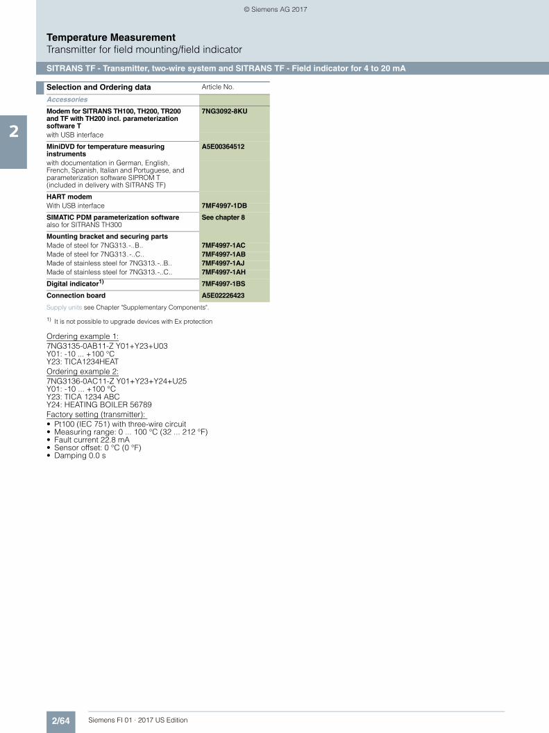
2/64 Siemens FI 01 · 2017 US Edition
Temperature MeasurementTransmitter for field mounting/field indicator
SITRANS TF - Transmitter, two-wire system and SITRANS TF - Field indicator for 4 to 20 mA
2
Ordering example 1:7NG3135-0AB11-Z Y01+Y23+U03Y01: -10 ... +100 °CY23: TICA1234HEATOrdering example 2:7NG3136-0AC11-Z Y01+Y23+Y24+U25Y01: -10 ... +100 °CY23: TICA 1234 ABCY24: HEATING BOILER 56789Factory setting (transmitter): • Pt100 (IEC 751) with three-wire circuit• Measuring range: 0 ... 100 °C (32 ... 212 °F)• Fault current 22.8 mA• Sensor offset: 0 °C (0 °F)• Damping 0.0 s
Selection and Ordering data Article No.
Accessories
Modem for SITRANS TH100, TH200, TR200 and TF with TH200 incl. parameterization software T
7NG3092-8KU
with USB interface
MiniDVD for temperature measuring instruments
A5E00364512
with documentation in German, English, French, Spanish, Italian and Portuguese, and parameterization software SIPROM T (included in delivery with SITRANS TF)
HART modemWith USB interface 7MF4997-1DB
SIMATIC PDM parameterization softwarealso for SITRANS TH300
See chapter 8
Mounting bracket and securing partsMade of steel for 7NG313.-..B.. 7MF4997-1ACMade of steel for 7NG313.-..C.. 7MF4997-1ABMade of stainless steel for 7NG313.-..B.. 7MF4997-1AJMade of stainless steel for 7NG313.-..C.. 7MF4997-1AH
Digital indicator1)
1) It is not possible to upgrade devices with Ex protection
7MF4997-1BS
Connection board A5E02226423
Supply units see Chapter "Supplementary Components".
© Siemens AG 2017

2/65Siemens FI 01 · 2017 US Edition
Temperature MeasurementTransmitter for field mounting/field indicator
SITRANS TF - Transmitter, two-wire system and SITRANS TF - Field indicator for 4 to 20 mA
2
Ordering example 1:
7NG3130-0AB10-Z Y01+Y23Y01: -5...100 °CY23: TICA1234HEAT
Ordering example 2:
7NG3130-0AC10-Z Y01+Y23+Y24Y01: 0 ... 20 BARY23: PICA 1234 ABCY29: HEATING BOILER 67890
Factory setting (field indicator):
4 ... 20 mA
Selection and Ordering data Article No.
SITRANS TF field indicatorfor 4 ... 20 mA signals, with documentation on MiniDVD
7 N G 3 1 3 0 - 77777
Click on the Article No. for the online confi-guration in the PIA Life Cycle Portal.
Without Ex-protection 0 1With Ex ia 1 1With Ex nAL for zone 2 2 1Total device SITRANS TF Ex d1) 4 1Total device SITRANS TF according to FM (XP, DIP, NI, S)1)
5 1
EnclosureDie-cast aluminium AStainless steel precision casting E
Connections/cable inletScrewed glands M20x1.5 BScrewed glands ½-14 NPT C
Digital indicatorWith 1
Mounting bracket and securing partsWithout 0Made of steel 1Made of stainless steel 2
Further designs Order codePlease add "-Z" to Article No. and specify Order code(s) and plain text.
Test protocol (5 measuring points) C11
Explosion protection
• Explosion protection Ex ia to INMETRO(Brazil) (only with 7NG313.-1....)
E25
• Explosion protection Ex d to INMETRO(Brazil) (only with 7NG313.-4....)
E26
• Explosion protection Ex nA to INMETRO(Brazil) (only with 7NG313.-2...)
E27
• Explosion protection Ex i to NEPSI(China) (only with 7NG313.-1...)
E55
• Explosion protection Ex d to NEPSI(China) (only with 7NG313.-4....)
E56
• Explosion protection Ex nA to NEPSI(China) (only with 7NG313.-2...)
E57
• Explosion protection Ex d to KOSHA(Korea) (only with 7NG313.-4...)
E70
• Two coats of lacquer on casing and cover(PU on epoxy)
G10
• Transient protection J01
• Cable gland CAPRI 1/2 NPT ADE 4F,nickle-plated brass (CAPRI 848694 and810634) included
D57
• Cable gland 1/2 NPT ADE 1F,cable diam. 6 ... 12 (CAPRI 818694 and810534) included
D58
• Cable gland 1/2 NPT ADE 4F, stainless steel (CAPRI 848699 and 810634) included
D59
• Cable gland 1/2 NPT ADE 1F,cable diam. 4 ... 8.5 (CAPRI 818674 and810534) included
D60
Selection and Ordering data Order Code
Customer-specific programmingAdd "-Z" to Article No. and specify Order code(s)
Measuring range to be setSpecify in plain text (max. 5 digits):Y01: ... to ... °C, °F
Y012)
Only inscription on TAG plate: specify in plain text: Measuring range
Y223)
Only inscription on TAG plate: Measuring point descriptor, max. 16 characters
Y233)
Only inscription on TAG plate: Measuring point message, max. 27 characters
Y243)
Special differing customer-specific program-ming, specify in plain text
Y094)
Supply units see Chapter "Supplementary Components".
1) Without cable gland.2) For customer-specific programming for RTD and TC, the start value and
the end value of the required measuring span must be specified here.3) If only Y22, Y23 or Y24 are ordered and the label only has to be on the tag
plate, Y01 does not have to be specified.4) For customer-specific programming, for example mV and ohm, the start
value and the end value of the required measuring span and the unit must be entered here.
Selection and Ordering data Article No.
Accessories
MiniDVD for temperature measuring instruments
A5E00364512
with documentation in German, English, French, Spanish, Italian and Portuguese, and parameterization software SIPROM T (included in delivery with SITRANS TF)
Mounting bracket and securing partsMade of steel for 7NG313.-..B.. 7MF4997-1ACMade of steel for 7NG313.-..C.. 7MF4997-1ABMade of stainless steel for 7NG313.-..B.. 7MF4997-1AJMade of stainless steel for 7NG313.-..C.. 7MF4997-1AH
Digital indicator1)
1) It is not possible to upgrade devices with Ex protection
7MF4997-1BS
Connection board A5E02226423
© Siemens AG 2017

2/66 Siemens FI 01 · 2017 US Edition
Temperature MeasurementTransmitter for field mounting/field indicator
SITRANS TF - Transmitter, two-wire system and SITRANS TF - Field indicator for 4 to 20 mA
2
■ Dimensional drawings
SITRANS TF, dimensions in mm (inches)
6 Protective cover (without function)
7 Mounting bracket (option) with clamp for securing to a vertical or horizontal pipe
8 Cover with window for digital display
a: max. 164 (6.46) (M20x1.5) max. 189 (7.44) (½-14 NPT)
b: max. 25 (0.98) (M20x1.5) max. 50 (1.97) (½-14 NPT)
*) Dimensions for stainless steel enclosure
1 Sensor connection (screwed gland M20x1.5 or ½-14 NPT)
2 Blanking plug
3 Electrical connection (screwed gland M20x1.5 or ½-14 NPT)
4 Terminal side, output signal
5 Terminal side, sensor
36.5
(1.4
4)
20 (0.7
9)50 (1.9
7)
52 (2.05)
144 (5.67)13 (0.51)
5 4
1
72 (2
.83)
123 (4.84)
68 (2
.68)
117
(4.6
1)
7
28(1.10)
55 (2.17)
8
Ø 50 ... 60(1.97 ... 2.36)
15* (0.59) 138* (5.43)
50* (1.97)
80 (3
.15)
80 (3.15)
237
(9.3
3)
3
26b
a
120
(4.7
2)
105 (4.13)
100* (3.94)
© Siemens AG 2017

2/67Siemens FI 01 · 2017 US Edition
Temperature MeasurementTransmitter for field mounting/field indicator
SITRANS TF - Transmitter, two-wire system and SITRANS TF - Field indicator for 4 to 20 mA
2
■ Schematics
SITRANS TF, sensor connection assignment
3 6
4 3-W 5
+ -3
4 5
6
3 6
4 3-W 5
+ -3
4 5
6
3 6
4 3-W 5
+ -3
4 5
6
3 6
4 3-W 5
+ -3
4 5
6
3 6
4 3-W 5
+ -3
4 5
6
3 6
4 3-W 5
+ -3
4 5
6
3 6
4 3-W 5
+ -3
4 5
6
3 6
4 3-W 5
+ -3
4 5
6
3 6
4 3-W 5
+ -3
4 5
6
3 6
4 3-W 5
+ -3
4 5
6
3 6
4 3-W 5
+ -3
4 5
6
3 6
4 3-W 5
+ -3
4 5
6
3 6
4 3-W 5
+ -3
4 5
6
3 6
4 3-W 5
+ -3
4 5
6
Resistance thermometer Resistance Thermocouple
Current measurementVoltage measurement
Two-wire system 1)
Three-wire system
Four-wire system
Generation of average value / difference 1)
Two-wire system 1)
Three-wire system
Four-wire system
Generation of average value / difference 1)
Cold junction compensationInternal/fixed value
Cold junction compensation with external Pt100 in two-wire system 1)
Cold junction compensation with external Pt100 in three-wire system
Generation of average value / difference with internal cold junction compensation
1) Programmable line resistance for the purpose of correction.
RTD
RTDRTD
R
R
R
R2
UR
I
+ -
+ -
R1
+ TC -
+ TC -
RTD
RTD2
RTD1
RTD+ TC -
+ TC1 - + TC2 -
© Siemens AG 2017

2/68 Siemens FI 01 · 2017 US Edition
Temperature MeasurementTransmitters for field mounting
SITRANS TF fieldbus transmitter
2
■ Overview
Our field devices for heavy industrial use• FOUNDATION fieldbus• PROFIBUS PAThe SITRANS TF temperature transmitter works where others can’t cope.
■ Benefits• For universal use as a transmitter for resistance thermometers,
thermocouple elements, Ω or mV signals• Rugged two-chamber enclosure in die-cast aluminium or
stainless steel• Degree of protection IP67• Can be mounted elsewhere if the measuring point
- is hard to access,- is subject to high temperatures,- is subject to vibrations from the system,- or if you want to avoid long neck tubes and/or protective
tubes.• Can be mounted directly on American-design sensors• Wide range of approvals for use in potentially explosive atmo-
spheres. "Intrinsically safe, non-sparking and flameproof" type of protection, for Europe and USA
■ Application
The SITRANS TF can be used everywhere where temperaturesneed to be measured under particularly harsh conditions. Which is why users from all industries have opted for this field device.
The rugged enclosure protects the electronics. The stainlesssteel model is almost completely resistant to sea water and other aggressive elements.
The inner workings offer high measuring accuracy, universal in-put and a wide range of diagnostic options.
■ Function
Features• Polarity-neutral bus connection• 24-bit analog-digital converter for high resolution• Electrically isolated• Version for use in hazardous areas• Special characteristic• Sensor redundance
Transmitter with PROFIBUS PA communication• Function blocks: 2 x analog
Transmitter with FOUNDATION fieldbus communication• Function blocks: 2 x analog and 1 x PID• Functionality: Basic or LAS
Mode of operation
The following function diagram explains the mode of operation of the transmitter.
The only difference between the two versions of the SITRANS TF (7NG3137-... and 7NG3138-...) is the type of field bus protocol used (PROFIBUS PA or FOUNDATION fieldbus).
SITRANS TF with TH400, function diagram
Optional inputs:
- Resistance thermometer
- Thermocouple- mV sensor
- Resistance-based sensors
Input 1
Input 2
TransformerInput 1Input 2DifferentialMean valueRedundancyTerminal temperatureEngineering units Diagnostic functionsTable linearizationPolynomial linearizationProcess calibration
A/D converter
Complex configurationCorrection coefficientFactory settings
- PROFIBUS PA protocol (7NG3137)or
- FOUNDATION Fieldbus protocol (7NG3138)
Bus connection
Ex
pow
er c
ircui
t
Electrically isolated
Internal Pt100
CommunicationCPU2
1
EEPROM
6
5
4
3
© Siemens AG 2017

2/69Siemens FI 01 · 2017 US Edition
Temperature MeasurementTransmitters for field mounting
SITRANS TF fieldbus transmitter
2
System communication
SITRANS TF with TH400, communication interface
■ Technical specifications
Input
Analog/digital conversion
• Measurement rate < 50 ms
• Resolution 24-bit
Resistance thermometer
Pt25 ... 1000 to IEC 60751/JIS C 1604
• Measuring range -200 ... +850 °C(-328 ... +1562 °F)
Ni25 ... 1000 to DIN 43760
• Measuring range -60 ... +250 °C (-76 ... +482 °F)
Cu10 ... 1000, α = 0.00427
• Measuring range -50 ... +200 °C (-58 ... +392 °F)
Line resistance per sensor cable Max. 50 Ω
Sensor current Nominal 0.2 mA
Sensor fault detection
• Sensor break detection Yes
• Sensor short-circuit detection Yes, < 15 Ω
Resistance-based sensors
Measuring range 0 ... 10 kΩ
Line resistance per sensor cable Max. 50 Ω
Sensor current Nominal 0.2 mA
Sensor fault detection
• Sensor break detection Yes
• Sensor short-circuit detection Yes, < 15 Ω
Thermocouple
to IEC 584 Measuring range
• Type B 400 ... 1820 °C (752 ... 3308 °F)
• Type E -100 ... +1000 °C(-148 ... +1832 °F)
• Type J -100 ... +1000 °C(-148 ... +1832 °F)
• Type K -100 ... +1200 °C(-148 ... +2192 °F)
• Type N -180 ... +1300 °C(-292 ... +2372 °F)
Bus terminator
Bus terminator
Segment coupler
Segment coupler
SITRANS TFwith TH400 PA
SITRANS TFwith TH400 FF
PROFIBUS PA
FOUNDATION Fieldbus
• Type R -50 ... +1760 °C (-58 ... +3200 °F)
• Type S -50 ... +1760 °C (-58 ... +3200 °F)
• Type T -200 ... +400 °C (-328 ... +752 °F)
to DIN 43710
• Type L -200 ... +900 °C(-328 ... +1652 °F)
• Type U -200 ... +600 °C(-328 ... +1112 °F)
to ASTM E988-90
• Type W3 0 ... 2300 °C (32 ... 4172 °F)
• Type W5 0 ... 2300 °C (32 ... 4172 °F)
External cold junction compensa-tion
-40 ... +135 °C (-40 ... +275 °F)
Sensor fault detection
• Sensor break detection Yes
• Sensor short-circuit detection Yes, < 3 mV
• Sensor current in the event ofopen-circuit monitoring
4 μA
mV sensor - voltage input
Measuring range -800 ... +800 mV
Input resistance 10 MΩ
Output
Filter time (programmable) 0 ... 60 s
Update time < 400 ms
Measuring accuracy
Accuracy is defined as the higher value of general values and basic values.
General values
Type of input Absolute accu-racy
Temperature coefficient
All ≤ ± 0.05 % of the measured value
≤ ± 0.002 % ofthe measuredvalue/°C
Basic values
Type of input Basic accuracy Temperature coefficient
Pt100 and Pt1000 ≤ ± 0.1 °C ≤ ± 0.002 °C/°C
Ni100 ≤ ± 0.15 °C ≤ ± 0.002 °C/°C
Cu10 ≤ ± 1.3 °C ≤ ± 0.02 °C/°C
Resistance-based sensors ≤ ± 0.05 Ω ≤ ± 0.002 Ω/°C
Voltage source ≤ ± 10 μV ≤ ± 0.2 μV/°C
Thermocouple, type:E, J, K, L, N, T, U
≤ ± 0.5 °C ≤ ± 0.01 °C/°C
Thermocouple, type:B, R, S, W3, W5
≤ ± 1 °C ≤ ± 0.025 °C/°C
Cold junction compensation ≤ ± 0.5 °C
Reference conditions
Warming-up time 30 s
Signal-to-noise ratio Min. 60 dB
Calibration condition 20 ... 28 °C (68 ... 82 °F)
© Siemens AG 2017

2/70 Siemens FI 01 · 2017 US Edition
Temperature MeasurementTransmitters for field mounting
SITRANS TF fieldbus transmitter
2
Conditions of use
Ambient conditions
Permissible ambient temperature -40 ... +85 °C (-40 ... +185 °F)
Permissible storage temperature -40 ... +85 °C (-40 ... +185 °F)
Relative humidity ≤ 98 %, with condensation
Insulation resistance
• Test voltage 500 V AC for 60 s
• Continuous operation 50 V AC/75 V DC
Electromagnetic compatibility
NAMUR NE21
EMC 2004/108/EC Emission and Noise Immunity
EN 61326-1, EN 61326-2-5
Construction
Weight Approx. 1.5 kg (3.3 lb) without options
Dimensions See "Dimensional drawings"
Enclosure materials • Die-cast aluminum, low in cop-per, GD-AlSi 12 or stainless steel
• Polyester-based lacquer for GDAlSi 12 enclosure
• Stainless steel rating plate
Electrical connection, sensor con-nection
• screw terminals• Cable inlet via M20 x 1.5 or ½
-14 NPT screwed gland• Bus connection with M12 plug
(optional)
Mounting bracket (optional) Steel, galvanized and chrome-plated or stainless steel
Degree of protection IP67 to EN 60529
Auxiliary power
Power supply
• Standard, Ex "d", Ex "nA", Ex "nL",XP, NI
10.0 ... 32 V DC
• Ex "ia", Ex "ib" 10.0 ... 30 V DC
• In FISCO/FNICO installations 10.0 ... 17.5 V DC
Power consumption < 11 mA
Max. increase in power consump-tion in the event of a fault
< 7 mA
Certificates and approvals
Explosion protection ATEX
EC type test certificate ZELM 11 ATEX 0471 X
• Type of protection "intrinsic safety i"(version: 7NG313x-1xxxx)
II 2(1) G Ex ia IIC T4/T6
Conformity statement ZELM 11 ATEX 0471 X
• "Operating equipment that is non-ignitable and has limited energy"type of protection(version: 7NG313x-2xxxx)
II 3 G Ex nA [nL] IIC T4/T6II 3 G Ex nL IIC T4/T6
EC type test certificate ZELM 11 ATEX 0472 X
• "Flame-proof enclosure" type ofprotection (version: 7NG313x-4xxxx)
II 2 G Ex d IIC T5/T6II 1D Ex tD A20 IP65 T100 °C, T85 °C
Explosion protection: FM for USA
• FM approval FM 3017742
• Type of protection XP, DIP, NI and S(version 7NG313x-5xxxx)
• XP / I / 1 / BCD / T5,T6; Type 4X• DIP / II, III / 1 / EFG / T5,T6; Type
4X• NI / I / 2 / ABCD / T5,T6; Type 4X• S / II, III / 2 / FG T5,T6; Type 4X
Other certificates GOST, INMETRO, NEPSI, KOSHA
Communication
Parameterization interface
• PROFIBUS PA connection
- Protocol A&D profile, Version 3.0
- Protocol EN 50170 Volume 2
- Address (for delivery) 126
- Function blocks 2 x analog
• FOUNDATION fieldbus connec-tion
- Protocol FF protocol
- Protocol FF design specifications
- Functionality Basic or LAS
- Version ITK 4.6
- Function blocks 2 x analog and 1 x PID
Factory setting
for SITRANS TH400 PA
Sensor Pt100 (IEC)
Type of connection 3-wire circuit
Unit °C
Failure mode Last valid value
Filter time 0 s
PA address 126
PROFIBUS Ident No. Manufacturer-specific
for SITRANS TH400 FF
Sensor Pt100 (IEC)
Type of connection 3-wire circuit
Unit °C
Failure mode Last valid value
Filter time 0 s
Node address 22
© Siemens AG 2017

2/71Siemens FI 01 · 2017 US Edition
Temperature MeasurementTransmitters for field mounting
SITRANS TF fieldbus transmitter
2
1) Without cable gland2) Not available for explosion protection Ex d or XP.3) For customer-specific programming for RTD and TC, the start value and
the end value of the required measuring span must be specified here.4) If only Y15, Y23 or Y25 are ordered and the label only has to be on the tag
plate, Y01 does not have to be specified.5) For this selection, Y01 or Y09 must also be selected.6) For this selection, Y01 must also be selected.7) Internal cold junction compensation is selected as the default for TC.8) For customer-specific programming, for example mV and ohm, the start
value and the end value of the required measuring span and the unit must be entered here.
Selection and Ordering data Article No.
Temperature transmitter in field enclosurewith fieldbus communication and electrical isolation, with documentation on MiniDVD
7 N G 3 1 3 7 - 777 0 7
Click on the Article No. for the online confi-guration in the PIA Life Cycle Portal.
Integrated transmitterSITRANS TH400 with PROFIBUS PA• Without Ex protection 7 0• With Ex ia (ATEX) 7 1• With Ex nAL for zone 2 (ATEX) 7 2• Total device SITRANS TF Ex d1) 7 4• Total device SITRANS TF according to FM
(XP, DIP, NI, S)1)7 5
SITRANS TH400, with FOUNDATION fieldbus• Without Ex protection 8 0• With Ex ia (ATEX) 8 1• With Ex nAL for zone 2 (ATEX) 8 2• Total device SITRANS TF Ex d1) 8 4• Total device SITRANS TF according to FM
(XP, DIP, NI, S)1)8 5
EnclosureDie-cast aluminium AStainless steel precision casting E
Connections/cable inletScrewed glands M20x1.5 BScrewed gland s ½-14 NPT C
Mounting bracket and fastening partsNone 0Made of steel 1Stainless steel 2
Further designs Order codePlease add "-Z" to Article No. and specify Order code(s) and plain text.
Test report (5 measuring points) C11
Bus connection
• M12 plug (metal), without mating connector M002)
• M12 plug (metal), with mating connector M012)
Explosion protection
• Explosion protection Ex ia to INMETRO(Brazil) (only with 7NG313.-1....)
E25
• Explosion protection Ex d to INMETRO(Brazil) (only with 7NG313.-4....)
E26
• Explosion protection Ex nA to INMETRO(Brazil) (only with 7NG313.-2...)
E27
• Explosion protection Ex i to NEPSI(China) (only with 7NG313.-1...)
E55
• Explosion protection Ex d to NEPSI(China) (only with 7NG313.-4....)
E56
• Explosion protection Ex nA to NEPSI(China) (only with 7NG313.-2...)
E57
• Explosion protection Ex d to KOSHA(Korea) (only with 7NG313.-4...)
E70
• Two coats of lacquer on casing and cover(PU on epoxy)
G10
• Transient protection J01
• Cable gland CAPRI 1/2 NPT ADE 4F,nickle-plated brass (CAPRI 848694 and810634) included
D57
• Cable gland 1/2 NPT ADE 1F,cable diam. 6 ... 12 (CAPRI 818694 and810534) included
D58
• Cable gland 1/2 NPT ADE 4F, stainless steel (CAPRI 848699 and 810634) included
D59
• Cable gland 1/2 NPT ADE 1F,cable diam. 4 ... 8.5 (CAPRI 818674 and810534) included
D60
Selection and Ordering data Order Code.
Customer-specific programmingAdd "-Z" to Article No. and specify Order code(s)
Measuring range to be setSpecify in plain text (max. 5 digits):Y01: ... to ... °C, °F
Y013)
Meas. point no. (TAG), max. 32 characters Y154)
Meas. point descriptor, max. 32 characters Y234)
Meas. point message, max. 32 characters Y245)
Bus address, specify in plain text Y254)
Pt100 (IEC) 2-wire, RL = 0 Ω U026)
Pt100 (IEC) 3-wire U036)
Pt100 (IEC) 4-wire U046)
Thermocouple type B U206)7)
Thermocouple type C (W5) U216)7)
Thermocouple type D (W3) U226)7)
Thermocouple type E U236)7)
Thermocouple type J U246)7)
Thermocouple type K U256)7)
Thermocouple type L U266)7)
Thermocouple type N U276)7)
Thermocouple type R U286)7)
Thermocouple type S U296)7)
Thermocouple type T U306)7)
Thermocouple type U U316)7)
With TC: CJC: external (Pt100, 3-wire) U41
With TC: CJC: external with fixed value, spe-cify in plain text
Y50
Special differing customer-specific program-ming, specify in plain text
Y098)
© Siemens AG 2017
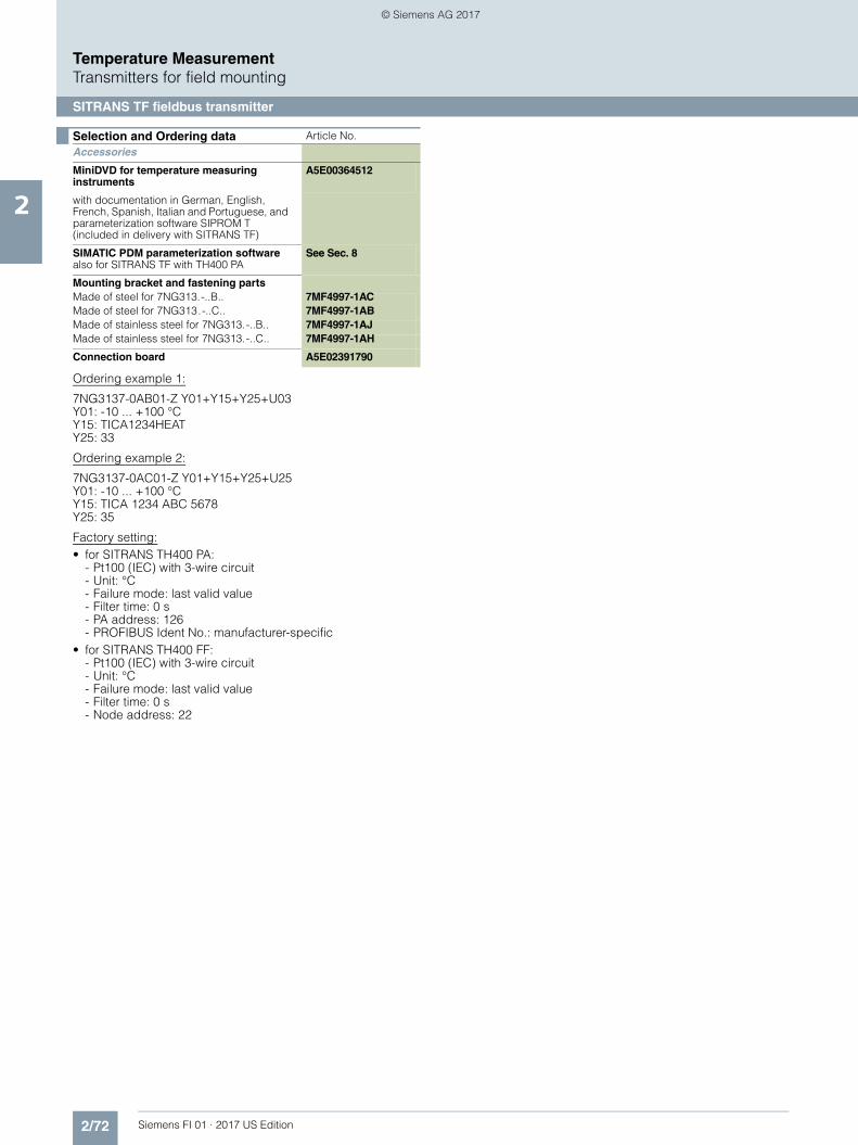
2/72 Siemens FI 01 · 2017 US Edition
Temperature MeasurementTransmitters for field mounting
SITRANS TF fieldbus transmitter
2
Ordering example 1:
7NG3137-0AB01-Z Y01+Y15+Y25+U03Y01: -10 ... +100 °CY15: TICA1234HEATY25: 33
Ordering example 2:
7NG3137-0AC01-Z Y01+Y15+Y25+U25Y01: -10 ... +100 °CY15: TICA 1234 ABC 5678Y25: 35
Factory setting:• for SITRANS TH400 PA:
- Pt100 (IEC) with 3-wire circuit- Unit: °C- Failure mode: last valid value- Filter time: 0 s- PA address: 126- PROFIBUS Ident No.: manufacturer-specific
• for SITRANS TH400 FF:- Pt100 (IEC) with 3-wire circuit- Unit: °C- Failure mode: last valid value- Filter time: 0 s- Node address: 22
Selection and Ordering data Article No.
Accessories
MiniDVD for temperature measuring instruments
A5E00364512
with documentation in German, English, French, Spanish, Italian and Portuguese, and parameterization software SIPROM T (included in delivery with SITRANS TF)
SIMATIC PDM parameterization softwarealso for SITRANS TF with TH400 PA
See Sec. 8
Mounting bracket and fastening partsMade of steel for 7NG313.-..B.. 7MF4997-1ACMade of steel for 7NG313.-..C.. 7MF4997-1ABMade of stainless steel for 7NG313.-..B.. 7MF4997-1AJMade of stainless steel for 7NG313.-..C.. 7MF4997-1AH
Connection board A5E02391790
© Siemens AG 2017
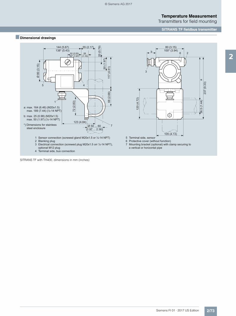
2/73Siemens FI 01 · 2017 US Edition
Temperature MeasurementTransmitters for field mounting
SITRANS TF fieldbus transmitter
2
■ Dimensional drawings
SITRANS TF with TH400, dimensions in mm (inches)
1 Sensor connection (screwed gland M20x1.5 or ½-14 NPT)2 Blanking plug3 Electrical connection (screwed plug M20x1.5 orr ½-14 NPT),
optional M12 plug4 Terminal side, bus connection
5 Terminal side, sensor6 Protective cover (without function)7 Mounting bracket (optional) with clamp securing to
a vertical or horizontal pipe
36.5
(1.4
4)
a: max. 164 (6.46) (M20x1.5) max. 189 (7.44) (½-14 NPT)
b: max. 25 (0.98) (M20x1.5) max. 50 (1.97) (½-14 NPT)
*) Dimensions for stainless steel enclosure
144 (5.67)138* (5.43)
80 (3.15)100* (3.94)
52 (2.05)50* (1.97)
55 (2.17)
123 (4.84)
105 (4.13)
Ø 8
0 (3
.15)
Ø 50 ... 60(1.97 ... 2.36)
72 (2
.83) 68
(2.6
8)
120
(4.7
2)
237
(9.3
3)a11
7 (4
.61)50
(1.9
7)
20 (0
.79)
28 (1.10)
b
1
5 4
2
3
7
6
© Siemens AG 2017

2/74 Siemens FI 01 · 2017 US Edition
Temperature MeasurementTransmitters for field mounting
SITRANS TF fieldbus transmitter
2
■ Schematics
SITRANS TF with TH400, sensor connection assignment
Resistance thermometer ResistanceThermocouple
Voltage measurement
Two-wire system 1)
Three-wire system
Four-wire system
Two-wire system 1)
Three-wire system
Four-wire system
Internal cold junction compensation
Cold junction compensation with external Pt100 in two-wire system 1)
Cold junction compensation with external Pt100 in three-wire system
1) Programmable line resistance for the purpose of correction.
Mean-value/differential or redundancy generation
1 sensor in two-wire system 1)
1 sensor in three-wire system
Mean-value/differential or redundancy generation2 x two-wire system 1)
Mean value, differential or redundancy generation with internal
cold junction compensation
Mean value, differential or redundancy generation and cold junction compensation
with internal Pt100 in two-wire system 1)
Mean value, differential or redundancy generation1 resistor in two-wire system 1)
1 resistor in three-wire system
Measurement of mean value, differential and redundancy with 2 voltage sources
One voltage source
12
12
+ -
+ -
+ -
12
+ -
12
+ - + -
21+ -
+ -
12
+ -+ -
© Siemens AG 2017

2/75Siemens FI 01 · 2017 US Edition
Temperature MeasurementMultipoint temperature transmitter
SITRANS TO500
2
■ Overview
SITRANS TO500 is a multipoint temperature transmitter for mea-suring temperatures and temperature profiles using fiber optic multipoint temperature measurement lances.
■ Benefits
• Evaluation of a large number of sensors (fiber Bragg grating(FBG)) in one temperature transmitter
• Low space requirement of the measurement lances• 4 measuring lance channels per transmitter• Easy to install• PROFIBUS DP - Simple integration into control system• Fast response to temperature changes• Exact, no recalibration required due to internal reference• Also suitable for high process temperatures
■ Application
The SITRANS TO500 is used for evaluating a large number ofsensors arranged on a fiber optic multipoint temperature measu-rement lance.
Up to 4 measurement lances with up to 48 sensors (fiber Bragggrating (FBG)) each can be processed simultaneously by aSITRANS TO500.
Accurate and fast determination of temperature profiles enables process optimization in terms of service life, quality and output.
Locations of excessive temperature rise are quickly and accura-tely detected, thereby preventing damage to the process, equip-ment and environment.
Wherever temperature profiles must be determined and installa-tion space is limited, the SITRANS TO500 with fiber-optic tempe-rature measurement is the right choice.
■ Design
The SITRANS TO500 multipoint temperature transmitter is loca-ted in the control cabinet in a compact aluminum enclosure formounting onto DIN rails.
The connectors are easy to access on the front:• 4 x connector for measurement lances• 1 x connector for power supply• 1 x connector PROFIBUS DP• 1 x connector Ethernet
The status displays are also located on the front.
■ Mode of operation
In the SITRANS TO500 multipoint temperature transmitter, light is generated in the wavelength of 1500 to 1600 nm and output tothe measurement lance by means of a continuously tunable la-ser light. Fiber Bragg gratings (FBG) are mounted at definedmeasurement points on the measurement lances. Each FBG re-flects light of a defined wavelength. The wavelength reflected by the FBGs varies as a function of temperature. The reflection atthe FBG is thus a measure of the temperature at the respectivemeasurement point. Up to 48 FBGs gratings per channel can be evaluated, depending on the temperature range.
A gas cell with fixed absorption line serves as a reference in theSITRANS TO500 and the wavelength determination is conti-nuously adjusted by it.
■ Function
The SITRANS TO500 has 4 channels which are evaluated simul-taneously. The wavelength reflected at each sensor in the multi-point temperature measurement lance depends on the tempera-ture, and this wavelength is output in the multipoint temperaturetransmitter. The temperature can be determined and displayedaccurately at up to 48 sensors per channel. The positions of thesensors can be specified by the customer. This leads to a flexi-ble and application-specific solution for the customer.
The measured temperatures are transferred to the control sys-tem via PROFIBUS DP. The parameters of the SITRANS TO500are set via the integrated Ethernet interface.
© Siemens AG 2017

2/76 Siemens FI 01 · 2017 US Edition
Temperature MeasurementMultipoint temperature transmitter
SITRANS TO500
2
■ Technical specifications
■ Selection and Ordering data Article-No.
Input
Channels 4
Measured variable Temperature
Input type Max. 48 sensors (FBGs) per channel
Characteristics Temperature-linear
Resolution 0.1 K
Measuring accuracy < 0.5 K
Repeatability < 0.5 K
Measuring cycle < 1 s
Measuring range -180 ... +800 °C(-292 ... +1472 °F) depending on the measurement lance
Unit °C
Power supply 24 V DC + 20 %
Power consumption Max. 15 W
Protection Against reverse polarity
Measuring velocity
• Measurement rate 1 Hz independent of the number of FBGs
Output
Output signal PROFIBUS DP
Optical power ≤ 1 mW per channel
Laser protection class Class 1
Rated conditions
Ambient conditions
Ambient temperature 0 ... 50 °C (32 ... 122 °F)
Storage temperature -40 ... +85 °C (-40 ... +185 °F)
Relative humidity < 80%, non condensing at 50 °C (122 °F)
Electromagnetic compatibility According to EN 61326 and NAMUR NE21
Degree of protection to EN 60529
Enclosure IP20
Design
Weight 2.4 kg (5.3 lb)
Dimensions See "Dimensional drawings"
DIN rail adapter Rear-mounted
Material Aluminum
Displays and control elements
LEDs "Power-on" (continuous light)"Status" (flashing during startup; otherwise continuous light)
Pushbutton "Reset" (system restart or address reset)
SITRANS TO500 multipoint temperature transmitter
7NG9551-4AA00-0AA0
Communication: PROFIBUS DPChannels: 4Power supply: 24 V DCOptical connection: FC/APC plugEnclosure: Aluminum, IP20
© Siemens AG 2017
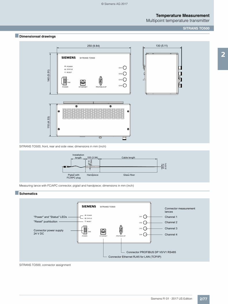
2/77Siemens FI 01 · 2017 US Edition
Temperature MeasurementMultipoint temperature transmitter
SITRANS TO500
2
■ Dimensionsal drawings
SITRANS TO500, front, rear and side view; dimensions in mm (inch)
Measuring lance with FC/APC connector, pigtail and handpiece; dimensions in mm (inch)
■ Schematics
SITRANS TO500, connector assignment
130 (5.11)250 (9.84)14
0 (5
.51)
110
(4.3
3)
-GND
+
POWER
SITRANS TO500
CH1
CH2
CH3
CH4
STATUS
RESET
POWER ETHERNET PROFIBUS DP
s
Pigtail withFC/APC plug
Handpiece Glass fiber
Cable lengthInstallation
length
Ø 0
.8(0
.031
)Ø 1
0(0
.394
)
100 (3.94)
Connector measurementlances
Channel 1
Channel 2
Channel 3
Channel 4
Connector PROFIBUS DP V0/V1 RS485
Connector Ethernet RJ45 for LAN (TCP/IP)
Connector power supply24 V DC
"Power" and "Status" LEDs
"Reset" pushbutton
POWER
STATUS
POWER PROFIBUS DPETHERNET
CH1
CH2
CH3
CH4
GND
+
RESET
-
SITRANS TO500s
© Siemens AG 2017
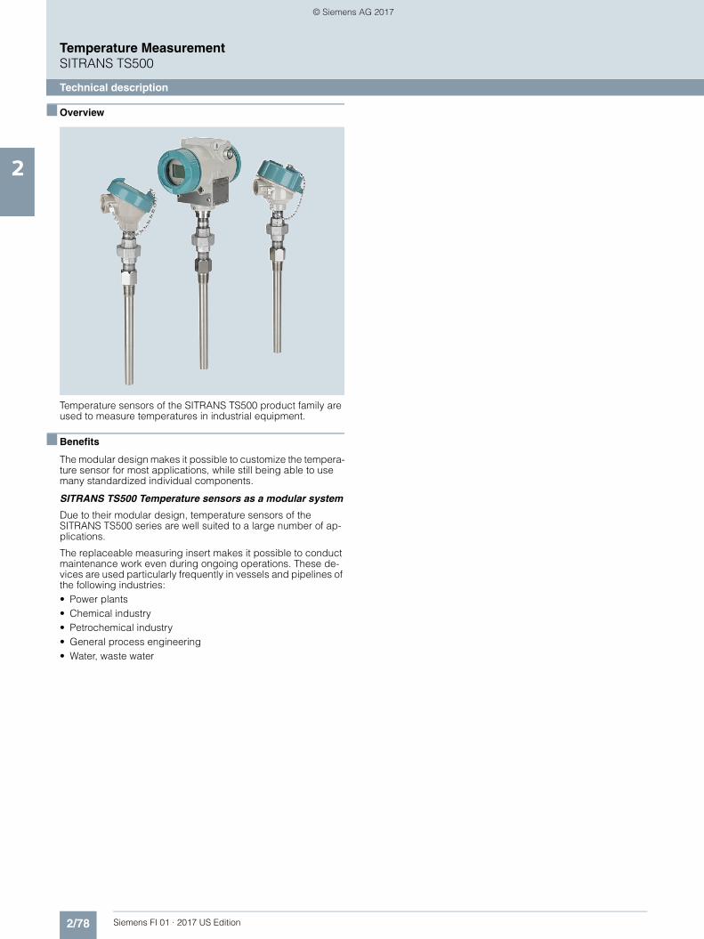
2/78 Siemens FI 01 · 2017 US Edition
Temperature MeasurementSITRANS TS500
Technical description
2
■ Overview
Temperature sensors of the SITRANS TS500 product family are used to measure temperatures in industrial equipment.
■ Benefits
The modular design makes it possible to customize the tempera-ture sensor for most applications, while still being able to usemany standardized individual components.
SITRANS TS500 Temperature sensors as a modular system
Due to their modular design, temperature sensors of theSITRANS TS500 series are well suited to a large number of ap-plications.
The replaceable measuring insert makes it possible to conductmaintenance work even during ongoing operations. These de-vices are used particularly frequently in vessels and pipelines of the following industries:• Power plants• Chemical industry• Petrochemical industry• General process engineering• Water, waste water
© Siemens AG 2017
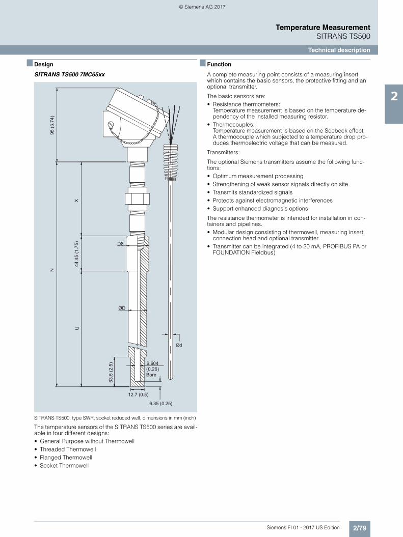
2/79Siemens FI 01 · 2017 US Edition
Temperature MeasurementSITRANS TS500
Technical description
2
■ Design
SITRANS TS500 7MC65xx
SITRANS TS500, type SWR, socket reduced well, dimensions in mm (inch)
The temperature sensors of the SITRANS TS500 series are avail-able in four different designs:• General Purpose without Thermowell• Threaded Thermowell• Flanged Thermowell• Socket Thermowell
■ Function
A complete measuring point consists of a measuring insert which contains the basic sensors, the protective fitting and an optional transmitter.
The basic sensors are:• Resistance thermometers:
Temperature measurement is based on the temperature de-pendency of the installed measuring resistor.
• Thermocouples:Temperature measurement is based on the Seebeck effect. A thermocouple which subjected to a temperature drop pro-duces thermoelectric voltage that can be measured.
Transmitters:
The optional Siemens transmitters assume the following func-tions:• Optimum measurement processing• Strengthening of weak sensor signals directly on site• Transmits standardized signals• Protects against electromagnetic interferences• Support enhanced diagnosis options
The resistance thermometer is intended for installation in con-tainers and pipelines.• Modular design consisting of thermowell, measuring insert,
connection head and optional transmitter.• Transmitter can be integrated (4 to 20 mA, PROFIBUS PA or
FOUNDATION Fieldbus)
Ød
D8
ØD
6.35 (0.25)
12.7 (0.5)
95 (3
.74)
N
44.4
5 (1
.75)
XU
6.604 (0.26) Bore
63.5
(2.5
)
© Siemens AG 2017
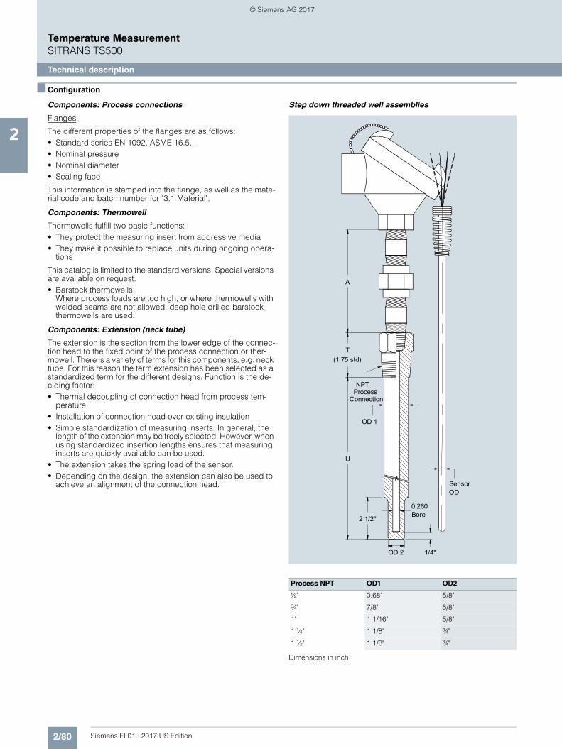
2/80 Siemens FI 01 · 2017 US Edition
Temperature MeasurementSITRANS TS500
Technical description
2
■ Configuration
Components: Process connections
Flanges
The different properties of the flanges are as follows:• Standard series EN 1092, ASME 16.5,..• Nominal pressure• Nominal diameter• Sealing face
This information is stamped into the flange, as well as the mate-rial code and batch number for "3.1 Material".
Components: Thermowell
Thermowells fulfill two basic functions:• They protect the measuring insert from aggressive media• They make it possible to replace units during ongoing opera-
tions
This catalog is limited to the standard versions. Special versions are available on request. • Barstock thermowells
Where process loads are too high, or where thermowells with welded seams are not allowed, deep hole drilled barstock thermowells are used.
Components: Extension (neck tube)
The extension is the section from the lower edge of the connec-tion head to the fixed point of the process connection or ther-mowell. There is a variety of terms for this components, e.g. neck tube. For this reason the term extension has been selected as a standardized term for the different designs. Function is the de-ciding factor:• Thermal decoupling of connection head from process tem-
perature• Installation of connection head over existing insulation• Simple standardization of measuring inserts: In general, the
length of the extension may be freely selected. However, when using standardized insertion lengths ensures that measuring inserts are quickly available can be used.
• The extension takes the spring load of the sensor.• Depending on the design, the extension can also be used to
achieve an alignment of the connection head.
Step down threaded well assemblies
Dimensions in inch
Process NPT OD1 OD2
½" 0.68" 5/8"
¾" 7/8" 5/8"
1" 1 1/16" 5/8"
1 ¼" 1 1/8" ¾"
1 ½" 1 1/8" ¾"
A
Sensor
ProcessConnection
0.260Bore
(1.75 std)
2 1/2"
1/4"
OD
U
OD 2
T
NPT
OD 1
© Siemens AG 2017

2/81Siemens FI 01 · 2017 US Edition
Temperature MeasurementSITRANS TS500
Technical description
2
Straight threaded well assemblies
Dimensions in inch
Tapered threaded well assemblies
Dimensions in inch
Process NPT OD1
½" 0.68"
¾" ¾"
1" 7/8"
1 ¼" 1 1/8"
1 ½" 1 1/8"
0.260Bore
1/4"
(1.75 std)
NPT ProcessConnection
Sensor OD
OD 1
A
U
T
Process NPT OD1 OD2
½" 0.68" 5/8"
¾" 7/8" 5/8"
1" 1 1/16" 5/8"
1 ¼" 1 1/8" ¾"
1 ½" 1 1/8" ¾"
Sensor
0.260Bore
1/4"
(1.75 std)
NPT ProcessConnection
A
OD
U
OD 2
T
OD 1
© Siemens AG 2017
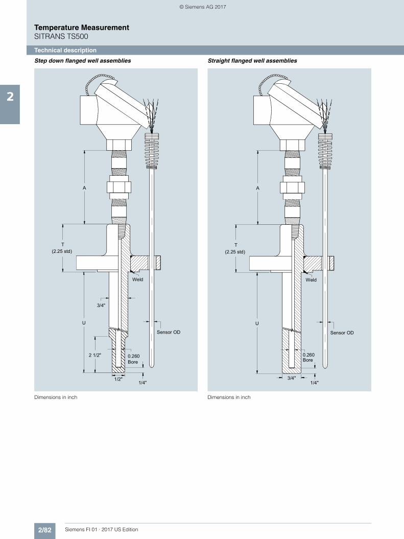
2/82 Siemens FI 01 · 2017 US Edition
Temperature MeasurementSITRANS TS500
Technical description
2
Step down flanged well assemblies
Dimensions in inch
Straight flanged well assemblies
Dimensions in inch
(2.25 std)
Weld
3/4"
0.260Bore
Sensor OD
2 1/2"
T
A
U
1/4"1/2"
(2.25 std)
Weld
0.260Bore
Sensor OD
T
A
U
1/4"3/4"
© Siemens AG 2017
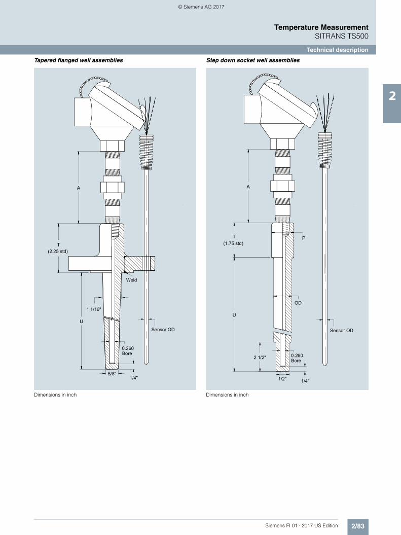
2/83Siemens FI 01 · 2017 US Edition
Temperature MeasurementSITRANS TS500
Technical description
2
Tapered flanged well assemblies
Dimensions in inch
Step down socket well assemblies
Dimensions in inch
(2.25 std)
Weld
0.260Bore
Sensor OD
T
A
U
5/8"1/4"
1 1/16"
Sensor OD
(1.75 std)
0.260Bore
T
U
OD
2 1/2"
1/4"1/2"
P
A
© Siemens AG 2017
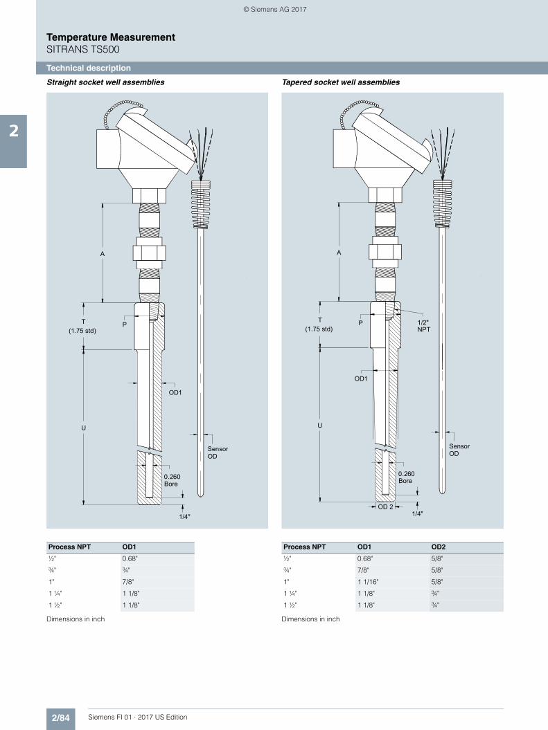
2/84 Siemens FI 01 · 2017 US Edition
Temperature MeasurementSITRANS TS500
Technical description
2
Straight socket well assemblies
Dimensions in inch
Tapered socket well assemblies
Dimensions in inch
Process NPT OD1
½" 0.68"
¾" ¾"
1" 7/8"
1 ¼" 1 1/8"
1 ½" 1 1/8"
Sensor OD
(1.75 std)
1/4"
0.260Bore
OD1
T
A
P
U
Process NPT OD1 OD2
½" 0.68" 5/8"
¾" 7/8" 5/8"
1" 1 1/16" 5/8"
1 ¼" 1 1/8" ¾"
1 ½" 1 1/8" ¾"
Sensor OD
(1.75 std)
OD1
OD 21/4"
0.260Bore
1/2"NPT
A
T P
U
© Siemens AG 2017

2/85Siemens FI 01 · 2017 US Edition
Temperature MeasurementSITRANS TS500
Technical description
2
General purpose sensors
Dimensions in inch
L
1/2" x 1/2" NPTDouble Ended Hex 316SS Fitting
Welded
L
Adjustable
Fitting
Optional 316SS
Compression
1/2" x 1/2" NPT AdjustableDouble Ended Hex 316SS Fitting
L
SpringLoaded
© Siemens AG 2017

2/86 Siemens FI 01 · 2017 US Edition
Temperature MeasurementSITRANS TS500
Technical description
2
Components: Connection head
Connection head
The connection head protects the wiring connections. The con-nection head features sufficient room for mounting a terminal block or transmitter.
Different connection heads are used depending on the applica-tion and preference.
Components: Measuring insert
Measuring inserts feature a large spring range. These measur-ing inserts are ideal for use with NPT threads with the typical loose tolerances. In this configuration, the extension function is partially or fully integrated (nipple-union-nipple). Moreover it is also possible to directly attach field devices, e.g. SITRANS TF.
Components: Transmitters
SITRANS TH head transmitters process the weak non-linear sen-sor signals and transmit a stable and temperature-linear stan-dard signal, thereby minimizing sensor signal disruptions.
The transmitters constantly monitor the temperature sensors and transmit diagnostic data to superordinate systems.
Because of the low energy feed of the SITRANS TH head trans-mitters, self-heating of the temperature sensors can be main-tained at minimal levels.
The electrical isolation and integrated cold junction ensure that temperature sensors with thermocouples provide reliable mea-surements at a low cost.
SITRANS TH product family
For detailed technical data on the SITRANS TH transmitters, please refer to the catalog FI 01.• TH100 - the basic device
- Output 4 to 20mA- for Pt100- can be configured using simple software
• TH200 - the universal device - Output 4 to 20mA- Resistance thermometer, thermocouples- can be configured using simple software
• TH300 - HART universal - Output 4 to 20 mA/HART- Resistance thermometer, thermocouples- HART conforming- Diagnostic functions
• TH400 - Fieldbus PA and FF - Output PROFIBUS PA or FOUNDATION Fieldbus- Resistance thermometer, thermocouples- Diagnostic functions; for detailed technical description of the
SITRANS TH transmitter please refer to the related chapter of this catalog.
Measuring technology: Sensor elements
The diverse application spectrum for industrial temperature measuring technology requires different sensor technologies.
Resistance thermometer
Sensor elements made of other basic materials with different nominal resistances or different underlying standards are avail-able on request. Resistance thermometers can be classified as follows:• Basic design:
The sensor element is built with thin layer technology. The resistance material is applied in the form of a thin layer on a ceramic carrier material.
• Versions featuring increased vibration-resistance:In addition to the basic design, the vibration resistance is improved through extra measures.
• Versions with expanded measuring range:Elements in wire-wound design. The wire winding is embed-ded in a ceramic body.
Thermocouples
Other thermocouples based on other thermo couples or under-lying standards are available upon request.
The most common base metal thermocouples include:• Type K (NiCr-Ni) more stable than type J, but drifts in upper
range.• Type J (Fe-CuNi) narrow application band
Measuring technology: Measuring range
The measuring range describes the temperature limits within which the thermometer can be used in a way that is meaningful for measurement purposes. Depending on the loads present, the thermowell materials and the desired accuracy levels, the actual application range for the thermometer may be smaller.
Resistance thermometer [°C (°F)]
Basic version and increased vibration resistance
-50 ... +400 (-58 ... +752)
Expanded measuring range -196 ... +600 (-320.8 ... +1112)
Thermocouple [°C (°F)]
Type K -40 ... +1000 (-40 ... +1132)
Type J -40 ... +750 (-40 ... +1382)
© Siemens AG 2017
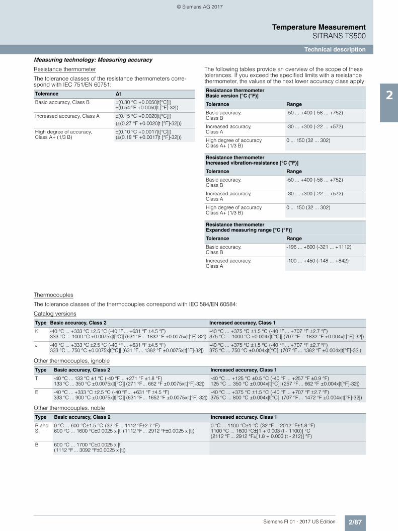
2/87Siemens FI 01 · 2017 US Edition
Temperature MeasurementSITRANS TS500
Technical description
2
Measuring technology: Measuring accuracy
Resistance thermometer
The tolerance classes of the resistance thermometers corre-spond with IEC 751/EN 60751:
The following tables provide an overview of the scope of these tolerances. If you exceed the specified limits with a resistance thermometer, the values of the next lower accuracy class apply:
Thermocouples
The tolerance classes of the thermocouples correspond with IEC 584/EN 60584:
Catalog versions
Other thermocouples, ignoble
Other thermocouples. noble
Tolerance ∆t
Basic accuracy, Class B ±(0.30 °C +0.0050|t[°C]|)±(0.54 °F +0.0050|t [°F]-32|)
Increased accuracy, Class A ±(0.15 °C +0.0020|t[°C]|)(±(0.27 °F +0.0020|t [°F]-32|))
High degree of accuracy, Class A+ (1/3 B)
±(0.10 °C +0.0017|t[°C]|)(±(0.18 °F +0.0017|t [°F]-32|))
Resistance thermometerBasic version [°C (°F)]
Tolerance Range
Basic accuracy, Class B
-50 ... +400 (-58 ... +752)
Increased accuracy, Class A
-30 ... +300 (-22 ... +572)
High degree of accuracyClass A+ (1/3 B)
0 ... 150 (32 ... 302)
Resistance thermometerIncreased vibration-resistance [°C (°F)]
Tolerance Range
Basic accuracy, Class B
-50 ... +400 (-58 ... +752)
Increased accuracy, Class A
-30 ... +300 (-22 ... +572)
High degree of accuracyClass A+ (1/3 B)
0 ... 150 (32 ... 302)
Resistance thermometerExpanded measuring range [°C (°F)]
Tolerance Range
Basic accuracy, Class B
-196 ... +600 (-321 ... +1112)
Increased accuracy, Class A
-100 ... +450 (-148 ... +842)
Type Basic accuracy, Class 2 Increased accuracy, Class 1
K -40 °C ... +333 °C ±2.5 °C (-40 °F ... +631 °F ±4.5 °F)333 °C ... 1000 °C ±0.0075x|t[°C]| (631 °F ... 1832 °F ±0.0075x|t[°F]-32|)
-40 °C ... +375 °C ±1.5 °C (-40 °F ... +707 °F ±2.7 °F)375 °C ... 1000 °C ±0.004x|t[°C]| (707 °F ... 1832 °F ±0.004x|t[°F]-32|)
J -40 °C ... +333 °C ±2.5 °C (-40 °F ... +631 °F ±4.5 °F)333 °C ... 750 °C ±0.0075x|t[°C]| (631 °F ... 1382 °F ±0.0075x|t[°F]-32|)
-40 °C ... +375 °C ±1.5 °C (-40 °F ... +707 °F ±2.7 °F)375 °C ... 750 °C ±0.004x|t[°C]| (707 °F ... 1382 °F ±0.004x|t[°F]-32|)
Type Basic accuracy, Class 2 Increased accuracy, Class 1
T -40 °C ... 133 °C ±1 °C (-40 °F ... +271 °F ±1.8 °F)133 °C ... 350 °C ±0.0075x|t[°C]| (271 °F ... 662 °F ±0.0075x|t[°F]-32|)
-40 °C ... +125 °C ±0.5 °C (-40 °F ... +257 °F ±0.9 °F)125 °C ... 350 °C ±0.004x|t[°C]| (257 °F ... 662 °F ±0.004x|t[°F]-32|)
E -40 °C ... +333 °C ±2.5 °C (-40 °F ... +631 °F ±4.5 °F)333 °C ... 900 °C ±0.0075x|t[°C]| (631 °F ... 1652 °F ±0.0075x|t[°F]-32|)
-40 °C ... +375 °C ±1.5 °C (-40 °F ... +707 °F ±2.7 °F)375 °C ... 800 °C ±0.004x|t[°C]| (707 °F ... 1472 °F ±0.004x|t[°F]-32|)
Type Basic accuracy, Class 2 Increased accuracy. Class 1
R and S
0 °C ... 600 °C±1.5 °C (32 °F ... 1112 °F±2.7 °F)600 °C ... 1600 °C±0.0025 x |t| (1112 °F ... 2912 °F±0.0025 x |t|)
0 °C ... 1100 °C±1 °C (32 °F ... 2012 °F±1.8 °F)1100 °C ... 1600 °C±[1 + 0.003 (t - 1100)] °C (2112 °F ... 2912 °F±[1.8 + 0.003 (t - 212)] °F)
B 600 °C ... 1700 °C±0.0025 x |t|(1112 °F ... 3092 °F±0.0025 x |t|)
© Siemens AG 2017

2/88 Siemens FI 01 · 2017 US Edition
Temperature MeasurementSITRANS TS500
Technical description
2
Measuring technology: Connection types
In the case of resistance thermometers, the type of sensor con-nection directly affects the level of accuracy:
Two-wire system
The resistance of sensor lines are included in the measurement result as an error. Adjustments are recommended in this case.
Pt100 Two-wire system
Three-wire system
Line resistance is not included in the measurement result. Re-quirements: all terminal and line resistances (corrosion) are at the same level, and terminals are at the same temperature level.
Pt100 Three-wire system
Four-wire system
Line resistance is not included in the measurement result. This type of connection is the most secure and most accurate.
Pt100 Four-wire system
Siemens measuring inserts can be used to implement all types of connections for 1 x Pt100 devices. In the case of 2 x Pt100 ver-sions, two- and three-wire systems are also possible. For mea-surement-related reasons, we always recommend a 1 x four-wire or 2 x 3-wire connection.
Pt100
Pt100
Pt100
© Siemens AG 2017

2/89Siemens FI 01 · 2017 US Edition
Temperature MeasurementSITRANS TS500
Technical description
2
Thermowell calculation
Properly applied load diagrams will provide a sufficient degree of safety for the most common thermowell configurations.
However, there are cases in which operating conditions deviate too greatly from standard parameters. In this case, a customized thermowell calculation may be required.
Another reason for doing this calculation is the fact that flowing media can create turbulence at the tip of the thermowell under certain conditions. The thermowell will then vibrate and may even be destroyed if not configured correctly. This is the most frequent cause of thermowell bailure.
SIEMENS offers the two recognized methods for calculating the thermowell:• DIN/Dittrich method• ASME/Murdock method
This method also takes into account turbulence formation on a mathematical level.
Both methods provide a high degree of safety with regard to thermowell configuration, however, they do not provide a guar-antee against breakdowns.
Materials
Where cost-intensive materials are used with flange thermowells, cost savings can be achieved by using a so-called flanged wheel. A thin disc of the material which comes into contact with media is applied prior to the flange (ordinary stainless steel).
Vibration resistance of measuring insert, cable sensor
Similar to the thermowell, inner (Karman vortices) and outer (plant) vibrations also affect the measuring insert. For this rea-son, a special assembly of measurement elements is required. Other than a few exceptions for cable and compact thermome-ters, Siemens only produces sensors based on a mineral-insu-lated cable. Together with precautions taken when installing the measuring element, the Siemens basic version already exceeds EN 60751 by more than a factor of 3. Pursuant to the measure-ment methods of this standard, the following values are obtained (tip-tip):• 10 g: Basic version and expanded measuring range• 60 g: Increased vibration-resistance and thermocouple
Electrical stabilityInsulation resistanceThe insulation resistance between each measuring circuit and the fitting is tested at a voltage of 500 V DC at room temperature.Riso ≥ 100 MΩDue to the property of the mineral-insulated cable, the insulation resistance decreases as temperature increases. Because of the special production method, it is, however, possible to achieve very good values even at high temperatures.Line resistanceWhen connected to two-wire systems, the line resistance is in-cluded in the measurement result. The following rule of thumb can be used:• ∅ Measuring insert 6 mm (0.24 in) 2.8 Ω/m or 44.78 (44.78 )For this reason a connection to three- or four-wire systems is highly recommended.
Material descriptions/Standards comparison Max. tem-perature [°C (°F)](unloaded)
Properties Applications
Mat. No.: AISI/Trade name:
EN 10028-2: Description
1.4404 or 1.4435
AISI 316 L X2CrNiMo17-12-2 Austenitic stain-less steel
600(1112)
Good acid resistance, resistant against grain boundary corro-sion
Chemical industry, waste treat-ment, paper and cellulose industry, food industry
2.4816 Inconel 600 NiCr15Fe Nickel-Chrome alloy
1150(2102)
Resistant at high tempera-tures, resistant against chlo-rine-induced cold crack corrosion
Chemical industry, petrochem-ical industry, food industry
1.4876 Incoloy 800 X10NiCrAlTi32-21 Austenitic heat-resistant stain-less steel
1100(2012)
Excellent resistance against oxidation and carbonization at high temperatures, good cor-rosion resistance
O&G industry, waste gas treat-ment, power plants (steam boiler, heat exchanger), appli-cations using aggressive fluids
2.4819 Hastelloy C 276 NiMo16Cr15W Nickel-Chrome-Molybdenum alloy
1100(2012)
Resistant at high tempera-tures, in oxidizing and reduc-ing atmosphere, resistant against pitting and crevice cor-rosion, good corrosion resis-tance after welding
Chemicals industry, paper and cellulose industry, waste treat-ment, waste incinerators, emis-sions controls, shipbuilding and offshore industry
2.4360 Monel 400 NiCu30Fe Nickel-Copper alloy
500(932)
Excellent corrosion resistance, particularly against chlorine-induced cold crack corrosion
Chemical industry, offshore industry, nuclear technology, petrochemical industry
© Siemens AG 2017
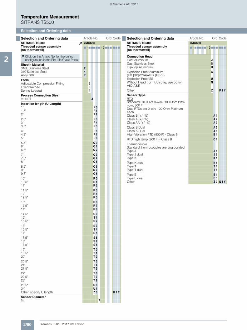
2/90 Siemens FI 01 · 2017 US Edition
Temperature MeasurementSITRANS TS500
Selection and Ordering data
2
Selection and Ordering data Article No. Ord. Code
SITRANS TS500 7MC650Threaded sensor assembly (no thermowell)
7 - 77777 - 0000 777 777
Click on the Article No. for the online configuration in the PIA Life Cycle Portal.
Sheath Material 316L Stainless Steel 2
310 Stainless Steel 4 Alloy 600 7
Form
Adjustable Compression Fitting 2 Fixed Welded 3 Spring-Loaded 4
Process Connection Size
½" NPT J Insertion length (U-Length)
1" P 0 1.5" P 1 2" P 2
2.5" P 3 3" P 4 3.5" P 5
4" P 6 4.5" P 7 5" P 8
5.5" Q 0 6" Q 1 6.5" Q 2
7" Q 3 7.5" Q 4 8" Q 5
8.5" Q 6 9" Q 7 9.5" Q 8
10" R 0 10.5" R 1 11" R 2
11.5" R 3 12" R 4 12.5" R 5
13" R 6 13.5" R 7 14" R 8
14.5" S 0 15" S 1 15,5" S 2
16" S 3 16.5" S 4 17" S 5
17.5" S 6 18" S 718.5" S 8
19" T 019.5" T 120" T 2
20.5" T 321" T 421.5" T 5
22" T 622.5" T 723" T 8
23.5" U 024" U 1
Other, specify U length Z 0 K 1 Y
Sensor Diameter ¼" 7
Connection HeadCast Aluminum JCast Stainless Steel SFlip-Top Aluminum B
Explosion Proof Aluminum (FM [XP]/CSA/ATEX [Ex d])
G
Explosion Proof SS UWithout Head (for TF/display, use option A80-A83)
N
Other Z P 1 Y
Sensor TypeRTD Standard RTDs are 3-wire, 100 Ohm Plati-num, 500 FDual RTDs are 2-wire 100 Ohm Platinum eachClass B (+/- %) A 1Class A (+/- %) A 2Class AA (+/- %) A 3
Class B Dual A 5Class A Dual A 6High Vibration RTD (900 F) - Class B B 1
RTD high temp (900 F) - Class B C 1
ThermocoupleStandard thermocouples are ungroundedType J J 1Type J dual J 5Type K K 1
Type K dual K 5Type T T 1Type T dual T 5
Type E E 1Type E dual E 5Other Z 0 Q 1 Y
Selection and Ordering data Article No. Ord. Code
SITRANS TS500 7MC650Threaded sensor assembly (no thermowell)
7 - 77777 - 0000 777 777
FI01_2017_us_kap02_SITRANS_TS.fm Seite 90 Mittwoch, 16. August 2017 8:22 08
© Siemens AG 2017

2/91Siemens FI 01 · 2017 US Edition
Temperature MeasurementSITRANS TS500
Selection and Ordering data
2
Selection and Ordering data Order Code
OptionsAdd "-Z" to Article No. and add options, separate extensions with "+".
Explosion protection
ATEX Intrinsic safety "ia", "ic" E01
ATEX Flameproof enclosure "d" E02
ATEX Non sparking "n" E03
cFMus intrinsic safety E11
cFMus explosion proof E13
Transmitter mounted in headMeasuring range to be set must be specified with plain text data "Y01".
SITRANS TH100 No Approvals T10
SITRANS TH100 ATEX (Ex ia, Ex n) T11
SITRANS TH100 FM (IS) T13
SITRANS TH200 No Approvals T20
SITRANS TH200 ATEX (Ex ia, Ex n) T21
SITRANS TH200 FM (IS) T23
SITRANS TH300 No Approvals T30
SITRANS TH300 ATEX (Ex ia, Ex n) T31
SITRANS TH300 FM (IS) T33
SITRANS TH400 PA No Approvals T40
SITRANS TH400 PA FM (IS), ATEX (Ex ia, Ex n) T41
SITRANS TH400 FF No Approvals T45
SITRANS TH400 FF FM (IS), ATEX (Ex ia, Ex n) T46
Transmitter with display - SITRANS TF
With SITRANS TH200 (SIPROM T communication)
General Purpose [7NG3135-0AC10] A81
XP FM/CSA (XP) [7NG3135-5AC10] A82
With SITRANS TH300 (HART Communication)
General Purpose [7NG3136-0AC10] A83
XP FM/CSA (XP) [7NG3136-5AC10] A84
Other temperature transmitter (TF280, TF PA, etc)
Mounting of transmitter - Ordered separately A80
Transmitter Configuration
Specify measuring range in plain text Y01
Specify HART-address (max. 8 characters) in plain text
Y17
Tag Number (max. 16 characters) - TF only Y23
Tag Description (max. 27 characters) - TF only Y24
Specify bus address in plain text Y25
Fail-safe value 3.6 mA (instead of 22.8 mA) U36
Certificates
Material certificate for wetted parts C12
Cert SIL 2 C20
Cert SIL 2/3 C23
Factory calibration - sensor only Y33
Factory cal - matched pair C15
Factory cal - sensor/transmitter assembly Y35
Sensor options
Grounded T/C (std = ungrounded) G31
4-wire RTD (std = 3-wire) R04
Further options
SS tag plate - wired to sensor assembly (connection head only)
Y15
Special option (define in plain text: "Y99:…") Y99
© Siemens AG 2017

2/92 Siemens FI 01 · 2017 US Edition
Temperature MeasurementSITRANS TS500
Selection and Ordering data
2
Selection and Ordering data Article No. Ord. Code
SITRANS TS500 7MC652Barstock Thermowell Assembly
7 - 77777 - 0007777 777
Click on the Article No. for the online configuration in the PIA Life Cycle Portal.
Well Material 316 SS 2
Special Version (Y99 required) 8
Thermowell Process Connection Type & Size
Threaded Thermowell ½" NPT 1 J
¾" NPT 1 K1" NPT 1 L
Flanged Thermowell1.0" 150# RF 2 E1.0" 300# RF 2 F1.5" 150# RF 2 G
1.5" 300# RF 2 H2.0" 150# RF 2 J2.0" 300# RF 2 K
3.0" 150# RF 2 P3.0" 300# RF 2 Q
Socket Weld Thermowell¾" Socket Weld 0 K1" Socket Weld 0 L
Other designCustomer-specified connection (Specify in plain text)
9 X H 1 Y
Thermowell Form
Straight S Tapered TStep-Down (Reduced) UOther, Specify themowell form, U-length and T-Length
Z 8 8 K 1 Y
Insertion length (U-Length), with standard T-length (1.75")
2" 1 2 2.5" 1 3 3" 1 4
3.5" 1 5 4" 1 6 4.5" 1 7
5" 2 0 5.5" 2 1 6" 2 2
6.5" 2 3 7" 2 4 7.5" 2 5
8" 2 6 8.5" 2 7 9" 3 0
9.5" 3 1 10" 3 2 10.5" 3 3
11" 3 4 11.5" 3 5 12" 3 6
12.5" 3 7 13" 4 0 13.5" 4 1
14" 4 2 14.5" 4 3 15" 4 4
15,5" 4 5 16" 4 6 16.5" 4 7
17" 5 0 17.5" 5 1 18" 5 2
18.5" 5 319" 5 419.5" 5 5
20" 5 620.5" 5 721" 6 0
21.5" 6 122" 6 222.5" 6 3
23" 6 423.5" 6 524" 6 624,5" 6 7
Other, specify U length Z 8 8 K 1 Y
Extension (A-length)None 03" Hex nipple-union-nipple, SS (HUNS) 73" Nipple, SS (NS) 9 N 0 G
3" Nipple-union-nipple, galv. steel (NUN) 9 N 0 M3" Nipple-union-nipple, SS (NUNS) 9 N 0 N6" Nipple-union-nipple, galv. steel (NUN) 9 N 9 M
6" Nipple-union-nipple, SS (NUNS) 9 N 9 N6" Hex nipple-union-nipple, SS (HUNS) 9 N 9 HOther 9 N 8 Y
Connection HeadCast Aluminum JCast Stainless Steel SFlip-Top Aluminum B
Explosion Proof Aluminum (FM [XP]/CSA/ATEX [Ex d])
G
Explosion Proof SS UWithout Head (for TF/display, use option A80) N
Other Z P 1 Y
Sensor TypeRTD Standard RTDs are 3-wire, 100 Ohm Plati-num, 500 FDual RTDs are 2-wire 100 Ohm Platinum eachClass B (+/- ### %) A 1Class A (+/- ### %) A 2Class AA (+/- ### %) A 3
Class B Dual A 5Class A Dual A 6High Vibration RTD (900 F) - Class B B 1
RTD high temp (900 F) - Class B C 1
ThermocoupleStandard thermocouples are ungroundedType J J 1Type J dual J 5Type K K 1
Type K dual K 5Type T T 1Type T dual T 5
Type E E 1Type E dual E 5
Other SensorOther, Specify type (Q1Y = …) Z 0 Q 1 Y
No SensorFor well-only configurations N 0
Selection and Ordering data Article No. Ord. Code
SITRANS TS500 7MC652Barstock Thermowell Assembly
7 - 77777 - 0007777 777
© Siemens AG 2017
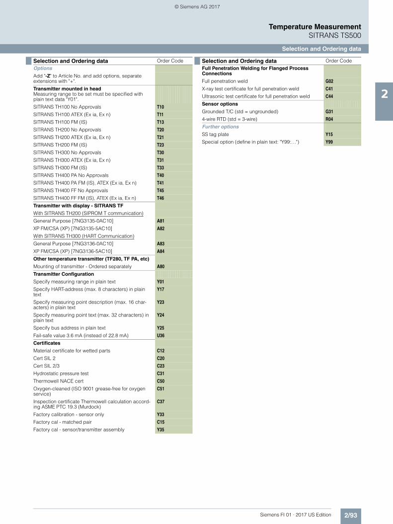
2/93Siemens FI 01 · 2017 US Edition
Temperature MeasurementSITRANS TS500
Selection and Ordering data
2
Selection and Ordering data Order Code
Options
Add "-Z" to Article No. and add options, separate extensions with "+".
Transmitter mounted in headMeasuring range to be set must be specified with plain text data "Y01".
SITRANS TH100 No Approvals T10
SITRANS TH100 ATEX (Ex ia, Ex n) T11
SITRANS TH100 FM (IS) T13
SITRANS TH200 No Approvals T20
SITRANS TH200 ATEX (Ex ia, Ex n) T21
SITRANS TH200 FM (IS) T23
SITRANS TH300 No Approvals T30
SITRANS TH300 ATEX (Ex ia, Ex n) T31
SITRANS TH300 FM (IS) T33
SITRANS TH400 PA No Approvals T40
SITRANS TH400 PA FM (IS), ATEX (Ex ia, Ex n) T41
SITRANS TH400 FF No Approvals T45
SITRANS TH400 FF FM (IS), ATEX (Ex ia, Ex n) T46
Transmitter with display - SITRANS TF
With SITRANS TH200 (SIPROM T communication)
General Purpose [7NG3135-0AC10] A81
XP FM/CSA (XP) [7NG3135-5AC10] A82
With SITRANS TH300 (HART Communication)
General Purpose [7NG3136-0AC10] A83
XP FM/CSA (XP) [7NG3136-5AC10] A84
Other temperature transmitter (TF280, TF PA, etc)
Mounting of transmitter - Ordered separately A80
Transmitter Configuration
Specify measuring range in plain text Y01
Specify HART-address (max. 8 characters) in plain text
Y17
Specify measuring point description (max. 16 char-acters) in plain text
Y23
Specify measuring point text (max. 32 characters) in plain text
Y24
Specify bus address in plain text Y25
Fail-safe value 3.6 mA (instead of 22.8 mA) U36
Certificates
Material certificate for wetted parts C12
Cert SIL 2 C20
Cert SIL 2/3 C23
Hydrostatic pressure test C31
Thermowell NACE cert C50
Oxygen-cleaned (ISO 9001 grease-free for oxygen service)
C51
Inspection certificate Thermowell calculation accord-ing ASME PTC 19.3 (Murdock)
C37
Factory calibration - sensor only Y33
Factory cal - matched pair C15
Factory cal - sensor/transmitter assembly Y35
Full Penetration Welding for Flanged Process Connections
Full penetration weld G02
X-ray test certificate for full penetration weld C41
Ultrasonic test certificate for full penetration weld C44
Sensor options
Grounded T/C (std = ungrounded) G31
4-wire RTD (std = 3-wire) R04
Further options
SS tag plate Y15
Special option (define in plain text: "Y99:…") Y99
Selection and Ordering data Order Code
© Siemens AG 2017
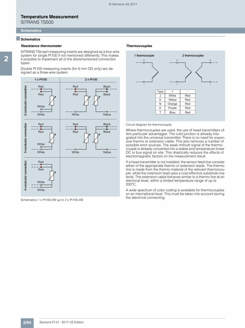
2/94 Siemens FI 01 · 2017 US Edition
Temperature MeasurementSITRANS TS500
Schematics
2
■ Schematics
Resistance thermometer
SITRANS TSinsert measuring inserts are designed as a four-wire system for single Pt100 if not mentioned differently. This makes it possible to implement all of the aforementioned connection types.
Double Pt100 measuring inserts (for 6 mm OD only) are de-signed as a three-wire system.
Schematics 1 x Pt100-2W up to 2 x Pt100-4W
Thermocouples
Circuit diagram for thermocouple
Where thermocouples are used, the use of head transmitters of-fers particular advantages: The cold junction is already inte-grated into the universal transmitter. There is no need for expen-sive thermo or extension cable. This also removes a number of possible error sources. The weak millivolt signal of the thermo-couple is already converted into a stable and temperature-linear DC or bus signal on site. This drastically reduces the effects of electromagnetic factors on the measurement result.
If a head transmitter is not installed, the sensor feed line consists either of the appropriate thermo or extension leads. The thermo line is made from the thermo material of the relevant thermocou-ple, while the extension lead uses a cost-effective substitute ma-terial. The extension cable behaves similar to a thermo line at an electrical level, within a limited temperature range of up to 200°C.
A wide spectrum of color coding is available for thermocouples on an international level. This must be taken into account during the electrical connecting.
2-co
nduc
tor c
onne
ctio
n2-
cond
ucto
r con
nect
ion
3-co
nduc
tor c
onne
ctio
n3-
cond
ucto
r con
nect
ion
4-co
nduc
tor c
onne
ctio
n4-
cond
ucto
r con
nect
ion
Red Red Black
Red Red Black
White
White
White Yellow
Red Red Black
Red Red Black
White
White
White Yellow
Red
Red
White
White
2 x Pt1002 x Pt1001 x Pt1001 x Pt100
+TypeWhiteJYellowKOrangeNPurpleEBlueT
-RedRedRedRedRed
2 thermocouples2 thermocouples1 thermocouple1 thermocouple+ + +
- - -
© Siemens AG 2017

2/95Siemens FI 01 · 2017 US Edition
Temperature MeasurementSITRANS TS500
Schematics
2
1) With an intrinsically safe line as per IEC 584-3, the sheath is always blue.2) For thermo lines as per ANSI MC96, the sheath is always blue.
Transmitters
In addition, our transmitters also allow for a large number of other possible connections (e.g. difference, average, two sen-sors). More information can be obtained at: http://www.usa.siemens.com/temperature
Country
International/Germany
North America UK/Czech Republic
Stan-dard
Not intrinsically safe1)
Extension lead2) BS 1843
Jacket + - Jacket + - Jacket + -
N PN PN WH OG OG RD OG OG BU
K GN GN WH YE YE RD RD BR BU
J BK BK WH BK WH RD BK YE BU
T BR BR WH BU BU RD BU WH BU
E VT VT WH VT VT RD BR BR BU
R+S OG OG WH BK RD GN WH BU
B GY GY WH GY GY RD - - -
Country
Netherlands Japan France
Stan-dard
DIN 43714 ISC 1610-198 NF C42-323
Jacket + - Jacket + - Jacket + -
N GN RD GN BU RD WH VT VT YE
K BU RD BU YE RD WH BK BK YE
J BR RD BR BR RD WH BU BU YE
T BK RD BK VT RD WH OG OG YE
E WH RD WH BK RD WH GN GN YE
R+S GY RD GY GY RD WH - - -
B GN RD GN BU RD WH VT VT YE
Abbreviation for colors
BK: black BR: brown BU: blue GD: gold GN: green
GY: gray OG: orange PN: pink RD: red SR: silver
TQ: tur-quoise
VT: violet WH: white YE: yellow
© Siemens AG 2017

2/96 Siemens FI 01 · 2017 US Edition
Temperature Measurement
Notes
2
© Siemens AG 2017