Embed Size (px)
Citation preview

Heriot-Watt University Research Gateway
Heriot-Watt University
Catastrophic crystal growth of clathrate hydrate with a simulated natural gas system during apipeline shut-in conditionSundramoorthy, Jega Divan; Sabil, Khalik Mohamad; Lal, Bhajan; Hammonds, Paul
Published in:Crystal Growth and Design
DOI:10.1021/cg501626h
Publication date:2015
Document VersionEarly version, also known as pre-print
Link to publication in Heriot-Watt University Research Portal
Citation for published version (APA):Sundramoorthy, J. D., Sabil, K. M., Lal, B., & Hammonds, P. (2015). Catastrophic crystal growth of clathratehydrate with a simulated natural gas system during a pipeline shut-in condition. Crystal Growth and Design,15(3), 1233-1241. DOI: 10.1021/cg501626h
General rightsCopyright and moral rights for the publications made accessible in the public portal are retained by the authors and/or other copyright ownersand it is a condition of accessing publications that users recognise and abide by the legal requirements associated with these rights.
If you believe that this document breaches copyright please contact us providing details, and we will remove access to the work immediatelyand investigate your claim.

Download date: 23. Jun. 2018

Catastrophic Crystal Growth of Clathrate Hydrate with a SimulatedNatural Gas System during a Pipeline Shut-In ConditionJega Divan Sundramoorthy,† Khalik M. Sabil,*,# Bhajan Lal,§ and Paul Hammonds‡
†Baker Hughes (M) Sdn. Bhd, 207 Jalan Tun Razak, 50400 Kuala Lumpur, Federal Territory of Kuala Lumpur, Malaysia#Institute of Petroleum Engineering, Heriot-Watt University Malaysia, Precinct 2, 62100, Putrajaya, Federal Territory of Putrajaya,Malaysia§Chemical Engineering Department, Universiti Teknologi PETRONAS, Bandar Seri Iskandar, 31750 Tronoh, Perak, Malaysia‡Cairn India Ltd., Vipul Plaza, Sun City, Sector 54, Gurgaon 1222002, Haryana, India
ABSTRACT: This paper presents a significant finding where capillary-aided catastrophic gas hydrate growth is observed under a shut-in condi-tion (static fluid) for an uninhibited system. With the use of a newlydesigned apparatus, consisting of six units of identical rocking cell,nucleation and growth are observed. All experiments are conducted underisochoric conditions using 11.0 K subcooling (ΔTsub) as a driving force. Asimulated natural gas mixture of 90.0 mol % methane + 10.0% mol %propane is used as a gas phase. The liquid phase used is 3% (Na+, Cl−)brine. The observations of the capillary-aided mass-transport mechanismfor a catastrophic gas hydrate growth are presented in this work. Ourobservations show hydrate crystal formation at a brine wetted area close tothe brine/gas interface initiates capillary-aided catastrophic hydrate growth.Moreover, no mass transfer restriction of brine toward catastrophic gashydrate growth is observed. Furthermore, our results show the denser (lessporous appearance) hydrate structures are continuously displaced from the hydrate−water interface (hydrate growth side). Thisdisplacement allowed new hydrate crystals to be formed uninterruptedly until the exhaustion of water in the cells. On the basis ofmacroscopic observations, the capillary-aided mass-transport mechanism for a catastrophic gas hydrate growth is presented.
1. INTRODUCTION
Clathrate hydrates or gas hydrates are nonstoichiometriccrystalline compounds that are formed in mixtures of waterand nonpolar or slightly polar low molecular weight gases orvolatile liquids when subjected to extreme conditions of highpressures and low temperatures.1 There are three commonlystudied gas hydrate structures that can be formed according tothe guest molecule size: cubic structure I (sI), cubic structure II(sII) and hexagonal structure H (sH).2−4 Recently, novelhydrate-related technologies have attracted attention in theenergy and environmental fields. Some of these technologies areused in practical application such as energy transport and storageof gases, refrigeration and gas separation.4 Moreover, natural gasdeposits in the ocean permafrost, ocean trenches and continentalmargins is suggested to provide a possible energy source in thefuture.2,5
In the petroleum industry, formation of a gas hydrate in oiland gas transmission lines leads to catastrophic economiclosses, pipeline blockages, and ecological risk as well as safetyhazards.3,6,7 The significance of preventing such losses due topipeline blockages has initiated a new discipline of engineeringknown as flow assurance.3 One of the main responsibilities offlow assurance engineering is to analyze risk associated with thepresence of solids, such as gas hydrates. With advancing researchand development over the past two decades, a more economical
and environmental friendly hydrate risk management systemusing chemicals such as low-dosage hydrate inhibitors (LDHI)has emerged. The use of LDHIs (less than 1 wt % of water) issignificantly cheaper and less hazardous compared to using thetraditional hydrate prevention method with chemicals such asthermodynamic inhibitors (methanol or glycol) where thedosage can be as high as 60 wt % of water.2 These LDHIs aredesigned either to delay hydrate formation (kinetic inhibitors) orto allow a controlled hydrate formation to occur in a dispersedflowing form (antiagglomerates).2,3 Increasing demand of energyis challenging the petroleum industry to explore and produce oiland gas from more extreme environments with higher pressuresand lower temperatures that fall far under the gas hydrateformation favorable conditions. Clearly, the advancement of thepetroleum industry to produce from extreme environments isleaving more room for investigating the potential of gas hydrateformation risk under various production conditions.To prevent or manage gas hydrate formation risks, the in-
depth understanding of hydrate growth mechanism isimportant.8−10 The general consensus is the formation of gashydrate crystals alone will not guarantee a gas hydrate blockage
Received: November 5, 2014Revised: January 5, 2015Published: January 13, 2015
Article
pubs.acs.org/crystal
© 2015 American Chemical Society 1233 DOI: 10.1021/cg501626hCryst. Growth Des. 2015, 15, 1233−1241

to occur in petroleum transmission lines.2 The root causeidentified for gas hydrate blockage in petroleum transmissionlines is the gas hydrate crystals’ ability to agglomerate whilerapidly growing to a point where a cross-section of a pipeline isblocked. Therefore, hydrate growth kinetics is the main problemin hydrate risk management. Knowing the significance of gashydrate growth kinetics to cause a blockage, in-depth under-standing of hydrate kinetic mechanism is important. It has beenpointed out that hydrate kinetics are governed by the transportmechanism of water and guest molecules toward a hydratecrystal.11,12 Noyes and Whitney stated that a crystal surface suchas a gas hydrate may provide a lower Gibbs energy that forms aboundary layer.13 This boundary layer then supports crystalgrowth through diffusion of solutes toward a crystal growth.13
Therefore, the crystal growth rate is determined by diffusionfrom the bulk concentration to the crystal interface. Withextensive research done to evaluate this hypothesis, a break-through is made using interferometry experiments.12−14
Researchers found physical evidence that shows the existenceof a boundary layer at a growing surface to allow diffusion.12−14
The importance of a high concentration gradient to accelerategas hydrate growth may be used to explain the tendency ofhydrate to form first at interfaces between the water-rich phaseand a guest molecule-rich phase, such as methane or CO2.
10,15−17
However, once a layer of gas hydrate forms at the gas−waterinterface (static condition), further gas hydrate formation isreported to be retarded with no further growth.11 A similarobservation by other researchers leads to a suggestion that over aperiod of time, the hydrate layer growing at the gas−waterinterface may become less porous, which then slowly restrictsmass transfer of water and guest molecules through the hydratelayer causing a hydrate growth to cease.11,12,18,19 Breakthroughexperimental work pioneered by Staykova12 using FE-SEMimaging on gas hydrate structure found evidence that hydrate
pores can transport water and gas. Therefore, this findingstrengthens the hypothesis that if a hydrate pore becomes lesspermeable at the hydrate−water interface, mass-transportrestriction will deplete the high concentration gradient of guestmolecules necessary in bulk water to support further gas hydrategrowth.11,12,18,19
The fundamental knowledge acquired from gas hydrategrowth morphology is significant in industrial processoptimization, where prediction of macroscopic flow or transportcharacteristics may be possible.20,21 Among them, the discoveryof different morphologies of hydrate crystals at the gas−waterinterface has been observed at different degrees of subcool-ing.9,10,22 This observation has been noted for static5,6,9,11 andalso dynamic conditions.19−21 Some reportedmorphological stud-ies relevant to natural gas conditions also show that changes ofhydrate structure are possible under different conditions.10,22
However, to the best of our knowledge, the influence of differenthydrate morphology found9,10,22 on gas hydrate growth kineticsor mass transfer efficiencies is still not known.Moreover, findingson the simulated hydrate growth mechanism that may explaincatastrophic gas hydrate growth under shut-in conditions (static)in natural gas pipelines could not be found from related literature.This paper thus aims to report on the macroscopic
observations made during a catastrophic gas hydrate growthfor a simulated natural gas system under a shut-in condition(static). To mimic shut-in conditions, all the observations arecarried out at a driving force of 11.0 K subcooling (ΔTsub), whichis similar to a gas transmission line that has been shut-in at sea-bed temperature (284.15 K). The chosen chemical compositionand experimental parameter in this work are close to an actualdeep-water gas production transmission line that has a previoushistory of gas hydrate formation. Lastly, the catastrophic growthmechanism in a simulated natural gas system is presented anddescribed.
Figure 1. Schematic diagram of the experimental apparatus.
Crystal Growth & Design Article
DOI: 10.1021/cg501626hCryst. Growth Des. 2015, 15, 1233−1241
1234

2. EXPERIMENTAL APPARATUS AND PROCEDURESMaterials. A premix gas mixture of 90% molar methane and 10%
molar propane with 98% purity from National Oxygen Pte Ltd. is usedin this experiment. Sodium chloride with >99% purity for brinepreparation was purchased from Sigma-Aldrich. Distilled and deionizedwater was used in throughout this experiment.Apparatus. Figure 1 is the schematic of the experimental apparatus
used for this present paper. The newly designed apparatus consists of sixunits of identical rocking cells. Each cell is made of durable sapphire glassto allow visibility for both the naked eye and also an online video camerato capture the reaction while working with high pressure up to 150 bar.Glass ball with a selected diameter is inserted in the cell to provideenhanced mixing of brine and gas before the experiment is started. Ahard Teflon chemical resistant gasket is selected to seal the reactorensuring no gas escaped from the high pressure reactor. Temperaturemeasurements are made using a IMF Electronics RTD thermoprobe(TT0281) with an accuracy of ±0.15 K up to 160 bar. Pressure mea-surements are made with IMF Electronics pressure transducer(PT3541) with an accuracy of ±1.0% up to 400 bar. Total volume ofthe high pressure cell is 21.0 mL. Temperature control for this experi-ment is a custom designed air flow chamber for precise temperaturecontrol in cells and between cells. The environment control cabinetalso holds a 6 high definition digital Moxa camera installed on the rearside of cell to have visual recording during experiments. A custom designrocking mechanism and ball count mechanism are also part of thetemperature control chamber. The cells are mounted on a customdesign rocking mechanism. All the functions and measurements arecontrolled by a programmable logic controller (PLC) integrated totailored comprehensive software.Experimental Procedures. Stringent cleaning work is applied for
cell preparation and cell assembly, ensuring all wetting parts of the cellare ultra-clean. A vacuum is applied to remove impure air inside the cell.10 mL of preweighted 3% brine is carefully injected into each cell, andthe syringe is reweighted again. The 10.0 mL volume occupies 50% ofthe cell total volume. Premixed gas is pumped into the cells until a stablepressure of 40 ± 2% bar is achieved. The cells are then mounted ona custom design rocking mechanism. The environmental chamber isthen vacuumed to remove moisture from air in the temperature controlchamber before it is prefilled with dry nitrogen gas. Before a hydrateformation experiment for a shut-in condition starts, the cells aresubjected to dynamic condition aided by the rocking mechanism andglass ball for 24 h. This is to allow good mixing between brine andpremixed gas. After 24 h, rocking is stopped to simulate a shut-incondition. The cell composition is rapidly cooled at a rate of 0.24 K/min.This temperature gradient is similar to one of the selected subseapipeline shut-in cooling gradients. The system is kept atΔTsub of 11.0 K(subcooling from sea-bed temperature) for 24 h for each experiment. Byutilizing CSMGem,11 it is determined only sII gas hydrates were formedin the experimental cells. Upon completion of the 24 h shut-in period at11.0 K ΔTsub, the cells are heated to 10.0 K higher than the hydratedissociation temperature for a few hours. This is done to dissociatethe gas hydrate formed in the cells. Experiments are then repeated forfive cycles with two identical cells for each cycle. Upon completion offive cycles, a new batch of the same chemical composition is charged intothe cell after cleaning the cell. The experiments are then repeatedagain five times for catastrophic hgas hydrate growth measurement.The subcooling here is the difference between sea-bed temperature(277.0 K) and our cells hydrate equilibrium temperature (288.0 K)determined by experimental work separate from this work. In allexperiments, visual observation is made with the cell positioned at30 degree inclinations. Thirty degree inclination is the standard positionof the cell when the rocking mechanism is stopped. In this work, the cellcomposition consists of 10.0 mL of 3.0% wt NaCl with a gas pressure of40 ± 2% bar of gas mixture.
3. RESULTS AND DISCUSSIONCatastrophic Hydrate Growth Initiation in the Vicinity
of Water Surface. Figure 2 is the close-up macroscopic viewpresented in time intervals to illustrate a typical capillary force
aided catastrophic growth mechanism found in this work. Thedetection of first gas hydrate structure in the bulk water isseen after 781 min exposed under an 11.0 K ΔTsub condition(Figure 2a). The first gas hydrate structure has a fine tangledfibrous appearance. After 4 min (Figure 2b), the tangled hydratefiber has slowly grown and branches to form a fibrous treerootlike structure as shown in Figure 2c. Similar to this presentwork (Figure 2b,c), earlier morphological work by Lee20 using amicroscope confirms that a tangled fibrous dendrite-like gashydrate structure will form in bulk water when the ΔTsub >7.5 K.The formation of a fibrous gas hydrate structure at the watersurface would be first thought to be a barrier for mass transfer.However, this was not the case observed from the experimentalwork. The fibrous structure did not evolve to form a diffusionbarrier at the gas−water interface as shown in Figure 2c. Instead,the growing dense fibrous structure retained sufficient porosityfor water mass transfer aided by capillary action toward thegrowing gas hydrate structure. Later in this experiment as shownin Figure 2d, a tiny water droplet (wetted surface) above thewater−gas interphase forms a hydrate crystal. Upon formationof a hydrate crystal on the 860th minute, a communication(hydrate crystal) to the nearby water bulk which has the tangledfibrous dendrite gas hydrate structure occurs. The communica-tion established between crystals adhered to sapphire glass andbulk water is the initiating point for a capillary transport for water(brine). As the hydrate formation continued on the sapphireglass surface, the water level started to decrease (Figure 2f−h).This indicates that a lot of water is necessary for gas hydrategrowth. As the water level recedes, the tangled fibrous dendritehydrate structures still remained and have a denser appearance.The fibrous tree root-like dendrite hydrate structures remaineduntil the exhaustion of free brine (Figure 2h). The dense fibrousstructure in the bulk water retained sufficient porosity for watermass transfer aided by capillary action toward the growing gashydrate structure. Finally, the capillary-aided mass transfer leadsto a catastrophic hydrate growth 887 min later (Figure 2h) afterthe detection of first gas hydrate structure. The phenomenaof gas hydrate growth observed (Figure 2d−h) above the bulkwater interface shows that gas hydrates have affinity to grow onsapphire glass. Furthermore, this observation on capillary actioninitiation (Figure 2d,e) is found to be similar to Henriksson’s23
work; initiation of a capillary force with surface energy differencesbetween two phases. Henriksson23 explained that a surface energydifference is created between water wet solid structure and bulkwater under a close vicinity. The surface energy difference thencreates a driving between a water wet solid and bulk water wherea capillary action is innitiated30 as observed in Figure 2d,e.Although Henriksson’s23 work is not related to gas hydrates, itcan be used to explained the capillary action initiated when awater wet gas hydrate crystal23,24 is formed in close vicinity to thebulk water as observed in this work (Figure 2d,e). Therefore, thesurface energy difference between water wet solid (gas hydrate)and bulk water creates a driving force for capillary-aided crystalgrowth. Furthermore, by forming more gas hydrates, reductionof Gibbs free energy for a favorable equilibrium condition canbe achieved.11 Therefore, this may have further enhanced theinitiated capillary action to carry on. As a result, a catastrophic gashydrate growth covering a large section of a sapphire glassoccurred as observed in this paper (Figure 2h).Since the capillary-aided catastrophic gas hydrate growth
mechanism extends beyond the area of gas−water interface,time interval macroscopic observation covering the entire cellsapphire interior is also conducted. The following sections in this
Crystal Growth & Design Article
DOI: 10.1021/cg501626hCryst. Growth Des. 2015, 15, 1233−1241
1235

paper will illustrate macroscopic observation of four separatecases where a capillary-aided catastrophic gas hydrate growth is
found in the vicinity of (a) gas−water interface, sapphire glass,and glass ball, (b) gas−water interface, sapphire, glass ball, and
Figure 2. Close-up view of a typical catastrophic growth mechanism.
Crystal Growth & Design Article
DOI: 10.1021/cg501626hCryst. Growth Des. 2015, 15, 1233−1241
1236
isolated gas hydrate structure, (c) gas−water interface, sapphire,and isolated gas hydrate structure, and (d) gas−water interface,sapphire, glass ball, and metal surface. Close up macroscopicimages in Figure 2 is revisited during image presentation anddiscussion of the four separate cases presented in this paper.
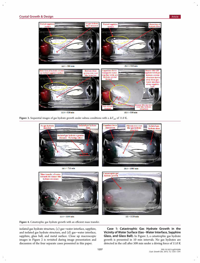
Case 1: Catastrophic Gas Hydrate Growth in theVicinity of Water Surface (Gas−Water Interface, SapphireGlass, and Glass Ball). In Figure 3, a catastrophic gas hydrategrowth is presented in 10 min intervals. No gas hydrates aredetected in the cell after 508 min under a driving force of 11.0 K
Figure 3. Sequential images of gas hydrate growth under subsea conditions with a ΔTsub of 11.0 K.
Figure 4. Catastrophic gas hydrate growth with an efficient mass transfer.
Crystal Growth & Design Article
DOI: 10.1021/cg501626hCryst. Growth Des. 2015, 15, 1233−1241
1237
ΔTsub. However, 10 min later in Figure 3b, the first hydratestructures are detected. Similar to the close-up picture inFigure 2a, this hydrate structure (Figure 3b) has a fine tangledfibrous appearance in the bulk phase. After 10 min (Figure 3b),the tangled hydrate fibers have slowly grown and branch to forma fibrous tree root-like structure, but with no massive growthinitiated. As soon as the wetted surface on the sapphire glassabove the gas−water interphases near to the glass ball formshydrate crystal on the 538th minute (Figure 3c) similar toFigure 2d; massive hydrate formation is initiated as shown inFigure 3d. Massive growth is continued with efficient watertransport upward (Figure 3d) from a liquid bulk toward thegrowing crystal which had adhered to the sapphire glass. Similarto Figure 2d−g, the dense fibrous hydrate structure in the bulkwater (Figure 3c,d) retained its porosity and did not stop themass transfer of water toward the growing hydrate structure.During hydrate growth (Figure 3d), new hydrate crystals areobserved to form near the gas−water interface. Interestingly,with a capillary-aided mass transfer, a unique gas hydrate crystal
growth mechanism is observed. The newly forming hydratecrystal near the bulk water is seen to push or displace the existing(older) crystals away from its birthplace (gas−water interface).The older hydrate crystal agglomerates along the sapphire walland are denser in appearance as shown during the 548th minute(Figure 3d). As a result, continued access of gas to the watersurface which provided the materials essential for further crystalgrow10,11,25 is possible under this unique crystal growthmechanism. Therefore, mass transfer restriction that retardsfurther hydrate growth due to porosity reduction at the gas−water interface10,11,16,24,26 is prevented with this unique gashydrate growth as shown in Figure 3d.
Case 2: Catastrophic Gas Hydrate Growth in theVicinity of Water Surface (Gas−Water Interface, Sap-phire, Glass Ball, and Isolated Gas Hydrate Structure).Figure 4 is sequential images of a capillary-aided catastrophic gashydrate growth that occurred without being triggered by anisolated mass of gas hydrate formed within the same experi-mental cell. A patch of hydrate mass is seen to form at a distance
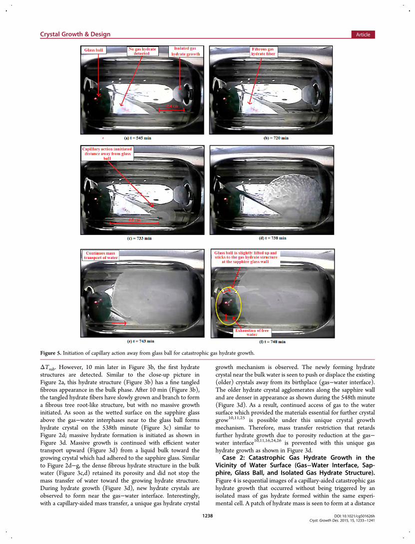
Figure 5. Initiation of capillary action away from glass ball for catastrophic gas hydrate growth.
Crystal Growth & Design Article
DOI: 10.1021/cg501626hCryst. Growth Des. 2015, 15, 1233−1241
1238

(2.6 cm) from bulk water as illustrated in Figure 4a. This is after711 min under ΔTsub of 11.0 K. There is no communication orany sort of reported bridge effect27,28 between the bulk water andthe isolated hydrate mass to trigger any gas hydrate growth in theliquid bulk. Similar to Figures 2d and 3c, when a gas hydratecrystal forms near the liquid interphase with the presence of afibrous tree root-like structure in the bulk water, a capillary-aidedgas hydrate growth is initiated 375 min later (Figure 4b).Figure 4c shows the repetition of observations made in Figure 3dwhere a unique growth mechanism is seen pushing the existingagglomerated crystals away from the interface along the sapphiresurface, while the mass transfer of water through the porousfibrous hydrate structure in the bulk water was continued. After1128min (Figure 4d), a catastrophic gas hydrate growth is noted.Case 3: Catastrophic Gas Hydrate Growth in the
Vicinity of Water Surface (Gas−Water Interface, Sap-phire, and Isolated Gas Hydrate Structure). Figure 5 showsthe sequential images of a capillary-aided catastrophic gas hydrategrowth occurring 4.3 cm away from the glass ball. Similar toFigure 4, isolated gas hydrate formed at a greater distance(2.4 cm) in Figure 5a did not initiate a gas hydrate growth
immediately in the bulk water. However, 175 min later(Figure 5b), a fibrous gas hydrate structure is detected in theliquid bulk. This time, a capillary-aided gas hydrate growth isinitiated at a wetted surface above a gas−water interface at agreater distance (4.3 cm) from the glass ball (Figure 5c). Uponcatastrophic gas hydrate growth 15 min later (Figure 5f), theglass ball is observed to be slightly lifted upward and sticking tothe sapphire glass wall opposite of the camera view. Masstransport until the point of free brine solution being exhaustedsimilar to Figures 2−4 is observed (Figure 5e,f). Moreover, eventhe last free brine located in a 30 degree gradient below thehydrate mass is transported to the hydrate mass until the freebrine is exhausted through the porous fibrous hydrate structurein the bulk water (Figure 5e,f). Even though the initial chemicalcomposition of the water before hydrate formation contains only3% brine (Na+ and Cl−), ions such as Na+ and Cl− are known tobe excluded from gas hydrate clathrates structures duringgrowth.11,24,29,30 Therefore, with increasing brine concentrationdue to ion exclusion during gas hydrate growth, the thermo-dynamic inhibition property of the brine would alsoincrease.11,23,28,29 If the driving force is insufficient with the
Figure 6. Surface tension disturbance during initiation of capillary action for catastrophic.
Crystal Growth & Design Article
DOI: 10.1021/cg501626hCryst. Growth Des. 2015, 15, 1233−1241
1239

increasing thermodynamic inhibition property of brine duringhydrate growth, further gas hydrate formation is expected tobe retarded at a certain stage.24,30 However, in this work, thecapillary-aided water transport observed continued until all freewater is exhausted (Figure 5f).Case 4: Catastrophic Gas Hydrate Growth in the
Vicinity of Water Surface (Gas−Water Interface, Sap-phire, Glass Ball, and Metal Surface). Figure 6 presents acapillary-aided catastrophic gas hydrate growth which started atthe metal wall (end-cap of the cell) just above the gas−waterinterface in a 3 min time interval. In Figure 6a, a meniscus isformed due to surface tension between water bulk and the metalwall. Despite the presence of a fibrous gas hydrate structurebelow the water−gas interface, the meniscus remainedundisturbed (Figure 6a).However, when a gas hydrate crystal is detected slightly
above the interface, the meniscus between gas−water interfaces(Figure 6b) is broken. This is followed by an efficient watertransport through the porous fibrous hydrate structure in thebulk water (Figure 6c−e) toward the growing gas hydrate growthstructure. The free brine is then exhausted while a catastrophicgas hydrate growth is observed (Figure 6f). Similar to thisobservation (Figure 6), researchers31,32 also found and explainedsimilar capillary action initiation in the area of hydrodynamics.Levich31 and Sphhocleous32 explained that any disturbance insurface tension may cause a meniscus to break leading toward acapillary action. The formation of water wet gas hydrate crystal inFigure 6b (similar to the close-up image in Figure 2d) slightlyabove the meniscus, caused the meniscus to break and a capillaryaction to be initiated. The capillary-aided mass transfer initiatedafter breaking the meniscus resulted in a catastrophic gas hydrategrowth 12min later (Figure 6g). Figure 7 is a pictorial illustrationpresented to provide better visual clarity of Figure 6a,b.
4. CONCLUSIONS
The capillary-aided catastrophic hydrate growth where a wholepipe cross section blocked due to hydrate formation under ashut-in condition is observed in the present work. Experimentswere conducted under a driving force of 11.0 K ΔTsub with asimulated natural gas mixture of 90.0 mol % methane + 10.0%mol % propane at pressure of 40 ± 2% bar. The novel aspect ofthis work is in how physical factors come into play in acceleratinggrowth beyond what would be expected from diffusion kinetics inthe water phase. Thus, these observations of capillary-aidedhydrate growth expand knowledge of the kinetics of crystalgrowth through detailed observation of the growth process. Theresults can be summarized as follows: (1) Hydrate crystalformation at a brine-wetted area close to the brine/gas interface
initiates capillary-aided catastrophic hydrate growth. This regionof hydrate crystal formation has fast transport of gas moleculesand rapid water transport through reduction in surface tensionand capillary effect under a shut-in condition. Furthermore, thecapillary action causes a large increase in water surface area forgas diffusion over a short range and maintains the supply of waterto the growing crystals. (2) Hydrate formation retardation due toincreasing concentration of brine (Na+ and Cl−) is not observed.Hydrate growth continued until all the visually seen water isexhausted. (3) The ability of new hydrate crystal growth pushingthe denser old formed hydrate crystal due to agglomeration awayfrom the growth zone does not allow decreasing porosity on adense hydrate mass as a growth limiting factor. This mechanismallows continues water transport to the growing hydratestructure via a capillary effect until the exhaustion of the water.(4) On the basis of morphology observations, the mechanism ofa capillary-aided catastrophic gas hydrate growth is presented.
■ AUTHOR INFORMATIONCorresponding Author*Phone: +603 88810918. Fax: +60388810194. E-mail:[email protected].
NotesThe authors declare no competing financial interest.
■ ACKNOWLEDGMENTSThe authors are grateful to Baker Hughes (M) Sdn. Bhd andUniversiti Teknologi PETRONAS for providing financialsupport and facilities. The authors would also like to thankDixson FA Engineering for their technical skills of fabrication ofrocking cell and support. Thanks also to Richard Bremer (ICSS/DCS) and Yeah Swee Lin (SCADA) for their contribution in thiswork.
■ REFERENCES(1) Ishida, Y.; Sakemoto, R.; Ohmura, R. Chem.Eur. J. 2011, 17,9471−9477.(2) Koh, C. A. Chem. Soc. Rev. 2001, 31, 157−167.(3) Sloan, E. D. Nature. 2003, 426, 353.(4) Seo, Y.; Kang, S. P. J. Petrol. Sci. Eng. 2012, 88−89, 61−66.(5) Anderson, R.; Llamendo, M.; Tohidi, B.; Burgass, R. W. J. Phys.Chem. B 2003, 107, 3507−3514.(6) Ohno, H.; Susilo, R.; Gordienko, R.; Ripmeester, J.; Walker, V. K.Chem.Eur. J. 2010, 16, 10409−10417.(7) Davies, S. R.; Sloan, E. D.; Sum, A. K.; Koh, C. A. J. .Phys. Chem. C2010, 114, 1173−1180.(8) Kashchiev, D.; Firoozabadi, A. J. Cryst. Growth. 2003, 250 (3−4),499−515.
Figure 7. Pictorial images of (a) Figure 6a and (b) Figure 6b for visual clarity.
Crystal Growth & Design Article
DOI: 10.1021/cg501626hCryst. Growth Des. 2015, 15, 1233−1241
1240

(9) Bruusgaard, H.; Lessard, D. L.; Servio, P. Cryst. Growth Des. 2009,9, 3014−3023.(10) Watanabe, S.; Saito, K.; Ohmura, R. Cryst. Growth Des. 2011, 11,3235−3242.(11) Sloan, E. D. Clathrate Hydrates of Natural Gases, 2nd ed.; MarcelDekker: New York, 1998.(12) Staykova, D. K.; Kuhs, W. F.; Salamatin, A. N.; Hansen, T. J. Phys.Chem. B 2003, 107, 10299−10311.(13) Noyes, A. A.; Whitney, W. R. J. Am. Chem. Soc. 1897, 19, 930−934.(14) Bunn, C. W. Discussion Faraday Soc. 1949, 5, 132.(15) Davies, S. R.; Sloan, E. D.; Sum, A. K.; Koh, C. A. J. Phys. Chem. C2010, 114, 1173−1180.(16) Kumar, R.; Lee, J. D.; Song,M.; Englezos, P. J. Cryst. Growth 2008,310, 1154−1166.(17) Takeya, S.; Hori, A.; Uchida, T. J. Phys. Chem. B 2000, 104, 4164−4168.(18) Fandino, M.; Ruffina, L. Fuel. 2014, 117, 442−449.(19) Zhong, D. L.; Yang, C.; Liu, D. P.;Wu, Z.M. J. Cryst. Growth 2011,327 (1), 237−244.(20) Lee, J. D.; Song, M.; Susilo, R.; Englezos. Cryst. Growth Des. 2006,6 (6), 1428−1439.(21) Lim, Y. A.; Baby, P.; Kumar, R.; Lingga, P. Cryst. Growth Des.2013, 13, 2047−2059.(22) Saito, K.; Kishimoto, M.; Tanaka, R.; Ohmura, R. Cryst. GrowthDes. 2011, 11 (1), 295−301.(23) Henriksson, U.; Ericksson, J. C. J. Chem. Educ. 2004, 81, 150−154.(24) Sharifi, H.; Ripmeester, J.; Walker, V. K.; Englezos, P. Fuel 2014,117, 109−117.(25) Berg, W. F. Proc. R. Soc. (London) 1938, 79, A164.(26) Lee, J. D.; Englezos, P. Chem. Eng. Sci. 2006, 61, 1368−1376.(27) Servio, P.; Englezos, P. AIChE J. 2003, 49, 269−276.(28) Lee, J. D.; Susilo, R.; Englezos, P. Chem. Eng. Sci. 2005, 60, 4203−4212.(29) Jung, J. W.; Santamarina, J. C. J. Cryst. Growth 2012, 345, 61−68.(30) Daraboina, N.; Malmos, C.; Solms, N. V. Fuel 2013, 108, 749−757.(31) Levich, V. G.; Krylov, V. S. Annu. Rev. Fluid Mech. 1969, 1, 293−316.(32) Sphhocleous, M. Hydrogeol. J. 2010, 18, 811−821.
Crystal Growth & Design Article
DOI: 10.1021/cg501626hCryst. Growth Des. 2015, 15, 1233−1241
1241


![PHASE EQUILIBRIA OF METHANE CLATHRATE HYDRATE FROM …€¦ · carrier gases such as methane [4,5] and hydrogen [6,7], as a natural carbon sink on the Martian surface [8],and for](https://img.pdfslide.net/doc/110x75/60623d9ced426123323a59ce/phase-equilibria-of-methane-clathrate-hydrate-from-carrier-gases-such-as-methane.jpg)