Embed Size (px)
Citation preview
Cathodic Protection Design for offshore Wind Turbines,
Prof. Tsinopoulos Stephanos1
Cathodic Protection Design
for
offshore Wind Turbines
Prof. Stephanos Tsinopoulos
Department of Mechanical Engineering, University of Peloponnese
Greece
Cathodic Protection Design for offshore Wind Turbines,
Prof. Tsinopoulos Stephanos2
Part 1:
Corrosion Principles of Metals
and
Principles of Cathodic Protection
Cathodic Protection Design for offshore Wind Turbines,
Prof. Tsinopoulos Stephanos3
DEFINITION OF CORROSION
Corrosion is the spontaneous destruction of metals and alloys caused by their:
✓ chemical,
✓ biochemical, or/and
✓ electrochemical
interaction with the surrounding environment.
Corrosive environments may contain:
✓ moisture,
✓ oxygen,
✓ inorganic and organic acids,
✓ high pressure,
✓ temperature, or/and
✓ chlorides.
During corrosion, metals tend to convert to more thermodynamically stable compounds, such as oxides, hydroxides, salts, or carbonates. The original
compounds (minerals and ores) are recovered from metals decreasing in free energy. Hence, the energy used for forming the metals is emitted during
corrosion reactions. In other words, Metallurgy in reverse!
Consequently, corrosion is a spontaneous, usually slow-progressing, chemical/electrochemical phenomenon.
Cathodic Protection Design for offshore Wind Turbines,
Prof. Tsinopoulos Stephanos4
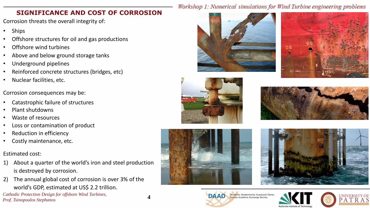
SIGNIFICANCE AND COST OF CORROSION
Corrosion threats the overall integrity of:
• Ships
• Offshore structures for oil and gas productions
• Offshore wind turbines
• Above and below ground storage tanks
• Underground pipelines
• Reinforced concrete structures (bridges, etc)
• Nuclear facilities, etc.
Corrosion consequences may be:
• Catastrophic failure of structures• Plant shutdowns
• Waste of resources
• Loss or contamination of product
• Reduction in efficiency
• Costly maintenance, etc.
Estimated cost:
1) About a quarter of the world’s iron and steel production
is destroyed by corrosion.
2) The annual global cost of corrosion is over 3% of the
world’s GDP, estimated at US$ 2.2 trillion.
Cathodic Protection Design for offshore Wind Turbines,
Prof. Tsinopoulos Stephanos5
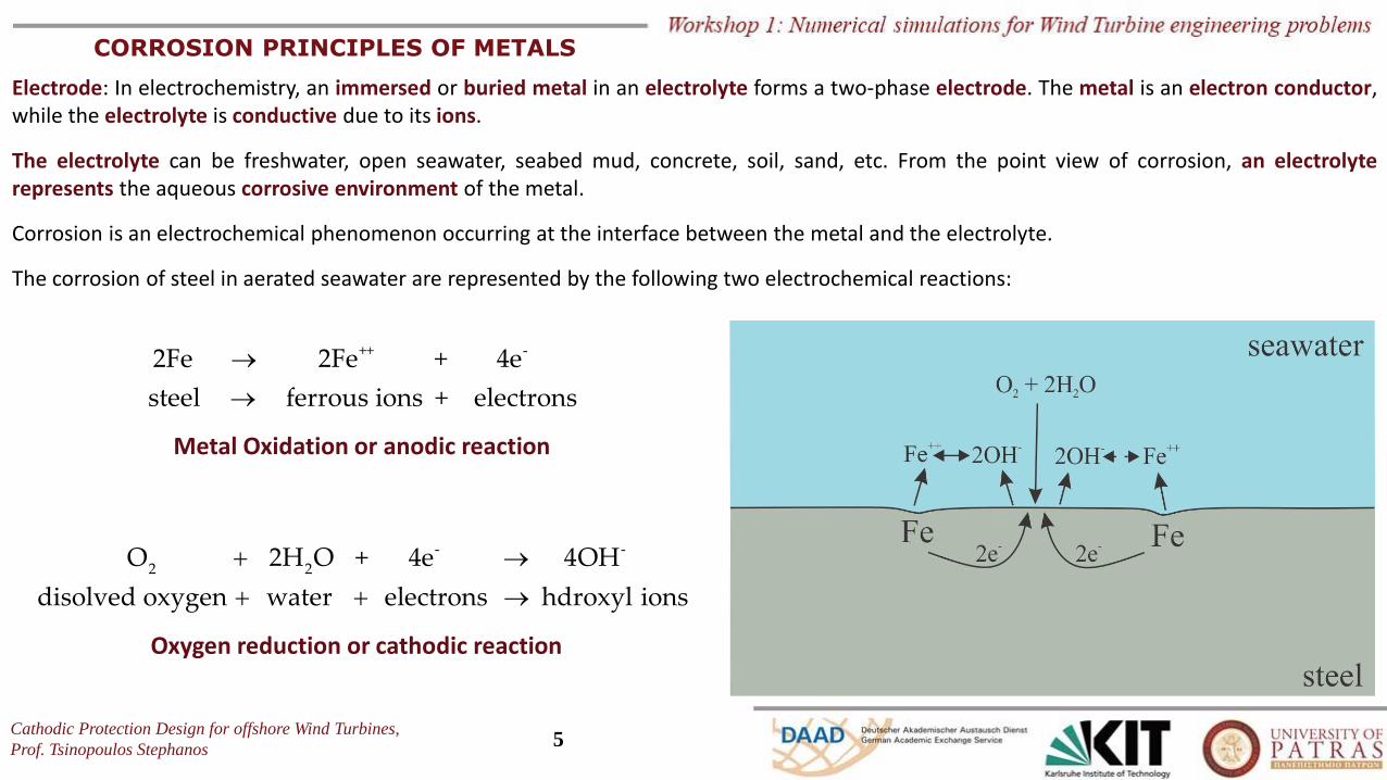
CORROSION PRINCIPLES OF METALS
Electrode: In electrochemistry, an immersed or buried metal in an electrolyte forms a two-phase electrode. The metal is an electron conductor,while the electrolyte is conductive due to its ions.
The electrolyte can be freshwater, open seawater, seabed mud, concrete, soil, sand, etc. From the point view of corrosion, an electrolyterepresents the aqueous corrosive environment of the metal.
Corrosion is an electrochemical phenomenon occurring at the interface between the metal and the electrolyte.
The corrosion of steel in aerated seawater are represented by the following two electrochemical reactions:
++ -2Fe 2Fe + 4e
steel ferrous ions + electrons
→
→
Metal Oxidation or anodic reaction
- -
2 2O 2H O + 4e 4OH
disolved oxygen water electrons hdroxyl ions
+ →
+ + →
Oxygen reduction or cathodic reaction
Cathodic Protection Design for offshore Wind Turbines,
Prof. Tsinopoulos Stephanos6
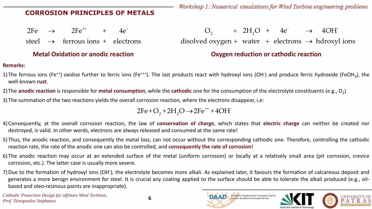
CORROSION PRINCIPLES OF METALS
Remarks:
1) The ferrous ions (Fe++) oxidize further to ferric ions (Fe+++). The last products react with hydroxyl ions (OH-) and produce ferric hydroxide (FeOH3), thewell-known rust.
2) The anodic reaction is responsible for metal consumption, while the cathodic one for the consumption of the electrolyte constituents (e.g., O2)
3) The summation of the two reactions yields the overall corrosion reaction, where the electrons disappear, i.e:
4) Consequently, at the overall corrosion reaction, the law of conservation of charge, which states that electric charge can neither be created nordestroyed, is valid. In other words, electrons are always released and consumed at the same rate!
5) Thus, the anodic reaction, and consequently the metal loss, can not occur without the corresponding cathodic one. Therefore, controlling the cathodicreaction rate, the rate of the anodic one can also be controlled, and consequently the rate of corrosion!
6) The anodic reaction may occur at an extended surface of the metal (uniform corrosion) or locally at a relatively small area (pit corrosion, crevicecorrosion, etc.). The latter case is usually more severe.
7) Due to the formation of hydroxyl ions (OH-), the electrolyte becomes more alkali. As explained later, it favours the formation of calcareous deposit andgenerates a more benign environment for steel. It is crucial any coating applied to the surface should be able to tolerate the alkali produced (e.g., oil-based and oleo-resinous paints are inappropriate).
++ -2Fe 2Fe + 4e
steel ferrous ions + electrons
→
→
Metal Oxidation or anodic reaction
- -
2 2O 2H O + 4e 4OH
disolved oxygen water electrons hdroxyl ions
+ →
+ + →
Oxygen reduction or cathodic reaction
++ -
2 22Fe+ O + 2H O 2Fe + 4OH→
Cathodic Protection Design for offshore Wind Turbines,
Prof. Tsinopoulos Stephanos7
CORROSION PRINCIPLES OF METALS
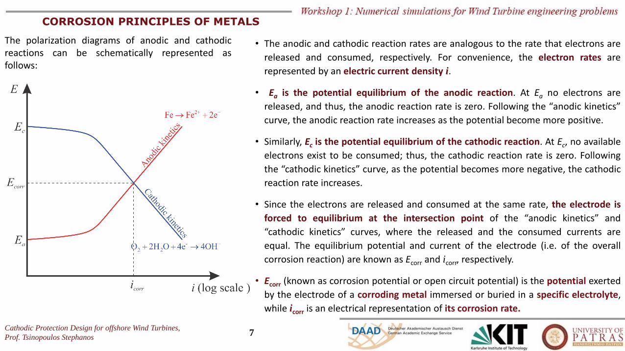
The polarization diagrams of anodic and cathodicreactions can be schematically represented asfollows:
• The anodic and cathodic reaction rates are analogous to the rate that electrons are
released and consumed, respectively. For convenience, the electron rates are
represented by an electric current density i.
• Ea is the potential equilibrium of the anodic reaction. At Ea no electrons are
released, and thus, the anodic reaction rate is zero. Following the “anodic kinetics”
curve, the anodic reaction rate increases as the potential become more positive.
• Similarly, Ec is the potential equilibrium of the cathodic reaction. At Ec, no available
electrons exist to be consumed; thus, the cathodic reaction rate is zero. Following
the “cathodic kinetics” curve, as the potential becomes more negative, the cathodic
reaction rate increases.
• Since the electrons are released and consumed at the same rate, the electrode is
forced to equilibrium at the intersection point of the “anodic kinetics” and
“cathodic kinetics” curves, where the released and the consumed currents are
equal. The equilibrium potential and current of the electrode (i.e. of the overall
corrosion reaction) are known as Ecorr and icorr, respectively.
• Ecorr (known as corrosion potential or open circuit potential) is the potential exerted
by the electrode of a corroding metal immersed or buried in a specific electrolyte,
while icorr is an electrical representation of its corrosion rate.
Cathodic Protection Design for offshore Wind Turbines,
Prof. Tsinopoulos Stephanos8
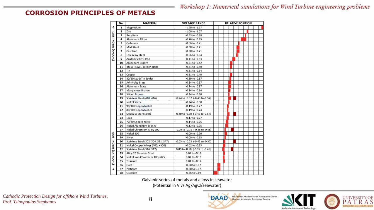
CORROSION PRINCIPLES OF METALS
Galvanic series of metals and alloys in seawater (Potential in V vs Ag/AgCl/seawater)
Cathodic Protection Design for offshore Wind Turbines,
Prof. Tsinopoulos Stephanos9
CORROSION PRINCIPLES OF METALS
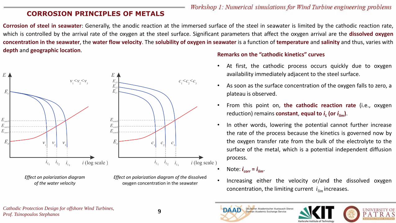
Corrosion of steel in seawater: Generally, the anodic reaction at the immersed surface of the steel in seawater is limited by the cathodic reaction rate,
which is controlled by the arrival rate of the oxygen at the steel surface. Significant parameters that affect the oxygen arrival are the dissolved oxygen
concentration in the seawater, the water flow velocity. The solubility of oxygen in seawater is a function of temperature and salinity and thus, varies with
depth and geographic location.
Effect on polarization diagramof the water velocity
Effect on polarization diagram of the dissolved oxygen concentration in the seawater
Remarks on the “cathodic kinetics” curves
• At first, the cathodic process occurs quickly due to oxygen
availability immediately adjacent to the steel surface.
• As soon as the surface concentration of the oxygen falls to zero, a
plateau is observed.
• From this point on, the cathodic reaction rate (i.e., oxygen
reduction) remains constant, equal to iL (or ilim).
• In other words, lowering the potential cannot further increase
the rate of the process because the kinetics is governed now by
the oxygen transfer rate from the bulk of the electrolyte to the
surface of the metal, which is a potential independent diffusion
process.
• Note: icorr = ilim.
• Increasing either the velocity or/and the dissolved oxygen
concentration, the limiting current ilim increases.
Cathodic Protection Design for offshore Wind Turbines,
Prof. Tsinopoulos Stephanos10
PRINCIPLES OF CATHODIC PROTECION
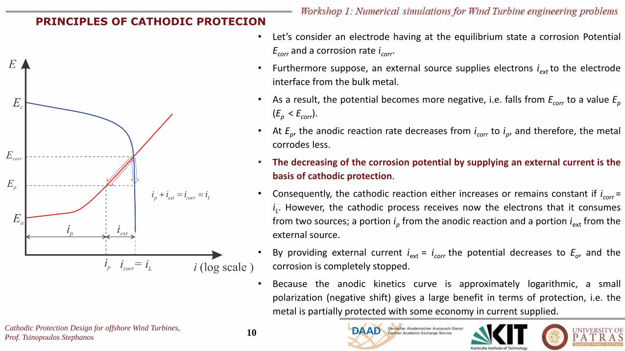
• Let’s consider an electrode having at the equilibrium state a corrosion Potential
Ecorr and a corrosion rate icorr.
• Furthermore suppose, an external source supplies electrons iext to the electrode
interface from the bulk metal.
• As a result, the potential becomes more negative, i.e. falls from Ecorr to a value Ep
(Ep < Ecorr).
• At Ep, the anodic reaction rate decreases from icorr to ip, and therefore, the metal
corrodes less.
• The decreasing of the corrosion potential by supplying an external current is the
basis of cathodic protection.
• Consequently, the cathodic reaction either increases or remains constant if icorr =
iL. However, the cathodic process receives now the electrons that it consumes
from two sources; a portion ip from the anodic reaction and a portion iext from the
external source.
• By providing external current iext = icorr the potential decreases to Ea, and the
corrosion is completely stopped.
• Because the anodic kinetics curve is approximately logarithmic, a small
polarization (negative shift) gives a large benefit in terms of protection, i.e. the
metal is partially protected with some economy in current supplied.
Cathodic Protection Design for offshore Wind Turbines,
Prof. Tsinopoulos Stephanos11
CATHODIC PROTECION METHODS
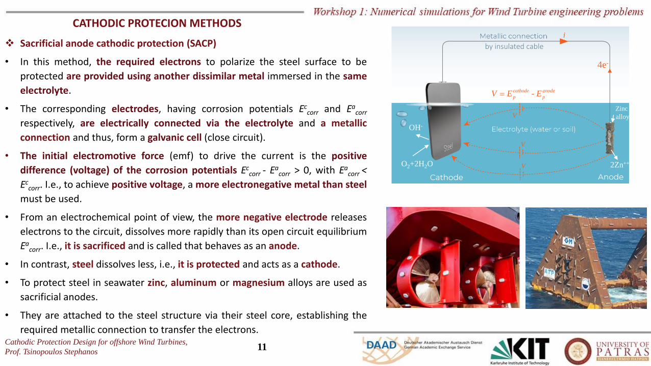
❖ Sacrificial anode cathodic protection (SACP)
• In this method, the required electrons to polarize the steel surface to be
protected are provided using another dissimilar metal immersed in the same
electrolyte.
• The corresponding electrodes, having corrosion potentials Eccorr and Ea
corr
respectively, are electrically connected via the electrolyte and a metallic
connection and thus, form a galvanic cell (close circuit).
• The initial electromotive force (emf) to drive the current is the positive
difference (voltage) of the corrosion potentials Eccorr - Ea
corr > 0, with Eacorr <
Eccorr. I.e., to achieve positive voltage, a more electronegative metal than steel
must be used.
• From an electrochemical point of view, the more negative electrode releases
electrons to the circuit, dissolves more rapidly than its open circuit equilibrium
Eacorr. I.e., it is sacrificed and is called that behaves as an anode.
• In contrast, steel dissolves less, i.e., it is protected and acts as a cathode.
• To protect steel in seawater zinc, aluminum or magnesium alloys are used as
sacrificial anodes.
• They are attached to the steel structure via their steel core, establishing the
required metallic connection to transfer the electrons.
O2+2H2O
OH-
2Zn++
4e-
V
V
-cathode anode
p pV E E=
V
Zinc
alloy
by insulated cable
Cathodic Protection Design for offshore Wind Turbines,
Prof. Tsinopoulos Stephanos12
CATHODIC PROTECION METHODS
❖ Sacrificial anode cathodic protection (SACP)
Zinc
alloy
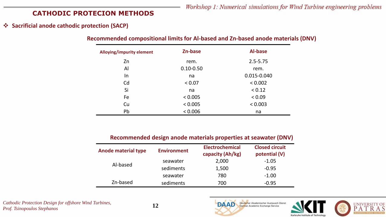
Alloying/impurity element Zn-base Al-base
Zn rem. 2.5-5.75
Al 0.10-0.50 rem.
In na 0.015-0.040
Cd < 0.07 < 0.002
Si na < 0.12
Fe < 0.005 < 0.09
Cu < 0.005 < 0.003
Pb < 0.006 na
Anode material type EnvironmentElectrochemical capacity (Ah/kg)
Closed circuit potential (V)
Al-basedseawater 2,000 -1.05
sediments 1,500 -0.95
seawater 780 -1.00Zn-based sediments 700 -0.95
Recommended compositional limits for Al-based and Zn-based anode materials (DNV)
Recommended design anode materials properties at seawater (DNV)
Cathodic Protection Design for offshore Wind Turbines,
Prof. Tsinopoulos Stephanos13
CATHODIC PROTECION METHODS
❖ Sacrificial anode cathodic protection (SACP)
Zinc
alloy
Platform anodes Pipeline bracelet anodes Pier & piling anodes
Sacrificial anodes are available in different weights, dimensions, different inserts and mounting options
Hull anodes
Other type of anodes
Cathodic Protection Design for offshore Wind Turbines,
Prof. Tsinopoulos Stephanos14
CATHODIC PROTECION METHODS
❖ Impressed Current cathodic protection (ICCP)
• In this method, the driving voltage to polarize the steel surface to be protected is a direct current
(DC) external power source. Usually, the DC is produced by an altering current transformer
rectifier.
• Consequently, there is no need for anodes made by more electronegative metals than steel to be
used. Using noble metals for anodes is a significant advantage because these materials do not
dissolve on anodic polarization and practically remain unconsumed (inert anodes). The anodic
reactions which provide the required electrons involve decomposition of the electrolyte
compounds, such as:
• Inert anodes are usually made of graphite, thin coatings of platinum, etc.
• The metallic connection must be performed in the right direction, i.e., the positive pole of the
external power is connected to the anode, while its negative pole is attached to the structure.
• In an ICCP system, since the driving voltage can be significantly larger than in an SACP one, a few
anodes are enough to protect large uncoated surfaces, even if they are embedded in high
resistivity electrolytes.
• A dielectric shield should usually be applied in the vicinity of the anodes to prevent extremelyhigh current densities and avoid undesired over-polarization (will be explained later). Dielectricshield materials include epoxy materials, coal-tar epoxy resins, polyurethane coatings, rubbercoatings, etc.
• Furthermore, potential sensors (reference electrodes) are used, adjusting the delivered current
automatically to achieve the desired predefined protection potential.
+→ + + → +- - -
2 2 22H O O 4H 4e and 2Cl Cl 2e O2+2H2O
OH-
6e-
Cl22Cl-
O2+4H+
2H2O
Metallic connectionby insulated cable
Cathodic Protection Design for offshore Wind Turbines,
Prof. Tsinopoulos Stephanos15
CATHODIC PROTECION METHODS
❖ Impressed Current cathodic protection (ICCP)
Anode for ICCP systems are available in different shape and mounting options, delivering current up to 350A.
Linear loop anodesLinear anodes
Elliptical anodes
Disc anodes
Cathodic Protection Design for offshore Wind Turbines,
Prof. Tsinopoulos Stephanos16
Sacrificial Anode
Cathodic Protection
(SACP)
Advantages Disadvantages
No need for external power sourceCurrent output is limited. It has limited driving potential
Less complex installation
Uniform distribution of currentPoorly coated structures need more anodes
Minimum maintenance
Minimum cathodic interference The system is ineffective in high resistivity environments
ImpressedCurrent
Cathodic Protection
(ICCP)
Advantages Disadvantages
The system is adjustable Overprotection leads to coating damage and hydrogen embrittlementHigh current can be impressed with a single ground bed
Single installation can protect larger metallic surfaceThe system is affected by interference problems
Uncoated and poorly coated structures can be effectively protected
Voltage and current can be varied to meet changing conditions over time
External power is necessary, thus the system is vulnerable to power failure
CATHODIC PROTECION METHODS
❖ SACP vs. ICCP systems
Cathodic Protection Design for offshore Wind Turbines,
Prof. Tsinopoulos Stephanos17
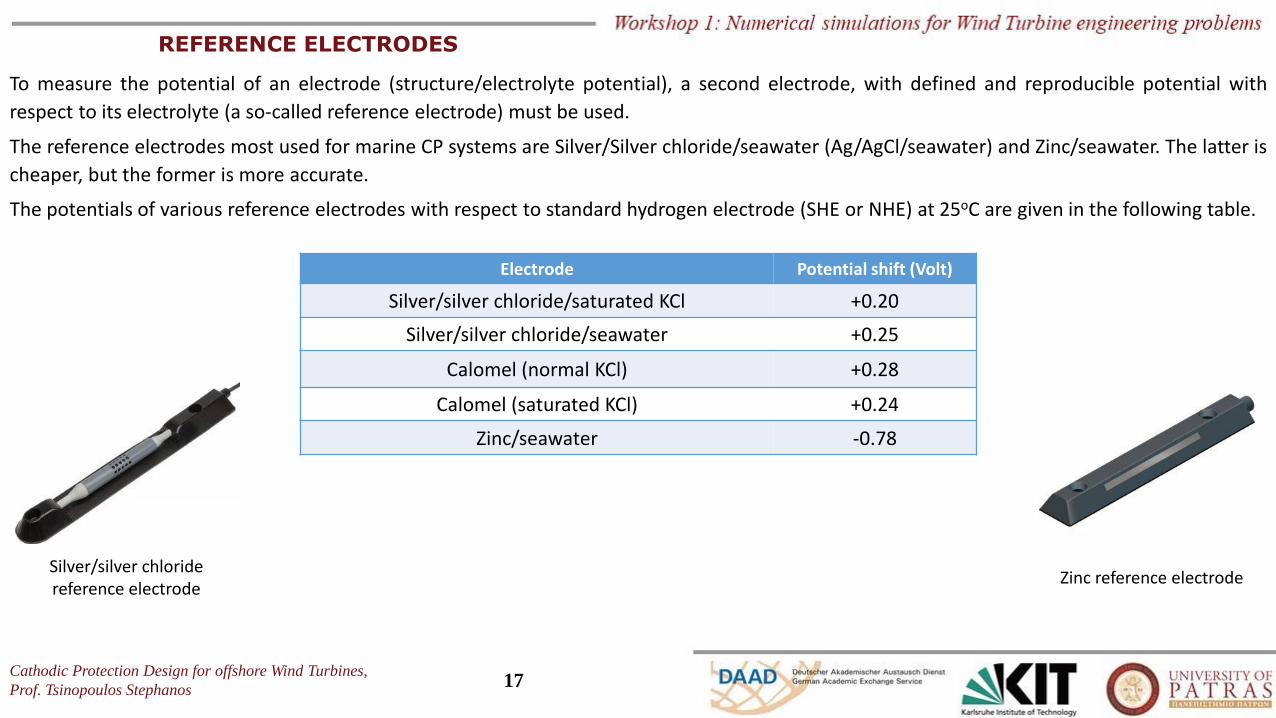
REFERENCE ELECTRODES
To measure the potential of an electrode (structure/electrolyte potential), a second electrode, with defined and reproducible potential with
respect to its electrolyte (a so-called reference electrode) must be used.
The reference electrodes most used for marine CP systems are Silver/Silver chloride/seawater (Ag/AgCl/seawater) and Zinc/seawater. The latter is
cheaper, but the former is more accurate.
The potentials of various reference electrodes with respect to standard hydrogen electrode (SHE or NHE) at 25oC are given in the following table.
Electrode Potential shift (Volt)
Silver/silver chloride/saturated KCl +0.20
Silver/silver chloride/seawater +0.25
Calomel (normal KCl) +0.28
Calomel (saturated KCl) +0.24
Zinc/seawater -0.78
Silver/silver chloride reference electrode
Zinc reference electrode
Cathodic Protection Design for offshore Wind Turbines,
Prof. Tsinopoulos Stephanos18
PROTECTION CRITERIA
❖ Steel
o Minimum negative potential level
As already mentioned, the corrosion is completely stopped at a steel surface, decreasing the potential from Ecorr to Ea by providing external
current. However, to achieve this, an excessive amount of current is required, which is not practical from an economic point of view. Experiments
and experience have shown that when carbon steel in aerated sea water is polarized up to -0.80V (Ag/AgCl/sw RE), the corrosion rate decreases
to an acceptable level. Consequently, this is the general the minimum negative potential level used for the cathodic protection of carbon steel in
aerated sea water.
In case of steel in anaerobic conditions (e.g. some seabed muds), due to the possibility of microbially-assisted corrosion, the accepted minimum
negative potential level is -0.90V (Ag/AgCl/sw RE).
o Maximum negative potential level – Over-protection
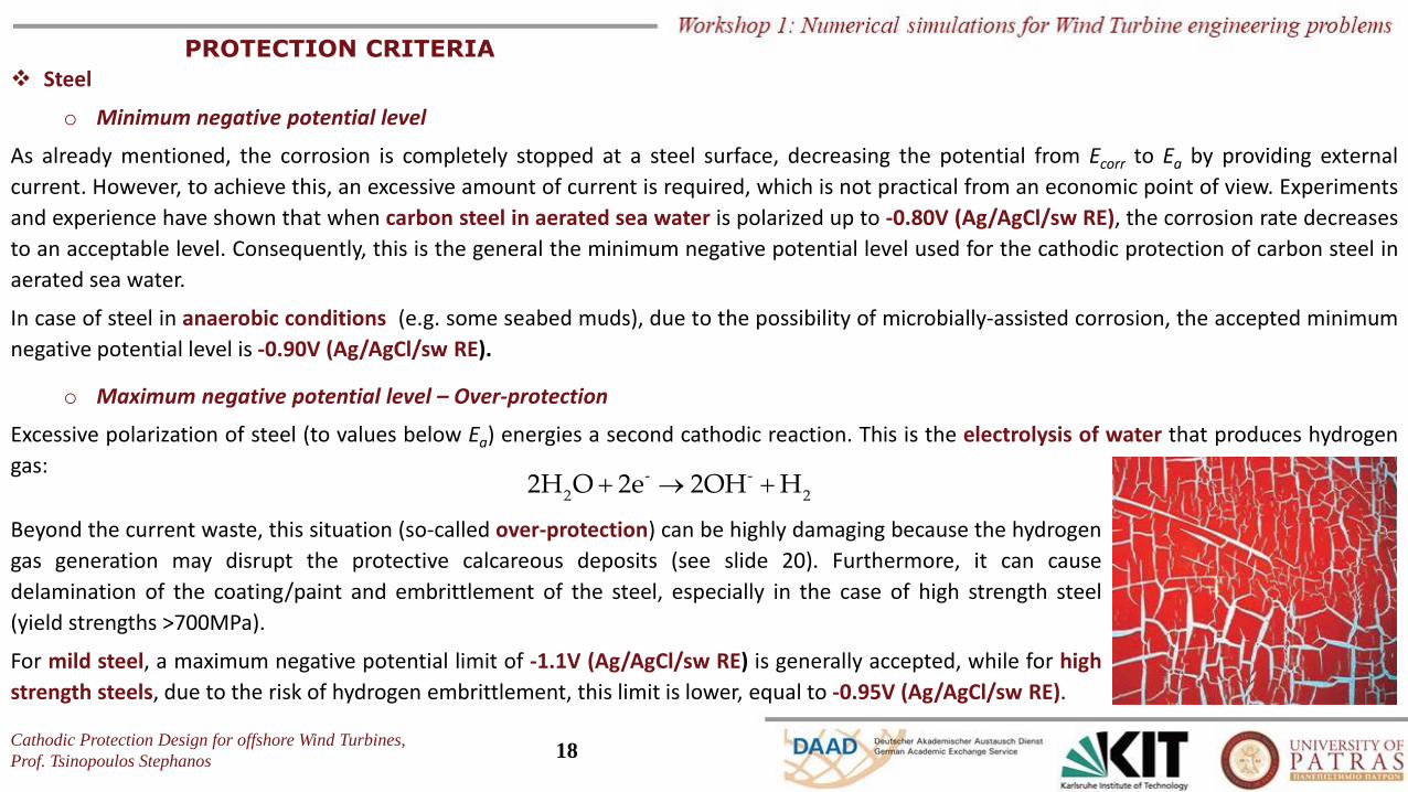
Excessive polarization of steel (to values below Ea) energies a second cathodic reaction. This is the electrolysis of water that produces hydrogen
gas:+ → +- -
2 22H O 2e 2OH H
Beyond the current waste, this situation (so-called over-protection) can be highly damaging because the hydrogen
gas generation may disrupt the protective calcareous deposits (see slide 20). Furthermore, it can cause
delamination of the coating/paint and embrittlement of the steel, especially in the case of high strength steel
(yield strengths >700MPa).
For mild steel, a maximum negative potential limit of -1.1V (Ag/AgCl/sw RE) is generally accepted, while for high
strength steels, due to the risk of hydrogen embrittlement, this limit is lower, equal to -0.95V (Ag/AgCl/sw RE).
Cathodic Protection Design for offshore Wind Turbines,
Prof. Tsinopoulos Stephanos19
PROTECTION CRITERIA
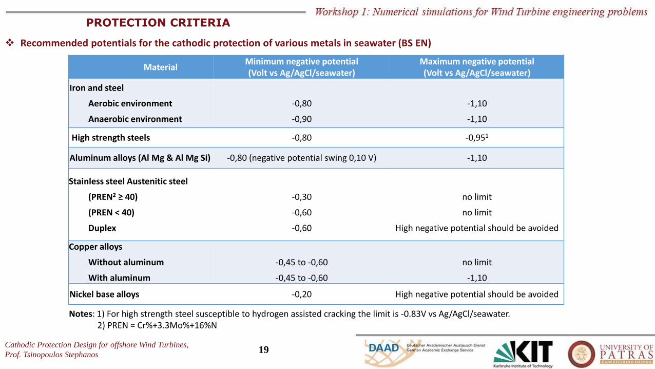
❖ Recommended potentials for the cathodic protection of various metals in seawater (BS EN)
MaterialMinimum negative potential (Volt vs Ag/AgCl/seawater)
Maximum negative potential (Volt vs Ag/AgCl/seawater)
Iron and steel
Aerobic environment
Anaerobic environment
-0,80
-0,90
-1,10
-1,10
High strength steels -0,80 -0,951
Aluminum alloys (Al Mg & Al Mg Si) -0,80 (negative potential swing 0,10 V) -1,10
Stainless steel Austenitic steel
(PREN2 ≥ 40)
(PREN < 40)
Duplex
-0,30
-0,60
-0,60
no limit
no limit
High negative potential should be avoided
Copper alloys
Without aluminum
With aluminum
-0,45 to -0,60
-0,45 to -0,60
no limit
-1,10
Nickel base alloys -0,20 High negative potential should be avoided
Notes: 1) For high strength steel susceptible to hydrogen assisted cracking the limit is -0.83V vs Ag/AgCl/seawater.2) PREN = Cr%+3.3Mo%+16%N
Cathodic Protection Design for offshore Wind Turbines,
Prof. Tsinopoulos Stephanos20
ENVIROMENTAL FACTORS ON CURRENT DEMAND
The current required to achieve the recommended potentials for cathodic protection depends on several environmental factors.
o Dissolved oxygen
As already mentioned, (Slide 9), the dissolved oxygen in the electrolyte is correlated with the corrosion rate. Consequently, the required current
density for protection is proportional to the rate of dissolved oxygen that diffuses to the steel surface. The dissolved oxygen concentration in
seawater decreases as water depth, temperature and salinity increase.
Furthermore, sea currents and waves increase the transfer rate of the dissolved oxygen to the steel surface and, thus, the current density
requirement for cathodic protection.
o Calcareous deposits
When the cathodic protection is applied, the anodic reaction rate is lower, but the cathodic one remains energized. Thus, an excess amount of
hydroxyl ions is produced at the steel surface. This high concentration of hydroxyl ions triggers a few other reactions, the products of which are
calcium carbonate (CaCO3) and magnesium hydroxide (Mg(OH)2).
Both products are insoluble and form a protective film at the steel surface, known as calcareous deposit, which acts as a paint coating.
Thus, after a high initial temporary current density requirement for a rapid cathodic polarization to form a high protective the calcareous film, a
significant decrease in demand is observed.
Note that mechanical damage (e.g., during a storm) or excessive hydrogen generation may damage the film. Thus, the cathodic protection
system at any time, even at the end of its design life, must be capable of delivering increased current to depolarize the steel surface and reform
the calcareous deposit. The above-mentioned current demands, the first for the initial polarization, the second since the calcareous deposit is
formed, and the third for the repolarization after a damage of the film, are referred to standards and recommendations as initial, maintenance or
mean and final, respectively.
Cathodic Protection Design for offshore Wind Turbines,
Prof. Tsinopoulos Stephanos21
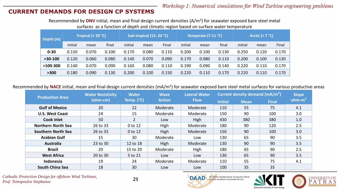
CURRENT DEMANDS FOR DESIGN CP SYSTEMS
Depth (m)Tropical (> 20 °C) Sub-tropical (12- 20 °C) Temperate (7-11 °C) Arctic (< 7 °C)
initial mean final initial mean Final initial mean final initial mean Final
0-30 0.150 0.070 0.100 0.170 0.080 0.110 0.200 0.100 0.130 0.250 0.120 0.170
>30-100 0.120 0.060 0.080 0.140 0.070 0.090 0.170 0.080 0.110 0.200 0.100 0.130
>100-300 0.140 0.070 0.090 0.160 0.080 0.110 0.190 0.090 0.140 0.220 0.110 0.170
>300 0.180 0.090 0.130 0.200 0.100 0.150 0.220 0.110 0.170 0.220 0.110 0.170
Recommended by DNV initial, mean and final design current densities (A/m2) for seawater exposed bare steel metal surfaces as a function of depth and climatic region based on surface water temperature
Production AreaWater Resistivity
(ohm-cm)Water
Temp. (°C)WaveAction
Lateral WaterFlow
Current density demand (mA/m2) Slopeohm-m2
Initial Mean Final
Gulf of Mexico 20 22 Moderate Moderate 110 55 75 4.1
U.S. West Coast 24 15 Moderate Moderate 150 90 100 3.0
Cook Inlet 50 2 Low High 430 380 380 1.0
Northern North Sea 26 to 33 0 to 12 High Moderate 180 90 120 2.5
Southern North Sea 26 to 33 0 to 12 High Moderate 150 90 100 3.0
Arabian Gulf 15 30 Moderate Low 130 65 90 3.5
Australia 23 to 30 12 to 18 High Moderate 130 90 90 3.5
Brazil 20 15 to 20 Moderate High 180 65 90 2.5
West Africa 20 to 30 5 to 21 Low Low 130 65 90 3.5
Indonesia 19 24 Moderate Moderate 110 55 75 4.1
South China Sea 18 30 Low Low 100 35 35
Recommended by NACE initial, mean and final design current densities (mA/m2) for seawater exposed bare steel metal surfaces for various productive areas
Cathodic Protection Design for offshore Wind Turbines,
Prof. Tsinopoulos Stephanos22
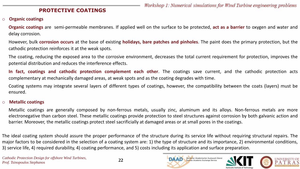
PROTECTIVE COATINGS
o Organic coatings
Organic coatings are semi-permeable membranes. If applied well on the surface to be protected, act as a barrier to oxygen and water and
delay corrosion.
However, bulk corrosion occurs at the base of existing holidays, bare patches and pinholes. The paint does the primary protection, but the
cathodic protection reinforces it at the weak spots.
The coating, reducing the exposed area to the corrosive environment, decreases the total current requirement for protection, improves the
potential distribution and reduces the interference effects.
In fact, coatings and cathodic protection complement each other. The coatings save current, and the cathodic protection acts
complementary at mechanically damaged areas, at weak spots and as the coating degrades with time.
Coating systems may integrate several layers of different types of coatings, however, the compatibility between the coats (layers) must beensured.
o Metallic coatings
Metallic coatings are generally composed by non-ferrous metals, usually zinc, aluminum and its alloys. Non-ferrous metals are moreelectronegative than carbon steel. These metallic coatings provide protection to steel structures against corrosion by both galvanic action andbarrier. Moreover, the metallic coatings protect steel sacrificially at damaged areas or at small pores in the coatings.
The ideal coating system should assure the proper performance of the structure during its service life without requiring structural repairs. Themajor factors to be considered in the selection of a coating system are: 1) the type of structure and its importance, 2) environmental conditions,3) service life, 4) required durability, 4) coating performance, and 5) costs including its application and surface preparation.
Cathodic Protection Design for offshore Wind Turbines,
Prof. Tsinopoulos Stephanos23
PROTECTIVE COATINGS
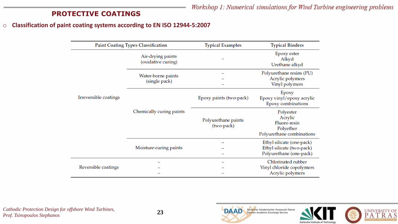
o Classification of paint coating systems according to EN ISO 12944-5:2007
Cathodic Protection Design for offshore Wind Turbines,
Prof. Tsinopoulos Stephanos24
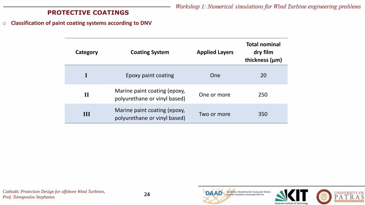
PROTECTIVE COATINGS
o Classification of paint coating systems according to DNV
Category Coating System Applied Layers
Total nominal
dry film
thickness (μm)
I Epoxy paint coating One 20
IIMarine paint coating (epoxy,
polyurethane or vinyl based)One or more 250
IIIMarine paint coating (epoxy,
polyurethane or vinyl based)Two or more 350
Cathodic Protection Design for offshore Wind Turbines,
Prof. Tsinopoulos Stephanos25
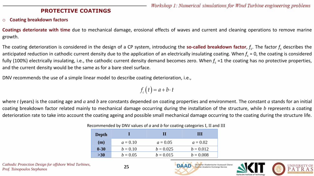
PROTECTIVE COATINGS
o Coating breakdown factors
Coatings deteriorate with time due to mechanical damage, erosional effects of waves and current and cleaning operations to remove marine
growth.
The coating deterioration is considered in the design of a CP system, introducing the so-called breakdown factor, fc. The factor fc describes the
anticipated reduction in cathodic current density due to the application of an electrically insulating coating. When fc = 0, the coating is considered
fully (100%) electrically insulating, i.e., the cathodic current density demand becomes zero. When fc =1 the coating has no protective properties,
and the current density would be the same as for a bare steel surface.
DNV recommends the use of a simple linear model to describe coating deterioration, i.e.,
( ) = + cf t a b t
where t (years) is the coating age and a and b are constants depended on coating properties and environment. The constant a stands for an initial
coating breakdown factor related mainly to mechanical damage occurring during the installation of the structure, while b represents a coating
deterioration rate to take into account the coating ageing and possible small mechanical damage occurring to the coating during the structure life.
Depth
(m)
I II III
a = 0.10 a = 0.05 a = 0.02
0-30 b = 0.10 b = 0.025 b = 0.012
>30 b = 0.05 b = 0.015 b = 0.008
Recommended by DNV values of a and b for coating categories I, II and III
Cathodic Protection Design for offshore Wind Turbines,
Prof. Tsinopoulos Stephanos26
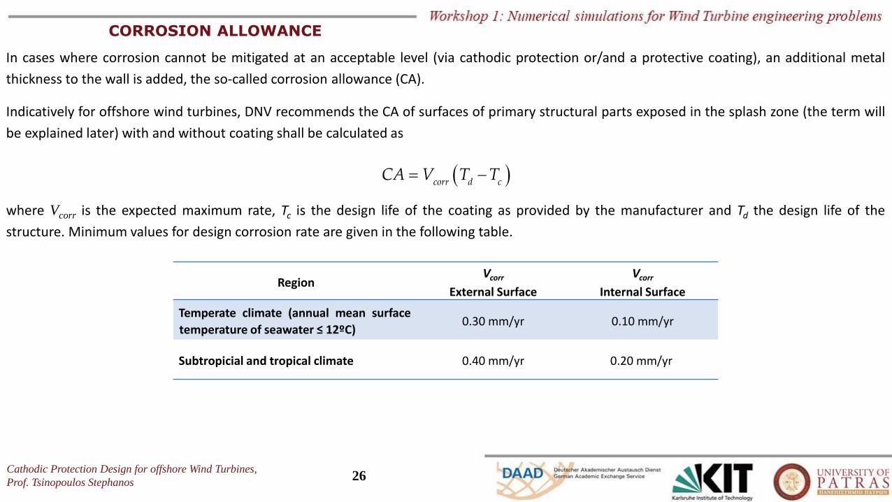
CORROSION ALLOWANCE
In cases where corrosion cannot be mitigated at an acceptable level (via cathodic protection or/and a protective coating), an additional metal
thickness to the wall is added, the so-called corrosion allowance (CA).
Indicatively for offshore wind turbines, DNV recommends the CA of surfaces of primary structural parts exposed in the splash zone (the term will
be explained later) with and without coating shall be calculated as
( )= −corr d c
CA V T T
where Vcorr is the expected maximum rate, Tc is the design life of the coating as provided by the manufacturer and Td the design life of the
structure. Minimum values for design corrosion rate are given in the following table.
RegionVcorr
External Surface
VcorrInternal Surface
Temperate climate (annual mean surface
temperature of seawater ≤ 12ºC)0.30 mm/yr 0.10 mm/yr
Subtropicial and tropical climate 0.40 mm/yr 0.20 mm/yr
Cathodic Protection Design for offshore Wind Turbines,
Prof. Tsinopoulos Stephanos27
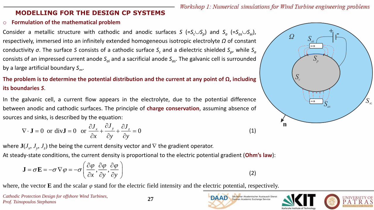
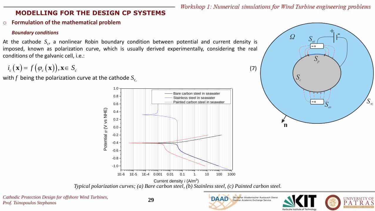
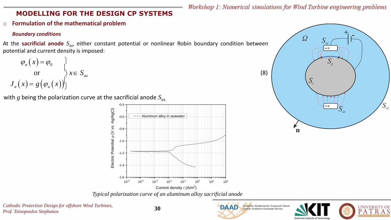
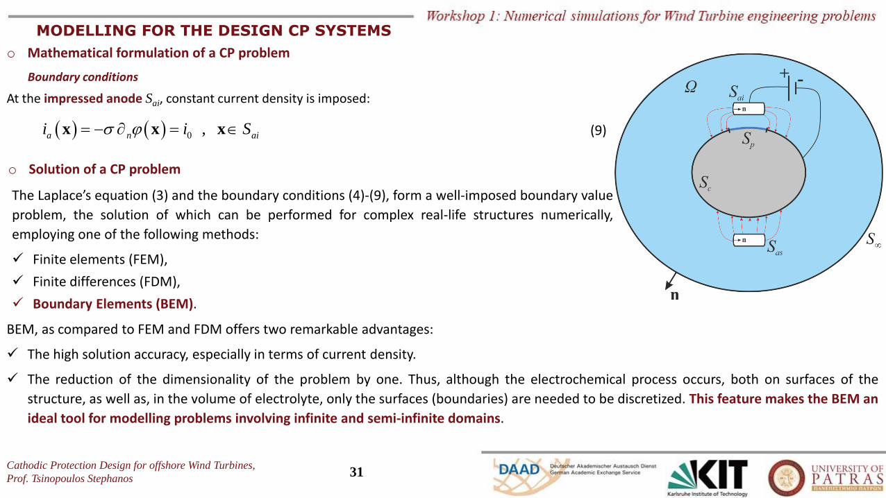
MODELLING FOR THE DESIGN CP SYSTEMS
o Formulation of the mathematical problem
Consider a metallic structure with cathodic and anodic surfaces S (=ScSp) and Sa (=SasSai),
respectively, immersed into an infinitely extended homogeneous isotropic electrolyte Ω of constant
conductivity σ. The surface S consists of a cathodic surface Sc and a dielectric shielded Sp, while Sa
consists of an impressed current anode Sai and a sacrificial anode Sas. The galvanic cell is surrounded
by a large artificial boundary S∞.
The problem is to determine the potential distribution and the current at any point of Ω, including
its boundaries S.
In the galvanic cell, a current flow appears in the electrolyte, due to the potential difference
between anodic and cathodic surfaces. The principle of charge conservation, assuming absence of
sources and sinks, is described by the equation:
0 or div 0 or 0yx z
JJ J
x y y
= = + + =
J J
where J(Jx, Jy, Jz) the being the current density vector and the gradient operator.
(1)
, ,x y y
= = − = −
J E
At steady-state conditions, the current density is proportional to the electric potential gradient (Ohm’s law):
where, the vector E and the scalar φ stand for the electric field intensity and the electric potential, respectively.
(2)
Cathodic Protection Design for offshore Wind Turbines,
Prof. Tsinopoulos Stephanos28
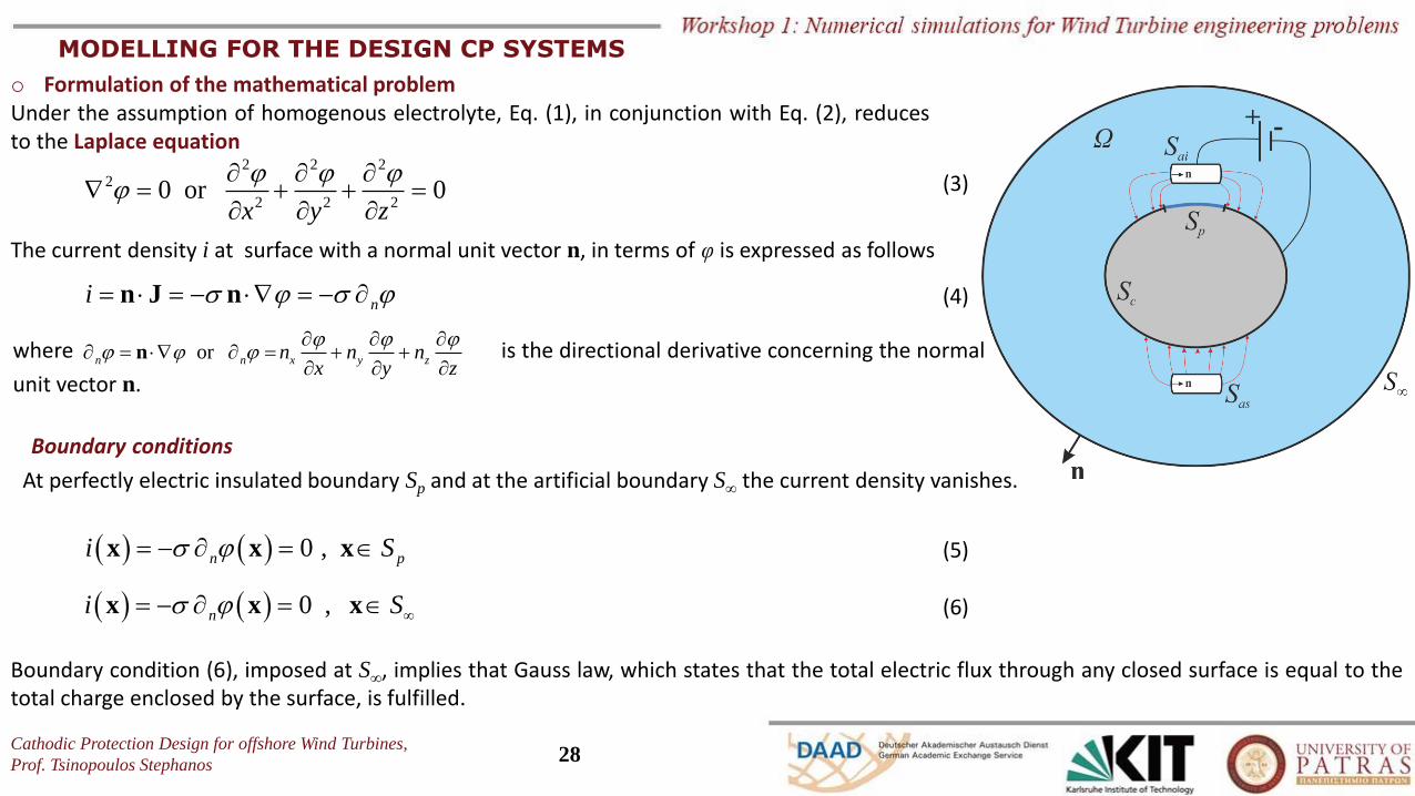
Under the assumption of homogenous electrolyte, Eq. (1), in conjunction with Eq. (2), reducesto the Laplace equation
2 2 22
2 2 20 or 0
x y z
= + + =
(3)
The current density i at surface with a normal unit vector n, in terms of φ is expressed as follows
(4)ni = = − = − n J n
orn n x y zn n nx y z
= = + +
nwhere is the directional derivative concerning the normal
unit vector n.
At perfectly electric insulated boundary Sp and at the artificial boundary S∞ the current density vanishes.
o Formulation of the mathematical problem
Boundary conditions
( ) ( ) 0 ,ni S = − = x x x
( ) ( ) 0 ,n pi S = − = x x x (5)
(6)
Boundary condition (6), imposed at S∞, implies that Gauss law, which states that the total electric flux through any closed surface is equal to thetotal charge enclosed by the surface, is fulfilled.
MODELLING FOR THE DESIGN CP SYSTEMS
Cathodic Protection Design for offshore Wind Turbines,
Prof. Tsinopoulos Stephanos29
o Formulation of the mathematical problem
Boundary conditions
At the cathode Sc, a nonlinear Robin boundary condition between potential and current density isimposed, known as polarization curve, which is usually derived experimentally, considering the realconditions of the galvanic cell, i.e.:
(7)( ) ( )( ) ,c c ci f S= x x x
with f being the polarization curve at the cathode Sc.
1E-6 1E-5 1E-4 0.001 0.01 0.1 1 10 100 1000
-1.0
-0.8
-0.6
-0.4
-0.2
0.0
0.2
0.4
0.6
0.8
1.0
Po
ten
tial φ (
V v
s N
HE
)
Current density i (A/m2)
Bare carbon steel in seawater
Stainless steel in seawater
Painted carbon steel in seawater
Typical polarization curves; (a) Bare carbon steel, (b) Stainless steel, (c) Painted carbon steel.
MODELLING FOR THE DESIGN CP SYSTEMS
Cathodic Protection Design for offshore Wind Turbines,
Prof. Tsinopoulos Stephanos30
o Formulation of the mathematical problem
Boundary conditions
At the sacrificial anode Sas, either constant potential or nonlinear Robin boundary condition betweenpotential and current density is imposed:
with g being the polarization curve at the sacrificial anode Sas.
Typical polarization curve of an aluminum alloy sacrificial anode
(8)
( )
( ) ( )( )
0
or
a
as
a a
x
x S
J x g x
=
=
10-5 10-4 10-3 10-2 10-1 100 101 102
-1.6
-1.4
-1.2
-1.0
-0.8
-0.6
-0.4
Aluminum alloy in seawater
Ele
ctr
ic P
ote
ntial
(V
vs. A
g/A
gC
l)
Current density i (A/m2)
MODELLING FOR THE DESIGN CP SYSTEMS
Cathodic Protection Design for offshore Wind Turbines,
Prof. Tsinopoulos Stephanos31
o Mathematical formulation of a CP problem
Boundary conditions
At the impressed anode Sai, constant current density is imposed:
( ) ( ) 0 ,a n aii i S = − = x x x (9)
o Solution of a CP problem
The Laplace’s equation (3) and the boundary conditions (4)-(9), form a well-imposed boundary value
problem, the solution of which can be performed for complex real-life structures numerically,
employing one of the following methods:
✓ Finite elements (FEM),
✓ Finite differences (FDM),
✓ Boundary Elements (BEM).
BEM, as compared to FEM and FDM offers two remarkable advantages:
✓ The high solution accuracy, especially in terms of current density.
✓ The reduction of the dimensionality of the problem by one. Thus, although the electrochemical process occurs, both on surfaces of the
structure, as well as, in the volume of electrolyte, only the surfaces (boundaries) are needed to be discretized. This feature makes the BEM an
ideal tool for modelling problems involving infinite and semi-infinite domains.
MODELLING FOR THE DESIGN CP SYSTEMS
Cathodic Protection Design for offshore Wind Turbines,
Prof. Tsinopoulos Stephanos32
Part 2:
Cathodic Protection for wind Turbines
Cathodic Protection Design for offshore Wind Turbines,
Prof. Tsinopoulos Stephanos33
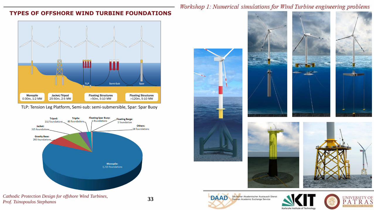
TLP: Tension Leg Platform, Semi-sub: semi-submersible, Spar: Spar Buoy
TYPES OF OFFSHORE WIND TURBINE FOUNDATIONS
Cathodic Protection Design for offshore Wind Turbines,
Prof. Tsinopoulos Stephanos34
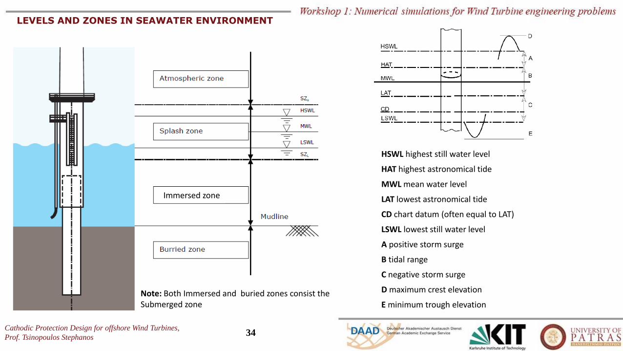
LEVELS AND ZONES IN SEAWATER ENVIRONMENT
HSWL highest still water level
HAT highest astronomical tide
MWL mean water level
LAT lowest astronomical tide
CD chart datum (often equal to LAT)
LSWL lowest still water level
A positive storm surge
B tidal range
C negative storm surge
D maximum crest elevation
E minimum trough elevation
Immersed zone
Note: Both Immersed and buried zones consist the Submerged zone
Cathodic Protection Design for offshore Wind Turbines,
Prof. Tsinopoulos Stephanos35
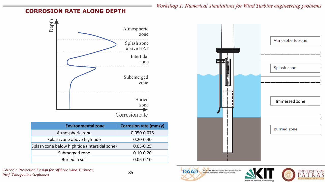
CORROSION RATE ALONG DEPTH
Environmental zone Corrosion rate (mm/y)
Atmospheric zone 0.050-0.075
Splash zone above high tide 0.20-0.40
Splash zone below high tide (Intertidal zone) 0.05-0.25
Submerged zone 0.10-0.20
Buried in soil 0.06-0.10
Immersed zone
Cathodic Protection Design for offshore Wind Turbines,
Prof. Tsinopoulos Stephanos36
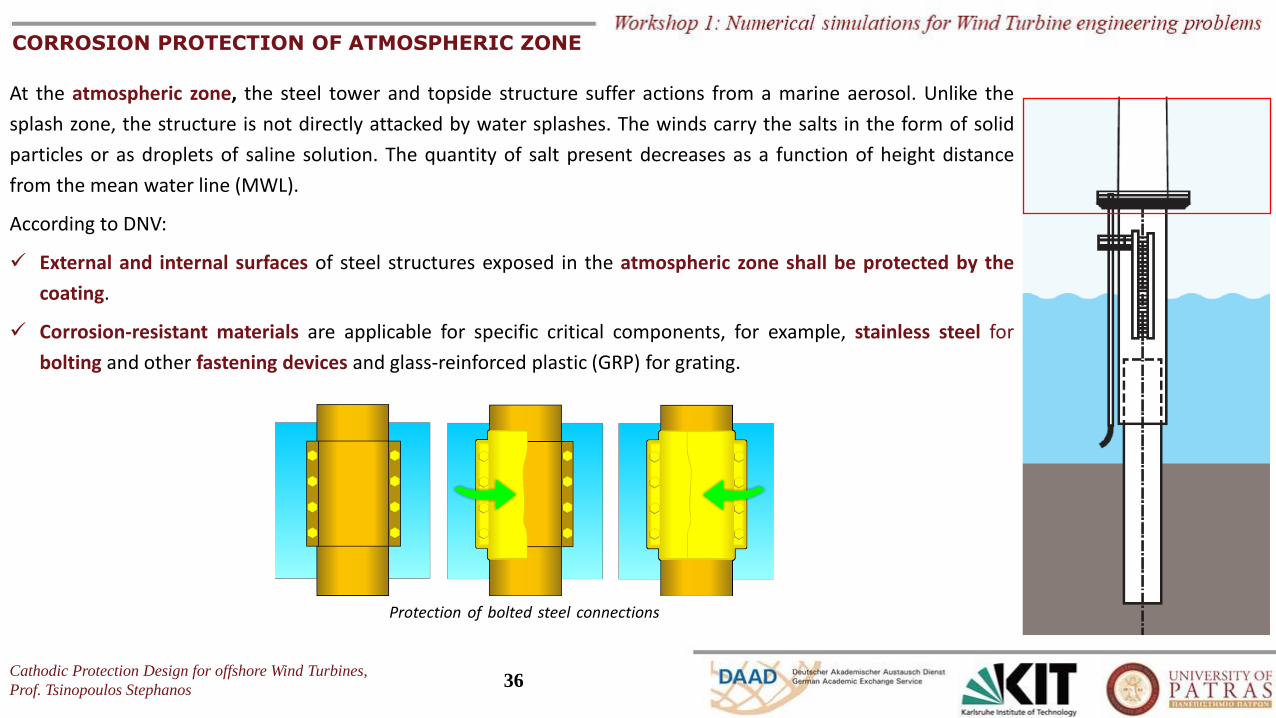
CORROSION PROTECTION OF ATMOSPHERIC ZONE
At the atmospheric zone, the steel tower and topside structure suffer actions from a marine aerosol. Unlike the
splash zone, the structure is not directly attacked by water splashes. The winds carry the salts in the form of solid
particles or as droplets of saline solution. The quantity of salt present decreases as a function of height distance
from the mean water line (MWL).
According to DNV:
✓ External and internal surfaces of steel structures exposed in the atmospheric zone shall be protected by the
coating.
✓ Corrosion-resistant materials are applicable for specific critical components, for example, stainless steel for
bolting and other fastening devices and glass-reinforced plastic (GRP) for grating.
Protection of bolted steel connections
Cathodic Protection Design for offshore Wind Turbines,
Prof. Tsinopoulos Stephanos37
CORROSION PROTECTION OF SPLASH ZONE
At this part of the splash zone, the structure is directly exposed to seawater due to the action of tide and waves
(water splash). The corrosive environment is severe, the maintenance of a coating system is not practical and
cathodic protection is not effective for parts located above mean water line (MWL). Corrosion becomes more
significant as water evaporates, and salts remain on the surface of the substrate.
According to DNV:
✓ External and internal surfaces of steel structures in the splash zone shall be protected by a corrosion control
system. Coating is mandatory for external surfaces of primary structures. Maintenance of coating systems in
the splash zone is not practical and coating of primary structures shall therefore be combined with a corrosion
allowance.
✓ For internal surfaces of primary structures, use of coating is optional. The necessary corrosion allowance for
internal surfaces shall be calculated assuming TC = 0 when no coating is used.
✓ Coatings for corrosion control in the splash zone shall as a minimum extend to MWL – 1.0 m. This zone is often
coated using a multi-layer scheme involving glass flakes- reinforced polymer to help protect against mechanical
damage.
✓ For parts of the splash zone located below MWL, cathodic protection may be assumed for design purposes to
be fully protective, and no corrosion allowance is required.
Cathodic Protection Design for offshore Wind Turbines,
Prof. Tsinopoulos Stephanos38
CORROSION PROTECTION OF SUBMERGED ZONE
The submerged zone consists of the region below the lower limit of the splash zone (immersed zone), including the
scour zone and the zone of permanently buried structural parts.
According to DNV:
o The external surfaces of the submerged zone:
✓ It is mandatory shall have cathodic protection.
✓ Use of coating is optional and is then primarily intended to reduce the required CP capacity.
✓ Use of coating may also be advised to reduce the danger of microbiologically influenced corrosion (MIC) in
absence of CP.
✓ The design of CP shall take into account possible scouring causing free exposure to seawater of surfaces
initially buried in sediments.
✓ The design of CP shall also take into account current drain to all external surfaces to be buried in sediments.
Steel surfaces buried in deep sediments need no corrosion protection, but will still drain current from a CP
system due to the electrochemical reduction of water to hydrogen molecules on such surfaces.
o The Internal surfaces of the submerged zone shall be protected by either CP or corrosion allowance, with or
without coating in combination.
Cathodic Protection Design for offshore Wind Turbines,
Prof. Tsinopoulos Stephanos39
CATHODIC PROTECTION
Either sacrificial anode cathodic protection (SACP) or impressed current cathodic protection (ICCP) can be used.
According to DNV, SACP is well established and is generally preferred for such structures.
Use of ICCP for offshore structures may offer certain advantages, but there is no generally acknowledged design standard available giving detailed
requirements and advice as for galvanic anode systems. Even with adequate design, ICCP systems are more vulnerable to environmental damage
and third-party damage than SACP systems, in particular cables to anodes and reference electrodes are vulnerable.
o Highlights on SACP according to DNV
✓ The initial design current density demands referred in DNV-RP-B401 is recommended to be increased by 50% for all initially bare steel
surfaces in order to account for the effect of high seawater currents, such as in shallow waters with large differences between HAT and
LAT.
✓ The CP system shall have a design life which as a minimum shall be equal to the design life of the structure.
✓ In areas with large tidal zones, the surface area up to HAT shall be considered for CP design.
✓ Anodes to be used on a structure shall preferably be of identical or similar size.
✓ Anodes shall be located minimum 1.0 m below LAT and minimum 1.0 m above the seabed.
✓ Anodes shall be uniformly distributed, where reasonable practicable, to avoid interference reducing their current output. In case there
are reasons to assume a significant interaction between anodes, an analysis by a computer model should be carried out to determine a
reduction factor for the anode current output.
✓ Anodes shall be located close to complex and critical points such as node areas, but not closer than 600 mm to nodes.
Cathodic Protection Design for offshore Wind Turbines,
Prof. Tsinopoulos Stephanos40
CATHODIC PROTECTION
o Highlights on ICCP according to DNV
✓ Adequate potential distribution shall be confirmed by computer-based modelling of cathodic protection and utilizing some empirical time
dependent relation between the cathodic current density and the protection potential (polarization curve). The CP modelling shall further
demonstrate that the number and location of fixed reference electrodes is adequate to confirm that the structure is protected as
required by the design.
✓ The steel surfaces must be protected without exposing to more negative potentials than –1.10 V rel. Ag/AgCl/seawater, which may
otherwise lead to damage of any paint coating and possibly also to hydrogen induced damage to the steel structure.
✓ To this end, impressed current anodes should be located as far as practical from any structure member (usually a minimum distance of
1.5 m, but proportional to current magnitude).
✓ Dielectric shields are used to avoid overprotection close to ICCP anodes and to facilitate adequate current distribution. In the immediate
vicinity of anodes, a prefabricated polymeric sheet is normally applied, whilst a relatively thick layer of a special paint coating is applied as
an outer shield.
✓ The electric power capacity shall correspond to a minimum of 150% anode current.
✓ ICCP systems shall be designed for remote control of anode current output based on recordings from fixed reference electrodes. Minimum
two reference electrodes per rectifier shall be provided.
Cathodic Protection Design for offshore Wind Turbines,
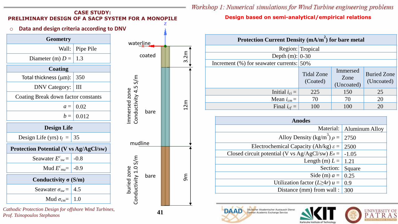
Prof. Tsinopoulos Stephanos41
waterline
mudline
coated
bare
bare
3.2
m1
2m
9m
Imm
erse
d z
on
eC
on
du
ctiv
ity
4.5
S/m
bu
ried
zo
ne
Co
nd
uct
ivit
y 1
.0 S
/m
CASE STUDY: PRELIMINARY DESIGN OF A SACP SYSTEM FOR A MONOPILE
o Data and design criteria according to DNV
Geometry
Wall: Pipe Pile
Diameter (m) D = 1.3
Protection Current Density (mA/m2) for bare metal
Region: Tropical
Depth (m): 0-30
Increment (%) for seawater currents: 50%
Tidal Zone
(Coated)
Immersed
Zone
(Uncoated)
Buried Zone
(Uncoated)
Initial ici = 225 150 25
Mean icm = 70 70 20
Final icf = 100 100 20
Anodes
Material: Aluminum Alloy
Alloy Density (kg/m3) ρ = 2750
Electrochemical Capacity (Ah/kg) ε = 2500
Closed circuit potential (V vs Ag/AgCl/sw) Ea = -1.05
Length (m) L = 1.21
Section: Square
Side (m) a = 0.25
Utilization factor (L≥4r) u = 0.9
Distance (mm) from wall : 300
Protection Potential (V vs Ag/AgCl/sw)
Seawater Ecsw = -0.8
Mud Ecmu= -0.9
Coating
Total thickness (μm): 350
DNV Category: III
Coating Break down factor constants
a = 0.02
b = 0.012
Design Life
Design Life (yrs) tf = 35
Conductivity σ (S/m)
Seawater σsw = 4.5
Mud σcm= 1.0
Design based on semi-analytical/empirical relations
Cathodic Protection Design for offshore Wind Turbines,
Prof. Tsinopoulos Stephanos42
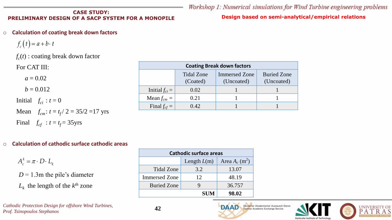
CASE STUDY: PRELIMINARY DESIGN OF A SACP SYSTEM FOR A MONOPILE
o Calculation of coating break down factors
( ) = + cf t a b t
fc(t) : coating break down factor
For CAT III:
a = 0.02
b = 0.012
Initial fci : t = 0
Mean fcm : t = tf / 2 = 35/2 =17 yrs
Final fcf : t = tf = 35yrs
Coating Break down factors
Tidal Zone
(Coated)
Immersed Zone
(Uncoated)
Buried Zone
(Uncoated)
Initial fci = 0.02 1 1
Mean fcm = 0.21 1 1
Final fcf = 0.42 1 1
o Calculation of cathodic surface cathodic areas
= k
c kA D L
D = 1.3m the pile’s diameter
Lk the length of the kth zone
Cathodic surface areas
Length L(m) Area Ac (m2)
Tidal Zone 3.2 13.07
Immersed Zone 12 48.19
Buried Zone 9 36.757
SUM 98.02
Design based on semi-analytical/empirical relations
Cathodic Protection Design for offshore Wind Turbines,
Prof. Tsinopoulos Stephanos43
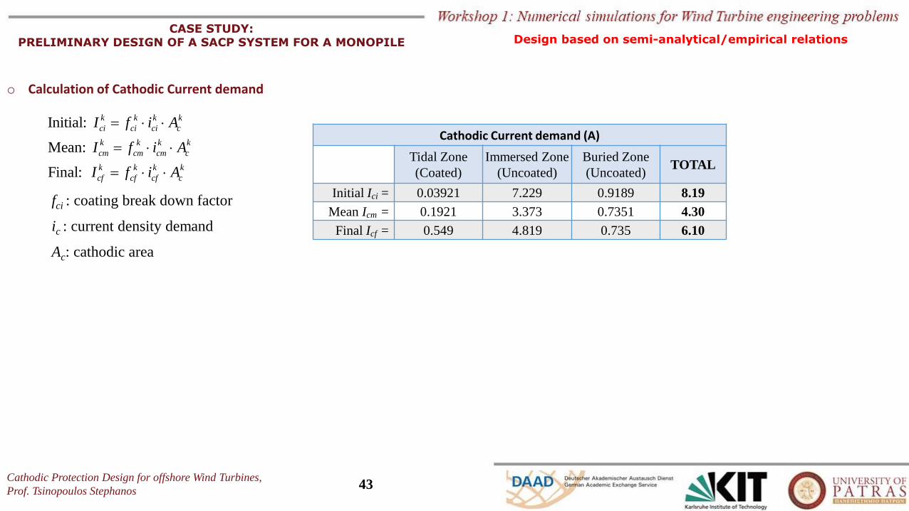
CASE STUDY: PRELIMINARY DESIGN OF A SACP SYSTEM FOR A MONOPILE
o Calculation of Cathodic Current demand
Initial:
Mean:
Final:
k k k k
ci ci ci c
k k k k
cm cm cm c
k k k k
cf cf cf c
I f i A
I f i A
I f i A
=
=
=
Cathodic Current demand (A)
Tidal Zone
(Coated)
Immersed Zone
(Uncoated)
Buried Zone
(Uncoated)TOTAL
Initial Ici = 0.03921 7.229 0.9189 8.19
Mean Icm = 0.1921 3.373 0.7351 4.30
Final Icf = 0.549 4.819 0.735 6.10
fci : coating break down factor
ic : current density demand
Ac: cathodic area
Design based on semi-analytical/empirical relations
Cathodic Protection Design for offshore Wind Turbines,
Prof. Tsinopoulos Stephanos44
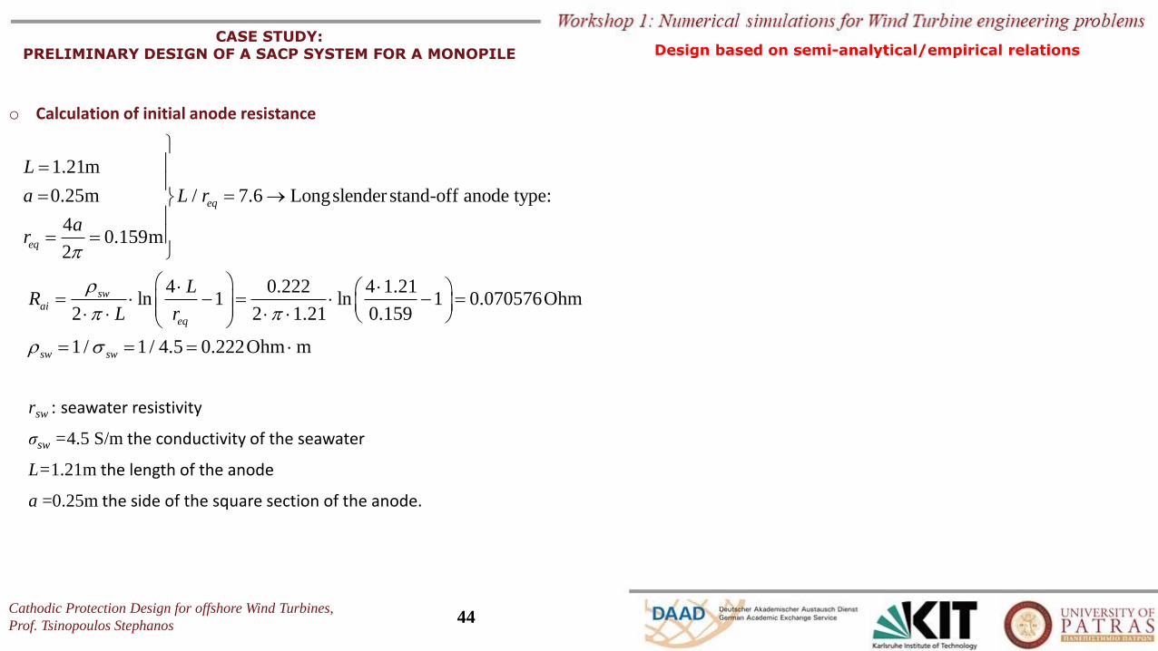
CASE STUDY: PRELIMINARY DESIGN OF A SACP SYSTEM FOR A MONOPILE
o Calculation of initial anode resistance
rsw : seawater resistivity
σsw =4.5 S/m the conductivity of the seawater
L=1.21m the length of the anode
a =0.25m the side of the square section of the anode.
1.21m
0.25m / 7.6 Longslender stand-off anode type:
40.159m
2
eq
eq
L
a L r
ar
=
= = →= =
4 0.222 4 1.2
m
1ln 1 ln 1 0.070576Ohm
2 2 1.21 0.159
1 / 1 / 4.5 0.222Ohmsw sw
swai
eq
LR
L r
=
= =
= − = −
=
Design based on semi-analytical/empirical relations
Cathodic Protection Design for offshore Wind Turbines,
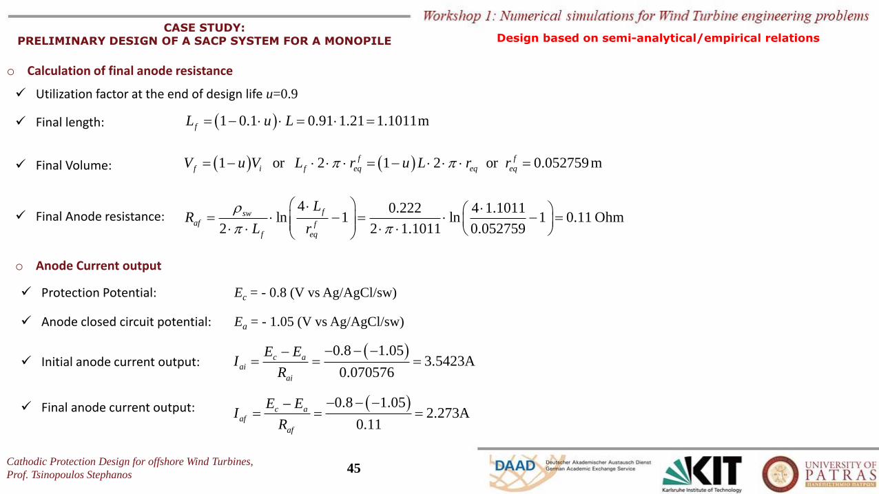
Prof. Tsinopoulos Stephanos45
CASE STUDY: PRELIMINARY DESIGN OF A SACP SYSTEM FOR A MONOPILE
o Calculation of final anode resistance
( ) ( ) 0.052759m1 or 2 1 2 orf f
f i f eq eq eqV u V L r u L r r = − = − =
0.110.052
n4 0.222 4 1.1011
ln 1 l 1 Ohm. 752 2 1 1011 9
fswaf f
f eq
LR
L r
= − = − =
✓ Final Volume:
( )1 0.1 0.91 1.21 1.1011mfL u L= − = =✓ Final length:
✓ Utilization factor at the end of design life u=0.9
✓ Final Anode resistance:
o Anode Current output
( )0.8 1.05A
0. 63.5423
07057
c aai
ai
E EI
R
− − −−= = =
✓ Protection Potential: Ec = - 0.8 (V vs Ag/AgCl/sw)
✓ Anode closed circuit potential: Ea = - 1.05 (V vs Ag/AgCl/sw)
✓ Initial anode current output:
✓ Final anode current output: ( )2.273
0.11
0.8 1.05Ac a
af
af
E EI
R
− − −−= = =
Design based on semi-analytical/empirical relations
Cathodic Protection Design for offshore Wind Turbines,
Prof. Tsinopoulos Stephanos46
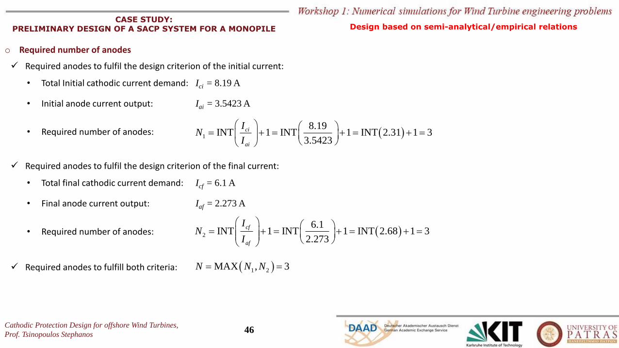
CASE STUDY: PRELIMINARY DESIGN OF A SACP SYSTEM FOR A MONOPILE
o Required number of anodes
✓ Required anodes to fulfil the design criterion of the initial current:
• Total Initial cathodic current demand: Ici = 8.19 A
• Initial anode current output: Iai = 3.5423 A
• Required number of anodes: ( )1
8.19INT 1 INT 1 INT 2.31 1 3
3.5423
ci
ai
IN
I
= + = + = + =
✓ Required anodes to fulfil the design criterion of the final current:
• Total final cathodic current demand: Icf = 6.1 A
• Final anode current output: Iaf = 2.273 A
• Required number of anodes: ( )2
6.1INT 1 INT 1 INT 2.68 1 3
2.273
cf
af
IN
I
= + = + = + =
✓ Required anodes to fulfill both criteria: ( )1 2MAX , 3N N N= =
Design based on semi-analytical/empirical relations
Cathodic Protection Design for offshore Wind Turbines,
Prof. Tsinopoulos Stephanos47
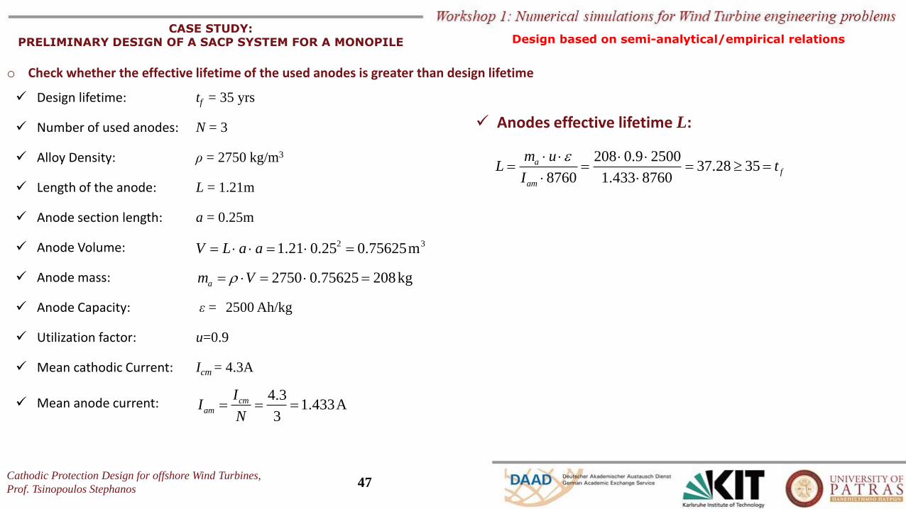
CASE STUDY: PRELIMINARY DESIGN OF A SACP SYSTEM FOR A MONOPILE
o Check whether the effective lifetime of the used anodes is greater than design lifetime
✓ Design lifetime: tf = 35 yrs
✓ Number of used anodes: N = 3
✓ Alloy Density: ρ = 2750 kg/m3
✓ Length of the anode: L = 1.21m
✓ Anode section length: a = 0.25m
✓ Anode Volume:
✓ Anode mass:
✓ Anode Capacity: ε = 2500 Ah/kg
✓ Utilization factor: u=0.9
✓ Mean cathodic Current: Icm = 4.3A
✓ Mean anode current:
2 31.21 0.25 0.75625mV L a a= = =
2750 0.75625 208kgam V= = =
208 0.9 250037.28 35
8760 1.433 8760
af
am
m uL t
I
= = = =
A4.
.3
1 4333
cmam
II
N= = =
✓ Anodes effective lifetime L:
Design based on semi-analytical/empirical relations
Cathodic Protection Design for offshore Wind Turbines,
Prof. Tsinopoulos Stephanos48
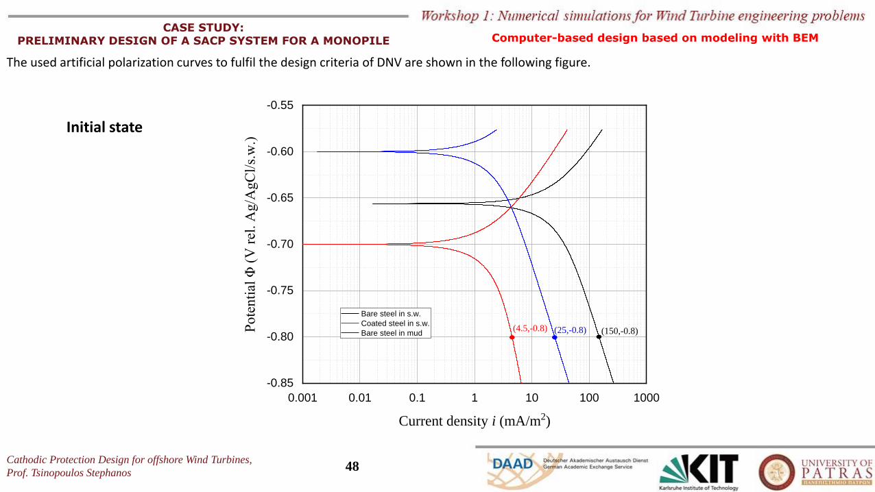
CASE STUDY: PRELIMINARY DESIGN OF A SACP SYSTEM FOR A MONOPILE Computer-based design based on modeling with BEM
The used artificial polarization curves to fulfil the design criteria of DNV are shown in the following figure.
Initial state
0.001 0.01 0.1 1 10 100 1000
-0.85
-0.80
-0.75
-0.70
-0.65
-0.60
-0.55
Pote
nti
al Φ
(V
rel
. A
g/A
gC
l/s.
w.)
Current density i (mA/m2)
Bare steel in s.w.
Coated steel in s.w.
Bare steel in mud (150,-0.8)(25,-0.8)(4.5,-0.8)
Cathodic Protection Design for offshore Wind Turbines,
Prof. Tsinopoulos Stephanos49
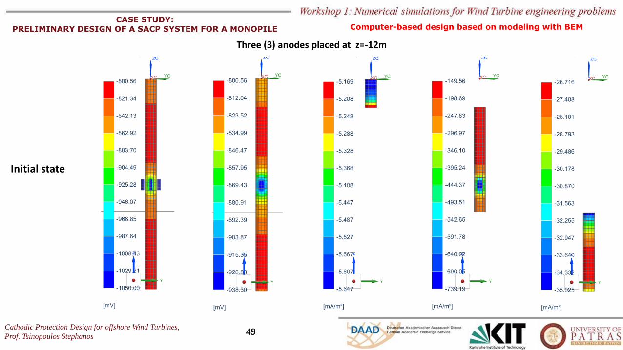
CASE STUDY: PRELIMINARY DESIGN OF A SACP SYSTEM FOR A MONOPILE
Three (3) anodes placed at z=-12m
Initial state
Computer-based design based on modeling with BEM
Cathodic Protection Design for offshore Wind Turbines,
Prof. Tsinopoulos Stephanos50
CASE STUDY: PRELIMINARY DESIGN OF A SACP SYSTEM FOR A MONOPILE
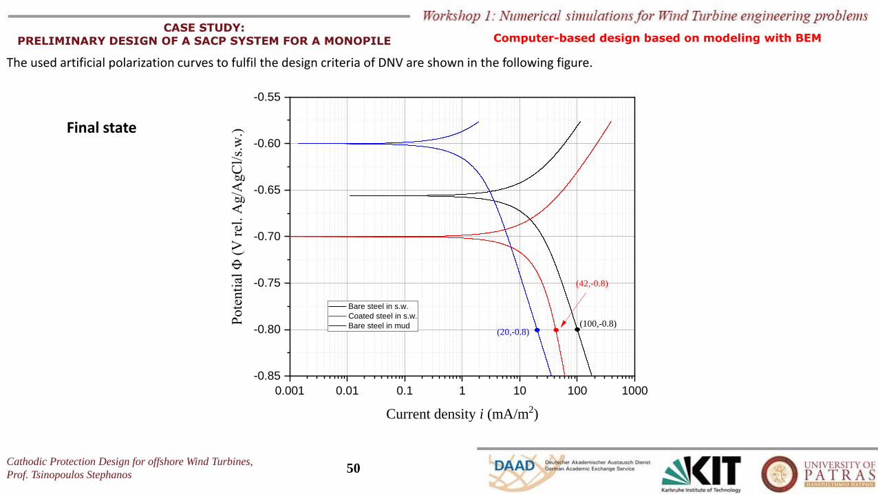
The used artificial polarization curves to fulfil the design criteria of DNV are shown in the following figure.
Final state
0.001 0.01 0.1 1 10 100 1000
-0.85
-0.80
-0.75
-0.70
-0.65
-0.60
-0.55
Pote
nti
al Φ
(V
rel
. A
g/A
gC
l/s.
w.)
Current density i (mA/m2)
Bare steel in s.w.
Coated steel in s.w.
Bare steel in mud (100,-0.8)(20,-0.8)
(42,-0.8)
Computer-based design based on modeling with BEM
Cathodic Protection Design for offshore Wind Turbines,
Prof. Tsinopoulos Stephanos51
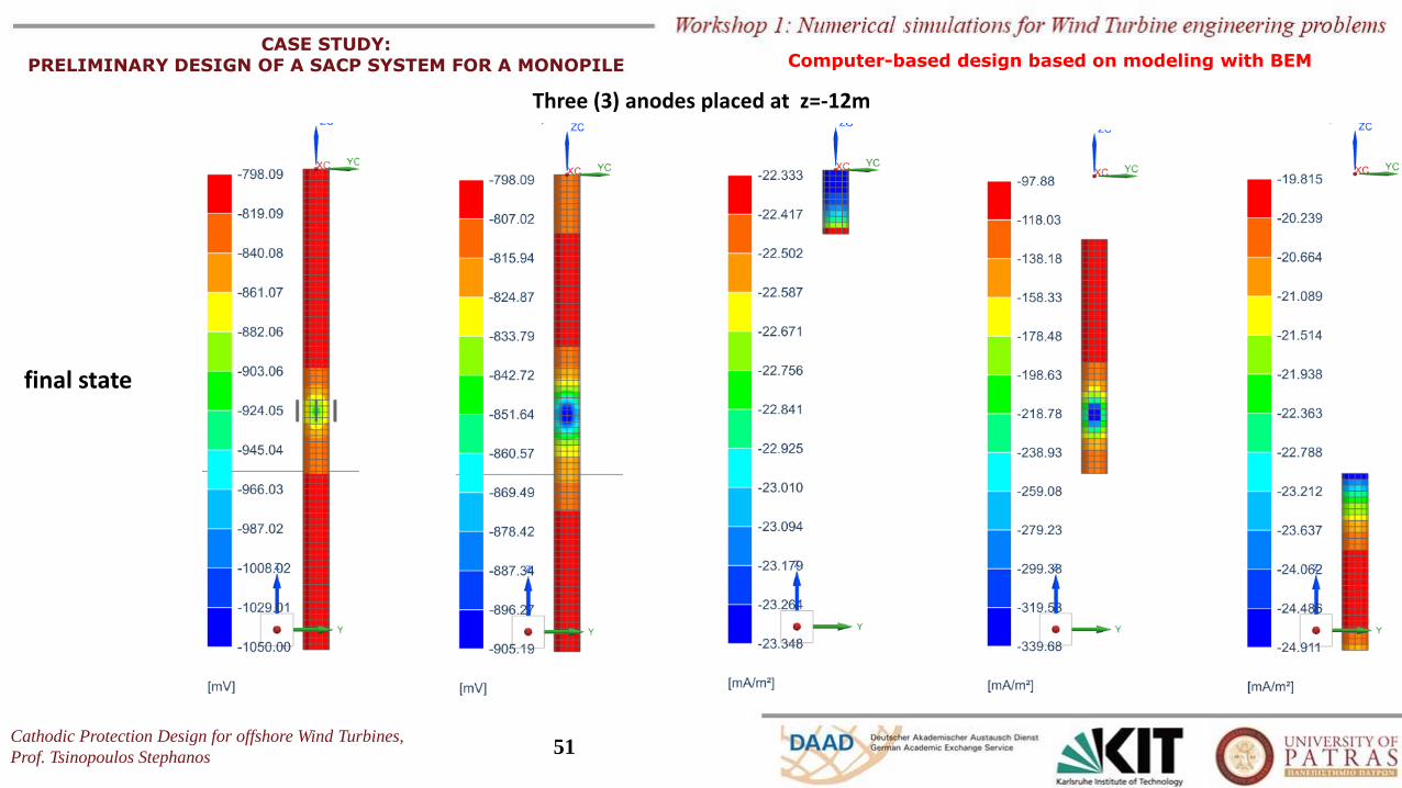
CASE STUDY: PRELIMINARY DESIGN OF A SACP SYSTEM FOR A MONOPILE
final state
Three (3) anodes placed at z=-12m
Computer-based design based on modeling with BEM
Cathodic Protection Design for offshore Wind Turbines,
Prof. Tsinopoulos Stephanos52
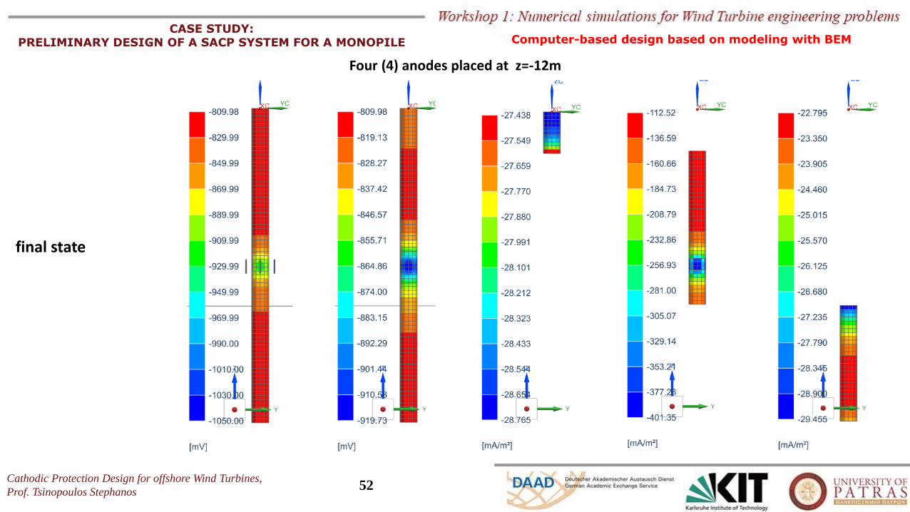
CASE STUDY: PRELIMINARY DESIGN OF A SACP SYSTEM FOR A MONOPILE
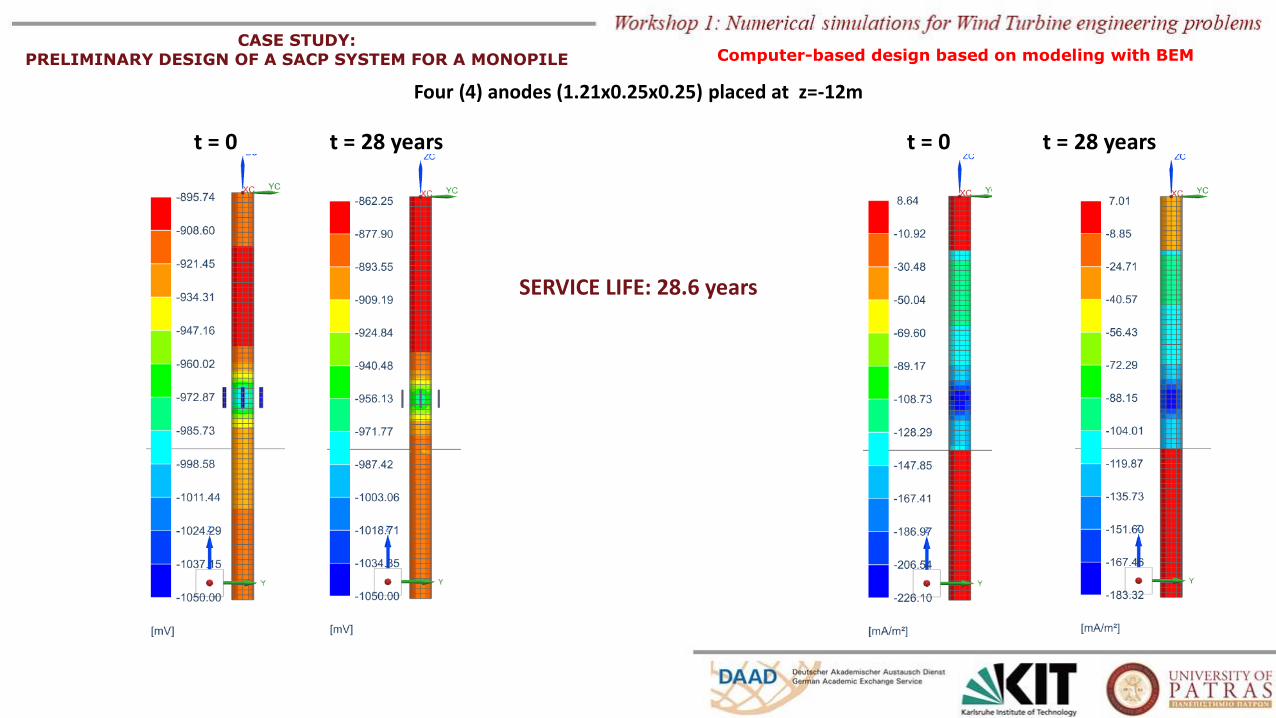
final state
Four (4) anodes placed at z=-12m
Computer-based design based on modeling with BEM
Cathodic Protection Design for offshore Wind Turbines,
Prof. Tsinopoulos Stephanos53
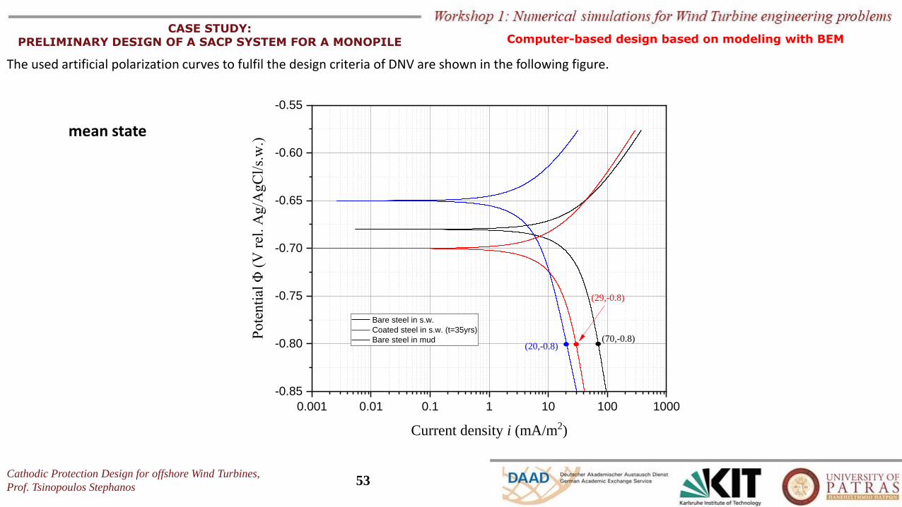
CASE STUDY: PRELIMINARY DESIGN OF A SACP SYSTEM FOR A MONOPILE
The used artificial polarization curves to fulfil the design criteria of DNV are shown in the following figure.
mean state
0.001 0.01 0.1 1 10 100 1000
-0.85
-0.80
-0.75
-0.70
-0.65
-0.60
-0.55
Pote
nti
al Φ
(V
rel
. A
g/A
gC
l/s.
w.)
Current density i (mA/m2)
Bare steel in s.w.
Coated steel in s.w. (t=35yrs)
Bare steel in mud (70,-0.8)(20,-0.8)
(29,-0.8)
Computer-based design based on modeling with BEM
t = 0
SERVICE LIFE: 28.6 years
Four (4) anodes (1.21x0.25x0.25) placed at z=-12m
CASE STUDY: PRELIMINARY DESIGN OF A SACP SYSTEM FOR A MONOPILE
t = 28 years t = 0 t = 28 years
Computer-based design based on modeling with BEM
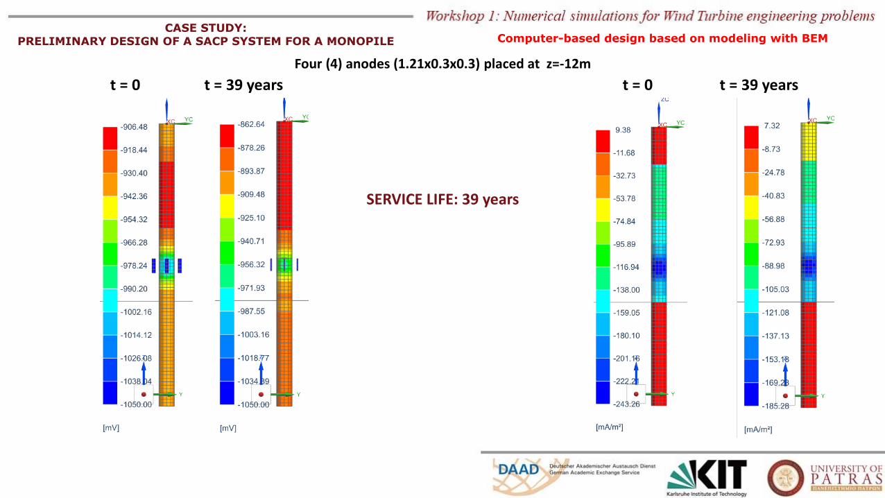
SERVICE LIFE: 39 years
Four (4) anodes (1.21x0.3x0.3) placed at z=-12m
CASE STUDY: PRELIMINARY DESIGN OF A SACP SYSTEM FOR A MONOPILE Computer-based design based on modeling with BEM
t = 0 t = 39 years t = 0 t = 39 years
REFERENCES
o Det Norske Veritas (2017), Recommended Practice DNVGL-RP-B401: Cathodic protection design, DNV, Oslo, Norway
o Det Norske Veritas (2016), Recommended Practice DNVGL-RP-0416: Cathodic protection for wind turbines, DNV, Oslo, Norway
o British Standards Institution (2000), BS EN 12473:2000: General principles of cathodic protection in sea waters , BSI, London, UK
o British Standards Institution (2000), BS EN 12495:2000: Cathodic protection for fixed steel offshore structures, BSI, London, UK
o British Standards Institution (2001), BS EN 13174:2001: Cathodic protection for harbour installations, BSI, London, UK
o NACE International (2003), NACE Standard RP0176-2003: Corrosion control pf steel fixed offshore structures associated with petroleum
production, Houston, Texas, USA
o G. Masi, F. Matteucci, J. Tacq, A. Balbo (2018), State of the art study on materials and solutions against corrosion in offshore structures, North
sea solutions for innovation in corrosion for energy (NeSSIE) project.
o Rodopoulos D.C., Gortsas T.V., Tsinopoulos S.V., Polyzos D. (2019), ACA/BEM for solving large-scale cathodic protection problems, Engineering
Analysis with Boundary Elements, 106, pp. 139-148
o Kalovelonis D.T., Rodopoulos D.C., Gortsas T.V., Polyzos D. and Tsinopoulos S.V. (2019), Cathodic Protection of a Container Ship Using a Detailed
BEM Model, Journal of Marine Science and Engineering, 8(5), pp. 1-14
Cathodic Protection Design for offshore Wind Turbines,
Prof. Tsinopoulos Stephanos57
Cathodic Protection Design
for
offshore Wind Turbines
End of the presentation
Thank you for your attention and patience!