Embed Size (px)
Citation preview
OFF
ON
MENU6 °C
3SET SENSORSGAUGES
POINT
MAIN MENU
ALARMS
NEXTEXIT SELECT
NO ALARMS
NO ALARMS0 OF 0 ALARMS
EXIT
ALARM 28
PRETRIP ABORT1 OF 1 ALARMS
EXIT CLEAR HELP
ALARM 28
PRETRIP ABORT1 OF 1 ALARMS
EXIT CLEAR HELP
MENU6 °C
3SET SENSORSGAUGES
POINT
.1
TK 55526-2-PC-EN (Rev. 1, 08-16) ©Thermo King Corporation
83 LowEngineCoolantTemperature84 RestartNull85 ForcedUnitOperation86 DischargePressureSensor87 SuctionPressureSensor89 CheckElectronicThrottlingValveCircuit90 ElectricOverload91 ElectricReadyInput92 SensorGradesNotSet93 LowCompressorSuctionPressure94 Loader#1Circuit95 Loader#2Circuit96 LowFuelLevel98 FuelLevelSensor99 HighCompressorPressureRatio108 DoorOpenTime-out111 UnitNotConfiguredCorrectly113 ElectricHeatCircuit114 MultipleAlarms-CannotRun115 CheckHighPressureCutoutSwitch116 CheckHighPressureCutInSwitch117 AutoSwitchfromDieseltoElectric118 AutoSwitchfromElectrictoDiesel120 AlternatorExciterCircuit121 LiquidInjectionCircuit122 Diesel/ElectricRelayCircuit127 SetpointNotEntered128 EngineRunTimeMaintenanceReminder#1129 EngineRunTimeMaintenanceReminder#2130 ElectricRunTimeMaintenanceReminder#1131 ElectricRunTimeMaintenanceReminder#2132 TotalUnitRunTimeMaintenanceReminder#1133 TotalUnitRunTimeMaintenanceReminder#2134 ControllerPowerOnHours135 CheckSpareDigitalInputs136 CheckSpareDigitalOutputs137 CheckDamperMotorHeaterOutput141 AutoswitchDieseltoElectricDisabled145 LossofController“On”FeedbackSignal146 SoftwareVersionMismatch148 AutoswitchElectrictoDieselDisabled149 AlarmNotIdentified150 OutofRangeLow151 OutofRangeHigh157 OptiSetPlusMismatch158 Softwarefailedtoload203 DisplayReturnAirSensor204 DisplayDischargeAirSensor252 CheckFreshAirExchangeCircuit
SIMPLE TO VIEW
CauseofAlarm
SIMPLE TO DETERMINE
CauseofAlarm
2
1
4
6
3
5
7
13
2
1. ReturntotheStandardDisplayScreen.
2. PresstheMENUKey.3. PresstheNEXTKeyuntiltheAlarm
Menuappears.4. PresstheSELECTKey.TheAlarm
Displaywillappear5. Ifnoalarmsarepresent,Alarm00
isshown.6. PresstheEXITKeytoreturntothe
StandardDisplay.7. Ifalarmsarepresent,thenumberof
alarmsandthemostrecentalarmcodenumberwillbeshown.
8. Ifthereismorethanonealarm,presstheNEXTKeytovieweachalarm.
9. Ifaseriousalarmoccurs,theunitwillbeshutdowntopreventdamagetotheunitortheload.Ifthisoccurs,thedisplaywillshowthattheunitisshutdownanddisplaythealarmcodethatcausedtheshutdown.
1. PresstheCLEARKeytoclearanalarm.
2. ThedisplayscreenwillreturntotheStandardDisplaywhenthealarmsarecleared.
3. PresstheHELPkeyforadditionalinformationwnonthedisplay.AlsoseethecompleteAlarmCodelistinthenextcolumn.
0 NoAlarmsExist2 EvaporatorCoilSensor3 ControlReturnAirSensor4 ControlDischargeAirSensor5 AmbientAirSensor6 CoolantTempSensor7 EngineRPMSensor9 HighEvaporatorTemperature10 HighDischargePressure11 UnitControllingonAlternateSensor12 SensororDigitalInputShutdown13 SensorCheck15 CheckGlowPlugs/IntakeAirHeater17 EngineFailedtoCrank18 HighEngineCoolantTemperature19 LowEngineOilPressure20 EngineFailedtoStart21 CoolingCycleCheck22 HeatingCycleCheck23 CoolingCycleFault24 HeatingCycleFault25 AlternatorCheck26 RefrigerationCapacity28 PretriporSelfCheckAbort29 DefrostDamperCircuit30 DefrostDamperStuck31 OilPressureSwitch32 RefrigerationCapacityLow33 CheckEngineRPM35 RunRelayCircuit36 ElectricMotorFailedtoRun37 EngineCoolantLevel38 ElectricPhaseReversed39 WaterValveCircuit40 HighSpeedCircuit41 CheckEngineCoolantTemperature42 UnitForcedtoLowSpeed43 UnitForcedtoLowSpeedModulation44 CheckFuelSystem45 HotGasBypassorHotGasBypassCircuit46 CheckAirFlow48 CheckBelts/Clutch50 ResetClock52 HeatCircuit54 TestModeTime-out61 LowBatteryVoltage62 AmmeterOutofCalibration63 EngineStopped64 PretripReminder65 AbnormalTemperatureDifferential66 LowEngineOilLevel67 LiquidLineSolenoidCircuit68 InternalControllerFault70 HourmeterFailure74 ControllerResettoDefaults77 ControllerEPROMChecksumFailure79 InternalDataLoggerOverflow80 CompresorTempSensor81 HighCompressorTemp82 HighCompressorTemperatureShutdown
SIMPLE TO VIEW
ClearingAlarmCodes
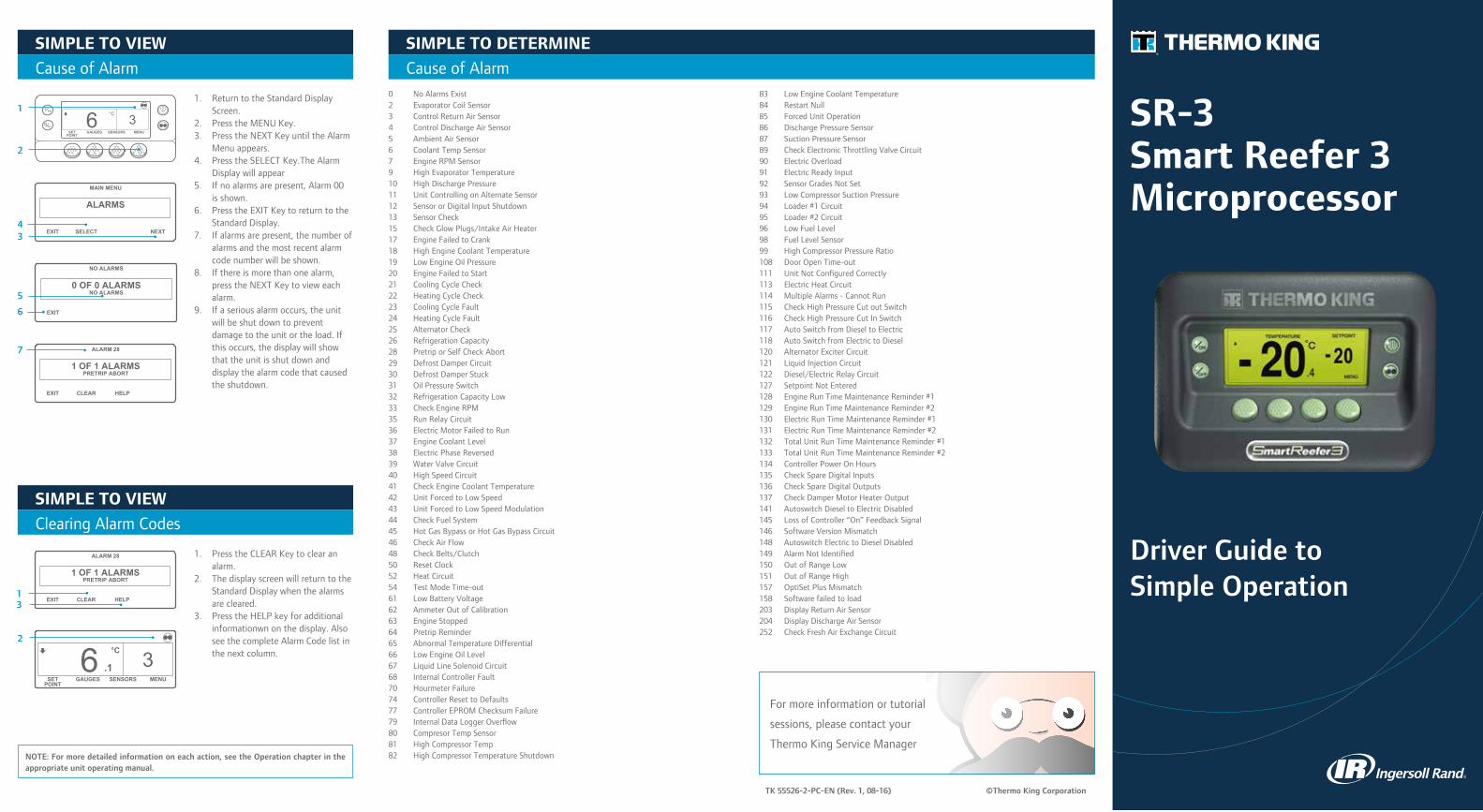
Driver Guide to Simple Operation
SR-3Smart Reefer 3Microprocessor
NOTE: For more detailed information on each action, see the Operation chapter in the appropriate unit operating manual.
Formoreinformationortutorial
sessions,pleasecontactyour
ThermoKingServiceManager
OFF
ON
MENU6 °C
3SET SENSORSGAUGES
POINT
OFF
ON
MENU6 °C
3SET SENSORSGAUGES
POINT
OFF
ON
MENU6 °C
3SET SENSORSGAUGES
POINT
OFF
ON
MENU6 °C
3SET SENSORSGAUGES
POINT
OFF
ON
MENU6 °C
3SET SENSORSGAUGES
POINT
OFF
ON
MENU6 °C
3SET SENSORSGAUGES
POINT
OFF
ON
MENU6 °C
3SET SENSORSGAUGES
POINT
OFF
ON
MENU6 °C
3SET SENSORSGAUGES
POINTMENU6 °C
3SET SENSORSGAUGES
POINT
.1
PROGRAMMING DEFROST
PLEASE WAIT
MAIN MENU
PRETRIP
NEXTEXIT SELECT BACK
TOTAL RUN TIME HOURS
78NEXTEXIT BACK
3MENUSET SENSORSGAUGES
POINTEXIT
PRETRIPPASS
- EXIT
CURRENT SETPOINT
3 C
++/- TO CHANGE
- NO
NEW SETPOINT WILL BE
4 C
++/- TO CHANGE OK?YES
MENU2 °C
4SET SENSORSGAUGES
POINT
.1
2 2
1 1
ENGINE RPM
1457NEXTEXIT LOCK
RPM
BACK
ENGINE RPM
1457NEXTEXIT LOCK
RPM
BACK
4 45 53 3
5
3 & 5
7
3 3
43
4
2
1
3
1
4
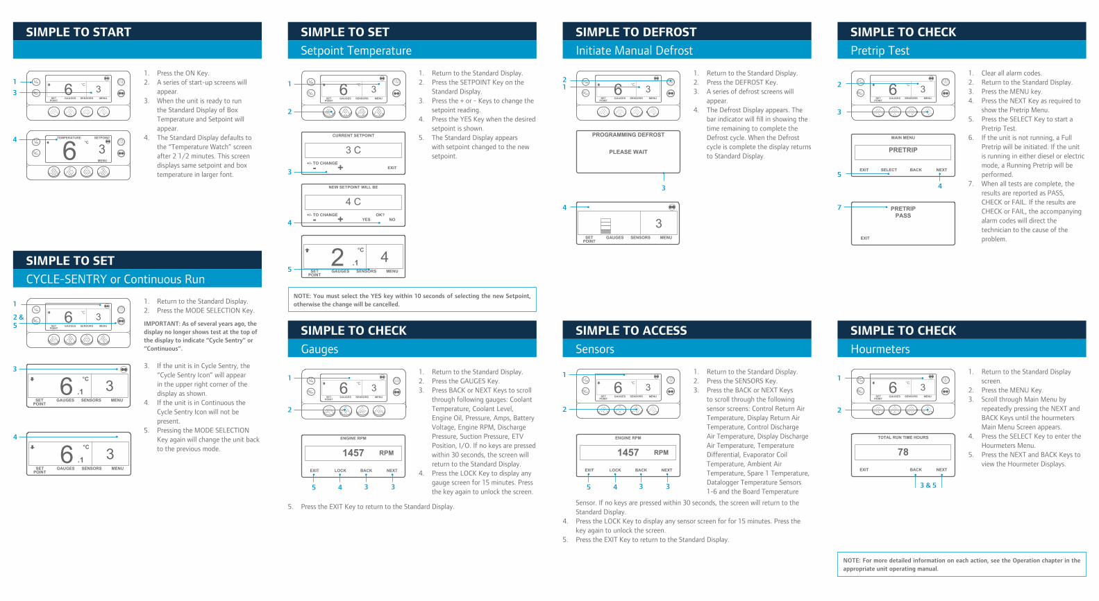
1. PresstheONKey.2. Aseriesofstart-upscreenswill
appear.3. Whentheunitisreadytorun
theStandardDisplayofBoxTemperatureandSetpointwillappear.
4. TheStandardDisplaydefaultstothe“TemperatureWatch”screenafter21/2minutes.Thisscreendisplayssamesetpointandboxtemperatureinlargerfont.
1. ReturntotheStandardDisplay.2. PresstheSETPOINTKeyonthe
StandardDisplay.3. Pressthe+or-Keystochangethe
setpointreading.4. PresstheYESKeywhenthedesired
setpointisshown.5. TheStandardDisplayappears
withsetpointchangedtothenewsetpoint.
1. ReturntotheStandardDisplay.2. PresstheMODESELECTIONKey.
IMPORTANT: As of several years ago, the display no longer shows test at the top of the display to indicate “Cycle Sentry” or “Continuous”.
3. IftheunitisinCycleSentry,the“CycleSentryIcon”willappearintheupperrightcornerofthedisplayasshown.
4. IftheunitisinContinuoustheCycleSentryIconwillnotbepresent.
5. PressingtheMODESELECTIONKeyagainwillchangetheunitbacktothepreviousmode.
SIMPLE TO START
SIMPLE TO SET
CYCLE-SENTRYorContinuousRun
SIMPLE TO SET
SetpointTemperature
SIMPLE TO CHECK
Gauges
SIMPLE TO DEFROST
InitiateManualDefrost
SIMPLE TO ACCESS
Sensors
SIMPLE TO CHECK
PretripTest
SIMPLE TO CHECK
Hourmeters
1
3
4
2 & 5
MENU6 °C
3SET SENSORSGAUGES
POINT
.1
3
4
5
2
1
1. ReturntotheStandardDisplay.2. PresstheDEFROSTKey.3. Aseriesofdefrostscreenswill
appear.4. TheDefrostDisplayappears.The
barindicatorwillfillinshowingthetimeremainingtocompletetheDefrostcycle.WhentheDefrostcycleiscompletethedisplayreturnstoStandardDisplay.
12
2
3
NOTE: For more detailed information on each action, see the Operation chapter in the appropriate unit operating manual.
1. ReturntotheStandardDisplay.2. PresstheGAUGESKey.3. PressBACKorNEXTKeystoscroll
throughfollowinggauges:CoolantTemperature,CoolantLevel,EngineOil,Pressure,Amps,BatteryVoltage,EngineRPM,DischargePressure,SuctionPressure,ETVPosition,I/O.Ifnokeysarepressedwithin30seconds,thescreenwillreturntotheStandardDisplay.
4. PresstheLOCKKeytodisplayanygaugescreenfor15minutes.Pressthekeyagaintounlockthescreen.
1. Clearallalarmcodes.2. ReturntotheStandardDisplay.3. PresstheMENUkey.4. PresstheNEXTKeyasrequiredto
showthePretripMenu.5. PresstheSELECTKeytostarta
PretripTest.6. Iftheunitisnotrunning,aFull
Pretripwillbeinitiated.Iftheunitisrunningineitherdieselorelectricmode,aRunningPretripwillbeperformed.
7. Whenalltestsarecomplete,theresultsarereportedasPASS,CHECKorFAIL.IftheresultsareCHECKorFAIL,theaccompanyingalarmcodeswilldirectthetechniciantothecauseoftheproblem.
1. ReturntotheStandardDisplayscreen.
2. PresstheMENUKey.3. ScrollthroughMainMenuby
repeatedlypressingtheNEXTandBACKKeysuntilthehourmetersMainMenuScreenappears.
4. PresstheSELECTKeytoentertheHourmetersMenu.
5. PresstheNEXTandBACKKeystoviewtheHourmeterDisplays.
1. ReturntotheStandardDisplay.2. PresstheSENSORSKey.3. PresstheBACKorNEXTKeys
toscrollthroughthefollowingsensorscreens:ControlReturnAirTemperature,DisplayReturnAirTemperature,ControlDischargeAirTemperature,DisplayDischargeAirTemperature,TemperatureDifferential,EvaporatorCoilTemperature,AmbientAirTemperature,Spare1Temperature,DataloggerTemperatureSensors1-6andtheBoardTemperature
Sensor.Ifnokeysarepressedwithin30seconds,thescreenwillreturntotheStandardDisplay.
4. PresstheLOCKKeytodisplayanysensorscreenforfor15minutes.Pressthekeyagaintounlockthescreen.
5. PresstheEXITKeytoreturntotheStandardDisplay.
5. PresstheEXITKeytoreturntotheStandardDisplay.
NOTE: You must select the YES key within 10 seconds of selecting the new Setpoint, otherwise the change will be cancelled.