Embed Size (px)
Citation preview

_____________________________________________________________________________________
r e v . 1 . 0 1 145 Rt. 46 West E‐mail: sales@electro‐set.net Wayne, NJ 07470 Web: www.Electro‐Set.net Tel: (973)689‐9960
1
1
CB-035 8 Digit 7-Segment Display
September 03, 2014
Introduction
This application note will show two minimal code set ups to operate the 7-segment display module CB-035 one with an Arduino board and the other with Cardinal’s CB-026 Microchip microcontroller module.
Arduino
The Arduino example will display 3 modes of the 8 digit 7-segment display, BCD, HEX and raw segment.
Before proceeding any further, please have the Arduino software install to your computer. Visit Arduino’s user setup guide at http://arduino.cc/en/Guide/windows for step-by-step instructions.
Hardware
Parts List:
Arduino Uno USB type B connector CB-I-022 Cardinal Interface Board CB-035 8 digit 7-segment display
_____________________________________________________________________________________
r e v . 1 . 0 1 145 Rt. 46 West E‐mail: sales@electro‐set.net Wayne, NJ 07470 Web: www.Electro‐Set.net Tel: (973)689‐9960
2
2
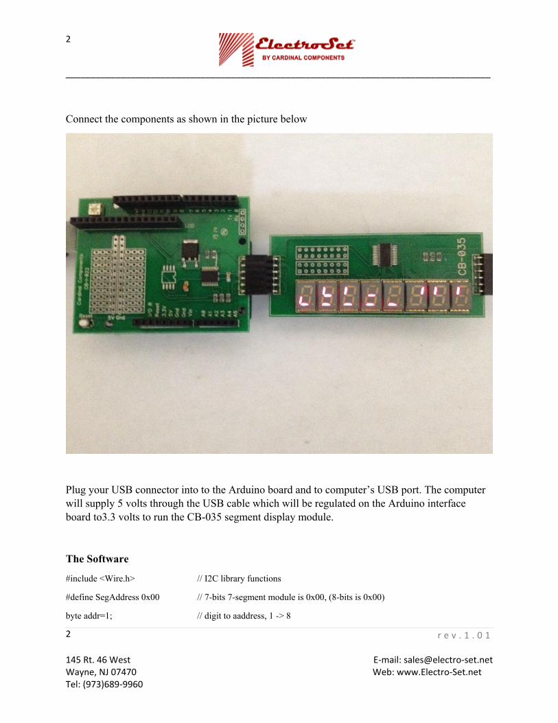
Connect the components as shown in the picture below
Plug your USB connector into to the Arduino board and to computer’s USB port. The computer will supply 5 volts through the USB cable which will be regulated on the Arduino interface board to3.3 volts to run the CB-035 segment display module.
The Software
#include <Wire.h> // I2C library functions
#define SegAddress 0x00 // 7-bits 7-segment module is 0x00, (8-bits is 0x00)
byte addr=1; // digit to aaddress, 1 -> 8

_____________________________________________________________________________________
r e v . 1 . 0 1 145 Rt. 46 West E‐mail: sales@electro‐set.net Wayne, NJ 07470 Web: www.Electro‐Set.net Tel: (973)689‐9960
3
3
int loopCount=0; // iteration count for the 'loop' function
int const Dy=300;
int errCount=0; // total errors to report
/* Function to write one data byte 'd' to the internal register 'a' at slave address SegAddress
Report any I2C errors to the serial monitor
*/
void I2Cwrite1byte(byte a,byte d);
void setup(){
Serial.begin(9600); // initialize serial monitor to 9600 baud
Serial.println("Electro-Set"); // welcome message
Serial.println("CB-035 Test"); // welcome message
Wire.begin(); // initialize I2C port
Wire.beginTransmission(SegAddress); // start of I2C tramsmission
Wire.write(9); // internal reg address 0x09, decode mode
Wire.write(0xff); // ->decode-mode reg
Wire.write(0x02); // ->global intensity reg, 0 through 7
Wire.write(0x07); // ->scan limit reg, number of 7 segment digits to activate
Wire.write(0x81); // ->shut down reg
Wire.endTransmission();
delay(10);
I2Cwrite1byte(14,0); // BCD, internal address of feature register, BCD
delay(1000); // delay for about 1 sec
}
int state=0; // We show 3 modes, BCD, HEX and raw segments
byte seg; // raw segment write variable
_____________________________________________________________________________________
r e v . 1 . 0 1 145 Rt. 46 West E‐mail: sales@electro‐set.net Wayne, NJ 07470 Web: www.Electro‐Set.net Tel: (973)689‐9960
4
4
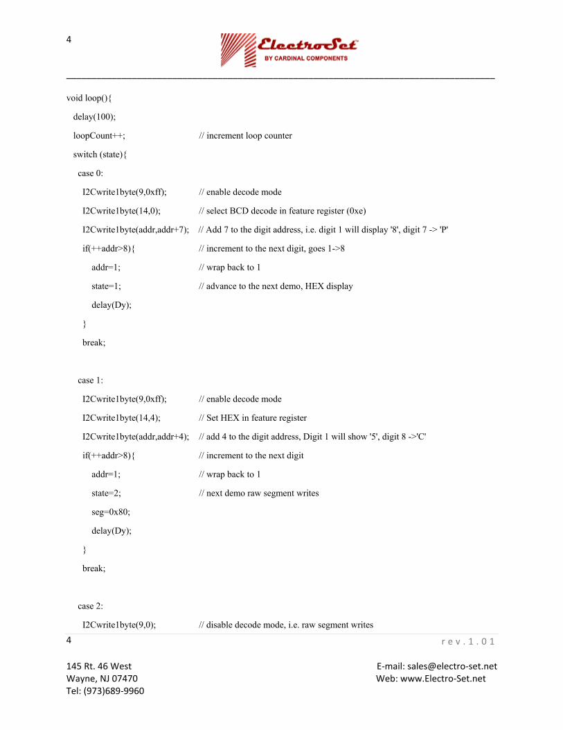
void loop(){
delay(100);
loopCount++; // increment loop counter
switch (state){
case 0:
I2Cwrite1byte(9,0xff); // enable decode mode
I2Cwrite1byte(14,0); // select BCD decode in feature register (0xe)
I2Cwrite1byte(addr,addr+7); // Add 7 to the digit address, i.e. digit 1 will display '8', digit 7 -> 'P'
if(++addr>8){ // increment to the next digit, goes 1->8
addr=1; // wrap back to 1
state=1; // advance to the next demo, HEX display
delay(Dy);
}
break;
case 1:
I2Cwrite1byte(9,0xff); // enable decode mode
I2Cwrite1byte(14,4); // Set HEX in feature register
I2Cwrite1byte(addr,addr+4); // add 4 to the digit address, Digit 1 will show '5', digit 8 ->'C'
if(++addr>8){ // increment to the next digit
addr=1; // wrap back to 1
state=2; // next demo raw segment writes
seg=0x80;
delay(Dy);
}
break;
case 2:
I2Cwrite1byte(9,0); // disable decode mode, i.e. raw segment writes
_____________________________________________________________________________________
r e v . 1 . 0 1 145 Rt. 46 West E‐mail: sales@electro‐set.net Wayne, NJ 07470 Web: www.Electro‐Set.net Tel: (973)689‐9960
5
5
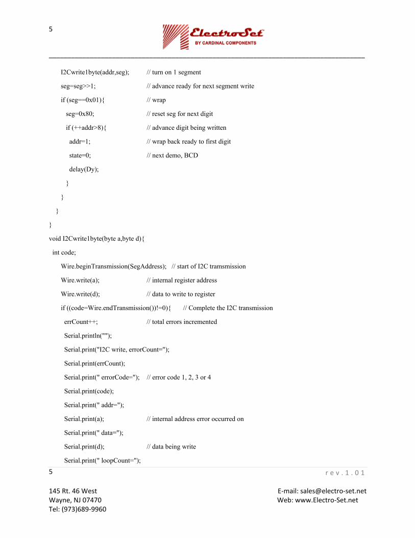
I2Cwrite1byte(addr,seg); // turn on 1 segment
seg=seg>>1; // advance ready for next segment write
if (seg==0x01){ // wrap
seg=0x80; // reset seg for next digit
if (++addr>8){ // advance digit being written
addr=1; // wrap back ready to first digit
state=0; // next demo, BCD
delay(Dy);
}
}
}
}
void I2Cwrite1byte(byte a,byte d){
int code;
Wire.beginTransmission(SegAddress); // start of I2C tramsmission
Wire.write(a); // internal register address
Wire.write(d); // data to write to register
if ((code=Wire.endTransmission())!=0){ // Complete the I2C transmission
errCount++; // total errors incremented
Serial.println("");
Serial.print("I2C write, errorCount=");
Serial.print(errCount);
Serial.print(" errorCode="); // error code 1, 2, 3 or 4
Serial.print(code);
Serial.print(" addr=");
Serial.print(a); // internal address error occurred on
Serial.print(" data=");
Serial.print(d); // data being write
Serial.print(" loopCount=");

_____________________________________________________________________________________
r e v . 1 . 0 1 145 Rt. 46 West E‐mail: sales@electro‐set.net Wayne, NJ 07470 Web: www.Electro‐Set.net Tel: (973)689‐9960
6
6
Serial.println(loopCount); // number of iterations of 'loop' when error occurred
}
}
Code Operation
The 7-segment display module has a 7-bit slave address as 0x00 which we make a #define
We next define a function prototype to write one data byte 'd' to the internal register 'a' to the device at slave address SegAddress.
void I2Cwrite1byte(byte a,byte d);
The setup() function is called when a sketch starts. The setup code, initializes the serial monitor baud rate at 9600, outputs a welcome message and then initializes the I2C port as a master. The 7-segment display will be blank, and will be in shutdown mode on initial power up and must be configured for normal operation. The code
Wire.beginTransmission(SegAddress); // start of I2C tramsmission
Wire.write(9); // internal reg address 0x09, decode mode
Wire.write(0xff); // ->decode-mode reg
Wire.write(0x02); // ->global intensity reg, 0 through 7
Wire.write(0x07); // ->scan limit reg, number of 7 segment digits to activate
Wire.write(0x81); // ->shut down reg
Wire.endTransmission();
Is used to initialize the display, it writes 4 data bytes to internal register addresses 0x09 through 0x0c.
Register 0x09 is the ‘decode enable register’, we write 0xff which enables decoding of all 8 digits of the display with either BCD or Hex decoding. The data written for each display digit is a byte value 0x0 through 0xf. With decode enabled, BCD decoding will display 0, 1, 2, 3, 4, 5, 6, 7, 8, 9, E, H, L, P and ‘–‘ respectively. For Hex decoding the display will be 0, 1, 2, 3, 4, 5, 6, 7, 8, 9, A, B, C, D, E, F respectively for data values written 0x0 through 0xf.
Register 0x0a is the ‘intensity control register’ we write a 0x02 which is on the dim side. Values range between minimum 0x00 and maximum 0x0f.
_____________________________________________________________________________________
r e v . 1 . 0 1 145 Rt. 46 West E‐mail: sales@electro‐set.net Wayne, NJ 07470 Web: www.Electro‐Set.net Tel: (973)689‐9960
7
7
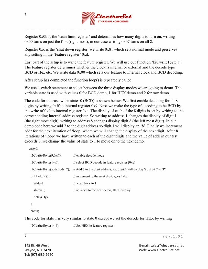
Register 0x0b is the ‘scan limit register’ and determines how many digits to turn on, writing 0x00 turns on just the first (right most), in our case writing 0x07 turns on all 8.
Register 0xc is the ‘shut down register’ we write 0x81 which sets normal mode and preserves any setting in the ‘feature register’ 0xd.
Last part of the setup is to write the feature register. We will use our function ‘I2Cwrite1byte()’. The feature register determines whether the clock is internal or external and the decode type BCD or Hex etc. We write data 0x00 which sets our feature to internal clock and BCD decoding.
After setup has completed the function loop() is repeatedly called.
We use a switch statement to select between the three display modes we are going to demo. The variable state is used with values 0 for BCD demo, 1 for HEX demo and 2 for raw demo.
The code for the case when state=0 (BCD) is shown below. We first enable decoding for all 8 digits by writing 0xff to internal register 0x9. Next we make the type of decoding to be BCD by the write of 0x0 to internal register 0xe. The display of each of the 8 digits is set by writing to the corresponding internal address register. So writing to address 1 changes the display of digit 1 (the right most digit), writing to address 8 changes display digit 8 (the left most digit). In our demo code here we add 7 to the digit address so digit 1 will display an ‘8’. Finally we increment addr for the next iteration of ‘loop’ where we will change the display of the next digit. After 8 iterations of ‘loop’ we have written to each of the eight digits and the value of addr in our test exceeds 8, we change the value of state to 1 to move on to the next demo.
case 0:
I2Cwrite1byte(9,0xff); // enable decode mode
I2Cwrite1byte(14,0); // select BCD decode in feature register (0xe)
I2Cwrite1byte(addr,addr+7); // Add 7 to the digit address, i.e. digit 1 will display '8', digit 7 -> 'P'
if(++addr>8){ // increment to the next digit, goes 1->8
addr=1; // wrap back to 1
state=1; // advance to the next demo, HEX display
delay(Dy);
}
break;
The code for state 1 is very similar to state 0 except we set the decode for HEX by writing
I2Cwrite1byte(14,4); // Set HEX in feature register

_____________________________________________________________________________________
r e v . 1 . 0 1 145 Rt. 46 West E‐mail: sales@electro‐set.net Wayne, NJ 07470 Web: www.Electro‐Set.net Tel: (973)689‐9960
8
8
After the 8 iteration for state 1 we progress to state 2.
The code for state=2 is shown below.
case 2:
I2Cwrite1byte(9,0); // disable decode mode, i.e. raw segment writes
I2Cwrite1byte(addr,seg); // turn on 1 segment
seg=seg>>1; // advance seg, ready for next segment write
if (seg==0x00){ // wrap
seg=0x80; // reset seg for next digit
if (++addr>8){ // advance digit being written
addr=1; // wrap back ready to first digit
state=0; // next demo, BCD
delay(Dy);
}
}
Here we turn of the decode feature for all 8 digits by writing 0x0 to feature register 0x9. In this demo we generate a walking 1 in the variable seg. Each iteration of ‘loop’ whilst in state=2, the value, in the variable seg, has the ‘1’ moved along starting at 10000000, to 01000000 all the way to 00000001. On the write of the last segment of digit 1 a ‘-‘ is displayed, the walking one shift beyond the last bit of the byte and seg=0, we detect this, reset seg to 0x80 and increment addr so we address the next display digit. Finally when all 8 digits have been exercised state is returned to zero to repeat the sequence.
The final piece of code is the definition of I2Cwrite1byte().
The Wire function ‘Wire.endTransmission()’ returns zero if everything went smoothly otherwise an error code of 1, 2 3, or 4 is returned. We detect this error case with the following code and report the error occurrence through the serial monitor port.
if ((code=Wire.endTransmission())!=0){ // Complete the I2C transmission
See the Arduino reference on ‘Wire.endTransmission’ for more information.
Microchip Module CB-026
_____________________________________________________________________________________
r e v . 1 . 0 1 145 Rt. 46 West E‐mail: sales@electro‐set.net Wayne, NJ 07470 Web: www.Electro‐Set.net Tel: (973)689‐9960
9
9
The CB-026 example in PICBASIC PRO will read the digital value from the temperature module and output a decimal value via the serial port to a terminal emulator such as hyperterminal
Before proceeding any further, please have the MicroCode Studio PICBASIC PRO suite installed on your computer.
Hardware
Parts List:
Electro-Set module CB-026 microcontroller USB type mini connector CB-035 8 Digit 7-segment Display
_____________________________________________________________________________________
r e v . 1 . 0 1 145 Rt. 46 West E‐mail: sales@electro‐set.net Wayne, NJ 07470 Web: www.Electro‐Set.net Tel: (973)689‐9960
10
10
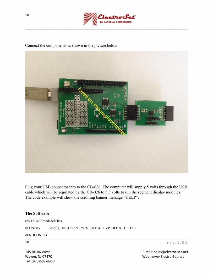
Connect the components as shown in the picture below
Plug your USB connector into to the CB-026. The computer will supply 5 volts through the USB cable which will be regulated by the CB-026 to 3.3 volts to run the segment display modules. The code example will show the scrolling banner message “HELP”.
The Software
INCLUDE "modedefs.bas"
#CONFIG __config _HS_OSC & _WDT_OFF & _LVP_OFF & _CP_OFF
#ENDCONFIG
_____________________________________________________________________________________
r e v . 1 . 0 1 145 Rt. 46 West E‐mail: sales@electro‐set.net Wayne, NJ 07470 Web: www.Electro‐Set.net Tel: (973)689‐9960
11
11
DEFINE OSC 20 'Set for 20 MHz oscillator
SCL var PORTC.3
SDA var PORTC.4
index var byte
d var byte[10] ' Holds the display digit data
d(1)=$0e ' "P" ' Initialization of the display data
d(2)=$0d ' "L"
d(3)=$0b ' "E"
d(4)=$0c ' "H"
d(5)=$0f ' " "
d(6)=$0f ' " "
d(7)=$0f ' " "
d(8)=$0f ' " "
i2cwrite sda,scl,$00,9,[$ff] ' enable decoding on all 8 digits
i2cwrite sda,scl,$00,$a,[$07] ' Set digit intensity to max
i2cwrite sda,scl,$00,$b,[$07] ' Scan all 8 digits
i2cwrite sda,scl,$00,$c,[$81] ' Set normal mode, i.e. not shutdown
i2cwrite sda,scl,$00,$0E,[$00] ' Select BCD as decoding method
k:
d(9)=d(1) ' put the low wrap digit also up high
for index=1 to 8 ' iterate across the 8 digit display
i2cwrite sda,scl,$00,index,[d(index)] ' display the digit
d(index)=d(index+1) ' shift data in array d, scrolling
next index
pause 400
goto k
end

_____________________________________________________________________________________
r e v . 1 . 0 1 145 Rt. 46 West E‐mail: sales@electro‐set.net Wayne, NJ 07470 Web: www.Electro‐Set.net Tel: (973)689‐9960
12
12
Code Operation
The line
“# CONFIG __config _HS_OSC & _WDT_ON & _LVP_OFF & _CP_OFF”
includes configuration for the programmer in the output hex file so it does not necessary to manually change the entries in the programmer configuration window every time you come to write a new version of your program to the microcontroller.
The port pins for the I2C interface are set on PORTC pins 3 and 4. The CB-026 board wires these to the Electro-Set 6 pin connector.
We define an array d of bytes to hold the banner message and preload it with our message
“ HELP”
Next we initialize the display, enabling decode for all 8 digits, set maximum intensity, enable scanning of all 8 digits, take the display out of shutdown mode and finally select BCD as the decode method.
The scrolling is achieved by shifting the message in the array d wrapping the last value back to the beginning. The display digits 1 through 8 are modified by writing to address 1 through 8 respectively. We use array location 1 to 8 to hold the current value to display. We use a ‘for’ loop to iterate through the algorithm, writing the display and shifting the data in the array.
d(9)=d(1) ' put the low wrap digit also up high
for index=1 to 8 ' iterate across the 8 digit display
i2cwrite sda,scl,$00,index,[d(index)] ' display the digit
d(index)=d(index+1) ' shift data in array d, scrolling
next index
For the first iteration, with index=1, we write to display digit 1 with the value in d(1), we then overwrite the value in d(1) with the value from d(2). We repeat this up to the last iteration where d(8) is overwritten with the value in d(9), this is the wrap, note we saved in d(9) the original value in d(1).
d(9)=d(1) ' put the low wrap digit also up high
We then pause 400mS and branch back to the label k: to do it over again.
The shift in the data in the d array causes the display data to scroll from left to right.