Embed Size (px)
Citation preview
CC-10 User’s Guide
Televac...The Finest In Vacuum Instrumentation

Document Control History
Initial Publication Date: July 6, 2005
2

Table of Contents
1. Introduction and Safety Instructions
2. User Controls
3. Specifications
4. Operation
5. Analog Output
6. Digital Interface
7. Maintenance
8. I / O Connector
9. Dimensions
10. Error Message List
11. Troubleshooting
3
1.0 Introduction and Safety Instructions
1.0.1 Product Overview:
The CC-10 is a self-contained, compact wide range vacuum gauge and controller employing thelatest sensor technology. The CC-10 is able to replace multiple traditional gauges and provides theuser with measurement capability from atmospheric pressure to 10-9 Torr. The gauge requires22-26 VDC input power and provides the user with a digital pressure indication, analog outputand RS485 digital communications. Three independent set points can be addressed from theinstrument’s control panel, from a tethered remote display module or via RS485.
1.2 Sensor Technology:
The CC-10 uses two sensor types to seamlessly measure a pressure range of 12 decades. Ancrystal sensor is used to measure from atmospheric pressure to 10-4 Torr and a double invertedmagnetron cold cathode is used to measure from 10-2 to 10-9 Torr.
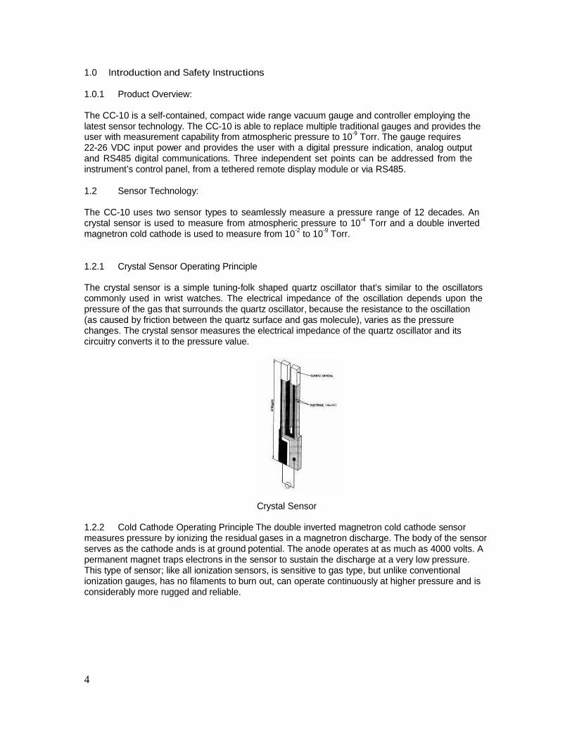
1.2.1 Crystal Sensor Operating Principle
The crystal sensor is a simple tuning-folk shaped quartz oscillator that’s similar to the oscillatorscommonly used in wrist watches. The electrical impedance of the oscillation depends upon thepressure of the gas that surrounds the quartz oscillator, because the resistance to the oscillation(as caused by friction between the quartz surface and gas molecule), varies as the pressurechanges. The crystal sensor measures the electrical impedance of the quartz oscillator and itscircuitry converts it to the pressure value.
Crystal Sensor
1.2.2 Cold Cathode Operating Principle The double inverted magnetron cold cathode sensormeasures pressure by ionizing the residual gases in a magnetron discharge. The body of the sensorserves as the cathode ands is at ground potential. The anode operates at as much as 4000 volts. Apermanent magnet traps electrons in the sensor to sustain the discharge at a very low pressure.This type of sensor; like all ionization sensors, is sensitive to gas type, but unlike conventionalionization gauges, has no filaments to burn out, can operate continuously at higher pressure and isconsiderably more rugged and reliable.
4
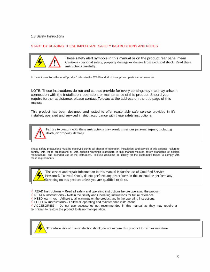
1.3 Safety Instructions
START BY READING THESE IMPORTANT SAFETY INSTRUCTIONS AND NOTES
These safety alert symbols in this manual or on the product rear panel meanCautions - personal safety, property damage or danger from electrical shock. Read theseinstructions carefully.
In these instructions the word “product” refers to the CC-10 and all of its approved parts and accessories.
NOTE: These instructions do not and cannot provide for every contingency that may arise inconnection with the installation, operation, or maintenance of this product. Should yourequire further assistance, please contact Televac at the address on the title page of thismanual.
This product has been designed and tested to offer reasonably safe service provided in it’sinstalled, operated and serviced in strict accordance with these safety instructions.
Failure to comply with these instructions may result in serious personal injury, includingdeath, or property damage.
These safety precautions must be observed during all phases of operation, installation, and service of this product. Failure tocomply with these precautions or with specific warnings elsewhere in this manual violates safety standards of design,manufacture, and intended use of the instrument. Televac disclaims all liability for the customer’s failure to comply withthese requirements.
The service and repair information in this manual is for the use of Qualified ServicePersonnel. To avoid shock, do not perform any procedures in this manual or perform anyServicing on this product unless you are qualified to do so.
READ Instructions – Read all safety and operating instructions before operating the product.RETAIN instructions – Retain the Safety and Operating Instructions for future reference.HEED warnings – Adhere to all warnings on the product and in the operating instructions.FOLLOW instructions – Follow all operating and maintenance instructions.ACCESORIES – Do not use accessories not recommended in this manual as they may require a
technician to restore the product to its normal operation.
To reduce risk of fire or electric shock, do not expose this product to rain or moisture.
5
Safety Instructions (cont.)
Objects and Liquid Entry – Never push objects of any kind into this product throughopenings as they may touch dangerous voltage points or short out parts that could result in afire or electric shock. Be careful not to spill liquid of any kind onto the products.
Do not substitute parts or modify instrument. Because of the danger on introducing additionalhazards, do not install substitute parts or perform any unauthorized modifications to theproduct. Return the product to Televac for service and repair to ensure that safety featuresare maintained. Do not use this product if it has unauthorized modifications.
6
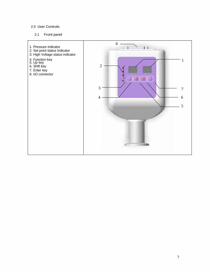
2.0 User Controls
2.1 Front panel
81. Pressure indicator2. Set point status Indicator3. High Voltage status indicator4. Function key 15. Up key6. Shift key 27. Enter key8. I/O connector
3 7
4 6
5
7
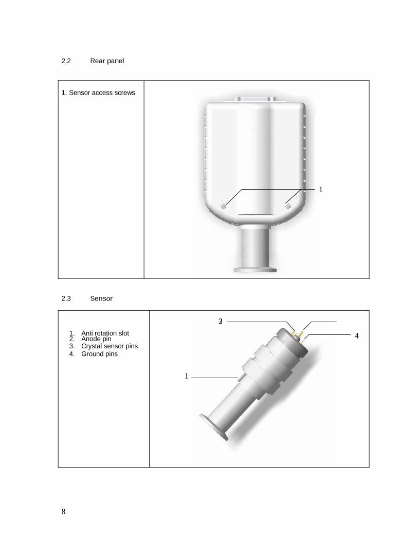
2.2 Rear panel
1. Sensor access screws
1
2.3 Sensor
231. Anti rotation slot 42. Anode pin3. Crystal sensor pins4. Ground pins
1
8
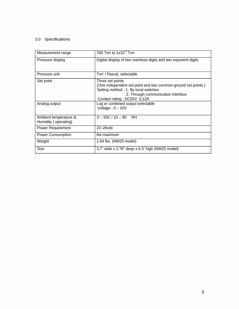
3.0 Specifications
Measurement range 760 Torr to 1x10⁻⁹ Torr
Pressure display Digital display of two mantissa digits and two exponent digits
Pressure unit Torr / Pascal, selectable
Set point Three set points(One independent set point and two common ground set points )Setting method : 1. By local switches
2. Through communication interfaceContact rating : DC50V 0.12A
Analog output Log or combined output selectableVoltage : 0 – 10V
Ambient temperature &Humidity ( operating)
0 – 50C / 10 – 90 RH
Power Requirement 22–26vdc
Power Consumption 8w maximumWeight 1.54 lbs. (NW25 model)
Size 3.7” wide x 2.78” deep x 6.3” high (NW25 model)
9
4.0 Operation
4.1 Starting the measurement
Connect D sub-connector to the instrument and supply power after installing CC-10 to thevacuum system and properly connecting necessary wires. When the power is supplied the unitruns an internal check program for several seconds then goes to measurement mode. Pressuredisplay will appear on the display.
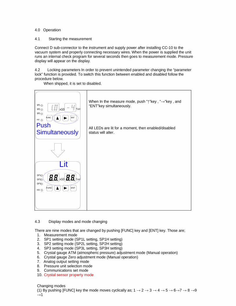
4.2 Locking parameters In order to prevent unintended parameter changing the “parameterlock” function is provided. To switch this function between enabled and disabled follow theprocedure below.
When shipped, it is set to disabled.
SP1
SP2
SP3
x10 Torr
When In the measure mode, push ”key , ”key , and“ENT”key simultaneously.
FUNCHV
ENT
PushSimultaneously
Lit
All LEDs are lit for a moment, then enabled/disabledstatus will alter.
SP1
SP2
SP3
HVFUNC
x10
ENT
Torr
4.3 Display modes and mode changing
There are nine modes that are changed by pushing [FUNC] key and [ENT] key. Those are;1. Measurement mode2. SP1 setting mode (SP1L setting, SP1H setting)3. SP2 setting mode (SP2L setting, SP2H setting)4. SP3 setting mode (SP3L setting, SP3H setting)5. Crystal gauge ATM (atmospheric pressure) adjustment mode (Manual operation)6. Crystal gauge Zero adjustment mode (Manual operation)7. Analog output setting mode8. Pressure unit selection mode9. Communications set mode10. Crystal sensor property mode
Changing modes(1) By pushing [FUNC] key the mode moves cyclically as; 1 2 3 4 5 7 8 9
1
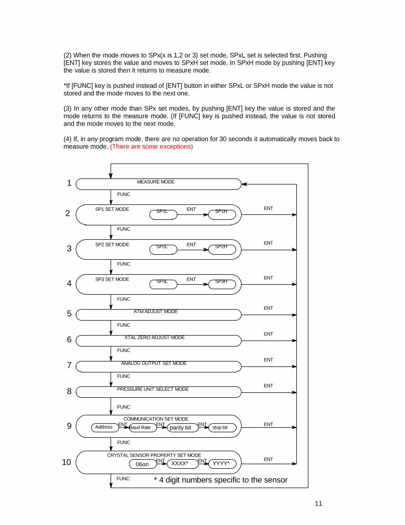
(2) When the mode moves to SPx(x is 1,2 or 3) set mode, SPxL set is selected first. Pushing[ENT] key stores the value and moves to SPxH set mode. In SPxH mode by pushing [ENT] keythe value is stored then it returns to measure mode.
*If [FUNC] key is pushed instead of [ENT] button in either SPxL or SPxH mode the value is notstored and the mode moves to the next one.
(3) In any other mode than SPx set modes, by pushing [ENT] key the value is stored and themode returns to the measure mode. (If [FUNC] key is pushed instead, the value is not storedand the mode moves to the next mode.
(4) If, in any program mode, there are no operation for 30 seconds it automatically moves back tomeasure mode. (There are some exceptions)
1
ENT
ENT
ENT
ENT
SP1L SP1H2ENT
FUNC
SP3HSP3L
SP2L SP2H
FUNC
ENT
ENT
ENT
FUNC
FUNC
4
3
ENT
6
ENT
FUNC
FUNC
FUNC
8
ATM ADJUST MODE
XTAL ZERO ADJUST MODE
ANALOG OUTPUT SET MODE
PRESSURE UNIT SELECT MODE
7
5
FUNC
FUNC
COMMUNICATION SET MODEAddress Baud Rate parity bit stop bitENT ENT ENT ENT9
MEASURE MODE
SP1 SET MODE
SP2 SET MODE
SP3 SET MODE
FUNC
CRYSTAL SENSOR PROPERTY SET MODE
06on XXXX* YYYY*ENT ENT10 ENT
* 4 digit numbers specific to the sensor
11
4.4 Set Point
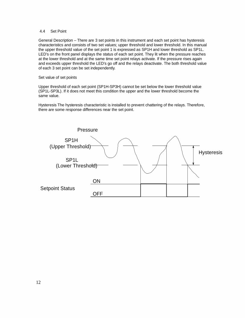
General Description – There are 3 set points in this instrument and each set point has hysteresischaracteristics and consists of two set values; upper threshold and lower threshold. In this manualthe upper threshold value of the set point 1 is expressed as SP1H and lower threshold as SP1L.LED’s on the front panel displays the status of each set point. They lit when the pressure reachesat the lower threshold and at the same time set point relays activate. If the pressure rises againand exceeds upper threshold the LED’s go off and the relays deactivate. The both threshold valueof each 3 set point can be set independently.
Set value of set points
Upper threshold of each set point (SP1H-SP3H) cannot be set below the lower threshold value(SP1L-SP3L). If it does not meet this condition the upper and the lower threshold become thesame value.
Hysteresis The hysteresis characteristic is installed to prevent chattering of the relays. Therefore,there are some response differences near the set point.
Pressure
SP1H(Upper Threshold)
SP1L(Lower Threshold)
Hysteresis
Setpoint StatusON
OFF
12
4.5 Explanation of each mode
Measurement Mode
SP1
SP2
SP3
HVFUNC
x10 Pa
ENT
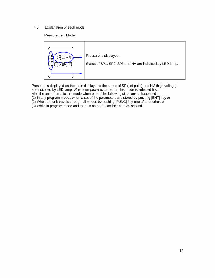
Pressure is displayed.
Status of SP1, SP2, SP3 and HV are indicated by LED lamp.
Pressure is displayed on the main display and the status of SP (set point) and HV (high voltage)are indicated by LED lamp. Whenever power is turned on this mode is selected first.Also the unit returns to this mode when one of the following situations is happened.(1) In any program modes when a set of the parameters are stored by pushing [ENT] key or(2) When the unit travels through all modes by pushing [FUNC] key one after another. or(3) While in program mode and there is no operation for about 30 second.
13
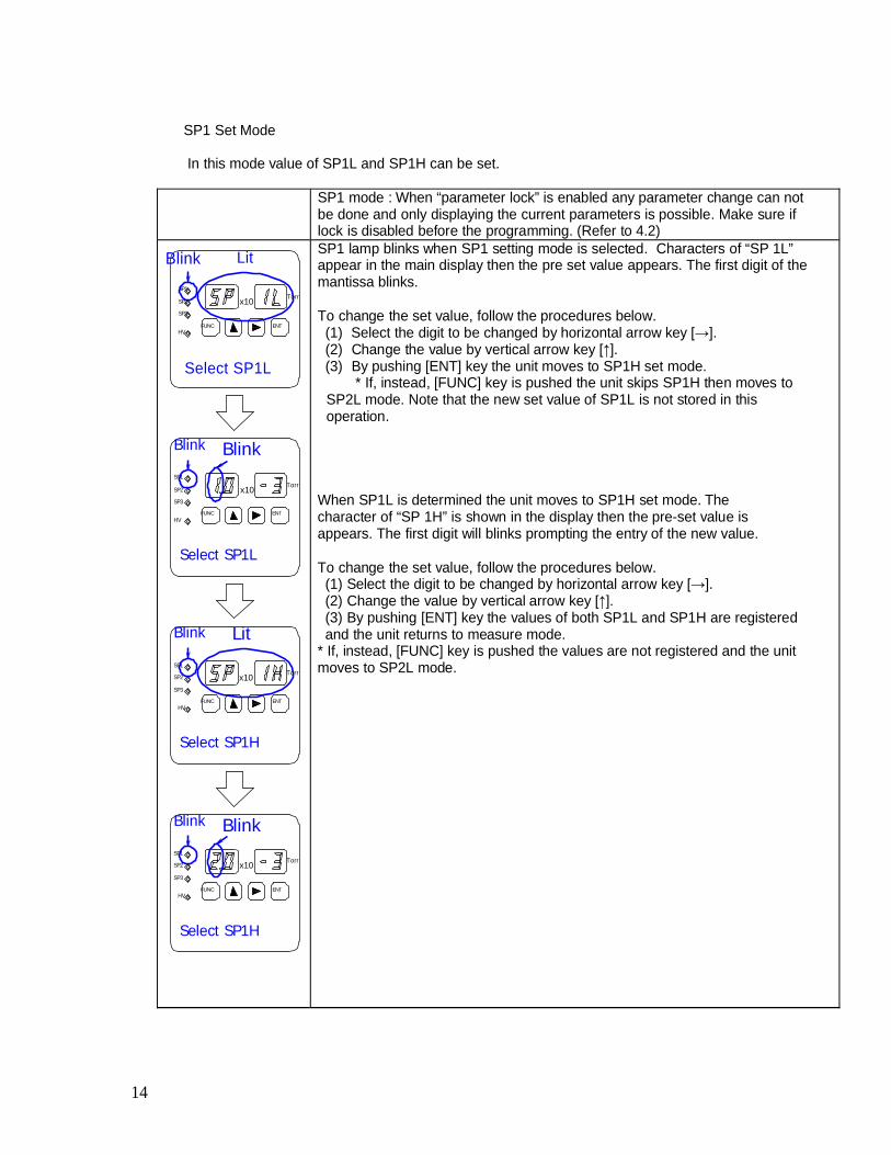
SP1 Set Mode
In this mode value of SP1L and SP1H can be set.
BlinkSP1
SP2
SP3
FUNCHV
Lit
x10
ENT
Torr
SP1 mode : When “parameter lock” is enabled any parameter change can notbe done and only displaying the current parameters is possible. Make sure iflock is disabled before the programming. (Refer to 4.2)SP1 lamp blinks when SP1 setting mode is selected. Characters of “SP 1L”appear in the main display then the pre set value appears. The first digit of themantissa blinks.
To change the set value, follow the procedures below.(1) Select the digit to be changed by horizontal arrow key ].(2) Change the value by vertical arrow key ].
Select SP1L (3) By pushing [ENT] key the unit moves to SP1H set mode.* If, instead, [FUNC] key is pushed the unit skips SP1H then moves to
SP2L mode. Note that the new set value of SP1L is not stored in thisoperation.
Blink BlinkSP1
SP2
SP3
HV
x10
FUNC ENT
Torr
When SP1L is determined the unit moves to SP1H set mode. Thecharacter of “SP 1H” is shown in the display then the pre-set value isappears. The first digit will blinks prompting the entry of the new value.
Select SP1LTo change the set value, follow the procedures below.(1) Select the digit to be changed by horizontal arrow key ].(2) Change the value by vertical arrow key ].(3) By pushing [ENT] key the values of both SP1L and SP1H are registered
Blink
SP1
SP2
SP3
Lit
x10Torr
and the unit returns to measure mode.* If, instead, [FUNC] key is pushed the values are not registered and the unitmoves to SP2L mode.
FUNCHV
ENT
Select SP1H
Blink BlinkSP1
SP2
SP3
x10Torr
FUNCHV
ENT
Select SP1H
14
SP2 ,SP3 Setting Mode The settings of SP2L, SP2H, SP3L and SP3H are possible. Followthe same procedure as SP1L/SP1H setting.
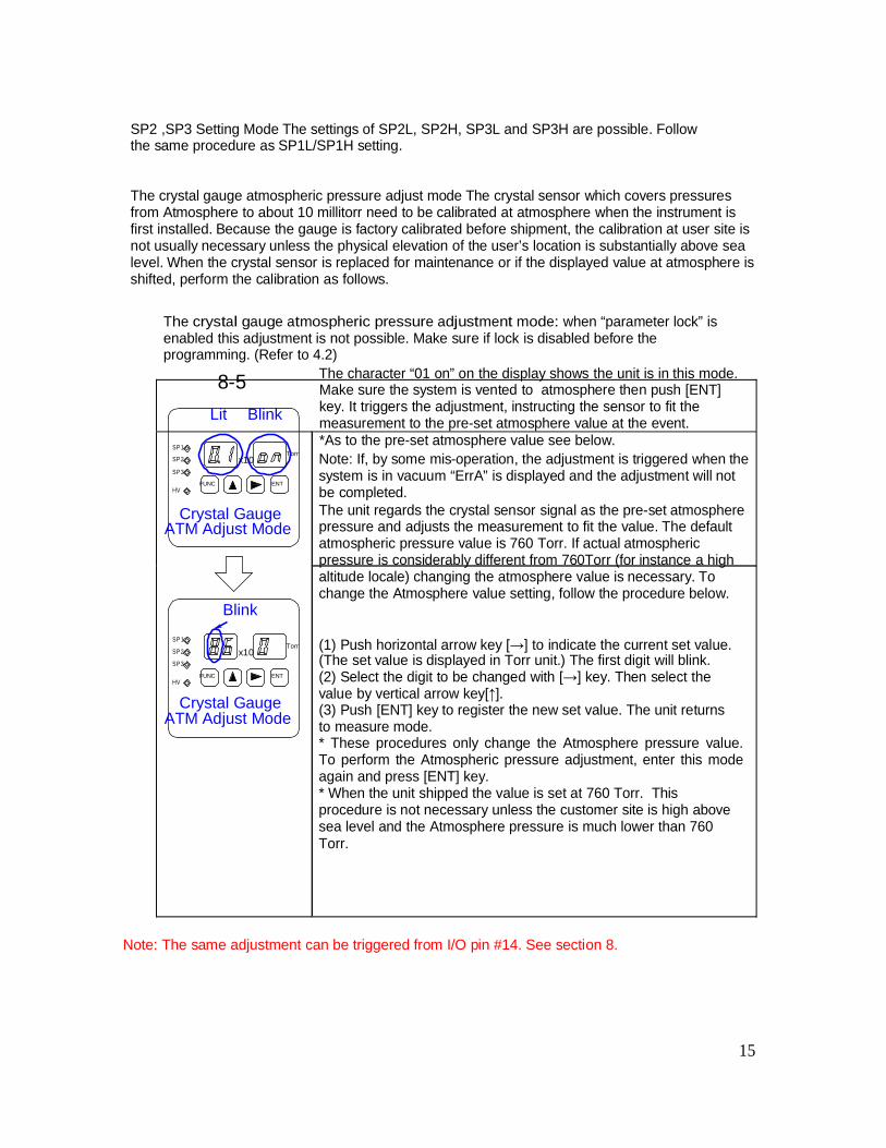
The crystal gauge atmospheric pressure adjust mode The crystal sensor which covers pressuresfrom Atmosphere to about 10 millitorr need to be calibrated at atmosphere when the instrument isfirst installed. Because the gauge is factory calibrated before shipment, the calibration at user site isnot usually necessary unless the physical elevation of the user’s location is substantially above sealevel. When the crystal sensor is replaced for maintenance or if the displayed value at atmosphere isshifted, perform the calibration as follows.
The crystal gauge atmospheric pressure adjustment mode: when “parameter lock” isenabled this adjustment is not possible. Make sure if lock is disabled before theprogramming. (Refer to 4.2)
The character “01 on” on the display shows the unit is in this mode.
SP1
8-5Lit Blink
Make sure the system is vented to atmosphere then push [ENT]key. It triggers the adjustment, instructing the sensor to fit themeasurement to the pre-set atmosphere value at the event.*As to the pre-set atmosphere value see below.
SP2
SP3
HVFUNC
x10
ENT
Torr Note: If, by some mis-operation, the adjustment is triggered when thesystem is in vacuum “ErrA” is displayed and the adjustment will notbe completed.
Crystal GaugeATM Adjust Mode
BlinkSP1
The unit regards the crystal sensor signal as the pre-set atmospherepressure and adjusts the measurement to fit the value. The defaultatmospheric pressure value is 760 Torr. If actual atmosphericpressure is considerably different from 760Torr (for instance a highaltitude locale) changing the atmosphere value is necessary. Tochange the Atmosphere value setting, follow the procedure below.
SP2
SP3
HVFUNC
x10
ENT
Torr (1) Push horizontal arrow key ] to indicate the current set value.(The set value is displayed in Torr unit.) The first digit will blink.(2) Select the digit to be changed with ] key. Then select the
Crystal GaugeATM Adjust Mode
value by vertical arrow key[ ].(3) Push [ENT] key to register the new set value. The unit returnsto measure mode.* These procedures only change the Atmosphere pressure value.To perform the Atmospheric pressure adjustment, enter this modeagain and press [ENT] key.* When the unit shipped the value is set at 760 Torr. Thisprocedure is not necessary unless the customer site is high abovesea level and the Atmosphere pressure is much lower than 760Torr.
Note: The same adjustment can be triggered from I/O pin #14. See section 8.
15
Crystal gauge zero adjustment mode In this mode, it is possible to manually make a zeroadjustment of the crystal gauge. Usually this adjustment is not necessary, because it is performedautomatically every time the pressure reaches 3.0 x 10⁻³ Torr. When the crystal sensor isreplaced for maintenance or if the zero has shifted, a manual zero adjustment might be required.
Crystal gauge Zero adjustment mode: When “parameter lock” is enabled this adjustment isnot possible. Make sure if lock is disabled before the programming. (Refer to 4.2)The character “02 on” on the display shows the unit is in this mode. Pushing [ENT] keytriggers the zero adjustment instructing the sensor to fit the measurement to zero at theevent.
Note: The same adjustment can be triggered from I/O pin #6. See section 8.
Analog output setting mode. The analog output can be selected from the Log output mode orthe combined output mode. When the Log output is selected, it is necessary to set the widthvoltage of one decade and the full scale voltage. If the optional display unit DS-10 is used, theoutput mode will have to be set accordingly.
In this section only the operation will be explained. A detail of the analog output is described inthe next section.
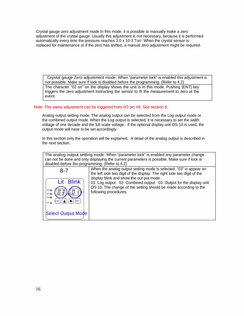
The analog output setting mode: When “parameter lock” is enabled any parameter changecan not be done and only displaying the current parameters is possible. Make sure if lock isdisabled before the programming. (Refer to 4.2)
8-7 When the analog output setting mode is selected, “03” is appear onthe left side two digit of the display. The right side two digit of thedisplay blink and show the out put mode.
SP1
SP2
SP3
HV
Lit
FUNC
BlinkTorr
x10
ENT
01: Log output 02: Combined output 03: Output for the display unitDS-10. The change of the setting should be made according to thefollowing procedures.
Select Output Mode
16
SP1
SP2
SP3
HV
Lit
FUNC
Blink
x10
ENT
Torr
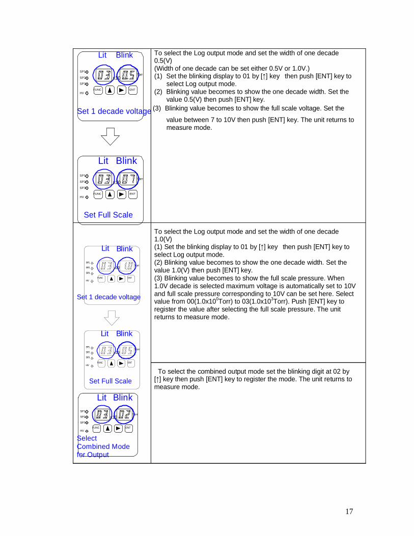
To select the Log output mode and set the width of one decade0.5(V)(Width of one decade can be set either 0.5V or 1.0V.)(1) Set the blinking display to 01 by ] key then push [ENT] key to
select Log output mode.(2) Blinking value becomes to show the one decade width. Set the
value 0.5(V) then push [ENT] key.
Set 1 decade voltage (3) Blinking value becomes to show the full scale voltage. Set the
value between 7 to 10V then push [ENT] key. The unit returns tomeasure mode.
Lit BlinkSP1
SP2
SP3
HVFUNC
x10
ENT
Torr
Set Full Scale
SP1
SP2
SP3
HV
Lit
FUNC
Blink
x10
ENT
Torr
To select the Log output mode and set the width of one decade1.0(V)(1) Set the blinking display to 01 by ] key then push [ENT] key toselect Log output mode.(2) Blinking value becomes to show the one decade width. Set thevalue 1.0(V) then push [ENT] key.(3) Blinking value becomes to show the full scale pressure. When1.0V decade is selected maximum voltage is automatically set to 10Vand full scale pressure corresponding to 10V can be set here. SelectSet 1 decade voltage value from 00(1.0x100Torr) to 03(1.0x10³Torr). Push [ENT] key toregister the value after selecting the full scale pressure. The unitreturns to measure mode.
Lit BlinkSP1
SP2
SP3
x10Torr
FUNCHV
ENT
To select the combined output mode set the blinking digit at 02 bySet Full Scale ] key then push [ENT] key to register the mode. The unit returns to
measure mode.
Lit BlinkSP1
SP2
SP3
HVFUNC
x10
ENT
Torr
SelectCombined Modefor Output
17
SP1
SP2
SP3
Lit Blink
x10Torr
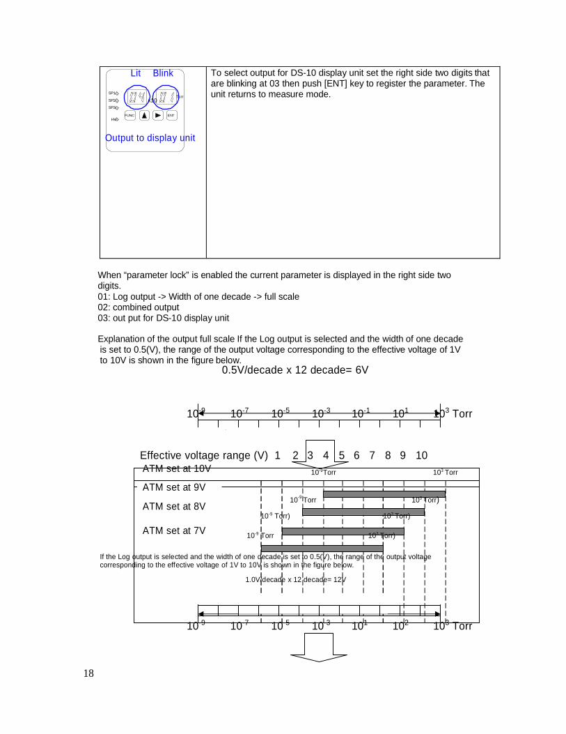
To select output for DS-10 display unit set the right side two digits thatare blinking at 03 then push [ENT] key to register the parameter. Theunit returns to measure mode.
FUNCHV
ENT
Output to display unit
When “parameter lock” is enabled the current parameter is displayed in the right side twodigits.01: Log output -> Width of one decade -> full scale02: combined output03: out put for DS-10 display unit
Explanation of the output full scale If the Log output is selected and the width of one decadeis set to 0.5(V), the range of the output voltage corresponding to the effective voltage of 1Vto 10V is shown in the figure below.
0.5V/decade x 12 decade= 6V
10-9 10-7 10-5 10-3 10-1 101 103 Torr
Effective voltage range (V) 1 2 3 4 5 6 7 8 9 10ATM set at 10V
ATM set at 9V
ATM set at 8V
ATM set at 7V
10-9Torr 103 Torr
10-9 Torr 103 Torr)
10-9 Torr) 103 Torr)
10-9 Torr 103 Torr)
If the Log output is selected and the width of one decade is set to 0.5(V), the range of the output voltagecorresponding to the effective voltage of 1V to 10V is shown in the figure below.
1.0V/decade x 12 decade= 12V
10-9 10-7 10-5 10-3 101 102 103 Torr
18
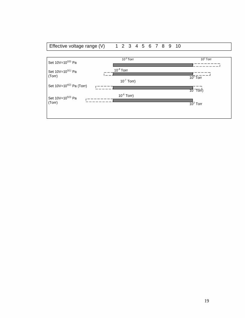
Effective voltage range (V) 1 2 3 4 5 6 7 8 9 10
Set 10V=102(0) Pa
Set 10V=103(1) Pa(Torr)
Set 10V=104(2) Pa (Torr)
Set 10V=105(3) Pa(Torr)
10-9 Torr
10-8 Torr
10-7 Torr)
10-6 Torr)
101 Torr
100 Torr
10 Torr)
103 Torr
19
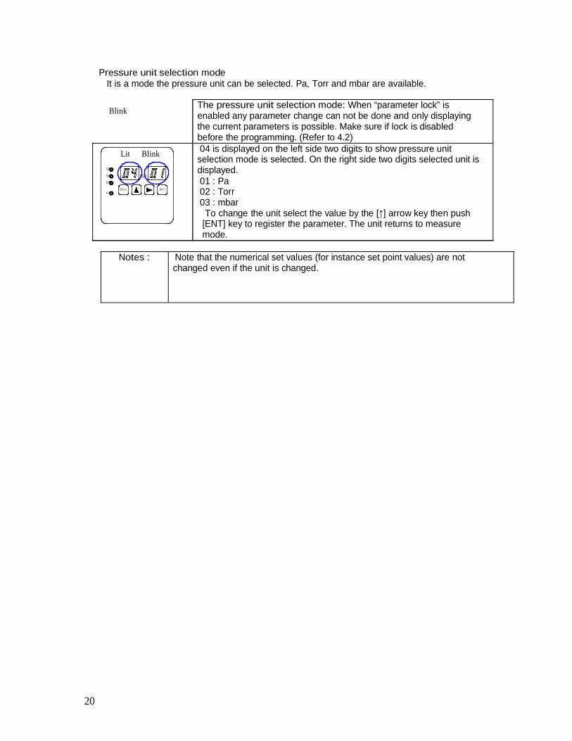
Pressure unit selection modeIt is a mode the pressure unit can be selected. Pa, Torr and mbar are available.
Blink
LitSP1
SP2
SP3
FU N CH V
Blink
x10
EN T
The pressure unit selection mode: When “parameter lock” isenabled any parameter change can not be done and only displayingthe current parameters is possible. Make sure if lock is disabledbefore the programming. (Refer to 4.2)04 is displayed on the left side two digits to show pressure unitselection mode is selected. On the right side two digits selected unit isdisplayed.01 : Pa02 : Torr03 : mbar
To change the unit select the value by the ] arrow key then push[ENT] key to register the parameter. The unit returns to measuremode.
Notes : Note that the numerical set values (for instance set point values) are notchanged even if the unit is changed.
20
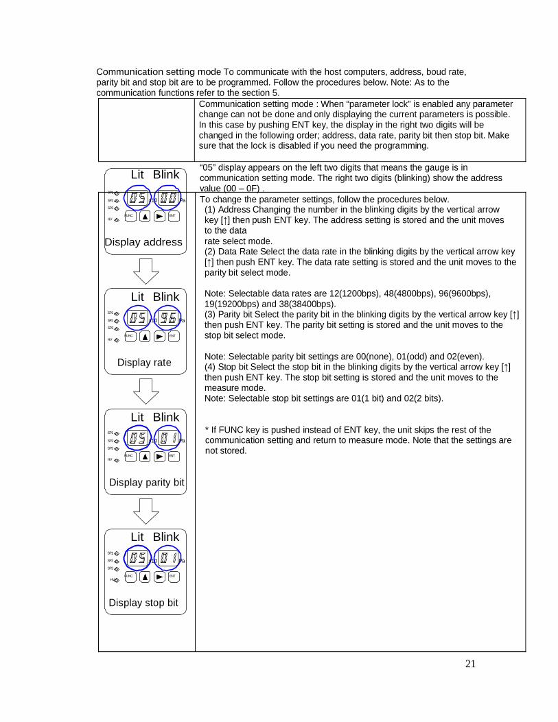
Communication setting mode To communicate with the host computers, address, boud rate,parity bit and stop bit are to be programmed. Follow the procedures below. Note: As to thecommunication functions refer to the section 5.
Communication setting mode : When “parameter lock” is enabled any parameterchange can not be done and only displaying the current parameters is possible.In this case by pushing ENT key, the display in the right two digits will bechanged in the following order; address, data rate, parity bit then stop bit. Makesure that the lock is disabled if you need the programming.
SP1
Lit Blink “05” display appears on the left two digits that means the gauge is incommunication setting mode. The right two digits (blinking) show the addressvalue (00 – 0F) .
SP2
SP3
HVFUNC
x10 Pa
ENT
To change the parameter settings, follow the procedures below.(1) Address Changing the number in the blinking digits by the vertical arrowkey ] then push ENT key. The address setting is stored and the unit movesto the data
Display address rate select mode.(2) Data Rate Select the data rate in the blinking digits by the vertical arrow key
] then push ENT key. The data rate setting is stored and the unit moves to theparity bit select mode.
SP1
SP2
SP3
HV
Lit
FUNC
Blink
x10 Pa
ENT
Note: Selectable data rates are 12(1200bps), 48(4800bps), 96(9600bps),19(19200bps) and 38(38400bps).(3) Parity bit Select the parity bit in the blinking digits by the vertical arrow key ]then push ENT key. The parity bit setting is stored and the unit moves to thestop bit select mode.
Display rate Note: Selectable parity bit settings are 00(none), 01(odd) and 02(even).(4) Stop bit Select the stop bit in the blinking digits by the vertical arrow key ]then push ENT key. The stop bit setting is stored and the unit moves to themeasure mode.Note: Selectable stop bit settings are 01(1 bit) and 02(2 bits).
SP1
Lit Blink* If FUNC key is pushed instead of ENT key, the unit skips the rest of the
SP2
SP3
HV
x10 Pa
FUNC ENT
communication setting and return to measure mode. Note that the settings arenot stored.
Display parity bit
Lit BlinkSP1
SP2
SP3
x10 Pa
FUNCHV
ENT
Display stop bit
21
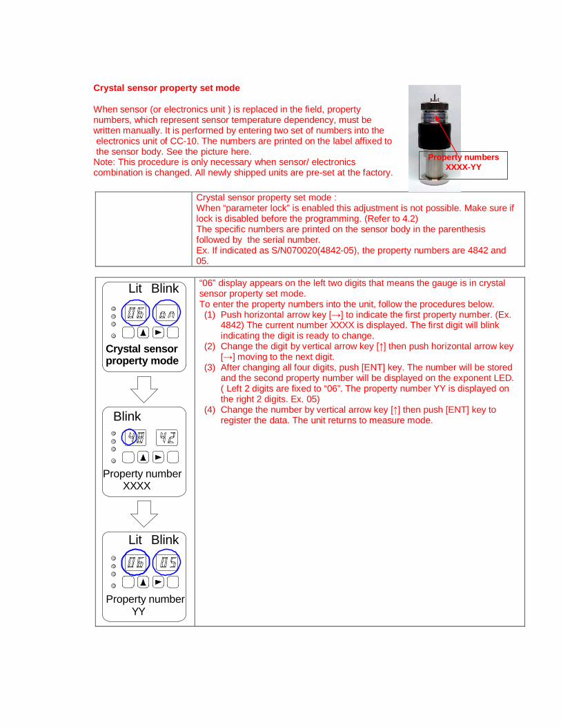
Crystal sensor property set mode
When sensor (or electronics unit ) is replaced in the field, propertynumbers, which represent sensor temperature dependency, must bewritten manually. It is performed by entering two set of numbers into the electronics unit of CC-10. The numbers are printed on the label affixed to the sensor body. See the picture here.Note: This procedure is only necessary when sensor/ electronicscombination is changed. All newly shipped units are pre-set at the factory.
Crystal sensor property set mode :When “parameter lock” is enabled this adjustment is not possible. Make sure iflock is disabled before the programming. (Refer to 4.2)The specific numbers are printed on the sensor body in the parenthesisfollowed by the serial number.Ex. If indicated as S/N070020(4842-05), the property numbers are 4842 and05.
BlinkLit
Property number XXXX
Property number YY
BlinkLit
Blink
Crystal sensorproperty mode
“06” display appears on the left two digits that means the gauge is in crystalsensor property set mode.To enter the property numbers into the unit, follow the procedures below.(1) Push horizontal arrow key [ ] to indicate the first property number. (Ex.
4842) The current number XXXX is displayed. The first digit will blinkindicating the digit is ready to change.
(2) Change the digit by vertical arrow key [ ] then push horizontal arrow key] moving to the next digit.
(3) After changing all four digits, push [ENT] key. The number will be storedand the second property number will be displayed on the exponent LED.( Left 2 digits are fixed to “06”. The property number YY is displayed onthe right 2 digits. Ex. 05)
(4) Change the number by vertical arrow key [ ] then push [ENT] key toregister the data. The unit returns to measure mode.
Property numbersXXXX-YY
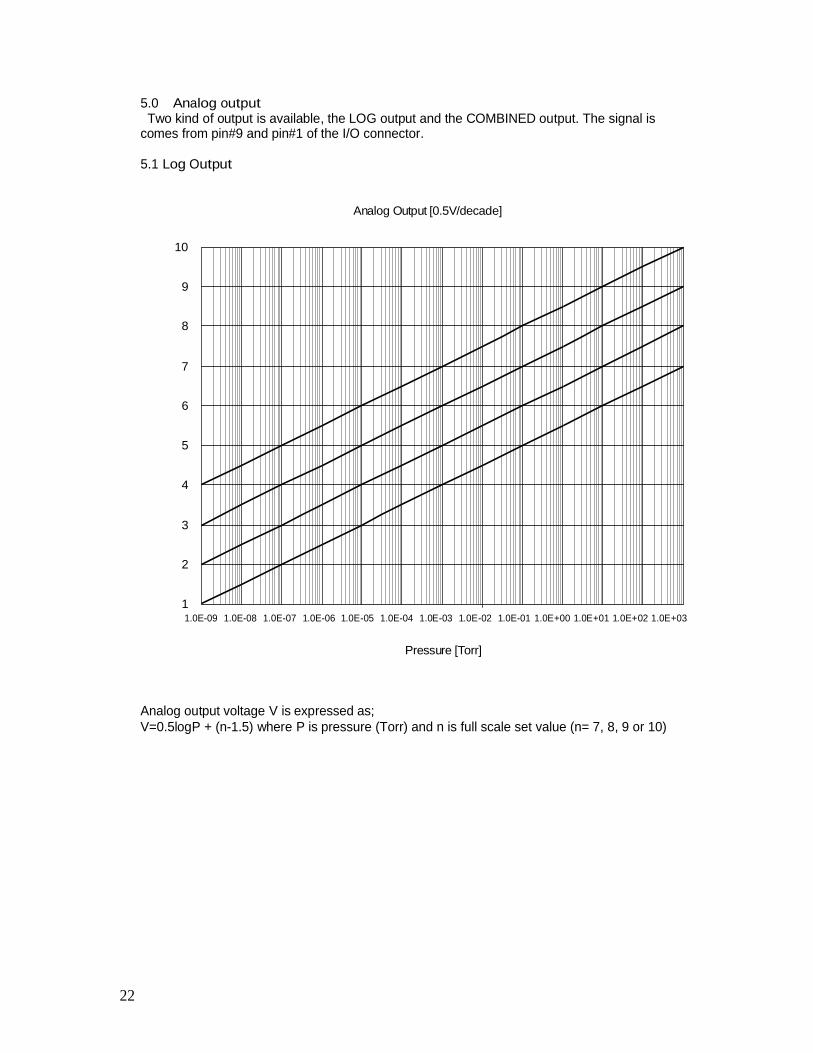
5.0 Analog output Two kind of output is available, the LOG output and the COMBINED output. The signal iscomes from pin#9 and pin#1 of the I/O connector.
5.1 Log Output
Analog Output [0.5V/decade]
10
9
8
7
6
5
4
3
2
11.0E-09 1.0E-08 1.0E-07 1.0E-06 1.0E-05 1.0E-04 1.0E-03 1.0E-02 1.0E-01 1.0E+00 1.0E+01 1.0E+02 1.0E+03
Pressure [Torr]
Analog output voltage V is expressed as;V=0.5logP + (n-1.5) where P is pressure (Torr) and n is full scale set value (n= 7, 8, 9 or 10)
22
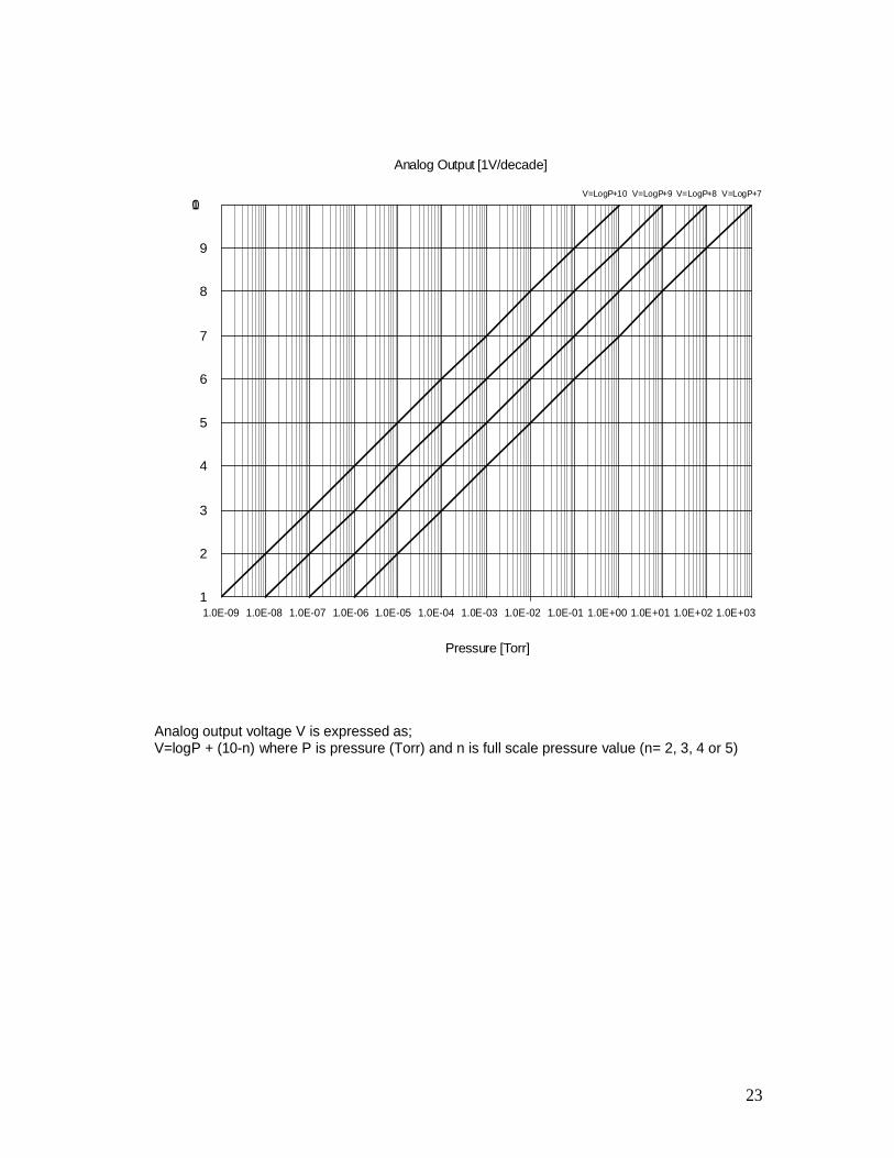
Analog Output [1V/decade]
V=LogP+10 V=LogP+9 V=LogP+8 V=LogP+701
9
8
7
6
5
4
3
2
11.0E-09 1.0E-08 1.0E-07 1.0E-06 1.0E-05 1.0E-04 1.0E-03 1.0E-02 1.0E-01 1.0E+00 1.0E+01 1.0E+02 1.0E+03
Pressure [Torr]
Analog output voltage V is expressed as;V=logP + (10-n) where P is pressure (Torr) and n is full scale pressure value (n= 2, 3, 4 or 5)
23
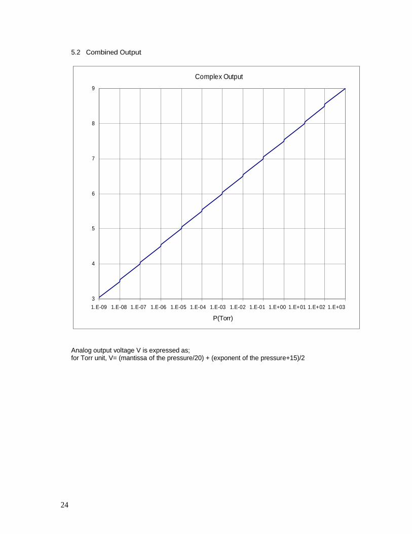
5.2 Combined Output
Complex Output9
8
7
6
5
4
31.E-09 1.E-08 1.E-07 1.E-06 1.E-05 1.E-04 1.E-03 1.E-02 1.E-01 1.E+00 1.E+01 1.E+02 1.E+03
P(Torr)
Analog output voltage V is expressed as;for Torr unit, V= (mantissa of the pressure/20) + (exponent of the pressure+15)/2
24
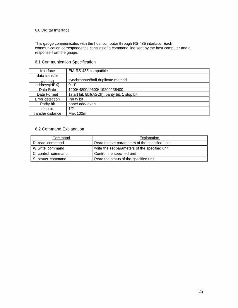
6.0 Digital Interface
This gauge communicates with the host computer through RS-485 interface. Eachcommunication correspondence consists of a command line sent by the host computer and aresponse from the gauge.
6.1 Communication Specification
Interface EIA RS-485 compatibledata transfer
method synchronous/half duplicate methodaddress(HEX) 0 - F
Data Rate 1200/ 4800/ 9600/ 19200/ 38400Data Format 1start bit, 8bit(ASCII), parity bit, 1 stop bit
Error detection Parity bitParity bit none/ odd/ evenstop bit 1/2
transfer distance Max 100m
6.2 Command Explanation
Command ExplanationR read command Read the set parameters of the specified unitW write command write the set parameters of the specified unitC control command Control the specified unitS status command Read the status of the specified unit
25
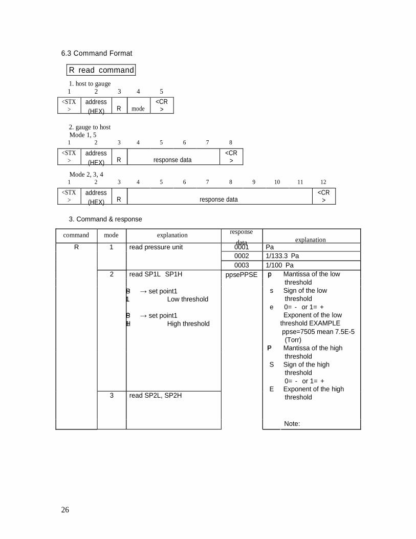
6.3 Command Format
R read command1. host to gauge1 2 3 4 5
<STX>
address(HEX) R mode
<CR>
2. gauge to hostMode 1, 5
1 2 3 4 5 6 7 8
<STX>
address(HEX) R response data
<CR>
Mode 2, 3, 41 2 3 4 5 6 7 8 9 10 11 12
<STX>
address(HEX) R response data
<CR>
3. Command & response
command mode explanation responsedata explanation
R 1 read pressure unit 0001 Pa0002 1/133.3 Pa0003 1/100 Pa
2 read SP1L SP1H ppsePPSE pp Mantissa of the lowthreshold
PS set point1L1 Low threshold
PS set point1H1 High threshold
3 read SP2L, SP2H
s Sign of the lowthreshold
e 0= - or 1= +Exponent of the low
threshold EXAMPLEppse=7505 mean 7.5E-5(Torr)
PP Mantissa of the highthreshold
S Sign of the highthreshold0= - or 1= +
E Exponent of the highthreshold
Note:
26
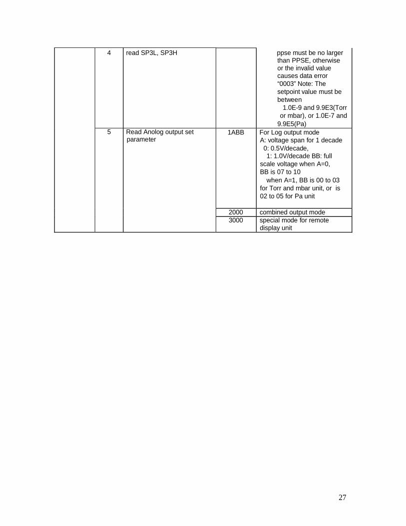
4 read SP3L, SP3H ppse must be no largerthan PPSE, otherwiseor the invalid valuecauses data error“0003” Note: Thesetpoint value must bebetween
1.0E-9 and 9.9E3(Torror mbar), or 1.0E-7 and
9.9E5(Pa)5 Read Anolog output set
parameter1ABB For Log output mode
A: voltage span for 1 decade0: 0.5V/decade,1: 1.0V/decade BB: full
scale voltage when A=0,BB is 07 to 10
when A=1, BB is 00 to 03for Torr and mbar unit, or is02 to 05 for Pa unit
2000 combined output mode3000 special mode for remote
display unit
27
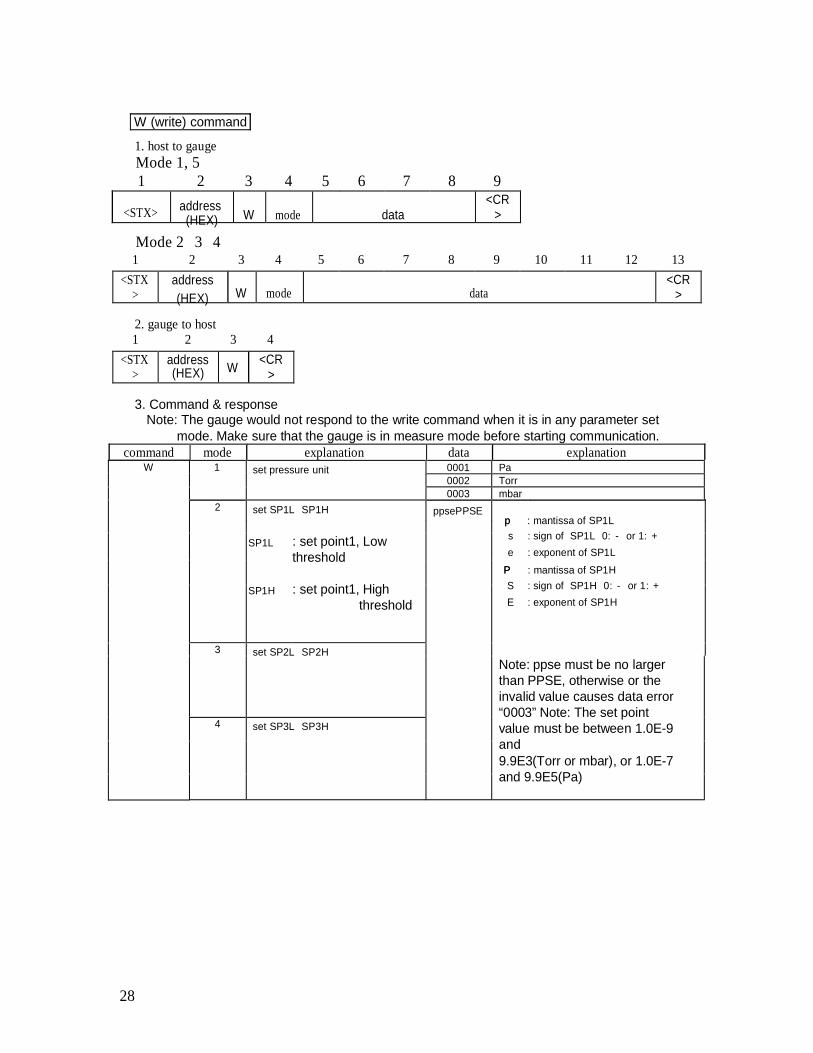
W (write) command
1. host to gaugeMode 1, 51 2 3 4 5 6 7 8 9
<STX> address(HEX) W mode data
Mode 2 3 4
<CR>
1 2 3 4 5 6 7 8 9 10 11 12 13<STX
>address(HEX) W mode data
<CR>
2. gauge to host1 2 3 4
<STX>
address(HEX) W <CR
>
3. Command & responseNote: The gauge would not respond to the write command when it is in any parameter set
mode. Make sure that the gauge is in measure mode before starting communication.command mode explanation data explanation
W 1 set pressure unit 0001 Pa0002 Torr0003 mbar
2 set SP1L SP1H ppsePPSEpp : mantissa of SP1L
SP1L
SP1H
: set point1, Lowthreshold
: set point1, Highthreshold
s : sign of SP1L 0: - or 1: +e : exponent of SP1L
PP : mantissa of SP1HS : sign of SP1H 0: - or 1: +E : exponent of SP1H
3 set SP2L SP2H
4 set SP3L SP3H
Note: ppse must be no largerthan PPSE, otherwise or theinvalid value causes data error“0003” Note: The set pointvalue must be between 1.0E-9and9.9E3(Torr or mbar), or 1.0E-7and 9.9E5(Pa)
28
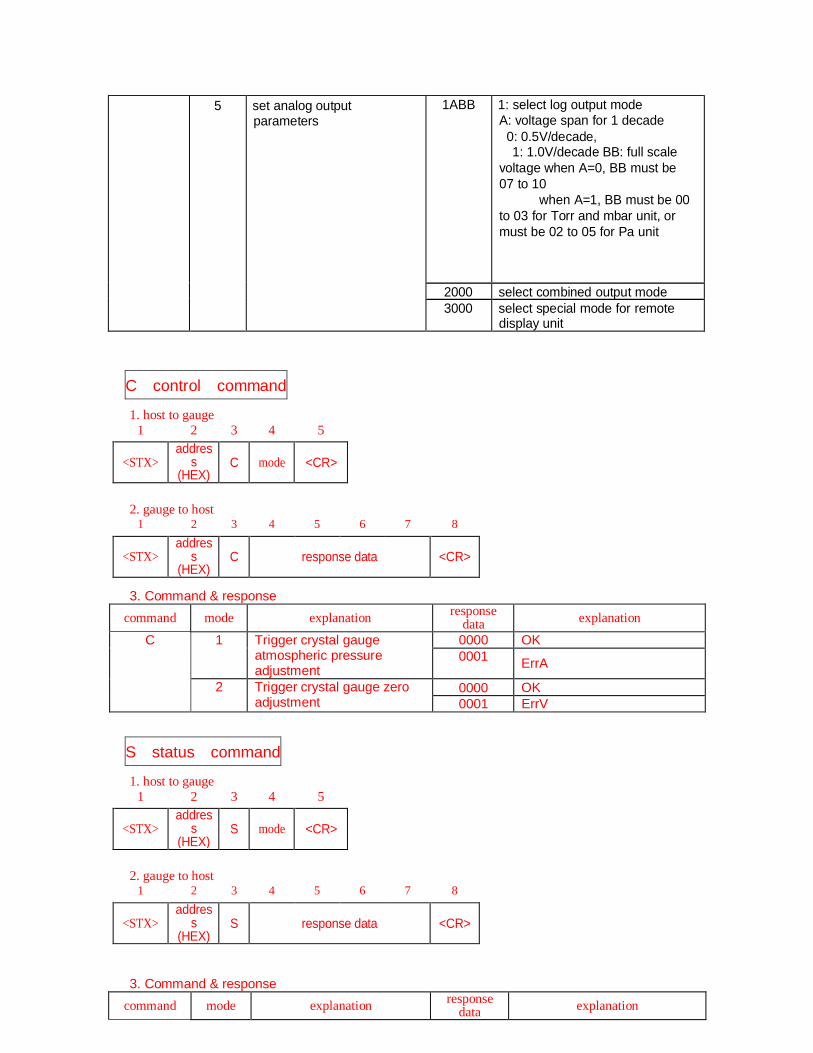
5 set analog outputparameters
1ABB 1: select log output modeA: voltage span for 1 decade
0: 0.5V/decade,1: 1.0V/decade BB: full scale
voltage when A=0, BB must be07 to 10
when A=1, BB must be 00to 03 for Torr and mbar unit, ormust be 02 to 05 for Pa unit
2000 select combined output mode3000 select special mode for remote
display unit
C control command
1. host to gauge1 2 3 4 5
<STX>addres
s(HEX)
C mode <CR>
2. gauge to host1 2 3 4 5 6 7 8
<STX>addres
s(HEX)
C response data <CR>
3. Command & responsecommand mode explanation response
data explanation
C 1 Trigger crystal gaugeatmospheric pressureadjustment
0000 OK0001 ErrA
2 Trigger crystal gauge zeroadjustment
0000 OK0001 ErrV
S status command
1. host to gauge1 2 3 4 5
<STX>addres
s(HEX)
S mode <CR>
2. gauge to host1 2 3 4 5 6 7 8
<STX>addres
s(HEX)
S response data <CR>
3. Command & responsecommand mode explanation response
data explanation
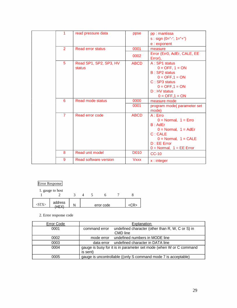
1 read pressure data ppse pp : mantissas : sign (0=”-“, 1=”+”)e : exponent
2 Read error status 0001 measure
0002 Error (Err0, AdEr, CALE, EEError),
5 Read SP1, SP2, SP3, HVstatus
ABCD A : SP1 status0 = OFF, 1 = ON
B : SP2 status0 = OFF,1 = ON
C : SP3 status0 = OFF,1 = ON
D : HV status0 = OFF,1 = ON
6 Read mode status 0000 measure mode0001 program mode( parameter set
mode)7 Read error code ABCD A : Erro
0 = Normal, 1 = ErroB : AdEr
0 = Normal, 1 = AdErC : CALE
0 = Normal, 1 = CALED : EE Error0 = Normal, 1 = EE Error
8 Read unit model D010 CC-109 Read software version Vxxx x : integer
Error Response
1. gauge to host1 2 3 4 5 6 7 8
<STX> address(HEX) N error code <CR>
2. Error response code
Error Code Explanation0001 command error undefined character (other than R, W, C or S) in
CMD line0002 mode error undefined numbers in MODE line0003 data error undefined character in DATA line0004 gauge is busy for it is in parameter set mode (when W or C command
is sent)0005 gauge is uncontrollable ((only S command mode 7 is acceptable)
29
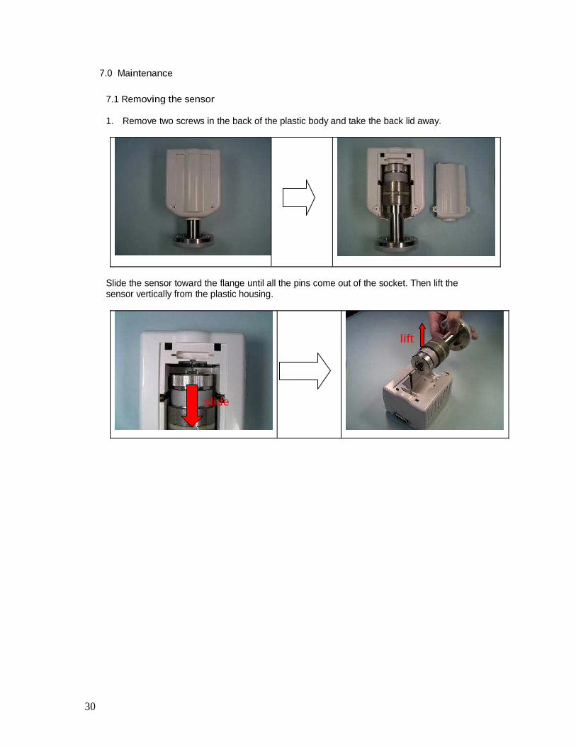
7.0 Maintenance
7.1 Removing the sensor
1. Remove two screws in the back of the plastic body and take the back lid away.
Slide the sensor toward the flange until all the pins come out of the socket. Then lift thesensor vertically from the plastic housing.
lift
slide
30
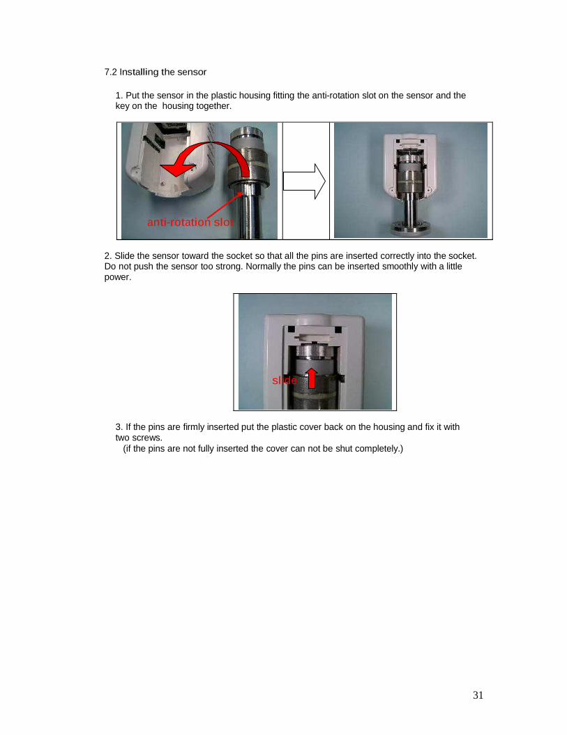
7.2 Installing the sensor
1. Put the sensor in the plastic housing fitting the anti-rotation slot on the sensor and thekey on the housing together.
anti-rotation slot
2. Slide the sensor toward the socket so that all the pins are inserted correctly into the socket.Do not push the sensor too strong. Normally the pins can be inserted smoothly with a littlepower.
slide
3. If the pins are firmly inserted put the plastic cover back on the housing and fix it withtwo screws.
(if the pins are not fully inserted the cover can not be shut completely.)
31
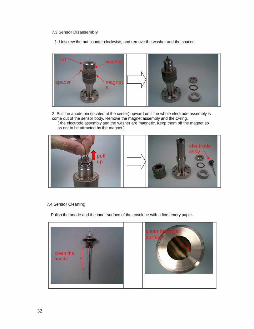
7.3 Sensor Disassembly
1. Unscrew the nut counter clockwise, and remove the washer and the spacer.
nut washer
spacer magnets
2. Pull the anode pin (located at the center) upward until the whole electrode assembly iscome out of the sensor body. Remove the magnet assembly and the O-ring.
( the electrode assembly and the washer are magnetic. Keep them off the magnet soas not to be attracted by the magnet.)
pullup
electrodeassy
7.4 Sensor Cleaning
Polish the anode and the inner surface of the envelope with a fine emery paper.
clean the innersurface
clean theanode
32
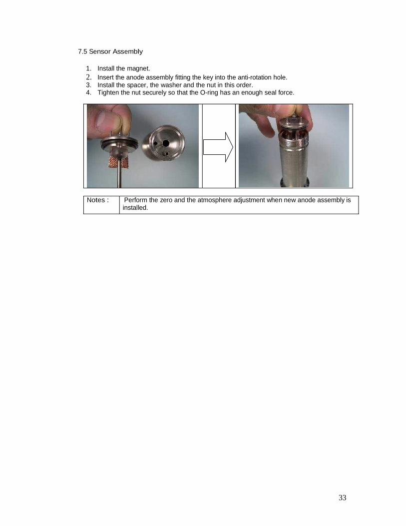
7.5 Sensor Assembly
1. Install the magnet.2. Insert the anode assembly fitting the key into the anti-rotation hole.3. Install the spacer, the washer and the nut in this order.4. Tighten the nut securely so that the O-ring has an enough seal force.
Notes : Perform the zero and the atmosphere adjustment when new anode assembly isinstalled.
33
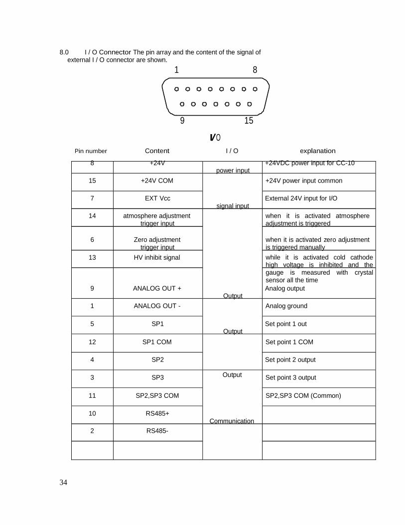
8.0 I / O Connector The pin array and the content of the signal ofexternal I / O connector are shown.
1 8
9 15
I/OPin number Content I / O explanation
8 +24V +24VDC power input for CC-10power input
15 +24V COM +24V power input common
7 EXT Vcc External 24V input for I/Osignal input
14 atmosphere adjustmenttrigger input
when it is activated atmosphereadjustment is triggered
6 Zero adjustmenttrigger input
13 HV inhibit signal
when it is activated zero adjustmentis triggered manuallywhile it is activated cold cathodehigh voltage is inhibited and thegauge is measured with crystalsensor all the time
9 ANALOG OUT + Analog outputOutput
1 ANALOG OUT - Analog ground
5 SP1 Set point 1 outOutput
12 SP1 COM Set point 1 COM
4 SP2 Set point 2 output
3 SP3 Output Set point 3 output
11 SP2,SP3 COM SP2,SP3 COM (Common)
10 RS485+
2 RS485-Communication
34
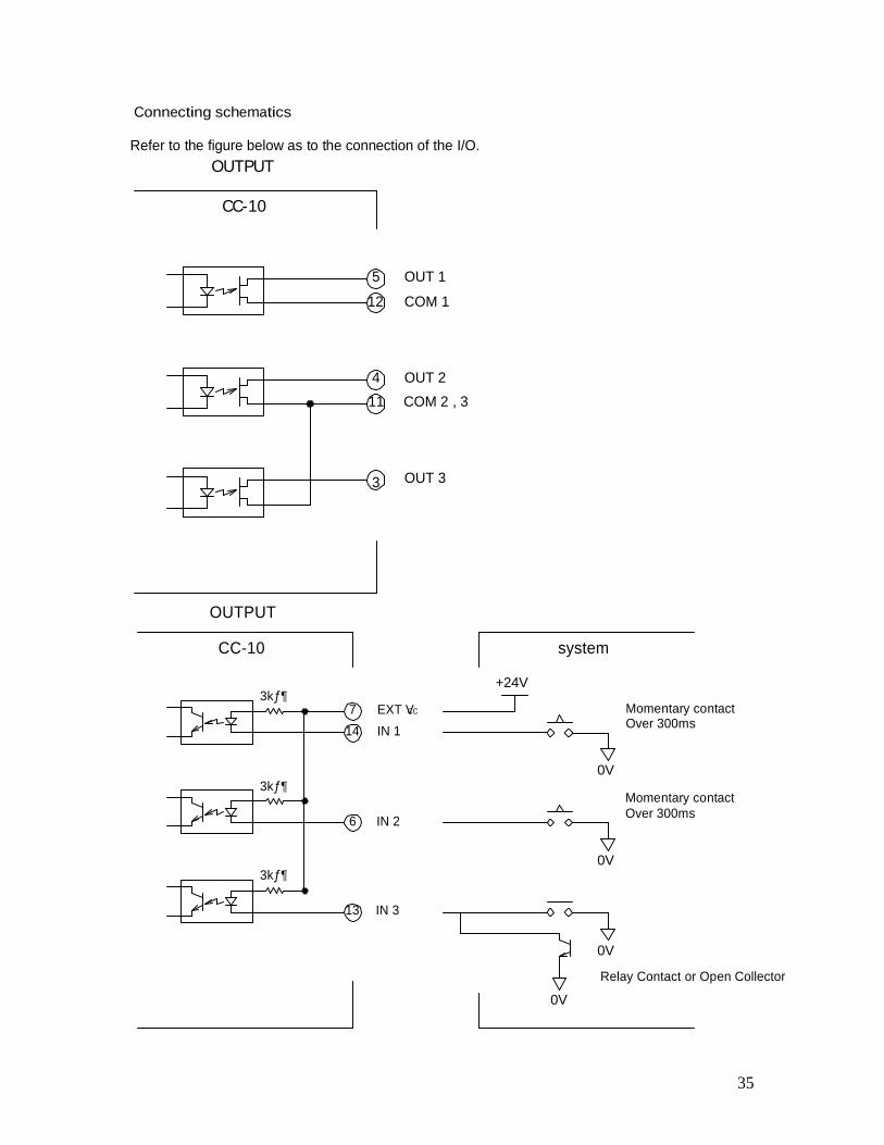
Connecting schematics
Refer to the figure below as to the connection of the I/O.OUTPUT
CC-10
5 OUT 1
12 COM 1
4 OUT 211 COM 2 , 3
3 OUT 3
OUTPUT
CC-10 system
3k ¶7 EXT VCC
14 IN 1
+24V
Momentary contactOver 300ms
3k 
6 IN 2
0V
Momentary contactOver 300ms
0V3k 
13 IN 3
0V
Relay Contact or Open Collector
0V
35
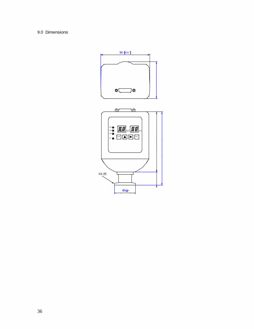
9.0 Dimensions
94 [m m ]
SP1
SP2
SP3
HVFUNC
x10 P a
ENT
N W 25
40
36
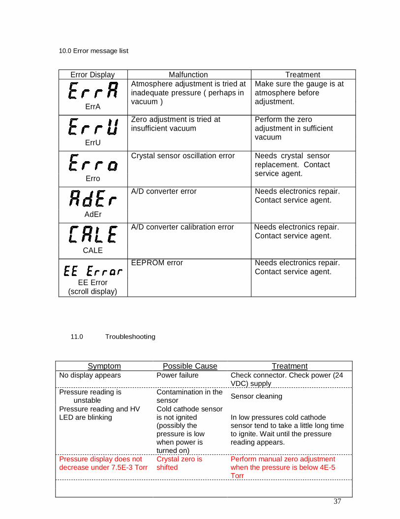
10.0 Error message list
Error Display Malfunction Treatment
ErrA
ErrU
Atmosphere adjustment is tried atinadequate pressure ( perhaps invacuum )
Zero adjustment is tried atinsufficient vacuum
Make sure the gauge is atatmosphere beforeadjustment.
Perform the zeroadjustment in sufficientvacuum
Erro
AdEr
CALE
EE Error(scroll display)
Crystal sensor oscillation error Needs crystal sensorreplacement. Contactservice agent.
A/D converter error Needs electronics repair.Contact service agent.
A/D converter calibration error Needs electronics repair.Contact service agent.
EEPROM error Needs electronics repair.Contact service agent.
11.0 Troubleshooting
Symptom Possible Cause TreatmentNo display appears Power failure Check connector. Check power (24
VDC) supplyPressure reading is
unstableContamination in thesensor Sensor cleaning
Pressure reading and HVLED are blinking
Cold cathode sensoris not ignited(possibly thepressure is lowwhen power isturned on)
In low pressures cold cathodesensor tend to take a little long timeto ignite. Wait until the pressurereading appears.
Pressure display does notdecrease under 7.5E-3 Torr
Crystal zero isshifted
Perform manual zero adjustmentwhen the pressure is below 4E-5Torr
37

For technical and applications assistance, please contact
Televac2400 Philmont Avenue
Huntingdon Valley, PA 19006Phone - (215) 947-2500Fax – (215) 947-7464
Email: [email protected]
38