Embed Size (px)
Citation preview
User's Manual
AJ65BTS-RPH
Thank you for buying the programmable controller MELSEC-A series.
© 2006 MITSUBISHI ELECTRIC CORPORATION
CC-Link SystemSpring Clamp Terminal
Block TypeRepeater Hub Module
Prior to use, please read both this manual and related manuals thoroughly and familiarize yourself with the product.
MODEL AJ65BTS-RPH-U
MODELCODE
13JP97
IB(NA)-0800346-E(1612)MEE
SAFETY PRECAUTIONS(Read these precautions before using.)
When using Mitsubishi equipment, thoroughly read this manual and the associated manuals introduced in this manual. Also pay careful attention to safety and handle the module properly.The precautions given in this manual are concerned with this product. Refer to the user's manual of the network system to use for a description of the network system safety precautions.In this manual, the safety precautions are classified into two levels: " WARNING" and " CAUTION".
Under some circumstances, failure to observe the precautions given under " CAUTION" may lead to serious consequences.Observe the precautions of both levels because they are important for personal and system safety.Make sure that the end users read this manual and then keep the manual in a safe place for future reference.
WARNINGIndicates that incorrect handling may cause
hazardous conditions, resulting in death or severe
injury.
Indicates that incorrect handling may cause
hazardous conditions, resulting in minor or moderate
injury or property damage.CAUTION
A-1
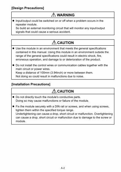
[Design Precautions]
[Installation Precautions]
Input/output could be switched on or off when a problem occurs in the repeater module.So build an external monitoring circuit that will monitor any input/output signals that could cause a serious accident.
Use the module in an environment that meets the general specifications contained in this manual. Using this module in an environment outside the range of the general specifications could result in electric shock, fire, erroneous operation, and damage to or deterioration of the product.
Do not install the control wires or communication cables together with the main circuit or power wires. Keep a distance of 100mm (3.94inch) or more between them. Not doing so could result in malfunctions due to noise.
Do not directly touch the module's conductive parts. Doing so may cause malfunctions or failure of the module.
Fix the module securely with a DIN rail or screws, and when using screws, tighten them within the specified torque range.Undertightening can cause a drop, short circuit or malfunction. Overtightening can cause a drop, short circuit or malfunction due to damage to the screw or module.
WARNING
CAUTION
CAUTION
A-2
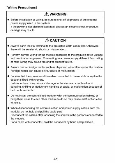
[Wiring Precautions]
Before installation or wiring, be sure to shut off all phases of the external power supply used in the system.If the power is not disconnected at all phases an electric shock or product damage may result.
Always earth the FG terminal to the protective earth conductor. Otherwise there will be an electric shock or misoperation.
Perform correct wiring for the module according to the product’s rated voltage and terminal arrangement. Connecting to a power supply different from rating or miss-wiring may cause fire and/or product failure.
Ensure that no foreign matter such as chips and wire-offcuts enter the module.Foreign matter can cause a fire, failure or malfunction.
Be sure that the communication cable connected to the module is kept in the duct or is fixed with cramps.Failure to do so may cause a damage to the module or cables due to dangling, shifting or inadvertent handling of cable, or malfunction because of bad cable contacts.
Do not install the control lines together with the communication cables, or bring them close to each other. Failure to do so may cause malfunctions due to noise.
When disconnecting the communication and power supply cables from the module, do not hold and pull the cable part.Disconnect the cables after loosening the screws in the portions connected to the module.For a cable with connector, hold the connector by hand and pull it out.
WARNING
CAUTION
A-3
[Starting and Maintenance Precautions]
[Disposal Precautions]
Do not disassemble or modify the modules.Doing so could cause failure, erroneous operation, injury, or fire.
Be sure to shut down all the phases of the externally supplied power used in the system before cleaning the module, retightening the module fixing screws, and attaching/removing the module.Not doing so can cause the module to fail or malfunction.
Do not install/remove the terminal block more than 50 times after the first use of the product. (IEC 61131-2 compliant)
Before handling the module, make sure to touch a grounded metal object to discharge the static electricity from the human body.Failure to do say cause a failure or malfunctions of the module.
When disposing of this product, treat it as industrial waste.
CAUTION
CAUTION
A-4
PRÉCAUTIONS DE SÉCURITÉ(Lire ces précautions avant toute utilisation.)
Pour l'utilisation des produits Mitsubishi, lire attentivement ce manuel ainsi que les autres documents ou manuels auxquels il renvoie. Observer aussi toutes les précautions de sécurité à propos de la manipulation du produit.Les précautions à observer figurant dans ce manuel concernent ce produit. Pour les consignes de sécurité concernant le réseau, prière de se reporter au manuel de l'utilisateur des systèmes du réseau.Dans ce manuel, les précautions de sécurité sont classées en deux niveaux, à savoir : " AVERTISSEMENT" et " ATTENTION"
Dans certaines circonstances, le non-respect d'une précaution de sécurité introduite sous le titre " ATTENTION"peut avoir des conséquences graves.Les précautions de ces deux niveaux doivent être observées dans leur intégralité car elles ont trait à la sécurité des personnes et aussi du système.Veiller à ce que les utilisateurs finaux lisent ce manuel qui doit être conservé soigneusement à portée de main pour s'y référer autant que de besoin.
AVERTISSEMENT Attire l'attention sur le fait qu'une négligence peut créer une situation de danger avec risque de mort ou de blessures graves.Attire l'attention sur le fait qu'une négligence peut créer une situation de danger avec risque de blessures légères ou de gravité moyennes ou risque de dégâts matériels.
ATTENTION
A-5
[Précautions lors de la conception]
[Précautions d'installation]
Les entrées/sorties peuvent se trouver activées ou désactivées par l'apparition d'un problème dans le module répéteur.On doit donc constituer un circuit de surveillance externe pour le suivi des signaux d'entrée/sortie qui pourraient être à l'origine d'accidents ou d'incidents graves.
Utiliser le module dans un environnement en conformité avec les spécifications générales que présente ce manuel. L'utilisation de ce module dans un environnement autre que celui prévu dans les spécifications générales peut être à l'origine d'un choc électrique, d'un départ de feu ou d'un dysfonctionnement, ou peut endommager ou détériorer le produit.
Ne pas installer les câble et fils de commande ou de communication avec les conducteurs des circuits principaux ou d'alimentation. Les installer en maintenant entre eux une distance minimum de 100mm (3,94 pouces). Il pourrait en résulter des dysfonctionnements par un bruit.
Éviter tout contact direct avec les parties conductrices du module. Cela pourrait entraîner des dysfonctionnements ou une panne du module.
Bien fixer le module avec un rail DIN ou des vis. Quand on utilise des vis, elles doivent être serrées au couple de serrage prescrit.Un serrage insuffisant peut être à l'origine d'une chute, d'un court-circuit ou d'un dysfonctionnement. Un serrage excessif risque d'endommager le module ou les vis dont la chute pourrait entraîner un court-circuit ou un dysfonctionnement.
AVERTISSEMENT
ATTENTION
ATTENTION
A-6
[Pécautions de câblage]
Avant installation ou câblage, toujours vérifier que les alimentations externes utilisées par le système ont été coupées sur toutes les phasesSi l'alimentation n'est pas déconnectée sur toutes les phases, il y a risque d'électrocution et d'endommagement du produit.
Toujours mettre à la masse la borne FG sur le conducteur de protection de terre. Autrement, il y aurait risque d'électrocution ou de dysfonctionnement.
Effectuer le câblage du module correctement, en respectant la tension nominale et l'affectation des bornes du produit. Le raccordement d'une alimentation de tension nominale différente ou une erreur de câblage peuvent être à l'origine d'un départ de feu et/ou d'une panne du produit.
Veiller à ce qu'aucun corps étrangers, copeaux, débris de fil ou autres, ne pénètre dans le module.Tout corps étranger peut être à l'origine d'un départ de feu, d'une panne ou d'un dysfonctionnement.
Vérifier que le câble de communication raccordé au module est bien maintenu immobile par un conduit de câble ou des colliers de fixation.Faute de quoi, le ballottement ou le déplacement des câbles par inadvertance pourrait endommager le module ou les câbles et être à l'origine de dysfonctionnements par mauvais contact.
Ne pas installer les lignes de commandes avec les câbles de communication et ne pas les placer à proximité les uns des autres. Faute de quoi, les bruits parasites produiront des dysfonctionnements.
Pour débrancher un câble de communication ou d'alimentation du module, ne pas tirer sur le câble lui-même.Débrancher les câbles après avoir desserré les vis de la prise de raccordement sur le module.Si le câble a un connecteur, saisir le connecteur au main et débrancher en tirant par le connecteur.
AVERTISSEMENT
ATTENTION
A-7
[Précautions de démarrage et de maintenance]
[Précaution de mise au rebut]
Ne pas démonter ni modifier les modules.Cela pourrait être à l'origine d'une panne ou d'un fonctionnement erratique et il y aurait risque de blessures ou de départ de feu.
Avant d'entreprendre de nettoyer le module, de resserrer les vis de fixation ou d'insérer/retirer le module, vérifier que l'alimentation externe du système a bien été coupée sur toutes les phases.Faute de quoi, il y a risque de panne ou de dysfonctionnement du module.
Après la mise en service du produit, le nombre maximum admissible d'opérations de pose/retrait de la plaque à bornes est de 50 (selon IEC 61131-2).
Avant de manipuler le module, toujours se débarrasser de la charge d'électricité statique dont le corps humain est porteur en touchant un objet métallique mis à la terre.Faute de quoi, il y a risque de panne ou de dysfonctionnements du module.
Lors de sa mise au rebut, ce produit doit être traité comme un déchet industriel.
ATTENTION
ATTENTION
A-8
CONDITIONS OF USE FOR THE PRODUCT
(1) Mitsubishi programmable controller ("the PRODUCT") shall be used in conditions;i) where any problem, fault or failure occurring in the PRODUCT, if any, shall not lead to any major or serious accident; and ii) where the backup and fail-safe function are systematically or automatically provided outside of the PRODUCT for the case of any problem, fault or failure occurring in the PRODUCT.
(2) The PRODUCT has been designed and manufactured for the purpose of being used in general industries.MITSUBISHI SHALL HAVE NO RESPONSIBILITY OR LIABILITY (INCLUDING, BUT NOT LIMITED TO ANY AND ALL RESPONSIBILITY OR LIABILITY BASED ON CONTRACT, WARRANTY, TORT, PRODUCT LIABILITY) FOR ANY INJURY OR DEATH TO PERSONS OR LOSS OR DAMAGE TO PROPERTY CAUSED BY the PRODUCT THAT ARE OPERATED OR USED IN APPLICATION NOT INTENDED OR EXCLUDED BY INSTRUCTIONS, PRECAUTIONS, OR WARNING CONTAINED IN MITSUBISHI'S USER, INSTRUCTION AND/OR SAFETY MANUALS, TECHNICAL BULLETINS AND GUIDELINES FOR the PRODUCT.("Prohibited Application")Prohibited Applications include, but not limited to, the use of the PRODUCT in;
• Nuclear Power Plants and any other power plants operated by Power companies, and/or any other cases in which the public could be affected if any problem or fault occurs in the PRODUCT.
• Railway companies or Public service purposes, and/or any other cases in which establishment of a special quality assurance system is required by the Purchaser or End User.
• Aircraft or Aerospace, Medical applications, Train equipment, transport equipment such as Elevator and Escalator, Incineration and Fuel devices, Vehicles, Manned transportation, Equipment for Recreation and Amusement, and Safety devices, handling of Nuclear or Hazardous Materials or Chemicals, Mining and Drilling, and/or other applications where there is a significant risk of injury to the public or property.
A-9

Notwithstanding the above, restrictions Mitsubishi may in its sole discretion, authorize use of the PRODUCT in one or more of the Prohibited Applications, provided that the usage of the PRODUCT is limited only for the specific applications agreed to by Mitsubishi and provided further that no special quality assurance or fail-safe, redundant or other safety features which exceed the general specifications of the PRODUCTs are required. For details, please contact the Mitsubishi representative in your region.
A-10

REVISIONS* The manual number is given on the bottom right of the cover.
© 2006 MITSUBISHI ELECTRIC CORPORATION
Print Date *Manual Number Revision
Oct., 2006 IB(NA)-0800346-A First edition
Dec., 2006 IB(NA)-0800346-B
SAFETY PRECAUTIONS, About the Manual, Section 2.2, 2.3, 3.1, 3.2, 4.2.1
Dec., 2011 IB(NA)-0800346-C
SAFETY PRECAUTIONS, ABOUT MANUALS, COMPLIANCE WITH THE EMC AND LOW VOLTAGE DIRECTIVES, Chapter 1, Section 2.3, 3.1, 3.4, 4.1, 4.2.1, Chapter 6
Jul., 2015 IB(NA)-0800346-D
ABOUT MANUALS, ABBREVIATED NAMES, GENERIC NAMES AND TERMS, Section 2.3, 3.2, 3.3, 4.2.1, 4.3
Dec., 2016 IB(NA)-0800346-E
SAFETY PRECAUTIONS (French)
Section 3.1, 4.3, Chapter 6
This manual confers no industrial property rights or any rights of any other kind, nor does it confer any patent licenses. Mitsubishi Electric Corporation cannot be held responsible for any problems involving industrial property rights which may occur as a result of using the contents noted in this manual.
Correction
Correction
Correction
Addition
Correction
A-11

A-12
CONTENTS
1. OVERVIEW ....................................................................................................1
1.1 Features ..................................................................................................1
2. SYSTEM CONFIGURATION .........................................................................3
2.1 Total configuration ...................................................................................3
2.2 Applicable system ....................................................................................4
2.3 Cautions on system configuration ...........................................................5
3. SPECIFICATION .........................................................................................12
3.1 General specifications ........................................................................... 12
3.2 Performance specifications ................................................................... 14
3.3 Specifications of connection cable ........................................................ 20
3.4 Maximum transmission distance ........................................................... 21
4. PROCEDURE UP TO START OF DATA LINK ............................................ 22
4.1 Procedure up to start of data link ........................................................... 22
4.2 Mounting and installation ....................................................................... 23
4.2.1 Cautions on handling ....................................................................23
4.2.2 Installation environment ................................................................ 26
4.3 Names and settings of parts .................................................................. 27
4.4 Connection of module through CC-Link dedicated cable ...................... 31
4.5 Check for state of connection (line test) ................................................ 32
5. TROUBLESHOOTING ................................................................................. 35
6. EXTERNAL DIMENSIONS .......................................................................... 39
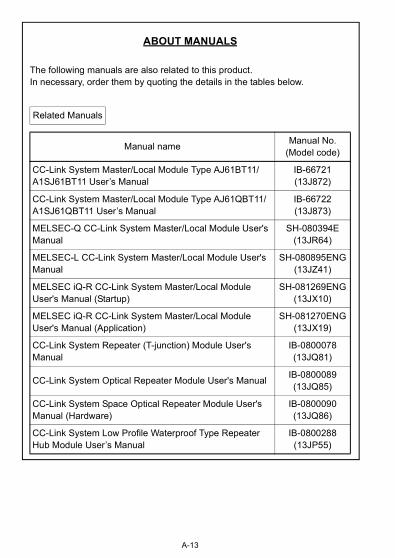
ABOUT MANUALS
The following manuals are also related to this product.In necessary, order them by quoting the details in the tables below.
Related Manuals
Manual nameManual No.
(Model code)
CC-Link System Master/Local Module Type AJ61BT11/A1SJ61BT11 User’s Manual
IB-66721(13J872)
CC-Link System Master/Local Module Type AJ61QBT11/A1SJ61QBT11 User’s Manual
IB-66722(13J873)
MELSEC-Q CC-Link System Master/Local Module User's Manual
SH-080394E(13JR64)
MELSEC-L CC-Link System Master/Local Module User's Manual
SH-080895ENG(13JZ41)
MELSEC iQ-R CC-Link System Master/Local Module User's Manual (Startup)
SH-081269ENG(13JX10)
MELSEC iQ-R CC-Link System Master/Local Module User's Manual (Application)
SH-081270ENG(13JX19)
CC-Link System Repeater (T-junction) Module User's Manual
IB-0800078(13JQ81)
CC-Link System Optical Repeater Module User's ManualIB-0800089(13JQ85)
CC-Link System Space Optical Repeater Module User's Manual (Hardware)
IB-0800090(13JQ86)
CC-Link System Low Profile Waterproof Type Repeater Hub Module User’s Manual
IB-0800288(13JP55)
A-13
COMPLIANCE WITH EMC AND LOW VOLTAGE DIRECTIVES
(1) Method of ensuring complianceTo ensure that Mitsubishi programmable controllers maintain EMC and Low Voltage Directives when incorporated into other machinery or equipment, certain measures may be necessary. Please refer to one of the following manuals.• User's manual for the CPU module or head module used• Safety Guidelines (this manual is included with the CPU module, base unit, or head module)The CE mark on the side of the programmable controller indicates compliance with EMC and Low Voltage Directives.
(2) Additional measuresTo ensure that this product maintains EMC and Low Voltage Directives, please refer to one of the manuals listed under (1).
A-14
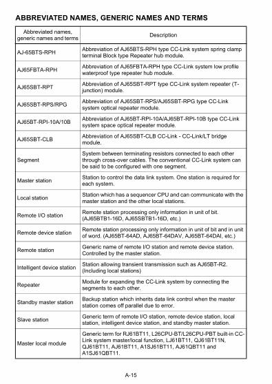
ABBREVIATED NAMES, GENERIC NAMES AND TERMS
Abbreviated names, generic names and terms
Description
AJ-65BTS-RPHAbbreviation of AJ65BTS-RPH type CC-Link system spring clamp terminal Block type Repeater hub module.
AJ65FBTA-RPHAbbreviation of AJ65FBTA-RPH type CC-Link system low profile waterproof type repeater hub module.
AJ65SBT-RPTAbbreviation of AJ65SBT-RPT type CC-Link system repeater (T-junction) module.
AJ65SBT-RPS/RPGAbbreviation of AJ65SBT-RPS/AJ65SBT-RPG type CC-Link system optical repeater module.
AJ65BT-RPI-10A/10BAbbreviation of AJ65BT-RPI-10A/AJ65BT-RPI-10B type CC-Link system space optical repeater module.
AJ65SBT-CLBAbbreviation of AJ65SBT-CLB CC-Link - CC-Link/LT bridge module.
SegmentSystem between terminating resistors connected to each other through cross-over cables. The conventional CC-Link system can be said to be configured with one segment.
Master stationStation to control the data link system. One station is required for each system.
Local stationStation which has a sequencer CPU and can communicate with the master station and the other local stations.
Remote I/O stationRemote station processing only information in unit of bit. (AJ65BTB1-16D, AJ65SBTB1-16D, etc.)
Remote device stationRemote station processing only information in unit of bit and in unit of word. (AJ65BT-64AD, AJ65BT-64DAV, AJ65BT-64DAI, etc.)
Remote stationGeneric name of remote I/O station and remote device station. Controlled by the master station.
Intelligent device stationStation allowing transient transmission such as AJ65BT-R2. (Including local stations)
RepeaterModule for expanding the CC-Link system by connecting the segments to each other.
Standby master stationBackup station which inherits data link control when the master station comes off parallel due to error.
Slave stationGeneric term of remote I/O station, remote device station, local station, intelligent device station, and standby master station.
Master local module
Generic term for RJ61BT11, L26CPU-BT/L26CPU-PBT built-in CC-Link system master/local function, LJ61BT11, QJ61BT11N, QJ61BT11, AJ61BT11, A1SJ61BT11, AJ61QBT11 and A1SJ61QBT11.
A-15
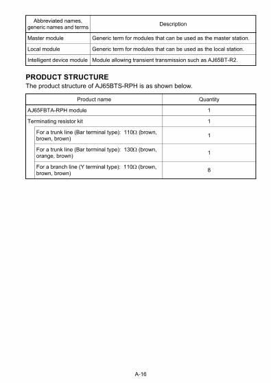
PRODUCT STRUCTUREThe product structure of AJ65BTS-RPH is as shown below.
Master module Generic term for modules that can be used as the master station.
Local module Generic term for modules that can be used as the local station.
Intelligent device module Module allowing transient transmission such as AJ65BT-R2.
Product name Quantity
AJ65FBTA-RPH module 1
Terminating resistor kit 1
For a trunk line (Bar terminal type): 110 (brown, brown, brown)
1
For a trunk line (Bar terminal type): 130(brown, orange, brown)
1
For a branch line (Y terminal type): 110(brown, brown, brown)
8
Abbreviated names, generic names and terms
Description
A-16
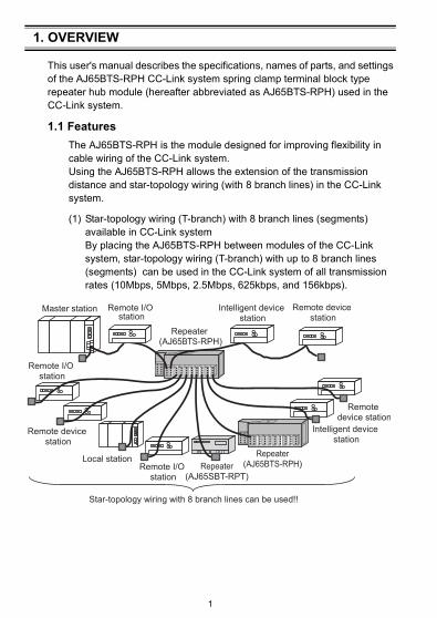
1. OVERVIEW
This user's manual describes the specifications, names of parts, and settings of the AJ65BTS-RPH CC-Link system spring clamp terminal block type repeater hub module (hereafter abbreviated as AJ65BTS-RPH) used in the CC-Link system.
1.1 Features
The AJ65BTS-RPH is the module designed for improving flexibility in cable wiring of the CC-Link system.Using the AJ65BTS-RPH allows the extension of the transmission distance and star-topology wiring (with 8 branch lines) in the CC-Link system.
(1) Star-topology wiring (T-branch) with 8 branch lines (segments) available in CC-Link systemBy placing the AJ65BTS-RPH between modules of the CC-Link system, star-topology wiring (T-branch) with up to 8 branch lines (segments) can be used in the CC-Link system of all transmission rates (10Mbps, 5Mbps, 2.5Mbps, 625kbps, and 156kbps).
IN OUT
Master station Remote I/O station
Repeater (AJ65BTS-RPH)
Intelligent device station
Remote device station
Remote I/O station
Remote device station
Local stationRemote I/O
stationRepeater
(AJ65SBT-RPT)
Repeater(AJ65BTS-RPH)
Intelligent device station
Remote device station
Star-topology wiring with 8 branch lines can be used!!
1
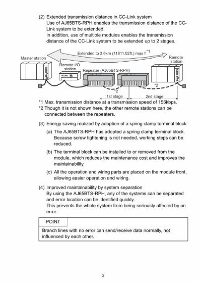
(2) Extended transmission distance in CC-Link systemUse of AJ65BTS-RPH enables the transmission distance of the CC-Link system to be extended.In addition, use of multiple modules enables the transmission distance of the CC-Link system to be extended up to 2 stages.
*1 Max. transmission distance at a transmission speed of 156kbps.*2 Though it is not shown here, the other remote stations can be
connected between the repeaters.
(3) Energy saving realized by adoption of a spring clamp terminal block
(a) The AJ65BTS-RPH has adopted a spring clamp terminal block. Because screw tightening is not needed, working steps can be reduced.
(b) The terminal block can be installed to or removed from the module, which reduces the maintenance cost and improves the maintainability.
(c) All the operation and wiring parts are placed on the module front, allowing easier operation and wiring.
(4) Improved maintainability by system separationBy using the AJ65BTS-RPH, any of the systems can be separated and error location can be identified quickly.This prevents the whole system from being seriously affected by an error.
POINT
Branch lines with no error can send/receive data normally, not influenced by each other.
Remote station
Remote I/O station Repeater (AJ65BTS-RPH)
Extended to 3.6km (11811.02ft.) max !!*1
*2
1st stage 2nd stage
*2
Master station
2

2. SYSTEM CONFIGURATION
2.1 Total configuration
The total configuration employed when the AJ65BTS-RPH is used is as shown below.
*1 The transmission speed of each segment must be matched with that of the master station.
*2 2 stages of segments max. are allowed to be used.*3 The 130 terminating resistor is not usable for a segment connected
on the branch line side of the AJ65BTS-RPH.Use the 110 terminating resistor that is included with the AJ65BTS-RPH.
Master station*1
[Segment]
RemoteI/O station
RemoteI/O station
Local station
RemoteI/O station
Remotedevice station
Remotedevice station
Remotedevice station
Intelligentdevice station
Intelligentdevice station
Terminating resistor(indispensable)
Terminating resistor(indispensable)
Repeater (AJ65BTS-RPH)
Repeater (AJ65BTS-RPH) Repeater (AJ65BTS-RPH)
[Segment (1st stage)]
[Segment (2nd stage)*2]
Terminating resistor,110Ω (indispensable)*3
Terminating resistor, 110Ω (built-in)*3
Terminating resistor,110Ω (indispensable)*3
Terminating resistor,110Ω (indispensable)*3
Terminating resistor,110Ω (indispensable)*3
Terminating resistor,110Ω (indispensable)*3
3
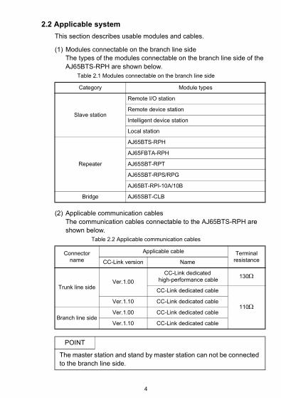
2.2 Applicable system
This section describes usable modules and cables.
(1) Modules connectable on the branch line sideThe types of the modules connectable on the branch line side of the AJ65BTS-RPH are shown below.
Table 2.1 Modules connectable on the branch line side
(2) Applicable communication cablesThe communication cables connectable to the AJ65BTS-RPH are shown below.
Table 2.2 Applicable communication cables
Category Module types
Slave station
Remote I/O station
Remote device station
Intelligent device station
Local station
Repeater
AJ65BTS-RPH
AJ65FBTA-RPH
AJ65SBT-RPT
AJ65SBT-RPS/RPG
AJ65BT-RPI-10A/10B
Bridge AJ65SBT-CLB
Connector name
Applicable cable Terminal resistanceCC-Link version Name
Trunk line sideVer.1.00
CC-Link dedicated high-performance cable
130
CC-Link dedicated cable
110Ver.1.10 CC-Link dedicated cable
Branch line sideVer.1.00 CC-Link dedicated cable
Ver.1.10 CC-Link dedicated cable
POINT
The master station and stand by master station can not be connected to the branch line side.
4
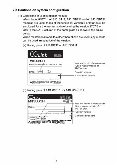
2.3 Cautions on system configuration
(1) Conditions of usable master moduleWhen the AJ61BT11, A1SJ61BT11, AJ61QBT11 and A1SJ61QBT11 modules are used, those of the functional version B or later must be employed. Use the master module bearing the version 9707 B or later in the DATE column of the name plate as shown in the figure below. When master/local modules other than above are used, any module can be used irrespective of the version.
(a) Rating plate of AJ61BT11 or AJ61QBT11
(b) Rating plate of A1SJ61BT11 or A1SJ61QBT11
PROGRAMMABLE CONTROLLER
DATE
MADE IN JAPAN BD992C077H01
yymm B
Year and month of manufacture(Use a master module of 9707 or later.)
Function version
Conformed standard
MODEL
POWER
DATE
MADE IN JAPAN BD992C077H01
Byymm
Year and month of manufacture(Use a master module of 9707 or later.)
Function version
Conformed standard
5
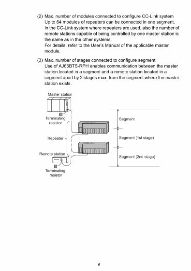
(2) Max. number of modules connected to configure CC-Link systemUp to 64 modules of repeaters can be connected in one segment.In the CC-Link system where repeaters are used, also the number of remote stations capable of being controlled by one master station is the same as in the other systems.For details, refer to the User’s Manual of the applicable master module.
(3) Max. number of stages connected to configure segmentUse of AJ65BTS-RPH enables communication between the master station located in a segment and a remote station located in a segment apart by 2 stages max. from the segment where the master station exists.
Master station
Terminatingresistor
Terminating resistor
Repeater
Segment
Segment (1st stage)
Segment (2nd stage)Remote station
6
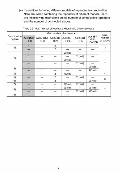
(4) Instructions for using different models of repeaters in combinationNote that when combining the repeaters of different models, there are the following restrictions on the number of connectable repeaters and the number of connected stages.
Table 2.3 Max. number of repeaters when using different models
Combination pattern
Max. number of repeatersMax.
number of stages
AJ65BTS-RPH
AJ65FBTA-RPH
AJ65SBT-RPT
AJ65SBT-RPS
AJ65SBT-RPG
AJ65BT-RPI
-10A/10B
1)1 — 2 — — —
3— 1 2 — — —
2)
1 — — 2(1set) - —
2
1 — — — 2(1set) —
— 1 — 2(1set) — —
— 1 — — 2(1set) —
3)1 — — — — 2(1set)
— 1 — — — 2(1set)
4) — — 2 4(2set) — — 4
5) — — 2 — 2(1set) —3
6) — — 2 — — 2(1set)
7) — — — 2(1set) 2(1set) —
28)— — — 2(1set) — 2(1set)
— — — — 2(1set) 2(1set)
9) 1 1 — — — —
7
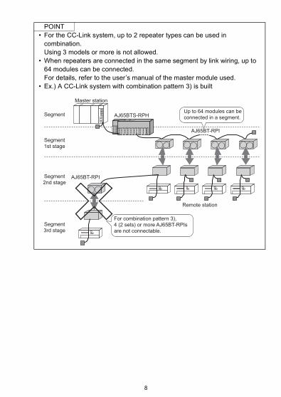
POINT• For the CC-Link system, up to 2 repeater types can be used in
combination.Using 3 models or more is not allowed.
• When repeaters are connected in the same segment by link wiring, up to 64 modules can be connected.For details, refer to the user’s manual of the master module used.
• Ex.) A CC-Link system with combination pattern 3) is built
Segment
Master station
AJ65BTS-RPH
AJ65BT-RPI
Remote station
AJ65BT-RPI
For combination pattern 3), 4 (2 sets) or more AJ65BT-RPIs are not connectable.
Segment1st stage
Segment2nd stage
Segment3rd stage
Up to 64 modules can be connected in a segment.
8
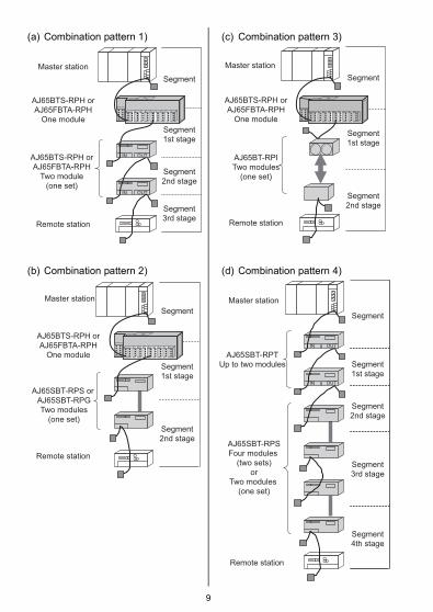
(a) Combination pattern 1) (c) Combination pattern 3)
(b) Combination pattern 2) (d) Combination pattern 4)
IN OUT
IN OUT
Master station
Segment
Segment
1st stage
Segment
2nd stage
Segment
3rd stageRemote station
AJ65BTS-RPH or
AJ65FBTA-RPH
One module
AJ65BTS-RPH or
AJ65FBTA-RPH
Two module
(one set)
Master stationSegment
Segment1st stage
Segment2nd stage
Remote station
AJ65BTS-RPH orAJ65FBTA-RPH
One module
AJ65BT-RPITwo modules
(one set)
Master station
Segment
Segment
1st stage
Segment
2nd stage
Remote station
AJ65BTS-RPH or
AJ65FBTA-RPH
One module
AJ65SBT-RPS or
AJ65SBT-RPG
Two modules
(one set)
IN OUT
IN OUT
Master station
Segment
Segment
1st stage
Segment
2nd stage
Segment
3rd stage
Segment
4th stage
Remote station
AJ65SBT-RPT
Up to two modules
AJ65SBT-RPS
Four modules
(two sets)
or
Two modules
(one set)
9
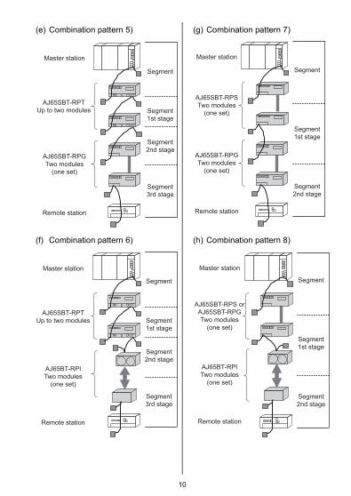
(e) Combination pattern 5) (g) Combination pattern 7)
(f) Combination pattern 6) (h) Combination pattern 8)
IN OUT
IN OUT
Master station
Segment
Segment
1st stage
Segment
2nd stage
Segment
3rd stage
Remote station
AJ65SBT-RPT
Up to two modules
AJ65SBT-RPG
Two modules
(one set)
Master station
Segment
Segment
1st stage
Segment
2nd stage
Remote station
AJ65SBT-RPS
Two modules
(one set)
AJ65SBT-RPG
Two modules
(one set)
IN OUT
IN OUT
Master station
Segment
Segment
1st stage
Segment
2nd stage
Segment
3rd stage
Remote station
AJ65SBT-RPT
Up to two modules
AJ65BT-RPI
Two modules
(one set)
Master station
Segment
Segment
1st stage
Segment
2nd stage
Remote station
AJ65SBT-RPS or
AJ65SBT-RPG
Two modules
(one set)
AJ65BT-RPI
Two modules
(one set)
10

(i) Combination pattern 9)
Master stationSegment
Segment1st stage
Segment2nd stage
Remote station
AJ65BTS-RPHOne module
AJ65FBTA-RPHOne module
11
3. SPECIFICATION
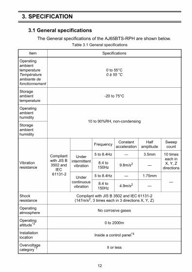
3.1 General specifications
The General specifications of the AJ65BTS-RPH are shown below.Table 3.1 General specifications
Item Specifications
Operating ambient temperatureTempérature ambiante de fonctionnement
0 to 55°C0 à 55 °C
Storage ambient temperature
-20 to 75°C
Operating ambient humidity
10 to 90%RH, non-condensingStorage ambient humidity
Vibration resistance
Compliant with JIS B 3502 and
IEC 61131-2
FrequencyConstant
accelerationHalf
amplitudeSweep count
Under intermittent
vibration
5 to 8.4Hz — 3.5mm 10 times each in X, Y, Z
directions8.4 to 150Hz
9.8m/s2 —
Under continuous vibration
5 to 8.4Hz — 1.75mm
—8.4 to 150Hz
4.9m/s2 —
Shock resistance
Compliant with JIS B 3502 and IEC 61131-2(147m/s2, 3 times each in 3 directions X, Y, Z)
Operating atmosphere
No corrosive gases
Operating altitude*3 0 to 2000m
Installation location
Inside a control panel*4
Overvoltage category*1 II or less
12
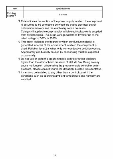
*1 This indicates the section of the power supply to which the equipment is assumed to be connected between the public electrical power distribution network and the machinery within premises.Category II applies to equipment for which electrical power is supplied from fixed facilities. The surge voltage withstand level for up to the rated voltage of 300V is 2500V.
*2 This index indicates the degree to which conductive material is generated in terms of the environment in which the equipment is used. Pollution level 2 is when only non-conductive pollution occurs.A temporary conductivity caused by condensing must be expected occasionally.
*3 Do not use or store the programmable controller under pressure higher than the atmospheric pressure of altitude 0m. Doing so may cause malfunction. When using the programmable controller under pressure, please consult your local Mitsubishi Electric representative.
*4 It can also be installed to any other than a control panel if the conditions such as operating ambient temperature and humidity are satisfied.
Pollution degree*2 2 or less
Item Specifications
13

3.2 Performance specifications
The performance specifications of the AJ65BTS-RPH module are shown below.
Table 3.2 Performance specifications (1/2)
Item Specifications
Station number - (none)
CC-Link station type
- (none)
Number of occupied stations
0 (none)
Transmission rate Can select from 156kbps / 625kbps / 2.5Mbps / 5Mbps / 10Mbps
No. of connectable slave stations
The total number of modules connected to a trunk line and branch line shall conform to the maximum number of connectable modules of the master module used.For details, refer to the user’s manual of the master modules used.
Max. No. of modules connected to the trunk line
64 (Refer to Section 2.3(2))
Connection position
Trunk line side
No restriction (compliant with the CC-Link specifications)
Branch line side
Connect to the end of the branch line (segment end)
Max. number of stages connected to configure segment
AJ65BTS-RPH only (Refer to Section 2.3(3)) 2nd stage
Combination of AJ65BTS-RPH and AJ65SBT-RPT (Refer to Section 2.3 (4))
3rd stage
Combination of AJ65BTS-RPH and one of AJ65FBTA-RPH, AJ65SBT-RPS/RPG, or AJ65BT-RPI (Refer to Section 2.3 (4))
2nd stage
Max. transmission distance of each segment
Varies according to transmission rate (Refer to Section 3.4.).
Terminating resistor
Trunk line side
110, or 130 can be selected.
Branch line side
110 (built-in)
External interfaceSpring clamp terminal block
Plaque à bornes avec bride à ressort
14

Applicable cable sizeTaille de câble à utiliser
24 to 12 AWG, 0.5 to 1.78mm Single wire,0.2 to 2.5mm2 stranded cable
24 à 12 AWG, 0,5 à 1,78mm Monobrin,0,2 à 2,5mm2 Torsadé Câble
Applicable solderless terminalBorne sans soudure à utiliser
Refer to table 3.3Voir Table 3.3
Item Specifications
15
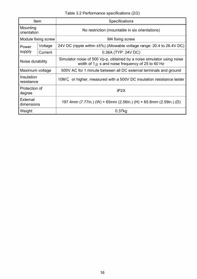
Table 3.2 Performance specifications (2/2)
Item Specifications
Mounting orientation
No restriction (mountable in six orientations)
Module fixing screw M4 fixing screw
Power supply
Voltage 24V DC (ripple within ±5%) (Allowable voltage range: 20.4 to 26.4V DC)
Current 0.36A (TYP. 24V DC)
Noise durabilitySimulator noise of 500 Vp-p, obtained by a noise simulator using noise
width of 1 s and noise frequency of 25 to 60 Hz
Maximum voltage 500V AC for 1 minute between all DC external terminals and ground
Insulation resistance
10M or higher, measured with a 500V DC insulation resistance tester
Protection of degree
IP2X
External dimensions
197.4mm (7.77in.) (W) × 65mm (2.56in.) (H) × 65.8mm (2.59in.) (D)
Weight 0.37kg
16
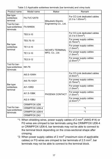
Table 3.3 Applicable solderless terminals (bar terminals) and crimp tools
*1: When shielding wires, power supply cables of 2 mm2 (AWG #14) or FG wires are crimped to bar terminals using the CRIMPFOX UD6-4 or CRIMPFOX UD6-6, bar terminals may not be able to connect to the terminal block depending on the cross-sectional shape after crimping.
*2: When power supply cables of 2 mm2 (maximum size of applicable cables) or FG wires are crimped to bar terminals of 2.5 mm2, bar terminals may not be able to connect to the terminal block.
Product name Model name Maker Remark
Bar-type solderless terminal
FA-TVC125T9Mitsubishi Electric Engineering Co., Ltd.
For CC-Link dedicated cables(0.3 to 1.65mm2)
Tool for bar-type solderless terminals
FA-NH65A
Bar-type solderless terminal
TE0.5-10
NICHIFU TERMINAL MFG. Co., Ltd.
For CC-Link dedicated cables(0.3 to 0.5mm2)
TE0.75-10For power supply cables(0.75mm2)
TE1.0-10For power supply cables(1.0mm2)
TE1.5-10For power supply cables(1.5mm2)
TE2.5-12For power supply cables(2.5mm2)*2
Tool for bar-type solderless terminals
NH-79
Bar-type solderless terminal
AI0.5-10WH
PHOENIX CONTACT
For CC-Link dedicated cables(0.5mm2)
AI0.75-10GYFor power supply cables(0.75mm2)
AI1-10RDFor power supply cables(1.0mm2)
AI1.5-10BKFor power supply cables(1.5mm2)
AI2.5-10BUFor power supply cables(2.5mm2)*2
Tool for bar-type solderless terminals
CRIMPFOX UD6
CRIMPFOX UD6-4 *1
CRIMPFOX UD6-6 *1
CRIMPFOX ZA3
17
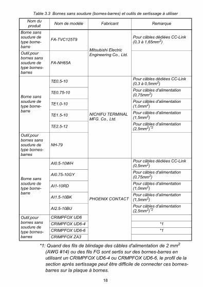
Table 3.3 Bornes sans soudure (bornes-barres) et outils de sertissage à utiliser
*1: Quand des fils de blindage des câbles d'alimentation de 2 mm2 (AWG #14) ou des fils FG sont sertis sur des bornes-barres en utilisant un CRIMPFOX UD6-4 ou CRMPFOX UD6-6, le profil de la section après sertissage peut être difficile de connecter ces bornes-barres sur la plaque à bornes.
Nom du produit
Nom de modèle Fabricant Remarque
Borne sans soudure de type borne-barre
FA-TVC125T9
Mitsubishi Electric Engineering Co., Ltd.
Pour câbles dédiées CC-Link(0,3 à 1,65mm2)
Outil,pour bornes sans soudure de type bornes-barres
FA-NH65A
Borne sans soudure de type borne-barre
TE0.5-10
NICHIFU TERMINAL MFG. Co., Ltd.
Pour câbles dédiées CC-Link(0,3 à 0,5mm2)
TE0.75-10Pour câbles d'alimentation(0,75mm2)
TE1.0-10Pour câbles d'alimentation(1,0mm2)
TE1.5-10Pour câbles d'alimentation(1,5mm2)
TE2.5-12Pour câbles d'alimentation(2,5mm2)*2
Outil,pour bornes sans soudure de type bornes-barres
NH-79
Borne sans soudure de type borne-barre
AI0.5-10WH
PHOENIX CONTACT
Pour câbles dédiées CC-Link(0,5mm2)
AI0.75-10GYPour câbles d'alimentation(0,75mm2)
AI1-10RDPour câbles d'alimentation(1,0mm2)
AI1.5-10BKPour câbles d'alimentation(1,5mm2)
AI2.5-10BUPour câbles d'alimentation(2,5mm2)*2
Outil,pour bornes sans soudure de type bornes-barres
CRIMPFOX UD6
CRIMPFOX UD6-4 *1
CRIMPFOX UD6-6 *1
CRIMPFOX ZA3
18

*2: Quand des câbles d'alimentation de 2 mm2 (maximum admissible pour la section du câble) ou des fils FG sont sertis sur des bornes-barres de 2,5 mm2, il peut être difficile de connecter ces bornes-barres sur la plaque à bornes.
19
3.3 Specifications of connection cable
Use the CC-Link dedicated cable for the CC-Link system. If a cable other than the CC-Link dedicated cable is used, the performance of the CC-Link system cannot be guaranteed.For the CC-Link cable specifications and any other inquiries, refer to the following:CC-Link Partner Association website: www.cc-link.org
For details, refer to the CC-Link cable wiring manual issued by the CC-Link Partner Association.
REMARK
20
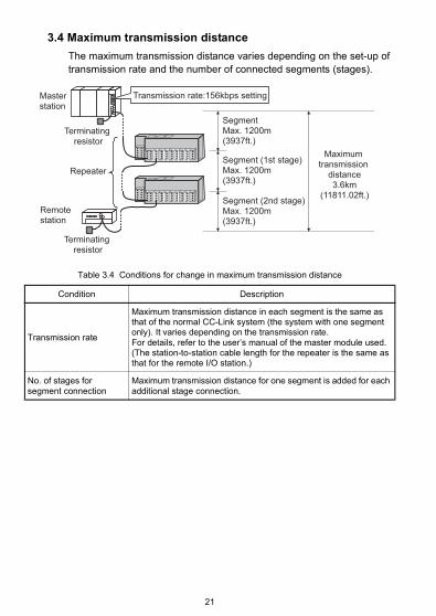
3.4 Maximum transmission distance
The maximum transmission distance varies depending on the set-up of transmission rate and the number of connected segments (stages).
Table 3.4 Conditions for change in maximum transmission distance
Condition Description
Transmission rate
Maximum transmission distance in each segment is the same as that of the normal CC-Link system (the system with one segment only). It varies depending on the transmission rate. For details, refer to the user’s manual of the master module used. (The station-to-station cable length for the repeater is the same as that for the remote I/O station.)
No. of stages for segment connection
Maximum transmission distance for one segment is added for each additional stage connection.
Master station
Remote station
Repeater
Transmission rate:156kbps setting
Terminating resistor
SegmentMax. 1200m (3937ft.)
Segment (1st stage)Max. 1200m (3937ft.)
Maximum transmission
distance3.6km
(11811.02ft.)Segment (2nd stage)Max. 1200m (3937ft.)
Terminating resistor
21
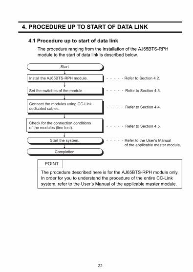
4. PROCEDURE UP TO START OF DATA LINK
4.1 Procedure up to start of data link
The procedure ranging from the installation of the AJ65BTS-RPH module to the start of data link is described below.
POINT
The procedure described here is for the AJ65BTS-RPH module only. In order for you to understand the procedure of the entire CC-Link system, refer to the User’s Manual of the applicable master module.
Refer to Section 4.2.
Start
Start the system.
Completion
Install the AJ65BTS-RPH module.
Refer to Section 4.3.Set the switches of the module.
Refer to the User’s Manual of the applicable master module.
Refer to Section 4.4.Connect the modules using CC-Link dedicated cables.
Refer to Section 4.5.Check for the connection conditions of the modules (line test).
22
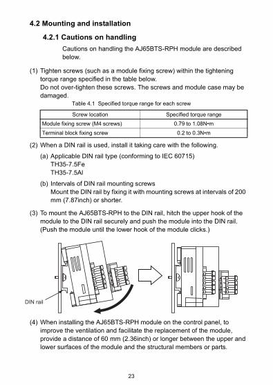
4.2 Mounting and installation
4.2.1 Cautions on handling
Cautions on handling the AJ65BTS-RPH module are described below.
(1) Tighten screws (such as a module fixing screw) within the tightening torque range specified in the table below.Do not over-tighten these screws. The screws and module case may be damaged.
Table 4.1 Specified torque range for each screw
(2) When a DIN rail is used, install it taking care with the following.
(a) Applicable DIN rail type (conforming to IEC 60715)TH35-7.5FeTH35-7.5Al
(b) Intervals of DIN rail mounting screwsMount the DIN rail by fixing it with mounting screws at intervals of 200 mm (7.87inch) or shorter.
(3) To mount the AJ65BTS-RPH to the DIN rail, hitch the upper hook of the module to the DIN rail securely and push the module into the DIN rail. (Push the module until the lower hook of the module clicks.)
(4) When installing the AJ65BTS-RPH module on the control panel, to improve the ventilation and facilitate the replacement of the module, provide a distance of 60 mm (2.36inch) or longer between the upper and lower surfaces of the module and the structural members or parts.
Screw location Specified torque range
Module fixing screw (M4 screws) 0.79 to 1.08N•m
Terminal block fixing screw 0.2 to 0.3N•m
DIN rail
23

(5) Install the AJ65BTS-RPH module on a flat smooth surface.If there are irregularities on the installation surface, undue force may be applied to the printed circuit boards, and the boards may be damaged.
(6) Depending on the grounding condition of the system, a high-frequency noise may occur between the systems. When these systems are connected through CC-Link communication cables, a communication error may occur by the mixing of noise into the repeaters.If the high-frequency noise occurs between the systems connected through the cables of 10 m (32.79ft.) or shorter, take either of the measures specified below.
Method1:Connect the systems through cables of 2 mm2 or larger (across FG terminals of the remote station in each system, or across grounds of the control panel to which the remote station is grounded).
Method2:Use CC-Link cables of 10 m (32.79ft.) or longer between the systems.
Repeater Hub
(AJ65BTS-RPH) Source of high-frequencynoise (Serov, inverter)
(To the ground)
Remote station
Remote station
Remote station
System 2 Control panel which may produce noiseSystem 1
Source of high-frequencynoise (Serov, inverter)
System 3 Control panel which may produce noise
Method 1: Use the stronger ground cable (2mm2 or larger).
Method 2: Use the cables of 10m (32.79ft.) or longer.
24

(7) Stripping the cable end
(a) The cable strip length must be approx. 10mm. If the cable is stripped too much, conductors may stick out of the terminal block and may cause an electric shock or short circuit with an adjacent terminal block.If the stripped length is too short, sufficient contact may not be ensured.
(b) For use of bar terminals, pay attention to the following:1) Select a bar terminal suitable for the cable size.2) Use an appropriate crimp tool to crimp the bar terminal.3) Insert the cable so that cable cores will stick out 0 to 0.5mm from
the sleeve edge.
4) Check the appearance of the bar terminal after crimping. If it is notcrimped properly or is damaged on the side, do not use the terminal. (See the following illustrations.)
Cable
Approx.10mm
0 to 0.5mm
Cable
Shell
Sleeve
Damaged Brokenedge
Not inserted intothe shell completely
Straywire
25
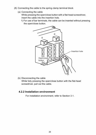
(8) Connecting the cable to the spring clamp terminal block
(a) Connecting the cableWhile pressing the open/close button with a flat-head screwdriver, insert the cable into the insertion hole.1) For use of bar terminals, the cable can be inserted without pressing
the open/close button.
(b) Disconnecting the cableWhile fully pressing the open/close button with the flat-head screwdriver, pull out the cable.
4.2.2 Installation environment
For installation environment, refer to Section 3.1.
Insertion hole
Open/closebuttonOpen/closebuttonOpen/closebutton
26
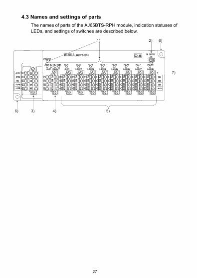
4.3 Names and settings of parts
The names of parts of the AJ65BTS-RPH module, indication statuses of LEDs, and settings of switches are described below.
6)
6)
7)
2)
3) 4) 5)
1)
27

Table 4.2 Names and settings of parts (1/3)
No. Name Application
1)Operation status display LED
Check for the module condition by observing the state of lighting of the LED.
LED Name Application
POWERON : Power supply onOFF : Power supply off
RUNON : Module is operating normallyOFF : Module is not operating normally
SDLINK IN/OUT
ON : Data are being sent to the LINK IN or LINK OUT of the trunk line
OFF : Data are not being sent to the LINK IN or LINK OUT of the trunk line
RDLINK IN/OUT
ON : Data are being received from the LINK IN or LINK OUT of the trunk line
OFF : Data are not being received from the LINK IN or LINK OUT of the trunk line
ERR.
ON : Transmission rate setting out-of-range error or communication error occurred
Flickering : Terminating resistor is missing. The module and CC-Link cables are affected by noise. Or the transmission rate was changed after power up.
OFF : Module is operating normally
RD LINK 1 to 8
ON : Data are being received from the LINK1 to 8 of the branch line.
OFF : Data are not being received from the LINK1 to 8 of the branch line.
28
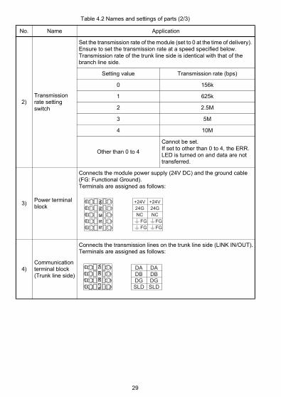
Table 4.2 Names and settings of parts (2/3)
No. Name Application
2)Transmission rate setting switch
Set the transmission rate of the module (set to 0 at the time of delivery). Ensure to set the transmission rate at a speed specified below.Transmission rate of the trunk line side is identical with that of the branch line side.
Setting value Transmission rate (bps)
0 156k
1 625k
2 2.5M
3 5M
4 10M
Other than 0 to 4
Cannot be set.If set to other than 0 to 4, the ERR. LED is turned on and data are not transferred.
3)Power terminal block
Connects the module power supply (24V DC) and the ground cable (FG: Functional Ground).Terminals are assigned as follows:
4)Communication terminal block (Trunk line side)
Connects the transmission lines on the trunk line side (LINK IN/OUT).Terminals are assigned as follows:
+24V24GNC
FG FG
+24V24GNC
FG FG
DADBDGSLD
DADBDGSLD
29
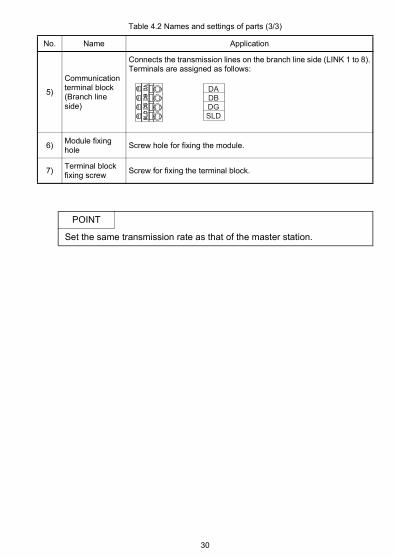
Table 4.2 Names and settings of parts (3/3)
No. Name Application
5)
Communication terminal block (Branch line side)
Connects the transmission lines on the branch line side (LINK 1 to 8).Terminals are assigned as follows:
6)Module fixing hole
Screw hole for fixing the module.
7)Terminal block fixing screw
Screw for fixing the terminal block.
POINT
Set the same transmission rate as that of the master station.
DADBDGSLD
30

4.4 Connection of module through CC-Link dedicated cable
The method of connecting the AJ65BTS-RPH module to the CC-Link system through the CC-Link dedicated cable is shown below.
For (1) to (5) shown in the above, read the following cautions on connections.
(1) For the segment connected to the trunk line side of the AJ65BTS-RPH, connect a terminating resistor to the module connected at the end.Select a type for terminating resistor in accordance with the type of the connected communication cable.For details, refer to the manual of the module connected.
(2) Do not connect any terminating resistor to the AJ65BTS-RPH when the trunk line side is connected to a station that is not located at the end of the segment.In addition, connect the shielding wire of the CC-Link dedicated cable to “SLD” of each module, and ground both ends via “FG” The interval between SLD and FG is connected in the module in advance.
(3) Connect the included terminating resistor to the AJ65BTS-RPH when the trunk line side is connected to a station that is located at the end of the segment.Select a type for terminating resistor in accordance with the type of the connected communication cable.For details, refer to Section 2.2.In addition, connect the shielding wire of the CC-Link dedicated cable to “SLD” of each module, and ground both ends via “FG” The interval between SLD and FG is connected in the module in advance.
Master station Remote I/Ostation
Intelligent device station
Repeater(AJ65BTS-RPH)
Repeater(AJ65BTS-RPH)
Remote I/Ostation
Remote I/Ostation
(3)(2)
(5)
(1)
(4)
31
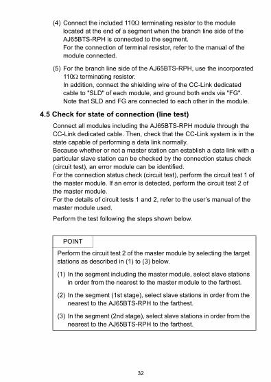
(4) Connect the included 110 terminating resistor to the module located at the end of a segment when the branch line side of the AJ65BTS-RPH is connected to the segment.For the connection of terminal resistor, refer to the manual of the module connected.
(5) For the branch line side of the AJ65BTS-RPH, use the incorporated 110 terminating resistor.In addition, connect the shielding wire of the CC-Link dedicated cable to "SLD" of each module, and ground both ends via "FG".Note that SLD and FG are connected to each other in the module.
4.5 Check for state of connection (line test)
Connect all modules including the AJ65BTS-RPH module through the CC-Link dedicated cable. Then, check that the CC-Link system is in the state capable of performing a data link normally.Because whether or not a master station can establish a data link with a particular slave station can be checked by the connection status check (circuit test), an error module can be identified.For the connection status check (circuit test), perform the circuit test 1 of the master module. If an error is detected, perform the circuit test 2 of the master module.For the details of circuit tests 1 and 2, refer to the user’s manual of the master module used.
Perform the test following the steps shown below.
POINT
Perform the circuit test 2 of the master module by selecting the target stations as described in (1) to (3) below.
(1) In the segment including the master module, select slave stations in order from the nearest to the master module to the farthest.
(2) In the segment (1st stage), select slave stations in order from the nearest to the AJ65BTS-RPH to the farthest.
(3) In the segment (2nd stage), select slave stations in order from the nearest to the AJ65BTS-RPH to the farthest.
32

YES
NO
NO
YES
1)
Start
Does POWER LEDlight up?
Does RUN LEDlight up?
Confirm that input power supply voltage is correct, and turn on the external power supply.
Refer to Chapter 5 (1) to perform troubleshooting.
Refer to Chapter 5 (2) to perform troubleshooting.
NO
YES
YES
NO
Perform the circuit test 1 of the master module.
Completion
Completion
Perform the circuit test 2 of the master module.
Any error detected in the circuit test 1?
Any error detected in the circuit test 2?
33
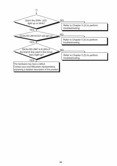
YES
NO
NO
YES
YES
NO
1)
The hardware may have a defect. Contact your local Mitsubishi representative, explaining a detailed description of the problem.
Didn't the ERR. LED light up or blink?
Did the RD LINK IN/OUT LED light up?
Did the RD LINK1 to 8 LEDs of the branch line used in the circuit
test 2 light up?
Refer to Chapter 5 (3) to perform troubleshooting.
Refer to Chapter 5 (4) to perform troubleshooting.
Refer to Chapter 5 (5) to perform troubleshooting.
34
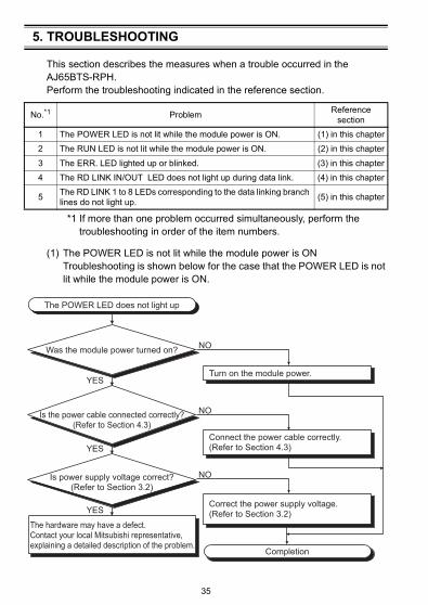
5. TROUBLESHOOTING
This section describes the measures when a trouble occurred in the AJ65BTS-RPH.Perform the troubleshooting indicated in the reference section.
*1 If more than one problem occurred simultaneously, perform the troubleshooting in order of the item numbers.
(1) The POWER LED is not lit while the module power is ONTroubleshooting is shown below for the case that the POWER LED is not lit while the module power is ON.
No.*1 ProblemReference
section
1 The POWER LED is not lit while the module power is ON. (1) in this chapter
2 The RUN LED is not lit while the module power is ON. (2) in this chapter
3 The ERR. LED lighted up or blinked. (3) in this chapter
4 The RD LINK IN/OUT LED does not light up during data link. (4) in this chapter
5The RD LINK 1 to 8 LEDs corresponding to the data linking branch lines do not light up.
(5) in this chapter
YES
The POWER LED does not light up
Was the module power turned on?
Is power supply voltage correct?(Refer to Section 3.2)
The hardware may have a defect. Contact your local Mitsubishi representative, explaining a detailed description of the problem.
Is the power cable connected correctly?(Refer to Section 4.3)
YES
YES
NO
NO
NO
Turn on the module power.
Connect the power cable correctly.(Refer to Section 4.3)
Correct the power supply voltage. (Refer to Section 3.2)
Completion
35
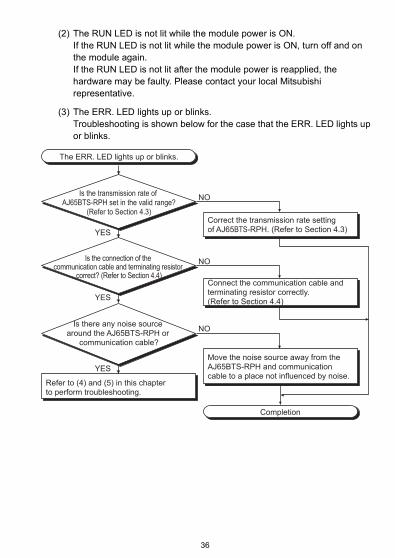
(2) The RUN LED is not lit while the module power is ON.If the RUN LED is not lit while the module power is ON, turn off and on the module again.If the RUN LED is not lit after the module power is reapplied, the hardware may be faulty. Please contact your local Mitsubishi representative.
(3) The ERR. LED lights up or blinks.Troubleshooting is shown below for the case that the ERR. LED lights up or blinks.
YES
YES
YES
NO
NO
NO
The ERR. LED lights up or blinks.
Completion
Is the transmission rate of AJ65BTS-RPH set in the valid range?
(Refer to Section 4.3)
Is the connection of the communication cable and terminating resistor
correct? (Refer to Section 4.4)
Is there any noise source around the AJ65BTS-RPH or
communication cable?
Refer to (4) and (5) in this chapter to perform troubleshooting.
Correct the transmission rate setting of AJ65BTS-RPH. (Refer to Section 4.3)
Connect the communication cable and terminating resistor correctly. (Refer to Section 4.4)
Move the noise source away from the AJ65BTS-RPH and communication cable to a place not influenced by noise.
36
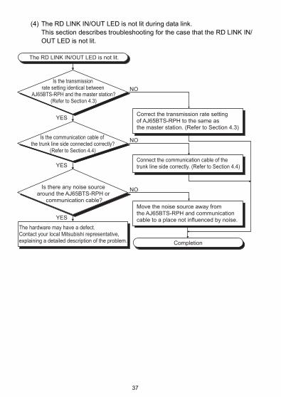
(4) The RD LINK IN/OUT LED is not lit during data link.This section describes troubleshooting for the case that the RD LINK IN/OUT LED is not lit.
YES
YES
YES
NO
NO
NO
The RD LINK IN/OUT LED is not lit.
Completion
Is the transmission rate setting identical between
AJ65BTS-RPH and the master station?(Refer to Section 4.3)
Is the communication cable of the trunk line side connected correctly?
(Refer to Section 4.4)
Is there any noise source around the AJ65BTS-RPH or
communication cable?
The hardware may have a defect. Contact your local Mitsubishi representative, explaining a detailed description of the problem.
Correct the transmission rate setting of AJ65BTS-RPH to the same as the master station. (Refer to Section 4.3)
Connect the communication cable of the trunk line side correctly. (Refer to Section 4.4)
Move the noise source away from the AJ65BTS-RPH and communication cable to a place not influenced by noise.
37
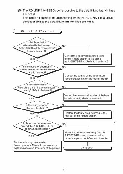
(5) The RD LINK 1 to 8 LEDs corresponding to the data linking branch lines are not lit.This section describes troubleshooting when the RD LINK 1 to 8 LEDs corresponding to the data linking branch lines are not lit.
YES
YES
NO
NO
NO
YES
NO
YES
YES
NO
RD LINK 1 to 8 LEDs are not lit
Completion
Is the transmission rate setting identical between
AJ65BTS-RPH and the remote station?(Refer to Section 4.3)
Is the setting of destination remote station set on the master
station correct?
Is the communication cable of the branch line side connected
correctly? (Refer to Section 4.4)
Is there any error on the remote station?
Is there any noise source around the AJ65BTS-RPH or
communication cable?
The hardware may have a defect. Contact your local Mitsubishi representative, explaining a detailed description of the problem.
Correct the transmission rate setting of the remote station to the same as AJ65BTS-RPH. (Refer to Section 4.3)
Correct the setting of the destination remote station set on the master station.
Connect the communication cable of the branch line side correctly. (Refer to Section 4.4)
Restore the faulty area referring to the manual of the remote station.
Move the noise source away from the AJ65BTS-RPH and communication cable to a place not influenced by noise.
38
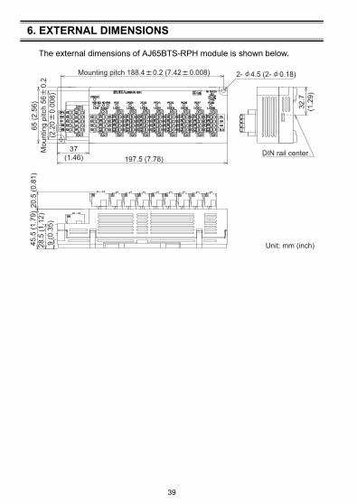
6. EXTERNAL DIMENSIONS
The external dimensions of AJ65BTS-RPH module is shown below.
32.7
(1.2
9)
Mounting pitch 188.4 0.2 (7.42 0.008)
37(1.46)
2- 4.5 (2- 0.18)
197.5 (7.78)
Unit: mm (inch)
65 (2
.56)
20.5
(0.8
1)28
.5 (1
.12)
45.5
(1.7
9)
9 (0
.35)
DIN rail centerMou
ntin
g pi
tch
56
0.2
(2.2
0
0.00
8)
39


WARRANTYMitsubishi will not be held liable for damage caused by factors found not to be the cause of Mitsubishi; machine damage or lost profits caused by faults in the Mitsubishi products; damage, secondary damage, accident compensation caused by special factors unpredictable by Mitsubishi; damages to products other than Mitsubishi products; and to other duties.
Specifications subject to change without notice.
HEAD OFFICE : TOKYO BUILDING, 2-7-3 MARUNOUCHI, CHIYODA-KU, TOKYO 100-8310, JAPANNAGOYA WORKS : 1-14, YADA-MINAMI 5-CHOME, HIGASHI-KU, NAGOYA, JAPAN
When exported from Japan, this manual does not require application to the Ministry of Economy, Trade and Industry for service transaction permission.
MITSUBISHI ELECTRIC TURKEY A.Ş Ümraniye Branch Serifali Mahallesi Nutuk Sokak No:5, TR-34775 Umraniye/Istanbul, TurkeyTel : +90-216-526-3990MITSUBISHI ELECTRIC EUROPE B.V. Dubai Branch Dubai Silicon Oasis, P.O.BOX 341241, Dubai, U.A.E.Tel : +971-4-3724716ADROIT TECHNOLOGIES 20 Waterford Office Park, 189 Witkoppen Road, Fourways, South AfricaTel : +27-11-658-8100
MITSUBISHI ELECTRIC AUTOMATION (CHINA) LTD. No.1386 Hongqiao Road, Mitsubishi Electric Automation Center, Shanghai, ChinaTel : +86-21-2322-3030SETSUYO ENTERPRISE CO., LTD. 6F, No.105, Wugong 3rd Road, Wugu District, New Taipei City 24889, TaiwanTel : +886-2-2299-2499MITSUBISHI ELECTRIC AUTOMATION KOREA CO., LTD. 7F-9F, Gangseo Hangang Xi-tower A, 401, Yangcheon-ro, Gangseo-Gu, Seoul 07528, KoreaTel : +82-2-3660-9530MITSUBISHI ELECTRIC ASIA PTE. LTD. 307, Alexandra Road, Mitsubishi Electric Building, Singapore 159943Tel : +65-6473-2308
MITSUBISHI ELECTRIC FACTORY AUTOMATION (THAILAND) CO., LTD. 12th Floor, SV.City Building, Office Tower 1, No. 896/19 and 20 Rama 3 Road, Kwaeng Bangpongpang, Khet Yannawa, Bangkok 10120, ThailandTel : +66-2682-6522MITSUBISHI ELECTRIC VIETNAM COMPANY LIMITED Hanoi Branch 6th Floor, Detech Tower, 8 Ton That Thuyet Street, My Dinh 2 Ward, Nam Tu Liem District, Hanoi, VietnamTel : +84-4-3937-8075PT. MITSUBISHI ELECTRIC INDONESIAGedung Jaya 11th Floor, JL. MH. Thamrin No.12, Jakarta Pusat 10340, IndonesiaTel : +62-21-3192-6461
MITSUBISHI ELECTRIC INDIA PVT. LTD. Pune Branch Emerald House, EL-3, J Block, M.I.D.C., Bhosari, Pune-411026, Maharashtra, IndiaTel : +91-20-2710-2000
USA MITSUBISHI ELECTRIC AUTOMATION, INC. 500 Corporate Woods Parkway, Vernon Hills, IL 60061, U.S.A.Tel : +1-847-478-2100
Turkey
Sales office/Tel
Country/Region
Sales office/Tel
Country/Region
Mexico MITSUBISHI ELECTRIC AUTOMATION, INC. Mexico Branch Mariano Escobedo #69, Col. Zona Industrial, Tlalnepantla Edo. Mexico, C.P.54030Tel : +52-55-3067-7500
UAE
Brazil MITSUBISHI ELECTRIC DO BRASIL COMÉRCIO E SERVIÇOS LTDA. Avenida Adelino Cardana, 293, 21 andar, Bethaville, Barueri SP, BrazilTel : +55-11-4689-3000
South Africa
Germany MITSUBISHI ELECTRIC EUROPE B.V. German Branch Mitsubishi-Electric-Platz 1, 40882 Ratingen, GermanyTel : +49-2102-486-0
China
UK MITSUBISHI ELECTRIC EUROPE B.V. UK Branch Travellers Lane, Hatfield, Hertfordshire, AL10 8XB, U.K.Tel : +44-1707-28-8780
Taiwan
Ireland MITSUBISHI ELECTRIC EUROPE B.V. Irish Branch Westgate Business Park, Ballymount, Dublin 24, IrelandTel : +353-1-4198800
Korea
Italy MITSUBISHI ELECTRIC EUROPE B.V. Italian Branch Centro Direzionale Colleoni-Palazzo Sirio Viale Colleoni 7, 20864 Agrate Brianza(Milano) ItalyTel : +39-039-60531
Singapore
Spain MITSUBISHI ELECTRIC EUROPE, B.V. Spanish Branch Carretera de Rubí, 76-80-Apdo. 420, 08190 Sant Cugat del Vallés (Barcelona), SpainTel : +34-935-65-3131
Thailand
France MITSUBISHI ELECTRIC EUROPE B.V. French Branch 25, Boulevard des Bouvets, 92741 Nanterre Cedex, FranceTel : +33-1-55-68-55-68
Vietnam
Czech Republic
MITSUBISHI ELECTRIC EUROPE B.V. Czech Branch Avenir Business Park, Radlicka 751/113e, 158 00 Praha5, Czech RepublicTel : +420-251-551-470
Indonesia
Poland MITSUBISHI ELECTRIC EUROPE B.V. Polish Branch ul. Krakowska 50, 32-083 Balice, PolandTel : +48-12-347-65-00
India
Sweden MITSUBISHI ELECTRIC EUROPE B.V. (Scandinavia) Fjelievägen 8, SE-22736 Lund, SwedenTel : +46-8-625-10-00
Russia MITSUBISHI ELECTRIC (RUSSIA) LLC St. Petersburg Branch Piskarevsky pr. 2, bld 2, lit “Sch”, BC “Benua”, office 720; 195027 St. Petersburg, RussiaTel : +7-812-633-3497
Australia MITSUBISHI ELECTRIC AUSTRALIA PTY. LTD.348 Victoria Road, P.O. Box 11, Rydalmere, N.S.W 2116, AustraliaTel : +61-2-9684-7777