Embed Size (px)
Citation preview

GCSE
CCEA GCSE SpecimenAssessment Materials for
Technology and Design
For first teaching from September 2017For first assessment in Summer 2018For first award in Summer 2019Subject Code: 8900


ForewordCCEA has developed new specifications which comply with criteria for GCSE qualifications. The specimen assessment materials accompanying new specifications are provided to give centres guidance on the structure and character of the planned assessments in advance of the first assessment. It is intended that the specimen assessment materials contained in this booklet will help teachers and students to understand, as fully as possible, the markers’ expectations of candidates’ responses to the types of tasks and questions set at GCSE level. These specimen assessment materials should be used in conjunction with CCEA’s GCSE Technology and Design specification.


GCSE Technology and DesignSpecimen Assessment Materials
Contents
Specimen Papers 3
Unit 1: Technology and Design Core Content 3Unit 2: Option A – Electronic and Microelectronic Control Systems 23Unit 2: Option B – Mechanical and Pneumatic Control Systems 41Unit 2: Option C – Product Design 59Unit 3: Controlled Assessment – Design and Manufacturing Project 77
Mark Schemes 81
General Marking Instructions 83Unit 1: Technology and Design Core Content 87Unit 2: Option A – Electronic and Microelectronic Control Systems 95Unit 2: Option B – Mechanical and Pneumatic Control Systems 105Unit 2: Option C – Product Design 111

Subject Code 8900
QAN 603/0771/7
A CCEA Publication © 2017
You may download further copies of this publication from www.ccea.org.uk

SPECIMEN PAPERS
DIVIDER FRONT

SPECIMEN PAPERS
DIVIDER BACK

Centre Number
Candidate Number
General Certificate of Secondary Education2018
For Examiner’s use only
Question Number
Marks
1
2
3
4
5
6
7
8
9
10
TotalMarks
TIME1 hour 30 minutes.
INSTRUCTIONS TO CANDIDATESWrite your Centre Number and Candidate Number in the spaces provided at the top of this page.You must answer the questions in the spaces provided. Do not write outside the boxed area on each page or on blank pages.*Questions which require drawing or sketching should be completed using an HB pencil. All written questions must be completed using blue or black ink only. Do not write in pencil or with a gel pen.
Answer all questions.
INFORMATION FOR CANDIDATESThe total mark for this paper is 100. Quality of written communication will be assessed in Question 10.Figures in brackets printed down the right-hand side of pages indicate the marks awarded to each question or part question. The Formula sheet is on Page 4.
*Relevant for live examinations only.
Technology and Design
Unit 1
Technology and Design Core Content
[CODE]SPECIMEN PAPER
3

Formulae for GCSE Technology and Design
You should use, where appropriate, the formulae given below when answering questions which include calculations.
1 Potential Difference = current × resistance (V = I × R)
2 Series Resistors Rt = R1 + R2 + ... +Rn
3 Gear ratio of a simple gear train = number of teeth on driven gearnumber of teeth on driver gear
4 Velocity Ratio = Diameter of drivenDiameter of driver
4

Examiner Only
Marks Re-mark
5
Answer all questions
1 Table 1 shows a number of symbols.
(a) Using the first row as a guide, complete the table below.
Table 1
[3]
(b) Table 1 above shows a symbol for a bulb. This component produces light in an electronic circuit. Give another example of an electronic output component and state its output.
Electronic Component [1]
Output [1]
Examiner Only
Marks Re-mark
6
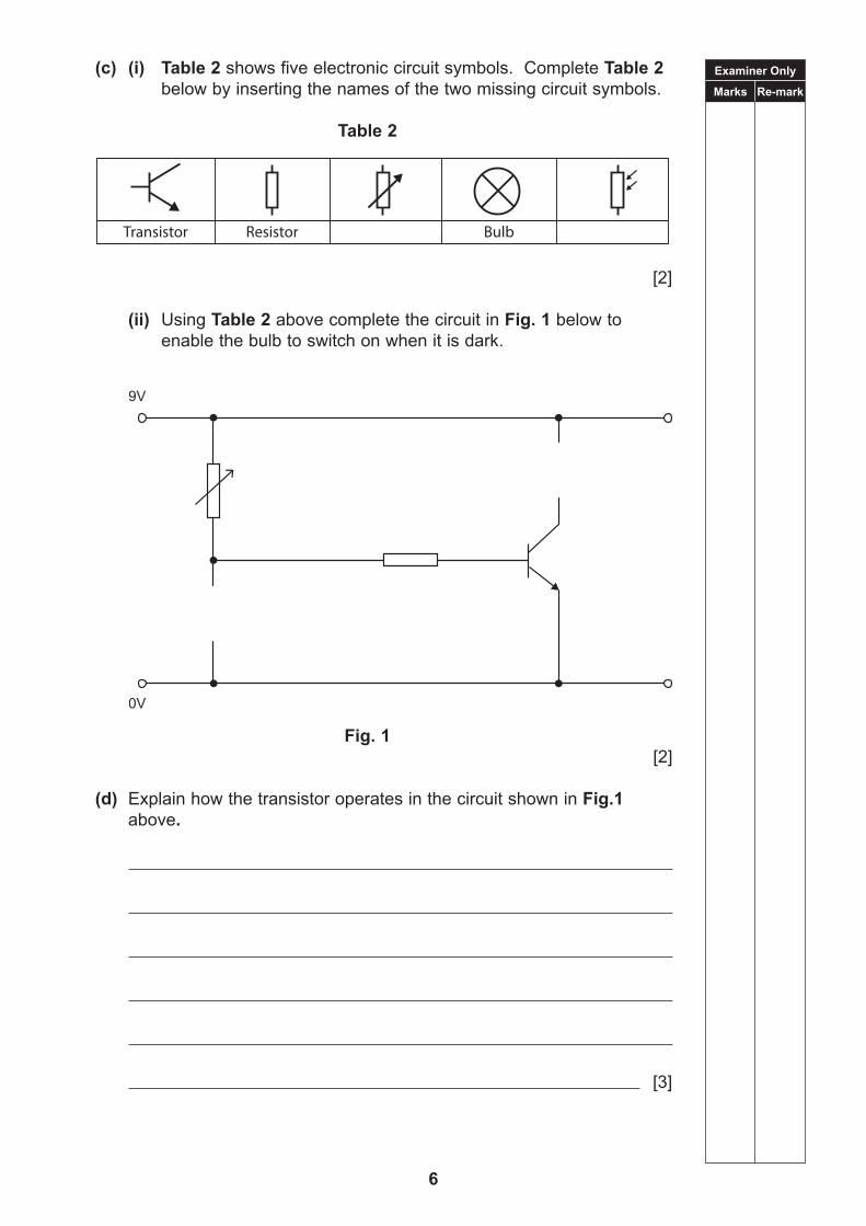
(c) (i) Table 2 shows five electronic circuit symbols. Complete Table 2 below by inserting the names of the two missing circuit symbols.
Table 2
[2]
(ii) Using Table 2 above complete the circuit in Fig. 1 below to enable the bulb to switch on when it is dark.
Fig. 1 [2]
(d) Explain how the transistor operates in the circuit shown in Fig.1 above.
[3]

Examiner Only
Marks Re-mark
7
2 (a) Fig. 2 below shows a sliding bevel made in a school workshop. The blade has been produced using a CAD/CNC process.
(i) What do the letters CAD and CNC stand for?
CAD [1]
CNC [1]
(ii) State one advantage and one disadvantage of using CNC to manufacture the blade compared to using hand tools.
Advantage [1]
Disadvantage [1]
(iii) Explain three stages of the CAD/CNC process used to manufacture the blade shown in Fig 2 above.
[3]
Fig. 2© CCEA

Examiner Only
Marks Re-mark
8
(b) The two materials used in the manufacture of the sliding bevel are mild steel and aluminium alloy.
(i) Is mild steel a ferrous or non-ferrous metal?
[1]
(ii) Is aluminium alloy a ferrous or non-ferrous metal?
[1]
(c) The blade in Fig 2. on the previous page shows an inner slot that has been cut out. Describe five stages in the marking out process of the inner slot, if this slot was cut using hand tools and a pillar drill.
[5]

Examiner Only
Marks Re-mark
9
3 Fig. 3 below shows a belt drive connecting a motor to a machine.
Fig. 3
(a) Name the type of belt shown in Fig. 3 above.
[1]
(b) State the type of motion of the motor pulley shown in Fig. 3 above.
[1]
(c) State the type of motion of the belt between the motor and machine pulley shown in Fig. 3 above.
[1]
(d) Describe how the pulley system in Fig. 3 above could be modified to slow down the speed of the machine pulley for the same motor speed.
[2]

Examiner Only
Marks Re-mark
10
(e) Another method of connecting the motor to a machine is to use a chain and sprocket system. Compare and contrast the suitability of this system to the pulley system shown in Fig. 3 above.
[2]

Examiner Only
Marks Re-mark
11
4 Fig. 4 below shows a diagram of a pneumatic circuit.
Fig. 4
(a) Name component D in Fig. 4 above.
[1]
(b) Outline the two methods which can be used to make component D outstroke.
1 [1]
2 [1]
(c) Name component E in Fig. 4 above and describe a main function of this component.
Name [1]
Function
[2]

Examiner Only
Marks Re-mark
12
5 (a) Complete Table 3 below by inserting a tick () in the appropriate column to show if the wood is a hardwood, softwood or manufactured board.
Table 3
Material Hardwood Softwood Manufactured board
Mahogany
Chipboard
Beech
Pine
Cedar
[5]
(b) (i) Complete Table 4 by inserting a tick () in the appropriate column to show if the plastic is a thermoplastic or a thermosetting plastic.
Table 4
Material Thermoplastic Thermosetting plastic
Rigid polystyrene
Melamine
Acrylic
Epoxy resin
[4]
(ii) Explain the difference between a thermoplastic and a thermosetting plastic.
[2]

Examiner Only
Marks Re-mark
13
6 Fig. 5 below shows a resistor and an LED. These two components are commonly used together in electronic circuits.
(a) In the space below, draw the electronic symbol for an LED.
[2]
(b) Explain why a resistor and an LED are commonly used together in an electronic circuit.
[2]
Fig. 5© CCEA

Examiner Only
Marks Re-mark
14
(c) Fig. 6 below shows part of an electronic circuit. Calculate the value of the current flow if the voltage is 9V and the resistor has a value of 330 ohms.
Fig. 6
Candidates need to show their working out in the space below.
Answer [3]
(d) Fig. 7 below shows a circuit which is used to control output voltage.
Fig. 7
Name the type of circuit shown in Fig. 7 below.
[1]

Examiner Only
Marks Re-mark
15
7 Fig. 8 below shows model traffic lights used in a toy car racing track.
Fig. 8
In this system, only one light will be on at any one time. When a new light comes on, the previous one switches off automatically.
When the switch is pressed, the red light comes on. Ten seconds later, the red light goes off and the amber light comes on for five seconds, then goes off. The green light then comes on for 15 seconds and then switches off. The program then stops.
Complete the flowchart in Fig. 9 on the next page.
© CCEA

Examiner Only
Marks Re-mark
16
Fig. 9 [9]

Examiner Only
Marks Re-mark
17
8 (a) Complete Table 5 below by inserting a tick () in the appropriate column to show if the product is a first, second or third class lever.
Table 5
Products First class lever
Second class lever
Third class lever
See-saw
Bottle opener
[2]
(b) Fig. 10 below shows three classes of levers. Identify each lever by its class.
(i)
Class of lever [2]
(ii)
Class of lever [2]
(iii)
Fig. 10
Class of lever [2]

Examiner Only
Marks Re-mark
18
(c) Fig. 11 below shows a wheelbarrow. When the wheelbarrow is loaded it is very heavy to lift.
Fig. 11
(i) Suggest two modifications to the design of the wheelbarrow shown in Fig. 11 above, which would make it easier to lift the same load without changing the materials.
1 [1]
2 [1]
(ii) Analyse the wheelbarrow in Fig. 11 above to describe where the load, fulcrum and effort is applied.
[3]
© CCEA

Examiner Only
Marks Re-mark
19
9 (a) Complete Table 6 below by naming the pneumatic symbols.
Table 6
[4]
(b) Fig. 12 shows a pneumatic circuit.
Fig. 12
(i) Explain how the circuit in Fig. 12 above can be modified, so that component C can remain in the outstroke position.
[2]
2
3
1

Examiner Only
Marks Re-mark
20
(ii) Describe how the circuit in Fig. 12 on the previous page works.
[2]
(iii) Consider two modifications which could be introduced to Fig. 12 on the previous page, to increase the outstroke force.
[2]

Examiner Only
Marks Re-mark
21
10 You are asked to drill holes in a printed circuit board (PCB) and solder a resistor to this board.
Describe the process of drilling the holes and soldering a resistor to this board.
Appropriate safety precautions should be referred to throughout your description.
Quality of written communication will be assessed in this question.
[10]

THIS IS THE END OF THE QUESTION PAPER
22
Centre Number
Candidate Number
General Certificate of Secondary Education2019
For Examiner’s use only
Question Number
Marks
1
2
TotalMarks
TIME1 hour 30 minutes.
INSTRUCTIONS TO CANDIDATESWrite your Centre Number and Candidate Number in the spaces provided at the top of this page.You must answer the questions in the spaces provided. Do not write outside the boxed area on each page or on blank pages.*Questions which require drawing or sketching should be completed using an HB pencil. All written questions must be completed using blue or black in only.Do not write in pencil or with a gel pen.
Answer both questions
INFORMATION FOR CANDIDATESThe total mark for this paper is 100.Quality of written communication will be assessed in Question 1(d). Figures in brackets printed down the right-hand side of pages indicate the marks awarded to each question or part question.The Formula sheet is on Page 24.
*Relevant for live examinations only.
Technology and DesignUnit 2
Option A: Electronic and Microelectronic Control Systems
[CODE]SPECIMEN PAPER
23

24
Formulae for GCSE Technology and Design You should use, where appropriate, the formulae given below when answering questions which include calculations. 1 Potential Difference = current × resistance (V = I × R) 2 For potential divider
Vout = R2R1 + R2
× Vin
3 Series Resistors Rt = R1 + R2 + ⋯ + Rn
4 Parallel Resistors 21
111RRRt
or 21
21
RRRRRt
5 Time Constant T = R × C 6 Period T = 1
f
7 Frequency f = 1.44(R1+2R2)C for the output of an astable circuit using a 555 timer
8 Time T = 1.1 x C x R for the output of a monostable circuit using a 555 timer
Formulae for GCSE Technology and Design
You should use, where appropriate, the formulae given below when answering questions which include calculations.
1 Potential Difference = current × resistance (V = I × R)
2 For potential divider Vout = R2
(R1 + R2) × Vin
3 Series Resistors Rt = R1 + R2 + ... +Rn
4 Parallel Resistors 1Rt
= 1R1
+ 1R2
or Rt = R1 × R2
R1 + R2
5 Time Constant T = R × C
6 Period T =1f
7 Frequency (Hz) f = 1.44
(R1 + 2R2)C for the output of an astable circuit using a 555 timer
8 Time T = 1.1 × C × R for the output of a monostable circuit using a 55 timer

Examiner Only
Marks Re-mark
25
Answer all questions.
1 (a) A manufacturer produces resistors with values in either the E12 or E24 series.
(i) Explain the difference between these two series and give an advantage in being able to select a resistor from the E24 series compared to the E12 series.
[2]
The E24 series is shown in Table 1 below.
Table 1
1.0 1.1 1.2 1.3 1.5 1.6 1.8 2.0 2.2 2.4 2.7 3.0
3.3 3.6 3.9 4.3 4.7 5.1 5.6 6.2 6.8 7.5 8.2 9.1
(ii) A value of 770 Ω has been calculated for a resistor in a circuit. What is the nearest preferred value that is available from the E24 series?
[2]
(iii) Use the information below to identify the colours of the first three bands for a 5.1 kΩ resistor.
Resistor Colour Codes
0 = Black 1 = Brown 2 = Red 3 = Orange 4 = Yellow
5 = Green 6 = Blue 7 = Violet 8 = Grey 9 = White
Band 1 [1]
Band 2 [1]
Band 3 [1]

Examiner Only
Marks Re-mark
26
(iv) If the 5.1 kΩ resistor has a tolerance of 5%, calculate the minimum and maximum values that it may have.
Candidates need to show their working out in the space below.
Minimum Maximum [4]

Examiner Only
Marks Re-mark
27
(b) Fig. 1 below shows an incomplete circuit diagram. The circuit is to be completed by adding a semiconductor diode at position X.
Fig. 1
(i) At position X on Fig. 1, draw the circuit symbol for a diode so that the bulb should light when the switch is closed. [2]
(ii) State the essential feature of a diode.
[1]
(iii) Add a voltmeter to the circuit in Fig. 1 above, in order to measure the voltage across the bulb when it is lit. Label the + terminal of the meter.
[3]
(iv) Calculate the reading that you expect to obtain on the meter when the bulb is lit, assuming that the circuit in Fig. 1 above is functioning correctly.
Candidates need to show their working out in the space below.
Answer [2]

Examiner Only
Marks Re-mark
28
(c) Fig. 2 below shows an incomplete circuit diagram for a transistor circuit.
Fig. 2
(i) Complete the diagram by inserting the symbol for an LDR at position A in Fig. 2 above. [2]
(ii) Explain the operation of the circuit in Fig. 2 above.
[6]
(iii) What do the letters PCB stand for?
[1]

Examiner Only
Marks Re-mark
29
A pupil is manufacturing a PCB for the circuit shown in Fig. 2 on the previous page. The incomplete simulated PCB design is shown in Fig. 3 below.
Fig. 3
(iv) What material is used for the PCB track and why is this material used?
Material [1]
Reason For use
[1]
(v) Complete Fig. 3 above as follows:
• Draw the 1 kΩ and 22 kΩ resistors on the PCB design using the appropriate symbols and terminals, in suitable positions and label the resistors.
• Draw PCB tracks to connect the components so that the PCB connections are the same as in the circuit diagram in Fig. 2.
• Label the + battery terminal on the PCB board. [10]
PCB

Examiner Only
Marks Re-mark
30
(d) Robotic arms are widely used in manufacturing.
Discuss why microcontrollers are a good method of control for these machines.
Your answer should focus on five points.
Quality of written communication will be assessed in this question.
© Baloncici / iStock / Thinkstock

Examiner Only
Marks Re-mark
31
[10]

Examiner Only
Marks Re-mark
32
2 Fig. 4 shows a buggy which a student has designed and made. It is to be controlled using a Microcontroller (PIC). The buggy has two small motors attached to the wheels (Motor C and Motor D) to enable the buggy to move and a small wheel at the back for stability. The buggy is fitted with 2 micro switches to detect if the buggy comes into contact with an obstacle. When this happens, the buggy sounds an alarm and moves to avoid the obstacle.
Fig. 4
The PIC has 5 inputs (only 2 are used) and 8 outputs (only 7 are used).
Table 2 below shows the input connections for the buggy in Fig. 4 above:
Table 2
PIC INPUTS
BIT 4 3 2 1 0
front of buggy
(Not
use
d)
(Not
use
d)
Rig
ht M
icro
Sw
itch
(Not
use
d)
Left
Mic
ro
Switc
h

Examiner Only
Marks Re-mark
33
Table 3 below shows the output connections for the buggy in Fig. 4 on the previous page:
Table 3
PIC OUTPUTS
BIT 7 6 5 4 3 2 1 0
MOTOR FORWARD 0 1 0 1 X X X X
MOTOR REVERSE 1 0 1 0 X X X X
MOTOR STOP 0 0 0 0 X X X X
A binary 1 indicates high (on) and a binary 0 indicates low (off). An X means ignore. Two bits are required to control each motor.
(a) (i) Electronic systems may contain input, process and output devices. Which component on the buggy would on Fig. 4 on the previous page be classified as a process device?
Answer [1]
(ii) State an advantage that this process device would have compared with other process devices that could be used in the buggy.
Answer [1]
(iii) Complete the grid to show the bit pattern that would be used to check if the buggy collided with an obstacle which operated the left microswitch.
Bit pattern [2]
(iv) Complete the grid to show the bit pattern that would be needed to switch on both motors to cause the buggy to move forward, all other outputs being switched off.
Bit pattern [2]
(v) Convert the binary number 10011001 to decimal.
Answer [2]
Mot
or D
Mot
or C
Left
LED
Rig
ht L
ED
(Not
use
d)
Buz
zer
x x x
x

Examiner Only
Marks Re-mark
34
(vi) Convert the decimal number 19 to binary.
Answer [2]
(b) The main operating routine for the buggy is shown in the flow chart in Fig. 5 below.
Fig. 5
Each part of the system is built as separate macros.
(i) Give two reasons why a programmer would use separate macros rather than a continuous flowchart.
1
[2]
2
[2]

Examiner Only
Marks Re-mark
35
(ii) Complete the flowchart in Fig. 6 below to represent the MOVE macro in Fig. 5 on the previous page as follows:
• Move forward by turning on Motor C and Motor D.
• Is the left micro switch pressed? If not, is the right micro switch pressed? If not, the buggy continues to move forward.
• If either micro switch is pressed then stop the buggy by turning off both motors.
• End the sequence.
Fig. 6
[11]

Examiner Only
Marks Re-mark
36
(iii) Complete the flowchart in Fig. 7 below to represent the AVOID part of the flowchart in Fig. 5 on page 34 as follows:
• Both LEDs and the buzzer should come on for 1 second
• Reverse both motors for 2 seconds
• Stop both motors for 0.5 seconds
• Motor D goes forward and Motor C reverses at the same time for 1 second
• Stop both motors for 0.5 seconds
• End the sequence
Fig. 7
[10]
Examiner Only
Marks Re-mark
37
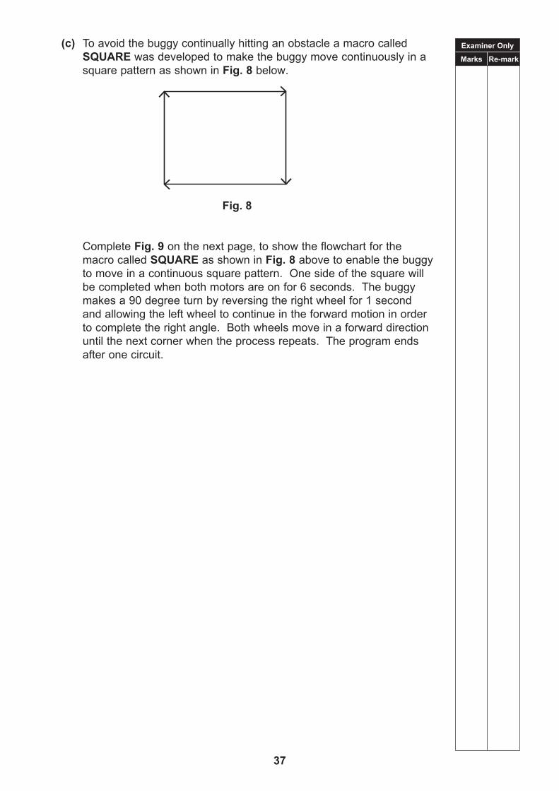
(c) To avoid the buggy continually hitting an obstacle a macro called SQUARE was developed to make the buggy move continuously in a square pattern as shown in Fig. 8 below.
Fig. 8
Complete Fig. 9 on the next page, to show the flowchart for the macro called SQUARE as shown in Fig. 8 above to enable the buggy to move in a continuous square pattern. One side of the square will be completed when both motors are on for 6 seconds. The buggy makes a 90 degree turn by reversing the right wheel for 1 second and allowing the left wheel to continue in the forward motion in order to complete the right angle. Both wheels move in a forward direction until the next corner when the process repeats. The program ends after one circuit.

Examiner Only
Marks Re-mark
38
Fig. 9 [10]
Fig. 9

Examiner Only
Marks Re-mark
39
(d) Tables 2 (pg 32) and 3 (pg 33) show the input and output connections to the PIC.
(i) The following bit pattern is received at the PIC from the inputs on the buggy. What has caused this bit pattern to be produced?
[2]
(ii) What action(s) would the following output bit pattern produce?
[3]
x x x 1 1
1 0 0 1 1 0 x 0

THIS IS THE END OF THE QUESTION PAPER
40

Centre Number
Candidate Number
General Certificate of Secondary Education2019
For Examiner’s use only
Question Number
Marks
1
2
TotalMarks
TIME1 hour 30 minutes.
INSTRUCTIONS TO CANDIDATESWrite your Centre Number and Candidate Number in the spaces provided at the top of this page.You must answer the questions in the spaces provided. Do not write outside the boxed area on each page or on blank pages.* Questions which require drawing or sketching should be completed using an H.B. pencil. All written questions must be completed using blue or black in only. Do not write in pencil or with a gel pen.
Answer both questions.
INFORMATION FOR CANDIDATESThe total mark for this paper is 100.Quality of written communication will be assessed in Question 2 (d).Figures in brackets printed down the right-hand side of pages indicate the marks awarded to each question or part question.The Formula sheet is on Page 42.
*Relevant for live examinations only.
Technology and Design
Unit 2
Option B: Mechanical and Pneumatic Control Systems
[CODE]SPECIMEN PAPER
41

42
Formulae for GCSE Technology and Design
You should use, where appropriate, the formulae given below when answering questions which include calculations.
1 Gear ratio of a simple gear train = number of teeth on driven gearnumber of teeth on driver gear
For a compound gear train: Total Gear ratio = the product of the gear ratios of all the subsystems i.e. GRT = GR1 × GR2 × GR3 ...
2 Velocity Ratio = Distance moved by effortDistance moved by load or Diameter of driven
Diameter of driver
3 Mechanical Advantage = LoadEffort
4 Efficiency (%) = bmechanical advantage
velocity ratiol × 100
5 Force = Pressure × Area (F = P × A)
6 Circumference of a circle = π × diameter

Examiner Only
Marks Re-mark
43
Answer all questions.
1 (a) Complete Table 1 below by naming the mechanical symbols.
Table 1
[4]

Examiner Only
Marks Re-mark
44
(b) Fig. 1 below shows a sketch of a gear system a student has constructed for use in a rotating display.
Fig. 1
(i) Which of the two gears shown in Fig. 1 above is the driver?
[1]
(ii) Give a reason for your answer.
[1]
(iii) Explain the difference between a simple and compound gear train.
[2]
(iv) Calculate the speed of the driven gear. Candidates need to show their working out in the space below.
Answer [2]

Examiner Only
Marks Re-mark
45
(c) The student decides to construct a second gear system for use in a rotating display. The sketch of the gear system is shown in Fig. 2 below.
Fig. 2
(i) Name the gear system shown in Fig. 2 above.
[1]
(ii) Calculate the gear ratio for this system. Candidates need to show their working out in the space below.
Answer [3]

Examiner Only
Marks Re-mark
46
(iii) Calculate the speed for the output gear D as shown on Fig. 2 on the previous page.
Candidates need to show their working out in the space below.
Answer [3]
(iv) The rotating display is to be used to exhibit a school trophy. Which of the two gear systems shown in Fig. 1 and Fig. 2 on the previous page should be used for the rotating display? Give a reason for your answer.
Gear System [1]
Reason
[2]

Examiner Only
Marks Re-mark
47
(d) A pulley system is shown in Fig. 3 below. The top pulley is fixed. The lower pulley is moveable.
(Assume that the ropes and pulleys are weightless and that the pulleys are frictionless.)
Fig. 3
(i) When the operator pulls the rope state the rotational direction of the lower pulley.
[2]
(ii) Calculate the distance moved by the effort when the load is lifted through a distance of 1 metre.
Candidates need to show their working out in the space below.
Answer [2]

Examiner Only
Marks Re-mark
48
(iii) What advantage does this pulley system (Fig. 3 previous page) offer compared with using a single fixed pulley to lift the load?
[2]
(iv) Calculate the velocity ratio of the system. Candidates need to show their working out in the space below.
Answer [2]
(v) Calculate the % efficiency of the system. Candidates need to show their working out in the space below.
Answer [6]

Examiner Only
Marks Re-mark
49
(vi) Sketch a new pulley system that has two fixed pulleys and one moveable pulley to lift the same load in Fig. 3 on page 47.
[6]

Examiner Only
Marks Re-mark
50
(vii) Given that the new pulley system has 3 pulleys, use two discussion points associated with this fact to compare the two systems.
[4]
(e) (i) A vee belt on a pulley system was found to be slipping. Explain how the belt could be adjusted to avoid slippage.
[2]
(ii) Outline two possible problems that belt slippage could cause in the drive system.
[2]
(iii) Name two other types of belt that are used in transmission systems.
1 [1]
2 [1]

Examiner Only
Marks Re-mark
51
2 Metal parts are to be dipped in a degreasing solution for a given time before painting. The pneumatic cylinder used in this process is shown in Fig. 4 below.
Fig. 4
(a) (i) Name the type of cylinder shown in Fig. 4 above.
[1]

Examiner Only
Marks Re-mark
52
(ii) The cylinder is required to raise a maximum load of 300N. Calculate the cross sectional area of the piston.
Supply pressure = 0.6 N/mm2.
Cross sectional area of the piston rod = 100mm2. Candidates need to show their working out in the space below.
[5]

Examiner Only
Marks Re-mark
53
(b) The pneumatic circuit used to control the cylinder in Fig. 4 on page 51 is shown in Fig. 5 below.
Fig. 5
(i) Outline the difference between component A and component F as shown on Fig. 5 above.
A [1]
F [1]
(ii) Outline the difference between a SAC and a DAC.
[2]
(iii) Describe how the circuit above operates.
Examiner Only
Marks Re-mark
54
[6]
(iv) State how each of the following could be changed:
• Increase the rate of immersion
[2]
• Increase the depth to which the parts are immersed
[2]
(v) The circuit in Fig. 5 on the previous page is to be modified so that the start signal can be given from either of two positions. Show on Fig. 5 on the previous page the connecting pipes and additional valves needed to achieve this. [6]

Examiner Only
Marks Re-mark
55
(c) Fig. 6 below shows a lifting device for packages. When a start button is operated for an instant the package is lifted by cylinder A. Cylinder B then pushes the package onto a gravity-roller conveyor. Both cylinders then return to their initial position.
Fig. 6
Part of the pneumatic circuit for Fig. 6 above is shown in Fig. 7 below.
(i) Complete the pneumatic circuit in Fig. 7 below by adding the pipework to give the required sequence.
Fig. 7
[8]

Examiner Only
Marks Re-mark
56
(ii) The circuit is to be modified so that the signal to outstroke cylinder A cannot be given unless cylinder B is fully retracted. Explain briefly how this could be achieved.
[4]

Examiner Only
Marks Re-mark
57
(d) Outline examples of three products that use pneumatic systems. In each case explain its function and why it is used in this application.
Quality of written communication will be assessed in this question.
Example 1
Example 2
Example 3
[12]

THIS IS THE END OF THE QUESTION PAPER
58

Centre Number
Candidate Number
General Certificate of Secondary Education2019
For Examiner’s use only
Question Number
Marks
1
2
3
4
5
6
7
8
TotalMarks
TIME1 hours 30 minutes.
INSTRUCTIONS TO CANDIDATESWrite your Centre Number and Candidate Number in the spaces provided at the top of this page.You must answer the questions in the spaces provided. Do not write outside the boxed area on each page or on blank pages.*Questions which require drawing or sketching should be completed using an H.B. pencil. All written questions must be completed using blue or black in only. Do not write in pencil or with a gel pen.
Answer all questions.
INFORMATION FOR CANDIDATESThe total mark for this paper is 100.Quality of written communication will be assessed in Question 8.Figures in brackets printed down the right-hand side of pages indicate the marks awarded to each question or part question.
*Relevant for live examinations only.
Technology and Design
Unit 2
Option C: Product Design
[CODE]SPECIMEN
59

Examiner Only
Marks Re-mark
60
Answer all questions
1 (a) (i) Name the symbol shown in Fig. 1 below.
Name [1]
(ii) Give two reasons why this symbol is identified on a product.
1
[1]
2
[1]
(b) Risk assessment is associated with potential hazards, personal safety and prevention. Discuss three potential hazards associated with using a pillar drill.
1
[2]
2
[2]
3
[2]
KITEMARK and the BSI Kitemark device are reproduced with kind permission of The British Standards Institution. They are registered trademarks in the
United Kingdom and in certain other countries
Fig. 1

Examiner Only
Marks Re-mark
61
2 Fig. 2 below shows the Product Life Cycle chart for a product.
Fig. 2
(a) Name the five stages identified on the graph in Fig. 2 above.
A [1]
B [1]
C [1]
D [1]
E [1]
(b) Fig. 3 below shows a Rubix cube.
Fig. 3
Products can be based on needs or wants. Is the Rubix cube based on a need or want?
[1]
Rubik’s Cube ® used by permission of Rubik’s Brand Ltd www.rubiks.com

Examiner Only
Marks Re-mark
62
(c) Outline four characteristics associated with the final stage of a product’s life cycle.
1 [1]
2 [1]
3 [1]
4 [1]
3 (a) Name two manufacturing processes carried out by robots in the manufacture of a car.
1 [1]
2 [1]
(b) Discuss three reasons why robotics is commonplace in manufacturing.
1
[2]
2
[2]
3
[2]

Examiner Only
Marks Re-mark
63
(c) Give two reasons why a company may be reluctant to introduce robotics for production.
1
[1]
2
[1]

Examiner Only
Marks Re-mark
64
4 Fig. 4 below is a stainless steel watering can produced and designed by Edward Barber and Jay Osgerby.
Fig. 4
(a) (i) Form and function are two features in product design. Does form follow function or does function follow form in the product shown in Fig. 4 above?
[1]
(ii) Look at the watering can in Fig. 4 above and describe two features that may be associated with its design.
1
[1]
2
[1]
(b) Give a reason to suggest why the watering shown in Fig. 4 above can would not be mass produced.
[1]
© Copyright Barber Osgerby Ltd

Examiner Only
Marks Re-mark
65
(c) Outline five facts associated with the design work of Edward Barber and Jay Osgerby.
1
[1]
2
[1]
3
[1]
4
[1]
5
[1]
Examiner Only
Marks Re-mark
66
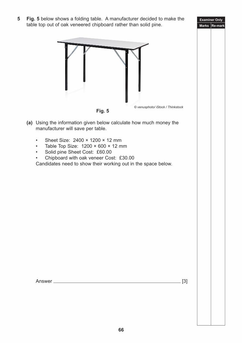
5 Fig. 5 below shows a folding table. A manufacturer decided to make the table top out of oak veneered chipboard rather than solid pine.
Fig. 5
(a) Using the information given below calculate how much money the manufacturer will save per table.
• Sheet Size: 2400 × 1200 × 12 mm• Table Top Size: 1200 × 600 × 12 mm • Solid pine Sheet Cost: £60.00• Chipboard with oak veneer Cost: £30.00
Candidates need to show their working out in the space below.
Answer [3]
© venusphoto/ iStock / Thinkstock

Examiner Only
Marks Re-mark
67
(b) (i) The frame of the table is made of galvanized tubular square section mild steel. Give two reasons other than cost why galvanized tubular square section mild steel is used.
1
[1]
2
[1] (ii) Sketch a cross section view of galvanized tubular square section mild steel in the space below.
[2]
(iii) Calculate the cross sectional area of the tubular material. The square section measures 20 mm × 20 mm and the material is
2 mm thick. Candidates need to show their working out in the space below.
Answer [3]

Examiner Only
Marks Re-mark
68
(c) Look at Fig. 5 on the previous page. Using clear annotated sketches and construction detail in the space below, show: • how the table could be modified to improve its stability• a clear method of attaching the table top to the frame
[10]
Examiner Only
Marks Re-mark
69
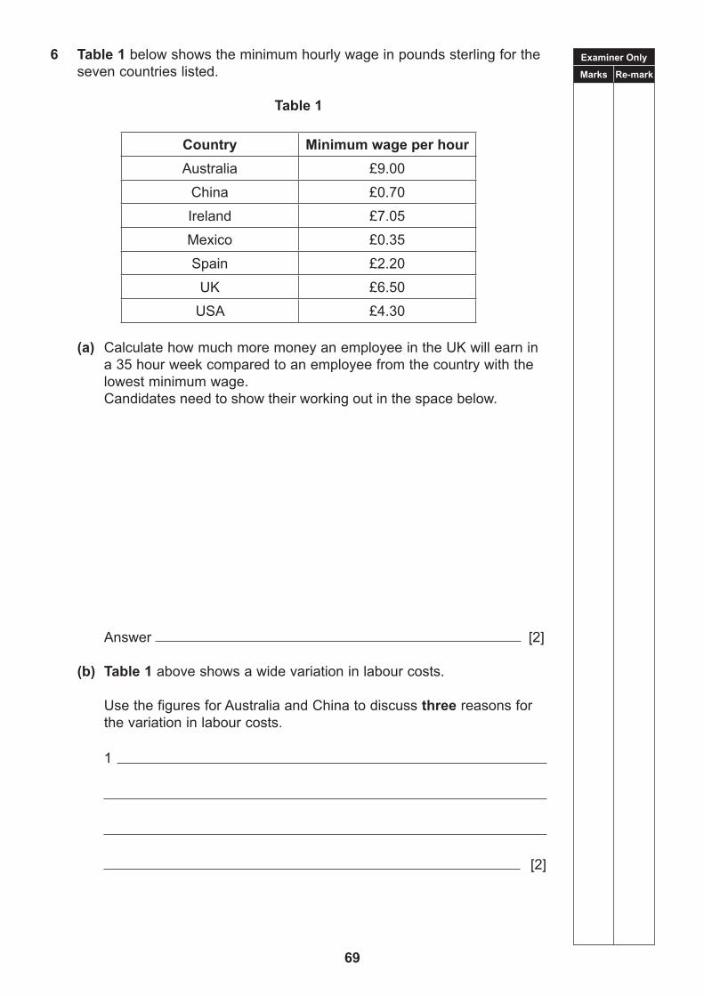
6 Table 1 below shows the minimum hourly wage in pounds sterling for the seven countries listed.
Table 1
Country Minimum wage per hourAustralia £9.00
China £0.70
Ireland £7.05
Mexico £0.35
Spain £2.20
UK £6.50
USA £4.30
(a) Calculate how much more money an employee in the UK will earn in a 35 hour week compared to an employee from the country with the lowest minimum wage.
Candidates need to show their working out in the space below.
Answer [2]
(b) Table 1 above shows a wide variation in labour costs. Use the figures for Australia and China to discuss three reasons for the variation in labour costs.
1
[2]

Examiner Only
Marks Re-mark
70
2
[2]
3
[2]
(c) A survey was carried out to identify the countries that imported a specific product from the UK. Use the information in Table 2 below to answer the following questions.
Table 2
Country Number of products imported (millions)
Australia 5
China 19
Ireland 7
Mexico 16
Spain 12
India 15
USA 6
(i) Interpret the data given and identify the country that has the most imports.
[1]
(ii) How many countries have imports of less than 10 million?
[1]
(iii) Calculate the total number of products exported from the UK.
[2]

Examiner Only
Marks Re-mark
71
7 Fig. 6, Fig. 7 and Fig. 8 below show how televisions have evolved with time.
(a) Describe one aspect of the function and one aspect of aesthetics
associated with the development of the television. State the influence of each of these developments.
Function
[1]
Influence
[1]
Aesthetics
[1]
Influence
[1]
© Ivansmuk/iStock/Thinkstock
Fig. 6
© scanrail/iStock/Thinkstock
Fig. 7
© geargodz/iStock/Thinkstock
Fig. 8
Examiner Only
Marks Re-mark
72
(b) Modern televisions like the one shown in Fig. 7 on the previous page have many additional uses in comparison to the television shown in Fig. 6 on the previous page. Outline two additional uses.
1 [1]
2 [1]
(c) (i) Anthropometric data is applied to many products. What is anthropometric data?
[1]
(ii) Suggest three features of the remote control as shown in Fig. 8 on the previous page which are based on anthropometric data.
1 [1]
2 [1]
3 [1]

Examiner Only
Marks Re-mark
73
8 Using an annotated sketch or sketches, design a freestanding holder for a teenager’s study desk that will accommodate A4 pages and other small stationery items.
The design solution should show evidence of the following features: • Good quality annotated sketches giving consideration to line, shape,
form and proportion. The annotated sketches should clearly convey your design thinking.
• Hold up to 100 A4 sheets of paper which measure 300 mm × 210 mm × 25 mm and hold the following other small stationery items 4 pens, 2 pencils, one pack of Post-it notes and one 300 mm ruler.
• Be free standing and able to sit on the desk.• Be aesthetically pleasing and suitable for teenagers.• Include three key dimensions.• Identify and justify the choice and use of materials.• Identify and justify the main manufacturing techniques used in the
design’s construction. [20]
Use the following 2 pages for your answer.
Quality of written communication will be assessed in this question.

74
Answer Page

75
Answer Page

THIS IS THE END OF THE QUESTION PAPER
76

Technology and Design
SPECIMEN
Unit 3
Controlled Assessment Task
Design and Manufacturing Project
General Certificate of Secondary Education2018
77
You have approximately 40 hours to complete the task.
The design portfolio should be maximum of ten A3 sheets one side only or equivalent.
All text should be size 12. Titles should not exceed size 16.
Students can present the portfolio in an electronic format.
Quality of written communication will be assessed throughout the design portfolio.
INSTRUCTIONS FOR THE CONTROLLED ASSESSMENT TASK
Candidates’ work to be submitted May 2019
Controlled Assessment Tasks must comply with the requirements as detailed in the subject specification.
NB: Some Controlled Assessment Tasks instructions may constitute more than 1 page. Please have all the information you need to complete the task if printing from a computer.

78
Unit 3: Design and Manufacturing Project
Instructions for teachers and students
This unit is compulsory for all students.
The Design Portfolio (25% of the full qualification)
The design portfolio should be a maximum of ten A3 sheets on one side only or equivalent. All text should be size 12. Titles should not exceed size 16.
Students may present the portfolio in an electronic format.
Students should understand that the design process is non-linear and creativity should be evident throughout the process.
The design portfolio is an integral part of the design project. Each design project will have its own characteristics and relevant processes but all design portfolios should include the following:
• a chosen theme and design brief;• a description and understanding of the design opportunity/problem;• research and analysis of products/Target Market Groups (TMGs) as appropriate to the
design opportunity/problem;• freehand sketching and CAD – these must be in all design portfolios;• specifications which identify key design criteria;• an appropriate range of freehand concept sketches;• an appropriate range of graphical techniques;• clear and succinct annotation;• evidence of creative thinking, problem solving and decision making; • the development of the concept(s) using freehand sketches and/or CAD/computer
modelling;• information on how the proposed solution may perform/improve considering to function,
form, size, ergonomics, safety and sustainability as appropriate;• manufacturing and assembly details of the proposed solution; • evidence of a physical model/mock-up to aid development of proposed solution;• working drawing(s) showing all of the necessary details for manufacture of the key parts;
and• evidence of testing and evaluation of the final solution to include appropriate modifications.
Quality of written communication will be assessed throughout the portfolio.

79
Manufacturing (25% of the full qualification)
The manufactured solution should be functional and be appropriately presented.
Students should understand that the design process is non-linear and creativity should be evident through the process.
The solution should have:
• scaled physical model(s) which relate(s) to and convey(s) a clear understanding of the final solution, proportion, form and function;
• evidence of the function and form of the prototype;• appropriate materials and fabrication techniques; • evidence of skills, precision, quality of manufacture, finish and attention to detail;• evidence of working under test conditions;• evidence of safety having been taken into account in its final construction and use;• evidence of templates, patterns, jigs and formers where appropriate to assist in production;
and• evidence of creativity.
Students are expected to demonstrate design capability, creativity and innovation using hand and CNC manufacturing skills where appropriate in the production and outcome of all model(s) and final prototype.
The design and manufacturing project carries a weighting of 50% of the full qualification and has an approximate time guidance of 40 hours.
Candidates must not exceed the 10 A3 page limits for the portfolio component of this unit.
In each design and manufacturing project the design portfolio carries 25% and the manufactured project carries 25% of the full qualification.
Themes
Candidates entering this component in the summer of 2019 series must choose one of the following themes.
Theme 1
The Charity Sector
The charity sector faces many difficult challenges. Attracting new donors, raising awareness, recruiting volunteers and organising events requires the generosity of the public in terms of both money and time.
Theme 2
Sporting Activities
Sporting activities and ideas are influenced by prestigious events e.g. the olympics, paralympics. Sport promotes healthy lifestyles and social interaction that has enormous benefits for society.

BLANK PAGE
80

81
MARK SCHEMESDIVIDER FRONT

82
MARK SCHEMESDIVIDER BACK
General Certificate of Secondary Education
GENERAL MARKING INSTRUCTIONS
Technology and Design
83

84
General Marking Instructions
IntroductionMark schemes are intended to ensure that the GCSE examinations are marked consistently and fairly. The mark schemes provide markers with an indication of the nature and range of candidates’ responses. The mark schemes should be read in conjunction with these general marking instructions.
Assessment objectivesBelow are the assessment objectives for GCSE Technology and Design.
Candidates must:
AO1 Recall, select and communicate their knowledge and understanding of Technology and Design in a range of contexts;
AO2 Apply skills knowledge and understanding, including quality standards in a variety of design contexts. Plan and carry out investigations and making tasks involving an appropriate range of tools, equipment, materials and processes; and
AO3 Analyse and evaluate evidence, design proposals and outcomes, make reasoned judgements and present conclusions and recommendations.
Quality of candidates’ responsesIn marking the examination papers, examiners should be looking for a quality of response reflecting the level of maturity which may reasonably be expected of a 16-year-old which is the age at which the majority of candidates sit their GCSE examinations.
Flexibility in markingMark schemes are not intended to be totally prescriptive. No mark scheme can cover all the responses which candidates may produce. In the event of an unanticipated answer, examiners are expected to use their professional judgement to assess the validity of answers. If an answer is particularly problematic, then examiners should seek the guidance of the Supervising Examiner.
Positive MarkingExaminers are encouraged to be positive in their marking, giving appropriate credit for what candidates know, understand and can do rather than penalising candidates for errors or omissions. Examiners should make use of the whole of the available mark range for any particular question and be prepared to award full marks for a response which is as good as might reasonably be expected of a 16-year-old GCSE candidate.
Awarding zero marksMarks should only be awarded for valid responses and no marks should be awarded for an answer which is completely incorrect or inappropriate.
Types of mark schemesMark schemes for tasks or questions which require candidates to respond in extended written form are marked on the basis of levels of response which take account of the quality of written communication.
Other questions which require only short answers are marked on a point for point basis with marks awarded for each valid piece of information provided.

85
Levels of responseTasks and questions requiring candidates to respond in extended writing are marked in terms of levels of response. In deciding which level of response to award, examiners should look for the ‘best fit’ bearing in mind that weakness in one area may be compensated for by strength in another. In deciding which mark within a particular level to award to any response, examiners are expected to use their professional judgement. The following guidance is provided to assist examiners.
• Threshold performance: Response which just merits inclusion in the level and should be awarded a mark at or near the bottom of the range.
• Intermediate Performance: Response which clearly merits inclusion in the level and should be awarded a mark at or near the middle of the range.
• High Performance: Response which fully satisfies the level description and should be awarded a mark at or near the top of the range.
Marking calculationsIn marking answers involving calculations, examiners should apply the “own figure rule” so that candidates are not penalised more than once for a computational error.
Quality of written communicationQuality of written communication is taken into account in assessing candidates’ responses to all tasks and questions that require them to respond in written form. These tasks and questions are marked on the basis of levels of response. The description for each level of response includes reference to the quality of written communication.
For conciseness, quality of written communication is distinguished within levels of response as follows:
Level 1: Quality of written communication is limited.Level 2: Quality of written communication is satisfactory.Level 3: Quality of written communication is very good.
In interpreting these level descriptions, examiners should refer to the more detailed guidance provided below:
Level 1 (Limited): The level of accuracy of presentation, spelling, punctuation and grammar is limited. The candidate makes a limited selection and use of an appropriate form and style of writing. The organisation of material may lack clarity and coherence. There is little use of specialist vocabulary.
Level 2 (Satisfactory): The level of accuracy of presentation, spelling, punctuation and grammar is satisfactory. The candidate makes a satisfactory selection and use of an appropriate form and style of writing supported with appropriate use of diagrams as required. Relevant material is organised with some clarity and coherence. There is some use of specialist vocabulary.
Level 3 (Very Good): The level of accuracy of presentation, spelling, punctuation and grammar is very good. The candidate successfully selects and uses the most appropriate form and style of writing, supported with precise and accurate use of diagrams where appropriate. Organisation of relevant material is very good. There is very good use of appropriate specialist vocabulary.

BLANK PAGE
86

MARKSCHEME
Technology and Design
[CODE]SPECIMEN
Unit 1
Technology and Design Core Content
General Certificate of Secondary Education2018
87

AVAILABLE MARKS
88
1 (a) First aid Flow chart
[3]
(b) Any one from the list below: • Buzzer [1] Sound [1] • Light emitting diode [1] Light [1] • Motor [1] Movement/Rotation [1] [2]
(c) (i) Variable resistor [1] Light dependent resistor [1] [2]
(ii) Symbol for light dependent resistor shown in the correct location [1] Symbol for bulb shown in the correct location [1] [2]
(d) It will only operate in dark conditions [1] When small current flows into the base the transistor will operate and switch on the bulb [1]
The transistor will operate when a voltage of approximately 0.7 volts is applied at the base [1] (Accept between ≥ 0.6 and ≤ 0.8.) [3]
Correct alternative responses will be considered.
2 (a) (i) Computer Aided Design [1] Computer Numerical Control [1] [2]
(ii) Any one of the following: Advantage: Increased speed [1] Repeat operations [1] Accuracy [1] [1]
Any one of the following: Disadvantage: Requires knowledge of software [1] Expensive to set up [1] [1]
Correct alternative responses will be considered.
12

AVAILABLE MARKS
89
(iii) Draw the blade on the computer using CAD software package [1] Simulation [1] Download the computer file used to make blade on CNC machine [1] [3]
Correct alternative responses will be considered. (b) (i) Ferrous [1]
(ii) Non-Ferrous [1] (c) Use engineer’s markers blue [1] Use odd-leg callipers to produce
a centre line [1] Use an engineering square, rule and scriber to determine end points of the slot [1] Use centre punch to mark two end points for drilling [1] Mark and draw the width of the slot using odd-leg callipers [1] [5]
Correct alternative responses will be considered.
3 (a) Vee belt [1]
(b) Rotary [1]
(c) Linear [1]
(d) Any one of the following: A larger machine pulley [2] or a smaller motor pulley [2]
(1 × [2]) [2]
(e) The vee belt system is not a positive drive it can slip [1] compared to the chain and sprocket which will not slip [1]
or
The belt drive system does not need lubrication [1] compared to the chain and sprocket which does need lubrication [1] [2]
Correct alternative responses will be considered.
4 (a) Single Acting Cylinder (SAC) [1]
(b) Press A AND B [1] Press C [1] [2]
(c) Shuttle Valve [1]
The shuttle valve directs air to the SAC [1] sending the piston positive [1] or The shuttle valve stops air escaping [1] through exhaust port 3 of C [1] or The shuttle valve stops air escaping [1] through exhaust port of B [1]
[3]
14
7
6
AVAILABLE MARKS
90
5 (a) Mahogany: hardwood Chipboard: manufactured board Beech: hardwood Pine: softwood Cedar: softwood (5 × [1]) [5]
(b) (i) Rigid Polystyrene: thermoplastic Melamine: thermosetting plastic Acrylic: thermoplastic Epoxy resin: thermosetting plastic (4 × [1]) [4]
(ii) Thermoplastic: can be reshaped by heating [1] Thermosetting plastic: once moulded, it remains rigid; cannot be reshaped by heating [1] [2]
6 (a)
Fully complete symbol for two marks. If wrong no marks [2]
(b) The LED must have a protective resistor [1] or The resistor limits the current into the LED and prevents damage to it [2] [2]
Correct alternative responses will be considered. (c) Calculation: V = I × R I = V ÷ R [1] I = 9 ÷ 330 [1] I = 0.027 or 0.03amps [1] or
Ans: 0.027 or 0.03amps [3] [3] (d) Potential divider [1] or voltage divider [1] [1]
11
8

AVAILABLE MARKS
91
7
Clarity of the flow chart and symbols [2] 9
AVAILABLE MARKS
92
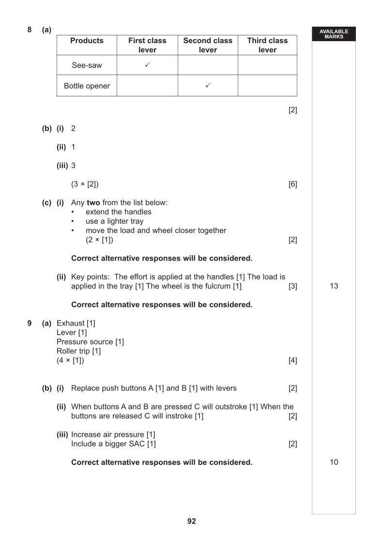
8 (a) Products First class
leverSecond class
leverThird class
lever
See-saw
Bottle opener
[2]
(b) (i) 2
(ii) 1
(iii) 3
(3 × [2]) [6]
(c) (i) Any two from the list below: • extend the handles • use a lighter tray • move the load and wheel closer together
(2 × [1]) [2]
Correct alternative responses will be considered.
(ii) Key points: The effort is applied at the handles [1] The load is applied in the tray [1] The wheel is the fulcrum [1] [3]
Correct alternative responses will be considered.
9 (a) Exhaust [1] Lever [1] Pressure source [1] Roller trip [1] (4 × [1]) [4]
(b) (i) Replace push buttons A [1] and B [1] with levers [2]
(ii) When buttons A and B are pressed C will outstroke [1] When the buttons are released C will instroke [1] [2]
(iii) Increase air pressure [1] Include a bigger SAC [1] [2]
Correct alternative responses will be considered.
13
10

AVAILABLE MARKS
93
10 Indicative Content:
• Make sure the board is secure/held with hand clamp• Drill holes using a PCB drill • Make sure the tracks are clean • Put resistor legs through holes on the PCB• Ensure resistor is flat on the PCB • Tin the soldering iron bit • Place the soldering iron bit on the PCB and resistor leg • Remove the solder wire before you remove the soldering iron• Allow time for the solder to solidify • Check joint is electrically and mechanically sound• Repeat soldering process for the other resistor leg• Use wire cutters to cut legs off resistor
Safety Precautions:
• Tie long hair back• Wear an apron to ensure there is no loose clothing• Wear goggles when using PCB drill• Keep hands away from the drill bit and chuck• One person operating the PCB drill • Switch off the PCB drill when finished• Use PCB drill with care when drilling• Keep hands away from the element and tip of soldering iron• Keep iron in stand when not in use
The safety precautions should be referred to throughout the indicative content. [10]
Correct alternative responses will be considered.

AVAILABLE MARKS
94
ResponseType Description Mark
Band
When a response is not worthy of credit [0] should be awarded
Limited
Students identify very few steps in the PCB drilling and soldering processes.
Very little or no safety precautions referred to throughout the answer.
The level of annotation conveys limited information and lacks technical vocabulary and specialist terms.
The accuracy of spelling, punctuation and grammar is limited.
[1]–[3]
Satisfactory
Students identify most of the steps in the PCB drilling and soldering processes, most of which are in order.
Some safety precautions referred to throughout the answer.
The level of annotation is satisfactory and contains some technical vocabulary and specialist terms.
The accuracy of spelling, punctuation and grammar is satisfactory.
[4]–[7]
Very good
Students correctly identify all the steps in the PCB drilling and soldering processes and in order.
Most of the safety precautions referred to throughout the answer.
The level of annotation and technical vocabulary and specialist terms is generally very good.
The accuracy of spelling, punctuation and grammar is very good.
[8]–[10]
Total 100
10

MARKSCHEME
Technology and Design
[CODE]SPECIMEN
General Certificate of Secondary Education2019
95
Unit 2
Option A: Electronic and Microelectronic Control Systems

AVAILABLE MARKS
96
1 (a) (i) The E12 series has 12 values per decade. The E24 series has 24 values per decade. [1] There are more values to choose from or it is possible to obtain a closer match to the desired value. [1]
[2]
(ii) 750 [1] Ω [1] [2]
(iii) Green [1] Brown [1] Red [1] (3 × [1]) [3]
(iv) Minimum: 5100/100 × 95 [1] = 4845Ω [1]
or
Ans: 4845Ω [2]
Maximum: 5100/100 × 105 [1] = 5355Ω [1]
or
Ans: 5355Ω [2]
(2 × [2]) [4]
(b) (i) Correct diode reverse biased. [1] Correct diode forward biased [2] [2]
(ii) A diode will only conduct in one direction. [1] [1]
(iii) Volt meter symbol [1] properly connected [1] + terminal labelled. [1] [3]

AVAILABLE MARKS
97
(iv) Calculation: 9 V – 0.6 V [1] = 8.4 V [1]
or
Ans: 8.4 V [2] [2]
(c) (i) [1] for partly correct symbol [2] for completely correct symbol
[2]
(ii) The LDR and 22 kΩ resistor form a potential divider. [1] Light and resistance [1] or when it is light, the resistance of the
LDR is low. [2] The voltage across the 22k resistor is high. [1] This switches on the transistor via its protective resistor and the
buzzer sounds. [1] When it is dark, the voltage is low and the transistor switches off/
the buzzer stops sounding. [1] [6]
(iii) Printed Circuit Board [1]
(iv) Copper [1] good conductor of electricity [1] [2]
(v) Draw the two resistors in the correct position including the terminals [2]
Label the resistors [1] Draw pcb tracks [6] Label the + battery lead [1] [10]

AVAILABLE MARKS
98
(d) Indicative content: Discussion points should focus on the following
issues:
• miniaturisation of the electronic circuit; • cost implications for the circuit and the machine; • programming capability; • reference to the number of motors or control devices within the
robot; • degrees of freedom; • the PIC is readily available in various sizes; • PIC can be used in multiples within a circuit; and • reference to input and output devices interfaced to the
microcontroller.
Correct alternative responses will be considered.
Quality of written communication is assessed in this question.
PCB track

AVAILABLE MARKS
99
Response Type Description Mark
BandWhen a response is not worthy of credit [0] should be awarded.
Limited
Discussion points are limited in content and explanation. All five discussion points may or may not be considered.
The level of accuracy of spelling, punctuation and grammar is limited in most cases. Form and style is generally inappropriate as is the use of technical vocabulary and specialist terms.
[1]–[3]
Satisfactory
Discussion points are satisfactory in content and explanation. All five discussion points may or may not be considered.
The accuracy of spelling, punctuation and grammar is satisfactory. The form and style is satisfactory in most cases and technical vocabulary and specialist terms are used appropriately in some cases.
[4]–[7]
Very good
Discussion points are clear and comprehensive in content and explanation. All five discussion points are considered.
The accuracy of spelling, punctuation and grammar is very good. The form and style is of a high standard and technical vocabulary and specialist terms are used appropriately at all times.
[8]–[10]
[10]
2 (a) (i) The microcontroller (PIC) [1]
(ii) Any one from the list below: • it permits complex decisions to be made • complex controls• permits re-programming without the need for circuit changes
[1]
(iii) Bit pattern XXX (2 x [1]) [2]
(iv) Bit pattern 0101 [1] 00X0 [1] [2]
(v) 153 [2]
(vi) 10011 [2]
X 1
50

AVAILABLE MARKS
100
(b) (i) Reason 1: The use of macros makes debugging easier [1] and flowcharts easier to read. [1] [2]
Reason 2: Macros may be called multiple times [1] from different parts of the same flowchart. [1] [2]
Correct alternative responses will be considered
(ii)
[1] for each cell content [5] [1] for each cell shape correctly drawn: end macro cell, decision
cell and input/output cell [3] 3 lines [3] [11]

AVAILABLE MARKS
101
(iii)
cell contents [6] 3 cell shapes [3] correct complete sequence [1] [10]

AVAILABLE MARKS
102
(c)
correct count [3] loop [1] cell contact [6] [10]

AVAILABLE MARKS
103
(d) (i) Both left and right microswitches [1] have been hit by an obstactle [1]
[2]
(ii) Motor D reserves [1] Motor C goes forward [1] The left LED lights [1] [3]
Total
50
100

BLANK PAGE
104

MARKSCHEME
Technology and Design
[CODE]SPECIMEN
Unit 2
General Certificate of Secondary Education2019
105
Option B: Mechanical and Pneumatic Control Systems

AVAILABLE MARKS
106
1 (a) Worm and worm wheel [1] Meshed gears [1] Compound gear [1] Meshed bevel gears [1] (4 × [1]) [4]
(b) (i) A [1]
(ii) It is directly attached to the motor [1]
(iii) A compound gear train contains more than one gear on the same shaft [1] and it provides a range of outputs [1] [2]
(1 × [2])
Correct alternative responses will be considered. (iv) Calculation: Speed of driven gear = No of teeth of driver gear × speed of driver gear/No. of teeth of
driven gear = 10/50 [1] × 2800 [1] or 2800/5 [1] = 560 rpm [1] [2]
(c) (i) Compound Gear Train [1]
(ii) Calculation: GR = No. of teeth of driven gear/No. of teeth of driver gear 120/10 × [1] 120/10 [1] = 144:1 [1] [3]
(iii) Calculation: Speed of driven gear = No of teeth of driver gear × speed of driver gear/No. of teeth of
driven gear = 2800 [1] /144 [1] = 19.44 rpm [1] [3]
(iv) Fig. 2. [1] This stand will rotate slower [1] than Fig. 1 this will allow the
trophy to be viewed. [1] [2]
(d) (i) Anticlockwise [2]
(ii) Calculation: Distance = 1m × 2 [1] = 2m [1] [2]
(iii) Less effort is required to lift a given load. [2] (iv) Calculation: Velocity ratio = Distance moved by effort/Distance moved by load
= 2m/1m [1] = 2 [1] [2]
AVAILABLE MARKS
107
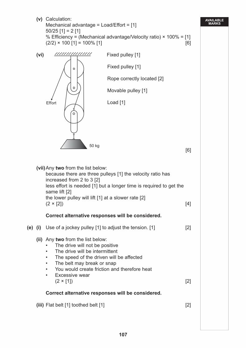
(v) Calculation: Mechanical advantage = Load/Effort = [1] 50/25 [1] = 2 [1] % Efficiency = (Mechanical advantage/Velocity ratio) × 100% = [1] (2/2) × 100 [1] = 100% [1] [6]
(vi) Fixed pulley [1]
Fixed pulley [1]
Rope correctly located [2]
Movable pulley [1]
Load [1]
[6]
(vii) Any two from the list below: because there are three pulleys [1] the velocity ratio has
increased from 2 to 3 [2] less effort is needed [1] but a longer time is required to get the
same lift [2] the lower pulley will lift [1] at a slower rate [2] (2 × [2]) [4]
Correct alternative responses will be considered.
(e) (i) Use of a jockey pulley [1] to adjust the tension. [1] [2]
(ii) Any two from the list below: • The drive will not be positive • The drive will be intermittent • The speed of the driven will be affected • The belt may break or snap • You would create friction and therefore heat • Excessive wear
(2 × [1]) [2]
Correct alternative responses will be considered.
(iii) Flat belt [1] toothed belt [1] [2]
AVAILABLE MARKS
108
2 (a) (i) Double acting cylinder [1]
(ii) F = P × A 300 = 0.6 × A [1] A = 300/0.6 [1] = 500mm2 [1] Piston Area = 500 + 100 = 600mm2 [2] [5]
(b) (i) A is push button operated [1] F is roller trip operated [1]
(ii) SAC has one port and one return Spring [1] DAC has two ports [1]
(iii) Signal to switch 5/2 valve B [1] cylinder outstrokes [1] outstrokes slowly because of one way flow restrictor [1] 3/2 roller valve F operated [1] C and D form a time delay [1] valve B reset cylinder instrokes [1] [6]
(iv) Adjust [1] or open the restrictor valve E [2] Change the position of valve F [1] or lower the position of
valve F [2] (2 × [2]) [4]
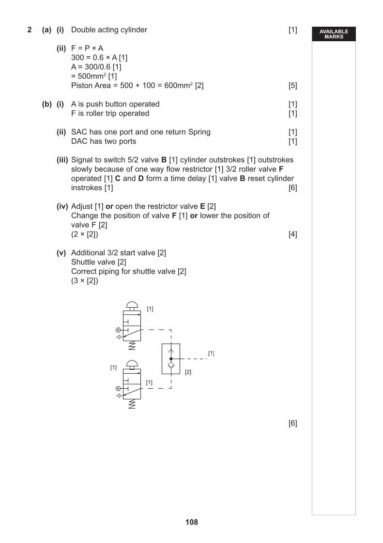
(v) Additional 3/2 start valve [2] Shuttle valve [2] Correct piping for shuttle valve [2] (3 × [2])
[6]

AVAILABLE MARKS
109
(c) (i)
Connection from start valve [1] to 5/2 valve at cylinder A [1] Signal from 3/2 roller valve at A+ [1] to 5/2 valve at cylinder B [1] Signal from 3/2 roller valve at B+ [1] to 5/2 valve at cylinder A [1] Signal from 3/2 roller valve at B+ [1] to 5/2 valve at cylinder B [1] (8 × [1]) [8]
(ii) Insert 3/2 roller valve [1] at B− [1] signal connected from 3/2 roller [1] to supply port of start valve [1] [4]
(d) Indicative Content:
Products: Example 1 train Example 2 pneumatic drills Example 3 bus
Function: Example 1 pneumatic door Example 2 bolts on a car wheel Example 3 the platform
Why it is used: Example 1 raise and lower for easy access to bus Example 2 automatic opening and closing of doors Example 3 tightening to the correct torque, or speed of operation, or
reduces effort for operator
Correct alternative responses will be considered.

AVAILABLE MARKS
110
Response Type Description Mark Band
When a response is not worthy of credit [0] should be awarded.
Limited
Student outlines at least one product that uses pneumatic systems and provides limited explanations of function and use.
The level of accuracy of spelling, punctuation and grammar is limited in most cases. Form and style is generally inappropriate as is the use of technical vocabulary and specialist terms.
[1]–[4]
Satisfactory
Student outlines at least two products that use pneumatic systems and provides satisfactory explanations of function and use.
The level of accuracy of spelling, punctuation and grammar is satisfactory in most cases. Form and style is generally appropriate as is the use of technical vocabulary and specialist terms.
[5]–[8]
Very good
Student outlines three products that use pneumatic systems and provides very good explanations of function and use.
The level of accuracy of spelling, punctuation and grammar is very good. Form and style is very good as is the use of technical vocabulary and specialist terms.
[9]–[12]
[12]
Total
50
100
MARKSCHEME
Technology and Design
[CODE]SPECIMEN
Unit 2
Option B: Mechanical and Pneumatic Control systems
Unit 2
Option C: Product Design
General Certificate of Secondary Education2019
111

AVAILABLE MARKS
112
1 (a) (i) BSI Kite Mark. [1]
(ii) Any two from the list below:• the product meets a given safety standard • the product has been independently tested• the manufacture has quality systems in place to ensure every
product meets the required standard (2 × [1]) [2]
Correct alternative responses will be considered.
(b) Any three from the list below: Identify the Hazard [1] Discuss the hazard [1]
• using the pillar drill without the guard in place• not wearing goggles when using the pillar drill • loose clothing or hair• allowing more than one person use the pillar drill at any one time • not having secured the material for drilling • not removing the chuck key after the drill bit has been inserted
(3 × [2]) [6]
Correct alternative responses will be considered.
2 (a) A Inception/Development B Introduction C Growth D Maturity E Decline (5 × [1]) [5]
(b) Want [1]
(c) Any four from the list below:• shrinking market• market saturation• consumers switching to new products• sales promotions• selling at discount stores• looking for new market opportunities• developing new products
(4 × [1]) [4]
Correct alternative responses will be considered.
9
10

AVAILABLE MARKS
113
3 (a) Any two from the list below:• welding • spray painting • pop Riveting • applying adhesive • assembly • quality checks
(2 × [1]) [2]
Correct alternative responses will be considered.
(b) Any three from the list below: Discussion which identifies the reason [1] The why [1]
• they increase the speed of production • reduce variations in labour costs • they reduce overall manufacturing costs • allows a company to become more competitive • increases the quality of products • enables a company to engage in continuous and mass
production • enables a company to compete on a global scale
(3 × [2]) [6]
Correct alternative responses will be considered.
(c) Any two from the list below:• very expensive initial cost of purchasing specialist robots and
software• cost of training staff to program and maintain the robots• down time due to reorganisation of the production system• replacing jobs with robots can result in job losses
(1 × [2]) [2]
Correct alternative responses will be considered.
4 (a) (i) Function follows Form [1]
(ii) Any two from the list below:• It would appear that the watering can’s aesthetics are the
primary driver• the product does not appear to be suitable for functional use • it is an expensive solution • it has no handle to assist with the use of the product• but the watering can is a creative and unique design • it is a limited addition piece
(2 × [1]) [2]
Correct alternative responses will be considered.
10
AVAILABLE MARKS
114
(b) Any one from the list below: • the watering can is a unique design • it is made of an expensive metal • it is an exhibition piece• function is not the primary driver [1]
Correct alternative responses will be considered.
(c) Any five from the list below:• multidisciplinary – furniture, lighting and products• designed the London 2012 Olympic Torch• developed work for other well-known brands including Sony,
Louis Vitton, Swarovski and the Royal Mint• work is on display in museums in London and New York• winners of numerous design awards• they work across a variety of mediums
(5 × [1]) [5]
Correct alternative responses will be considered.
5 (a) Calculation: • 4 tables per sheet [1]• Cost of Pine £15/Cost of Chipboard Oak Veneer £8 [1]• £7.50 saving per table [1]
Or
• £60 - £30 = £30 [1]• £30 / 4 [1]• £7.50 [1]
(3 × [1]) [3]
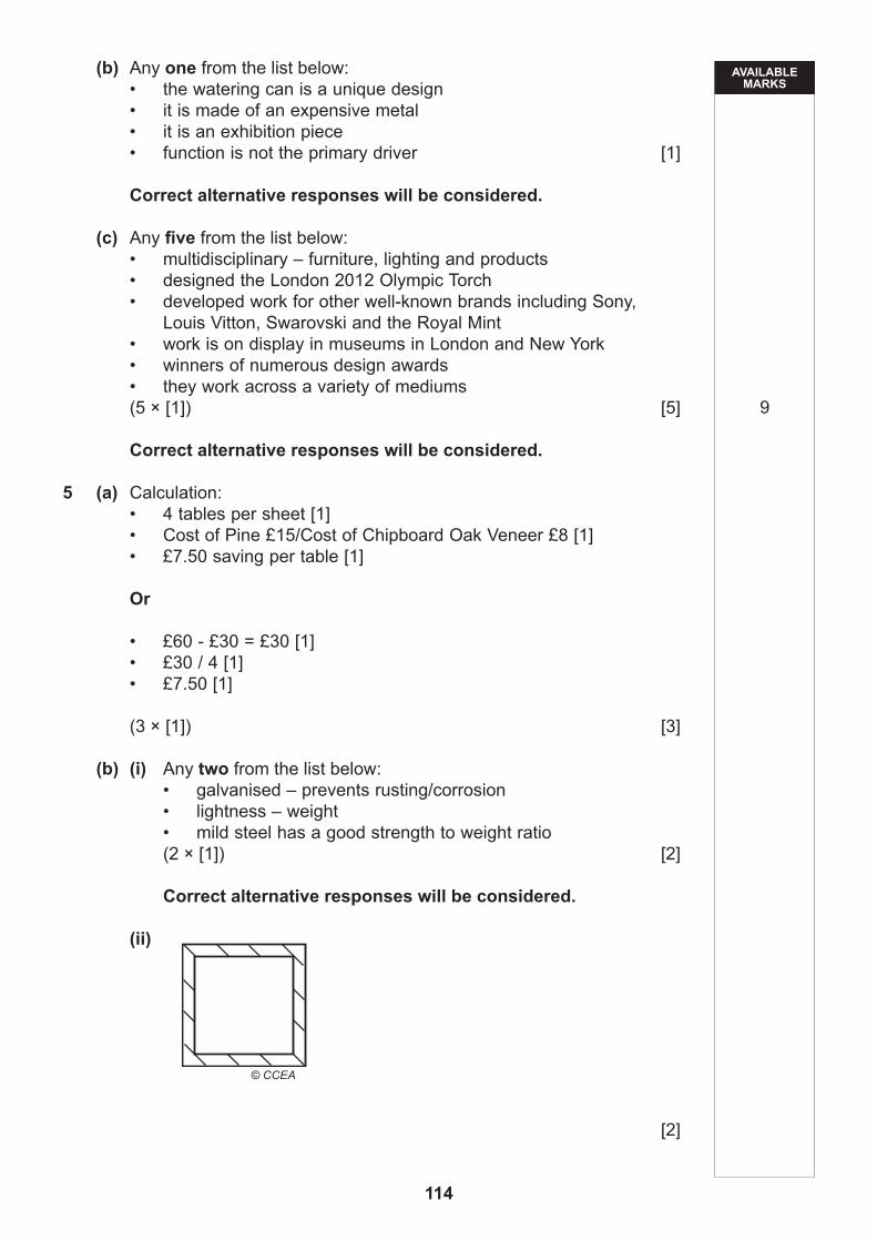
(b) (i) Any two from the list below: • galvanised – prevents rusting/corrosion• lightness – weight• mild steel has a good strength to weight ratio
(2 × [1]) [2]
Correct alternative responses will be considered.
(ii)
[2]
9
© CCEA

AVAILABLE MARKS
115
(iii) Calculation:• 20 × 20 = 400 [1]• 16 × 16 = 256 [1]• 400 – 256 = 144 mmsq [1] or• Ans = 144 mmsq [3]
Or
• 20 × 2 × 2 = 80 [1]• 16 × 2 × 2 = 64 [1]• 80 + 64 = 144 [1] or• Ans = 144 mmsq [3] [3]
(c) Sketch, design and construction
Response Type Description Mark Band
When a response is not worthy of credit [0] should be awarded.
Limited
Student produces sketches which do not convey a clear solution and show limited ideas. The construction lacks detail.
The level of annotation conveys limited information and lacks technical vocabulary and specialist terms.
[1]–[3]
Satisfactory
Student produces satisfactory sketches which convey some ideas of the solution. The construction details are generally satisfactory.
The level of annotation is satisfactory and contains some technical vocabulary and specialist terms.
[4]–[7]
Very good
Student produces very good sketches which clearly convey most or all of the design solution. The construction details are detailed.
The level of annotation and technical vocabulary and specialist terms is generally very good.
[8]–[10]
[10] 20

AVAILABLE MARKS
116
6 (a) Calculation:• 6.50 – 0.35 = 6.15 [1]• 6.15 × 35 = £215.25 [1] or• Ans = £215.25 [2]
Or
• (6.50 × 35 = £227.50) – (0.35 × 35 = £12.25) [1]• 227.50 – 12.25 = £215.25 [1] or• Ans = £215.25 [2]
(1 × [2]) [2]
(b) Any three from the list below:• standard of living is different between the two countries • difference in the availability of or lack of labour • availability of raw materials • moral issues associated with the protection of workers • working conditions are different between the two countries • government policies and taxes for each country are different • welfare or lack of welfare of employees
(3 × [2]) [6]
Correct alternative responses will be considered.
(c) (i) China [1] (ii) 3 countries [1] (iii) 80 [1] million [1] [2]
7 (a) Any one from both of the lists below:
Function:• the modern television in Fig. 7 can be controlled with a remote
control [1] This enables the user to operate the television from a distance or from the comfort of a chair [1]
• the modern television in Fig. 7 can be wall mounted or placed on a stand [1] This offers greater flexibility for location [1] It requires less space in a room [1] it allows a greater number to view the television [1]
Aesthetics:• the modern television in Fig. 7 has a slim line screen [1] Because
of this the modern television takes up less space in a room [1]• the modern television in Fig. 7 has a smaller frame around the
screen [1] for a given size the screen is bigger [1] the frame around the screen is less intrusive [1]
(2 × [2]) [4]
Correct alternative responses will be considered.
12

AVAILABLE MARKS
117
(b) Any two from the list below: • Internet • Games • DVD • Phone • HD • Skype • Stereo Sound • Large number of channels • Freeview • Pre-record • Playback • Pixel quality • Rewind live TV
(2 × [1]) [2]
Correct alternative responses will be considered.
(c) (i) Anthropometric data involves statistics on human dimensions. [1]
(ii) Any three from the list below:• size of the buttons• distances between controller buttons• height, length, width of the controller• key functions
(3 × [1]) [3]
Correct alternative responses will be considered.
8 The design solution must show evidence of the following features: • good quality annotated sketches giving consideration to line, shape,
form and proportion. The annotated sketches should clearly convey the candidates thinking.
• hold up to 100 A4 sheets of paper which measure 300 mm × 210 mm × 25 mm and hold the following other small stationery items 4 pens, 2 pencils, one pack of Post-it notes and one 300 mm ruler
• be free standing and able to sit on the desk• identify and justify the choice and use of materials• identify and justify the main manufacturing techniques used in the
design’s construction• be aesthetically pleasing and suitable for teenagers• include three key dimensions
Quality of written communication is assessed in this question.
10

AVAILABLE MARKS
118
Response Type Description Mark Band
When a response is not worthy of credit [0] should be awarded.
Limited
Student makes an attempt to include some or all of the features listed.
Student produces sketches which do not convey a clear solution and show limited ideas. The level of annotation conveys limited information and lacks technical vocabulary and specialist terms.
The accuracy of spelling, punctuation and grammar is limited.
[1]–[7]
Satisfactory
Student makes an attempt to include some or all of the features listed.
Student produces satisfactory sketches which convey some ideas of the solution. The level of annotation is satisfactory and contains some technical vocabulary and specialist terms.
The accuracy of spelling, punctuation and grammar is satisfactory.
[8]–[14]
Very good
Student makes an attempt to include most or all of the features listed.
Student produces very good sketches which clearly convey most or all of the design solution. The level of annotation and technical vocabulary and specialist terms is generally very good.
The accuracy of spelling, punctuation and grammar is very good.
[15]–[20]
[20]
Total
20
100


© CCEA 2017