Embed Size (px)
Citation preview
The business of sustainability
CCR Unit Closure and Post-Closure Plan
Texas Municipal Power Agency Gibbons Creek Steam Electric Station Grimes County, Texas
October 12, 2016
www.erm.com
Texas Registered Engineering Firm F-2393 Texas Board of Professional Geoscientist Firm 50036
Texas Municipal Power Agency
CCR Unit Closure and Post-Closure Plan: Gibbons Creek Steam Electric Station
October 12, 2016
Project No. 0336706 Grimes County, Texas
James Davidson Partner-in-Charge
Kenneth R. Schroeder, P.E. Project Director
Charles O. Johnson Project Manager
E. Doyon Main, P.E. Project Engineer Environmental Resources Management 206 East 9th Street, Suite 1700 Austin, Texas 78701 T: 512-459-4700 F: 512-597-8365
0336706/A8259 Closure-Post Closure Plan.docx iii
TABLE OF CONTENTS
1.0 INTRODUCTION 1
1.1 REQUIREMENTS 1 1.2 DEFINITIONS 1
2.0 CCR UNIT DESCRIPTION 3
2.1 ASH PONDS 3 2.2 SCRUBBER SLUDGE POND 4 2.3 SITE F LANDFILL 5
3.0 CCR UNIT CLOSURE PLAN 6
3.1 CLOSURE PERFORMANCE STANDARDS 6 3.1.1 Closure In Place 6
3.2 NARRATIVE DESCRIPTION OF THE CLOSURE 7 3.2.1 Description of Closure In Place 7
3.3 FINAL COVER SYSTEM 7 3.3.1 Final Cover System Design Criteria 8
3.4 ALTERNATIVE FINAL COVER SYSTEM DESIGN CRITERIA 8 3.4.1 Methods and Procedures Used to Install the Final Cover
System 9 3.5 CCR VOLUME ESTIMATE 11 3.6 FINAL COVER AREA 11 3.7 CLOSURE SCHEDULE 11
4.0 CCR UNIT POST-CLOSURE CARE 13
4.1 POST-CLOSURE PERIOD 13 4.2 POST CLOSURE INSPECTION AND MAINTENANCE 14 4.3 CONTACT INFORMATION 14 4.4 PLANNED CCR UNIT POST-CLOSURE PROPERTY USE 15
5.0 CCR UNIT CLOSURE AND POST-CLOSURE PLAN AMENDMENT 16
6.0 NOTIFICATION AND RECORD KEEPING 17
6.1 NOTIFICATIONS 17 6.2 TMPA CCR INTERNET SITE 17 6.3 DEED NOTATION 18
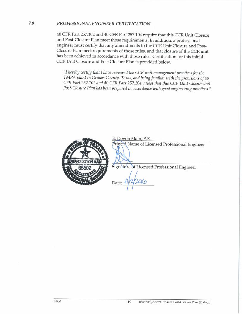
7.0 PROFESSIONAL ENGINEER CERTIFICATION 19
0336706/A8259 Closure-Post Closure Plan.docx iv
List of Tables
Table 1 Estimated Closure Schedule – Ash Ponds and Scrubber Sludge Pond
Table 2 Estimated Closure Schedule – Site F Landfill
List of Figures
Figure 1 Site Base Map
Figure 2 Cap Concept Grading Plan – Ash Ponds
Figure 3 Cap Concept Grading Plan – Scrubber Sludge Pond
Figure 4 Cap Concept Grading Plan – Site F Landfill
ERM 0336706\A8259 Closure-Post Closure Plan.docx 1
1.0 INTRODUCTION The Texas Municipal Power Agency (TMPA) owns and operates the Gibbons Creek Steam Electric Station (GCSES) facility located in unincorporated Grimes County, Texas. The GCSES generates coal combustion residuals (CCR) that are regulated under Title 40, Code of Federal Regulations, Part 257 (40 CFR Part 257)(CCR Rule). This document is the Closure Plan and Post-Closure Plan (CPC Plan) for two CCR surface impoundments and one CCR landfill at the GCSES:
(1) the Ash Ponds (APs),
(2) the Scrubber Sludge Pond (SSP), and
(3) the Site F Landfill (SFL). This CPC Plan describes the steps necessary to close the CCR units at any point during the active life of the CCR unit with CCR left in place in accordance with 40 CFR §257.102(b). This CPC Plan also describes post-closure inspection, maintenance and monitoring required for the CCR unit closed with CCR left in place in accordance with 40 CFR Part 257.102(b). According to 40 CFR 257.102 (b)(3)(i), TMPA may amend this initial or any subsequent written closure plan at any time. Per 40 CFR 257.102 (b)(3)(ii), TMPA must amend the closure plan whenever:
(A) there is a change in operation of the CCR unit that would substantially affect the written closure plan in effect; or
(B) before or after closure activities have commenced, unanticipated events necessitate a revision of the written closure plan.
1.1 REQUIREMENTS
Regulations in 40 CFR §257.102 et seq. require the preparation, certification, posting on an internet site accessible by the public, and, on closure, implementation of a Closure Plan and Post-Closure Plan for each existing active CCR unit. A completed, certified copy of this Plan must be placed maintained indefinitely in the TMPA Operating Record by October 17. TMPA will issue notifications and implement recordkeeping in accordance with 40 CFR §257.105 and 40 CFR §257.106 (see section 6).
1.2 DEFINITIONS This CPC Plan includes terms defined consistent with parts of 40 CFR §257.53 (re: 80 FR 21468, April 17, 2015; 80 FR 37988, July 2, 2015). and associated editions of the Federal Register as noted below.
ERM 0336706\A8259 Closure-Post Closure Plan.docx 2
Active life or in operation means the period of operation beginning with the initial placement of CCR in the CCR unit and ending at completion of closure activities in accordance with 40 CFR §257.102.
Closed means placement of CCR in a CCR unit has ceased, and the owner or operator has completed closure of the CCR unit in accordance with 40 CFR §257.102 and has initiated post-closure care in accordance with §257.104.
Coal combustion residuals (CCR) means fly ash, bottom ash, boiler slag and flue gas desulfurization materials generated from burning coal for the purpose of generating electricity by electric utilities and independent power producers
CCR landfill means an area of land or an excavation that receives CCR and which is not a surface impoundment, an underground injection well, a salt dome formation, a salt bed formation, an underground or surface coal mine, or a cave. For purposes of the CCR Rule, a CCR landfill also includes sand and gravel pits and quarries that receive CCR, CCR piles, and any practice that does not meet the definition of a beneficial use of CCR
CCR surface impoundment means a natural topographic depression, manmade excavation, or diked area, which is designed to hold an accumulation of CCR and liquids, and the unit treats, stores, or disposes of CCR.
CCR unit means any CCR landfill, CCR surface impoundment, or lateral expansion of a CCR unit, or a combination of more than one of these units, based on the context of the paragraph(s) in which it is used. This term includes both new and existing units, unless otherwise specified.
Facility means all contiguous land, and structures, other appurtenances, and improvements on the land, used for treating, storing, disposing, or otherwise conducting solid waste management of CCR. A facility may consist of several treatment, storage, or disposal operational units (e.g. one or more landfills, surface impoundments, or combinations of them).
Qualified professional engineer means an individual who is licensed by a state as a Professional Engineer to practice one or more disciplines of engineering and who is qualified by education, technical knowledge and experience to make the specific technical certifications required under this subpart. Professional engineers making these certifications must be currently licensed in the state where the CCR unit(s) is located.
ERM 0336706\A8259 Closure-Post Closure Plan.docx 3
2.0 CCR UNIT DESCRIPTION The TMPA GCSES is a coal fired steam electric plant capable of generating approximately 470 MW. Construction of the GCSES began in 1977. The GCSES began generating electric power in 1982. TMPA currently operates three CCR units at the GCSES which are subject to requirements in 40 CFR §257:
the Ash Ponds (APs),
the Scrubber Sludge Pond (SSP), and
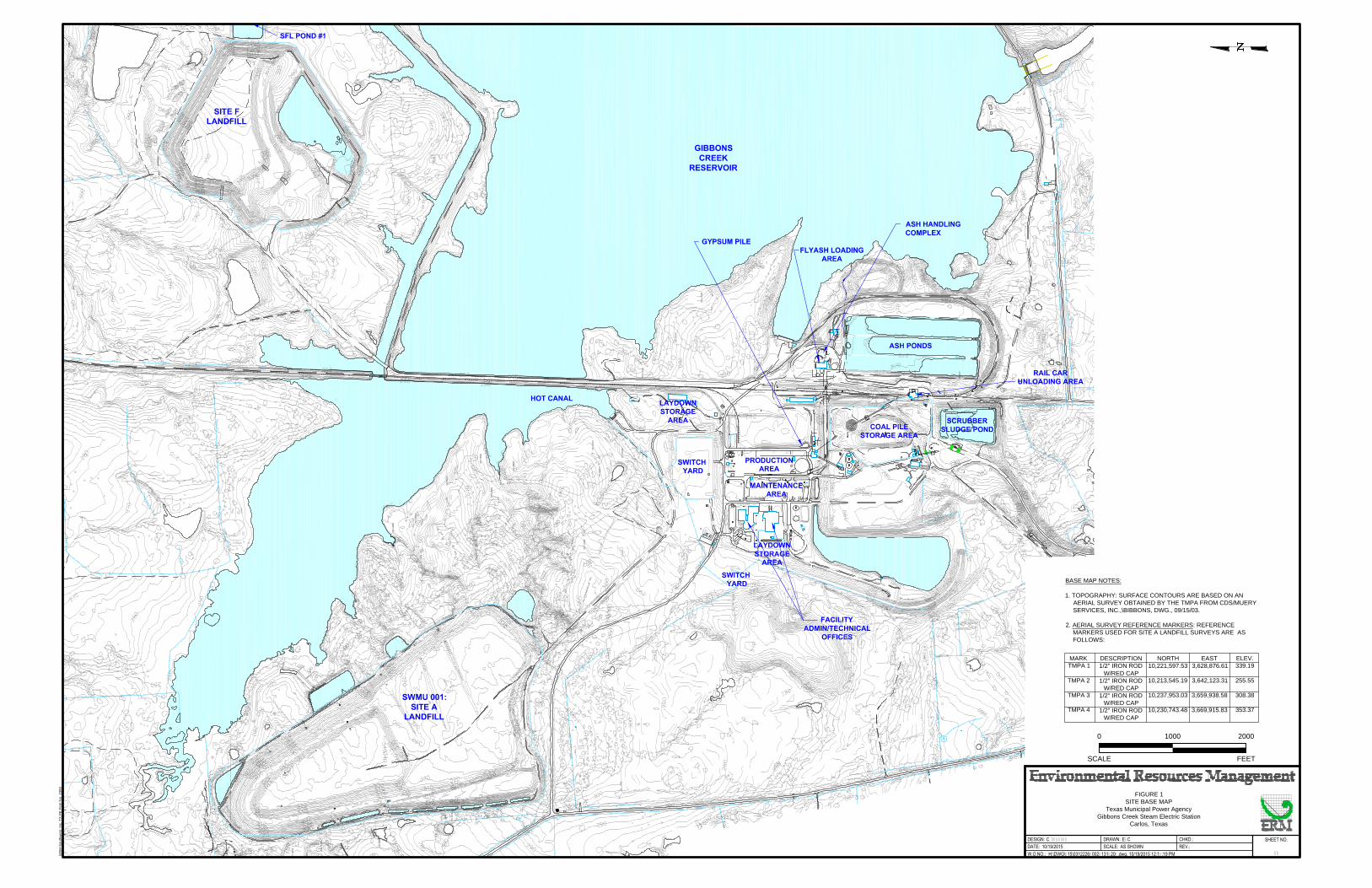
the Site F Landfill (SFL). The location of each of those CCR unit is shown on Figure 1. The CCR units are described below.
2.1 ASH PONDS The APs are three adjoining and connected CCR surface impoundments constructed by TMPA between 1977 and 1978 as part of the original GCSES plant construction. The APs are a surface impoundment that was constructed and received CCR before October 14, 2015. In addition, the APs currently receive CCR. Hence, in accordance with 40 CFR §257.53, the APs are classified as an active existing CCR surface impoundment. In addition, the APs are listed as Solid Waste Management Unit (SWMU) 006 on the Notice of Registration (NOR) for Solid Waste Registration (SWR) 32271 issued to TMPA by the TCEQ. The NOR states that the APs are an active surface impoundment. As shown on the NOR and the TMPA water balance, TMPA Dwg. No. 10-C-301, dated February 17, 2016, the APs receive and store bottom ash transport water overflow from hydrobins used to dewater the bottom ash CCR produced by the GCSES. Those wastes contain CCR as defined in 40 CFR §257.52. The APs are located on the GCSES site generally southeast of the GCSES electric power generation plant and west of Gibbons Creek Reservoir; see Figure 1. As shown on TMPA Dwg. No. C-230-003, dated October 28, 1977, each of the three APs is approximately 1820 feet long and 245 feet wide at the dike crest interior top of bank, and 20 feet deep from the dike crest to the pond bottom. Based on those dimensions, the total area inside the interior top of bank of the three APs is approximately 30.7 acres. Similarly, the total area drained to the APs, including the interior and the dike crest area, is approximately 34.8 acres.
ERM 0336706\A8259 Closure-Post Closure Plan.docx 4
According to TMPA personnel, the estimated maximum total volume of CCR ever on-site over the active life of the APs is estimated to be 360,000 cubic yards, estimated by 50% of the available storage capacity of the APs. The largest area for the APs final cover is estimated to be approximately 30.7 acres.
2.2 SCRUBBER SLUDGE POND The SSP is a CCR surface impoundment constructed by TMPA between 1977 and 1978 as part of the original GCSES plant construction. The SSP is a surface impoundment that was constructed and received CCR before October 14, 2015. In addition, the SSP currently receives CCR. Hence, in accordance with 40 CFR §257.53, the SSP is classified as an active existing CCR surface impoundment. In addition, the SSP is listed as SWMU 004 on the NOR for SWR 32271 issued to TMPA by the TCEQ. The NOR states that the SSP is an active surface impoundment. As shown on the NOR and the TMPA water balance, TMPA Dwg. No. 10-C-301, dated February 17, 2016,, the SSP receives process water from the Scrubber Purge Treatment system. That waste contains CCR as defined in 40 CFR §257.52. Also as shown on the TMPA water balance, TMPA pumps water from the SSP to the APs at times and rates determined by TMPA to be necessary and appropriate to maintain adequate freeboard in the SSP. The SSP is located on the GCSES site generally south of the plant and west of the APs; see Figure 1. As shown on TMPA Dwg. No. 11-C-019.1, dated February 15, 2000, the SSP is approximately 750 feet long, 380 feet wide on the northern side, 470 feet wide on the southern side at the dike crest interior top of bank, and 20 feet deep from the dike crest to the pond bottom. Based on those dimensions, the total area inside the SSP is approximately 7.3 acres. Similarly, the total area drained to the SSP, including the interior and the dike crest areas, is approximately 7.9 acres. According to TMPA personnel, the maximum volume of CCR ever on-site over the active life of the SSP is estimated to be 95,000 cubic yards, estimated by 50% of the available storage capacity of the SSP. The largest area of the SSP final cover is estimated to be approximately 7.3 acres.
ERM 0336706\A8259 Closure-Post Closure Plan.docx 5
2.3 SITE F LANDFILL The SFL is a CCR landfill constructed by TMPA in 1990 and expanded in 1995 to increase the onsite disposal capacity for CCR solid wastes generated by the GCSES. The SFL is a landfill that was constructed and received CCR before October 14, 2015. In addition, the SFL currently receives CCR. Hence, in accordance with 40 CFR §257.53, the SFL is classified as an active existing CCR landfill. In addition, the SFL is listed as SWMU 001 on the NOR for SWR 32271 issued to TMPA by the TCEQ. The NOR states that the SFL is an active SWMU. The NOR states that the SFL receives CCR wastes consisting of fly ash, fly ash mixed with dewatered scrubber sludge, dewatered scrubber sludge, and bottom ash generated by the GCSES plant. Those wastes are defined as CCR in 40 CFR §257.52. The SFL is located generally northeast of the GCSES plant and north of the Gibbons Creek Reservoir; see Figure 1. The total area covered by the SFL inside the perimeter dike interior top of bank, is approximately 95 acres. According to TMPA personnel, the maximum volume of CCR ever on-site over the active life of the SFL is estimated to be [TMPA ESTIMATE] cubic yards. The largest area of the SFL final cover is approximately 95 acres.
ERM 0336706\A8259 Closure-Post Closure Plan.docx 6
3.0 CCR UNIT CLOSURE PLAN The closure concept for this initial closure plan is to close a CCR unit by leaving CCR in place, The closure procedures will comply with requirements in 40 CFR §257.102(d). This section describes the steps necessary to close the CCR unit at any point during the active life of the CCR unit consistent with recognized and generally accepted good engineering practices and in accordance with 40 CFR §257.102(b), including: A written closure plan for each CCR unit is required by 40 CFR 256.102(b). Each closure plan is required to include:
the closure performance standard;
a narrative description of the closure;
a description of the final cover system;
the maximum CCR inventory;
the maximum area covered; and
the closure schedule. The CCR unit closure plan is described in this section.
3.1 CLOSURE PERFORMANCE STANDARDS The performance standards for closure of the CCR units in this initial closure plan is leaving CCR in place in accordance with 40 CFR §257.102(d)(closure in place).
3.1.1 Closure In Place TMPA may close any of the CCR units by leaving CCR in place and constructing a final cover system in accordance with the performance standards stated in 40 CFR §257.102(d)(1):
(i) Control, minimize or eliminate, to the maximum extent feasible, post-closure infiltration of liquids into the waste and releases of CCR, leachate, or contaminated run-off to the ground or surface waters or to the atmosphere;
(ii) Preclude the probability of future impoundment of water, sediment, or slurry;
(iii) Include measures that provide for major slope stability to prevent the sloughing or movement of the final cover system during the closure and post-closure care period;
(iv) Minimize the need for further maintenance of the CCR unit; and
(v) Be completed in the shortest amount of time consistent with recognized and generally accepted good engineering practices.
In addition, requirements for closure of the CCR unit using TRRP Remedy Standard B in accordance with 30 TAC §350 will also apply to closure of a CCR unit by leaving CCR in place.
ERM 0336706\A8259 Closure-Post Closure Plan.docx 7
3.2 NARRATIVE DESCRIPTION OF THE CLOSURE
Closure of a CCR will be accomplished in steps related to the closure performance standard, the type of CCR unit (i.e. CCR landfill or CCR surface impoundment), and the characteristics of the bottom liner, the CCR contained in the CCR unit, and the surrounding area. In addition, requirements for closure of the CCR unit using TRRP Remedy Remedy Standard B for closure in place in accordance with 30 TAC §350 will also be implemented for the closure chosen by TMPA.
3.2.1 Description of Closure In Place CCR units at the GCSES will be closed by leaving CCR in place (closure in place), the closure will be accomplished in steps as follows.
1. TRRP Planning Deliverables: TMPA will prepare, submit to the TCEQ, and obtain TCEQ approval of an Affected Property Assessment Report (APAR) and Response Action Plan (RAP) for closure of the CCR unit in accordance with Remedy Standard B and related rules in 30 TAC §350.
2. Remove Liquids: Free liquids will be eliminated by removing liquid wastes and/or solidifying the remaining CCR and CCR residues in the CCR unit.
3. Prepare Final Cover System Subgrade: If the CCR unit is a CCR landfill the interim cover surface will be stripped of vegetation, if necessary, and the surface will be graded and compacted as necessary to support the final cover system. If the CCR unit is a surface impoundment, remaining CCR will be solidified, if necessary, sufficient to support the final cover system, and the surface will be graded and compacted as necessary to support the final cover system.
4. Final Cover System: The final cover system will be constructed in place over the prepared subgrade to achieve the final cover system criteria in 40 CFR §257.102(d)(3).
5. TRRP Completion Report: TMPA will prepare, submit to the TCEQ, and obtain TCEQ approval of a Response Action Completion Report for closure of the CCR unit in accordance with the RAP approved by the TCEQ and related rules in 30 TAC §350.
3.3 FINAL COVER SYSTEM
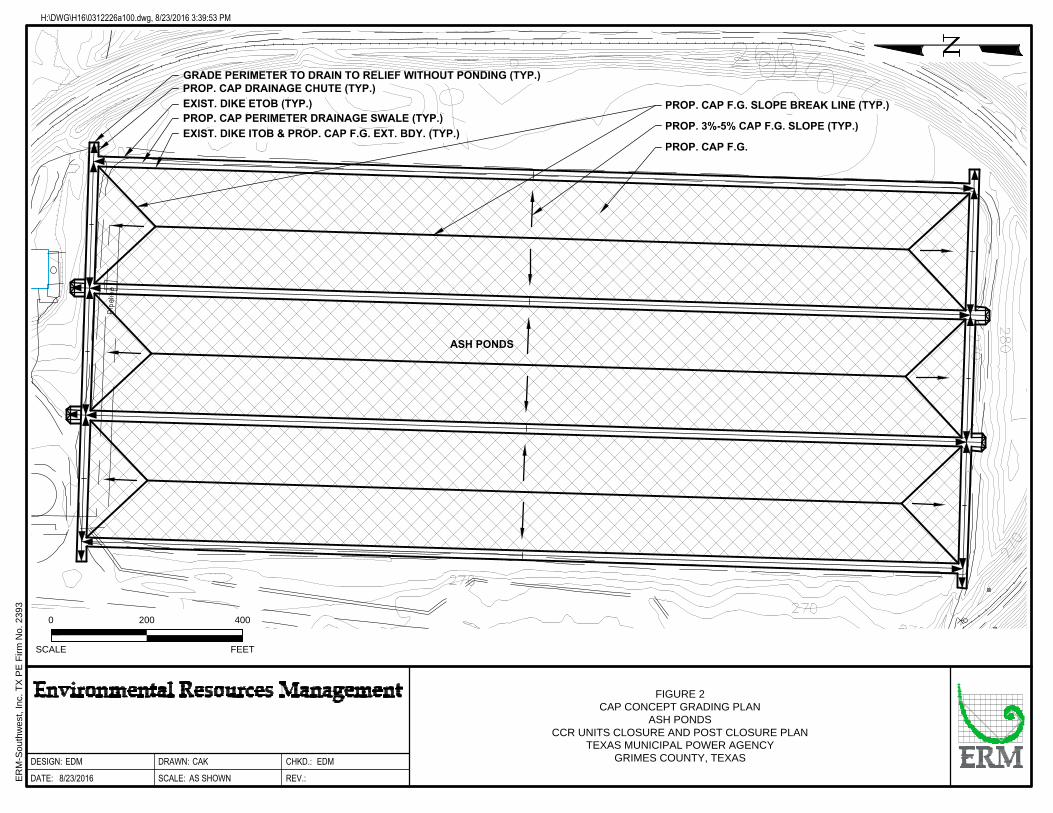
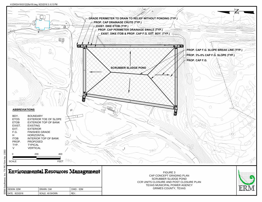
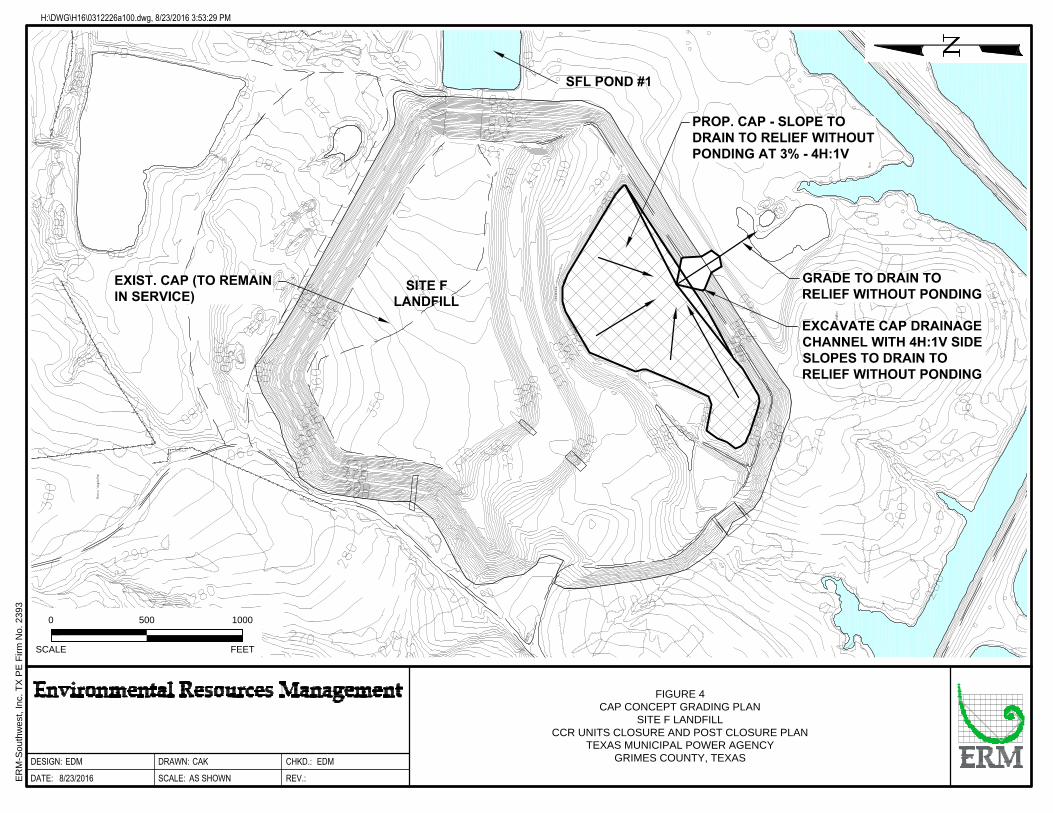
The final cover system will be as described below. Additional requirements in a RAP prepared by TMPA for closure of that CCR unit and approved by the TCEQ in accordance with rules in 30 TAC §350 will also be implemented. Conceptual representations of the APs, SSP, and SFL grading plans are presented in Figures 2 through 4.
ERM 0336706\A8259 Closure-Post Closure Plan.docx 8
3.3.1 Final Cover System Design Criteria The final cover system constructed for closure of the CCR unit will achieve the final cover system design criteria specified in 40 CFR 102(d)(3)(i):
(A) The permeability of the final cover system must be less than or equal to the permeability of any bottom liner system or natural subsoils present, or a permeability no greater than 1 × 10⁻⁵ cm/sec, whichever is less.
(B) The infiltration of liquids through the closed CCR unit must be minimized by the use of an infiltration layer that contains a minimum of 18 inches of earthen material.
(C) The erosion of the final cover system must be minimized by the use of an erosion layer that contains a minimum of six inches of earthen material that is capable of sustaining native plant growth.
(D) The disruption of the integrity of the final cover system must be minimized through a design that accommodates settling and subsidence.
Additional final cover system design criteria specified in a RAP prepared by TMPA for closure of that CCR unit and approved by the TCEQ in accordance with rules in 30 TAC §350 will also apply.
3.4 ALTERNATIVE FINAL COVER SYSTEM DESIGN CRITERIA
IF TMPA chooses to construct an alternative final cover system for closure of the CCR unit, the final cover system will achieve the alternative final cover system design criteria specified in 40 CFR §257.102(d)(3)(ii):
(A) The design of the final cover system must include an infiltration layer that achieves an equivalent reduction in infiltration as the infiltration layer specified in [40 CFR §257.102](d)(3)(i)(A) and (B) [i.e. the permeability of the final cover system must be less than or equal to the permeability of any bottom liner system or natural subsoils present, or a permeability no greater than 1 × 10⁻⁵ cm/sec, whichever is less; and the infiltration of liquids through the closed CCR unit must be minimized by the use of an infiltration layer that contains a minimum of 18 inches of earthen material].
(B) The design of the final cover system must include an erosion layer that provides equivalent protection from wind or water erosion as the erosion layer specified in [40 CFR §257.102](d)(3)(i)(C) [i.e. the erosion of the final cover system must be minimized by the use of an erosion layer that contains a minimum of six inches of earthen material that is capable of sustaining native plant growth].
(C) The disruption of the integrity of the final cover system must be minimized through a design that accommodates settling and subsidence.
Additional final cover system design criteria specified in a RAP prepared by TMPA for closure of that CCR unit and approved by the TCEQ in accordance with rules in 30 TAC §350 will also apply.
ERM 0336706\A8259 Closure-Post Closure Plan.docx 9
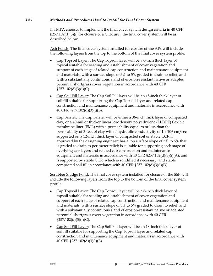
3.4.1 Methods and Procedures Used to Install the Final Cover System If TMPA chooses to implement the final cover system design criteria in 40 CFR §257.102(d)(3)(i) for closure of a CCR unit, the final cover system will be as described below. Ash Ponds: The final cover system installed for closure of the APs will include the following layers from the top to the bottom of the final cover system profile.
Cap Topsoil Layer: The Cap Topsoil layer will be a 6-inch thick layer of topsoil suitable for seeding and establishment of cover vegetation and support of each stage of related cap construction and maintenance equipment and materials, with a surface slope of 3% to 5% graded to drain to relief, and with a substantially continuous stand of erosion-resistant native or adapted perennial shortgrass cover vegetation in accordance with 40 CFR §257.102(d)(3)(i)(C).
Cap Soil Fill Layer: The Cap Soil Fill layer will be an 18-inch thick layer of soil fill suitable for supporting the Cap Topsoil layer and related cap construction and maintenance equipment and materials in accordance with 40 CFR §257.102(d)(3)(i)(B).
Cap Barrier: The Cap Barrier will be either a 36-inch thick layer of compacted clay, or a 40-mil or thicker linear low density polyethylene (LLDPE) flexible membrane liner (FML) with a permeability equal to or less than the permeability of 3-feet of clay with a hydraulic conductivity of 1 x 10⁻⁷ cm/sec supported on a 12-inch thick layer of compacted soil or stable CCR if approved by the designing engineer; has a top surface slope of 3% to 5% that is graded to drain to perimeter relief; is suitable for supporting each stage of overlying cap layers and related cap construction and maintenance equipment and materials in accordance with 40 CFR §257.102(d)(3)(i)(A); and is supported by stable CCR, which is solidified if necessary, and stable compacted soil fill in accordance with 40 CFR §257.102(d)(3)(i)(D).
Scrubber Sludge Pond: The final cover system installed for closure of the SSP will include the following layers from the top to the bottom of the final cover system profile.
Cap Topsoil Layer: The Cap Topsoil layer will be a 6-inch thick layer of topsoil suitable for seeding and establishment of cover vegetation and support of each stage of related cap construction and maintenance equipment and materials, with a surface slope of 3% to 5% graded to drain to relief, and with a substantially continuous stand of erosion-resistant native or adapted perennial shortgrass cover vegetation in accordance with 40 CFR §257.102(d)(3)(i)(C).
Cap Soil Fill Layer: The Cap Soil Fill layer will be an 18-inch thick layer of soil fill suitable for supporting the Cap Topsoil layer and related cap construction and maintenance equipment and materials in accordance with 40 CFR §257.102(d)(3)(i)(B).
ERM 0336706\A8259 Closure-Post Closure Plan.docx 10
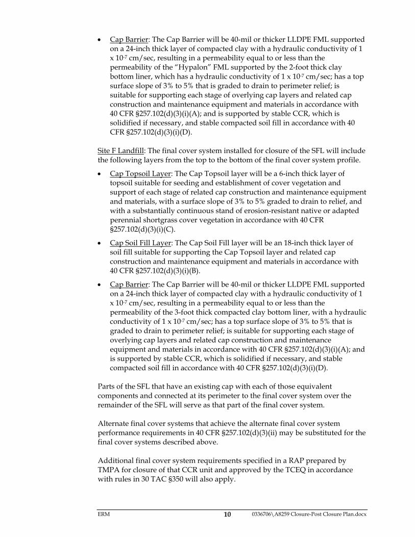
Cap Barrier: The Cap Barrier will be 40-mil or thicker LLDPE FML supported on a 24-inch thick layer of compacted clay with a hydraulic conductivity of 1 x 10⁻⁷ cm/sec, resulting in a permeability equal to or less than the permeability of the “Hypalon” FML supported by the 2-foot thick clay bottom liner, which has a hydraulic conductivity of 1 x 10⁻⁷ cm/sec; has a top surface slope of 3% to 5% that is graded to drain to perimeter relief; is suitable for supporting each stage of overlying cap layers and related cap construction and maintenance equipment and materials in accordance with 40 CFR §257.102(d)(3)(i)(A); and is supported by stable CCR, which is solidified if necessary, and stable compacted soil fill in accordance with 40 CFR §257.102(d)(3)(i)(D).
Site F Landfill: The final cover system installed for closure of the SFL will include the following layers from the top to the bottom of the final cover system profile.
Cap Topsoil Layer: The Cap Topsoil layer will be a 6-inch thick layer of topsoil suitable for seeding and establishment of cover vegetation and support of each stage of related cap construction and maintenance equipment and materials, with a surface slope of 3% to 5% graded to drain to relief, and with a substantially continuous stand of erosion-resistant native or adapted perennial shortgrass cover vegetation in accordance with 40 CFR §257.102(d)(3)(i)(C).
Cap Soil Fill Layer: The Cap Soil Fill layer will be an 18-inch thick layer of soil fill suitable for supporting the Cap Topsoil layer and related cap construction and maintenance equipment and materials in accordance with 40 CFR §257.102(d)(3)(i)(B).
Cap Barrier: The Cap Barrier will be 40-mil or thicker LLDPE FML supported on a 24-inch thick layer of compacted clay with a hydraulic conductivity of 1 x 10⁻⁷ cm/sec, resulting in a permeability equal to or less than the permeability of the 3-foot thick compacted clay bottom liner, with a hydraulic conductivity of 1 x 10⁻⁷ cm/sec; has a top surface slope of 3% to 5% that is graded to drain to perimeter relief; is suitable for supporting each stage of overlying cap layers and related cap construction and maintenance equipment and materials in accordance with 40 CFR §257.102(d)(3)(i)(A); and is supported by stable CCR, which is solidified if necessary, and stable compacted soil fill in accordance with 40 CFR §257.102(d)(3)(i)(D).
Parts of the SFL that have an existing cap with each of those equivalent components and connected at its perimeter to the final cover system over the remainder of the SFL will serve as that part of the final cover system. Alternate final cover systems that achieve the alternate final cover system performance requirements in 40 CFR §257.102(d)(3)(ii) may be substituted for the final cover systems described above. Additional final cover system requirements specified in a RAP prepared by TMPA for closure of that CCR unit and approved by the TCEQ in accordance with rules in 30 TAC §350 will also apply.
ERM 0336706\A8259 Closure-Post Closure Plan.docx 11
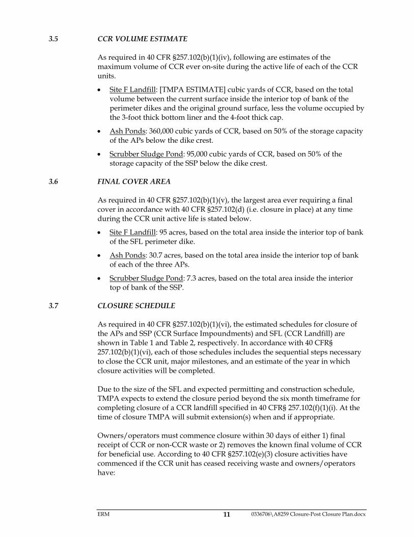
3.5 CCR VOLUME ESTIMATE As required in 40 CFR §257.102(b)(1)(iv), following are estimates of the maximum volume of CCR ever on-site during the active life of each of the CCR units.
Site F Landfill: [TMPA ESTIMATE] cubic yards of CCR, based on the total volume between the current surface inside the interior top of bank of the perimeter dikes and the original ground surface, less the volume occupied by the 3-foot thick bottom liner and the 4-foot thick cap.
Ash Ponds: 360,000 cubic yards of CCR, based on 50% of the storage capacity of the APs below the dike crest.
Scrubber Sludge Pond: 95,000 cubic yards of CCR, based on 50% of the storage capacity of the SSP below the dike crest.
3.6 FINAL COVER AREA
As required in 40 CFR §257.102(b)(1)(v), the largest area ever requiring a final cover in accordance with 40 CFR §257.102(d) (i.e. closure in place) at any time during the CCR unit active life is stated below.
Site F Landfill: 95 acres, based on the total area inside the interior top of bank of the SFL perimeter dike.
Ash Ponds: 30.7 acres, based on the total area inside the interior top of bank of each of the three APs.
Scrubber Sludge Pond: 7.3 acres, based on the total area inside the interior top of bank of the SSP.
3.7 CLOSURE SCHEDULE
As required in 40 CFR §257.102(b)(1)(vi), the estimated schedules for closure of the APs and SSP (CCR Surface Impoundments) and SFL (CCR Landfill) are shown in Table 1 and Table 2, respectively. In accordance with 40 CFR§ 257.102(b)(1)(vi), each of those schedules includes the sequential steps necessary to close the CCR unit, major milestones, and an estimate of the year in which closure activities will be completed. Due to the size of the SFL and expected permitting and construction schedule, TMPA expects to extend the closure period beyond the six month timeframe for completing closure of a CCR landfill specified in 40 CFR§ 257.102(f)(1)(i). At the time of closure TMPA will submit extension(s) when and if appropriate. Owners/operators must commence closure within 30 days of either 1) final receipt of CCR or non-CCR waste or 2) removes the known final volume of CCR for beneficial use. According to 40 CFR §257.102(e)(3) closure activities have commenced if the CCR unit has ceased receiving waste and owners/operators have:
ERM 0336706\A8259 Closure-Post Closure Plan.docx 12
(i) Taken any steps necessary to implement the written closure plan required by paragraph (b) of [40 CFR§ 257.102];
(ii) Submitted a completed application for any required state or agency permit or permit modification; or
(iii) Taken any steps necessary to comply with any state or other agency standards that are a prerequisite, or are otherwise applicable, to initiating or completing the closure of a CCR unit.
ERM 0336706\A8259 Closure-Post Closure Plan.docx 13
4.0 CCR UNIT POST-CLOSURE CARE TMPA will implement post-closure care after closure of each of the CCR units in accordance with 40 CFR §257.104. Goals of the post-closure care are as follows.
Maintain the integrity and effectiveness of the CCR unit final cover system, including making repairs as necessary to correct the effects of settling, subsidence, erosion, or other events (re: 40 CFR §257.104(b));
Maintain the groundwater monitoring system and implement each applicable monitoring requirements in 40 CFR §257.90 through 98; and
Prevent storm water run-on and runoff from eroding or otherwise damaging the final cover (re: 40 CFR §257.104(b)).
TMPA will implement the following CCR unit post-closure activities:
Inspection and maintenance of the CCR unit final cover system and associated groundwater monitoring wells;
Groundwater monitoring sampling, analysis, and reporting;
Facility Operating Record recordkeeping and reporting posted on the internet site available to the public; and
Deed recordation. Additional post-closure care specified in a RAP prepared by TMPA for closure of that CCR unit and approved by the TCEQ in accordance with rules in 30 TAC §350 will also be implemented. According to 40 CFR 257.104 (d)(3)(i), TMPA may amend this initial or any subsequent written post-closure plan at any time. Per 40 CFR 257.102 (d)(3)(ii), TMPA must amend the closure plan whenever:
(A) there is a change in operation of the CCR unit that would substantially affect the written post- closure plan in effect; or
(B) After post- closure activities have commenced, unanticipated events necessitate a revision of the written post-closure plan.
4.1 POST-CLOSURE PERIOD
In accordance with 40 CFR §257.104(c), the post-closure care period for each CCR unit be a period of 30 years following TMPA certification of completion of closure of the CCR unit. If at the end of the post-closure care period the CCR unit is operating under assessment monitoring in accordance with 40 CFR §257.95, TMPA will continue post-closure care until the CCR unit returns to detection monitoring. Additional post-closure period specified in a RAP prepared by TMPA for closure of that CCR unit and approved by the TCEQ in accordance with rules in 30 TAC §350 will also be implemented.
ERM 0336706\A8259 Closure-Post Closure Plan.docx 14
4.2 POST CLOSURE INSPECTION AND MAINTENANCE
TMPA will inspect and maintain the final cover system at each CCR unit, each associated groundwater monitoring well, and each associated permanent benchmark throughout the post-closure period. The CCR unit post-closure care inspection and maintenance requirements are described below with typical types of problems each component may have:
The final cover system will be inspected for damage resulting from natural or unnatural causes. Maintenance activities may include repairing damage caused by settling or erosion; draining and filling areas collecting ponded water; and re-seeding areas with inadequate or inappropriate erosion-resistant cover vegetation as necessary to maintain the effectiveness of the final cover system.
Storm water run-on and runoff control systems will be inspected for damage resulting from natural causes and non-routine facility operations. Storm water run-on and runoff control berms and drainage channels that drain the CCR unit will be maintained and, as necessary to maintain effectiveness, repaired.
The groundwater monitoring wells that are part of the CCR unit monitor well network will be inspected for condition necessary to provide adequate and representative ground water samples. Maintenance may include the repair or replacement of damaged, degraded, or missing well caps, identification signs, locking devices, perimeter grading, protective barriers, surface casing, surface pads, and, if necessary, the entire well.
CCR unit post-closure inspection and maintenance tasks, and the frequency of accomplishing those tasks, are listed in Appendix B. TMPA will implement groundwater monitoring during the CCR unit post-closure care period in accordance with 40 CFR §257.90 through 257.98. Additional post-closure inspection and maintenance specified in a RAP prepared by TMPA for closure of that CCR unit and approved by the TCEQ in accordance with rules in 30 TAC §350 will also be implemented.
4.3 CONTACT INFORMATION The name, address, telephone number, and email address of the person to contact about the CCR units at the TMPA Gibbons Creek Steam Electric Station during the post-closure care period is:
Morriss Barney Texas Municipal Power Agency 12824 FM 244 RD Anderson, Texas 77830-5642 (936) 873-1100 [email protected]
ERM 0336706\A8259 Closure-Post Closure Plan.docx 15
4.4 PLANNED CCR UNIT POST-CLOSURE PROPERTY USE
The TMPA plan for the use of each closed CCR unit during the post-closure care period will be limited access to the CCR unit to reduce potential for damage of the final cover system and the associated ground water monitoring wells. If the post-closure period of a CCR unit extends past the date the GCSES plant is decommissioned, the CCR unit will remain closed to the public or limited to compatible commercial or industrial use.
ERM 0336706\A8259 Closure-Post Closure Plan.docx 16
5.0 CCR UNIT CLOSURE AND POST-CLOSURE PLAN AMENDMENT TMPA may amend this CCR Unit Closure and Post-Closure Plan at any time. As specified in 40 CFR §257.102(b)(3)(ii), TMPA must amend this CCR Unit Closure and Post Closure Plan for any of the following reasons:
when there is a change in operation of the CCR unit that would substantially affect the written CCR Unit Closure and Post-Closure plan then in effect; or
when an unanticipated event necessitates revision of the CCR Unit Closure and Post-Closure plan before or during CCR unit closure activities, or after the CCR unit post-closure care period has commenced.
In addition, as specified in 40 CFR §257.102(b)(3)(iii), TMPA must amend this CCR Unit Closure and Post Closure Plan within 60 days prior to a TMPA-planned change in CCR unit operation or within 60 days after an unplanned CCR unit event (if the change occurs after CCR unit closure activities have been initiated, the CCR Unit Closure and Post-Closure Plan must be amended within 30 days following the triggering event). TMPA will provide written certification by a professional engineer that states that the amended CCR Unit Closure and Post-Closure Plan meets the requirements of closure and post-closure care required in 40 CFR §257.102(b)(4).
ERM 0336706\A8259 Closure-Post Closure Plan.docx 17
6.0 NOTIFICATION AND RECORD KEEPING TMPA will issue notifications and implement recordkeeping in accordance with 40 CFR §257.105 and 40 CFR §257.106.
6.1 NOTIFICATIONS TMPA will notify the Executive Director of TCEQ, the State Director as defined in 40 CFR §257,105(d), and in accordance with 40 CFR §257.106(i), when the following documents are made available in the TMPA GCSES Operating Record:
the initial CCR Unit Closure and Post-Closure Plan;
each amendment to the CCR Unit Closure and Post-Closure Plan;
written demonstration for a time extension for initiating closure;
each notice of intent to initiate CCR unit closure;
each notice of completion of CCR unit closure;
intent to comply with alternative closure requirements;
annual progress reports under alternative closure requirements;
each notification of completion of the CCR unit post-closure care period; and
each CCR unit deed notation. In accordance with TCEQ instructions related to CCR units in Texas, TMPA will send each notification to the TCEQ via internet electronic mail to: [email protected]
6.2 TMPA CCR INTERNET SITE TMPA will post the following documents on the TMPA internet site accessible to the public in accordance with 40 CFR §257.107(i) within 30 days of placing the document in the Operating Record and for a period of five years thereafter:
the initial CCR Unit Closure and Post-Closure Plan;
each amendment to the CCR Unit Closure and Post-Closure Plan;
written demonstration for a time extension for initiating closure;
each notice of intent to initiate CCR unit closure;
each notice of completion of CCR unit closure;
intent to comply with alternative closure requirements;
annual progress reports under alternative closure requirements;
each notification of completion of the CCR unit post-closure care period; and
each CCR unit deed notation.
ERM 0336706\A8259 Closure-Post Closure Plan.docx 18
6.3 DEED NOTATION In accordance with requirements specified in 30 TAC §350.111, Institutional Controls, and in 40 CFR §257.102(i), Deed Notations, TMPA will record in the permanent deed records of Grimes County, Texas the following information regarding each CCR unit closure:
A metes and bounds description and a plat map sealed by Registered Professional Land Surveyor licensed by the Texas Board of Professional Land Surveyors of the portion(s) of the tract(s) of land on which a CCR unit has been closed in place;
A statement describing the appropriate future land use and documenting any property use limitations;
The class(es) of waste that was disposed and the corresponding waste description(s); and
The name or permanent address of the person or persons operating the facility where more specific information on the wastes can be obtained.
Within 30 days of recording each deed notation, TMPA will place a corresponding notification that the notation has been recorded in the TMPA GCSES Operating Record and the TMPA CCR Internet Site.

Environmental Resources Management 206 East 9th Street, Suite 1700
Austin, Texas 78701 (512) 459-4700
Tables
October 2016 Project No. 0336706

Event/ActivityEstimated
Start(1)Anticipated
Duration
Engineering design and preparation of construction plans and specifications
Q1 2030 12 Months
Obtain necessary local and state permits / site logistics(2) Q1 2031 9 Months
Notification of intent to initiate closure of CCR Unit, per 40 CFR 257.106 Q4 2031 N/A
Procurement process for construction Q4 2031 4 Months
Review and approval of contractor submittals Q1 2032 4 Months
Contractor mobilization Q2 2032 1 Month
Multilayer cap construction Q3 2032 9 Months
Demobilization Q2 2033 1 Month
Prepare and submit closure certification report internet site Q3 2033 3 Months
Begin 30 year post closure care (inspections, maintenance, ground water monitoring
Q4 2033 30 Years
NOTES:
2) Closure activities have commenced when owners/operators have submitted applications for state or local permits per 40 CFR 257.102(e)(3).
1) The above closure schedule is estimated and may change for a variety of reasons.
TABLE 2
Estimated Closure Schedule
Site F Landfill
CCR Unit Closure and Post-Closure Plan
Texas Municpal Power Agency
Gibbons Creek Steam Electric Station
Grimes County, Texas
ERM 0336706\A8259 Tbls.xlsx
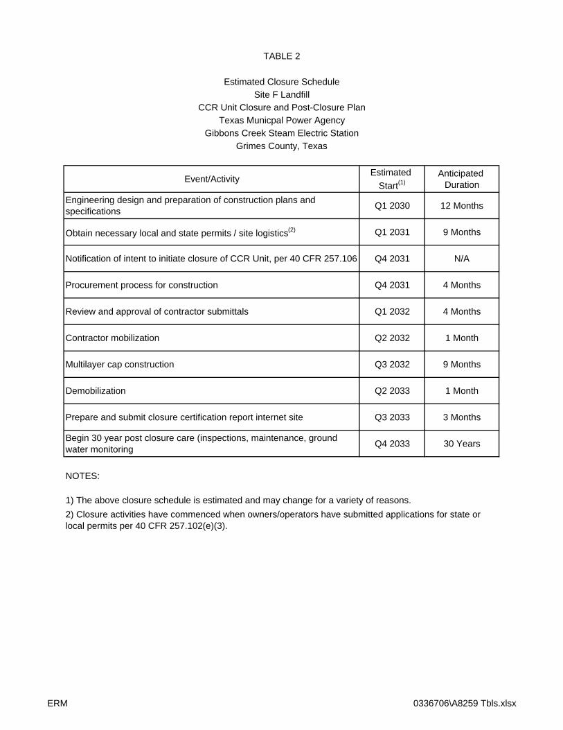

Environmental Resources Management 206 East 9th Street, Suite 1700
Austin, Texas 78701 (512) 459-4700
Figures and Drawings
October 2016 Project No. 0336706
0 1000 2000
SCALE FEET
BASE MAP NOTES:
1. TOPOGRAPHY: SURFACE CONTOURS ARE BASED ON AN
AERIAL SURVEY OBTAINED BY THE TMPA FROM CDS/MUERY
SERVICES, INC.,\BIBBONS, DWG., 09/15/03.
2. AERIAL SURVEY REFERENCE MARKERS: REFERENCE
MARKERS USED FOR SITE A LANDFILL SURVEYS ARE AS
FOLLOWS:
MARK
TMPA 1
TMPA 2
TMPA 3
TMPA 4
DESCRIPTION
1/2" IRON ROD
W/RED CAP
1/2" IRON ROD
W/RED CAP
1/2" IRON ROD
W/RED CAP
1/2" IRON ROD
W/RED CAP
NORTH
10,221,597.53
10,213,545.19
10,237,953.03
10,230,743.48
EAST
3,628,876.61
3,642,123.31
3,659,938.58
3,669,915.83
ELEV.
339.19
255.55
308.38
353.37
SHEET NO.REV.:
W.O.NO.:DATE:
DRAWN:DESIGN:SCALE:
CHKD.:
ofH:\DWG\J15\0312226_0024131b204.dwg, 10/19/2015 12:14:19 PM10/19/2015
ER
M-S
ou
th
we
st, In
c. T
X P
E F
irm
N
o. 2
39
3
C. Johnson EFCAS SHOWN
FIGURE 1
SITE BASE MAP
Texas Municipal Power Agency
Gibbons Creek Steam Electric Station
Carlos, Texas
0 200 400
SCALE FEET
CHKD.:
REV.:
DRAWN:
SCALE:DATE:
DESIGN:
H:\DWG\H16\0312226a100.dwg, 8/23/2016 3:39:53 PM
8/23/2016
ER
M-S
ou
th
we
st, In
c. T
X P
E F
irm
N
o. 2
39
3
FIGURE 2
CAP CONCEPT GRADING PLAN
ASH PONDS
CCR UNITS CLOSURE AND POST CLOSURE PLAN
TEXAS MUNICIPAL POWER AGENCY
GRIMES COUNTY, TEXASEDM CAK EDM
AS SHOWN
0 200 400
SCALE FEET
CHKD.:
REV.:
DRAWN:
SCALE:DATE:
DESIGN:
H:\DWG\H16\0312226a100.dwg, 8/23/2016 3:46:13 PM
8/23/2016
ER
M-S
ou
th
we
st, In
c. T
X P
E F
irm
N
o. 2
39
3
FIGURE 3
CAP CONCEPT GRADING PLAN
SCRUBBER SLUDGE POND
CCR UNITS CLOSURE AND POST CLOSURE PLAN
TEXAS MUNICIPAL POWER AGENCY
GRIMES COUNTY, TEXASEDM CAK EDM
AS SHOWN
ABBREVIATIONS
BDY. BOUNDARY
ETOS EXTERIOR TOE OF SLOPE
ETOB EXTERIOR TOP OF BANK
EXIST. EXISTING
EXT. EXTERIOR
F.G. FINISHED GRADE
H HORIZONTAL
ITOB INTERIOR TOP OF BANK
PROP. PROPOSED
TYP. TYPICAL
V VERTICAL
0 500 1000
SCALE FEET
CHKD.:
REV.:
DRAWN:
SCALE:DATE:
DESIGN:
H:\DWG\H16\0312226a100.dwg, 8/23/2016 3:53:29 PM
8/23/2016
ER
M-S
ou
th
we
st, In
c. T
X P
E F
irm
N
o. 2
39
3
FIGURE 4
CAP CONCEPT GRADING PLAN
SITE F LANDFILL
CCR UNITS CLOSURE AND POST CLOSURE PLAN
TEXAS MUNICIPAL POWER AGENCY
GRIMES COUNTY, TEXASEDM CAK EDM
AS SHOWN


![A€¦ · Web viewA11.A.5(a) Closure of Container Storage Areas [R 299.9614 and 40 CFR 264.178] This section describes the procedures for closure of [Unit Name]. The general closure](https://img.pdfslide.net/doc/110x75/5f46552b474eae6e982da6ff/a-web-view-a11a5a-closure-of-container-storage-areas-r-2999614-and-40-cfr.jpg)