Embed Size (px)
Citation preview

Newfoundland and Labrador Hydro
Lower Churchill Project Pre-Feed Engineering Services
Muskrat Falls Hydroelectric Project
MF1050 – Spillway Design Review
FINAL
Document No: 722850-MF1050-40ER-0001-00
December 2007
Muskrat Falls Project - CE-16 Rev. 1 (Public) Page 1 of 59

Newfoundland & Labrador Hydro
LOWER CHURCHILL PROJECT
TECHNICAL REPORT
MF1050 – SPILLWAY DESIGN REVIEW
Document No: 722850-MF1050-40ER-0001-00
FINAL December 2007 Prepared by: Jean Gagnon Verified by: David Robinson Approved by: Bert Peach
Muskrat Falls Project - CE-16 Rev. 1 (Public) Page 2 of 59

Lower Churchill Project December 2007 Pre-Feed Engineering Study – Muskrat Falls MF1050 – Spillway Design Review Project No. 722850
SNC-Lavalin Inc. Page i
TABLE OF CONTENTS
Page No.
Executive Summary ......................................................................................................................iii
1 INTRODUCTION ...................................................................................................................1 2 SCOPE ..................................................................................................................................2 3 DESCRIPTION OF VARIANT 10 ..........................................................................................3 4 METHODOLOGY ..................................................................................................................4 5 DESIGN CONSIDERATIONS AND CRITERIA.....................................................................6
5.1 Powerhouse..................................................................................................................6 5.1.1 Arrangement ....................................................................................................6 5.1.2 Schedule ..........................................................................................................6
5.2 Spillway Structure.........................................................................................................7 5.3 North Dam ....................................................................................................................7
5.3.1 General ............................................................................................................7 5.3.2 Inflatable Rubber Dam Segment ......................................................................8 5.3.3 Fixed Crest Segment .......................................................................................8
5.4 Design Flow Conditions................................................................................................9 5.4.1 Diversion Phase – Non-Winter.........................................................................9 5.4.2 Diversion Phase – Winter.................................................................................9 5.4.3 Completion of Rollways..................................................................................10 5.4.4 Permanent Operations ...................................................................................11
6 MECHANICAL CONSTRAINTS FOR GATES....................................................................12 6.1 Upstream Stoplogs .....................................................................................................12 6.2 Surface Vertical Gates................................................................................................12 6.3 Submerged Vertical Gates .........................................................................................14 6.4 Submerged Radial Gates ...........................................................................................14
7 ALTERNATIVE SCHEMES.................................................................................................16 7.1 General.......................................................................................................................16 7.2 Surface Vertical Gate Schemes (1a to 1f) ..................................................................17 7.3 Submerged Vertical Gate Schemes (2a and 2b)........................................................17 7.4 Submerged Radial Gate Schemes (3a and 3b)..........................................................18 7.5 Technical Summary....................................................................................................19
8 QUALITATIVE EVALUATION.............................................................................................21 8.1 Surface Vertical Gate Schemes .................................................................................21 8.2 Submerged Vertical Gate Schemes ...........................................................................22 8.3 Submerged Radial Gate Scheme...............................................................................22
9 QUANTITATIVE EVALUATION ..........................................................................................24 9.1 Construction Phase ....................................................................................................24 9.2 Operations Phase.......................................................................................................25 9.3 Comparative Costs .....................................................................................................25
Muskrat Falls Project - CE-16 Rev. 1 (Public) Page 3 of 59
10 RECOMMENDATIONS .......................................................................................................27 List of Tables Table 6-1: Existing Large Submerged Radial or Segment Gates ..............................................15 Table 7-1: Description of Spillway Schemes.............................................................................. 20 List of Figures Figure 6-1: Maximum Acceptable Head for Vertical Gates on Fixed Wheels & Sliding Stop Logs
.............................................................................................................................................13 Appendices: Appendix A Hydrologic and Hydraulic Data Appendix B Comparative Costs Appendix C Construction Schedule Appendix D Views and Drawings
Muskrat Falls Project - CE-16 Rev. 1 (Public) Page 4 of 59

Lower Churchill Project December 2007 Pre-Feed Engineering Study – Muskrat Falls MF1050 – Spillway Design Review Project No. 722850
SNC-Lavalin Inc. Page iii
EXECUTIVE SUMMARY In WTO MF1010 - Review of Variants, a layout and cost review was carried out on the short-
listed variants presented in the January 1999 Final Feasibility Study for Muskrat Falls1, in
particular Variants 7, 10 and 11.
Variant 7 was, at the time of the above report, the recommended variant of choice. However, in
the interim period a highway bridge was constructed across the Churchill River about 18 km
downstream of the Muskrat Falls site. With this crossing, it would be possible to achieve
construction access to the south shore of the Muskrat Falls site within three months of the
project start, and such access would enhance Variant 10 and, to a lesser extent, Variant 11
relative to Variant 7.
From the MF1010 study came the recommendation that Variant 10, through a significantly
shorter construction schedule than either Variants 7 or 11, was the current variant of choice.
Variant 10 includes a three-bay gated spillway, an inflatable rubber dam and a fixed crest
overflow spillway. The river diversion would be through the gated spillway structure.
In this study, the Variant 10 spillway facilities were to be developed further, with particular
interest in the use of an inflatable rubber dam, if such a dam were to be part of the
recommended scheme.
As the gates included in Variant 10 were larger than any known installation, an array of gate
sizes were identified which conformed to current maximum gate size parameters, including both
surface and submerged gates, vertical and radial gate types.
The design parameters for the spillway facilities were that the gated spillway:
• Must pass the construction design flood without overtopping the upstream cofferdam
required for the north dam construction;
• Must control the winter diversion flows to maintain a forebay level at elevation 24 m for
frazil ice control;
1 Final Feasibility Study, Muskrat Falls Hydroelectric Development, January 1999, SNC-AGRA.
Muskrat Falls Project - CE-16 Rev. 1 (Public) Page 5 of 59
• Must be able to pass the PMF along with the overflow facilities of the north dam, which
may include a rubber dam and/or fixed crest spillway, without exceeding a forebay level
of elevation 44 m.
The study of a number of alternative spillway layouts resulted in a shortlist of the following cases:
● Scheme 1a 3 bay gated spillway, surface vertical gates 13.75 m wide by 19.4 m high, rubber dam 330 m long and fixed crest 115 m long;
● Scheme 1c 5 bay gated spillway, surface vertical gates 10.4 m wide by 21.5 m high, no rubber dam, fixed crest 429.5 m long;
● Scheme 1f 5 bay gated spillway, surface vertical gates 13.75 m wide by 17.7 m high, no rubber dam, fixed crest 409.3 m long;
● Scheme 3b 4 bay gated spillway, submerged radial gates 12.5 m wide by 14.8 m high, no rubber dam, fixed crest 433.2 m long.
On a quantitative basis, the least expensive case is Scheme 3b. As this is the least complicated
arrangement for constructability, requires no rubber dam or overhead service bridge, and has
lower operational costs than cases with a rubber dam, it is the recommended scheme of choice.
Muskrat Falls Project - CE-16 Rev. 1 (Public) Page 6 of 59

Lower Churchill Project December 2007 Pre-Feed Engineering Study – Muskrat Falls MF1050 – Spillway Design Review Project No. 722850
SNC-Lavalin Inc. Page 1
1 INTRODUCTION
In WTO MF1010 - Review of Variants (MF1010), a layout and cost review was
carried out on the variants presented in the January 1999 Final Feasibility Study for
Muskrat Falls1, particularly Variants 7, 10 and 11. The review was to confirm the
optimum layout for the project, based on:
• The cofferdam requirements;
• Access roads and new highway bridge;
• Capital costs.
The findings were:
• That the capital costs of all three variants were very similar;
• Variant 10 offered a considerably shorter construction schedule;
• Variant 10 also offered some alternatives for the spillway and site access.
Drawing No. 722850-MF1010-41DD-0003, Arrangement of Principal Structures, Plan
and Profile depicts the layout of Variant 10 and the associated spillway structures.
In this study, the Variant 10 spillway facilities were to be developed further, with
particular interest in the use of an inflatable rubber dam, if such a dam were to be
part of the recommended scheme.
1 Ibid.
Muskrat Falls Project - CE-16 Rev. 1 (Public) Page 7 of 59
2 SCOPE
The work consisted of a review of the current layout and design concepts for the
spillway structures including the gated spillway, the south RCC overflow dam and the
north RCC dam with the rubber dam crest. The purpose of this review was to
confirm the design concepts, specifically for rubber dams, and to confirm the
discharge capacity of the spillway structures in view of the updated Probable
Maximum Flood (PMF), which will be determined by others.
With respect to the rubber dam, the review included:
• Confirming the status of technology development for rubber dams,
• Collecting technical data on rubber dams,
• Collecting performance data from owners of existing rubber dams, operating
under similar conditions to those at Muskrat, and
• Confirming the design concept proposed for Muskrat Falls, based on the
foregoing.
Muskrat Falls Project - CE-16 Rev. 1 (Public) Page 8 of 59

3 DESCRIPTION OF VARIANT 10
In MF1010, the spillway, powerhouse and south dam of Variant 10 would be
constructed in the south abutment, complete with approach and discharge channels
immediately above the lower falls. The river valley would be closed by the
construction of an RCC dam from the spillway to the north abutment.
For the initial phase of construction, the river would remain in its normal channel until
Year 3, when it would be diverted through the spillway sluices, temporarily left
without rollways. The spillway would have sufficient capacity to pass the summer
peak construction floods and would have gated control to maintain high forebay
levels in winter for frazil ice control. Upstream and downstream cofferdams would
allow dewatering of the river channel for construction of the north dam during Year 4.
The spillway facilities would include a three-bay gated spillway with the gate sills on
top of rollways, and a five sectioned rubber dam plus a section of fixed crest overflow
spillway located on the north RCC dam. In order of priority, the gated sluices would
be operated first, then if required, the rubber dam and then the fixed crest weir. All
three of the spillway components would be used to pass the PMF.
First power is expected to be available in July of Year 5, 55 months after project
start, as shown in the construction schedule included in Appendix C.
Construction access to the south shore may be from a temporary bridge located
above the upper falls, or by an 18 km road from the existing highway bridge
downstream of the project site. If the temporary bridge is not constructed, a
temporary link between the south and north shores would be required over a small
bridge crossing the diversion channel, the upstream cofferdam and a low-level
rockfill roadway around the base of the rock knoll at the north abutment.
Permanent access to the power facilities may be from the north over the top of the
north dam, spillway, intake structure and south dam, or alternatively, from the
upgraded south shore construction road.
Muskrat Falls Project - CE-16 Rev. 1 (Public) Page 9 of 59

4 METHODOLOGY
The layout of the structures adopted for Variant 10 in MF1010 was purposely made
similar to that of Variant 7, except for location, to simplify the comparison of the
schemes. Having determined that Variant 10 ranked the best for cost and time, the
next steps involved re-assessing the design for current practice and experience.
For example, in 1998, RCC overflow dams had conventional concrete on their
downstream slopes, whereas today, the slope is the natural stepped RCC. This has
been adopted for this study, with resulting cost savings from replacing conventional
concrete with lower priced RCC.
Gate sizes and weights are also an important consideration. In 1998, the gates
selected were 13.75 m by 20.2 m, 5% larger than those in the Lobstick Control
Structure in the Churchill Falls system. Using current practices for determining the
maximum practical size of gates, alternative gate sizes were assessed. The
alternative of using submerged gates was also evaluated further, and a new
configuration was developed. In addition, since radial gates are normally less
expensive than vertical gates, this alternative was studied.
The constructability of the layout was looked at closely with respect to the stability of
the structures during construction, to ensure that required access is available to the
site, and to ensure that areas needing to be dewatered have suitable cofferdams or
guide walls included in the design.
Site access was also considered, both temporary and permanent. Early access to
the south shore is mandatory if the construction schedule provided in MF1010 is to
be met. The necessity for the transfer of materials between the north and south
shores during construction requires a site link, by bridge or over the upstream
cofferdam. Permanent access to the power facilities may be from the north or south,
but utilizing a south shore access road would allow the deletion of the high level
permanent access road excavated in rock around the rock knoll at the north
abutment.
Muskrat Falls Project - CE-16 Rev. 1 (Public) Page 10 of 59

Section 5 of this report records the main input and design criteria used in the study,
Section 6 reviews the mechanical constraints associated with the use of various gate
options, and Section 7 describes the alternative layout arrangements.
Sections 8 and 9 outline the qualitative and quantitative assessments of the
alternatives, and Section 10 identifies the most attractive schemes.
Muskrat Falls Project - CE-16 Rev. 1 (Public) Page 11 of 59

5 DESIGN CONSIDERATIONS AND CRITERIA
5.1 POWERHOUSE
5.1.1 Arrangement
The design of the powerhouse, except for its location, is unchanged since the
January 1999 report, which shows it to contain four (4) generating units, three (3) of
which are 206 MW propeller units, and the other a 206 MW Kaplan unit. The intake
structure is shown close-coupled with the powerhouse, which has concrete spiral
cases. It is 187.5 m long, including a 43 m long service bay.
In the Variant 10 arrangement, the powerhouse would be located on the right
abutment to allow it, along with the spillway structure to be constructed in the dry.
The total available length between the powerhouse left wall and the north end of the
north dam would be approximately 528 m. This length includes the 10 m wide
concrete bulkhead dam located between the powerhouse and the right spillway wall
and a 20 m long north-end abutment. Of this length, about 498 m can be utilized for
a combination of gated spillway, inflatable rubber dam and fixed crest overflow dam
as a spillway system to permit the passage of the PMF.
The powerhouse could be moved further south into the south abutment in order to
increase the space available for the spillway facilities, however, the quantity of rock
to be excavated for the approach and discharge channels, as well as the
powerhouse foundations, would increase considerably.
5.1.2 Schedule
With reference to the construction schedule in Appendix C, at the time of diversion in
July of Year 3, the intake structure and powerhouse first stage concrete would be
substantially complete. The bulkhead dam between the gated spillway and the
powerhouse would be complete.
It is intended that rock plugs be left in place in the approach and discharge channels
following diversion until late in Year 4, about the time when the units have met their
“pit free” dates. Guide walls on the south side of the spillway structure approach and
Muskrat Falls Project - CE-16 Rev. 1 (Public) Page 12 of 59

discharge channels are required to maintain the intake and draft tubes in a dry state.
The intake gates may take an additional three (3) to four (4) months to complete, and
the turbine erection is expected to take another year and one-half.
5.2 SPILLWAY STRUCTURE
The spillway structure would be located on the north side of the powerhouse and the
10 m long bulkhead dam. As originally conceived, it would contain three (3) 13.75 m
wide sluices with rollways having a sill elevation of 18.8 m, and with piers/sidewalls 4
m thick, an overall width of 57.25 m. The vertical gates would be 20.2 m high.
The spillway is the primary structure of this study, which may be revised by varying
the size and number of gates, by changing the operation of the gates from surface to
submerged, and by changing the type of gates, vertical to radial.
The top elevation of the base slab of the spillway structure was set at 5 m for
diversion flows and/or as the permanent base for the submerged gate alternatives.
Rollways required for surface vertical gate alternatives would be added to the base
slab during the latter stage of construction.
The spillway, along with the 10 m wide bulkhead dam, is intended to be constructed
simultaneously with the intake structure and the powerhouse first stage concrete.
Prior to diversion, a gravity dam, possibly of RCC would be constructed on the north
side of the spillway at right angles to the main dam axis as a closure dam for the
upstream cofferdam. This dam would provide additional stability for the north wall of
the spillway structure. The south sidewall of the spillway structure would be
supported by the 10 m wide bulkhead dam and the intake structure.
5.3 NORTH DAM
5.3.1 General
The north dam is an overflow RCC gravity structure that can be configured as part of
the spillway facilities with a rubber dam and fixed crest sections. About 498 m, less
the width of the spillway structure, is available for the north dam spillway. With the
gated spillway providing the primary spillway flow control; secondary control would
Muskrat Falls Project - CE-16 Rev. 1 (Public) Page 13 of 59

be by the inflatable rubber dam segment (where applicable), with the balance by the
fixed crest segment.
In the case where permanent access is from the north, there would be an overhead
bridge set on piers over the full length of the north dam, which would reduce the
effective spillway length of inflatable rubber crest and/or fixed crest. In the case
where permanent access is from the south shore, a lightweight overhead bridge deck
would be required over the rubber dam section for servicing, but not over the fixed
crest section.
5.3.2 Inflatable Rubber Dam Segment
For the alternatives studied herein, the inflated crest of the rubber dam was set at
elevation 39.5 m, and the deflated level at elevation 37.1 m and 35.9 m for different
alternatives.
The rubber dam will be fabricated to suit the installation, but would generally
comprise of 33 m long sections, separated by 2 m wide piers at 35 m centers.
The advantage of the rubber dam is that it offers a high unit discharge capacity when
deflated, at relatively low cost, which displaces higher unit cost gated spillway
capacity. The main disadvantage is that in the event of replacement, it could mean a
complete plant shutdown if the foundation sill is below the minimum recommended
operating level of the plant.
5.3.3 Fixed Crest Segment
The remaining length of the north dam, not occupied by the rubber dam, would be
used as a fixed crest overflow spillway. The crest would be set at elevation 39.5 m,
the same as the inflated crest of the rubber dam, for wind surge, waves and a small
allowance for forebay control variation.
Muskrat Falls Project - CE-16 Rev. 1 (Public) Page 14 of 59
5.4 DESIGN FLOW CONDITIONS
5.4.1 Diversion Phase – Non-Winter
As shown in the summary implementation schedule in Appendix C, two (2) years
would be needed to build the spillway for passage of the diversion flows: one (1)
spring flood, two (2) consecutive summers. It is assumed that no construction would
be going on during the winter. The maximum forebay water level is based on the
following operating conditions:
• The 1:20 year total peak inflow to Muskrat Falls, based on a 5% risk for a
diversion over a single peak flood season. Since the 1:20 year inflow was
unavailable, the 1:40 year flood value of 5,300 m3/s was used;
• All spillway bays would be built and the gates and hoists operational;
• The rollways for the schemes with vertical surface gates would be temporarily left
out, and all bays would have a horizontal invert at El. 5.0 m;
• The north dam would not yet be constructed;
• The upstream cofferdams would have at least a 2.0 m freeboard protection and
the downstream cofferdam would have a 1.0 m freeboard; and
• The tail water elevation for the design flow of 5,300 m3/s would be 5.8 m.
Refer to Appendix A for hydrological and hydraulic data and criteria.
5.4.2 Diversion Phase – Winter
All conditions presented in Section 5.4.1 are applicable in addition to the following:
• The forebay has to be maintained at or near elevation 24 m in order to create
upstream conditions favourable for the creation of an ice cover to minimize frazil
ice formation during the diversion phase;
• The most difficult condition for winter regulation at elevation 24 m is when the
diversion flow is very low. Based on the daily flow series taking into
Muskrat Falls Project - CE-16 Rev. 1 (Public) Page 15 of 59

consideration Churchill Falls regulation and no regulation at Gull Island (Figure
A-2 in Appendix A) a minimum design flow of 800 m3/s was considered; and
• For winter forebay regulation with small inflows at Muskrat Falls, only one
spillway gate is recommended to be operated and the minimum gate opening
should be in excess of 10% of the gate height in order to minimize vibration.
5.4.3 Completion of Rollways
In some of the spillway schemes, the rollways would be finalized during the latter
part of the diversion period, but prior to impounding. The north dam would be nearly
complete. The rollways would be constructed sequentially behind stoplogs during
the off-peak flood season to minimize the forebay level and the required height of the
stoplogs. The stoplog guides would extend down to the invert at elevation 5.0 m. As
each rollway is completed however, the level of the forebay would increase during
the construction of the next rollway.
For completion of the schemes with rollways, two (2) distinct locations for upstream
stop log guides were considered in order to minimize the overall weight for the
upstream stoplogs:
• Conventional permanent guides and stoplogs located immediately upstream of
the spillway gates, on the top of the rollways, for the long term maintenance;
• Temporary guides located upstream of the rollways, required for the finalization
of the rollways.
The upstream stoplogs required for construction of the rollways comprise two (2)
types of stop logs:
• Stoplog sill upstream of the main gate sill, near the top of the rollway for the
permanent stoplogs;
• Stoplog sill upstream of the rollway on the base slab for the temporary stoplogs.
Muskrat Falls Project - CE-16 Rev. 1 (Public) Page 16 of 59
All upstream stop logs (temporary and permanent) would be handled from the
spillway service bridge.
The maximum forebay water level for the design of the height of the temporary
upstream stop logs was computed for the following operating conditions:
• A total peak inflow to Muskrat Falls of 3,000 m3/s during the summer and fall;
• All spillway bays, gates, hoists and rollways would be completed and operational
except for one (1) bay under stop logs;
• Stop logs or equivalent would be in place to protect the power intake against
forebay levels up to about El. 33 m;
• The top of the upstream stop logs set in the temporary upstream guides would be
0.5 m higher than the computed maximum forebay water elevation.
5.4.4 Permanent Operations
The extreme forebay water level during the PMF would be El. 44.0 m under the
following operating conditions:
• The PMF presents a total peak inflow of 22,100 m3/s at Muskrat Falls;
• All spillway bays would be operational and completed with gates, hoists, rollways
and/or walls;
• Tail water would be at El. 12.2 m;
• The Muskrat powerhouse would not be operational; and
• The north dam would be operational.
Due to high flow velocities downstream of the north dam and gated spillway, the
natural rock surface would need to be lined with concrete from the downstream toe
of the structures to the edge of the river tailpond.
Muskrat Falls Project - CE-16 Rev. 1 (Public) Page 17 of 59
6 MECHANICAL CONSTRAINTS FOR GATES
6.1 UPSTREAM STOPLOGS
Considering practical mechanical constraints for manufacturing and operation, the
maximum head acceptable on the sill of sliding stop logs for various spillway bay
widths would be (see Curve 2, Figure 6-1):
• 47 m of head with a gate width of 10.5 m;
• 34 m of head with a gate width of 12.5 m; and
• 28 m of head with a gate width of 13.75 m.
For schemes with submerged vertical and/or radial gates, the maximum hydrostatic
head on the sill during operation would be 34 m (FSL 39.0 – 5.0 = 34.0 m). The
maximum width of the spillway bays based on stoplog limitations for these schemes
was therefore set at 12.5 m (see Curve 2, Figure 6-1).
Each stop log lift is limited to about 20 t.
6.2 SURFACE VERTICAL GATES
Based on existing spillway surface gates built for the La Grande Phase 1 & 2, a
maximum gate weight of about 160 t and a hoisting capacity of 200 t was used for
the present comparative analysis. The following maximum vertical gate dimensions
were considered:
• 10.5 m W x 24.5 m H;
• 11.5 m W x 23.0 m H;
• 12.2 m W x 21.5 m H; and
• 13.75 m W x 19.4 m H.
The above gate heights include a 0.5 m freeboard.
Muskrat Falls Project - CE-16 Rev. 1 (Public) Page 18 of 59

SNC-Lavalin Inc. Page 13
Lower Churchill Project December 2007 Pre-Feed Engineering Study – Muskrat Falls MF1050 – Spillway Design Review Project No. 722850
Figure 6-1: Maximum Acceptable Head for Vertical Gates on Fixed Wheels & Sliding Stop Logs
“Based on in-house SNC-Lavalin standards and Hydro Quebec practice”
Muskrat Falls Project - CE-16 Rev. 1 (Public) Page 19 of 59

wer Churchill Project December 2007eed Engineering Study – Muskrat Falls MF1050 – Spillway Design Review Project No. 722850
SNC-Lavalin Inc. Page 14
6.3 SUBMERGED VERTICAL GATES
Given the maximum hydrostatic head of 34 m on the sill (FSL 39.0 – 5.0 = 34.0 m)
and the mechanical limitations, the maximum acceptable width of submerged vertical
gates would be 10.5 m (see Curve 1, Figure 6-1).
The maximum height of the gate would be 10.5 m in order to limit the gate weight to
about 160 t.
6.4 SUBMERGED RADIAL GATES
The hydrostatic pressure of 34 m on the upstream stop logs sill limits the width of
each spillway sluice and the submerged radial gate to 12.5 m (see Curve 1, Figure 6-
1).
For the present comparative analysis, the maximum hydrostatic pressure on the gate
was limited to 50 MN (see Table 6-1) and the maximum acceptable gate height was
15.5 m.
No overflow was permitted over the spillway vertical and/or radial gates.
The radial gates would be operated by hydraulic cylinders or individual cable hoists.
Stoplogs may be handled by a gantry or mobile crane.
The service bridge would be located on the upstream side of the control structure.
Muskrat Falls Project - CE-16 Rev. 1 (Public) Page 20 of 59

Table 6-1: Existing Large Submerged Radial or Segment Gates Year Project Qty Span
(m)
Height
(m)
Area
(m3)
Head on
sill (m)
Hydrostatic
load (MN)
Manufacturer
1965 Mangala 9 10.97 13.00 142.61 48.50 58.76 Krupp
1994 Berke 2 10.00 10.30 103.00 63.00 58.45 VA TECH Hydro
1972 Tarbela 4 4.88 7.30 35.62 135.60 46.11 VA TECH Hydro
1965 Tweeriivieren 2 8.38 5.18 43.41 103.48 42.96 Kure
1981 Tabka 5.50 12.00 66.00 67.00 39.50
1969 Cabora Bassa 8 6.00 7.80 46.80 82.30 35.99 Sorefame
1970 Reza Shah Kabir 4 8.00 6.70 53.60 71.50 35.83 ALSTOM
1979 Jebba 6 12.00 9.50 114.00 36.00 34.95 Mitsubishi
Wuquiangxi 1 9.00 12.00 108.00 38.70 34.64
1962 Roseires 5 6.00 11.30 67.80 55.30 33.02 ALSTOM
Toktogul 5.00 6.00 30.00 112.20 32.14
Nourek 5.00 6.00 30.00 110.00 31.49
Sayano-Sushenskoe 5.00 5.50 27.50 116.70 30.74
1949 Castelo do Bode 2 14.00 8.50 119.00 30.00 30.06 ALSTOM
1981 Magat 2 6.00 12.50 75.00 46.50 29.61 VA TECH Hydro
1991 Aguamilpa 6 12.00 19.34 232.08 22.40 28.98 VA TECH Hydro
1962 Roseires 7 10.00 13.20 132.00 27.50 27.06 ALSTOM
1972 P. K. Le Roux 4 15.00 9 135.00 23.00 24.50 Sorefame
1974 Saddam 2 5.00 7.50 37.50 68.00 23.64 VA TECH Hydro
1960 Garrison 3 5.49 7.49 41.12 58.20 21.97
1948 Chastang 2 13.60 9.50 129.20 22.00 21.86 ALSTOM
1974 Sobradinho 12 9.80 7.50 73.50 33.87 21.72 VOITH
1960 Mechra-Klila 4 16.00 12.30 196.80 16.90 20.75 ALSTOM
Miranda 4 24.00 8.73 209.52 14.00 19.80 ALSTOM
1965 Achi 1 6.50 4.30 27.95 74.00 19.70 Waagner-Biro
1961 Khashm El Girba 7 7.00 7.30 51.10 42.50 19.48 Riva-Calzoni
Muskrat Falls Project - CE-16 Rev. 1 (Public) Page 21 of 59
7 ALTERNATIVE SCHEMES
7.1 GENERAL
Due to the number of variables, i.e.:
• number and size of gates in the gated spillway;
• inclusion or not of an inflatable rubber dam;
• height and length of the rubber dam;
• crest elevation and length of the fixed crest spillway;
a large number of alternatives are possible which may satisfy the main criteria of
being able to:
• pass the required construction floods through the diversion channels of the gated
spillway without exceeding the upstream cofferdam elevation;
• maintain the forebay water level at elevation 24 m in winter to promote the
formation of an upstream ice cover;
• pass the PMF without exceeding the maximum flood level.
Using the maximum gate size criteria of the previous section, and the Variant 10
base case design, a limited number of preferred spillway schemes were selected for
study. A comparative evaluation, qualitative and quantitative, was carried out on the
preferred schemes and is presented in Sections 9 and 10.
Whenever possible, the width of 13.75 m was selected for the spillway bays. This
compares with the existing Lobstick Control Structure and the proposed Gull Island
Development.
All spillway schemes presented in Table 8-1 are considered to be technically feasible
and only differ by their various characteristics. Brief descriptions of the schemes
follow.
Muskrat Falls Project - CE-16 Rev. 1 (Public) Page 22 of 59
7.2 SURFACE VERTICAL GATE SCHEMES (1A TO 1F)
The surface vertical gate schemes all have fixed wheel gates. The rollways would
be built in the latter stage of the diversion period. The gates would be required for
winter flow regulation during the diversion period while operating on sills at elevation
5.0 m.
Schemes 1a and 1b have three (3) gated spillway bays, an inflatable rubber dam
plus a length of fixed crest overflow dam with the crest set at elevation 39.5 m. The
rubber bladder height would be 2.4 m for Scheme 1a and 3.6 m for Scheme 1b.
Schemes 1c to 1f have no rubber dam, but have five (5) gated spillway bays and a
length of fixed crest overflow dam with the crest at elevation 39.5 m. Gate width
varies from 10.5 to 13.75 m wide.
There are two (2) upstream stop logs guides and two (2) sets of upstream stop logs:
one (1) permanent and one (1) temporary.
7.3 SUBMERGED VERTICAL GATE SCHEMES (2A AND 2B)
The submerged vertical gate schemes have fixed wheel gates with upstream seals
against a vertical wall. All bays, vertical headwalls and spillway equipment would be
completed prior to commencement of the diversion phase.
As no rollways are required, there would only be one (1) upstream stop log guide
and permanent stop logs with downstream seals against the vertical wall with sill at
El. 5.0 m. The maximum hydrostatic head on the upstream stop log sill would be
34.0 m and for this reason the gate width was limited to a maximum of 10.5 m. Both
schemes 2a and 2b have the capacity to control the forebay level during winter, pass
the design construction flood and, in permanent operation, pass the PMF.
Scheme 2a has a four (4) bay gated spillway with the permanent gate sill at elevation
5.0 m. It has a 2.4 m high rubber dam with an inflated crest elevation of 39.5 m, 325
m long (10 bays). A 116 m long fixed crest overflow weir at elevation 39.5 m
completes the north dam. A service bridge would be required over the rubber dam.
Muskrat Falls Project - CE-16 Rev. 1 (Public) Page 23 of 59

Scheme 2b has a five (5) bay gated spillway with the permanent gate sill at elevation
5.0 m. It has no rubber dam, and a fixed crest overflow section on the north dam
440 m long with the crest at elevation 39.5 m. No service bridge would be required
over the fixed crest dam.
7.4 SUBMERGED RADIAL GATE SCHEMES (3A AND 3B)
The submerged radial gate schemes have upstream seals against a vertical
headwall. All bays, vertical headwalls and spillway equipment would be required to
be completed prior to the commencement of the diversion phase. The gates would
have permanent sills at elevation 5.0 m. Two (2) such schemes were identified:
• Scheme 3a, comprising a three (3) bay gated spillway, with submerged radial
gates 10.5 m wide by 10.5 m high, a rubber dam 2.4 m high and 120 m long, and
a fixed crest overflow section on the north dam with the weir crest at elevation
39.5 m.
• Scheme 3b, comprising a four (4) bay gated spillway, with submerged radial
gates 12.5 m wide by 14.8 m high, no rubber dam, and a fixed crest overflow
section on the north dam with the weir crest at elevation 39.5 m.
There would only be one (1) upstream guide and the stop logs would have
downstream seals against the vertical wall with the sill at elevation 5.0 m. The
maximum hydrostatic head would be 34.0 m on the upstream stop log sill and for that
reason the maximum width of the spillway bays was set at 12.5 m. A height of 15.5
m for the Scheme 3a gates would result in a maximum acceptable gate weight of
160 t.
Schemes 3a and 3b can regulate the forebay during the winter.
For scheme 3b the design flood during the diversion phase is capable of being
spilled with the forebay elevation below elevation 24.0 m. However, for scheme 3a,
the reservoir would be at elevation 25.3 m so would require the upstream cofferdam
to be set at elevation 27.3 m.
Muskrat Falls Project - CE-16 Rev. 1 (Public) Page 24 of 59

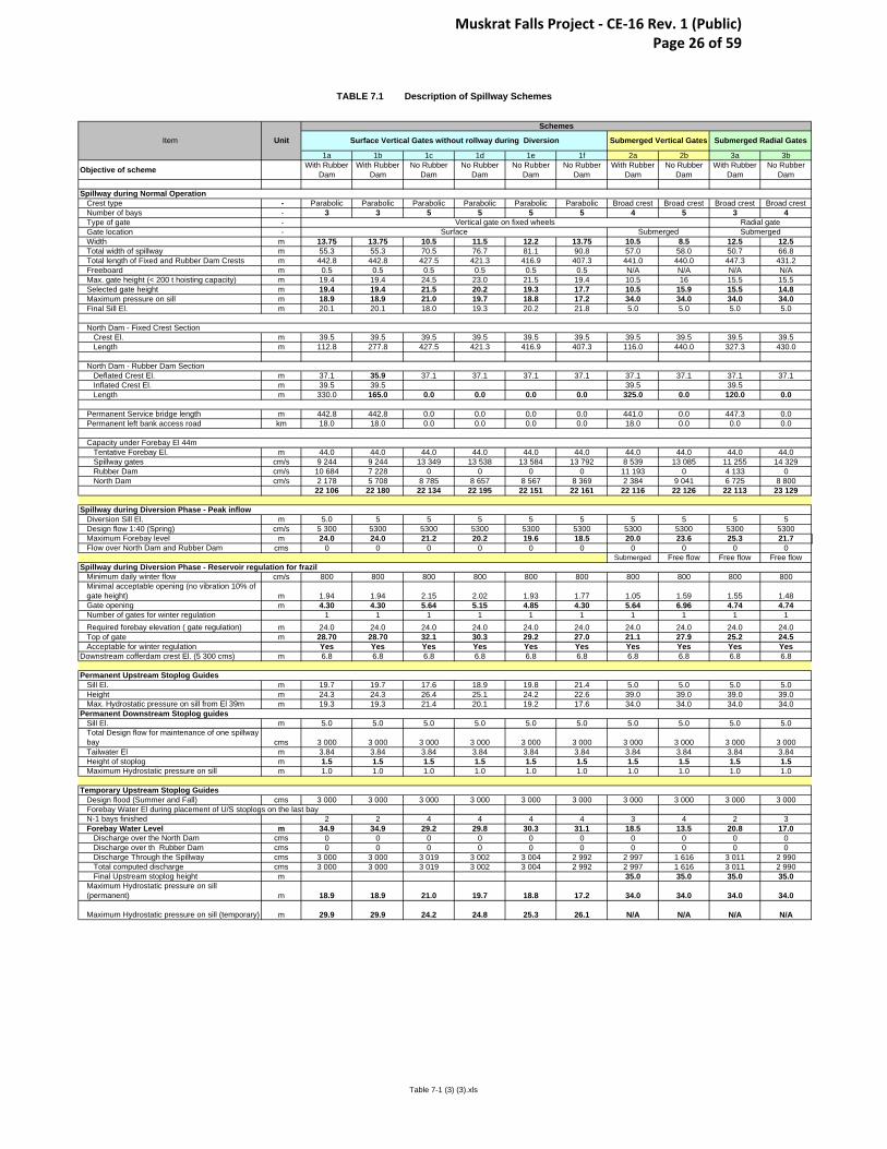
7.5 TECHNICAL SUMMARY
Table 7-1 on the following page summarizes the spillway alternatives studied herein.
Muskrat Falls Project - CE-16 Rev. 1 (Public) Page 25 of 59
1a 1b 1c 1d 1e 1f 2a 2b 3a 3b
Objective of scheme With Rubber Dam
With Rubber Dam
No Rubber Dam
No Rubber Dam
No Rubber Dam
No Rubber Dam
With Rubber Dam
No Rubber Dam
With Rubber Dam
No Rubber Dam
Crest type - Parabolic Parabolic Parabolic Parabolic Parabolic Parabolic Broad crest Broad crest Broad crest Broad crestNumber of bays - 3 3 5 5 5 5 4 5 3 4Type of gate -Gate location -Width m 13.75 13.75 10.5 11.5 12.2 13.75 10.5 8.5 12.5 12.5Total width of spillway m 55.3 55.3 70.5 76.7 81.1 90.8 57.0 58.0 50.7 66.8Total length of Fixed and Rubber Dam Crests m 442.8 442.8 427.5 421.3 416.9 407.3 441.0 440.0 447.3 431.2Freeboard m 0.5 0.5 0.5 0.5 0.5 0.5 N/A N/A N/A N/AMax. gate height (< 200 t hoisting capacity) m 19.4 19.4 24.5 23.0 21.5 19.4 10.5 16 15.5 15.5Selected gate height m 19.4 19.4 21.5 20.2 19.3 17.7 10.5 15.9 15.5 14.8Maximum pressure on sill m 18.9 18.9 21.0 19.7 18.8 17.2 34.0 34.0 34.0 34.0Final Sill El. m 20.1 20.1 18.0 19.3 20.2 21.8 5.0 5.0 5.0 5.0
Crest El. m 39.5 39.5 39.5 39.5 39.5 39.5 39.5 39.5 39.5 39.5Length m 112.8 277.8 427.5 421.3 416.9 407.3 116.0 440.0 327.3 430.0
Deflated Crest El. m 37.1 35.9 37.1 37.1 37.1 37.1 37.1 37.1 37.1 37.1Inflated Crest El. m 39.5 39.5 39.5 39.5Length m 330.0 165.0 0.0 0.0 0.0 0.0 325.0 0.0 120.0 0.0
Permanent Service bridge length m 442.8 442.8 0.0 0.0 0.0 0.0 441.0 0.0 447.3 0.0Permanent left bank access road km 18.0 18.0 0.0 0.0 0.0 0.0 18.0 0.0 0.0 0.0
Tentative Forebay El. m 44.0 44.0 44.0 44.0 44.0 44.0 44.0 44.0 44.0 44.0Spillway gates cm/s 9 244 9 244 13 349 13 538 13 584 13 792 8 539 13 085 11 255 14 329Rubber Dam cm/s 10 684 7 228 0 0 0 0 11 193 0 4 133 0North Dam cm/s 2 178 5 708 8 785 8 657 8 567 8 369 2 384 9 041 6 725 8 800
22 106 22 180 22 134 22 195 22 151 22 161 22 116 22 126 22 113 23 129
Diversion Sill El. m 5.0 5 5 5 5 5 5 5 5 5Design flow 1:40 (Spring) cm/s 5 300 5300 5300 5300 5300 5300 5300 5300 5300 5300Maximum Forebay level m 24.0 24.0 21.2 20.2 19.6 18.5 20.0 23.6 25.3 21.7Flow over North Dam and Rubber Dam cms 0 0 0 0 0 0 0 0 0 0
Submerged Free flow Free flow Free flow
Minimum daily winter flow cm/s 800 800 800 800 800 800 800 800 800 800Minimal acceptable opening (no vibration 10% of gate height) m 1.94 1.94 2.15 2.02 1.93 1.77 1.05 1.59 1.55 1.48Gate opening m 4.30 4.30 5.64 5.15 4.85 4.30 5.64 6.96 4.74 4.74Number of gates for winter regulation 1 1 1 1 1 1 1 1 1 1Required forebay elevation ( gate regulation) m 24.0 24.0 24.0 24.0 24.0 24.0 24.0 24.0 24.0 24.0Top of gate m 28.70 28.70 32.1 30.3 29.2 27.0 21.1 27.9 25.2 24.5Acceptable for winter regulation Yes Yes Yes Yes Yes Yes Yes Yes Yes Yes
Downstream cofferdam crest El. (5 300 cms) m 6.8 6.8 6.8 6.8 6.8 6.8 6.8 6.8 6.8 6.8
Sill El. m 19.7 19.7 17.6 18.9 19.8 21.4 5.0 5.0 5.0 5.0Height m 24.3 24.3 26.4 25.1 24.2 22.6 39.0 39.0 39.0 39.0Max. Hydrostatic pressure on sill from El 39m m 19.3 19.3 21.4 20.1 19.2 17.6 34.0 34.0 34.0 34.0
Sill El. m 5.0 5.0 5.0 5.0 5.0 5.0 5.0 5.0 5.0 5.0Total Design flow for maintenance of one spillway bay cms 3 000 3 000 3 000 3 000 3 000 3 000 3 000 3 000 3 000 3 000Tailwater El m 3.84 3.84 3.84 3.84 3.84 3.84 3.84 3.84 3.84 3.84Height of stoplog m 1.5 1.5 1.5 1.5 1.5 1.5 1.5 1.5 1.5 1.5Maximum Hydrostatic pressure on sill m 1.0 1.0 1.0 1.0 1.0 1.0 1.0 1.0 1.0 1.0
Design flood (Summer and Fall) cms 3 000 3 000 3 000 3 000 3 000 3 000 3 000 3 000 3 000 3 000
N-1 bays finished 2 2 4 4 4 4 3 4 2 3Forebay Water Level m 34.9 34.9 29.2 29.8 30.3 31.1 18.5 13.5 20.8 17.0
Discharge over the North Dam cms 0 0 0 0 0 0 0 0 0 0Discharge over th Rubber Dam cms 0 0 0 0 0 0 0 0 0 0Discharge Through the Spillway cms 3 000 3 000 3 019 3 002 3 004 2 992 2 997 1 616 3 011 2 990Total computed discharge cms 3 000 3 000 3 019 3 002 3 004 2 992 2 997 1 616 3 011 2 990Final Upstream stoplog height m 35.0 35.0 35.0 35.0
Maximum Hydrostatic pressure on sill (permanent) m 18.9 18.9 21.0 19.7 18.8 17.2 34.0 34.0 34.0 34.0
Maximum Hydrostatic pressure on sill (temporary) m 29.9 29.9 24.2 24.8 25.3 26.1 N/A N/A N/A N/A
Surface
Permanent Upstream Stoplog Guides
Capacity under Forebay El 44m
UnitItem
Spillway during Normal Operation
North Dam - Rubber Dam Section
Submerged
Spillway during Diversion Phase - Peak inflow
Forebay Water El during placement of U/S stoplogs on the last bay
Permanent Downstream Stoplog guides
Temporary Upstream Stoplog Guides
Spillway during Diversion Phase - Reservoir regulation for frazil
TABLE 7.1 Description of Spillway Schemes
Schemes
Submerged Radial Gates
North Dam - Fixed Crest Section
Radial gateSubmerged
Vertical gate on fixed wheels
Submerged Vertical GatesSurface Vertical Gates without rollway during Diversion
Table 7-1 (3) (3).xls
Muskrat Falls Project - CE-16 Rev. 1 (Public) Page 26 of 59

8 QUALITATIVE EVALUATION
8.1 SURFACE VERTICAL GATE SCHEMES
The hydraulic characteristics of these schemes are shown in Table 7-1 as Schemes
1a to 1f. All of these schemes can regulate the forebay during the winter and can
spill the 5,300 m3/s flood with forebay levels equal or less than the required winter
requirement of elevation 24.0 m. The upstream north dam cofferdam would be
constructed to a crest elevation of 26.0 m with the downstream cofferdam at
elevation 7.8 m.
The Schemes 1a and 1b (three (3) bays with rubber dam) have 29.9 m of hydrostatic
head on the upstream stop log sill. This is slightly higher than the tentative maximum
mechanical guidelines. If either of these schemes were to be selected, the gate sill
during the Diversion might have to be increased to El. 7.0 m.
Scheme 1a (three (3) bays and a rubber dam 2.4 m high) was selected for qualitative
evaluation as the base scheme (Figure D-1 in Appendix D), as it is the most similar
to the Variant 10 scheme outlined in MF1010.
When compared to Scheme 1a, Scheme 1b (three (3) bays and a rubber dam 3.6 m
high) has the same number of bays, a higher rubber dam and a 50% reduced rubber
dam length. Scheme 1b does not provide significant advantage compared to
scheme 1a and was therefore not considered in the quantitative evaluation.
Schemes 1c to 1f have no rubber dams, and provide spillway gates with ratios of
height/width from 2.0 to 1.4. Schemes 1c and 1f were retained for quantitative
analysis in order to provide order of magnitude comparative costs. Scheme 1f is
shown in Figure D-2 of Appendix D. Schemes 1d and 1e have wider and shorter
gates than 1c, so they would raise the forebay higher than 1c does during
construction of the rollways. As they have no particular benefits over Scheme 1c,
they were not considered in the quantitative evaluation.
Muskrat Falls Project - CE-16 Rev. 1 (Public) Page 27 of 59

8.2 SUBMERGED VERTICAL GATE SCHEMES
Scheme 2a, has three (3) gated spillway bays, a 325 m long rubber dam and a 116
m long fixed crest. No rollways are required. For three (3) bays, it is necessary to
have a minimum width of 10.5 m in order to be able to pass the diversion flows. For
this width, the highest acceptable gate height for hydrostatic and weight limitations is
10.4 m. The gate weight would be 160 t, and would require a 200 t hoist capacity.
This gate size would satisfy operational flow requirements, however, the equal width
to height dimensions are not recommended due to the possibility of jamming in the
guides. For this reason, this scheme was not considered in the quantitative
evaluation.
Scheme 2b has five (5) bays at 8.5 m width, no rubber dam and a 440 m long fixed
crest at elevation 39.5 m. No rollways are required. For this gate width, a longer
gate is acceptable for hydrostatic pressure and weight limitations. To satisfy both
diversion and operational requirements, a length of 15.9 m was selected. Each gate
would weigh 123 t and would require a 155 t lifting capacity, well within the maximum
limitations. This scheme appears acceptable, and appears more attractive than the
Scheme 1 series without rubber dams as the gated spillway is smaller and requires
no rollways to be constructed. Compared to Scheme 3b, however, it has an extra
bay and no compensating advantages. For this reason, Scheme 2b was not
considered in the quantitative evaluation.
8.3 SUBMERGED RADIAL GATE SCHEME
Scheme 3a requires the upstream cofferdam to be raised from El. 26.0 m to El. 27.3
m and it requires gates of the maximum recommended size. For these reasons, this
scheme was not included in the quantitative analysis.
Scheme 3b was retained for the quantitative evaluation since it is the narrowest
spillway scheme with no rubber dam. It does not require the later addition of
rollways, but has more complex reinforcing requirements in the sidewalls to
accommodate the radial gate trunnion forces. The fixed crest of the north dam would
Muskrat Falls Project - CE-16 Rev. 1 (Public) Page 28 of 59

be raised slightly to elevation 39.5 m, and the length adjusted to 430 m to allow more
freeboard between the full storage level and the crest.
A sketch of Scheme 3b is presented in Figure D-3 in Appendix D.
Muskrat Falls Project - CE-16 Rev. 1 (Public) Page 29 of 59

9 QUANTITATIVE EVALUATION
Comparative quantities for Schemes 1a, 1c, 1f and 3b were derived from the 3D
models and comparative cost estimates were prepared using the updated 2007 base
unit prices from the project cost estimate in MF1010. The comparative cost
estimates, including variable operational costs and energy benefits, are presented in
Appendix B.
9.1 CONSTRUCTION PHASE
The comparative quantitative evaluations are presented in Appendix B as follows:
• Table B1 - Scheme 1a;
• Table B2 – Scheme 1c;
• Table B3 – Scheme 1f; and,
• Table B4 – Scheme 3b.
Civil
The breakdown of quantities for the north dam, including the fixed crest weir portion,
the rubber dam portion, and the gated spillway is presented for:
• overburden excavation;
• rock excavation;
• concrete in structures;
• the permanent access road on the south river bank. No service bridge over the
north dam was considered for the cases without a rubber dam. A service bridge
is required on top of the spillway control structure for all schemes.
• the overall fill volume for the upstream cofferdam for the north dam.
Muskrat Falls Project - CE-16 Rev. 1 (Public) Page 30 of 59

Hydraulic
Comparative cost elements are:
• the spillway gates: the gate, the embedded parts and the support/hoist weight;
• the temporary and permanent upstream stop logs and embedded parts weight;
• the downstream permanent stop logs and embedded parts weight;
• the rubber dam length.
9.2 OPERATIONS PHASE
The net present value of loss of revenues and repair costs associated with the
maintenance of the rubber dam was computed using the following conditions:
• major maintenance of the rubber dam every ten (10) years;
• duration of the maintenance two (2) months;
• loss of head from El. 39 m to the deflated rubber dam crest level;
• loss of generation at Muskrat Falls based on an average annual generation of
5.53 TWh/y and a nominal head of 35 m;
• discounted rate of 8%; and,
• average generation unit rate of 0.06 cent/kWh.
9.3 COMPARATIVE COSTS
Comparative costs, detailed in Appendix B, are as follows:
• Scheme 1a (3 bays, surface gates 13.75 m wide and rubber dam): $ ;
• Scheme 1c (5 bays, surface gates 10.5 m wide and no rubber dam): $ ;
Muskrat Falls Project - CE-16 Rev. 1 (Public) Page 31 of 59

• Scheme 1f (5 bays, surface gates 13.75 m wide and no rubber dam): $ ; and
• Scheme 3b (4 bays, submerged radial gates 12.5 m wide and no rubber dam): $ .
It should be noted that while the rubber dam cases have the low capital costs, future
operational losses add significantly to their total costs.
Muskrat Falls Project - CE-16 Rev. 1 (Public) Page 32 of 59

10 RECOMMENDATIONS
All of the schemes for which comparative cost estimates were shown in Section 10
are technically feasible and since they are within a 2% spread of the estimated total
project cost, a selection may be made on issues other than price.
The least expensive scheme is Scheme 3b with 4 submerged radial gates, 12.5 m
wide by 14.8 m high with permanent sills at elevation 5.0 m. It has no rubber dam
and it is not necessary to have an overhead service bridge above the fixed crest of
the north dam. This scheme appears to be the simplest to construct and operate,
and as such it is the recommended preferred scheme.
Should detailed engineering proceed on the basis of Scheme 3b, it is suggested to:
• adjust the location of the spillway and powerhouse on the right bank in order to
minimize the overall construction cost;
• optimize the length of the spillway side walls upstream of the control structure for
cofferdam abutment and secondary eddies in front of the intakes;
• optimize the length of the spillway chute downstream of the control structure with
the 3D numerical hydraulic model;
• establish the detailed spillway layout with a submerged radial gate, including the
embedded pre-stressed cable system within the intermediate spillway piers;
• review the cofferdam requirements around the spillway for its construction; and,
• maintain the integrity of the foundation under the spillway right wall during both
construction and operation.
Recent information on experience with rubber dams was included as an appendix to
the report on MF1010. Since a layout using a rubber dam is not part of the
recommended scheme, no further details on rubber dams have been provided.
Muskrat Falls Project - CE-16 Rev. 1 (Public) Page 33 of 59
Lower Churchill Project December 2007 Pre-Feed Engineering Study – Muskrat Falls MF1050 – Spillway Design Review Project No. 722850
SNC-Lavalin Inc.
APPENDIX A
HYDROLOGIC AND HYDRAULIC DATA
Muskrat Falls Project - CE-16 Rev. 1 (Public) Page 34 of 59
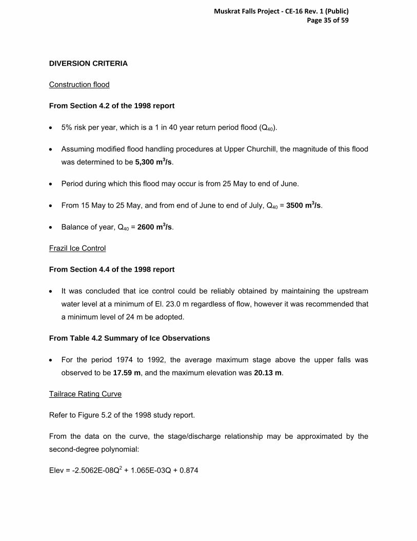
DIVERSION CRITERIA
Construction flood
From Section 4.2 of the 1998 report
• 5% risk per year, which is a 1 in 40 year return period flood (Q40).
• Assuming modified flood handling procedures at Upper Churchill, the magnitude of this flood
was determined to be 5,300 m3/s.
• Period during which this flood may occur is from 25 May to end of June.
• From 15 May to 25 May, and from end of June to end of July, Q40 = 3500 m3/s.
• Balance of year, Q40 = 2600 m3/s.
Frazil Ice Control
From Section 4.4 of the 1998 report
• It was concluded that ice control could be reliably obtained by maintaining the upstream
water level at a minimum of El. 23.0 m regardless of flow, however it was recommended that
a minimum level of 24 m be adopted.
From Table 4.2 Summary of Ice Observations
• For the period 1974 to 1992, the average maximum stage above the upper falls was
observed to be 17.59 m, and the maximum elevation was 20.13 m.
Tailrace Rating Curve
Refer to Figure 5.2 of the 1998 study report.
From the data on the curve, the stage/discharge relationship may be approximated by the
second-degree polynomial:
Elev = -2.5062E-08Q2 + 1.065E-03Q + 0.874
Muskrat Falls Project - CE-16 Rev. 1 (Public) Page 35 of 59
Rating Curve Upstream of Upper Falls
From LaSalle Ice Study:
• Elev = Q.429/3.6808 + 10.177
Spillway Flood Criteria
Maximum Design Flood
From Section 3.5 of Appendix B
• Use PMF
• Flood routing effect is negligible
• Spillway design flow (PMF) = 22,100 m3/s (1999 report).
• Maximum design flood level at PMF = 44 m
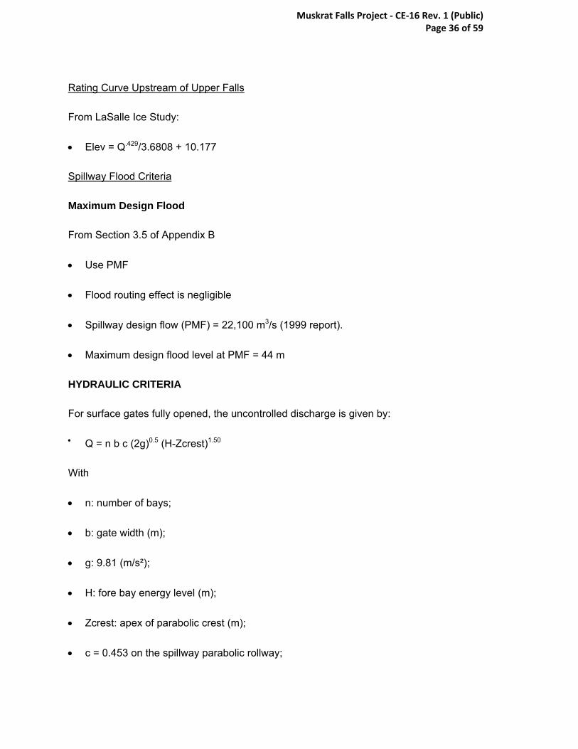
HYDRAULIC CRITERIA
For surface gates fully opened, the uncontrolled discharge is given by:
• Q = n b c (2g)0.5 (H-Zcrest)1.50
With
• n: number of bays;
• b: gate width (m);
• g: 9.81 (m/s²);
• H: fore bay energy level (m);
• Zcrest: apex of parabolic crest (m);
• c = 0.453 on the spillway parabolic rollway;
Muskrat Falls Project - CE-16 Rev. 1 (Public) Page 36 of 59

• c = 0.486 on the ogee crest of the north concrete dam;
• c = 0.429 on the deflated rubber dam with deflated crest El. 35.9 or 37.1 m;
• c = 0.35 on a broad or flat spillway crest at El. 5.0 m during the diversion phase;
• C = 0.50 for gate partially open.
For submerged vertical and/or radial gates fully opened with the vertical wall abutting both the
upstream stop logs and the submerged gate, the discharge is given by:
• Q = n b a c (2g)0.5 (H-Zsill)0.50
With
• n: number of bays;
• b: gate width (m);
• a: gate full opening (m);
• g: 9.81 (m/s²);
• H: fore bay energy level (m);
• Zsill: level of sill (5.0 m);
• c = 0.70.
For winter regulation with gates partly opened, the upstream fore bay level has been checked
with HECRAS.
Muskrat Falls Project - CE-16 Rev. 1 (Public) Page 37 of 59
Lower Churchill Project December 2007 Pre-Feed Engineering Study – Muskrat Falls MF1050 – Spillway Design Review Project No. 722850
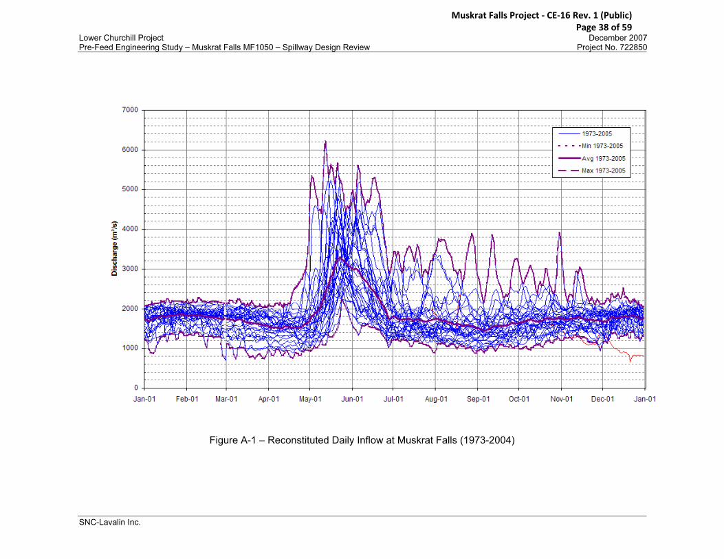
Figure A-1 – Reconstituted Daily Inflow at Muskrat Falls (1973-2004)
SNC-Lavalin Inc.
Muskrat Falls Project - CE-16 Rev. 1 (Public) Page 38 of 59

Muskrat Falls40 yr flood on Upper and Lower Churchill
with the modified flood handling procedures
0
1000
2000
3000
4000
5000
6000
25-Apr 05-May 15-May 25-May 04-Jun 14-Jun 24-Jun 04-Jul 14-Jul 24-Jul 03-Aug 13-Aug
Date
Dis
char
ge (m
³/s)
Local inflowOutflow from OssokPowerhouseJacopieTotal inflow
Figure A-2 – 40 Year Flood at Muskrat Falls
Muskrat Falls Project - CE-16 Rev. 1 (Public) Page 39 of 59

Spillway Stage DischargeNorth RCC Overflow Section
Crest Elevation at 39.5 mLength of Crest 430 m
0
262 79
3 1517 24
03 3434 45
97 5883 72
85 8795
38
39
40
41
42
43
44
45
46
0 500 1000 1500 2000 2500 3000 3500 4000 4500 5000 5500 6000 6500 7000 7500 8000 8500 9000 9500
discharge (m3/s)
Elev
atio
n (m
)
Figure A-3 – Fixed Crest Overflow Spillway Rating Curve for Scheme 3b
Muskrat Falls Project - CE-16 Rev. 1 (Public) Page 40 of 59

Figure A-4 – Station 03OE005 Between the Falls Stage Readings
Muskrat Falls Project - CE-16 Rev. 1 (Public) Page 41 of 59

Lower Churchill Project December 2007 Pre-Feed Engineering Study – Muskrat Falls MF1050 – Spillway Design Review Project No. 722850
SNC-Lavalin Inc.
Figure A-5 – Station 03OE004 Below Muskrat Falls Stage Readings
Muskrat Falls Project - CE-16 Rev. 1 (Public) Page 42 of 59

Figure A-6 – Diversion Rating Curve
Muskrat Falls Project - CE-16 Rev. 1 (Public) Page 43 of 59
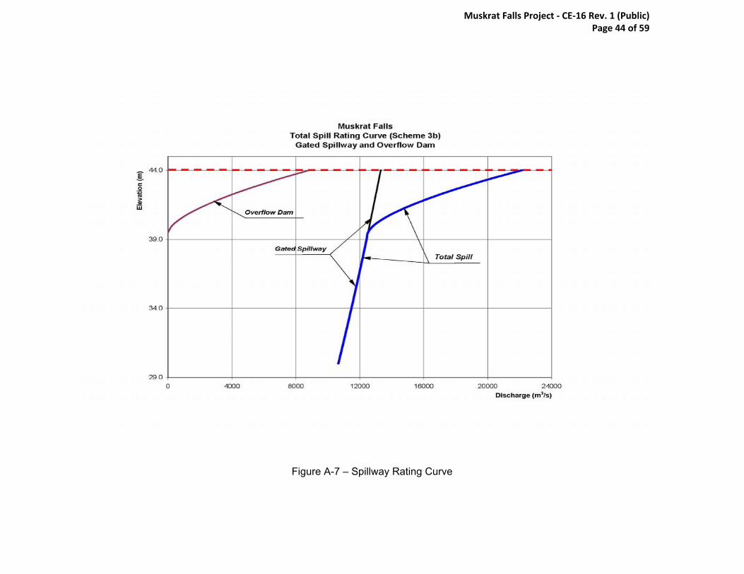
Figure A-7 – Spillway Rating Curve
Muskrat Falls Project - CE-16 Rev. 1 (Public) Page 44 of 59

Lower Churchill Project December 2007 Pre-Feed Engineering Study – Muskrat Falls MF1050 – Spillway Design Review Project No. 722850
SNC-Lavalin Inc.
APPENDIX B
COMPARATIVE COSTS
Muskrat Falls Project - CE-16 Rev. 1 (Public) Page 45 of 59
Lower Churchill Project December 2007 Pre-Feed Engineering Study – Muskrat Falls MF1050 – Spillway Design Review Project No. 722850
SNC-Lavalin Inc.
APPENDIX C
CONSTRUCTION SCHEDULE
Muskrat Falls Project - CE-16 Rev. 1 (Public) Page 46 of 59

Activity ID Activity Name
GeneralGeneralMilestonesMilestones
EngineeringEngineeringSite FacilitiesSite Facilities
Construction Construction Camp
Site AccessSite AccessTemporary SitTemporary Site Roads
SpillwaySpillwayGates & StoplGates & Stoplogs
IntakeIntakeTraskracks, BTraskracks, Bulkhead Gates & Service Gates
PowerhousePowerhouseTurbine GeneTurbine GeneratorOverhead CraOverhead CraneDraft Tube GaDraft Tube Gates
ProcurementProcurementSite FacilitiesSite Facilities
Construction Construction Camp
Site AccessSite AccessTemporary SitTemporary Site Roads
SpillwaySpillwayGates & StoplGates & Stoplogs
IntakeIntakeTraskracks, BTraskracks, Bulkhead Gates & Service Gates
PowerhousePowerhouseTurbine GeneTurbine GeneratorOverhead CraOverhead CraneDraft Tube GaDraft Tube Gates
ConstructionConstructionSite FacilitiesSite Facilities
Construction Construction Camp
Site AccessSite AccessPermanent SitPermanent Site RoadsTemporary SitTemporary Site RoadsTemporary BrTemporary Bridges
North SpurNorth SpurClearingClearingOverburden EOverburden ExcavationFillFillRelief WellsRelief WellsPump WellsPump Wells
CofferdamsCofferdamsUpstream CofUpstream CofferdamDownstream CDownstream Cofferdam
DamDamClearingClearingOverburden EOverburden ExcavationFoundationsFoundationsRCCRCCConcreteConcreteRubber DamRubber DamMiscellaneousMiscellaneous
SpillwaySpillwayClearingClearingOverburden EOverburden ExcavationRock ExcavatRock ExcavationLeft AbutmentLeft AbutmentPier 1Pier 1Pier 2Pier 2Right AbutmeRight AbutmentGravity SectioGravity Section
IntakeIntakeClearingClearingOverburden EOverburden ExcavationRock ExcavatRock ExcavationUnit 4Unit 4Unit 3Unit 3Unit 2Unit 2Unit 1Unit 1Gravity SectioGravity Section
PowerhousePowerhouseClearingClearingOverburden EOverburden ExcavationRock ExcavatRock ExcavationUnit 4Unit 4
Unit 3Unit 3
Unit 2Unit 2
Unit 1Unit 1
Erection BayErection Bay
SubstationSubstationSouth DamSouth Dam
1 2 3 4 5 6 7Year
Project Release Phase I Diversion Phase II DiversionFirst Power Full Commercial Power
Camp Operational
Pit Free Ready To Turn
Pit Free Ready To Turn
Pit Free Ready To Turn
Pit Free Ready To Turn
Muskrat Falls Hydroelectric Project
Variant 10 - Summary Schedule
22-Nov-07 10:14
Remaining WorkCritical Remaining Work
Milestone Page 1 of 1 Figure C2
Muskrat Falls Project - CE-16 Rev. 1 (Public) Page 47 of 59

APPENDIX D
VIEWS AND DRAWINGS
Muskrat Falls Project - CE-16 Rev. 1 (Public) Page 48 of 59

wer Churchill Project December 2007 eed Engineering Study – Muskrat Falls MF1050 – Spillway Design Review Project No. 722850
Figure D-1: Base Scheme 1a (3 Surface Vertical Gates 13.75 m Wide with a Rubber Dam) – Sheets 1/4
SNC-Lavalin Inc.
Muskrat Falls Project - CE-16 Rev. 1 (Public) Page 49 of 59

Figure D-1: Base Scheme 1a – Sheet 2/4
Muskrat Falls Project - CE-16 Rev. 1 (Public) Page 50 of 59

Figure D-1: Base Scheme 1a – Sheet 3/4
Muskrat Falls Project - CE-16 Rev. 1 (Public) Page 51 of 59

Figure D-1: Base Scheme 1a – Sheet 4/4
Muskrat Falls Project - CE-16 Rev. 1 (Public) Page 52 of 59

Figure D-2: Scheme 1f (5 Surface Vertical Gates 13.75 m Wide and No Rubber Dam)
Muskrat Falls Project - CE-16 Rev. 1 (Public) Page 53 of 59

Figure D-3: Scheme 3b (4 Submerged Radial Gates 12.5 m Wide and No Rubber Dam) Sheet 1/3
Muskrat Falls Project - CE-16 Rev. 1 (Public) Page 54 of 59

Figure D-3: Scheme 3b (4 Submerged Radial Gates 12.5 m Wide and No Rubber Dam) – Sheet 2/3
Muskrat Falls Project - CE-16 Rev. 1 (Public) Page 55 of 59

Lower Churchill Project December 2007 Pre-Feed Engineering Study – Muskrat Falls MF1050 – Spillway Design Review Project No. 722850
Figure D-3: Scheme 3b (4 Submerged Radial Gates 12.5 m Wide and No Rubber Dam) – Sheet 3/3
SNC-Lavalin Inc.
Muskrat Falls Project - CE-16 Rev. 1 (Public) Page 56 of 59

Muskrat Falls Project - CE-16 Rev. 1 (Public) Page 57 of 59

Muskrat Falls Project - CE-16 Rev. 1 (Public) Page 58 of 59

www.snclavalin.com
SNC-LAVALIN Inc. 1133 Topsail Road Mount Pearl, NL A1N 5G2 Canada Tel.: (709) 368-0118 Fax: (709) 368-3541
Muskrat Falls Project - CE-16 Rev. 1 (Public) Page 59 of 59