Embed Size (px)
Citation preview
Quanta Computer Inc. Report No.: 20130222-1
Page 1 of 60
CE EMC TEST REPORT
For
Laptop Computer
Brand Name: OLPC Model NO.: XO-4 HS / XO-4 / XO-4 HS Touch / XO-4 Touch Report NO.: 20130222-1 Issued Date: Feb. 22, 2013 Issued By: Compliance Laboratory of Tech-Front (Shanghai) Computer
Co., Ltd Lab Address: No. 68, Sanzhuang Road, Songjiang Export Processing Zone,
Shanghai, P. R. China Tel: +86-21-3781-8168 Fax: +86-21-6774-7135
The test result relate only to the samples tested. The test report shall not be reproduced except in full without the written approval of our laboratory. This report must not be used to claim product endorsement by CNAS or any agency of the Government. The test results shown in the test report are traceable to the national/international standard through the calibration of the equipment and evaluated measurement uncertainty herein.
Quanta Computer Inc. Report No.: 20130222-1
Page 2 of 60
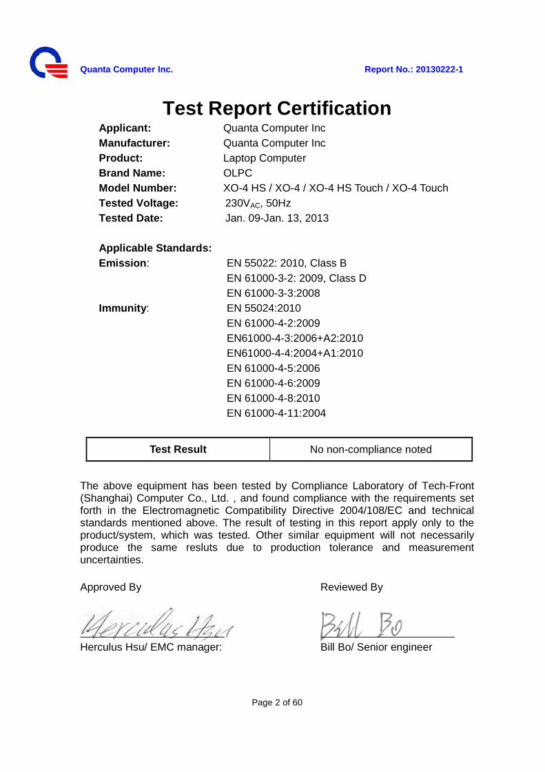
Test Report Certification Applicant: Quanta Computer Inc Manufacturer: Quanta Computer Inc Product: Laptop Computer Brand Name: OLPC Model Number: XO-4 HS / XO-4 / XO-4 HS Touch / XO-4 Touch Tested Voltage: 230VAC, 50Hz Tested Date: Jan. 09-Jan. 13, 2013
Applicable Standards: Emission: EN 55022: 2010, Class B
EN 61000-3-2: 2009, Class D EN 61000-3-3:2008
Immunity: EN 55024:2010 EN 61000-4-2:2009 EN61000-4-3:2006+A2:2010 EN61000-4-4:2004+A1:2010 EN 61000-4-5:2006 EN 61000-4-6:2009 EN 61000-4-8:2010 EN 61000-4-11:2004
Test Result No non-compliance noted
The above equipment has been tested by Compliance Laboratory of Tech-Front (Shanghai) Computer Co., Ltd. , and found compliance with the requirements set forth in the Electromagnetic Compatibility Directive 2004/108/EC and technical standards mentioned above. The result of testing in this report apply only to the product/system, which was tested. Other similar equipment will not necessarily produce the same resluts due to production tolerance and measurement uncertainties. Approved By Reviewed By Herculus Hsu/ EMC manager: Bill Bo/ Senior engineer
Quanta Computer Inc. Report No.: 20130222-1
Page 3 of 60
Section 1: General Information…………………………….……....……… 6 1.1 Test result summary …………………...………………………….………6 1.2 Introduction …………………………………………………………...…………7
1.3 Test Procedure ……………………………………….………………………..8
Section 2: Test Facility and Procedure………………………………..….9 2.1 Test Facility used for Emission Testing ………………………..……. .9
2.1.1 Measurement Uncertainty …………………………………………..……. .9 2.1.2 Lab Accreditation ……………………………..…………..…….……..….…10 2.1.3 Software to exercise EUT ……………………………………………….…10 2.1.4 Special Accessories …………………….……………………………….….10 2.1.5 Equipment Modifications and Deviations ………………………………...10 2.1.6 Test Configuration …………………………..……………………..……….11 - Arrangement block diagram ……………………………………..……..…. 11 - Associated equipment ……………..……………………………..………... 11 - Pre-test configuration ……………..………………………………..……….13 - Worst case for final testing ………………………………………..………. 13
2.1.7 Cable Description and Information ………………………….……………13
2.2 Measurement Equipment ……………….………………………..……. 14 2.2.1 Conducted Emissions ……………………………………………………..14 2.2.2 Radiated Emissions …………..……………………………………………14 2.2.3 Power Harmonic / Flickers …………………………………………………15 2.2.4 Electrostatic Discharge (ESD) Immunity …………...…………..…….…..15 2.2.5 Radiated Electromagnetic Field Immunity ………….…………..…….….15 2.2.6 Fast Transient / Burst Immunity ……………………..……………………16 2.2.7 Surge Immunity …………………………..………………………..…….….16 2.2.8 Conducted Disturbance / Induced Radio-Frequency Field Immunity ...16 2.2.9 Power Frequency Magnetic Field Immunity ………………………….….17 2.2.10 Voltage Dips / Short Interruptions and Interruptions ……….………….17
Quanta Computer Inc. Report No.: 20130222-1
Page 4 of 60
Section 3: Electromagnetic Emissions Test……………………………. 18 3.1 Emission ……….………………………………………………………………. 18
3.1.1 Line Conducted Emissions Test ………………………………………..…. 18 - Measurement Procedures Utilized for Conducted Emissions ……..………. 18 - Limits ……………………………………….………...………………….………. 19 - Test setup………….…………………………………………………….………. 20 - Conducted Emissions Test Data …………………………………….…..……. 21
3.1.2 Radiated Emissions Test ………………………………………………...… 23 - Measurement Procedures Utilized for Radiated Emissions …………..……. 23 - Limits ……………………………………….……………………………………. 24 - Test setup………….…………………………………………………….………. 24 - Radiated Emissions Test Data ……………………………………….………. 26
3.1.3 Power Harmonics Measurement ……………………………………….… 30 - Measurement Procedures Utilized for Harmonics…………………….……. 30 - Test setup……………………….…………………………………….………. 31 - Test Condition…………….……………………………………………….……. 31 - Test results…………………………………………………………….………. 31
3.1.4 Power Voltage Fluctuation / Flicker Measurement ………………………32 - Measurement Procedures Utilized for Flicker……….…………….………. 32 - Test setup…………………..………………………………………….………. 32 - Test Condition………………………………………………………….………. 33 - Test results…………………………………………………………….………. 33
3.2 Electromagnetic Immunity Report ……………………….......…………34 3.2.1 Electrostatic Discharge (ESD) Immunity Test …………….………………36 - Measurement Procedures Utilized for ESD………………………….………. 36 - Test setup……………………………………………………………….………. 37 - Test Condition………………………………………………………….………. 37 - Test results………………………………………………………………….…… 38
3.2.2 Radiated Electromagnetic Field Immunity Test ………….…….…………39 - Measurement Procedures Utilized for RS.……..…….……………….……. 39 - Test setup……………………………………………………………….………. 39 - Test Condition………………………………………………………….………. 40 - Test results…………………………………………………………….………. 40
3.2.3 Fast Transient/Burst Immunity Test……………………...…………………41 - Measurement Procedures Utilized for EFT………………………….………. 41 - Test setup………………………………………………………………………. 41 - Test Condition………………………………………………………….………. 42 - Test results…………………………………………………………….………. 42
Quanta Computer Inc. Report No.: 20130222-1
Page 5 of 60
3.2.4 Surge Immunity Test ………...…………………………………………… 43 - Measurement Procedures Utilized for Surge……………………….………. 43 - Test setup……………………………………………………………….………. 43 - Test Condition………………………………………………………….………. 44 - Test results…………………………………………………………….………. 44
3.2.5 Conducted Disturbance / Induced Radio-Frequency Field Immunity Test - Measurement Procedures Utilized for CS.………………………….………. 45 - Test setup……………………………………………………………….………. 45 - Test Condition………………………………………………………….………. 46 - Test results…………………………………………………………….………. 46
3.2.6 Power Frequency Magnetic Field Immunity Test ……………...........… 47 - Measurement Procedures Utilized for PFMF.……………………..……….… 47 - Test setup……………………………………………………………….………. 47 - Test Condition…………………………………………………………...………. 48 - Test results…………………………………………………………….…...……. 48
3.2.7 Voltage Dips / Short Interruptions and Interruptions Test ………….…… 49 - Measurement Procedures Utilized for Dips………………………….………. 49 - Test setup……………………………………………………………….………. 49 - Test Condition………………………………………………………….………. 50 - Test results…………………………………………………………….………. 50
Section 4: Test Arrangement Photos………………………..………………51 4.1 Conducted Emissions …………………...……………………………………51 4.2 Radiated Emissions ……………………..…………………….……………52 4.3 Power Harmonics and Flick Measurement ………...…………………….. 54 4.4 Electrostatic Discharge (ESD)…………………….……...……..………... 55 4.5 Radiated Electromagnetic Field Immunity………………..…………….... 58 4.6 Fast Transient / Burst Immunity……………………….….………..………58 4.7 Surge Immunity………………………………………………….……….…. 59 4.8 Conducted Disturbance, Induced Radio-Frequency Field Immunity…..…59 4.9 Power Frequency Magnetic Field Immunity Test ……………………...…. 60 4.10 Voltage Dips / Short Interruptions and Interruptions……………………. 60
Quanta Computer Inc. Report No.: 20130222-1
Page 6 of 60
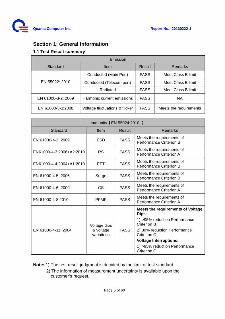
Section 1: General Information 1.1 Test Result summary
Emission
Standard Item Result Remarks
EN 55022: 2010
Conducted (Main Port) PASS Meet Class B limit
Conducted (Telecom port) PASS Meet Class B limit
Radiated PASS Meet Class B limit
EN 61000-3-2: 2009 Harmonic current emissions PASS NA
EN 61000-3-3:2008 Voltage fluctuations & flicker PASS Meets the requirements
Immunity【EN 55024:2010 】
Standard Item Result Remarks
EN 61000-4-2: 2009 ESD PASS Meets the requirements of Performance Criterion B
EN61000-4-3:2006+A2:2010 RS PASS Meets the requirements of Performance Criterion A
EN61000-4-4:2004+A1:2010 EFT PASS Meets the requirements of Performance Criterion B
EN 61000-4-5: 2006 Surge PASS Meets the requirements of Performance Criterion B
EN 61000-4-6: 2009 CS PASS Meets the requirements of Performance Criterion A
EN 61000-4-8:2010 PFMF PASS Meets the requirements of Performance Criterion A
EN 61000-4-11: 2004 Voltage dips
& voltage variations
PASS
Meets the requirements of Voltage Dips: 1) >95% reduction Performance Criterion B 2) 30% reduction Performance Criterion C Voltage Interruptions: 1) >95% reduction Performance Criterion C.
Note: 1) The test result judgment is decided by the limit of test standard
2) The information of measurement uncertainty is available upon the customer’s request.
Quanta Computer Inc. Report No.: 20130222-1
Page 7 of 60
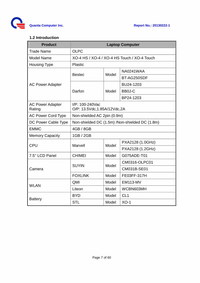
1.2 Introduction
Product Laptop Computer
Trade Name OLPC
Model Name XO-4 HS / XO-4 / XO-4 HS Touch / XO-4 Touch
Housing Type Plastic
AC Power Adapter
Bestec Model NA0241WAA
BT-AG250SDF
Darfon Model
BU24-1203
BB0J-C
BP24-1203
AC Power Adapter Rating
I/P: 100-240Vac O/P: 13.5Vdc,1.85A/12Vdc,2A
AC Power Cord Type Non-shielded AC 2pin (0.9m)
DC Power Cable Type Non-shielded DC (1.5m) /Non-shielded DC (1.8m)
EMMC 4GB / 8GB
Memory Capacity 1GB / 2GB
CPU Marvell Model PXA2128 (1.0GHz)
PXA2128 (1.2GHz)
7.5’’ LCD Panel CHIMEI Model G075ADE-T01
Camera SUYIN Model
CM0316-OLPC01
CM031B-SE01
FOXLINK Model FE03FF-317H
WLAN QMI Model EM113-MV
Liteon Model WCBN603MH
Battery BYD Model CL1
STL Model XO-1
Quanta Computer Inc. Report No.: 20130222-1
Page 8 of 60
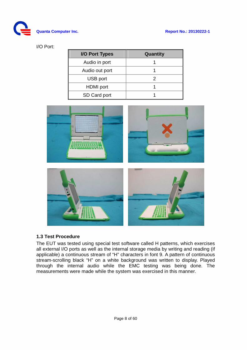
I/O Port:
I/O Port Types Quantity
Audio in port 1
Audio out port 1
USB port 2
HDMI port 1
SD Card port 1
1.3 Test Procedure The EUT was tested using special test software called H patterns, which exercises all external I/O ports as well as the internal storage media by writing and reading (if applicable) a continuous stream of “H” characters in font 9. A pattern of continuous stream-scrolling black “H” on a white background was written to display. Played through the internal audio while the EMC testing was being done. The measurements were made while the system was exercised in this manner.
Quanta Computer Inc. Report No.: 20130222-1
Page 9 of 60
Section 2: Test Facility and Procedure 2.1 Test Facility Used for Emission Testing Conducted Emissions Facilities: Conducted Emissions were performed at Compliance Laboratory of Tech - Front (Shanghai) Computer Co, Ltd of No.68 Sanzhuang Road, Songjiang Export Processing Zone, Shanghai, P. R. China FCC Registration No. 602285 VCCI Registration No. C-2529/ T-1836 Radiated Emissions Facilities: Radiated Emissions measurements were performed at Compliance Laboratory of Tech-Front (Shanghai) Computer Co., Ltd. of No.68 Sanzhuang Road, Songjiang Export Processing Zone, Shanghai, P. R. China FCC Registration No. 602285 VCCI Registration No. R-2319 (10m Chamber)/ G-191 (10m Chamber) / R-3341 (3m-2Chamber) / G-209 (3m-2 Chamber) /R-2320 (3m Chamber site 1) Note: “R-”to represent bellows 1GHz, “G-”to represent above 1GHz. 2.1.1 Measurement Uncertainty The measurement uncertainty has been determined to be the following: AC Conducted Emissions = 3.2 dB Telecom Conducted Emissions = 3.5 dB Radiated Emissions (30MHz~1000MHz) = 4.1 dB Radiated Emissions (1000MHz~18000MHz) = 4.6 dB The equipment conforms to the requirement of CISPR 16-1, CISPR 16-4-2, ANSI C63.2 and other required standards. Calibration of all test and measurement, including any accessories that may effect such calibration, is checked frequently to ensure the accuracy. Adjustments are made and correction factors are applied in accordance with the instructions contained in the respective manual.
Quanta Computer Inc. Report No.: 20130222-1
Page 10 of 60
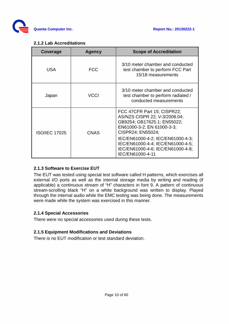
2.1.2 Lab Accreditations
Coverage Agency Scope of Accreditation
USA FCC 3/10 meter chamber and conducted test chamber to perform FCC Part
15/18 measurements
Japan VCCI 3/10 meter chamber and conducted test chamber to perform radiated /
conducted measurements
ISO/IEC 17025 CNAS
FCC 47CFR Part 15; CISPR22; AS/NZS CISPR 22; V-3/2008.04; GB9254; GB17625.1; EN55022; EN61000-3-2; EN 61000-3-3; CISPR24; EN55024; IEC/EN61000-4-2; IEC/EN61000-4-3; IEC/EN61000-4-4; IEC/EN61000-4-5; IEC/EN61000-4-6; IEC/EN61000-4-8; IEC/EN61000-4-11
2.1.3 Software to Exercise EUT The EUT was tested using special test software called H patterns, which exercises all external I/O ports as well as the internal storage media by writing and reading (if applicable) a continuous stream of “H” characters in font 9. A pattern of continuous stream-scrolling black “H” on a white background was written to display. Played through the internal audio while the EMC testing was being done. The measurements were made while the system was exercised in this manner. 2.1.4 Special Accessories There were no special accessories used during these tests. 2.1.5 Equipment Modifications and Deviations There is no EUT modification or test standard deviation.
Quanta Computer Inc. Report No.: 20130222-1
Page 11 of 60
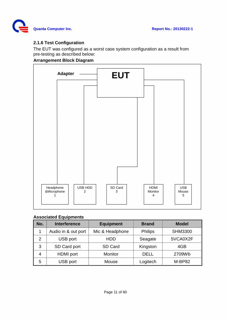
2.1.6 Test Configuration The EUT was configured as a worst case system configuration as a result from pre-testing as described below: Arrangement Block Diagram
Associated Equipments
No. Interference Equipment Brand Model
1 Audio in & out port Mic & Headphone Philips SHM3300
2 USB port HDD Seagate 5VCA0X2F
3 SD Card port SD Card Kingston 4GB
4 HDMI port Monitor DELL 2709Wb
5 USB port Mouse Logitech M-BP82
EUT
Headphone &Microphone
1
USB HDD 2
USB Mouse
5
HDMI Monitor
4
Adapter
SD Card 3

Quanta Computer Inc. Report No.: 20130222-1
Page 12 of 60
Pre-test configuration
Prior to taking the formal emissions data collected in this report many hours of pre-testing have been performed. The selection of the worst case system documented in this report was based upon this pre-testing.
Mode CPU LCD Panel Memory EMMC WLAN Camera Battery Adapter
1 Marvell
PXA2128 (1.0GHz)
CHIMEI G075ADE-T01
1GB 4GB QMI EM113-MV
SUYIN CM031B-SE01
BYD CL1 Bestec NA0241WAA
2 Marvell
PXA2128 (1.2GHz)
CHIMEI G075ADE-T01 2GB 8GB
Liteon WCBN603M
H
SUYIN CM0316-OLPC0
1 BYD CL1 Bastec
BT-AG250SDF
3 Marvell
PXA2128 (1.0GHz)
CHIMEI G075ADE-T01 2GB 4GB
QMI EM113-MV
FOXLINK FE03FF-317H STL XO-1
Darfon BU24-1203
4 Marvell
PXA2128 (1.2GHz)
CHIMEI G075ADE-T01 1GB 4GB
Liteon WCBN603M
H
SUYIN CM0316-OLPC0
1 STL XO-1 Darfon BB0J-C
5 Marvell
PXA2128 (1.0GHz)
CHIMEI G075ADE-T01 2GB 8GB QMI
EM113-MV SUYIN
CM031B-SE01 BYD CL1 Bastec BT-AG250SDF
6 Marvell
PXA2128 (1.0Hz)
CHIMEI G075ADE-T01
1GB 8GB Liteon
WCBN603MH
FOXLINK FE03FF-317H
BYD CL1 Darfon BU24-1203
7 Marvell
PXA2128 (1.0GHz)
CHIMEI G075ADE-T01
1GB 4GB QMI EM113-MV
SUYIN CM031B-SE01
STL XO-1 Darfon BP24-1203
8 Marvell
PXA2128 (1.2GHz)
CHIMEI G075ADE-T01 1GB 8GB
Liteon WCBN603M
H
FOXLINK FE03FF-317H BYD CL1
Bastec NA0241WAA
9 Marvell
PXA2128 (1.0GHz)
CHIMEI G075ADE-T01 1GB 4GB
QMI EM113-MV
SUYIN CM0316-OLPC0
1 STL XO-1
Bastec NA0241WAA
10 Marvell
PXA2128 (1.2GHz)
CHIMEI G075ADE-T01 2GB 4GB
Liteon WCBN603M
H
SUYIN CM031B-SE01 BYD CL1
Darfon BP24-1203
Quanta Computer Inc. Report No.: 20130222-1
Page 13 of 60
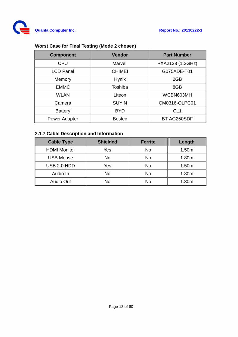
Worst Case for Final Testing (Mode 2 chosen)
Component Vendor Part Number
CPU Marvell PXA2128 (1.2GHz)
LCD Panel CHIMEI G075ADE-T01
Memory Hynix 2GB
EMMC Toshiba 8GB
WLAN Liteon WCBN603MH
Camera SUYIN CM0316-OLPC01
Battery BYD CL1
Power Adapter Bestec BT-AG250SDF
2.1.7 Cable Description and Information
Cable Type Shielded Ferrite Length
HDMI Monitor Yes No 1.50m
USB Mouse No No 1.80m
USB 2.0 HDD Yes No 1.50m
Audio In No No 1.80m
Audio Out No No 1.80m
Quanta Computer Inc. Report No.: 20130222-1
Page 14 of 60
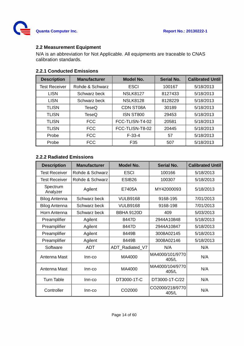
2.2 Measurement Equipment N/A is an abbreviation for Not Applicable. All equipments are traceable to CNAS calibration standards.
2.2.1 Conducted Emissions
Description Manufacturer Model No. Serial No. Calibrated Until
Test Receiver Rohde & Schwarz ESCI 100167 5/18/2013
LISN Schwarz beck NSLK8127 8127433 5/18/2013
LISN Schwarz beck NSLK8128 8128229 5/18/2013
TLISN TeseQ CDN ST08A 30189 5/18/2013
TLISN TeseQ ISN ST800 29453 5/18/2013
TLISN FCC FCC-TLISN-T4-02 20581 5/18/2013
TLISN FCC FCC-TLISN-T8-02 20445 5/18/2013
Probe FCC F-33-4 57 5/18/2013
Probe FCC F35 507 5/18/2013
2.2.2 Radiated Emissions
Description Manufacturer Model No. Serial No. Calibrated Until
Test Receiver Rohde & Schwarz ESCI 100166 5/18/2013
Test Receiver Rohde & Schwarz ESIB26 100307 5/18/2013
Spectrum Analyzer
Agilent E7405A MY42000093 5/18/2013
Bilog Antenna Schwarz beck VULB9168 9168-195 7/01/2013
Bilog Antenna Schwarz beck VULB9168 9168-198 7/01/2013
Horn Antenna Schwarz beck BBHA 9120D 409 5/03/2013
Preamplifier Agilent 8447D 2944A10848 5/18/2013
Preamplifier Agilent 8447D 2944A10847 5/18/2013
Preamplifier Agilent 8449B 3008A02145 5/18/2013
Preamplifier Agilent 8449B 3008A02146 5/18/2013
Software ADT ADT_Radiated_V7 N/A N/A
Antenna Mast Inn-co MA4000 MA4000/101/9770405/L
N/A
Antenna Mast Inn-co MA4000 MA4000/104/9770405/L
N/A
Turn Table Inn-co DT3000-1T-C DT3000-1T-C/22 N/A
Controller Inn-co CO2000 CO2000/218/9770405/L
N/A
Quanta Computer Inc. Report No.: 20130222-1
Page 15 of 60
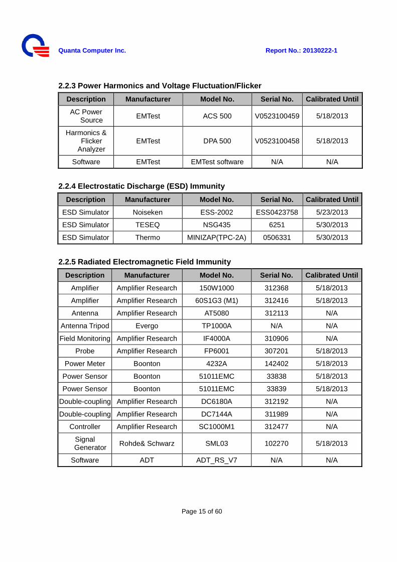
2.2.3 Power Harmonics and Voltage Fluctuation/Flicker
Description Manufacturer Model No. Serial No. Calibrated Until
AC Power Source EMTest ACS 500 V0523100459 5/18/2013
Harmonics & Flicker
Analyzer EMTest DPA 500 V0523100458 5/18/2013
Software EMTest EMTest software N/A N/A
2.2.4 Electrostatic Discharge (ESD) Immunity
Description Manufacturer Model No. Serial No. Calibrated Until
ESD Simulator Noiseken ESS-2002 ESS0423758 5/23/2013
ESD Simulator TESEQ NSG435 6251 5/30/2013
ESD Simulator Thermo MINIZAP(TPC-2A) 0506331 5/30/2013
2.2.5 Radiated Electromagnetic Field Immunity
Description Manufacturer Model No. Serial No. Calibrated Until
Amplifier Amplifier Research 150W1000 312368 5/18/2013
Amplifier Amplifier Research 60S1G3 (M1) 312416 5/18/2013
Antenna Amplifier Research AT5080 312113 N/A
Antenna Tripod Evergo TP1000A N/A N/A
Field Monitoring Amplifier Research IF4000A 310906 N/A
Probe Amplifier Research FP6001 307201 5/18/2013
Power Meter Boonton 4232A 142402 5/18/2013
Power Sensor Boonton 51011EMC 33838 5/18/2013
Power Sensor Boonton 51011EMC 33839 5/18/2013
Double-coupling Amplifier Research DC6180A 312192 N/A
Double-coupling Amplifier Research DC7144A 311989 N/A
Controller Amplifier Research SC1000M1 312477 N/A
Signal Generator Rohde& Schwarz SML03 102270 5/18/2013
Software ADT ADT_RS_V7 N/A N/A
Quanta Computer Inc. Report No.: 20130222-1
Page 16 of 60
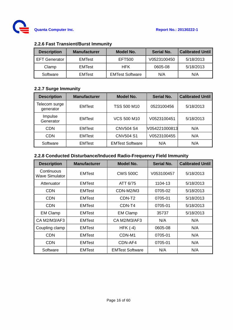
2.2.6 Fast Transient/Burst Immunity
Description Manufacturer Model No. Serial No. Calibrated Until
EFT Generator EMTest EFT500 V0523100450 5/18/2013
Clamp EMTest HFK 0605-08 5/18/2013
Software EMTest EMTest Software N/A N/A
2.2.7 Surge Immunity
Description Manufacturer Model No. Serial No. Calibrated Until
Telecom surge generator
EMTest TSS 500 M10 0523100456 5/18/2013
Impulse Generator EMTest VCS 500 M10 V0523100451 5/18/2013
CDN EMTest CNV504 S4 V054221000813 N/A
CDN EMTest CNV504 S1 V0523100455 N/A
Software EMTest EMTest Software N/A N/A
2.2.8 Conducted Disturbance/Induced Radio-Frequency Field Immunity
Description Manufacturer Model No. Serial No. Calibrated Until
Continuous Wave Simulator
EMTest CWS 500C V053100457 5/18/2013
Attenuator EMTest ATT 6/75 1104-13 5/18/2013
CDN EMTest CDN-M2/M3 0705-02 5/18/2013
CDN EMTest CDN-T2 0705-01 5/18/2013
CDN EMTest CDN-T4 0705-01 5/18/2013
EM Clamp EMTest EM Clamp 35737 5/18/2013
CA M2/M3/AF3 EMTest CA M2/M3/AF3 N/A N/A
Coupling clamp EMTest HFK (-4) 0605-08 N/A
CDN EMTest CDN-M1 0705-01 N/A
CDN EMTest CDN-AF4 0705-01 N/A
Software EMTest EMTest Software N/A N/A
Quanta Computer Inc. Report No.: 20130222-1
Page 17 of 60
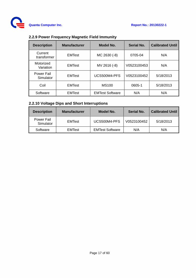
2.2.9 Power Frequency Magnetic Field Immunity
Description Manufacturer Model No. Serial No. Calibrated Until
Current transformer EMTest MC 2630 (-8) 0705-04 N/A
Motorized Variation EMTest MV 2616 (-8) V0523100453 N/A
Power Fail Simulator EMTest UCS500M4-PFS V0523100452 5/18/2013
Coil EMTest MS100 0605-1 5/18/2013
Software EMTest EMTest Software N/A N/A
2.2.10 Voltage Dips and Short Interruptions
Description Manufacturer Model No. Serial No. Calibrated Until
Power Fail Simulator
EMTest UCS500M4-PFS V0523100452 5/18/2013
Software EMTest EMTest Software N/A N/A
Quanta Computer Inc. Report No.: 20130222-1
Page 18 of 60
Section3: Electromagnetic Emissions Test 3.1 Emission 3.1.1 Line Conducted Emissions Test - Measurement Procedures Utilized for Conducted Emissions The EUT was set up as per the test configuration to simulate typical usage per the user’s manual. When the EUT is a tabletop system, a wooden table with a height of 0.8 meters is used and is placed on the ground plane as per EN 55022. Associated equipment, if needed, was placed as per EN 55022. All I/O cables were positioned to simulate typical actual usage as per EN 55022. The test equipment EUT installed received AC power through a Line Impedance Stabilization Network (LISN), which supplied power source and was grounded to the ground plane. All associated equipment received power from a second LISN. For conducted emission test on telecommunication ports, a telecommunication port is connected by its signal cable to an impedance stabilization network (ISN). During the testing, the LAN utilization is in excess of 10 % and sustains that level for a minimum of 250 ms. the traffic rate is monitored by the program of Net Speed. The EUT test program was started. Emissions were measured on each current carrying line of the EUT using an EMI Test Receiver connected to the LISN powering the EUT. The Receiver scanned from 150 KHz to 30MHz for emissions in each of the test modes. During the above scans under battery charging mode, the emissions were maximized by cable manipulation. The EUT configuration and cable configuration of the above highest emission level were recorded for reference of the final test.
Quanta Computer Inc. Report No.: 20130222-1
Page 19 of 60
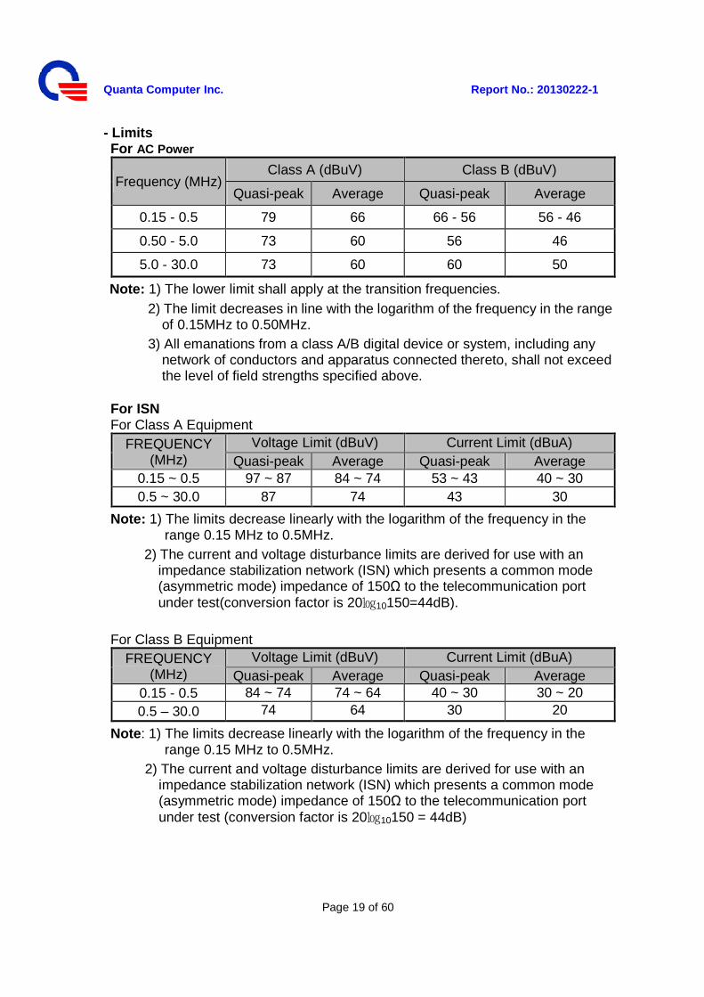
- Limits For AC Power
Frequency (MHz) Class A (dBuV) Class B (dBuV)
Quasi-peak Average Quasi-peak Average
0.15 - 0.5 79 66 66 - 56 56 - 46
0.50 - 5.0 73 60 56 46
5.0 - 30.0 73 60 60 50
Note: 1) The lower limit shall apply at the transition frequencies. 2) The limit decreases in line with the logarithm of the frequency in the range
of 0.15MHz to 0.50MHz. 3) All emanations from a class A/B digital device or system, including any
network of conductors and apparatus connected thereto, shall not exceed the level of field strengths specified above.
For ISN For Class A Equipment
FREQUENCY (MHz)
Voltage Limit (dBuV) Current Limit (dBuA) Quasi-peak Average Quasi-peak Average
0.15 ~ 0.5 97 ~ 87 84 ~ 74 53 ~ 43 40 ~ 30 0.5 ~ 30.0 87 74 43 30
Note: 1) The limits decrease linearly with the logarithm of the frequency in the range 0.15 MHz to 0.5MHz.
2) The current and voltage disturbance limits are derived for use with an impedance stabilization network (ISN) which presents a common mode (asymmetric mode) impedance of 150Ω to the telecommunication port under test(conversion factor is 2010150=44dB).
For Class B Equipment
FREQUENCY (MHz)
Voltage Limit (dBuV) Current Limit (dBuA) Quasi-peak Average Quasi-peak Average
0.15 - 0.5 84 ~ 74 74 ~ 64 40 ~ 30 30 ~ 20 0.5 – 30.0 74 64 30 20
Note: 1) The limits decrease linearly with the logarithm of the frequency in the range 0.15 MHz to 0.5MHz.
2) The current and voltage disturbance limits are derived for use with an impedance stabilization network (ISN) which presents a common mode (asymmetric mode) impedance of 150Ω to the telecommunication port under test (conversion factor is 2010150 = 44dB)
Quanta Computer Inc. Report No.: 20130222-1
Page 20 of 60
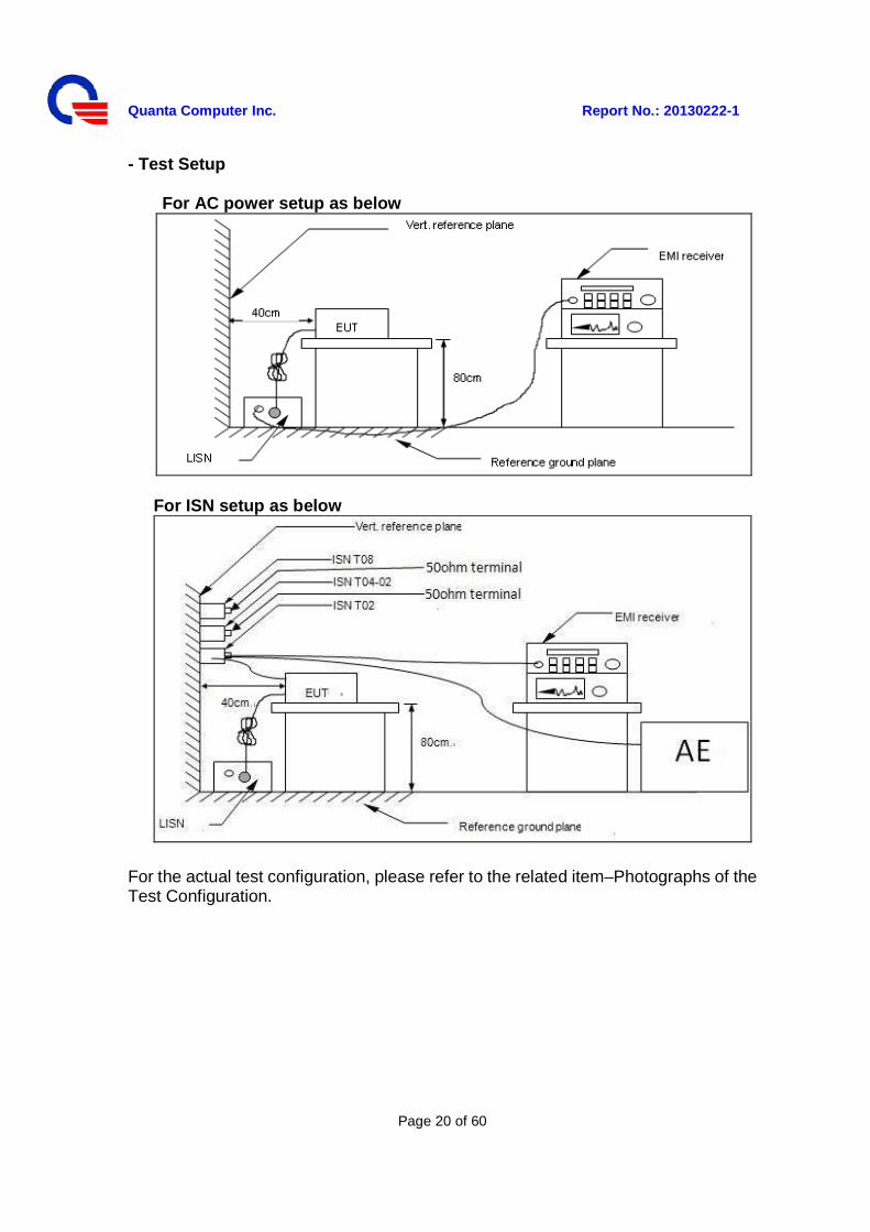
- Test Setup For AC power setup as below
For ISN setup as below
For the actual test configuration, please refer to the related item–Photographs of the Test Configuration.
Quanta Computer Inc. Report No.: 20130222-1
Page 21 of 60
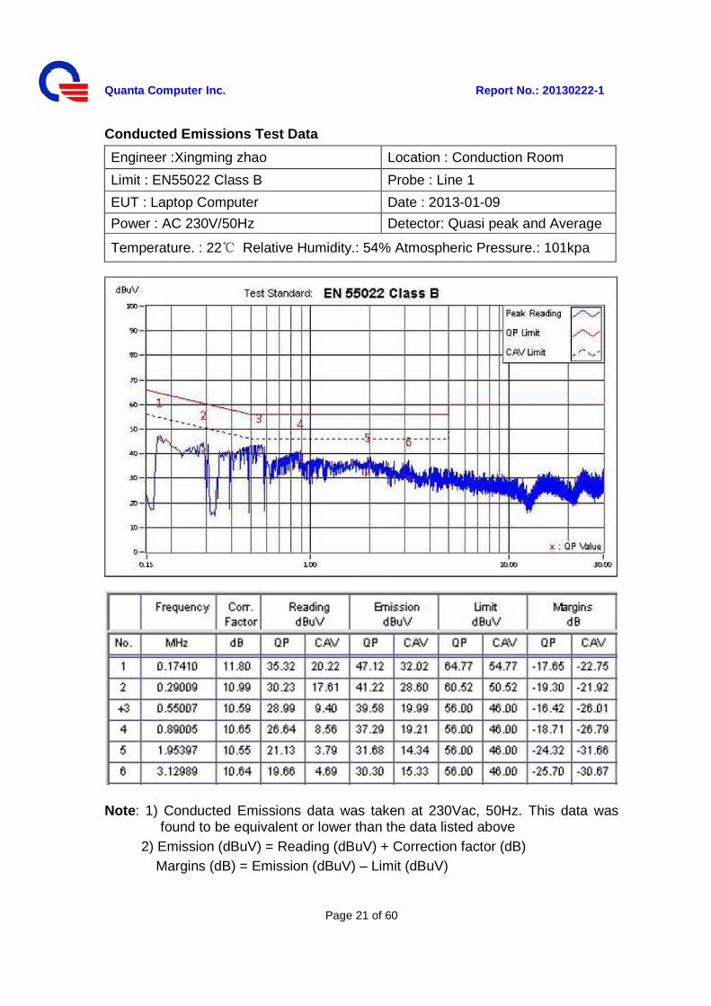
Conducted Emissions Test Data
Engineer :Xingming zhao Location : Conduction Room
Limit : EN55022 Class B Probe : Line 1
EUT : Laptop Computer Date : 2013-01-09
Power : AC 230V/50Hz Detector: Quasi peak and Average
Temperature. : 22 Relative Humidity.: 54% Atmospheric Pressure.: 101kpa
Note: 1) Conducted Emissions data was taken at 230Vac, 50Hz. This data was found to be equivalent or lower than the data listed above
2) Emission (dBuV) = Reading (dBuV) + Correction factor (dB) Margins (dB) = Emission (dBuV) – Limit (dBuV)
Quanta Computer Inc. Report No.: 20130222-1
Page 22 of 60
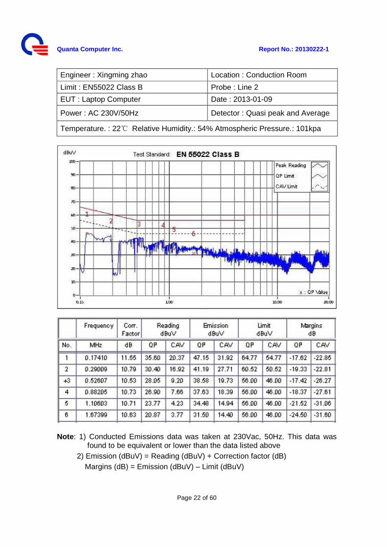
Engineer : Xingming zhao Location : Conduction Room
Limit : EN55022 Class B Probe : Line 2
EUT : Laptop Computer Date : 2013-01-09
Power : AC 230V/50Hz Detector : Quasi peak and Average
Temperature. : 22 Relative Humidity.: 54% Atmospheric Pressure.: 101kpa
Note: 1) Conducted Emissions data was taken at 230Vac, 50Hz. This data was found to be equivalent or lower than the data listed above
2) Emission (dBuV) = Reading (dBuV) + Correction factor (dB) Margins (dB) = Emission (dBuV) – Limit (dBuV)
Quanta Computer Inc. Report No.: 20130222-1
Page 23 of 60
3.1.2 Radiated Emissions Test - Measurement Procedures Utilized for Radiated Emissions The equipment was set up as per the test configuration to simulate typical usage per the user’s manual. When the EUT is a tabletop system, a wooden turntable with a height of 0.8 meters is used which is placed on the ground plane. Associated equipment, if needed, was placed as per EN 55022. All I/O cables were positioned to simulate typical usage as per EN 55022. The EUT received AC power source, from the outlet socket under the turntable. All associated equipment received power from another socket under the turntable. Mains cables, telephone lines or other connections to auxiliary equipment located outside the test are shall drape to the floor. No extension cords shall be used to mains receptacle. The antenna was placed at 10 meter away from the EUT as stated in EN 55022. The antenna connected to the Receiver via a cable and at times a pre-amplifier would be used. The receiver scanned from 30MHz to 1000MHz. The EUT test program was started. Emissions were scanned under battery charging mode and measured rotating the EUT to 360 degrees and positioning the antenna 1 to 4 meters above the ground plane, in both vertical and horizontal polarization, to maximize the emission reading level. The EUT was set 3 meters away from the interference-receiving antenna, which was mounted on the top of a variable-height antenna tower. The height of antenna can be varied from one meter to four meters; the height of adjustment depends on the EUT height and the antenna 3dB beam width both, to detect the maximum value of the field strength. Both horizontal and vertical polarizations of the antenna are set to make the measurement. For each suspected emission, the EUT was arranged to its worst case and then the antenna was tuned to heights and the rotatable table was turned from 0 degrees to 360 degrees to find the maximum reading. The test-receiver system was set to peak and average detect function and specified bandwidth with maximum hold mode when the test frequency is above 1 GHz The test mode(s) described in Item 2.1.6 were scanned during the preliminary test: After the preliminary scan, we found the test mode described in Item 2.1.6 producing the highest emission level. The EUT and cable configuration, antenna position, polarization and turntable position of the above highest emission level were recorded for the final test.
Quanta Computer Inc. Report No.: 20130222-1
Page 24 of 60
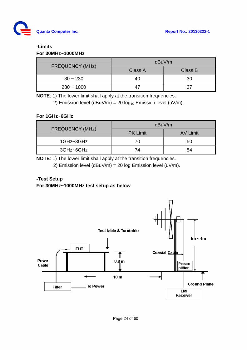
-Limits For 30MHz~1000MHz
FREQUENCY (MHz) dBuV/m
Class A Class B
30 ~ 230 40 30
230 ~ 1000 47 37
NOTE: 1) The lower limit shall apply at the transition frequencies. 2) Emission level (dBuV/m) = 20 log10 Emission level (uV/m).
For 1GHz~6GHz
FREQUENCY (MHz) dBuV/m
PK Limit AV Limit
1GHz~3GHz 70 50
3GHz~6GHz 74 54
NOTE: 1) The lower limit shall apply at the transition frequencies. 2) Emission level (dBuV/m) = 20 log Emission level (uV/m).
-Test Setup For 30MHz~1000MHz test setup as below
Quanta Computer Inc. Report No.: 20130222-1
Page 25 of 60
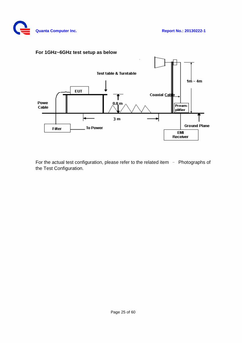
For 1GHz~6GHz test setup as below
For the actual test configuration, please refer to the related item – Photographs of the Test Configuration.
Quanta Computer Inc. Report No.: 20130222-1
Page 26 of 60
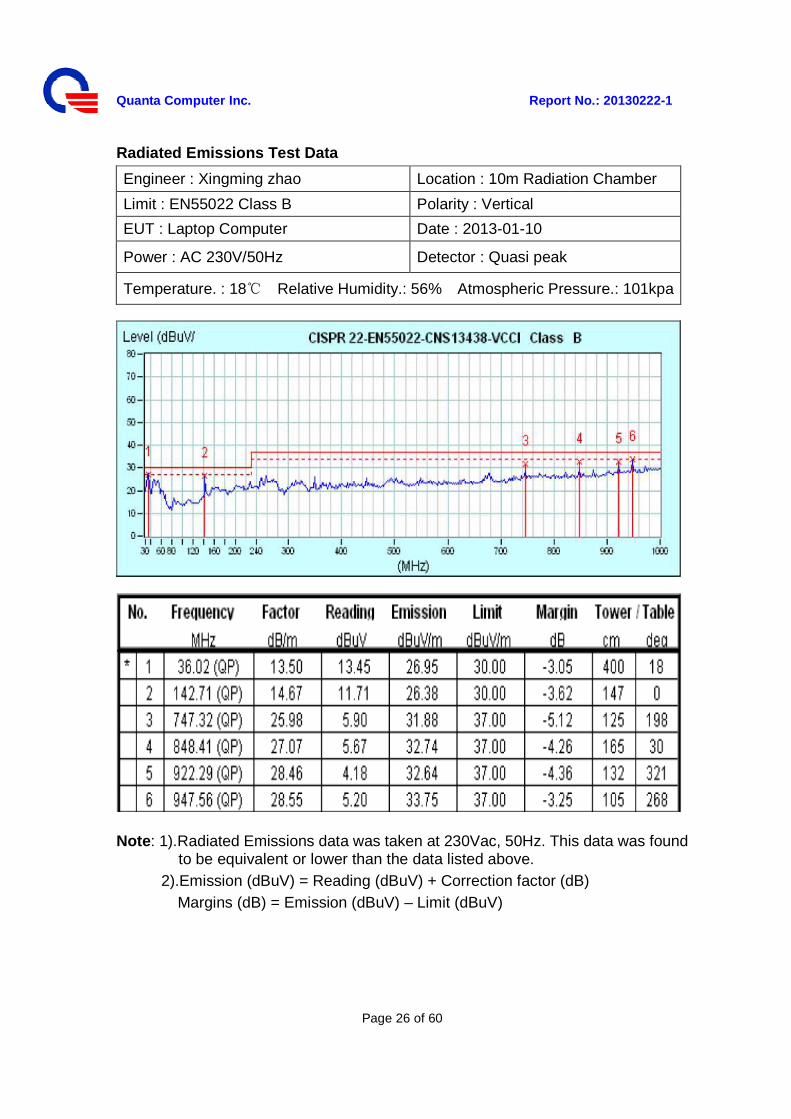
Radiated Emissions Test Data
Engineer : Xingming zhao Location : 10m Radiation Chamber
Limit : EN55022 Class B Polarity : Vertical
EUT : Laptop Computer Date : 2013-01-10
Power : AC 230V/50Hz Detector : Quasi peak
Temperature. : 18 Relative Humidity.: 56% Atmospheric Pressure.: 101kpa
Note: 1).Radiated Emissions data was taken at 230Vac, 50Hz. This data was found to be equivalent or lower than the data listed above.
2).Emission (dBuV) = Reading (dBuV) + Correction factor (dB) Margins (dB) = Emission (dBuV) – Limit (dBuV)
Quanta Computer Inc. Report No.: 20130222-1
Page 27 of 60
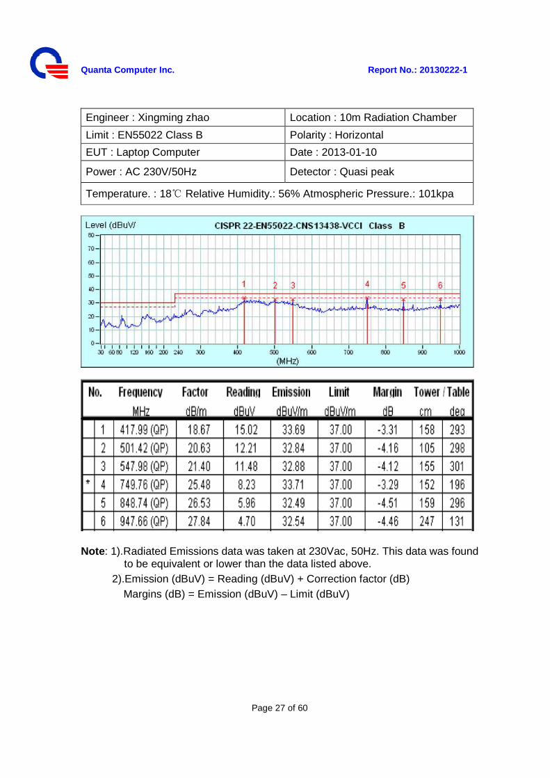
Engineer : Xingming zhao Location : 10m Radiation Chamber
Limit : EN55022 Class B Polarity : Horizontal
EUT : Laptop Computer Date : 2013-01-10
Power : AC 230V/50Hz Detector : Quasi peak
Temperature. : 18 Relative Humidity.: 56% Atmospheric Pressure.: 101kpa
Note: 1).Radiated Emissions data was taken at 230Vac, 50Hz. This data was found to be equivalent or lower than the data listed above.
2).Emission (dBuV) = Reading (dBuV) + Correction factor (dB) Margins (dB) = Emission (dBuV) – Limit (dBuV)
Quanta Computer Inc. Report No.: 20130222-1
Page 28 of 60
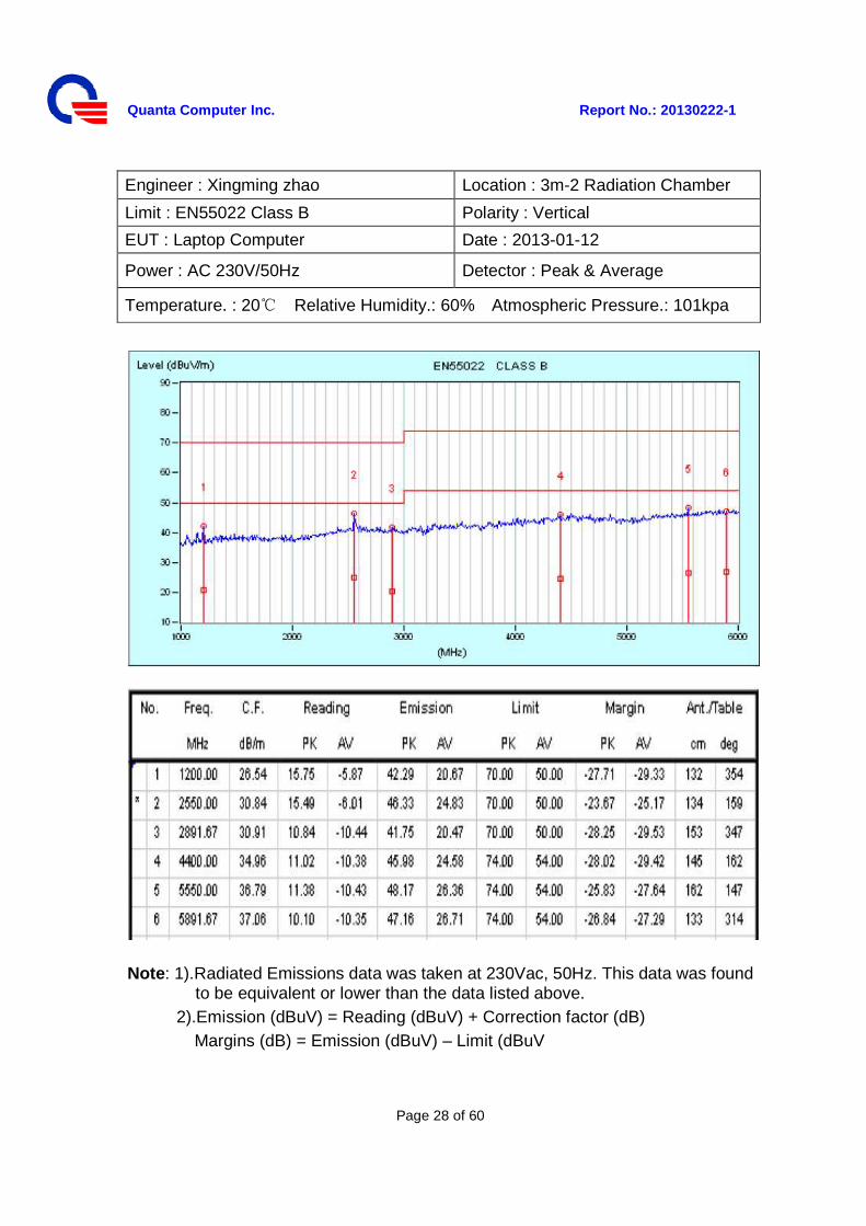
Engineer : Xingming zhao Location : 3m-2 Radiation Chamber
Limit : EN55022 Class B Polarity : Vertical
EUT : Laptop Computer Date : 2013-01-12
Power : AC 230V/50Hz Detector : Peak & Average
Temperature. : 20 Relative Humidity.: 60% Atmospheric Pressure.: 101kpa
Note: 1).Radiated Emissions data was taken at 230Vac, 50Hz. This data was found to be equivalent or lower than the data listed above.
2).Emission (dBuV) = Reading (dBuV) + Correction factor (dB) Margins (dB) = Emission (dBuV) – Limit (dBuV
Quanta Computer Inc. Report No.: 20130222-1
Page 29 of 60
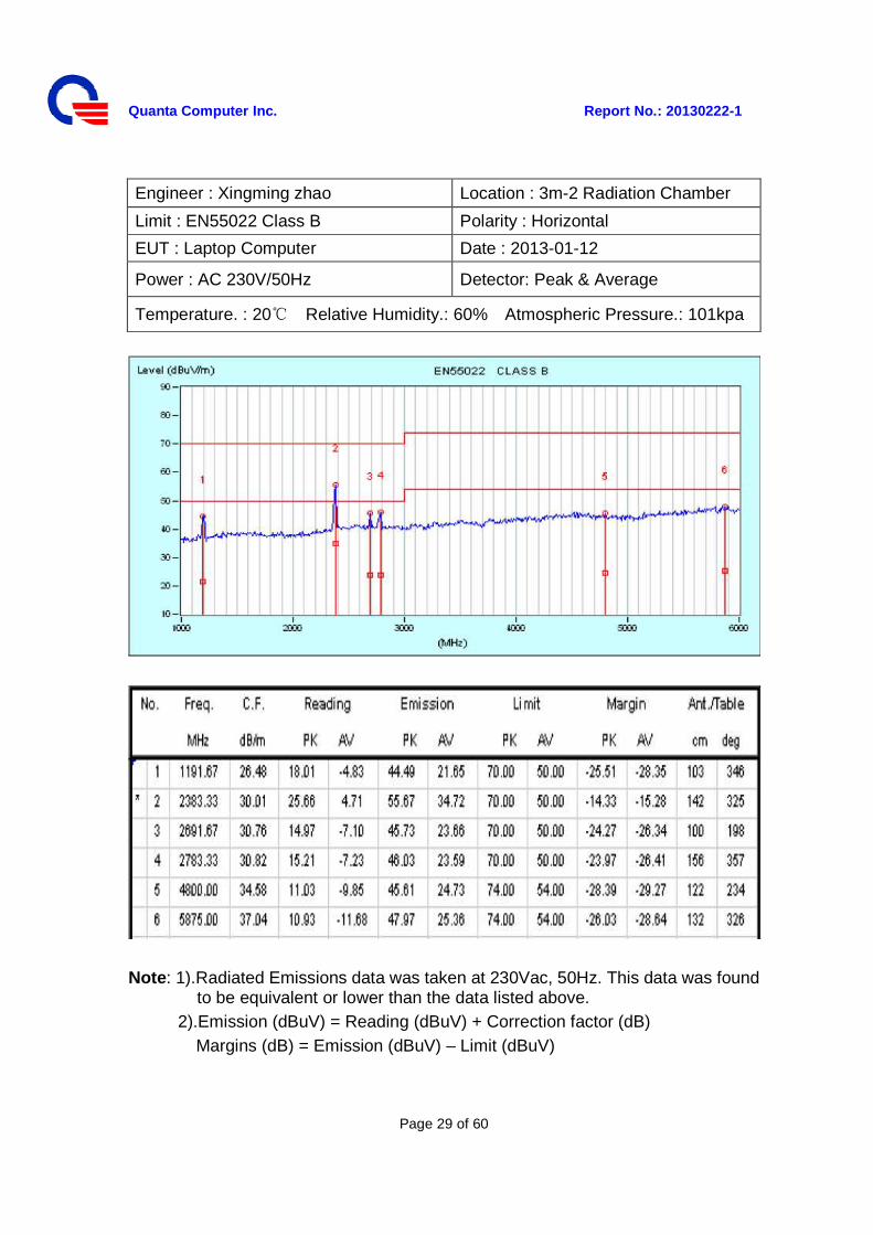
Engineer : Xingming zhao Location : 3m-2 Radiation Chamber
Limit : EN55022 Class B Polarity : Horizontal
EUT : Laptop Computer Date : 2013-01-12
Power : AC 230V/50Hz Detector: Peak & Average
Temperature. : 20 Relative Humidity.: 60% Atmospheric Pressure.: 101kpa
Note: 1).Radiated Emissions data was taken at 230Vac, 50Hz. This data was found
to be equivalent or lower than the data listed above. 2).Emission (dBuV) = Reading (dBuV) + Correction factor (dB)
Margins (dB) = Emission (dBuV) – Limit (dBuV)
Quanta Computer Inc. Report No.: 20130222-1
Page 30 of 60
3.1.3 Power Harmonics Measurement The product was tested and met the requirements specified in EN61000-3-2. - Measurement Procedures Utilized for Harmonics 1) The EUT was placed on the top of a wooden table 0.8 meters above the ground
and operated to produce the maximum harmonic components under normal operating conditions for each successive harmonic component in turn.
2) The classification of EUT is according to section 5 of EN 61000-3-2.
3) The EUT is classified as follows:
Class A: Balanced three-phase equipment, Household appliances excluding equipment as Class D, Tools excluding portable tools, Dimmers for incandescent lamps, audio equipment, equipment not specified in one of the three other classes.
Class B: Portable tools; Arc welding equipment which is not professional equipment.
Class C: Lighting equipment.
Class D: Equipment having a specified power less than or equal to 600 W of the following types: Personal computers and personal computer monitors and television receivers.
4) The correspondent test program of test instrument to measure the current harmonics emanated from EUT is chosen. The measure time shall be not less than the time necessary for the EUT to be exercised.
Quanta Computer Inc. Report No.: 20130222-1
Page 31 of 60
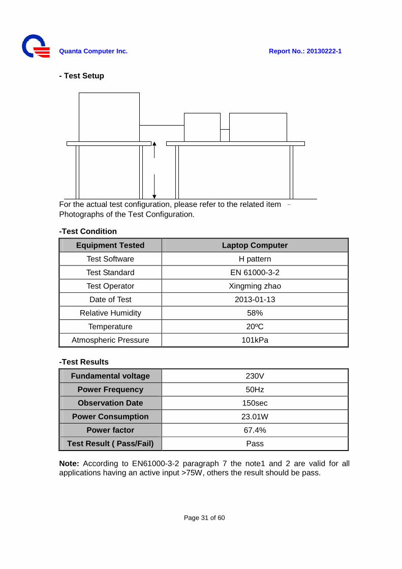
- Test Setup
For the actual test configuration, please refer to the related item – Photographs of the Test Configuration.
-Test Condition
Equipment Tested Laptop Computer
Test Software H pattern
Test Standard EN 61000-3-2
Test Operator Xingming zhao
Date of Test 2013-01-13
Relative Humidity 58%
Temperature 20ºC
Atmospheric Pressure 101kPa
-Test Results
Fundamental voltage 230V
Power Frequency 50Hz
Observation Date 150sec
Power Consumption 23.01W
Power factor 67.4%
Test Result ( Pass/Fail) Pass
Note: According to EN61000-3-2 paragraph 7 the note1 and 2 are valid for all applications having an active input >75W, others the result should be pass.
Quanta Computer Inc. Report No.: 20130222-1
Page 32 of 60
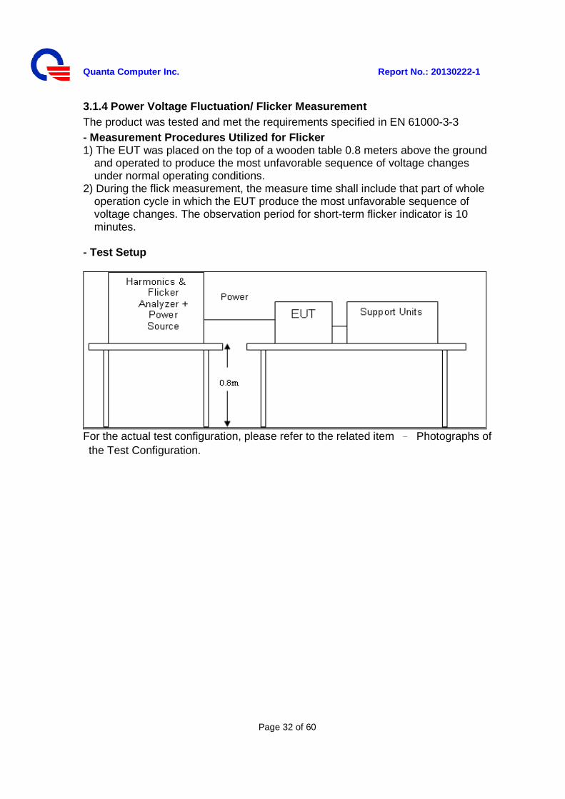
3.1.4 Power Voltage Fluctuation/ Flicker Measurement The product was tested and met the requirements specified in EN 61000-3-3 - Measurement Procedures Utilized for Flicker 1) The EUT was placed on the top of a wooden table 0.8 meters above the ground
and operated to produce the most unfavorable sequence of voltage changes under normal operating conditions.
2) During the flick measurement, the measure time shall include that part of whole operation cycle in which the EUT produce the most unfavorable sequence of voltage changes. The observation period for short-term flicker indicator is 10 minutes.
- Test Setup
For the actual test configuration, please refer to the related item – Photographs of the Test Configuration.
Quanta Computer Inc. Report No.: 20130222-1
Page 33 of 60
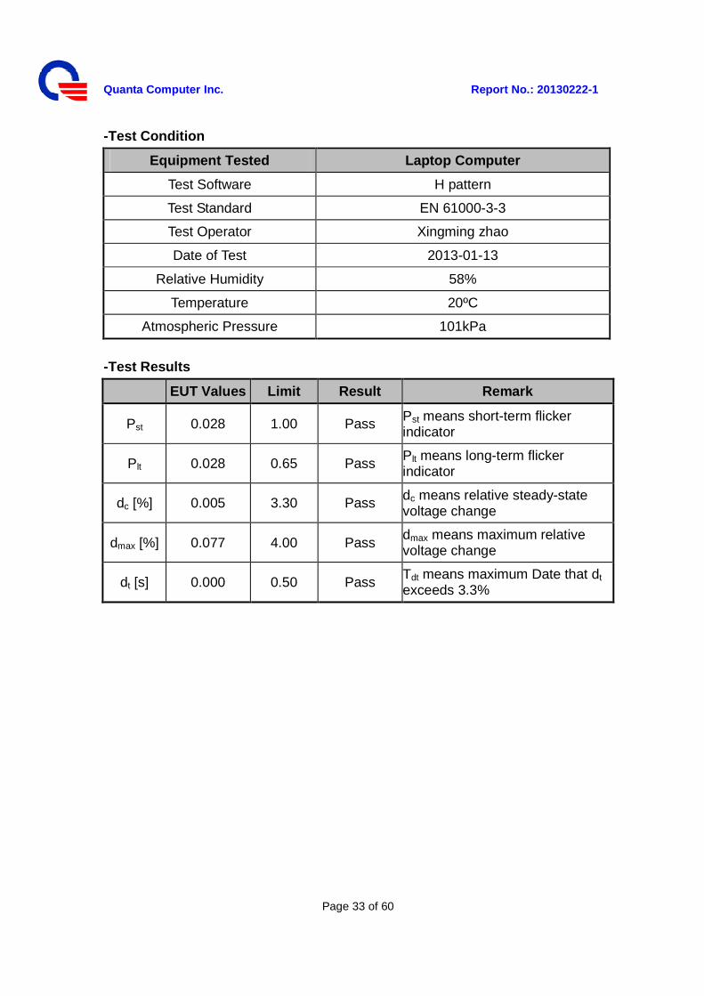
-Test Condition
Equipment Tested Laptop Computer
Test Software H pattern
Test Standard EN 61000-3-3
Test Operator Xingming zhao
Date of Test 2013-01-13
Relative Humidity 58%
Temperature 20ºC
Atmospheric Pressure 101kPa
-Test Results
EUT Values Limit Result Remark
Pst 0.028 1.00 Pass Pst means short-term flicker indicator
Plt 0.028 0.65 Pass Plt means long-term flicker indicator
dc [%] 0.005 3.30 Pass dc means relative steady-state voltage change
dmax [%] 0.077 4.00 Pass dmax means maximum relative voltage change
dt [s] 0.000 0.50 Pass Tdt means maximum Date that dt exceeds 3.3%
Quanta Computer Inc. Report No.: 20130222-1
Page 34 of 60
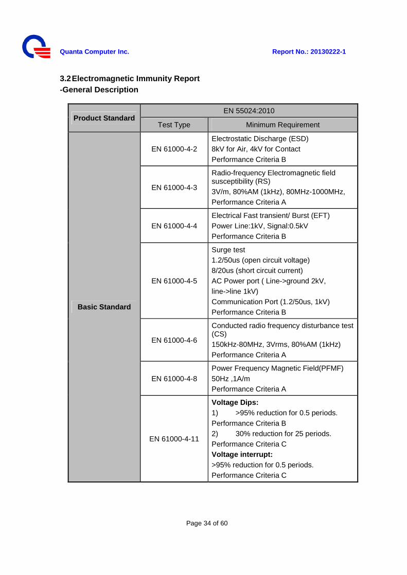
3.2 Electromagnetic Immunity Report -General Description
Product Standard EN 55024:2010
Test Type Minimum Requirement
Basic Standard
EN 61000-4-2 Electrostatic Discharge (ESD) 8kV for Air, 4kV for Contact Performance Criteria B
EN 61000-4-3
Radio-frequency Electromagnetic field susceptibility (RS) 3V/m, 80%AM (1kHz), 80MHz-1000MHz, Performance Criteria A
EN 61000-4-4 Electrical Fast transient/ Burst (EFT) Power Line:1kV, Signal:0.5kV Performance Criteria B
EN 61000-4-5
Surge test 1.2/50us (open circuit voltage) 8/20us (short circuit current) AC Power port ( Line->ground 2kV, line->line 1kV) Communication Port (1.2/50us, 1kV) Performance Criteria B
EN 61000-4-6
Conducted radio frequency disturbance test (CS) 150kHz-80MHz, 3Vrms, 80%AM (1kHz) Performance Criteria A
EN 61000-4-8 Power Frequency Magnetic Field(PFMF) 50Hz ,1A/m Performance Criteria A
EN 61000-4-11
Voltage Dips: 1) >95% reduction for 0.5 periods. Performance Criteria B 2) 30% reduction for 25 periods. Performance Criteria C Voltage interrupt: >95% reduction for 0.5 periods. Performance Criteria C
Quanta Computer Inc. Report No.: 20130222-1
Page 35 of 60
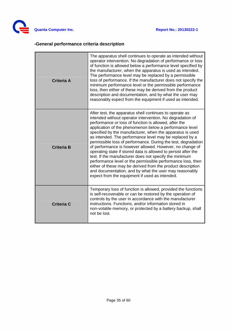
-General performance criteria description
Criteria A
The apparatus shell continues to operate as intended without operator intervention. No degradation of performance or loss of function is allowed below a performance level specified by the manufacturer, when the apparatus is used as intended. The performance level may be replaced by a permissible loss of performance. If the manufacturer does not specify the minimum performance level or the permissible performance loss, then either of these may be derived from the product description and documentation, and by what the user may reasonably expect from the equipment if used as intended.
Criteria B
After test, the apparatus shell continues to operate as intended without operator intervention. No degradation of performance or loss of function is allowed, after the application of the phenomenon below a performance level specified by the manufacturer, when the apparatus is used as intended. The performance level may be replaced by a permissible loss of performance. During the test, degradation of performance is however allowed. However, no change of operating state if stored data is allowed to persist after the test. If the manufacturer does not specify the minimum performance level or the permissible performance loss, then either of these may be derived from the product description and documentation, and by what the user may reasonably expect from the equipment if used as intended.
Criteria C
Temporary loss of function is allowed, provided the functions is self-recoverable or can be restored by the operation of controls by the user in accordance with the manufacturer instructions. Functions, and/or information stored in non-volatile memory, or protected by a battery backup, shall not be lost.
Quanta Computer Inc. Report No.: 20130222-1
Page 36 of 60
3.2.1 Electrostatic Discharge (ESD) Immunity Measurement The product was tested and met the requirements specified in EN 61000-4-2 - Measurement Procedures Utilized for ESD The discharges shall be applied in two ways:
a) Contact discharges to the conductive surfaces and coupling planes: The EUT shall be exposed to at least 200 discharges, 100 each at negative and positive polarity, at a minimum of four test points. One of the test points shall be subjected to at least 50 indirect discharges to the center of the front edge of the Horizontal Coupling Plane (HCP). The remaining three test points shall each receive at least 50 direct contact discharges. If no direct contact test points, then at least 200 indirect discharges shall be applied in the indirect mode. Test shall be performed at a maximum repetition rate of one discharge per second.
b) Air discharges at slots and apertures and insulating surfaces: On those parts of the EUT where it is not possible to perform contact discharge testing, the equipment should be investigated to identify user accessible points where breakdown may occur. Such points are tested using the air discharge method. This investigation should be restricted to those area normally handled by the user. A minimum of 10 single air discharges shall be applied to the selected test point for each such area.
The basic test procedure was in accordance with IEC 61000-4-2:
a) The EUT was located 0.1 m minimum from all side of the HCP (dimensions 1.6m x 0.8m).
b) The support units were located another table 30 cm away from the EUT, but direct support unit was/were located at same location as EUT on the HCP and keep at a distance of 10 cm with EUT.
c) The time interval between two successive single discharges was at least 1 second.
d) Contact discharges were applied to the non-insulating coating, with the pointed tip of the generator penetrating the coating and contacting the conducting substrate.
e) Air discharges were applied with the round discharge tip of the discharge electrode approaching the EUT as fast as possible (without causing mechanical damage) to touch the EUT. After each discharge, the ESD generator was removed from the EUT and re-triggered for a new single discharge. The test was repeated until all discharges were complete.
f) At least ten single discharges (in the most sensitive polarity) were applied at the front edge of each HCP opposite the center point of each unit of the EUT and 0.1 meters from the front of the EUT. The long axis of the discharge electrode was in the plane of the HCP and perpendicular to its front edge during the discharge.
Quanta Computer Inc. Report No.: 20130222-1
Page 37 of 60
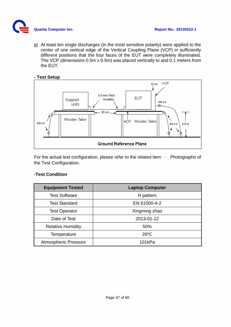
g) At least ten single discharges (in the most sensitive polarity) were applied to the center of one vertical edge of the Vertical Coupling Plane (VCP) in sufficiently different positions that the four faces of the EUT were completely illuminated. The VCP (dimensions 0.5m x 0.5m) was placed vertically to and 0.1 meters from the EUT.
- Test Setup
For the actual test configuration, please refer to the related item – Photographs of the Test Configuration.
-Test Condition
Equipment Tested Laptop Computer
Test Software H pattern
Test Standard EN 61000-4-2
Test Operator Xingming zhao
Date of Test 2013-01-12
Relative Humidity 50%
Temperature 26ºC
Atmospheric Pressure 101kPa
Quanta Computer Inc. Report No.: 20130222-1
Page 38 of 60
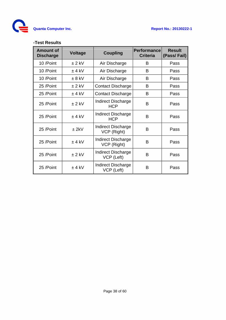
-Test Results
Amount of Discharge Voltage Coupling Performance
Criteria Result
(Pass/ Fail)
10 /Point ± 2 kV Air Discharge B Pass
10 /Point ± 4 kV Air Discharge B Pass
10 /Point ± 8 kV Air Discharge B Pass
25 /Point ± 2 kV Contact Discharge B Pass
25 /Point ± 4 kV Contact Discharge B Pass
25 /Point ± 2 kV Indirect Discharge HCP B Pass
25 /Point ± 4 kV Indirect Discharge HCP B Pass
25 /Point ± 2kV Indirect Discharge
VCP (Right) B Pass
25 /Point ± 4 kV Indirect Discharge VCP (Right) B Pass
25 /Point ± 2 kV Indirect Discharge VCP (Left)
B Pass
25 /Point ± 4 kV Indirect Discharge
VCP (Left) B Pass
Quanta Computer Inc. Report No.: 20130222-1
Page 39 of 60
3.2.2 Radiated Electromagnetic Field Immunity Test The product was tested and met the requirements specified in EN 61000-4-3 - Measurement Procedures Utilized for RS
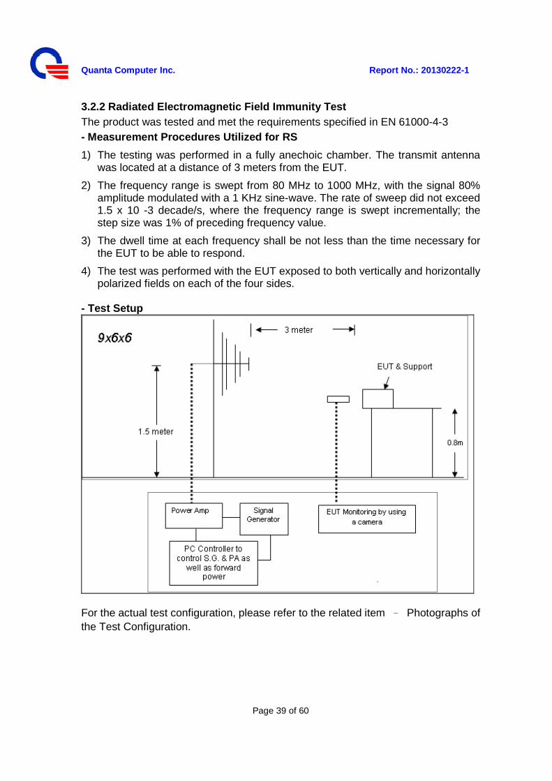
1) The testing was performed in a fully anechoic chamber. The transmit antenna was located at a distance of 3 meters from the EUT.
2) The frequency range is swept from 80 MHz to 1000 MHz, with the signal 80% amplitude modulated with a 1 KHz sine-wave. The rate of sweep did not exceed 1.5 x 10 -3 decade/s, where the frequency range is swept incrementally; the step size was 1% of preceding frequency value.
3) The dwell time at each frequency shall be not less than the time necessary for the EUT to be able to respond.
4) The test was performed with the EUT exposed to both vertically and horizontally polarized fields on each of the four sides.
- Test Setup
For the actual test configuration, please refer to the related item – Photographs of the Test Configuration.
Quanta Computer Inc. Report No.: 20130222-1
Page 40 of 60
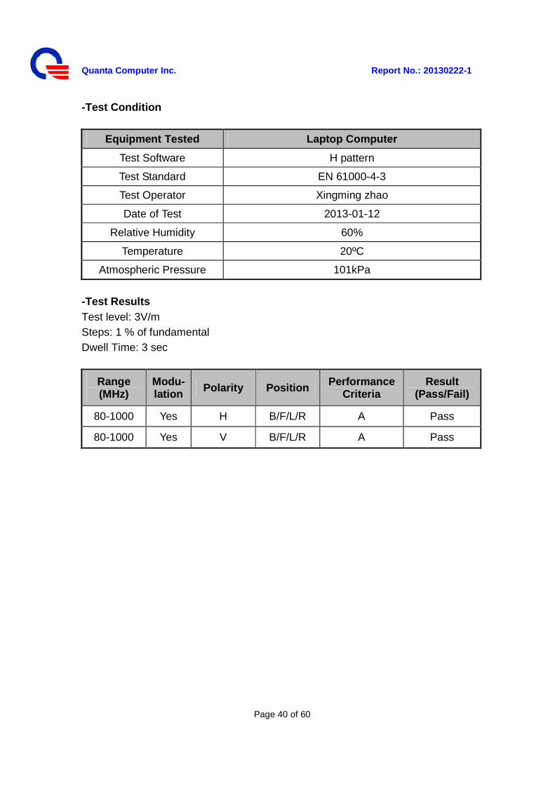
-Test Condition
Equipment Tested Laptop Computer
Test Software H pattern
Test Standard EN 61000-4-3
Test Operator Xingming zhao
Date of Test 2013-01-12
Relative Humidity 60%
Temperature 20ºC
Atmospheric Pressure 101kPa
-Test Results Test level: 3V/m Steps: 1 % of fundamental Dwell Time: 3 sec
Range (MHz)
Modu-lation Polarity Position Performance
Criteria Result
(Pass/Fail)
80-1000 Yes H B/F/L/R A Pass
80-1000 Yes V B/F/L/R A Pass
Quanta Computer Inc. Report No.: 20130222-1
Page 41 of 60
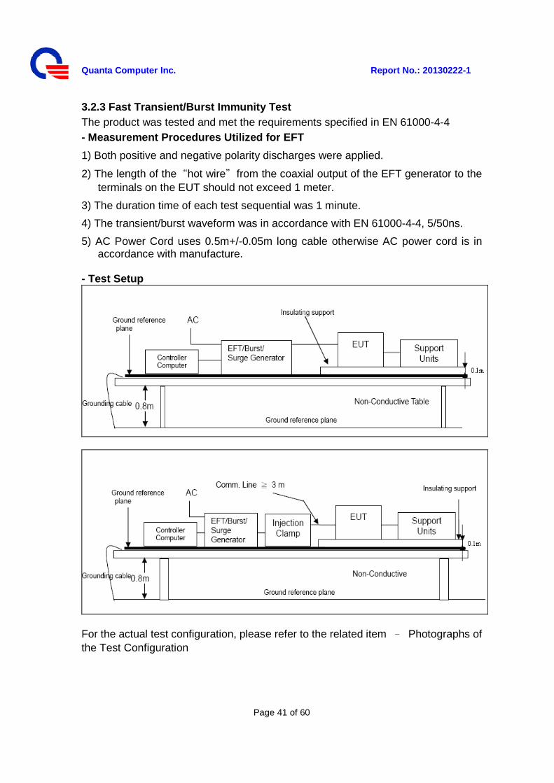
3.2.3 Fast Transient/Burst Immunity Test The product was tested and met the requirements specified in EN 61000-4-4 - Measurement Procedures Utilized for EFT
1) Both positive and negative polarity discharges were applied.
2) The length of the“hot wire”from the coaxial output of the EFT generator to the terminals on the EUT should not exceed 1 meter.
3) The duration time of each test sequential was 1 minute.
4) The transient/burst waveform was in accordance with EN 61000-4-4, 5/50ns.
5) AC Power Cord uses 0.5m+/-0.05m long cable otherwise AC power cord is in accordance with manufacture.
- Test Setup
For the actual test configuration, please refer to the related item – Photographs of the Test Configuration
Quanta Computer Inc. Report No.: 20130222-1
Page 42 of 60
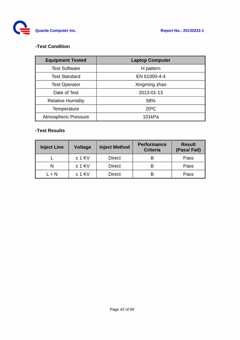
-Test Condition
Equipment Tested Laptop Computer
Test Software H pattern
Test Standard EN 61000-4-4
Test Operator Xingming zhao
Date of Test 2013-01-13
Relative Humidity 58%
Temperature 20ºC
Atmospheric Pressure 101kPa
-Test Results
Inject Line Voltage Inject Method Performance Criteria
Result (Pass/ Fail)
L ± 1 KV Direct B Pass
N ± 1 KV Direct B Pass
L + N ± 1 KV Direct B Pass
Quanta Computer Inc. Report No.: 20130222-1
Page 43 of 60
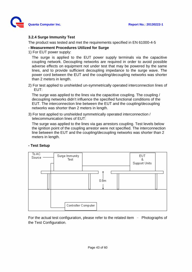
3.2.4 Surge Immunity Test The product was tested and met the requirements specified in EN 61000-4-5 - Measurement Procedures Utilized for Surge 1) For EUT power supply:
The surge is applied to the EUT power supply terminals via the capacitive coupling network. Decoupling networks are required in order to avoid possible adverse effects on equipment not under test that may be powered by the same lines, and to provide sufficient decoupling impedance to the surge wave. The power cord between the EUT and the coupling/decoupling networks was shorter than 2 meters in length.
2) For test applied to unshielded un-symmetrically operated interconnection lines of EUT:
The surge was applied to the lines via the capacitive coupling. The coupling / decoupling networks didn’t influence the specified functional conditions of the EUT. The interconnection line between the EUT and the coupling/decoupling networks was shorter than 2 meters in length.
3) For test applied to unshielded symmetrically operated interconnection / telecommunication lines of EUT: The surge was applied to the lines via gas arrestors coupling. Test levels below the ignition point of the coupling arrestor were not specified. The interconnection line between the EUT and the coupling/decoupling networks was shorter than 2 meters in length.
- Test Setup
For the actual test configuration, please refer to the related item – Photographs of the Test Configuration.
Quanta Computer Inc. Report No.: 20130222-1
Page 44 of 60
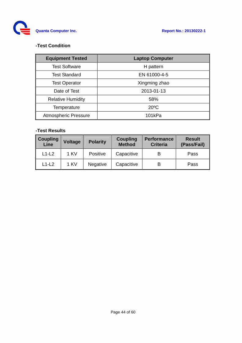
-Test Condition
Equipment Tested Laptop Computer
Test Software H pattern
Test Standard EN 61000-4-5
Test Operator Xingming zhao
Date of Test 2013-01-13
Relative Humidity 58%
Temperature 20ºC
Atmospheric Pressure 101kPa
-Test Results
Coupling Line Voltage Polarity
Coupling Method
Performance Criteria
Result (Pass/Fail)
L1-L2 1 KV Positive Capacitive B Pass
L1-L2 1 KV Negative Capacitive B Pass
Quanta Computer Inc. Report No.: 20130222-1
Page 45 of 60
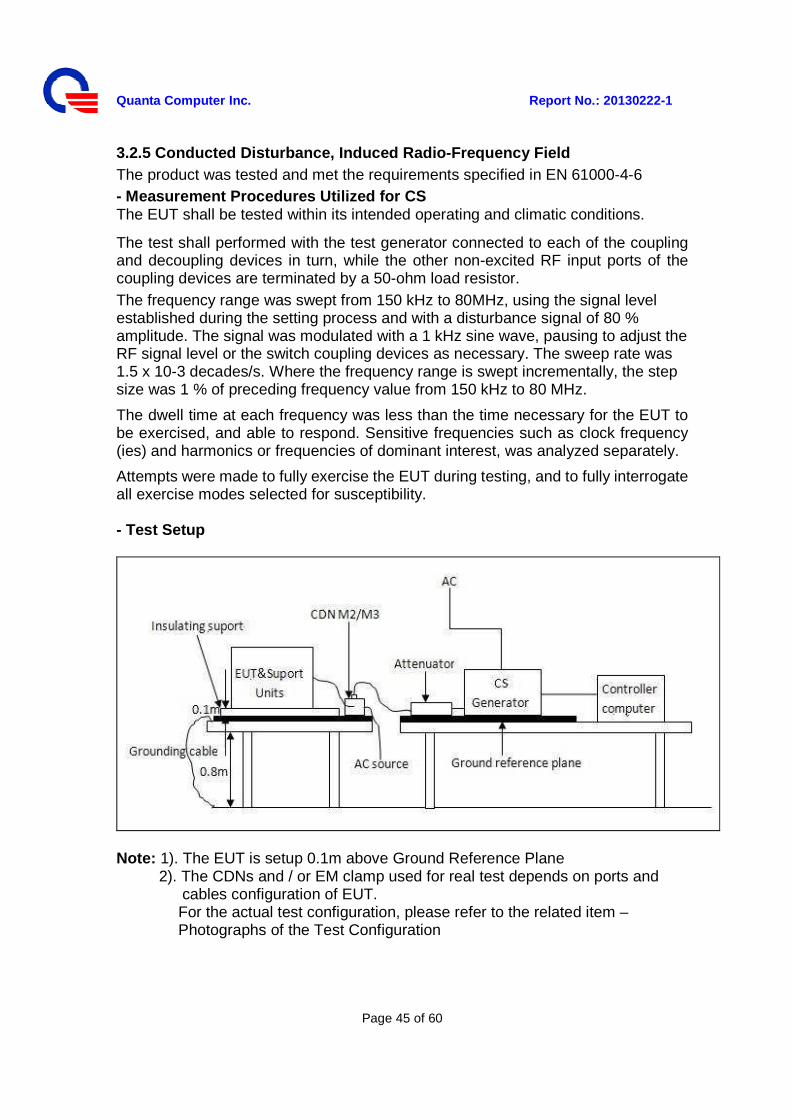
3.2.5 Conducted Disturbance, Induced Radio-Frequency Field The product was tested and met the requirements specified in EN 61000-4-6 - Measurement Procedures Utilized for CS The EUT shall be tested within its intended operating and climatic conditions.
The test shall performed with the test generator connected to each of the coupling and decoupling devices in turn, while the other non-excited RF input ports of the coupling devices are terminated by a 50-ohm load resistor. The frequency range was swept from 150 kHz to 80MHz, using the signal level established during the setting process and with a disturbance signal of 80 % amplitude. The signal was modulated with a 1 kHz sine wave, pausing to adjust the RF signal level or the switch coupling devices as necessary. The sweep rate was 1.5 x 10⁻³ decades/s. Where the frequency range is swept incrementally, the step size was 1 % of preceding frequency value from 150 kHz to 80 MHz.
The dwell time at each frequency was less than the time necessary for the EUT to be exercised, and able to respond. Sensitive frequencies such as clock frequency (ies) and harmonics or frequencies of dominant interest, was analyzed separately.
Attempts were made to fully exercise the EUT during testing, and to fully interrogate all exercise modes selected for susceptibility. - Test Setup
Note: 1). The EUT is setup 0.1m above Ground Reference Plane
2). The CDNs and / or EM clamp used for real test depends on ports and cables configuration of EUT. For the actual test configuration, please refer to the related item – Photographs of the Test Configuration

Quanta Computer Inc. Report No.: 20130222-1
Page 46 of 60
-Test Condition
Equipment Tested Laptop Computer
Test Software H pattern
Test Standard EN 61000-4-6
Test Operator Xingming zhao
Date of Test 2013-01-13
Relative Humidity 58%
Temperature 20ºC
Atmospheric Pressure 101kPa
-Test Results Frequency Step: 1% of fundamental Dwell Time: 3 sec Test Ports: mains
Range (MHz) Field Modulation Performance
Criteria Result
(Pass/ Fail)
0.15-80 3V Yes A Pass
Quanta Computer Inc. Report No.: 20130222-1
Page 47 of 60
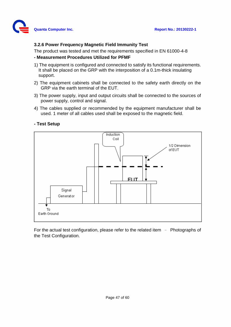
3.2.6 Power Frequency Magnetic Field Immunity Test The product was tested and met the requirements specified in EN 61000-4-8 - Measurement Procedures Utilized for PFMF
1) The equipment is configured and connected to satisfy its functional requirements. It shall be placed on the GRP with the interposition of a 0.1m-thick insulating support.
2) The equipment cabinets shall be connected to the safety earth directly on the GRP via the earth terminal of the EUT.
3) The power supply, input and output circuits shall be connected to the sources of power supply, control and signal.
4) The cables supplied or recommended by the equipment manufacturer shall be used. 1 meter of all cables used shall be exposed to the magnetic field.
- Test Setup
For the actual test configuration, please refer to the related item – Photographs of the Test Configuration.
Quanta Computer Inc. Report No.: 20130222-1
Page 48 of 60
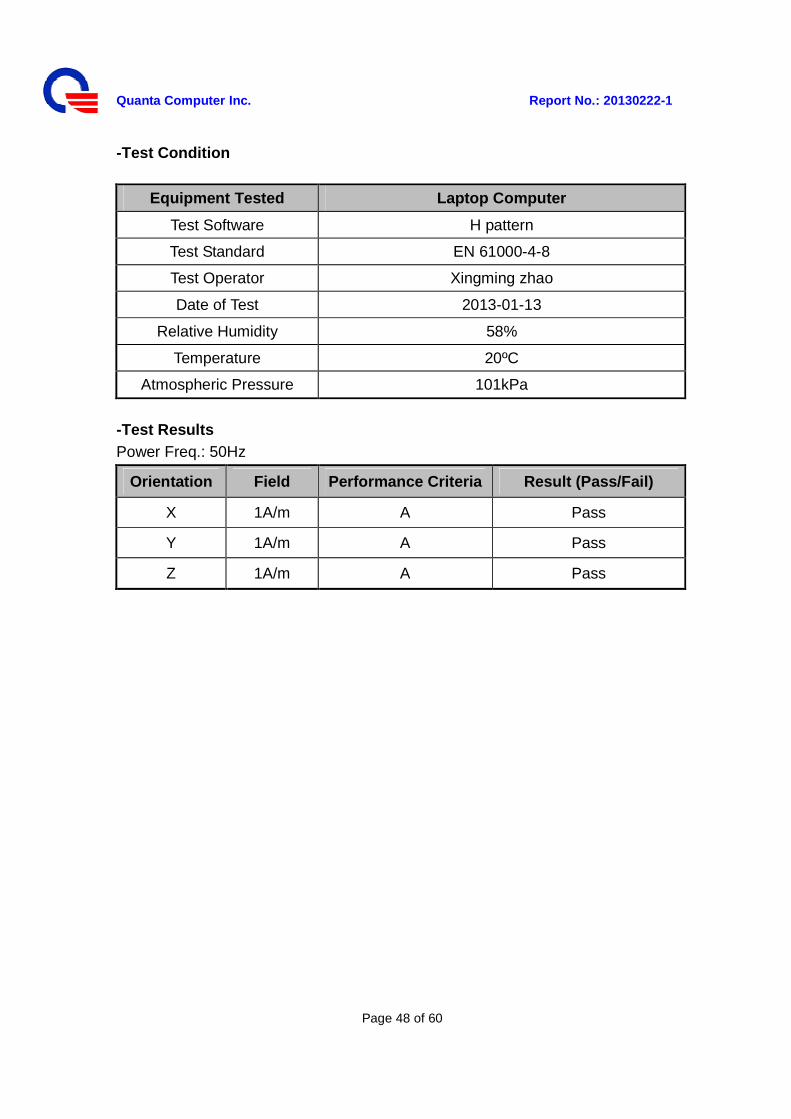
-Test Condition
Equipment Tested Laptop Computer
Test Software H pattern
Test Standard EN 61000-4-8
Test Operator Xingming zhao
Date of Test 2013-01-13
Relative Humidity 58%
Temperature 20ºC
Atmospheric Pressure 101kPa
-Test Results Power Freq.: 50Hz
Orientation Field Performance Criteria Result (Pass/Fail)
X 1A/m A Pass
Y 1A/m A Pass
Z 1A/m A Pass
Quanta Computer Inc. Report No.: 20130222-1
Page 49 of 60
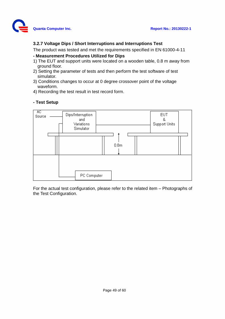
3.2.7 Voltage Dips / Short Interruptions and Interruptions Test The product was tested and met the requirements specified in EN 61000-4-11 - Measurement Procedures Utilized for Dips 1) The EUT and support units were located on a wooden table, 0.8 m away from
ground floor. 2) Setting the parameter of tests and then perform the test software of test
simulator. 3) Conditions changes to occur at 0 degree crossover point of the voltage
waveform. 4) Recording the test result in test record form. - Test Setup
For the actual test configuration, please refer to the related item – Photographs of the Test Configuration.
Quanta Computer Inc. Report No.: 20130222-1
Page 50 of 60
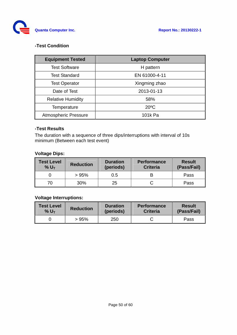
-Test Condition
Equipment Tested Laptop Computer
Test Software H pattern
Test Standard EN 61000-4-11
Test Operator Xingming zhao
Date of Test 2013-01-13
Relative Humidity 58%
Temperature 20ºC
Atmospheric Pressure 101k Pa
-Test Results The duration with a sequence of three dips/interruptions with interval of 10s minimum (Between each test event)
Voltage Dips:
Test Level % UT Reduction Duration
(periods) Performance
Criteria Result
(Pass/Fail)
0 > 95% 0.5 B Pass
70 30% 25 C Pass
Voltage Interruptions:
Test Level % UT Reduction
Duration (periods)
Performance Criteria
Result (Pass/Fail)
0 > 95% 250 C Pass
Quanta Computer Inc. Report No.: 20130222-1
Page 51 of 60
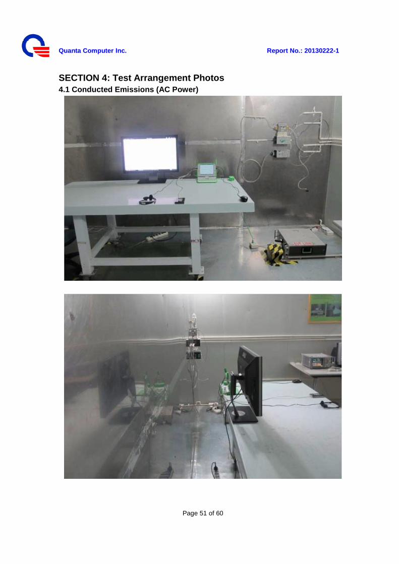
SECTION 4: Test Arrangement Photos 4.1 Conducted Emissions (AC Power)
Quanta Computer Inc. Report No.: 20130222-1
Page 52 of 60
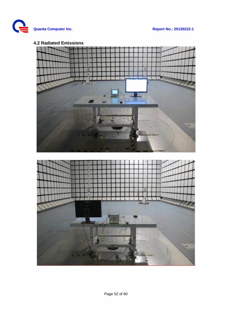
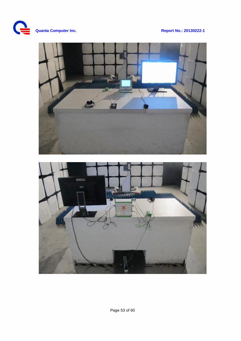
4.2 Radiated Emissions
Quanta Computer Inc. Report No.: 20130222-1
Page 53 of 60
Quanta Computer Inc. Report No.: 20130222-1
Page 54 of 60
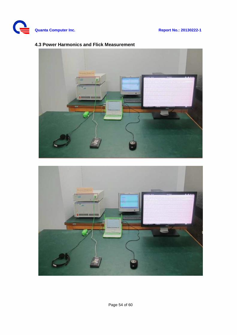
4.3 Power Harmonics and Flick Measurement
Quanta Computer Inc. Report No.: 20130222-1
Page 55 of 60
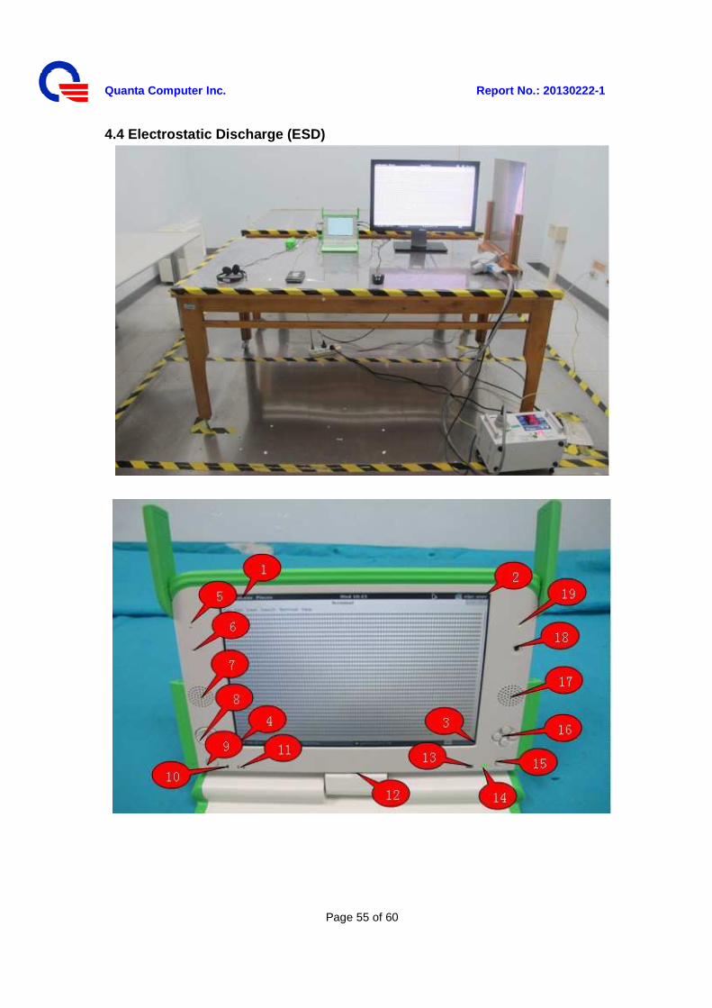
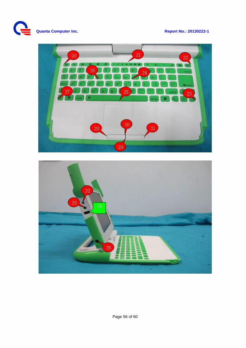
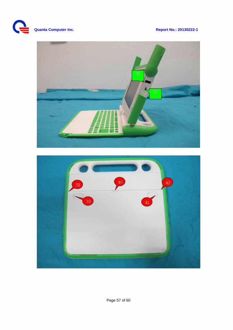
4.4 Electrostatic Discharge (ESD)
Quanta Computer Inc. Report No.: 20130222-1
Page 56 of 60
Quanta Computer Inc. Report No.: 20130222-1
Page 57 of 60
Quanta Computer Inc. Report No.: 20130222-1
Page 58 of 60
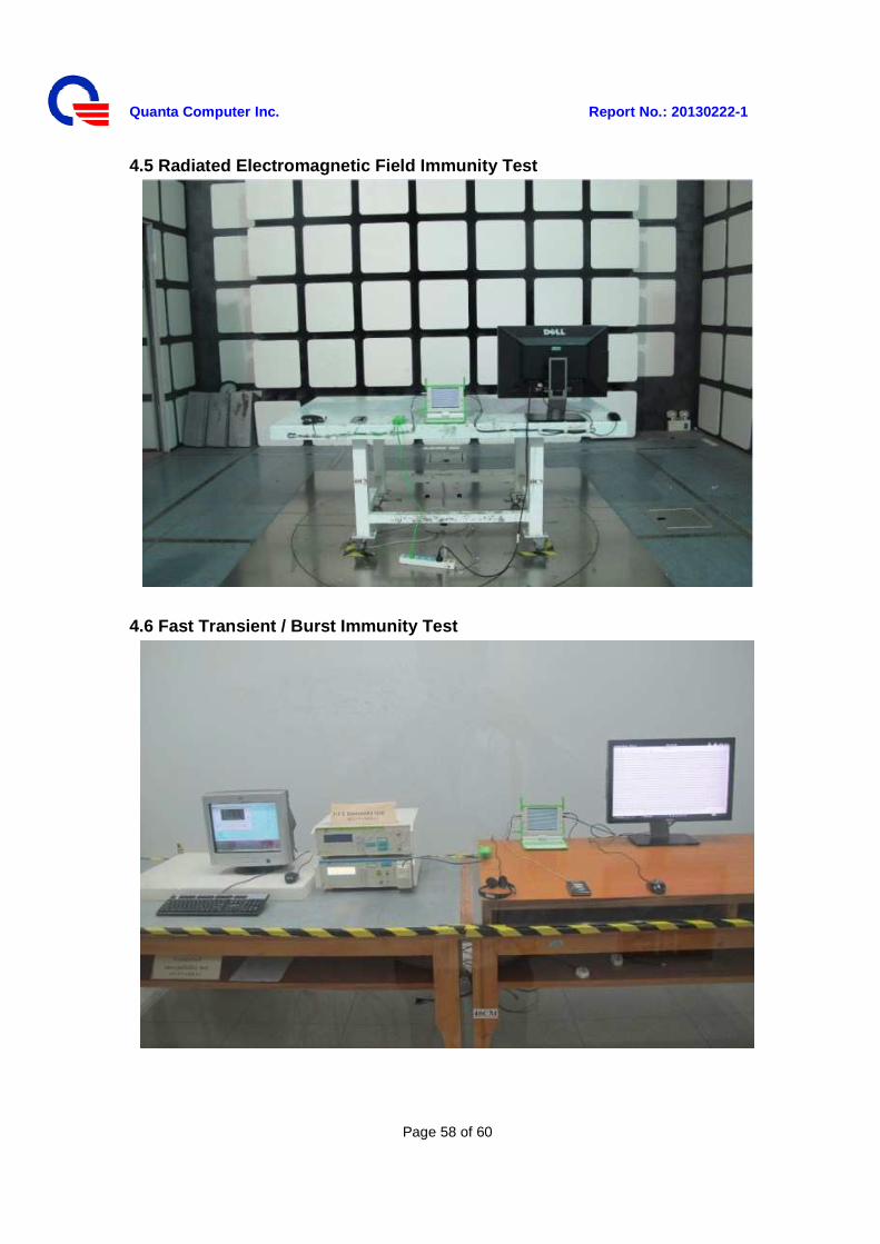
4.5 Radiated Electromagnetic Field Immunity Test
4.6 Fast Transient / Burst Immunity Test
Quanta Computer Inc. Report No.: 20130222-1
Page 59 of 60
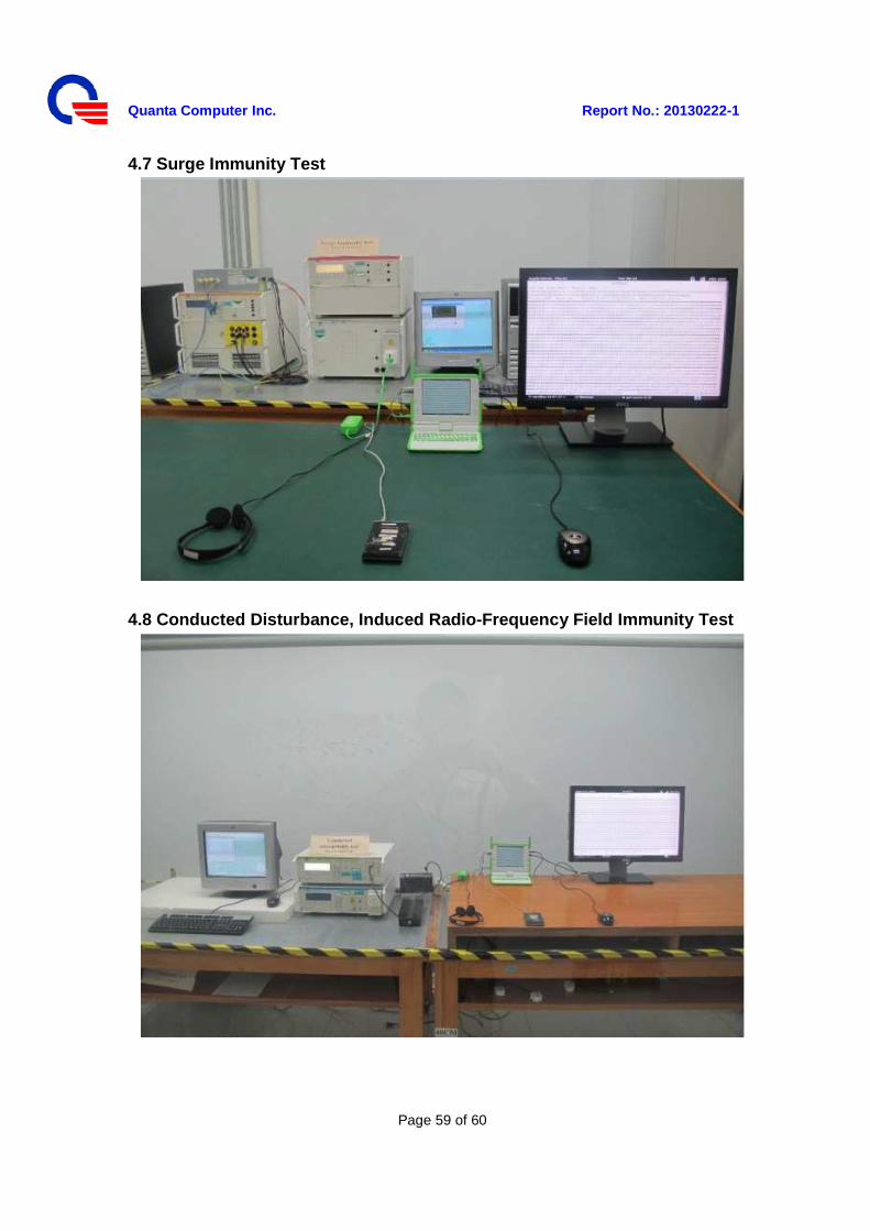
4.7 Surge Immunity Test
4.8 Conducted Disturbance, Induced Radio-Frequency Field Immunity Test
Quanta Computer Inc. Report No.: 20130222-1
Page 60 of 60
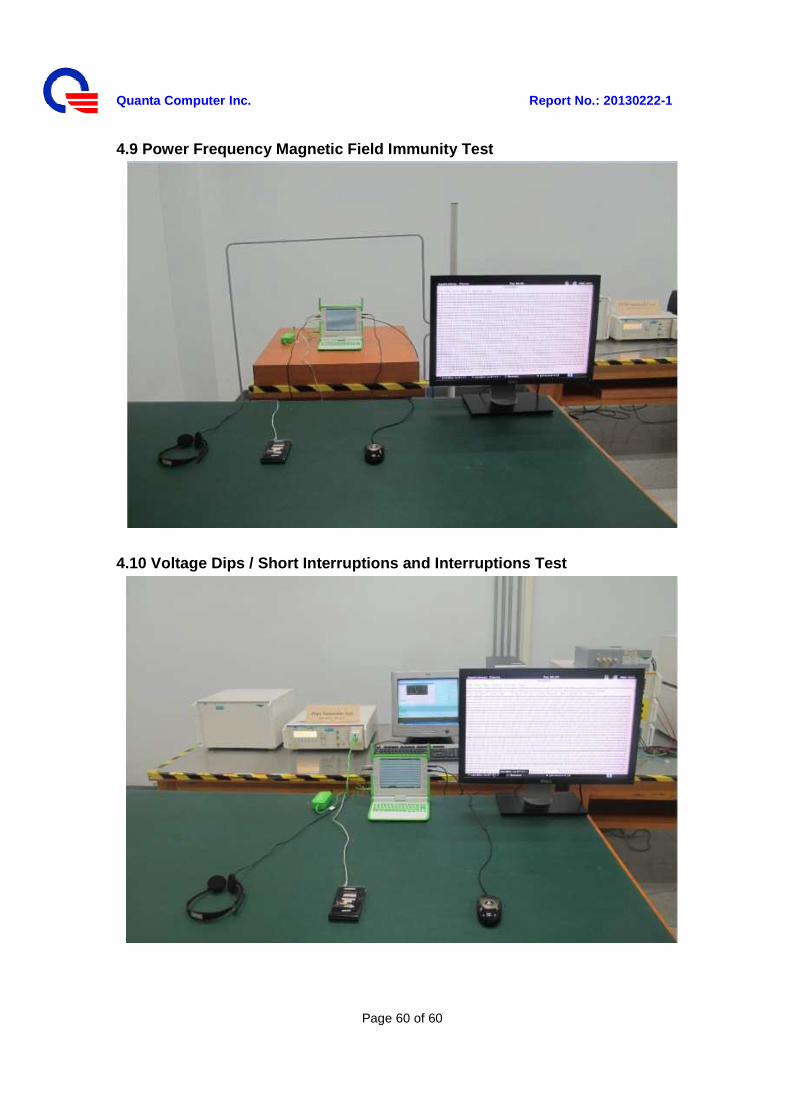
4.9 Power Frequency Magnetic Field Immunity Test
4.10 Voltage Dips / Short Interruptions and Interruptions Test