Embed Size (px)
Citation preview

SP-096016 (NEW)
SPECIAL PROVISION
FOR
WATER MAIN
Linn County
ESL-4775(620)--7S-57
Effective Date:
December 15, 2009
THE IOWA DEPARTMENT OF TRANSPORTATION STANDARD SPECIFICATIONS FOR HIGHWAY AND BRIDGE CONSTRUCTION, SERIES 2009, ARE AMENDED BY THE
FOLLOWING ADDITIONS, OR MODIFICATIONS. THESE ARE SPECIAL PROVISIONS AND SHALL PREVAIL OVER THOSE PUBLISHED IN THE STANDARD SPECIFICATIONS.
SP-096016 Page 2 of 21
PART 1 DESCRIPTION 1.01 - Section Includes
A. Water Mains. B. Water Services. C. Bolts and Fittings. D. Valves and Valve Boxes. E. Fire Hydrant Assemblies. F. Blowoff Assemblies. G. Air Release Assemblies.
1.02- Description
A. Water Mains – This item includes furnishing and installing water pipe in accordance with the Contract Documents.
B. Water Services – This item includes furnishing and installing water services, and constructing a water service tap (per jurisdictional requirements for City-made tap, see paragraph 3.09.F) on an existing water main which does not have an existing service connection in the required location, in accordance with the Contract Documents.
C. Bolts and Fittings – This item includes furnishing and installing bolts and fittings in accordance with the Contract Documents.
D. Valves and Valve Boxes – This item includes furnishing and installing valves and valve boxes, including gate valves, butterfly valves, and tapping valves and sleeves, in accordance with the Contract Documents.
E. Fire Hydrant Assemblies – This item includes furnishing and installing fire hydrant assemblies in accordance with the Contract Documents.
F. Blowoff Assemblies – This item includes furnishing and installing blowoff assemblies associated with a water main, in accordance with the Contract Documents.
G. Air Release Assemblies – This item includes furnishing and installing air release assemblies associated with a water main, in accordance with the Contract Documents.
1.03 - Submittals
A. Submit test results as set forth in the Contract Documents. B. Submit certificate of compliance indicating the materials incorporated into the Work
comply with the Contract Documents. C. The substitution of materials is allowed as set forth in General Conditions. D. Submit joint restraint system.
1.04 - Delivery, Storage and Handling
A. Store material in accordance with the manufacturers’ recommendations and in locations that will minimize the interference with operations, minimize environmental damage, and protect adjacent areas from flooding, runoff and sediment disposition.
1.05 - Scheduling and Conflicts
A. Schedule Work to minimize disruption of public streets and facilities. B. Discontinue Work that will be affected by any conflicts discovered or any changes
needed to accommodate unknown or changed conditions and notify the Engineer. 1.06 - Special Requirements
A. The use of explosives is not permitted unless provided for in the special provisions of the Contract Documents.
B. All work under this section shall be performed by a plumber or pipe layer licensed by the Metro Plumbing Licensing Board. Licensing may be obtained at the Cedar Rapids Building Department for all metropolitan area jurisdictions.
SP-096016 Page 3 of 21
C. Unless noted otherwise in the Contract Documents, all materials are to be furnished and installed by the Contractor. Refer to Jurisdictional Special Provisions for exceptions.
D. Unless noted otherwise in the Contract Documents, all labor & equipment is to be furnished by the Contractor . Refer to Jurisdictional Special Provisions for exceptions.
PART 2 MATERIALS 2.01 - Water Mains
A. Ductile Iron Pipe 1. Minimum thickness class
a. 4-inch through 12-inch: Class 52 per ANSI/AWWA C151/A21.51. b. 16-inch through 20-inch: Pressure Class 250 per ANSI/AWWA C151/A21.51. c. 24-inch: Pressure Class 200 per ANSI/AWWA C151/A21.51. d. 30-inch through 48-inch: Pressure Class 150 per ANSI/AWWA C151/A21.51. e. Special Provisions – See Appendix A.
2. Cement-mortar lined, per ANSI/AWWA C104/A21.4 with asphaltic seal coat. 3. External coating: asphaltic. 4. Joint Type: Use push-on type, except where specifically authorized by Engineer.
a. Push-on: per ANSI/AWWA C111/A21.11. b. Mechanical: per ANSI/AWWA C111/A21.11. c. Restrained, buried: Pipe manufacturer’s standard field removable system. d. Restrained, in structures: Restraining gland, flanged or grooved. e. Flanged: ANSI/AWWA C111/A21.11. f. Grooved: ANSI/AWWA C606. g. Gaskets: Per ANSI/AWWA C111/A21.11.
5. Markings on pipe: Name of manufacturer; size and class; and spigot insertion depth gauge.
B. Polyvinyl Chloride (PVC) Pipe (Hiawatha and Marion Only) 1. Conform to ANSI/AWWA C900 or C905 with cast iron pipe equivalent outside
diameters. 2. Wall thicknesses:
a. 4-inch through 12-inch sizes: DR 18. b. Sizes over 12 inches: Refer to Plans.
3. Markings on pipe: Name of manufacturer; size and class; spigot insertion depth gauge; and National Sanitation Foundation (NSF) seal.
4. Integral elastomeric gasket in bell end. 2.02 - Water Services
A. Refer also to approved service pipe table, in Appendix B of this section. B. Controlling standards: Local water service, plumbing and fire codes. C. Materials
1. Copper Pipe: Conform to ASTM B88. Wall thickness: Type K. 2. Ductile Iron Pipe: As specified in Section 2.01. Polyethylene wrap is required.
D. Corporation stop: 1-inch minimum. Stop inlet with AWWA threads. Manufacturer as listed in appendix B or approved equal.
E. Curb stop: 1-inch minimum ball valve. Valve size same as service size. Quarter-turn check. Manufacturer as listed in appendix B or approved equal.
F. Curb box. 1. 1-inch diameter upper half. Stem arch pattern. Height adjustable from 4 ft to 6 ft. 2. Manufacturer: as listed in Appendix B. 3. Special Provisions – See Appendix A.
G. Tapping Saddle. 1. Ductile iron bodies with fusion bonded epoxy coating. 2. Double stainless steel straps with Buna-N gasket seal. 3. Manufacturer: as listed in Appendix B or approved equal.
SP-096016 Page 4 of 21
2.03 - Bolts For Water Main Pipe And Fittings Corrosion resistant uncoated Cor-Ten steel bolts. 2.04 - Fittings
A. For Ductile Iron Pipe 1. Fittings shall comply with ANSI/AWWA C110/A21.10 or ANSI/AWWA C153/A21.53. 2. Joint Type: Mechanical or restrained, as required by Engineer. 3. Cement-mortar lined per ANSI/AWWA C104/A21.4 with asphaltic coating or unlined
with fusion bonded epoxy per AWWA C116. 4. Restrained Joints 5. Restrained Mechanical Joints: Pipe manufacturer's standard field-removable system. 6. Flanged: ANSI/AWWA C110/A21.10. Nuts shall conform to ASTM A 563, Grade A,
heavy hex head. Gaskets shall be rubber or approved composition; 0.125-inch thick; full face.
7. Grooved: ANSI/AWWA C606. Face to face dimensions shall be equivalent to flanged, ANSI/AWWA C110/A21.10. a. 5. Wall thickness: ANSI/AWWA C153/A21.53. b. 6. Gaskets: Per ANSI/AWWA C111/A21.11.
8. Fittings shall be smooth and pit free. Coatings shall be uniform and undamaged. B. For Polyvinyl Chloride (PVC) Pipe use only ductile iron mechanical joint fittings as
specified elsewhere in this section. 2.05 - Special Fittings
A. Flange Adapter 1. Use where noted on Drawings to allow for ease of dismantling piping in the future. 2. Model: Style 127 as manufactured by Dresser Manufacturing Division, Bradford,
Pennsylvania; 912 as manufactured by Smith-Blair. 3. Substitutions: Approved equal.
B. Ductile Iron Sleeve. 1. Use on buried piping to allow for dismantling piping in future or for connecting two
buried plain end pipes. 2. Long body sleeves are required. 3. Mechanical joint, ANSI/AWWA C110/A21.10.
C. Restrained Joints. 1. Use to restrain mechanical joint where required by Engineer. 2. Manufacturer: Ebaa Iron, Inc.; Megalug; One Bolt, Oxford, AL; Romac “Grip Ring.” 3. Substitutions: Pipe manufacturer’s standard field removable restraint system. 4. Suitable for buried service. 5. Corrosion resistant components. 6. Designed by pipe manufacturer, conforming to DIPRA "Thrust Restraint Design for
Ductile Iron Pipe", latest edition. 7. Joint restraint system to be field installable, field removable and reinstallable. 8. Restraint systems involving pipe clamps and connecting rods are not acceptable
unless specifically required in the Contract Documents. 9. Joint restraint system approval; in writing from Engineer. 10. Contract Documents shall identify locations and number of joints to be restrained.
D. Couplings 1. Use to join two spigot ends of two pieces of pipe 2. Ductile Iron couplings are to be used for joining pipe sizes up to and including 12-inch. 3. Carbon Steel couplings are to be used for joining pipes greater than 12-inch. Minimum
laying length shall be 14 inches. Minimum yield strength of 30,000 psi. 4. Bodies of all couplings are to be Epoxy Coated inside and outside per AWWA C213 5. All bolts, nuts, and hardware are to be grade 304 stainless steel or better.
SP-096016 Page 5 of 21
2.06 - Concrete Thrust Blocks
A. Application: 1. For use with pipe sizes up to 16 inch diameter unless approved by
Engineer. 2. For pipe sizes greater than 16-inch diameter, use restraining glands
or manufacturers standard restraint system per Paragraph 2.04. B. Refer to detailed Drawings for dimensions and installation of thrust blocks. C. Concrete minimum compressive strength is 3000 psi.
2.07 - Pipe Line Accessories
A. Polyethylene Wrap: See Appendix A for required usage. Minimum thickness 8 mils. Conform to ANSI/AWWA C105/A21.5.
B. Tracer System 1. Use on ductile iron pipe larger than 16-inch diameter and on all PVC pipe. 2. Tracer Wire: #12 solid single strand, type TW or THHN. 3. Ground Rod: 3/8-inch diameter, 60-inch long steel rod uniformly coated with
metallically bonded electrolytic copper. Ground-rod clamp: High-strength, corrosion-resistant copper alloy.
4. Splice Kit: Buried service wire splice. 5. Receptacle Post: 1 lb/ft. channel post 4 feet long. UP-1 by Grimco, Inc., or equal. 6. Receptacle Box: Top-hinged ABS plastic enclosure or equal. 7. Terminations: Scotchcast terminating kit or equal. 8. Splice Bolt: #8F brass split bolt manufactured by Reliable Power Products, Inc. or
approved equal. C. Insulation: Extruded polystyrene conforming to ASTM C-578; high-density, moisture
resistant, suitable for underground installation. Owens Corning or equal 2.08 - Gaskets, Special Use special pipe gaskets in contaminated soils if so directed by Engineer. In soils contaminated with gasoline, use nitrile material; for other soil contaminants, use material as required by Engineer. 2.09 - Valves
A. General 1. Same size as pipeline in which it is installed, unless noted otherwise on Drawings. 2. Manufacturer’s name or initial and working pressure cast on valve body. 3. Open when turned left or right as required by jurisdiction – See Appendix A. Opening
direction arrow shall be cast on operating nut. 4. Factory tested to twice the rated working pressure. 5. Buried service: Mechanical joints, unless noted otherwise. 6. Service within structure: Flanged, per ANSI/AWWA C110/A21.10. Flanges drilled to
conform to ASME/ANSI B16.1 class 125, unless noted otherwise. All valve operators to be supplied by valve supplier.
7. Bolts for joints: Refer to paragraph 2.03.A. B. Butterfly Valves, Buried Service
1. Use: 16-inch diameter and larger 2. Type: Rubber seat. 3. Pressure rating: 150-psi working pressure. 4. Bubble-tight at rated pressures with flow in either direction. 5. Comply with: ANSI/AWWA C504 class 150B. 6. Body: Cast iron per ASTM A 126 class B; two trunnions for shaft
bearings. 2. Ends: Mechanical joint, except as otherwise shown in the Plans. 3. Disc: Cast iron ASTM A126 class B, with plasma-applied nickel-chromium edge;
connected to shaft by mechanically fixed stainless steel pins.
SP-096016 Page 6 of 21
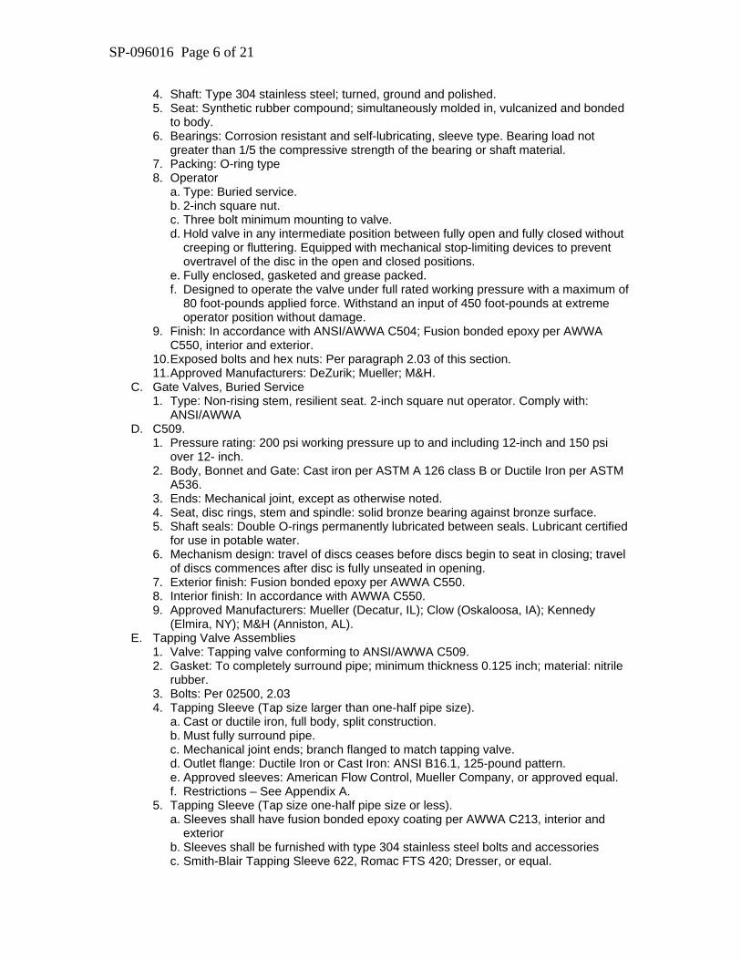
4. Shaft: Type 304 stainless steel; turned, ground and polished. 5. Seat: Synthetic rubber compound; simultaneously molded in, vulcanized and bonded
to body. 6. Bearings: Corrosion resistant and self-lubricating, sleeve type. Bearing load not
greater than 1/5 the compressive strength of the bearing or shaft material. 7. Packing: O-ring type 8. Operator
a. Type: Buried service. b. 2-inch square nut. c. Three bolt minimum mounting to valve. d. Hold valve in any intermediate position between fully open and fully closed without
creeping or fluttering. Equipped with mechanical stop-limiting devices to prevent overtravel of the disc in the open and closed positions.
e. Fully enclosed, gasketed and grease packed. f. Designed to operate the valve under full rated working pressure with a maximum of
80 foot-pounds applied force. Withstand an input of 450 foot-pounds at extreme operator position without damage.
9. Finish: In accordance with ANSI/AWWA C504; Fusion bonded epoxy per AWWA C550, interior and exterior.
10. Exposed bolts and hex nuts: Per paragraph 2.03 of this section. 11. Approved Manufacturers: DeZurik; Mueller; M&H.
C. Gate Valves, Buried Service 1. Type: Non-rising stem, resilient seat. 2-inch square nut operator. Comply with:
ANSI/AWWA D. C509.
1. Pressure rating: 200 psi working pressure up to and including 12-inch and 150 psi over 12- inch.
2. Body, Bonnet and Gate: Cast iron per ASTM A 126 class B or Ductile Iron per ASTM A536.
3. Ends: Mechanical joint, except as otherwise noted. 4. Seat, disc rings, stem and spindle: solid bronze bearing against bronze surface. 5. Shaft seals: Double O-rings permanently lubricated between seals. Lubricant certified
for use in potable water. 6. Mechanism design: travel of discs ceases before discs begin to seat in closing; travel
of discs commences after disc is fully unseated in opening. 7. Exterior finish: Fusion bonded epoxy per AWWA C550. 8. Interior finish: In accordance with AWWA C550. 9. Approved Manufacturers: Mueller (Decatur, IL); Clow (Oskaloosa, IA); Kennedy
(Elmira, NY); M&H (Anniston, AL). E. Tapping Valve Assemblies
1. Valve: Tapping valve conforming to ANSI/AWWA C509. 2. Gasket: To completely surround pipe; minimum thickness 0.125 inch; material: nitrile
rubber. 3. Bolts: Per 02500, 2.03 4. Tapping Sleeve (Tap size larger than one-half pipe size).
a. Cast or ductile iron, full body, split construction. b. Must fully surround pipe. c. Mechanical joint ends; branch flanged to match tapping valve. d. Outlet flange: Ductile Iron or Cast Iron: ANSI B16.1, 125-pound pattern. e. Approved sleeves: American Flow Control, Mueller Company, or approved equal. f. Restrictions – See Appendix A.
5. Tapping Sleeve (Tap size one-half pipe size or less). a. Sleeves shall have fusion bonded epoxy coating per AWWA C213, interior and
exterior b. Sleeves shall be furnished with type 304 stainless steel bolts and accessories c. Smith-Blair Tapping Sleeve 622, Romac FTS 420; Dresser, or equal.
SP-096016 Page 7 of 21
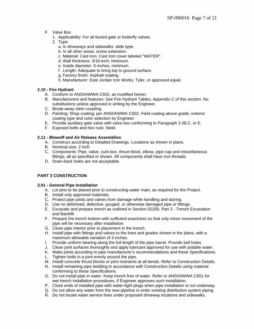
F. Valve Box 1. Applicability: For all buried gate or butterfly valves. 2. Type:
a. In driveways and sidewalks: slide type. b. In all other areas; screw extension. c. Material: Cast iron. Cast iron cover labeled “WATER”. d. Wall thickness: 3/16-inch, minimum. e. Inside diameter: 5-inches, minimum. f. Length: Adequate to bring top to ground surface. g. Factory finish: Asphalt coating. h. Manufacturer: East Jordan Iron Works, Tyler, or approved equal.
2.10 - Fire Hydrant
A. Conform to ANSI/AWWA C502, as modified herein. B. Manufacturers and features: See Fire Hydrant Tables, Appendix C of this section. No
substitutions unless approved in writing by the Engineer. C. Break-away stem coupling. D. Painting: Shop coating; per ANSI/AWWA C502. Field coating above grade; exterior
coating type and color selection by Engineer. E. Provide auxiliary gate valve with valve box conforming to Paragraph 2.08.C. or E. F. Exposed bolts and hex nuts: Steel.
2.11 - Blowoff and Air Release Assemblies
A. Construct according to Detailed Drawings. Locations as shown in plans. B. Nominal size: 2 inch C. Components: Pipe, valve, curb box, thrust block, elbow, pipe cap and miscellaneous
fittings, all as specified or shown. All components shall have iron threads. D. Drain-back holes are not acceptable.
PART 3 CONSTRUCTION 3.01 - General Pipe Installation
A. Lot pins to be placed prior to constructing water main, as required for the Project. B. Install only approved materials. C. Protect pipe joints and valves from damage while handling and storing. D. Use no deformed, defective, gouged, or otherwise damaged pipe or fittings. E. Excavate and prepare trench as outlined in Section 02200, Part 3 - Trench Excavation
and Backfill. F. Prepare the trench bottom with sufficient exactness so that only minor movement of the
pipe will be necessary after installation. G. Clean pipe interior prior to placement in the trench. H. Install pipe with fittings and valves to the lines and grades shown in the plans, with a
maximum allowable variation of 3 inches. I. Provide uniform bearing along the full length of the pipe barrel. Provide bell holes. J. Clean joint surfaces thoroughly and apply lubricant approved for use with potable water. K. Make joints according to pipe manufacturer’s recommendations and these Specifications. L. Tighten bolts in a joint evenly around the pipe. M. Install concrete thrust blocks or joint restraints at all bends. Refer to Construction Details. N. Install remaining pipe bedding in accordance with Construction Details using material
conforming to these Specifications. O. Do not install pipe in water. Keep trench free of water. Refer to ANSI/AWWA C651 for
wet trench installation procedures, if Engineer approves such installation. P. Close ends of installed pipe with water-tight plugs when pipe installation is not underway. Q. Do not allow any water from the new pipeline to enter existing distribution system piping. R. Do not locate water service lines under proposed driveway locations and sidewalks.
SP-096016 Page 8 of 21
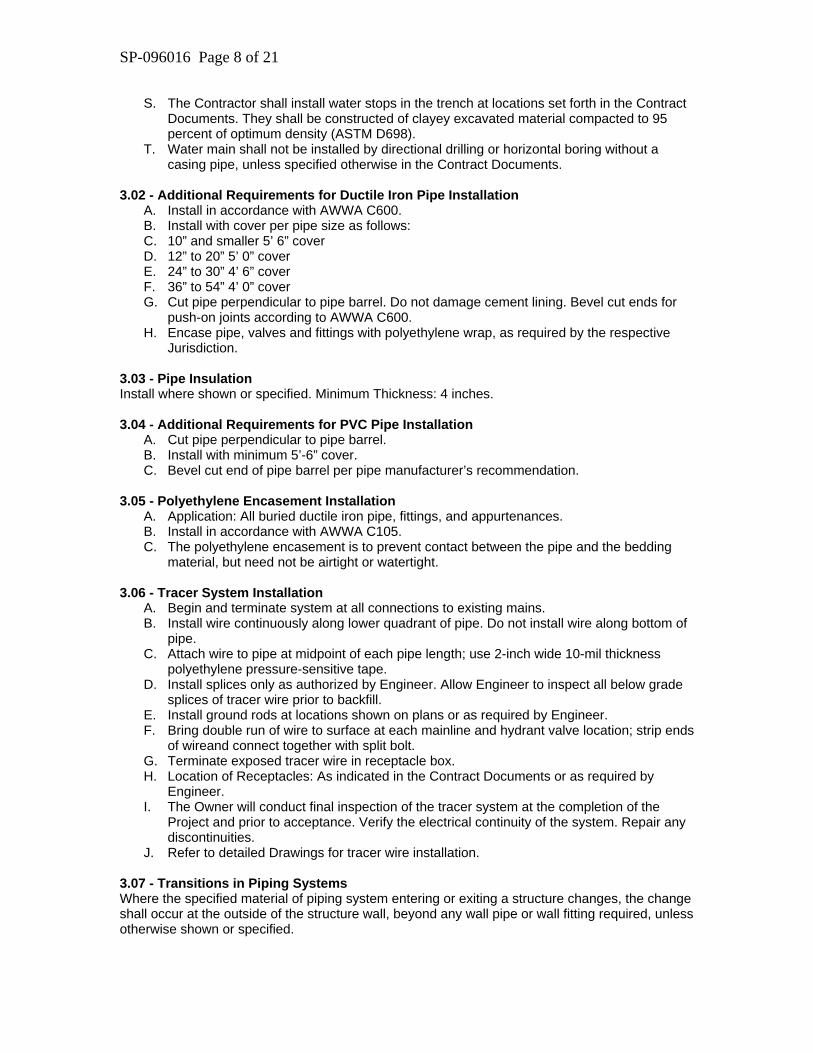
S. The Contractor shall install water stops in the trench at locations set forth in the Contract Documents. They shall be constructed of clayey excavated material compacted to 95 percent of optimum density (ASTM D698).
T. Water main shall not be installed by directional drilling or horizontal boring without a casing pipe, unless specified otherwise in the Contract Documents.
3.02 - Additional Requirements for Ductile Iron Pipe Installation
A. Install in accordance with AWWA C600. B. Install with cover per pipe size as follows: C. 10” and smaller 5’ 6” cover D. 12” to 20” 5’ 0” cover E. 24” to 30” 4’ 6” cover F. 36” to 54” 4’ 0” cover G. Cut pipe perpendicular to pipe barrel. Do not damage cement lining. Bevel cut ends for
push-on joints according to AWWA C600. H. Encase pipe, valves and fittings with polyethylene wrap, as required by the respective
Jurisdiction. 3.03 - Pipe Insulation Install where shown or specified. Minimum Thickness: 4 inches. 3.04 - Additional Requirements for PVC Pipe Installation
A. Cut pipe perpendicular to pipe barrel. B. Install with minimum 5’-6” cover. C. Bevel cut end of pipe barrel per pipe manufacturer’s recommendation.
3.05 - Polyethylene Encasement Installation
A. Application: All buried ductile iron pipe, fittings, and appurtenances. B. Install in accordance with AWWA C105. C. The polyethylene encasement is to prevent contact between the pipe and the bedding
material, but need not be airtight or watertight. 3.06 - Tracer System Installation
A. Begin and terminate system at all connections to existing mains. B. Install wire continuously along lower quadrant of pipe. Do not install wire along bottom of
pipe. C. Attach wire to pipe at midpoint of each pipe length; use 2-inch wide 10-mil thickness
polyethylene pressure-sensitive tape. D. Install splices only as authorized by Engineer. Allow Engineer to inspect all below grade
splices of tracer wire prior to backfill. E. Install ground rods at locations shown on plans or as required by Engineer. F. Bring double run of wire to surface at each mainline and hydrant valve location; strip ends
of wireand connect together with split bolt. G. Terminate exposed tracer wire in receptacle box. H. Location of Receptacles: As indicated in the Contract Documents or as required by
Engineer. I. The Owner will conduct final inspection of the tracer system at the completion of the
Project and prior to acceptance. Verify the electrical continuity of the system. Repair any discontinuities.
J. Refer to detailed Drawings for tracer wire installation. 3.07 - Transitions in Piping Systems Where the specified material of piping system entering or exiting a structure changes, the change shall occur at the outside of the structure wall, beyond any wall pipe or wall fitting required, unless otherwise shown or specified.
SP-096016 Page 9 of 21
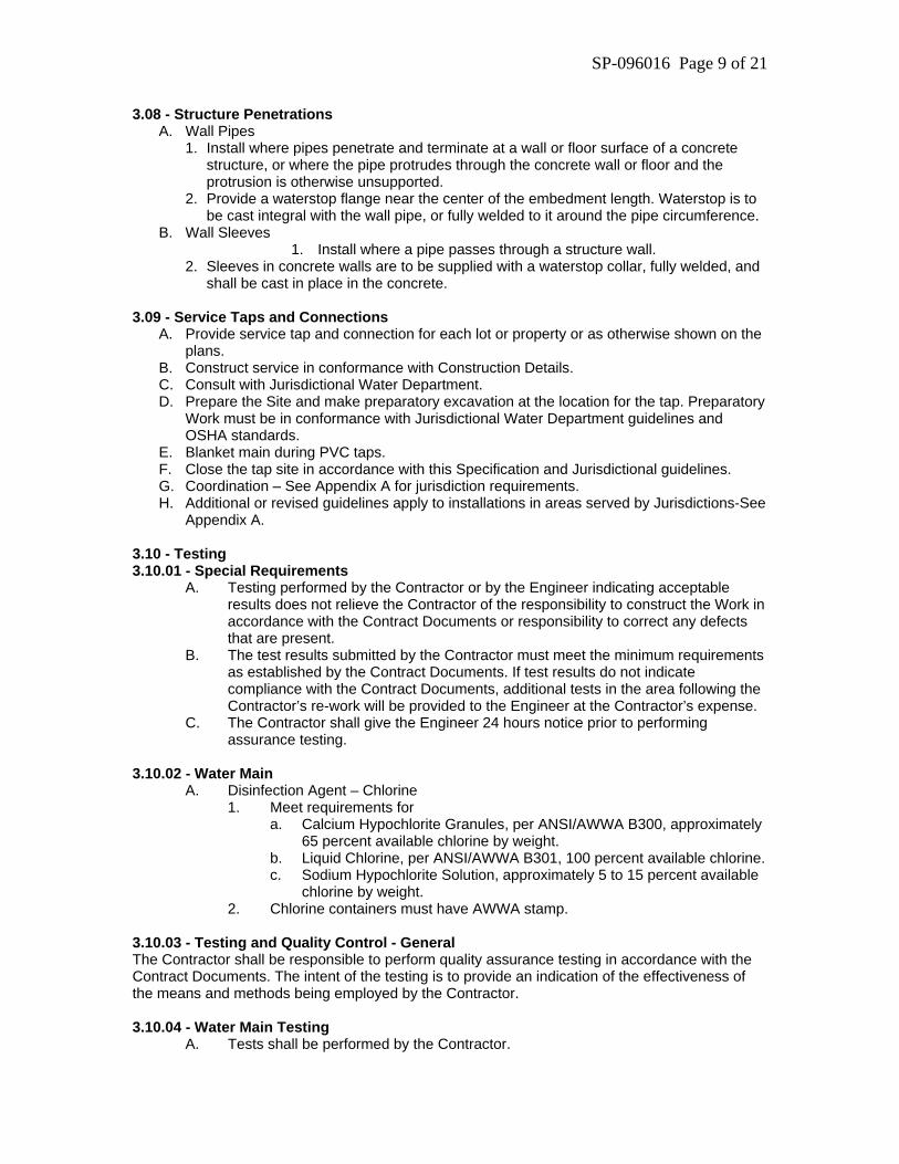
3.08 - Structure Penetrations A. Wall Pipes
1. Install where pipes penetrate and terminate at a wall or floor surface of a concrete structure, or where the pipe protrudes through the concrete wall or floor and the protrusion is otherwise unsupported.
2. Provide a waterstop flange near the center of the embedment length. Waterstop is to be cast integral with the wall pipe, or fully welded to it around the pipe circumference.
B. Wall Sleeves 1. Install where a pipe passes through a structure wall.
2. Sleeves in concrete walls are to be supplied with a waterstop collar, fully welded, and shall be cast in place in the concrete.
3.09 - Service Taps and Connections
A. Provide service tap and connection for each lot or property or as otherwise shown on the plans.
B. Construct service in conformance with Construction Details. C. Consult with Jurisdictional Water Department. D. Prepare the Site and make preparatory excavation at the location for the tap. Preparatory
Work must be in conformance with Jurisdictional Water Department guidelines and OSHA standards.
E. Blanket main during PVC taps. F. Close the tap site in accordance with this Specification and Jurisdictional guidelines. G. Coordination – See Appendix A for jurisdiction requirements. H. Additional or revised guidelines apply to installations in areas served by Jurisdictions-See
Appendix A. 3.10 - Testing 3.10.01 - Special Requirements
A. Testing performed by the Contractor or by the Engineer indicating acceptable results does not relieve the Contractor of the responsibility to construct the Work in accordance with the Contract Documents or responsibility to correct any defects that are present.
B. The test results submitted by the Contractor must meet the minimum requirements as established by the Contract Documents. If test results do not indicate compliance with the Contract Documents, additional tests in the area following the Contractor’s re-work will be provided to the Engineer at the Contractor’s expense.
C. The Contractor shall give the Engineer 24 hours notice prior to performing assurance testing.
3.10.02 - Water Main
A. Disinfection Agent – Chlorine 1. Meet requirements for
a. Calcium Hypochlorite Granules, per ANSI/AWWA B300, approximately 65 percent available chlorine by weight.
b. Liquid Chlorine, per ANSI/AWWA B301, 100 percent available chlorine. c. Sodium Hypochlorite Solution, approximately 5 to 15 percent available
chlorine by weight. 2. Chlorine containers must have AWWA stamp.
3.10.03 - Testing and Quality Control - General The Contractor shall be responsible to perform quality assurance testing in accordance with the Contract Documents. The intent of the testing is to provide an indication of the effectiveness of the means and methods being employed by the Contractor. 3.10.04 - Water Main Testing
A. Tests shall be performed by the Contractor.
SP-096016 Page 10 of 21
B. Scheduling 1. Notify Engineer one working day in advance of testing or disinfection
operations to coordinate the operations. 2. Engineer or his representative must be in attendance during testing or
disinfection. C. Regulatory Requirements: Conform to Iowa Department of Natural Resources
“Iowa Water Supply Facilities Design Standards.” D. Sequence of Operation
1. Perform operations in the following sequence: a. Remove any debris from within pipe. Clean and swab out pipe if
required. b. Secure any unrestrained pipe ends against uncontrolled movement. c. Fill the main and add chlorine. d. Wait 24 hours to check the chlorine content. Must be over 25 mg/l. e. Dispose of highly chlorinated water. f. Wait 24 hours for bacteriological testing and turbidity testing. g. Perform pressure and leak testing. h. Make taps after passing all tests.
2. Successfully complete each operation before commencing to the next operation.
3. Jurisdiction will provide reasonable quantities of water for flushing and testing.
E. Method Of Chlorination 1. The chlorination will be accomplished in accordance with AWWA
C651. The preferred method from that standard shall be the method utilizing HTH granules placed in the water main as it is being installed and then filling the main with potable water when installation is complete.
2. To utilize this method the pipes and appurtenances must be kept clean and dry during construction.
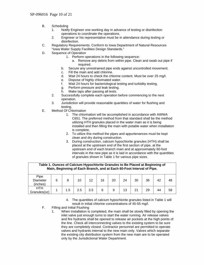
3. During construction, calcium hypochlorite granules (HTH) shall be placed at the upstream end of the first section of pipe, at the upstream end of each branch main and at approximately 60-foot intervals in the new pipe as it is laid in accordance with the quantities of granules shown in Table 1 for various pipe sizes.
Table 1. Ounces of Calcium Hypochlorite Granules to Be Placed at Beginning of
Main, Beginning of Each Branch, and at Each 60-Foot Interval of Pipe.
Pipe Diameter (inches)
6 8 10 12 16 20 24 30 36 42 48
HTH Granules(oz) 1 1.5 2.5 3.5 6 9 13 21 29 44 58
4. The quantities of calcium hypochlorite granules listed in Table 1 will
result in initial chlorine concentrations of 45-55 mg/l. F. Filling and Initial Flushing
1. When installation is completed, the main shall be slowly filled by opening the inlet valve just enough turns to start the water running. Air release valves and fire hydrants shall be opened to release air pockets at the high points of the line. Check all interconnecting valves to the existing system to be sure they are completely closed. Contractor personnel are permitted to operate valves and hydrants internal to the new main only. Valves which separate the existing city distribution system from the new main are to be operated only by the Jurisdictional Water Department.
SP-096016 Page 11 of 21
2. The chlorinated water shall remain in the pipe for at least 24 hours, during which time all valves and hydrants in the section treated shall be operated in order to disinfect the appurtenances. At the end of this 24-hour period, the disinfecting solution shall have a residual of not less than 25 mg/l as free chlorine.
3. After the completion of the 24-hour period, the heavily chlorinated water shall be flushed from the main until the chlorine concentration is less than 4 mg/l. A chlorine residual determination shall be made to ascertain that the chlorine concentration of the water in the new main is compatible with that in the city distribution system.
4. The Contractor shall furnish and install all hoses, equipment, and appurtenances necessary to direct the flushing water to the proper discharge point.
5. Highly chlorinated water shall be discharged to sanitary sewers. If sanitary sewers are not available in the area, the highly chlorinated water shall be trucked to a sanitary sewer, or neutralized by treating with one of the chemicals listed in Appendix B of AWWA C651. The rate of discharge to sanitary sewers shall be controlled to prevent surcharging the sewer. The Jurisdictional Sewer Department shall be contacted a minimum of 48 hours prior to discharge into the sanitary sewer.
G. Final Flushing 1. Once the chlorine content of the flushing water has declined to less than 4
mg/l as determined by the Jurisdictional Water Department, the water shall be directed to natural water ways or storm sewer intakes. The Contractor is responsible to direct the flushing water away from the Site in a safe and non-destructive manner. The Contractor shall continue flushing to remove debris and sediment from the new main until preliminary grab samples indicate that the turbidity has been reduced sufficiently to warrant samples to be taken for laboratory testing. In addition to the end of the new main, hydrants at intermediate points along the main and all blowoffs on branches shall be opened and flushed.
2. Where the water main consists of looped water mains, the Contractor shall develop a Plan, subject to prior approval of the Jurisdictional Engineer, for closing valves and flushing the loop to insure that all parts of the loop are flushed completely.
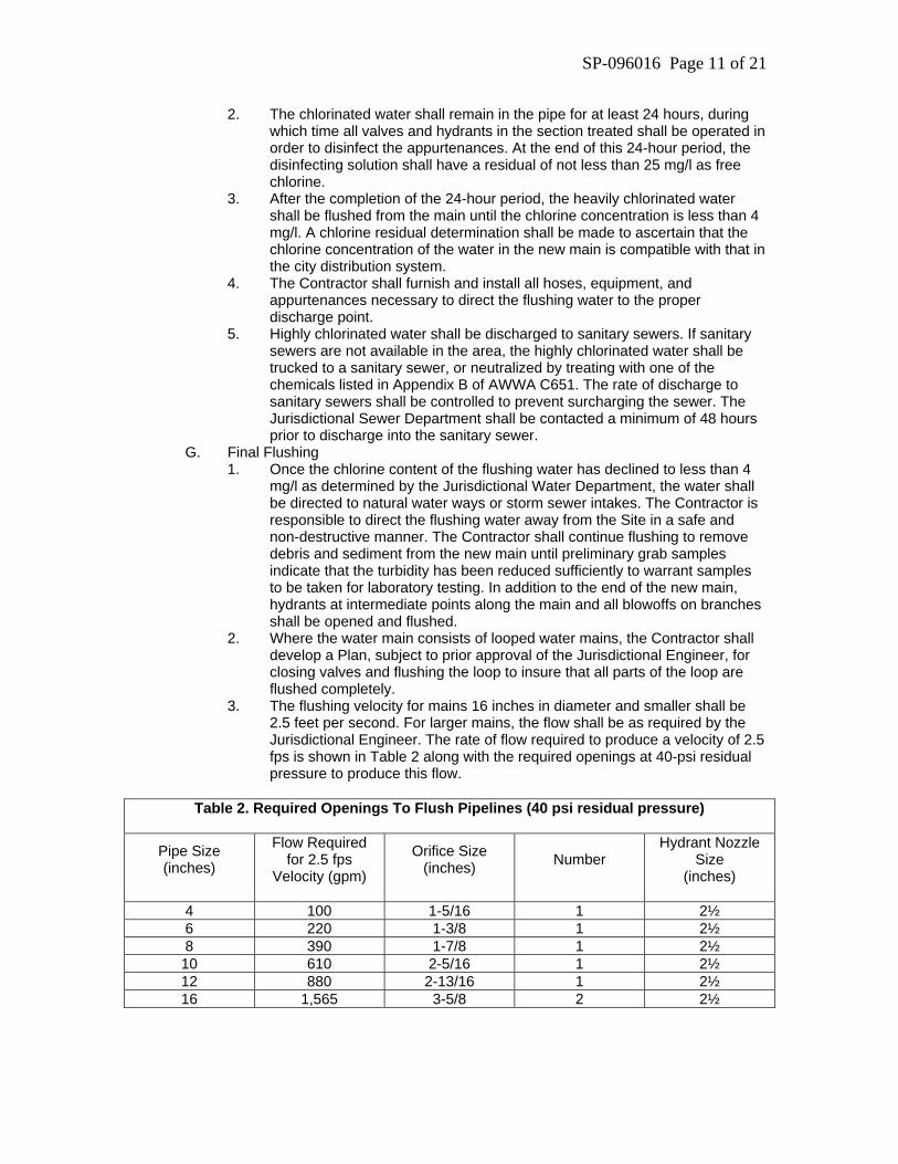
3. The flushing velocity for mains 16 inches in diameter and smaller shall be 2.5 feet per second. For larger mains, the flow shall be as required by the Jurisdictional Engineer. The rate of flow required to produce a velocity of 2.5 fps is shown in Table 2 along with the required openings at 40-psi residual pressure to produce this flow.
Table 2. Required Openings To Flush Pipelines (40 psi residual pressure)
Pipe Size (inches)
Flow Required for 2.5 fps
Velocity (gpm)
Orifice Size (inches)
Number
Hydrant Nozzle Size
(inches)
4 100 1-5/16 1 2½ 6 220 1-3/8 1 2½ 8 390 1-7/8 1 2½ 10 610 2-5/16 1 2½ 12 880 2-13/16 1 2½ 16 1,565 3-5/8 2 2½
SP-096016 Page 12 of 21
4. With 40-psi residual pressure, one 2½-inch hydrant nozzle will discharge approximately 1,000 gpm and a 4½-inch hydrant nozzle will discharge approximately 2,500 gpm.
H. Sampling Procedure: Once preliminary samples indicate that turbidity has been reduced sufficiently to warrant laboratory testing, samples shall be collected from blowoffs and hydrants at the end of the main, and at intermediate branches and hydrants. In the case of looped mains, valves shall be operated to insure that samples are drawn from all parts of the new main. Samples shall be collected by Jurisdictional Water Department personnel in sterile bottles treated with sodium thiosulfate as required by Standard Methods. No hose shall be used in the collection of samples.
I. Special Conditions: If, during construction, trench water has entered the main, or if in the opinion of the Engineer, excessive quantities of dirt or debris have entered the main, bacteriological samples shall be taken at intervals of approximately 200 feet and shall be identified as to location. Samples shall be taken of water that has stood in the main for at least 16 hours after final flushing has been completed.
J. Turbidity and Bacteriological Testing 1. Samples shall be tested by the Department for turbidity and bacteriological
quality in accordance with Standard Methods procedures. Turbidity shall be 1.0 ftu or less, and bacteriological tests shall show the absence of coliform organisms. A standard plate count may be required at the option of the Jurisdictional Engineer.
2. If satisfactory turbidity and bacteriological test results are obtained from the initial disinfection process, no further disinfection is required and the Contractor may proceed with pressure testing of the main.
3. If the test results are not satisfactory, further flushing and testing of the main is required.
K. Redisinfection: If the initial disinfection fails to produce satisfactory bacteriological samples, the main shall be reflushed and resampled. If check samples show the presence of coliform organisms, then the main shall be rechlorinated by the continuous feed or slug method of chlorination until satisfactory results are obtained.
L. Pressure and Leak Testing 1. Isolate new piping from the existing water system. 2. Fill and flush all new piping with potable water. Ensure that all trapped air is
removed. 3. Pressurize the new pipe to the test pressure at the highest point in the
isolated system. Do not pressurize to more than five psi over the test pressure at the highest point in the isolated system.
4. Test the completed piping system at 1½ times the system working pressure or 150 psi, whichever is greater, for two hours.
5. Monitor the pressure in the line for a period of not less than two hours. 6. If at any time during the test the pressure drops to five psi below the test
pressure, repressurize the pipe by pumping in potable water in sufficient quantity to bring the pressure back to the original test pressure.
7. Accurately measure the amount of water required to repressurize the system to the test pressure.
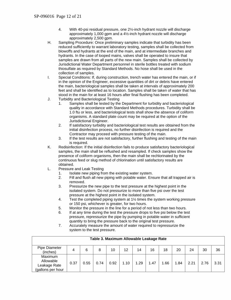
Table 3. Maximum Allowable Leakage Rate
Pipe Diameter
(inches) 4 6 8 10 12 14 16 18 20 24 30 36
Maximum Allowable
Leakage Rate (gallons per hour
0.37 0.55 0.74 0.92 1.10 1.29 1.47 1.66 1.84 2.21 2.76 3.31
SP-096016 Page 13 of 21
per 1,000 feet of pipe)
Note: For unusual conditions or for water lines shorter than 500 feet, consult Jurisdictional Engineer for allowable leakage rate. The following formula shall apply:
L = (S)(D)(P)½
133,200 Where: L = leakage, allowable S = length of pipe test section, in feet. D = pipe diameter, in inches. P = average test pressure, psig.
1. If the average measured leakage per hour exceeds the maximum allowable leakage rate, repair and retest the water line.
2. Repair all visible leaks regardless of the amount of leakage. B. Continuous Feed Method of Chlorination
1. Prepare a chlorine-water solution by dissolving granules of calcium hypochlorite in water in the proportion required for the desired concentration. A 1-percent chlorine solution requires approximately 1 pound of calcium hypochlorite in 8 gallons of water.
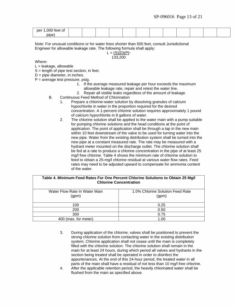
2. The chlorine solution shall be applied to the water main with a pump suitable for pumping chlorine solutions and the head conditions at the point of application. The point of application shall be through a tap in the new main within 10 feet downstream of the valve to be used for turning water into the new pipe. Water from the existing distribution system shall be turned into the new pipe at a constant measured rate. The rate may be measured with a hydrant meter mounted on the discharge outlet. The chlorine solution shall be fed at a rate to produce a chlorine concentration in the pipe of at least 25 mg/l free chlorine. Table 4 shows the minimum rate of chlorine solution to feed to obtain a 25-mg/l chlorine residual at various water flow rates. Feed rates may need to be adjusted upward to compensate for ammonia content of the water.
Table 4. Minimum Feed Rates For One Percent Chlorine Solutions to Obtain 25 Mg/l
Chlorine Concentration
Water Flow Rate In Water Main (gpm)
1.0% Chlorine Solution Feed Rate (gpm)
100 0.25 200 0.50 300 0.75
400 (max. for meter) 1.00
3. During application of the chlorine, valves shall be positioned to prevent the strong chlorine solution from contacting water in the existing distribution system. Chlorine application shall not cease until the main is completely filled with the chlorine solution. The chlorine solution shall remain in the main for at least 24 hours, during which period all valves and hydrants in the section being treated shall be operated in order to disinfect the appurtenances. At the end of this 24-hour period, the treated water in all parts of the main shall have a residual of not less than 10 mg/l free chlorine.
4. After the applicable retention period, the heavily chlorinated water shall be flushed from the main as specified above.
SP-096016 Page 14 of 21
C. Disinfection Procedures When Cutting Into Or Repairing Existing Mains 1. The following procedures apply primarily when mains are wholly or partially
dewatered. After the appropriate procedures have been completed, the main may be returned to service prior to completion of bacteriological testing in order to minimize the time customers are out of water.
2. Leaks or breaks that are repaired with clamping devices while the mains remain full of water under pressure present little danger of contamination and require no disinfection. a. Trench Treatment: When an old main is opened, either by accident or
design, the excavation will likely be wet and may be badly contaminated from nearby sewers. Liberal quantities of hypochlorite applied to open trench areas will lessen the danger from such pollution. Tablets have the advantage in such a situation because they dissolve slowly and continue to release hypochlorite as water is pumped from the excavation.
b. Swabbing with hypochlorite solution: The interior of all pipe and fittings used in making the repair (particularly couplings and sleeves) shall be swabbed or sprayed with a one percent hypochlorite solution before they are installed.
c. Flushing: Thorough flushing is the most practical means of removing contamination introduced during repairs. If valve and hydrant locations permit, flushing toward the
D. Work location from both directions is recommended. Flushing shall be started as soon as the repairs are completed and shall be continued until discolored water is eliminated.
E. Putting Water Main In Service: Obtain Jurisdictional Engineer’s approval to put the completed water system in service.
3.11 - Flushing
A. Method of flushing is subject to prior approval of Engineer. Flush in accordance with approved method under the supervision of the Engineer. Refer to Section 3.10 Testing.
B. Disinfection: According to Section 3.10 Testing. 3.12 - General Requirements For Installation Of Valves And Appurtenances
A. Install only approved materials. B. Install in accordance with the Contract Documents, the Construction Details, and the
Engineer’s instructions, as appropriate. C. Test and disinfect all valves, hydrants and appurtenances as components of the
completed water main in accordance with Section 3.10 Testing. D. Apply polyethylene wrap to all valves, valve boxes, hydrants and fittings. E. Set tops of valve boxes to finish grade in paved areas and 2 inches below finish grade in
nonpaved areas unless otherwise directed by Engineer. F. Check the working order of all valves by opening and closing through entire range.
3.13 - Flushing Device (Blowoff)
A. Install where shown on the plans, in accordance with Construction Details. B. Install gravel backfill. C. Install thrust block, bearing on perpendicular excavation face of undisturbed earth.
3.14 - Fire Hydrant
A. If auxiliary valve is positioned adjacent to water main, attach it to anchoring tee. B. If auxiliary valve is positioned away from water main, restrain all joints between valve and
water main. C. Fire hydrant depth setting:
SP-096016 Page 15 of 21
1. Use adjacent finish grade to determine setting depth. If finish grade is not to be obtained during the current Project, consult with Jurisdiction Engineer for proper setting dimension.
2. Not lower than manufacturer’s minimum setting dimension, and not lower than 18 inches, measured from nozzle to grade.
3. Refer also to Fire Hydrant Tables, Appendix C of this section. D. Coordinate installation with tracer wire installation. E. Refer to Construction Details according to Special Provisions in Appendix A. F. Tee, isolation valve, and associated piping (but NOT barrel) shall be wrapped with
polyethylene sheeting. G. Hydrant extensions will not be allowed. If possible, adjust height by deflection of joints; if
necessary, adjust height by use of fittings. 3.15 - Required Separations of Water Mains, Sanitary Sewers, and Storm Sewers
A. General: The following specifications are derived from the 1997 edition of the 10 State B. “Recommended Standards for Water Works.” Updates to the 10 States Standards, by
reference C. herein, shall also apply to these specifications. D. The following factors should be considered in providing adequate separation:
1. Materials and types of joints for water and sewer pipes. 2. Soil conditions. 3. Service and branch connections into the water main and sewer line. 4. Compensating variations in the horizontal and vertical separations. 5. Space for repair and alterations of water and sewer pipes. 6. Off-setting of pipes around manholes.
E. Parallel installation: Water mains shall be laid at least 10 feet horizontally from any existing or proposed sewer or septic tank absorption field trench. The distance shall be measured edge to edge. In cases where it is not practical to maintain a 10-ft separation, the reviewing authority may allow deviation on a case-by-case basis, if supported by data from the design engineer. Such deviation may allow installation of the water main closer to a sewer, provided that the water main is laid in a separate trench or on an undisturbed earth shelf located on one side of the sewer at such an elevation that the bottom of the water main is at least 18 inches above the top of the sewer.
F. Crossings: Water mains crossing sewers shall be laid to provide a minimum vertical distance of 18 inches between the outside of the water main and the outside of the sewer. This shall be the case where the water main is either above or below the sewer with preference to the water main located above the sewer. At crossings, one full length of water pipe shall be located so both joints will be as far from the sewer as possible. Special structural support for the water and sewer pipes may be required.
G. Exception: The reviewing authority must specifically approve any variance from the requirements of paragraphs C and D of this section when it is impossible to obtain the specified separation distances. Where sewers are being installed and these paragraphs cannot be met, the sewer materials shall be waterworks-grade 150-psi pressure-rated pipe or equivalent and shall be pressure-tested to insure watertightness.
H. Force mains: There shall be at least a 10-ft horizontal separation between water mains and sanitary sewer force mains. There shall be an 18-inch vertical separation at crossings as required in paragraph D above.
I. Sewer manholes: No water pipe shall pass through or come in contact with any part of a sewer manhole.
3.16 - Service Taps
A. Made at ten o’clock or two o’clock position unless corporation would have less than five feet of cover. When five feet of cover is not available, tap may be rotated downward no farther than midpoint of pipe. Taps shall be no closer than 18 inches apart and staggered around the circumference of pipe.
SP-096016 Page 16 of 21
B. Taps on A-C pipe: purge valve of tapping machines opened so chips will be flushed from pipe.
C. Tapping saddle is required for taps 1½ inches and larger, on mains 4 inches or smaller, and on PVC pipe.
3.17 - Water Main Abandonment
A. Water mains must be abandoned in place by using mechanical devices manufactured specifically for such purposes to completely seal the ends of the pipe.
B. Mechanical joint plugs or mechanical joint caps with watertight gaskets must be installed at the termination points of the abandoned water main.
C. Specially fabricated, watertight gaskets are required at the request of the Owner where water main exists in contaminated soil areas.
D. Oversized mechanical joint caps or plugs may be required depending upon the outside diameter of the existing water pipe.
E. The Contracting Authority may require the existing water main to be removed from the ground in lieu of abandonment “in place”. Unless such removal is called for on the drawings or in the Special Provisions, a change order to the contract price will be negotiated.
F. Remove valve boxes on valves on abandoned mains to a minimum of one foot below top of grade in unpaved areas, or to bottom of sub-grade in paved areas.
G. Fill remainder of valve box and excavation with sand to a minimum of one foot below grade in unpaved areas, or to bottom of sub-grade in paved areas.
3.18 - Water Service Line Abandonment
A. The Contractor shall disconnect water service at the main. The location of mains, where known, will be provided by the local jurisdiction. The Contractor may be required to schedule excavations in certain streets in accordance with the requirements of the local jurisdiction. Methods of Work on mains and services will be subject to prior approval and inspection by the Engineer. The work shall be subject to approval by the Engineer prior to backfilling.
B. Those water services controlled by a corporation stop on the main shall be disconnected at the main by closing the corporation stop and disconnecting the service line. A cap or corporation nut shall be installed on the corporation stop. Upon completion of a water service disconnect, and inspection of the same, the Contractor shall backfill the excavation. The backfill shall be compacted to 95 percent of the Standard Proctor Density as set forth in ASTM D698.
C. Curb stops and risers must be completely removed from all abandoned service lines. The remaining service line must be terminated in the following fashion:
D. Copper: Install a copper cap using a silver soldering method. E. Lead: Flatten a minimum of 8 inches of lead pipe end, fold a minimum of 2 inches of
flattened end back 180 degrees, then re-flatten forming a folded seal on the tail of the lead service line material.
F. All service lines larger than 2 inch, or manufactured from materials other than copper or lead, must be terminated at a point closest to the water main. Tapping valves shall be removed from its associated tapping sleeves. A blind flange shall be installed on the tapping sleeve, where possible, after the tapping valve is removed.
G. If a blind flange cannot be installed, then one of the following methods of abandonment must be used at the direction of the Owner: 1. The tapping sleeve must be cut out of the water main and a new spigot piece of water
pipe must be inserted in its place. 2. A cast iron split repair sleeve shall be installed on the water main to seal the tapped
opening in the pipe. 3. A full body cast iron tapping sleeve with blind flange shall be installed on the water
main to seal the tapped opening in the pipe. 4. Unless one of these approaches is called for on the drawings or in the Special
Provisions, a change order to the contract price will be negotiated.
SP-096016 Page 17 of 21
H. Service lines that are terminated at a tee must be sealed by installing a mechanical plug, cap, or flange, at the outlet of the tee. If this method of abandonment is not possible then at the Contracting Authority’s direction the tee must be cut out of the water main and a new spigot piece of pipe must be inserted in its place. Unless this approach is called for on the drawings or in the Special Provisions, a change order to the contract price will be negotiated.
PART 4 METHOD OF MEASUREMENT 4.01 - Section Includes
Measurement and payment criteria applicable to the Work by the Contractor.
4.02 - Authority The Engineer will be responsible to verify measurements for payment as submitted by the Contractor with the request for payment. Any discrepancies between the quantity submitted by the Contractor and the quantity measured by the Engineer will be decided by the Engineer.
4.03 - Measurement and Payment Descriptions
A. The following shall be considered incidental to bid items; unless a bid item appears. Items considered incidental are not limited to those listed here: 1. Submittals. 2. Finish grading. 3. Trench excavation and backfill with suitable native material. 4. Sheeting, shoring and bracing. 5. Bedding. 6. Dewatering. 7. Measures required to protect subgrades. 8. Measures required to provide positive drainage during construction. 9. Measures required to protect existing features including existing utilities, of
the project site. B. Itemized Sections (see following sections.)
4.04 – Itemized Sections Water Main, Trenched: paid on a lineal basis, not including fittings, for each type and size as set forth in the Contract Documents, as measured by the Engineer. Polyethylene wrap and tracer wire are incidental. Fittings by Weight, DIP: paid on a weight basis. The quantity paid shall be fittings as counted by the Engineer and converted to a weight basis in accordance with standard fitting weights as published in AWWA C153. Nuts bolts, retainer glands, and restraining rods are incidental. Valve, Gate: paid on a count basis for each type and size as set forth in the Contract Documents, as counted by the Engineer. Polyethylene wrap, other piping materials required for installation, and adjustment to finished grade are incidental. Fire Hydrant Assembly: paid on a count basis for each type and size as set forth in the Contract Documents. The quantity paid shall be as indicated in the Contract Documents. Hydrant gate valve, mainline tee, valve box, material delivery, other piping materials required for installation, and rotating hydrant for proper direction of nozzles are incidental. Flushing Device (Blowoff), As Per Plan: paid on a count basis for each type and size as set forth in the Contract Documents. The quantity paid shall be as indicated in the Contract Documents. Polyethylene wrap and other piping materials required for installation are incidental.
SP-096016 Page 18 of 21
Disinfection and Hydrostatic Testing: paid on a lump sum basis. This item includes furnishing all materials, labor, and equipment to disinfect the water main and re-disinfect if required, and perform the hydrostatic testing of the completed water main; including corporation stops, copper tubing, hoses, pumps, gauges and other equipment required for disinfection and hydrostatic testing. Also included are hoses, piping and accessories necessary to conduct the chlorinated water to a proper disposal point. PART 5 BASIS OF PAYMENT 5.01 - Payment
A. Payment for the Work completed in accordance with the Contract Documents will be measured and paid as described below or in the Contract Documents, only if the bid item appears on the bid form.
B. If, in the completion of the Work, the quantities for measured items vary from those on the bid form, the Contractor shall report the discrepancy to the Engineer before the work is covered. In such a case, the payment to the Contractor shall be adjusted based on the unit prices submitted on the bid form. However, if the Engineer determines the character of the additional quantity is not consistent with the character of the item(s) upon which the unit price is based, a different unit price may be negotiated.
C. The Contract Price for any item shall be full compensation for completion of the item, including any materials, equipment, tools, and labor necessary to complete the item in accordance with the Contract Documents.
D. If no bid item appears on the bid form, related work shall be considered incidental to a bid item and no additional payment will be made for the requirement.
5.02 – Itemized Sections Water Main, Trenched: For the number of lineal feet of water main of each size and type furnished and installed, the Contractor shall be paid the contract unit price. Fittings by Weight, DIP: For the number of pounds of water main fittings furnished and installed, the Contractor shall be paid the contract unit price. Valve, Gate: For the number of gate valves plus valve boxes of each type and size furnished and installed, the Contractor shall be paid the contract unit price. Fire Hydrant Assembly: For the number of fire hydrant assemblies furnished and installed, the Contractor shall be paid the contract unit price. Flushing Device (Blowoff), As Per Plan: For the number of blowoff assemblies furnished and installed, the Contractor shall be paid the contract unit price. Disinfection and Hydrostatic Testing: Disinfection and hydrostatic testing will be measured and paid for at the lump sum contract price.
END OF SECTION, EXCEPT APPENDICES
SP-096016 Page 19 of 21
APPENDIX A-2 SECTION 02500 SPECIAL PROVISIONS MARION 2.01 – Water Mains
A. Ductile Iron Pipe 4. Minimum Thickness Class: DELETE letters b, c, and d and SUBSTITUTE the
following over 12 inch; Class 50 per ANSI/AWWA C151/A21.51. 2.06 – Pipe Line Accessories
A. Polyethylene Wrap ADD THE FOLLOWING: 3. Use polyethylene wrap on all fittings and valves in buried service.
B. Tracer System 7. Delete receptacle box; replace with One Piece VALVCO Tracer Wire Access Box or equal (Box will be supplied and billed with the hydrant assembly and installed by all new hydrants.)
2.08 – Valves
A. General ADD THE FOLLOWING: 9. Open when turned left.
C. Gate Valves, Buried Service ADD THE FOLLOWING: 12. Open when turned left. 13. Body, bonnet, and operating hold down bolts and nuts to be SS. 14. Operating nut to be attached to valve stem by bolt or nut type connection. 15. Valve stem shall be removable without removing valve bonnet.
D. Tapping Valve Assemblies ADD THE FOLLOWING: 1. Tapping valve shall conform to ANSI/AWWA C509 and C515. 6. Tapping Sleeves on PVC
a. Stainless steel b. Approved sleeves: Romac SST, Mueller 304 SS, or approved equal.
7. Tapping sleeve shall be tested prior to tapping, in accordance with department rules. 3.09 – Service Taps and Connections ADD THE FOLLOWING:
F. Coordination 5. Water main to be in service and all tests passed prior to ordering taps. 6. Lot pins to be placed prior to making tap. 7. Call at least 24 hours ahead of need for taps for all taps.
G. Additional Guidelines 1. Taps 2 inches and smaller are made by the Marion Water Department. 2. Taps larger than 2 inches shall be made by the Contractor.
3.14 – Fire Hydrant
E. Construction Details ADD THE FOLLOWING: 1. Hydrant set perpendicular to Main – see plan details.
END OF APPENDIX A-2
SP-096016 Page 20 of 21
APPENDIX B SECTION 02500 APPROVED SERVICE LINE MANUFACTURERS AND MODEL NUMBERS B.01 - Corporation Stop.
A. Marion approved manufacturer and model numbers: 1. Mueller H-15000 2. Mueller 4701
B.02 - Curb Stop
A. Marion approved manufacturers and model numbers: 1. Mueller H-15204 2. AY McDonald 6100
B.03 - Curb Box
A. Marion approved manufacturers and model numbers: 1. Mueller H-10334 2. AY McDonald 5607
B.04 - Tapping Saddles
A. Marion approved manufacturer and model number: 1. Smith Blair Model 317
END OF APPENDIX B
SP-096016 Page 21 of 21
APPENDIX C SECTION 02500 APPROVED FIRE HYDRANT MANUFACTURERS AND MODEL NUMBERS B.01 – Acceptable Manufacturers
A. Marion approved manufacturer and model numbers: 1. Mueller Super Centurion 200
B.02 - Hydrant Characteristics Main Valve Size 5¼ inch Inlet Connection Type 6-inch flanged Direction of Opening Left Pumper Nozzle Size 4½ inch Pumper Nozzle Thread 5.7659" Diameter National Standard Thread Hose Nozzle Number/Size 2 ea. - 2½ inch Hose Nozzle Thread 3.078" OD Male, 3.140" OD Female 6 tpi Operating Nut 1¼-inch pentagon Nominal Bury Depth 6’-0” Remarks Word "OPEN" and arrow to be cast on top. Two coats of fire
hydrant red paint. Dry top design with provision for lubricating operating mechanism. Bronze-bronze seat/seat ring. Weather cap for operating nut.
END OF APPENDIX C