Embed Size (px)
Citation preview

“ME6”“ME6”EQUIPOS PREFABRICADOS Y MODULARES, METAL ENCLOSED,
EQUIPADOS CON DESCONECTADORES AISLADOS EN SF6, TIPO IMSEQUIPOS PREFABRICADOS Y MODULARES, METAL ENCLOSED,
EQUIPADOS CON DESCONECTADORES AISLADOS EN SF6, TIPO IMS
MV METALENCLOSED MODULAR PANELS EQUIPPED WITH SF6 SWITCHDISCONNECTORS
MV METALENCLOSED MODULAR PANELS EQUIPPED WITH SF6 SWITCHDISCONNECTORS

22 \ 2522 \ 25
1
5
7
8
9
10
11
12
13
14
15
16
17
18
19
21
26
31
34
36
39
Características generales
Tipos estandarizados
- Celda entrada/ remonte de barras “AC”
- Celda entrada de cables sobre barras “RC”
- Celda entrada/ salida con Seccionador “L3/L5”
- Celda Protección Transformador “F3/F5”
- Celda Protección General “ PG” condisyuntor en SF6 o Vacío
- Celda de Medición “ARSM”
- Celda de Medición “ARSM-B”
- Celda de Medición “ARSM-B1”
- Celda de Medición “ARSM-B2”
- Celda de Medición “ARSM-B3”
-Celda Protección General “PG+Remonte” condisyuntor en SF6 o Vacío y Celda de Remonte
- Celda de Medida “SM3/SM5”
- Celda para Montaje de transformador “AT”
Características de los componentes
- Interruptor de maniobra y seccionador SD6/L
- Interruptor de maniobra y seccionador confusibles SD6/F
- Seccionador D6
- Seccionador de puesta a tierra ST
Tipos de mecanismos de operación
Fundaciones y fijación al pavimento
General characteristics
Standard types
- Incoming and bus riser unit “AC”
- Cable riser “RC”
- Incoming/outgoing unit “L3/L5”
- Transformer protection unit “F3/F5”
- General protection unit “PG” withSF6/Vacuum circuit-breaker
- Measurement unit “ARSM”
- Measurement unit “ARSM-B”
- Measurement unit “ARSM-B1”
- Measurement unit “ARSM-B2”
- Measurement unit “ARSM-B3”
- General protection unit with SF6/vacuumcircuit-breaker and bus riser panel“PG+RISER”
- Measurement unit “SM3/SM5”
- Transformer housing unit “AT”
Characteristics of components
- Switch-disconnector type SD6/L
- Switch-disconnector type SD6/F equipped withfuses
- Disconnector type D6
- Earthing switch type ST
Operation mechanism types
Fixing to floor and foundation
1
5
7
8
9
10
11
12
13
14
15
16
17
18
19
21
26
31
34
36
39
22 \ 25
INDICE pag. INDEX page
ELETTROMECCANICA ADRIATICA S.p.A. se reserva el derechode llevar eventualmente a cabo, sin ningún aviso previo, cualquiermodificación que estime necesaria para mejorar y alcanzar nuevosrequerimientos técnicos y/o de construcción. Por lo tanto, lascaracterísticas e ilustraciones de esta publicación están al día hasta lafecha de impresión de este catálogo.
ELETTROMECCANICA ADRIATICA reserves the right to carry out,without any prior notice, any modifications it deems necessary inorder to improve and meet any construction requirement. Therefore,the data and illustrations in this publication are updated up to thepoint of approval for printing.

Los tableros en media tensión ME6, aislados en SF6, fueronestudiados para ser usados como celdas de distribuciónsecundaria en MT y diseñados para proporcionar una ampliavariedad de funciones y servicios requeridos por los modernossistemas de distribución.El tablero se forma utilizando unidades típicas estandarizadas.Durante la etapa de diseño, se tomó en consideración lafuncionalidad, la simplicidad de los dispositivos de maniobray de los enclavamientos, sin que tengan necesidad demantenimiento por un largo periodo de tiempo.Cada unidad típica está dividida en dos compartimientos, unoencima del otro: Compartimiento superior conteniendo el sistema de barras
principales; Compartimiento inferior conteniendo varios equiposeléctricos de interrupción y seccionamiento, de protección,transformadores de corriente y de tensión y terminales.
Los compartimientos están segregados uno del otro por elinterruptor-seccionador IMS, de cuerpo metálico, quegarantiza una protección IP3X. Esto permite que cuando lapuerta está abierta y las barras superiores energizadas, elacceso al compartimiento de equipos queda accesible sinriesgo.
En la parte superior de la Celda (en el compartimiento de BajaTensión) es posible montar una sección de BT para instalarvarios equipos de BT.
The SF6-insulated M.V. ME6 switchboards have been studiedfor M.V. secondary distribution compact stations and theyhave been designed to provide a wide variety of functions andservice as required by modern power distribution system.The switchboard is realized with standardized typical units.During the design stage of the units we took intoconsideration the functionality, the simplicity of operation andlocking devices and a long period of service without anymaintenance.Each typical unit is divided into two compartments placed oneon the top of the other: an upper compartment containing the main bus-bars; a lower compartment containing various electrical
equipment (circuit-breakers, isolators, protections,current transformers, voltage transformers andterminals).
The compartments are segregated from each other with theswitch-disconnector metal body which guarantees an IP3Xprotection degree, and when the door is open and the bus-bars are in service, the access into the equipmentcompartment is allowed.In the superior position (on the busbars compartement) it ispossible to locate a LV section for various LV electricalequipments.
CARACTERISTICAS GENERALESGENERAL CHARACTERISTICS

El tablero ME6 presenta las siguientes características:A) Máxima seguridad para el personal gracias a: Puesta a tierra de toda la estructura y de la segregación
metálica entre los compartimientos; Enclavamientos mecánicos que aseguran una secuencia de
operaciones exacta; Grado de protección IP3X para el gabinete exterior; A prueba de arco interno 16 kA – 1”.B) Seguridad contra la propagación del fuego:La total segregación metálica entre compartimientos y el usode materiales auto-extinguibles previenen la propagación delfuego.C) Facilidad de operación:Todas las operaciones de comando se efectúan desde el frentedel tablero por medio de dispositivos simples y funcionales,provistos de señalizaciones mecánicas que indican el estadode los componentes.Al frente del tablero se encuentran claras Instrucciones deOperación.D) VersatilidadPosibilidad de diferentes aplicaciones técnicas.Largos frontales de 375-500-750mm (a prueba de arco internoa pedido).E) Larga vida útil en base a una elección cuidadosa de
los materiales: El color estándar es gris RAL 7035. Otros colores a
pedido.
The main aspects of ME6 switchboards are as following:A) Maximum safety for personnel thanks to: Earthing of both the whole switchboard structure and
the metal division between the compartments; Mechanical interlocks which assure the exact
operation sequence; IP3X protection degree on the external housing; Internal arc proofed 16 kA – 1”.B) Protection against the spread of fire:The metal segregation of the compartments and the use ofself-extinguishing insulating materials prevent the spreadingof fire.C) Easy operation:All the various operations are carried out from the front of theswitchboard by means of simple and functional devices,provided with mechanical signals indicating the position ofthe components.Clear operation instructions on the front of the switchboard.D) VersatilityAll different technical applications.Esecution width 375-500-750 mm (Internal arc tested onrequest).E) Long functional life throught careful choice of
materials: Standard colour: grey RAL 7035 (other colours on
request).

FEATURES AND APPLICATION RANGESThe ME6 swicthboard is made of a modular units(Switchboards) with SD6 Switch-disconnectorcompletely SF6 insulated.It’s possible to use standard cable glands (indoor use).The most important application ranges of the ME6switchboards are the following: public secondary distribution industrial distribution
SWITCH-DISCONNECTOR FEATURESThe SD6 swicth-disconnector is compact type and lowvolume of SF6 insulation.The metallic body makes the segregation betweenterminal cable box and busbar with high safe degree.Inside there is an earthing switch with making capacity.The operating mechanism is very reliable and it ispossible to have hand or motorized system.
CARACTERISTICAS Y CAMPO DEAPLICACIONEl tablero ME6 está formado por unidades modularescompartimentadas que utilizan un desconectador tipoIMS tipo SD6, completamente aislado en SF6.Es posible usar mufas estándar para uso interior.El campo de aplicación del tablero ME6 esfundamentalmente el siguiente: Distribución Secundaria Pública. Distribución Industrial.
CARACTERISTICAS DEL DESCONECTADORIMSEl interruptor de maniobra SD6 es del tipo compactocon aislación de bajo volumen en SF6.La envolvente metálica forma la segregación entre losterminales y las barras con un alto grado de seguridad.Dentro del desconectador existe un seccionador depuesta a tierra con poder de cierre.El mecanismo de operación es extremadamenteconfiable y es posible tener una versión de operaciónmanual y/o motorizada.
Tensió nominalRated voltageFrecuencia nominalRated nominal frequancyTensión de prueba por 1 min. 50 Hz entre tierra y entre fasesTest voltage 1 min. 50 Hz against earth and between the phasesTensión de prueba por 1 min. 50 Hz entre los contactos abiertos del seccionador IMSTest voltage 1 min. 50 Hz between the open contacts of the switch-disconnectorTensión de Impulso entre tierra y entre fasesImpulse withstand voltage against earth and between the phasesTensión de Impulso entre los contactos abiertos del seccionador IMSImpulse withstand voltage between the open contacts of the switch-disconnectorCorriente nominalRated currentCorriente nominal de las barrasBus-bar rated currentCorriente admisible nominal de breve duración (1 sec.)Rated short-time withstand current (1 sec.)Corriente admisible nominal de breve duración (3 sec.)Rated short-time withstand current (1 sec.)Valor de cresta de la corriente admisible nominalRated peak withstand currentArco interno – CEI EN 62271-200 app. A-A (Acceso de tipo A - criterio del 1 a 6)Internal arc – CEI EN 62271-200 app. A-A (Access. type A - criteria 1 to 6) 16/1' (**) 16 /1' (**) 16 /1' (**)
31,5-65 31,5-6531,5-65
[kA]
[kA]
[kA]
[kA]
[kV]
[A]
[A]
[A]
[kV]
[Hz]
[kV]
[kV]
12
28
32
75
50/60
24
38 50
45 60
50/60 50/60
17,5
12,5/21 12,5/2112,5/21
110
400/630
400/630/800
85
400/630
12,5/25*
* 25 kA-2 sec. a pedido
* 25 kA-2 sec. on request(**) Valores mayores a pedido(**) Bigger values on request
VALORES NOMINALES / RATED VALUES
95
12,5/25* 12,5/25*
400/630
400/630/800400/630/800
145
125

Due to the continuous development of Standardsas well as of materials, the characteristics anddimensions indicated in this catalogue must beregarded as binding only on our confirmation.
Debido al continuo desarrollo de los Estándaresasí como también de los materiales, lascaracterísticas y las dimensiones indicadas eneste catálogo deben ser consideradas válidasdespués de nuestra confirmación.
QUALITY SYSTEMThe designing and manufacturing system iscarried out with a rigid application of theCompany Quality System, certified by CSQ(EQNET Member), in compliance with ISO9001-2000 Standards.
SISTEMA CONTROL DE CALIDADEl sistema de diseño y manufactura se lleva acabo aplicando rígidamente el Sistema deControl de la Calidad de la Compañía,certificado por CSQ (miembro de EQNET)según la normativa ISO 9001-2000
TEST REPORTSME6 cubicles have successfully passed all thetype tests requested by the international andnational Standards (IEC, CEI, ChineseStandard GB 3804-90, GOST Russia) inofficially acknowledged testing laboratories.
Norme InternazionaliIEC 60265, 62271-200, 62271-102, 60694
Other StandardsItalian CEI EN 62271-200 StandardsENEL Homologation to Spec. DY 803/1/2/4Italian accident prevention law (D.P.R. 547)
REPORTES DE PRUEBASLos cubículos de la serie ME6 han pasadoexitosamente todas las pruebas requeridaspor las Normas Internacionales y Nacionales(IEC, CEI, Chinas GB 3804-90, Rusas GOST)en laboratorios oficialmente homologados.
Norma InternacionalIEC 60265, 62271-200, 62271-102, 60694
Otras NormasNorma Italiana CEI EN 62271-200Homologación ENEL DY803/1/2/34Ley Italiana de Prevención de Accidentes
(D.P.R. 547)
ENVIROMENTThe Quality System is integrated with anEnviromental policy that is of primaryimportance for our company.Enviromental Management Systems is certified byCSQ ( EQNET member) in compliance with ISO14001-2004 standard.
GESTION AMBIENTALEl Sistema de Calidad está integrado a unapolítica del Medio Ambiente que es deimportancia primaria para nuestra compañía.El sistema de Gestión Ambiental estácertificado por CSQ (miembro de EQNET)según la normativa ISO 14001-2004.
SERIE ME6SERIE ME6ME6 SERIES
REFERENCIA NORMATIVA STANDARDS

CELDA PROTECCION DETRANSFORMADOR “F3/F5”
CELDA DE PROTECCION GENERAL “PG” CON DISYUNTOR EN SF6 O VACIO
CELDA DE ACOMETIDA y/o SALIDA CONINTERRUPTOR-SECCIONADOR “L3/L5”
CELDA DE ACOMETIDA y/o SALIDACON BARRAS “AC”
CELDA DE ACOMETIDA CON CABLES“RC”
INCOMING/OUTGOING “L3/L5”INCOMING AND BUS RISER UNIT “AC”CABLE RISER UNIT “RC” TRANSFORMER PROTECTION UNIT“F3/F5”
GENERAL PROTECTION UNIT “PG” WITH SF6/VACUUM CIRCUIT-BREAKER
TIPOLOGIA ESTANDARSTANDARD TYPES
CELDA DE MEDICION “ARSM”
MEASUREMENT UNIT “ARSM”
CELDA DE MEDICION “ARSM-B”
MEASUREMENT UNIT “ARSM-B”
CELDA DE MEDICION “ARSM-B1”
MEASUREMENT UNIT “ARSM-B1”

CELDA DE MEDICION “ARSM-B2” (conexión con barras)
MEASUREMENT UNIT “ARSM-B2” (Bus Coupler)
CELDA DE MEDICION “ARSM-B3”
MEASUREMENT UNIT “ARSM-B3”
CELDA PARA EL MONTAJE DE UN TRANSFORMADOR “SAT”
HOUSING TRANSFORMER UNIT “SAT”
CELDA DE PROTECCION GENERAL CON DISYUNTOR EN SF6 y/o VACIO YREMONTE CON BARRA “PG+RISER”
GENERAL PROTECTION UNIT WITH SF6/VACUUM CIRCUIT-BREAKER AND BUS RISER“PG+RISER”
CELDA DE MEDICION “SM3/SM5”
MEASUREMENT UNIT “SM3/SM5”

CELDA DE ACOMETIDA y/o SALIDA CON BARRASINCOMING AND BUS RISER UNIT
AC
COMPONENTES DE LA UNIDAD BASICA
Dimensiones (L=375 mm, H=1700mm, P=960mm)
Peso (140 Kg)
BASE UNIT COMPONENTS
Dimensions (W=375 mm, H=1700mm, D=960mm)
Weight (140 Kg)
OPTIONAL COMPONENTSEQUIPAMIENTO BAJO PEDIDO
Barre principal Barra de tierra Soporte para terminal del cableo Placa de identificación de la celda Placa Peligro de Electrocución
Main busbars Earthing bar Cable gland support Reference plate Electrocutioning plate
Zócalo de elevación de 300 mm Divisor capacitivo con señalización de luz piloto
Rise 300 mm Capacitor dividers and lamps

CELDA DE ACOMETIDA CON CABLESCABLE RISER UNIT
RC
OPTIONAL COMPONENTS
COMPONENTES DE LA UNIDAD BASICA
Dimensiones (L=375 mm, H=1700mm, P=960mm)
Peso (120 Kg)
BASE UNIT COMPONENTS
Dimensions (W=375 mm, H=1700mm, D=960mm)
Weight (120 Kg)
EQUIPAMIENTO BAJO PEDIDO
Soporte de cables Barra de tierra Placa de indentificación de la celda Placa peligro de electrocución
Cable supports Earthing bar Reference plate Electrocutioning plate
Zócalo de elevación de 300 mm Rise 300 mm

CELDA DE ACOMETIDA y/o SALIDA CON INTERRUPTOR-SECCIONADORINCOMING/OUTGOING UNIT
L3/L5
COMPONENTES DE LA UNIDAD BASICA
Dimensiones (L=375/500 mm, H=1700mm, P=960mm)
Peso (L3/L5=190/210 Kg)
BASE UNIT COMPONENTS
Dimensions (W=375/500 mm, H=1700mm, D=960mm)
Weight (L3/L5=190/210 Kg)
OPTIONAL COMPONENTSEQUIPAMIENTO BAJO PEDIDO
Barra principal Barra de tierra Ventana de inspección Interbloqueos mecánicos Interruptor IMS Seccionador de puesta a tierra Soporte para los terminales de los cables Placa de identificación de la celda Esquema sinóptico Placa indicando la secuencia de las maniobras
Main busbars Earthing bar Inspection window Safety interlocks Switch Disconnector Earthing switch Cable gland support Reference plate Synoptic diagram Reference plate for operation steps
Bloqueo con llave SD6/L ye/o ST (precisar laextraibilidad) Divisor capacitivo con indicacion de luz piloto Contactoas auxiliares en el SD6/L y/o ST Resistencia anti-condensación Iluminación interna Zócalo de elevación de 300 mm. Tablero porta instrumentos
Key interlocks SD6/L e/o ST (extraction to be defined) Capacitor dividers and lamps Auxiliary contacts on SD6/L and/or ST Space heater Internal lighting for unit Rise 300 mm Instrument box

CELDA PROTECCION DE TRANSFORMADORTRANSFORMER PROTECTION UNIT
F3/F5
COMPOSICION BASICA DE LA CELDA
Dimensiones (L=375/500 mm, H=1700mm, P=960mm)
Peso (F3/F5=230/245 Kg)
BASE UNIT COMPONENTS
Dimensions (W=375/500 mm, H=1700mm, D=960mm)
Weight (F3/F5=230/245 Kg)
OPTIONAL COMPONENTSEQUIPAMIENTO BAJO PEDIDO
Barra principal Barra de tierra Ventana de inspección Interbloqueos mecánicos Interruptor IMS Seccionador de puesta a tierra Placa de identificación de la celda Esquema sinóptico Placa indicando la secuencia de las maniobras
Main busbars Earthing bar Inspection window Safety interlocks Switch Disconnector Earthing switchReference plate Synoptic diagram Reference plate for operation steps
Bloqueo con llave para el SD6/F y/o ST (precisarextraibilidad) Divisores capacitivos con señalización de luz piloto Contactos auxilioares para el SD6/F y/o ST Resistencia anti-condensación Iluminación interna Zócalo de elevación de 300 mm. Fusibles de MT Bobina de apertura (220 Vca-110/48/24 Vcc)
Key interlocks SD6/F e/o ST (extraction to be defined) Capacitor dividers and lamps Auxiliary contacts on SD6/F and/or ST Space heater Internal lighting for unit Rise 300 mm MV fuses Opening coil (220 Vac-110/48/24 Vdc)

CELDA DE PROTECCION GENERAL CON DISYUNTOR EN SF6 y/o VACIOGENERAL PROTECTION UNIT WITH SF6/VACUUM CIRCUIT-BREAKER
PG
COMPOSICION BASICA DE LA CELDA
Dimensiones (L=750 mm, H=1700mm, P=960mm)
Peso (310 Kg – Int., TC, TP y caja BT no incluidos)
BASE UNIT COMPONENTS
Dimensions (W=750 mm, H=1700mm, D=960mm)
Weight (310 Kg – CB, CT’s, VT’s and LV box notincluded))
OPTIONAL COMPONENTSEQUIPAMIENTO BAJO PEDIDO
Barra principal Barra de tierra Ventana de inspección Inter-bloqueos mecánicos Seccionador con bloqueo con llave Seccionador de puesta a tierra Soportes para los teminales de los cables Placa de identificación de la celda Esquema sinóptico Placa indicando la secuencia de las maniobras
Main busbars Earthing bar Inspection window Safety interlocks Disconnector with key interlock Earthing switch Cable gland support Reference plate Synoptic diagram Reference plate for operation steps
Bloqueo con llave para el D6 y/o ST (precisarextraibilidad) Divisor capacitivo con señalización con luz piloto Contactos auxiliares para el D6 y/o ST Resistencia anti-condensación Iluminación interna Zócalo de elevación de 300 mm. Tablero para instrumentos Transformadores de corriente/tensión Disyuntor fijo en SF6 y/o Vacío y accesorios
Key interlocks D6 e/o ST (extraction to be defined) Capacitor dividers and lamps Auxiliary contacts on D6 and/or ST Space heater Internal lighting for unit Rise 300 mm.Instrument box Current/voltage transformers Fixed Vacuum or SF6 circuit breaker and accessories

CELDA DE MEDICIONMEASUREMENT UNIT
ARSM
COMPOSICION BASICA DE LA CELDA
Dimensiones (L=750 mm, H=1700mm, P=960mm)
Peso (145 Kg, TC y TP no incluidos)
BASE UNIT COMPONENTS
Dimensions (W=750 mm, H=1700mm, D=960mm)
Weight (145 Kg – CT’s and VT’s not included)
OPTIONAL COMPONENTSEQUIPAMIENTO BAJO PEDIDO
Barras principales Barra de tierra Ventana de inspección Placa de identificación de la celda Esquema sinóptico Placa de peligro de electrocución
Main busbars Earthing bar Inspection window Reference plate Synoptic diagram Electrocutioning plate
Tablero porta instrumentos Divisores capacitivos con señalización de luz piloto Transformadores de potencial Transformadores de corriente Zócalo de elevación de 300 mm
Instrument box Capacitor dividers and lamps Voltage transformers Current transformers Rise 300 mm.

CELDA DE MEDICIONMEASUREMENT UNIT
ARSM-B
COMPOSICION BASICA DE LA CELDA
Dimensiones (L=750 mm, H=1700mm, P=960mm)
Peso (160 Kg, TC y TP no incluidos)
BASE UNIT COMPONENTS
Dimensions (W=750 mm, H=1700mm, D=960mm)
Weight (160 Kg - CT’s and VT’s not included)
OPTIONAL COMPONENTSEQUIPAMIENTO BAJO PEDIDO
Barra principal Barra de tierra Ventana de inspección Placa de identificación de la celda Esquema sinóptico Placa peligro de electocución
Main busbars Earthing bar Inspection window Reference plate Synoptic diagram Electrocutioning plate
Tablero porta instrumentos Divisores capacitivos con señalización con luz piloto Transformadores de tensión Transformadores de corriente Zócalo de elevación de 300 mm
Instrument box Capacitor dividers and lamps Voltage transformers Current transformers Rise 300 mm.

CELDA DE MEDICIONMEASUREMENT UNIT
ARSM-B1
COMPOSICION BASICA DE LA CELDA
Dimensiones (L=750 mm, H=1700mm, P=960mm)
Peso (160 Kg, TC y TP no incluidos)
BASE UNIT COMPONENTS
Dimensions (W=750 mm, H=1700mm, D=960mm)
Weight (160 Kg - CT’s and VT’s not included)
OPTIONAL COMPONENTSEQUIPAMIENTO BAJO PEDIDO
Barra principal Barra de tierra Ventana de inspección Placa de identificación de la celda Esquema sinóptico Placa peligro de electrocución
Main busbars Earthing bar Inspection window Reference plate Synoptic diagram Electrocutioning plate
Disisores capacitivos con señalización con luz piloto Resistencia anti-condensación Iluminación interna Zócalo con elevacíon de 300 mm Tablero porta instrumentos Fusibles MT Transformadores de tensión
Capacitor dividers and lamps Space heater Internal lighting for unit Rise 300 mm Instrument box MV fuses Voltage transformers

CELDA DE MEDICION (para acoplamiento con barras)MEASUREMENT UNIT
ARSM-B2
COMPOSICION BASICA DE LA CELDA
Dimensiones (L=750 mm, H=1700mm, P=960mm)
Peso (230 Kg TC y TP no incluidos)
BASE UNIT COMPONENTS
Dimensions (W=750 mm, H=1700mm, D=960mm)
Weight (230 Kg - CT’s and VT’s not included)
OPTIONAL COMPONENTSEQUIPAMIENTO BAJO PEDIDO
Barra principal Barra de tierra Ventana de Inspección Inter-bloqueo mecánico Interruptor IMS Seccionador de puesta a tierra Placa de identificación de la celda Esquema sinóptico Placa con indicación de la secuencia de maniobras
Main busbars Earthing bar Inspection window Safety interlocks Switch Disconnector Earthing switch Reference plate Synoptic diagram Reference plate for operation steps
Bloqueo con llave para el SD6/L y/o ST (precisarextraibilidad) Divisores capacitivos con señalización por luz piloto Contactos auxiliares para el SD6/L y/o ST Resistencia anti-condensación Iluminación interna Zócalo con elevación de 300 mm Tablero porta-instrumentos Transformadores de tensión Transformadores de corriente
Key interlocks SD6/L e/o ST (extraction to be defined) Capacitor dividers and lamps Auxiliary contacts on SD6/L and/or ST Space heater Internal lighting for unit Rise 300 mm Instrument box Voltage transformers Current transformers

CELDA DE MEDICIONMEASUREMENT UNIT
ARSM-B3
COMPOSICION BASICA DE LA CELDA
Dimension (L=750 mm, H=1700mm, P=960mm)
Peso (220 Kg, TC y TP no incluidos)
BASE UNIT COMPONENTS
Dimensions (W=750 mm, H=1700mm, D=960mm)
Weight (220 Kg - CT’s and VT’s not included)
OPTIONAL COMPONENTSEQUIPAMIENTO BAJO PEDIDO
Barra principal Barra de tierra Ventana de inspección Inter-bloqueos mecánicos Interruptor IMS Seccionador de puesta a tierra Soporte de los terminales de los cables Plca de identificación de la celda Esquema sinóptico Placa con indicación de la secuencia de maniobras
Main busbars Earthing bar Inspection window Safety interlocks Switch Disconnector Earthing switch Cable gland support Reference plate Synoptic diagram Reference plate for operation steps
Bloqueo con llave para el SD6/L y/o ST (precisarextraibilidad) Divisor capacitivo con señalización con luz piloto Contactos auxiliares para el SD6/L y/o ST Resistencia anti-condensación Iuminación interna Zócalo con elevación de 300 mm Tablero porta instrumentos Transformadores de tensión Transformadores de corriente
Key interlocks SD6/L e/o ST (extraction to be defined) Capacitor dividers and lamps Auxiliary contacts on SD6/L and/or ST Space heater Internal lighting for unit Rise 300 mm Instrument box Voltage transformers Current transformers

CELDAS PROTECCION GENERAL CON DISYUNTOR EN SF6 y/o VACIO y REMONTECON BARRASGENERAL PROTECTION UNIT WITH SF6/VACUUM CIRCUIT-BREAKER AND BUS RISERPANEL
PG+RISER
COMPOSICION BASICA DE LA CELDA
Dimension (L=1125 mm, H=1700mm, P=960mm)
Peso (410 Kg – Int., TC, TP, Tablero BT no incluidos)
BASE UNIT COMPONENTS
Dimensions (W=1125 mm, H=1700mm, D=960mm)
Weight (410 Kg – CB, CT’s, VT’s and LV box notincluded))
OPTIONAL COMPONENTSEQUIPAMIENTO BAJO PEDIDO
Barra principal Barra de tierra Ventana de inspección Inter-bloqueo mecánico Seccionador con bloqueo con llave Seccionador de puesta a tierra Soporte para los terminales de los cables Placa de identificación de la celda Esquema sinóptico Placa indicación de la secuencia de las maniobras
Main busbars Earthing bar Inspection window Safety interlocks Disconnector with key interlock Earthing switch Cable gland support Reference plate Synoptic diagram Reference plate for operation steps
Bloqueo con llave para el D6 y/o ST (precisarextrabilidad) Divisor capacitivo con señalización con luz piloto Contactos auxiliares en el D6 y/o ST Resistencia anti-condensación Iluminación interna Zócalo con elevación de 300 mm. Tablero porta instrumentos Transformadores de corriente/tensión Disyuntor fijo en Vacío y/o en SF6 y accesorios
Key interlocks D6 e/o ST (extraction to be defined) Capacitor dividers and lamps Auxiliary contacts on D6 and/or ST Space heater Internal lighting for unit Rise 300 mm. Instrument box Current/voltage transformers Fixed Vacuum or SF6 circuit breaker and accessories

CELDA DE MEDICIONMEASUREMENT UNIT
SM3/SM5
COMPOSICION BASICA DE LA CELDA
Dimensiones (L=375/500 mm, H=1700mm, P=960mm)
Peso (SM3/SM5=230/245 Kg, TP no incluido)
BASE UNIT COMPONENTS
Dimensions (W=375/500 mm, H=1700mm, D=960mm)
Weight (SM3SM3=230/245 Kg - VT’s not included)
OPTIONAL COMPONENTSEQUIPAMIENTO BAJO PEDIDO
Barra principal Barra de tierra Ventana de inspección Inter-bloqueo mecánico Seccionador en SF6 Seccionador de puesta a tierra Soporte para los terminales de los cables Placa de identificación de la celda Esquema sinóptico Placa con indicación de la secuencia de maniobras
Main busbars Earthing bar Inspection window Safety interlocks Disconnector Earthing switch Cable gland support Reference plate Synoptic diagram Reference plate for operation steps
Bloqueo con llave del D6 y/o ST (precisarextrabilidad) Divisor capacitivo con señalización con luz piloto Contactos auxiliares para el D6 y/o ST Resistencia anti-condensación Iluminación interna Zócalo de elevación de 300 mm Tablero porta instrumentos Fusibles MT Transformadores de tensión
Key interlocks D6 e/o ST (extraction to be defined) Capacitor dividers and lamps Auxiliary contacts on D6 and/or ST Space heater Internal lighting for unit Rise 300 mm Instrument box MV fuses Voltage transformers

CELDA PARA INSTALAR UN TRANSFORMADOR “AT”TRANSFORMER HOUSING UNIT “AT”
AT
DIMENSIONESDIMENSIONS
CódigoCode
LargoWidth
AlturaHeight
ProfundidadDepth
Potencia transformadorTransformer rating
AT/250 1600 1950 1150 250AT/400 1800 1950 1300 400AT/630 2000 1950 1300 630AT/800 2200 2250 1600 800
AT/1000 2400 2250 1600 1000
COMPOSICION BASICA DE LA CELDA BASE UNIT COMPONENTS
Barra de tierra Ventana de inspección Bloqueo con llave Dispositivo de iluminación interna Placa de identificación de la celda Esquema sinóptico Placa con indicación de la secuencia de maniobras
Earthing bar Inspection window Key interlock Internal lighting fon unit Reference plate Synoptic diagram Reference plate for operation steps

TABLA PARA LA SELECCION DE LOS FUSIBLES DE PROTECCION DE LOS TRANSFORMADORESFUSES TABLE FOR TRANSFORMER PROTECTION
50 75 100 125 160 200 250 315 400 500 630 800 1000 1250 1600 2000 2500
3 25 40 40 63 63 100 100 100 100 100 1605 16 25 25 40 40 63 63 100 100 100 100 100 1606 16 25 25 40 40 40 63 63 100 100 100 100 100 160
10 10 16 16 25 25 25 40 40 63 63 63 100 100 100 100 16012 6 16 16 16 25 25 40 40 40 63 63 100 100 100 100 160 16015 6 10 16 16 25 25 25 40 40 40 63 63 100 100 100 100
17,5 6 6 10 16 16 25 25 25 40 40 63 63 63 100 100 100 10020 6 6 10 16 16 16 25 25 40 40 40 63 63 63 100 100 10024 6 6 6 10 16 16 16 25 25 40 40 40 63 63 100 100 10030 6 6 6 6 10 16 16 16 25 25 40 40 4036 6 6 6 6 10 10 16 16 25 25 25 40 40
Tensión de servicio(kV)
Service voltage (kV)
Potencia nominal del transformador (kVA) / Transformer rating (kVA)
Corriente térmica nominal I del fusible (A) / Rated thermal current I of the fuse (A)

CARACTERISTICAS DEL COMPONENTE
La unidad de seccionamiento en SF6 está equipada conun interruptor-seccionador y un seccionador de puesta atierra, con mecanismos separados, inter-bloqueadosmecánicamente.
SF6 disconnecting unit is equipped with switch-disconnector and earthing switch fitted with separatedand interlocked operating mechanism.
CHARACTERISTICS OF COMPONENTS
INTERRUPTOR DE MANIOBRA - SECCIONADORSWITCH-DISCONNECTOR
SD6/L
1 – Aislador2 – Terminal superior3 – Terminal inferior4 – Campana para control de campo
eléctrico, solo para 24kV5 – Cuerpo en acero inoxidable6 – Caja de comandos7 – Comando del IMS8 – Comando del ST9 – Ventana de inspección10 – Bloqueos a llave11 – Manómetro12 – Dispositivo indica ausencia de tensión13 – Válvula de seguridad
1 – Insulator2 – Upper terminal3 – Lower terminal4 – Electrical field adapter only for 24kV5 – Stainless steel body6 – Operating mechanisms box7 – Switch-disconnector operating seat8 – Earthing-switch operating seat9 – Inspection window10 – Key interlock11 – Manometer12 – Voltage signalling lamps13 – Safety valve

SD6/LCARACTERISTICAS TECNICASTECHNICAL FEATURES
Tensión nominalRated nominal voltageFrecuencia nominalRated nominal frequancyTensión de prueba 1 min. 50 Hz contra tierra y entre fasesTest voltage 1 min. 50 Hz against earth and between the phasesTensión de prueba 1 min. 50 Hz entre los contactos abiertos del IMSTest voltage 1 min. 50 Hz between the switch-disconnector opened contactsTensión de Impulso a tierra y entre fasesImpulse withstand voltage against earth and between the phasesTensión de Impulso entre los contactos abiertos del IMSImpulse withstand voltage between the switch-disconnector opened contactsCorriente nominalRated nominal currentPoder de interrupción con carga activa prevalecienteRated breaking capacity mainly active loadPoder de interrupción nominal con transformador en vacíoRated breaking capacity no-load transformerPoder de interrupción nominal con líneas aéreas en vacío (sin carga)Rated breaking capacity no-load overhead linesPoder de interrupción nominal con cables en vacío (sin carga)Rated breaking capacity no-load cablesCorriente admisible nominal de breve duración (1 sec.)Rated short-time withstand current (1 sec.)Corriente admisible nominal de breve duración (3 sec.)Rated short-time withstand current (3 sec.)Valor de cresta de la corriente admisible nominalRated peak withstand currentPoder de cierreMaking capacityCiclo de homologación según la Norma IECIEC standard test cycleNúumero de maniobras mecánicasEndurance operation test (cycles)
* 25 kA-2 sec. a richiesta
* 25 kA-2 sec. A pedido
[kA]
[kA]
[kA]
[A]
[A]
[A]
[kA]
[kV]
[kV]
[A]
[A]
[kV]
[Hz]
[kV]
[kV]
16
12,5-25*
31,5-65
10
12,5-21
85
12
28
32
75
VALORES NOMINALES / RATED VALUES
400/630/800
400/630
6,3
17,5
95
50/60
24
38 50
45 60
50/60 50/60
125
400/630 400/630
6,3 6,3
110 145
400/630/800 400/630/800
31,5-65 31,5-65
12,5-21
10 10
16 16
12,5-21
12,5-25* 12,5-25*
31,5-65 31,5-65 31,5-55
5000 5000 5000
E1-E3 E1-E3E1-E3

SD6/LDIMENSIONES GENERALES E INSTALACIONOVERALL AND INSTALLATION DIMENSIONS
1) Inter-bloqueo mecánico apertura de la puerta / Mechanical interlock between the earthing-switch and the door2) Vástago impedimento apertura de la puerta / Stroke of the mechanical interlock between the earthing-switch and the door3) Alojamiento del inter-bloqueo de maniobra del ST / Earthing-switch operating seat interlock4) Alojamiento del vástago de inter-bloqueo de maniobra del ST / Stroke of the earthing-switch operating seat interlock5) Línea frontal del tablero / Switchboard front line6) Dimensiones de fijación en el tablero del interruptor-seccionador IMS / Switch-disconnector fixing dimension
* Las dimensiones están referidas a la ventana de inspección / Dimensions are referred to the inspection window

SD6/LESQUEMA ELECTRICO 24Vcc - 48 VccWIRING DIAGRAM 24Vdc – 48 Vdc

SD6/LESQUEMA ELECTRICO 110VccWIRING DIAGRAM 110Vdc
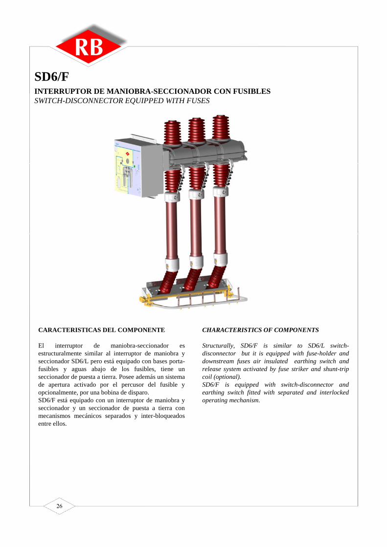
CARACTERISTICAS DEL COMPONENTE
El interruptor de maniobra-seccionador esestructuralmente similar al interruptor de maniobra yseccionador SD6/L pero está equipado con bases porta-fusibles y aguas abajo de los fusibles, tiene unseccionador de puesta a tierra. Posee además un sistemade apertura activado por el percusor del fusible yopcionalmente, por una bobina de disparo.SD6/F está equipado con un interruptor de maniobra yseccionador y un seccionador de puesta a tierra conmecanismos mecánicos separados y inter-bloqueadosentre ellos.
Structurally, SD6/F is similar to SD6/L switch-disconnector but it is equipped with fuse-holder anddownstream fuses air insulated earthing switch andrelease system activated by fuse striker and shunt-tripcoil (optional).SD6/F is equipped with switch-disconnector andearthing switch fitted with separated and interlockedoperating mechanism.
CHARACTERISTICS OF COMPONENTS
INTERRUPTOR DE MANIOBRA-SECCIONADOR CON FUSIBLESSWITCH-DISCONNECTOR EQUIPPED WITH FUSES
SD6/F
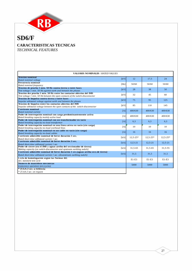
SD6/FCARACTERISTICAS TECNICASTECHNICAL FEATURES
Tensión nominalRated nominal voltageFrecuencia nominalRated nominal frequancyTensión de prueba 1 min. 50 Hz contra tierra y entre fasesTest voltage 1 min. 50 Hz against earth and between the phasesTensión dce prueba 1 min. 50 Hz entre los contactor abiertos del IMSTest voltage 1 min. 50 Hz between the open contacts of the switch-disconnectorTensión de Impulso contra tierra y entre fasesImpulse withstand voltage against earth and between the phasesTensión de Impulso enter los contactos abiertos del IMSImpulse withstand voltage between the open contacts of the switch-disconnectorCorriente nominalRated nominal currentPoder de interrupción nominal con carga predominantememte activaRated breaking capacity mainly active loadPoder de interrupción nominal con un transformador en vacíoRated breaking capacity no-load transformerPoder de interrupción nominal en una línea aérea en vacío (sin carga)Rated breaking capacity no-load overhead linesPoder de interrupción nominal en un cable en vacío (sin carga)Rated breaking capacity no-load cablesCorriente admisible nominal de breve duración 1 sec.Rated short-time withstand current 1 sec.Corriente admisible nominal de breve duración 3 sec.Rated short-time withstand current 1 sec.Poder de cierre (en el IMS y aguas arriba del seccionador de tierra)Making capacity (on switch-disconnector and upstream earthing switch)Corriente admisible nominal de breve duración 1 sec.(aguas arriba secc.de tierra)Rated short-time withstand current 1 sec. (downstream earthing switch)Ciclo de homologación según las Normas IECIEC standard test cycleNúmero de maniobras mecánicasEndurance operation test (cycles)
31,5-65 31,5-65 31,5-55
5000 5000 5000
E1-E3 E1-E3E1-E3
31,5
12,5-21
10 10
16 16
12,5-21
12,5-25* 12,5-25*
400/630
400/630 400/630
6,3
12
28
32
24
38 50
45 60
50/60 50/60
VALORES NOMINALES / RATED VALUES
16
12,5-25*
400/630
400/630
6,3
17,5
95
50/60
85
31,5
10
12,5-21
75
31,5
125
6,3
110 145
400/630
[kV]
[Hz]
[kV]
[kV]
[kV]
[kV]
[A]
[A]
[A]
[A]
[A]
[kA]
* 25 kA-2 sec. a richiesta* 25 kA-2 sec. on request
[kA]
[kA]
[kA]

SD6/FDIMENSIONES GENERALES E INSTALACIONOVERALL AND INSTALLATION DIMENSIONS
1) Inter-bloqueo apertura puerta / Mechanical interlock between the earthing-switch and the door
2) Vástago impedimento apertura puerta / Stroke of the mechanical interlock between the earthing-switch and the door
3) Alojamiento inter-bloqueo de maniobra del ST / Earthing-switch operating seat interlock
4) Vástago inter-bloqueo de maniobra del ST / Stroke of the earthing-switch operating seat interlock
5) Línea frontal del tablero / Switchboard front line
6) Dimensiones de fijación del IMS en el tablero / Switch-disconnector fixing dimension
7) Varilla seccionador de puesta a tierra / Tie rod
8) Varilla/ Sprag
* Dimensiones referidas a la ventana de inspección / Dimensions are referred to the inspection window

SD6/FESQUEMA ELECTRICO 24Vcc - 48 VccWIRING DIAGRAM 24Vdc – 48 Vdc

SD6/FESQUEMA ELECTRICO 110VccWIRING DIAGRAM 110Vdc

CARACTERISTICAS DEL COMPONENTE
El seccionador tipo D6 es estructuralmente similar alinterruptor de maniobra-seccionador SD6/L con loscambios descritos mas abajo.Eliminación de los contactos anti-arco.Eliminación del dispositivo soplador.El seccionador está equipado para las operaciones decierre y apertura con un mecanismo de operaciónmanual.La maniobra puede ser dotada con un enclavamientocon llave y con contactos auxiliares.El seccionador puede ser acoplado con un seccionadorde puesta a tierra tipo ST externo (en caso de ser usadocon un disyuntor).
Structurally, the disconnector type D6 is similar to theSD6/L switch-disconnector with the changes as belowlisted.Elimination of the arc-breaking contacts.Elimination of the blowing device.The disconnector is equipped, both for closing andopening operations, with a manual operatingmechanism. Operation can be fitted with a keylock,padlock facility and auxiliary contacts. Thedisconnector can be coupled with an earthing switchtype “ST” (when it is used with a circuit breaker).
CHARACTERISTICS OF COMPONENTS
SECCIONADORDISCONNECTOR
D6

Tensión nominalRated nominal voltageFrecuencia nominalRated nominal frequancyTensión de prueba 1 min. 50 Hz contra tierra y entre fasesTest voltage 1 min. 50 Hz against earth and between the phasesTensión de prueba 1 min. 50 Hz entre los contactos abiertos del IMSTest voltage 1 min. 50 Hz between the open contacts of the switch-disconnectorTensión de Impulso contra tierra y entre fasesImpulse withstand voltage against earth and between the phasesTensión de Impulso entre los cantactos abiertos del IMSImpulse withstand voltage between the open contacts of the switch-disconnectorCorriente nominalRated nominal currentCorriente nominal de la barraBus-bar rated currentCorriente admisible nominal de breve duración (1 sec.)Rated short-time withstand current (1 sec.)Corriente admisible nominal de breve duración (3 sec.)Rated short-time withstand current (3 sec.)Valor de cresta de la corriente admisible nominalRated peak withstand currentNúmero de maniobras mecánicasEndurance operation test (cycles)
* 25 kA-2 sec. a pedido* 25 kA-2 sec. on request
[kA]
[kA]
[kA]
[kV]
[kV]
[A]
[A]
[kV]
[Hz]
[kV]
[kV]
VALORES NOMINALES / RATED VALUES
12,5-25*
31,5-65
12,5-21
400/630/800
400/630/800
17,5
95
50/60
85
12
28
32
75
24
38 50
45 60
50/60 50/60
12,5-25* 12,5-25*
125
400/630/800 400/630/800
110 145
400/630/800 400/630/800
31,5-65 31,5-65
12,5-21
5000 5000 5000
12,5-21
D6CARACTERISTICAS TECNICASTECHNICAL FEATURES

D6DIMENSIONES GENERALES E INSTALACIONOVERALL AND INSTALLATION DIMENSIONS
1) Inter-bloqueo apertura puerta / Mechanical interlock between the earthing-switch and the door2) Vástago impedimento apertura puerta / Stroke of the mechanical interlock between the earthing-switch and the door3) Alojamiento del inter-bloqueo de maniobra del ST / Earthing-switch operating seat interlock4) Vástago inter-bloqueo de maniobra del ST / Stroke of the earthing-switch operating seat interlock5) Línea frontal del tablero / Switchboard front line6) Línea de fijación del IMS en el tablero / Switch-disconnector fixing dimension
* Dimensiones referidas a la ventana de inspección / Dimensions are referred to the inspection window

CARACTERISTICAS DEL COMPONENTE
La maniobra del seccionador de puesta a tierra tienelugar con un comando manual independiente, tanto parael cierre como para la apertura.El seccionador puede ser acoplado con otroscomponentes, como ser el interruptor de maniobra-seccionador y el seccionador.El seccionador de puesta a tierra está dotado de inter-bloqueos, en particular: mecanismos mutuos de inter-bloqueo entre la puerta y el seccionador de puesta atierra que permite que la puerta del compartimento solosea abierta cuando el seccionador está cerrado. Cuandola puerta está abierta, no se puede abrir el seccionadorde puesta a tierra.El bloqueo puede ser desactivado mediante unaherramienta especial, que garantiza el grado deprotección IP2X. Cuando la herramienta es removida,el bloqueo retorna a su posición original.Cuando el bloqueo es desactivado, la puerta solo puedeser cerrada si el seccionador está cerrado.La maniobra puede ser dotada de bloqueo con llave ycontactos auxiliares.El seccionador de puesta a tierra está diseñado para unacorriente de breve duración de 12,5/16/20 kA/1”.Existe también una versión con un poder de cierre de50 kA, valor de cresta.
Operation of the earthing switch takes place with ahand operating mechanism, both for closing andopening. The earthing switch can be coupled with othercomponents, such as switch-disconnectors anddisconnectors.The earthing switch is fitted with interlocks. Inparticular: mutual mechanical interlock between thedoor and the earthing switch which allows the door ofthe compartment to be opened only if the earthingswitch is closed. When the door is open it is not allowedto open the earthing switch.The lock can be deactivated by means of a special tool,which guarantees the IP2X protection degree.When the tool is removed , the lock returns on itsstarting position.When the lock is deactivated, the door can be closed
only if the earthing switch is closed.Operation can be fitted with a key lock, padlock facilityand auxiliary contacts. The earthing switches areplanned for a short-time current of 1 sec. equal to12,5/16/20 kA.Their is also a ST versione with making capacity 50 kA.
CHARACTERISTICS OF COMPONENTS
SECCIONADOR DE PUESTA A TIERRAEARTHING SWITCH
ST

Tensión nominalRated voltage
Valor de cresta de la corriente admisible nominalRated peak withstand current
Corriente admisible de breve duración (1 sec.)Rated short-time withstand current (1 sec.)
12,5-16-20
31,5-40-50
VALORES NOMINALES / RATED VALUES
12-17,5-24[kV]
[kA]
[kA]
STCARACTERISTICAS TECNICASTECHNICAL FEATURES

COMANDO IMS TIPO R
Las velocidades de las operaciones deapertura y cierre son independientes deloperador.Durante las operaciones de apertura ycierre, un resorte es cargado permitiendouna rápida operación.A pedido, existe la posibilidad de uncomando motorizado, contactos auxiliares ybloqueos con llave.
COMANDO SECCIONADOR DEPUESTA A TIERRA TIPO E
La maniobra de cierre es rápida y suvelocidad es independiente del operadormediante la energía acumulada en elresorte. La maniobra de apertura es lenta.A pedido, existe la posibilidad de contactosauxiliares y bloqueo con llave.
COMANDO IMS – PROTECCIONTRANSFORMADOR CON FUSIBLETIPO F
La velocidad de la operación de apertura ycierre, manual o motorizada, esindependiente del operador. Durante laoperación de cierre, los resortes de aperturay cierre son cargados simultáneamente. Altérmino de la operación de cierre, el resortede apertura permanece cargado permitiendouna operación rápida de apertura por mediode una bobina de disparo o del percusor delfusible.A pedido, existe la posibilidad de contactosauxiliares y bloqueos con llave.
Switch-disconnector operating mechanismtype R
The speed of the closing and openingoperations is independant by the operator.During closing and opening operations aspring is charged and quick operations areallowed.Motor operating mechanism, auxiliarycontacts and key interlocks are available onrequest.
Earthing switch operating mechanism typeE
The speed of the closing operation isindependant by the operator.During closing operation a spring is chargedand quick operation is allowed. The speed ofopening operation is dependant by theoperator.Auxiliary contacts and key interlocks areavailable on request.
Switch-disconnector operating mechanismTransformer protection with fuses type F
The speed of the closing and openingoperations is independant by the operator.During closing operation opening andclosing springs are charged at the same time.When closed position is realized openingspring remains loaded and allows quickopening by means opening coil or fusestriker.Motor operating mechanism, auxiliarycontacts and key interlocks are available onrequest.
TIPOLOGIA DE LOS COMANDOS DE OPERACIONOPERATING MECHANISM TYPES

COMANDO IMS TIPO VR
La maniobra de cierre y apertura son lentasy dependen del operador.A pedido, existe la posibilidad de contactosauxiliares y bloqueo con llave.
COMANDO SECCIONADOR DEPUESTA A TIERRA VE
La maniobra de cierre y apertura son lentasy dependen del operador.A pedido, existe la posibilidad de contactosauxiliares y bloqueo con llave.
Switch-disconnector operating mechanismtype VR
The speed of opening and closing operationis dependant by the operator.Auxiliary contacts and key interlocks areavailable on request.
Earthing switch operating mechanism typeVE
The speed of opening and closing operationis dependant by the operator.Auxiliary contacts and key interlocks areavailable on request.

SD6-L SD6/F D6 SD6/L SD6/F D6
1Grupo de comando tipo "R"
Operation mechanism type "R" •2
Gruppo di comando tipo "F"
Operation mechanism type "F" • •3
Grupo de comando tipo "E"
Operation mechanism type "E" • •4
Grupo de comando tipo "VR"Operation mechanism type "VR" •
5Grupo de comando tipo "VE"Operation mechanism type "VE" •
6Seccionador de puesta a tierra con poder de cierre
Internal Earthing Switch with making capacity • •7
Seccionador de puesta a tierra interno sin poder de cierre
Internal Earthing Switch without making capacity • •8
Kit motorización 24/48/110Vcc - 110/220Vca (superando el punto muerto)
Motorization system 24/48/110Vdc - 110/220Vac (dead point exceeding) •9
Kit motorización 24/48/110Vcc - 110/220Vca (con apertura rápida)
Motorization system 24/48/110Vdc - 110/220Vac (quick opening operation) • •10
Bobina de apertura 24/48/110Vcc - 110/220Vca
Opening coil 24/48/110Vdc - 110/220Vac • (*) •11
Bloqueo con llave con Aparato Principal abierto
Key lock Main Equipment open position • • •12
Bloqueo con llave con Aparato Principal cerrado
Key lock Main Equipment close position • • •13
Bloqueo con llave con Secc. de Tierra abierto
Key lock Earthing Switch opened position • • •14
Bloqueo con llave con Secc. de Tierra cerrado
Key lock Earthing Switch closed position • • •15
Tres aisladores capacitivos y luz de presencia de tensión
Three capacitor insulators and lamps for voltage presence • • •16
Componentes para el bloqueo de la puerta
Door interlock components • • •17
Manilla de comando
Operation handle • (**) • (**) • (**)
18Contactos auxiliares 2NA+2NC Aparato Principal Auxiliary
contacts 2NO+2NC Main Equipment • • •19
Contactos auxiliares 2NA+2NC Secc. de Tierra
Auxiliary contacts 2NO+2NC Earthing Switch • • •20
Seccionador de tierra 3,15 kA sin poder de cierre
Down Earthing Switch 3,15 kA without making capacity • •21
Seccionador de tierra 16 kA sin poder de cierre
Down Earthing Switch 16 kA without making capacity •22
Seccionador de tierra 12,5 kA con poder de cierre de 31,5 kA
Down Earthing Switch 12,5 kA with making capacity 31,5 kA •23
Seccionador de tierra 21 kA sin poder de cierreDown Earthing Switch 21 kA without making capacity •
24Ventana inspeccion contactos de tierra en el Aparato Principal
Window on the Main Equipment for earthing contacts • • •25
Manómetro presión gas SF6
SF6 Pressure Gauge • • •26
Pulsador apertura rápida Aparato Principal
Push button for quick opening of Main Equipment •(*) •27
Panel frontal ejecución en 375 mm
Front cover for 375 mm version • • •28
Panel frontal en ejecuión de 500 mm
Front cover for 500 mm version • • •
Equipaggiamento
standard
Standard Version
Equipaggiamento
opzionale
Optional Version
ACCESORIOS
ACCESSORIES
Pos.
Item
(**) N. 1 every 3 supplied equipments (n. 1 minimum)
(**) Una (1) unidad por cada tres aparatos suministrados (mínimo 1)
(*) Available only with option n. 2
(*) Disponible solo con opción 2

FundacionesEl tablero está normalmente predispuesto para laconexión por abajo de ambos circuitos, el de mediatensión y el de los circuitos auxilaires.Antes de la instalación es necesario disponer detrincheras bajos las celdas. El diseño de la fundación seindica en la figura superior.Fijación al pavimento (radier)El tablero puede ser fijado directamente al radier opuede ser montado sobre bases metálicas. Para la fijación directa sobre el radier, use pernos deexpansión en correspondencia con las perforaciones dela base. Para la fijación a una base metálica se requierenbloques especiales con penos. La base de fierro debeestar fija y embebida en el concreto.En cualquier caso, la superficie de fijación debe estarhorizontal y bien nivelada.Distancia hacia los murosEl tablero debe ser montado respetando las siguientesdistancias contra los muros :100 mm. En la parte posterior200 mm. Hacia las paredes laterales
FoundationsThe switchboard is normally for connection of the boththe medium voltage circuit and the auxiliary circuitsfrom below.Before switchboard installation, it is necessary to drillspecial passage holes underneath each cubicle. Thegeneral foundation drawing is shown in the figure asabove.Fixing to floorThe switchboard can be fixed directly to the floor orcan be placed on special iron bases. For direct fixing to floor, use expansion anchoring
bolts in correspondence with the fixing holes of thebase
Special blocks with bolts are required for fixing withbase irons. The iron bases must be fixed andembedded in the concrete surface.
In any case the fixing surface must be horizontal andcompletely level.Distances from the wallsThe switchboard will be placed near the wall respectingthe following distances:100 mm. from the back wall200 mm. from the lateral walls
FONDAZIONI E FISSAGGIO A PAVIMENTOFIXING TO FLOOR AND FOUNDATION
A 375 500 750 1125B 275 400 650 1025

ME6 - Ed. 01/07
Gastón Tapia RojasIngeniero División Equipamiento
Fono: (56-02) 6204219Fax: (56-02) 6204257Cel: (56-07) [email protected] nuestra página www.eecol.clSkype ID: gastontapia