Embed Size (px)
Citation preview

†Department of Computer Science – University of Rome “Sapienza” – Italy
Cellular systems & GSM
Wireless Systems, a.a. 2014/2015 Un. of Rome “La Sapienza”
Chiara Petrioli†

2
Reference book
per questo argomento usare come riferimento il testo - O. Bertazioli, L. Favalli, GSM-GPRS, Hoepli Informatica
2002.
Si ringraziano per il materiale fornito, da cui sono state tratte molte di queste slide il Prof. Antonio Capone, Politecnico di Milano (corso di retiradiomobili)
e il Prof. Giuseppe Bianchi, Universita’ di Tor Vergata)
†Department of Computer Science – University of Rome “Sapienza” – Italy
GSM cellular systems architecture
Wireless Systems, a.a. 2014/2015 Un. of Rome “La Sapienza”
Chiara Petrioli†

4
General features
• 2a Generation (2G) cellular system • Carrier bandwidth=200KHz • Multicarrier TDMA multiple access (8 slots per carrier, thus 8 channels per
carrier)à TDMA/FDMA • Full Duplex: Frequency Division Duplex (FDD) • Modulation: GMSK; Spectrum efficiency: 1,35bps/Hz; Gross bit rate per carrier:
270,822 kbit/s • 13Kbps full rate coder, 6.5Kbps half rate coder • 992 full rate channels at 900Mhz, 2992 full rate channels for DCS 1800Mhz • Frequency reuse • Power control, discontineous transmission • Adaptive equalization • Services
– telephony with many additional services – circuit swirching data network (single-channel or multi-channel) – packet switching data network (GPRS - General Packet Radio Service)

5
Allocated frequencies
• In UK and USA it uses bands around 1900 MHz instead of around 1800 MHz (1850÷1910 uplink, 1930÷1990 downlink).
890
esteso downlink esteso uplink
DCS/1800
F[ MHz ] 915 935 960
925 1710 1785 1880 1805 1805
124+49 carriers 124+49 carriers 374 carriers 374 carriersi
uplink downlink
GSM /900
uplink downlink
880
distance between the frequencies used
for tx and rx set to 45 Mhz
distance between the frequencies used
for tx and rx set to 95 Mhz

6
Allocated frequencies
• In UK and USA it uses bands around 1900 MHz instead of around 1800 MHz (1850÷1910 uplink, 1930÷1990 downlink).
890
esteso downlink esteso uplink
DCS/1800
F[ MHz ] 915 935 960
925 1710 1785 1880 1805 1805
124+49 carriers 124+49 carriers 374 carriers 374 carriersi
uplink downlink
GSM /900
uplink downlink
880
distance between the frequencies used
for tx and rx set to 45 Mhz
distance between the frequencies used
for tx and rx set to 95 Mhz
It requires less power to tx to a given distance d at lower
frequencies.
The lower portion of the spectrum is allocated to uplink channels, saving MS consumed
power

7
Carriers and channels
• Center frequencies are spaced 200 kHz
• Gross bit rate per channel: 270.833 Kb/s • Carriers are identified by a ARFCN (Absolute Radio Frequency
Channel Number) • GMSK (Gaussian Minimum Shift Keying) modulation • The two carriers used for transmission/reception to/from a device
are always 45 MHz apart in GSM 900- They are spaced of a different fixed bandwidth (95 MHz) in DCS 1800
f 200 kHz

8
TDMA Frame
• On each radio carrier the TDMA structure allows us to create up to 8 channels for the transmission of voice encoded at 13 Kb / s
3 1 0 7 6 5 4 3 1 0 7 6 5 2 2
0 7 6 5 4 3 1 0 7 6 5 4 3 2 2
TDM Frame - 4.615 ms
BTS Transmits f down
MS Transmits f up
Time slot = 577 µs (156.25 bits)

9
Other key features
• Power Control – the power emitted from the stations, mobile and base, is adjusted
according to the conditions of propagation
• Discontinous Trasmission – during pauses in speech, coded voice transmission is interrupted to
reduce interference and energy consumption

3.2 – GSM Architecture
Si veda: - O. Bertazioli, L. Favalli, GSM-GPRS, Hoepli Informatica 2002.

High level network architecture (1/2)
SIM
ME: Mobile equipment
Services / Applications
Core Network
(CN) Ext.
network
UE: User equipment
Access Network
(AN)

High level network architecture (2/2)
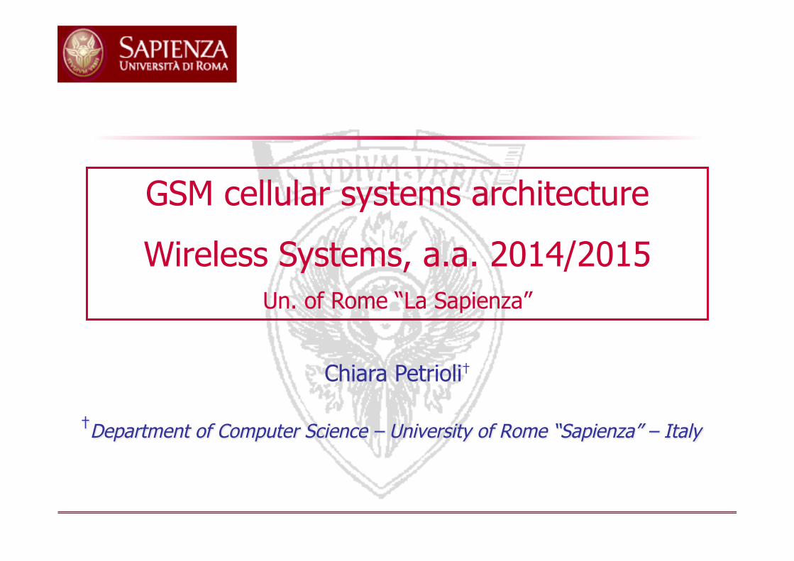
• The network contains functionally of: User Equipment (UE), Access Network (AN), and Core Network (CN) – User equipment: Interfaces the user, handles radio functionality – Access network: Communication to and from the user equipment,
handles all radio related functionality in the network – Core network: Communication between access network and external
networks, handles all switching and routing • Services and applications lie above the network
13
Network architecture
BTS
BSC
Rete telefonica
fissa
ISDN/PSTN
OMC
EIR
BSC
BSC
Um
Um
Um
Um
Abis
Abis Abis
Abis
BSC
A
A
A
A
E
AuC
MSC
GMSC
VLR
VLR HLR
BSS
NSS
OMSS
RS Radio Subsystem:
MS+BS Subsystem
Base Station
Subsystem
BTS
BTS
BTS
Operation and Maintenence Subsystem
Radio resource
management BTS=Base transceiver Station
BSC= Base Station Controller

14
Architettura della rete
BTS
BSC
Rete telefonica
fissa
ISDN/PSTN
OMC
EIR
BSC
BSC
Um
Um
Um
Um
Abis
Abis Abis
Abis
BSC
A
A
A
A
E
AuC
MSC
GMSC
VLR
VLR HLR
BSS
NSS
OMSS
RS Network Switching Subsystem
Radio Subsystem:
MS+BS Subsystem
Base Station
Subsystem
BTS
BTS
BTS
Operation and Maintenence Subsystem
Authentication
center
Equipment identity
register
Mobility management
Call Management

15
GSM Areas
• PLMN (Public Land Mobile Network) Area: – Service area of a cellular network
• MSC/VLR Area: – Area managed by an MSC. Data regarding users in the area are temporarly
stored in a database called VLR associated to the MSC • Location Area:
– a MSC/VLR area is logically divided into one or more Location Area (LA). If a user changes LA he(she has to perform a location update. LA are identified by the LAI (Location Area Identifier), which is transmitted by the BTS of the LA over the broadcast control channel.
• Cell: – Area covered by a BTS. It is identified by a BSIC (Base Station Identity
Code), which is transmitted by the BTS over the broadcast control channel.

16
(Mobile Station - MS)
• It is the terminal owned by the user • Three categories depending on the nominal power:
– Vehicular: antenna can emit up to 20 W – laptops: the antenna can emit up to 8 W to the antenna, are
transportable, but they need a considerable source of power to operate (eg. laptops, fax, etc.)
– personal (hand-terminal): the antenna can transmit up to 2, it is the "mobile phone"

17
(Mobile Station - MS)
GSM 900 MHz DCS 1800 MHz GSM 900 MHz DCS 1800 MHz1 . 1 . 1202 8 0,25 960 303 5 4 600 4804 2 . 240 .5 0,8 . 96 .
Classe Potenza massima nominale [W] Potenza media nominale [mW]
• Features – MS multi-band: can operate on different frequency bands (900,
1800, 1900, …) – MS multi-slot: can operate over different channels, in different slots
(only for GPRS) • MS is composed of an ME (Mobile Equipment) and a SIM (Subscriber
Identity Module) – ME is the terminal through which we access the cellular network
(HW, radio interface HW/SW, interface to the final user). It is identified by the IMEI (International Mobile Equipment Identifier)
– SIM activates the terminal for a given user and stores all the needed information: it identifies the user, enables terminal personalization
18
(Subscriber Identity Module - SIM
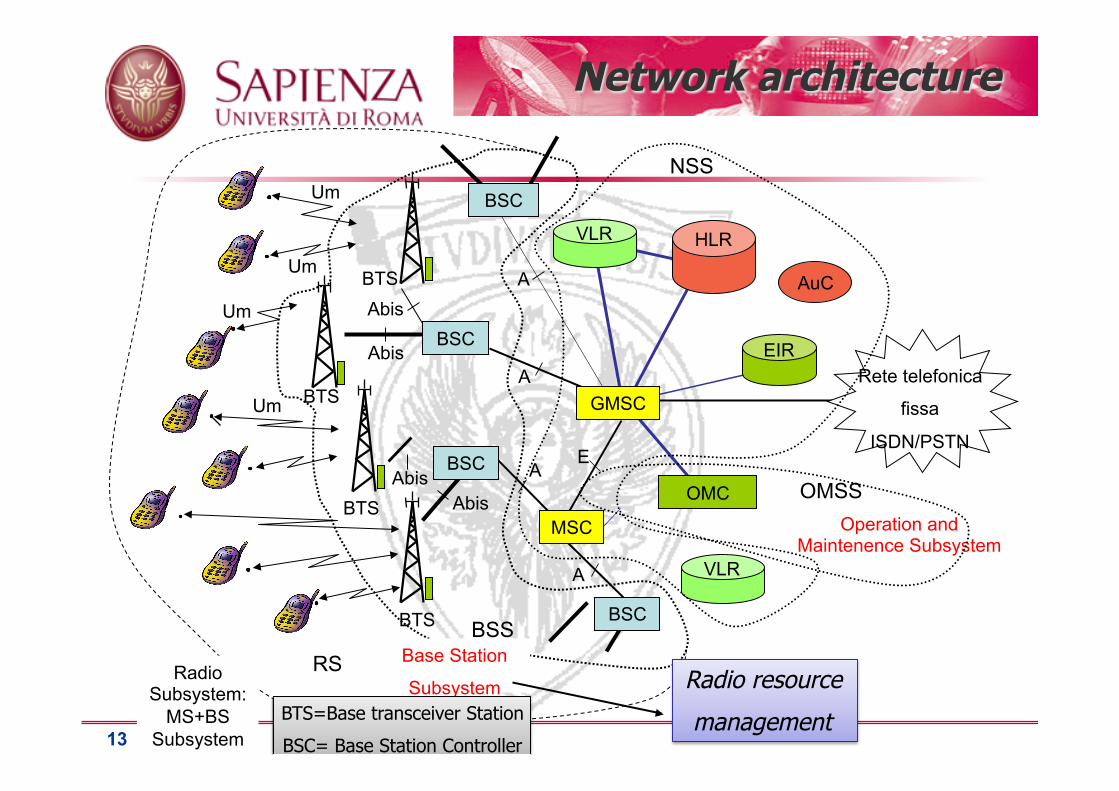
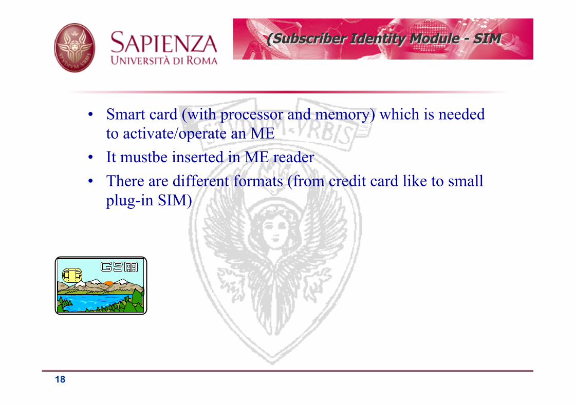
• Smart card (with processor and memory) which is needed to activate/operate an ME
• It mustbe inserted in ME reader • There are different formats (from credit card like to small
plug-in SIM)

19
Base Station System (BSS)
• BSS includes the functional units that deal with aspects of the radio system related to coverage and radio communication via a radio interface with the MS. The BSS also performs radio resource management
• BSS includes: – Base Transceiver Station (BTS) – HW / SW components that enable the transmission and reception of information through
the radio interface. It has purely executive tasks (e.g. encryption, modulation, coding): resource management is handled by the BSC
• Base Station Controller (BSC) – monitors and manages the resources of a group of BTS. From the BTS it receives the
information about the state of the radio interface. It uses information on the quality of the links to make decisions on handover. The BSC sends the commands to the BTS for configuration and management. It also allocates radio resources and channels connecting BSC/BTS in order to initiate a call or perform handover. Examples of functionality carried out by the BSC: reservation / release of radio channels, handover (intraBSC), transcoding etc ....

20
Base Transceiver Station (BTS)
• The BTS is the element that has the task of implementing the low-level protocols of the radio interface
• And then to transmit and receive signals from MS implementing the functionality of modulation, coding and multiplexing of physical channels. It performs frequency hopping (if enabled) and encryption.
• Its task is also to perform quality measurements on the physical channels and to receive those made by MS (all measurements are then reported to the BSC that makes the decisions on when/whether to handoff)
• The BTS brodcasts on a control channel the System Information message, which contains data and parameters that are needed for the MS to access the network (Cell identity, Location Area identity, the minimum received signal level required to access the network, etc.);
• The BTS is also in charge of sending paging messages to locate the current position of a user.
• It interfaces to the BSC (only services in the circuit) by means of PCM channels at 64 kbit / s
• Connect the PCM channels with those of the radio interface (traffic and signaling)

21
Struttura BTS
• The BTS (Base Transceiver Station) is usually functionally divided into – TRX (Transceiver)
ü radio elements responsible for reception and transmission of a single radio carrier:
– Transmitter: modulation, power amplifier,… – Receiver: diversity, demodulation,… – Signal processing – TRX controller
• BCF (Common Base Function) – control element of TRX that performs the common functions
ü syncrhonization, frequency hooping computation – and interface with the BSC

22
BTS functional scheme
…. ….
Combiner
BSC
A-bis Interface
PCM line or Radio system 2 Mb/s
TX RX
Signal Processing
TRX Controller
TRX
one TX antenna Splitter
TX RX
Signal Processing
TRX Controller
TRX
two RX antennas
…………….... BCF
Base
Common
Functions

23
Transcoder Rate Adaptation Unit (TRAU)
• GSM voice coding is 13 kbps while the PCM provides 64 kbps • The transcoding is performed by the TRAU • The TRAU may be in the BTS, but more often it is in the BSC • In this case, the 13 kbps flows must be transported without
coding in the channels at 64 kbps • On each PCM channel 4 13Kbps flows are multiplexed (after
transformation into streams at 16Kbps with the addition of redundancy)
• For each GSM carrier (8 channels at 13 kbps)we need 3 PCM channels at 64 kbps – one for the signal carried by control protocol LAPD – 2 to carry the information of the multiplexed 8 telephone channels

24
Transcoder Rate Adaptation Unit (TRAU)
0 1 2 15 16 17 30 31 0 1 30 31 … …
125 µs
Start of the frame
signaling channel
1 2 15 16 29 30
MSC BSC BTS
PCM channels
(64 kbit/s) TRAU
PCM channels
(64 kbit/s)
1 channel per voice
circuit
4 voice circuits multiplexed into a PCM channel
GSM channels
(13 kbit/s)

25
Base Station Controller (BSC)
• A BSC controls a large number of BTS: from several tens to
several hundreds • The main tasks of the BSC are:
– the configuration of each cell by assigning traffic and control channels
– The set up and release of connections between channels related to the A and Abis interface
– the management of handovers between controlled BTS – the management of the paging messages: paging messages are
distributed to the BTS in the LA where the user is located – the analysis of the link quality and power level measurements
performed by the BTS and MS, and the decision of the necessity of handover

26
Base Station Controller (BSC)
• The BSC is basically concerned with the management of radio resources (Radio Resource Management)
• From the functional point of view it is a switching node, – but it does not perform the task of routing calls (that task is performed
by the MSC) – instead it connects the circuits of the BTS with those of the MSC,
possibly carrying out the trans-coding (TRAU) – It switches the circuits in case of handover (intra-BSC)
• The BSC can be placed at the site of an MSC or be standalone, or it can be positioned near (or together) to some BTS

27
Operation and Maintenence Subsystem (OMSS)
• Include the functional units responsible for monitoring the network, its maintenance and remote management
• It deals with: – configuring the functionality of all network
devices – displayed alarms on malfunctioning elements – shows the statistics on data traffic
• etc..

28
Operation & Maintenance Sub-system (OSS)
• Network measurement and control functions • Monitored and initiated from the OMC
(Operation and Maintenance Center) • Basic functions
– Network Administration ü configuration, operation, performance management, statistics
collection and analysis, network maintenance
– Commercial operation & charging ü Accounting & billing
– Security Management ü E.g. Equipment Identity Register (EIR) management
O&M functions based on ITU-T TMN standards (Telecommunication Network Management) – complex topic out of the scopes of this course

29
OMSS
Operation and Maintenance Subsystem (OMSS)
• Includes the functional entities in charge of network management, operation and maintenance
• Hierarchical structure – Regional OMC (Operation & Maintenence Centre) – NMC (Network Management Centre)
NMC
HLR OMC OMC
EIR MSC
BSC BSC
HLR
EIR MSC
BSC BSC
GSM Management Center
GSM Support Center
(Account and Billing) PCS
Personalization Center
for SIM
(caricamento
Lato utente e AuC
Dati utente, IMSI, Ki)

30
Network Switching Subsystem (NSS)
– Mobile Switching Center (MSC): ü Telephone switching center for mobile users
– Visitor Location Register (VLR): ü It is a database (usually implemented in the central MSC) that contains
information about users in the area managed by the MSC – Home Location Register (HLR):
ü It is the main database that is responsible for storing the information of mobile users. It contains, among others, the information necessary to identify the VLR which is in charge of each subscribed user.
– Authentication Center (AuC): ü normally associated with the HLR which contains the keys and the
procedures for authenticating a mobile user. The AuC computes the keys for authentication and encryption.
– Equipmente Identity Register (EIR): ü contains the IMEI of all devices authorized to access the service
■ It is the subsystem that is responsible for circuit switching to the mobile users, managing alsouse mobility. It includes:

31
Mobile Switching Centre (MSC)
• The MSC is a switching element which additionally performs
mobility management • It is normally associated with a VLR that stores data of those
users currently located under its area • The MSC is connected to the BSC of its (MSC/VLR) area as
well as to other MSC – Connection is through PCM channels – part of the resources allocated for the interconnection support control
information exchange, performed through SS7 common channel signaling.
– One or more MSC (Gateway MSC) for each PLMN network us interfaced to the fixed telephone network for routing to and from fixed users.

32
Mobile Switching Centre (MSC)
• An MS can be reached by fixed users using the phone number
(MSISDN) • The call is routed to the GMSC, which identifies the HLR that
contains user information associated with the MSISDN and queries it to determine how to route to the mobile user current MSC
• the HLR returns the MSRN (Mobile Station Roaming Number) – It has in its record the VLR/MSC associated to the user and queries it to get the
MSRN
• Temporary MSRN number (same struct. MSISDN) is assigned by the visited VLR
• MSRN to the GMSC allows the GMSC to route the call to the MSC area where the user is located

33
Mobile Switching Centre (MSC)
• The MSC provides the following functionalities
– CM (Connection Management) ü originating call, terminating call, gateway
– MM (Mobility Management) ü location updating, periodic registration, authentication, ecc.
• The MSC is the core entity in charge of signaling; It implements protocols to exchange information with other elements of the network – DTAP (Direct Tranfer Application Part)-protocol to exchange
information over a logical channel with the MS – BSSMAP (BSS Management Application Part) protocol to
exchange information with the BSC – MAP (Mobile Application Part) protocol to exchange
information with the other network elements (MSC, VLR, HLR, EIR, AuC)

34
HLR Home Location Register (HLR)
• It is a permanent database uniquely associated to a GMSC • It stores information about all MS whose default location is at
the considered GMSC • HLR stores permanent information such as the IMSI
(International Mobile Subscriber Identity), the phone number of the SIM card and its associated authentication key, supplementary services to which the user has subscribed, etc..
• HLR also stores temporary information such as the address of the VLR at which the user can be found, parameters for identification and encryption, any phone number listed for call forwarding, etc..

35
HLR Home Location Register (HLR)
• Main tasks: – Managing localization, store the VLR number of
each registered user – Sending routing information (MSRN) to the
GMSC – Registration, Cancellation and activation/
deactivation of additional services – storage and supply to the VLR of the parameters of
authentication and encryption – management of user data

36
VLR Visitor Location Register (VLR)
• It is a temporary database that contains important data for serving the MS currently under the jurisdiction of the MSC to which the VLR is associated.
• All the permanent data of a user currently under that MSC/VLR area are duplicated in the VLR (i.e., they are not only stored in the HLR but also in that VLR), with the difference that the IMSI is "mapped" on a TMSI (Temporary Mobile Subscriber Identity) to avoid transmitting the IMSI in clear and protect the user from "intrusion”. The TMSI is changed frequently and is also linked to the location of the mobile (cell identifier)
• VLR plays a fundamental role in the management of the calls that come from MS

37
Security procedures
• Authentication:
– has the task of verifying the user's identity and protect against fraudulent use of identification
• Encryption: – The confidentiality of the communication itself on the radio link is performed by the
application of encryption algorithms and frequency hopping, which could only be realized using digital systems and signaling.
• The subscriber's anonymity is also ensured through the use of temporary identification numbers.

38
Security procedures
– Ki ü user authentication key of 128 bits stored in the SIM and AUC
– RAND ü 128-bit random number generated by the AuC and then sent to the MSC
– A3 ü authentication algorithm stored in the SIM and AuC
– A8 ü algorithm that determines the encryption key Kc, which is stored in the
SIM and AuC
Triplets (RAND, SRES, Kc)
are generated sequentially for each IMSI and stored in
in the HLR
Output of the procedures: ■ Kc
– Encryption key
■ SRES – Output of the authentication algorithm

39
Security procedures
• Authentication: MS Network
A3
Ki
Random
Num. generator
A3
Ki RAND
RAND
SRES(network) SRES(ms)
uguali? Si No
Access
enabled
Access
denied
Challenge-response
mechanism

An additional level of security is provided by having the means to change the ciphering key,
making the system more resistant to eavesdropping. The ciphering key may be changed
at regular intervals as required by network design and security considerations. 40
Security procedures
• Encryption MS Network
A8
Ki
Random
Num. generator
A8
Ki RAND RAND
Kc Kc
A5 A5 Encrypted information
Stored in the BTS
41
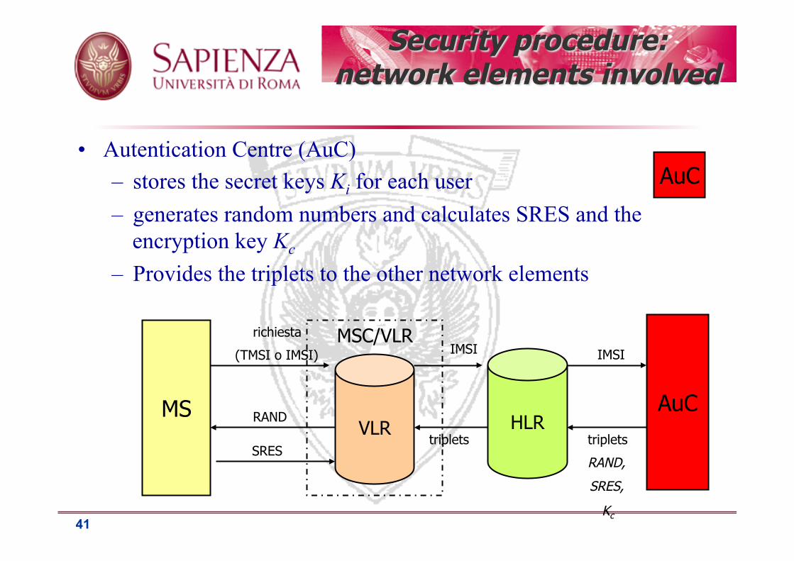
• Autentication Centre (AuC) – stores the secret keys Ki for each user – generates random numbers and calculates SRES and the
encryption key Kc
– Provides the triplets to the other network elements
MS
MSC/VLR
VLR HLR AuC
AuC
richiesta
(TMSI o IMSI) IMSI IMSI
triplets
RAND,
SRES,
Kc
triplets
RAND
SRES
Security procedure: network elements involved

42
BSS
Security procedure: network elements involved
• BSS/NSS elements involved in data encryption
MS MSC/VLR
VLR
richiesta
RAND
SRES
Kc
A5 informazioni
cifrate informazioni
in chiaro A5
A8 Kc
Ki

43
Security procedures: TMSI allocation
• Ogni comunicazione è iniziata dalla MS che invia il proprio identificativo (IMSI) per farsi riconoscere prima che venga attivata la procedura di autenticazione
• Per evitare che il IMSI venga intercettato sull’interfaccia radio e ne possa essere fatto un uso fraudolento il VLR alloca ad ogni MS un TMSI (Temporary Mobile Subscriber Identity)
• L’IMSI viene usato dalla MS solo quando non ha ancora un TMSI
• Ad ogni location update il VLR può allocare un nuovo TMSI al mobile che nelle comunicazioni successive adotterà il TMSI invece del IMSI

44
IMSI
• It is the identification number for use in the network • It consists of 3 fields:
– MCC: Mobile Country Code (3 digits) – MNC: Mobile Network Code, which identifies the operator that provides
the service (2 digits) – MSIC: Mobile Subscriber Identification Number, which identifies the SIM
(up to 10 digits)
• For example, the number 222 01 4572228769, identifies an Italian SIM (222) of the operator TIM (01)
• The telephone number of the apparatus in question (MSISDN) is completely independent from the IMSI; the digits of the prefix (for ex. 0330 or 0347) identify the HLR and then the GMSC which the device is connected

45
EIR Equipment Identity Register
(EIR)
• Database whose use is at the discretion of the operator • Contains the identification and characteristics of GSM terminal
equipment (TE), together with the manufacturer, country of manufacture, etc.
• It can be used to protect the network from the use of equipment stolen or not compliant to standard
MSC/VLR MS
EIR
Connection request
IMEI request
IMEI response Check on the IMEI
response

46
IMEI management
• Protection against stolen and malfunctioning terminals • Equipment Identity Register (EIR): 1 DataBase for each operator; keeps:
– WHITE LIST: ü valid IMEIs ü Corresponding MEs may be used in the GSM network
– BLACK LIST: ü IMEIs of all MEs that must be barred from using the GSM network ü Exception: emergency calls (to a set of emergency numbers) ü Black list periodically exchanged among different operators
– GRAY LIST: ü IMEIs that correspond to MEs that can be used, but that, for some
reason (malfunctioning, obsolete SW, evaluation terminals, etc), need to be tracked by the operator
ü A call from a “gray” IMEI is reported to the operator personnel

47
Numbers and IDs in GSM
• Mobile Station ISDN Number (MSISDN) It is the user mobile telephone number(<=15 cifre) Country Code - National Destination Code –Subscriber Number It is associated to a specific HLR
• Mobile Station Roaming Number (MSRN) It is assigned by the current VLR; it is communicated (upon
request) to the HLR which gives it to the requesting GMSC; it allows the GMSC to establish a circuit till the current Mobile User position
• Handover Number (communicated by the target MSC to the initial MSC in case of inter-MSC handover; it allows to reroute the call till the target MSC)
Uts
ed fo
r ro
utin
g

48
• International Mobile Subscriber Identity (IMSI) Permanently stored in the SIM and HLR, temporarly in the VLR;
uniquely indetifies the subscriber Mobile Country Code (3 cifre)--Mobile Network Code(2)—Mobile Subscriber Identification
Number
• Temporary Mobile Subscrier Identity (TMSI) Temporary ID assigned by a VLR to an MS; it allows to avoid
transmitting the IMSI in clear on the radio channel (or to transmit it only when switching on). It has a non standardized structure, and a size equal to 4 octects.
• International Mobile Equipment Identity (IMEI) Uniquely identifies a terminal equipment (HW). It is stored in
HW at the time the HW is produced. TAC =Type Approval Code (6 cifre); FAC (Final Assembly Code), 2 digits
(production/assembly site), SNR(Serial Number), 6 digits
ID a
ssoc
iate
d to
a m
obile
ent
ity
Numbers and IDs in GSM

49
• Location Area Identity (LAI) It uniquely identifies the location area under which the MS is
currently located. It is stored in the VLR. Structure: Mobile Country Code, Mobile Network Code (operatore), Location Area Code • Cell Global Identity (CGI), it identifies the cell (Structure: LAI
+Cell Identity that is the ID which identifies the cell within its location area)
• Regional Subscription Zone Identity (RSZI) • Used in case of subscription only to a service within a regional
area. The ID allows to specify within which regiones users can roam.
• Base Station Identity Code (BSIC) It is a “color code” which allows the MS to distinguish among signals
received by adiacent BTS. Each BTS broadcasts its BSIC on the logical Synchronization channel (SCH) on a predefined carrier.
Rela
ted
to m
obili
ty m
anag
emen
t Numbers and IDs in GSM

50
Info stored in GSM network
• IMSI (àHLR,VLR) • MSISDN (àHLR, VLR) • TMSI (àVLR) • MS category (àHLR,VLR) • RAND,SRES,Kc (àHLR, provided upon request to the VLR) • Cyphering Key Sequence Number (àVLR) • MSRN (àVLR, provided to the HLR upon request) • LAI (àVLR) • VLR number (àHLR) • HLR number (àVLR) • subscription restrictions (àHLR) • data associated to basic and supplementary services
(àHLR,VLR) • IMSI detached flag (àVLR) • Call barring (àHLR, some VLR)

3.3 – Radio Interface
Wireless systems

52
Radio Interface
si veda
O. Bertazioli, L. Favalli, GSM-GPRS, Hoepli Informatica 2002
Capitolo 6

53
Radio Interface
f 200 kHz
3 1 0 7 6 5 4 3 1 0 7 6 5 2 2
0 7 6 5 4 3 1 0 7 6 5 4 3 2 2
TDM Frame - 4.615 ms
BTS Transmits f down
MS Transmits f up
Time slot = 577 µs
890 915 935 960 925
uplink downlink
880
FDD (Frequency Division Duplexing)
45 MHz duplex spacing
3 slot offset uplink/downlink

54
Frequency Hopping
• Multipath fading depends on the carrier used for transmission • At a given time, when transmitting to a user some carriers may
suffer high attenuation while others low attenuation
• Since FEC codes are used to increase transmission robustness, it is better if the errors due to the high attenuation suffered by a carrier are spread over multiple information flows (similarly to what we have seen when we discussed interleaving techniques)
• Frequency hopping changes the carrier used for transmission on a per slot basis, according to a predefined pseudorandom sequence
f
55
Power Control
• The output power of the MS is controlled by the BTS • The BTS sends power control commands that require the MS to
raise or lower the transmit power • The step increment / decrement is 2 dB • The objective of the control is to bring the power received from the
BTS to a predetermined level (just above what needed for reception) • The power control reduces the interference in the system by
reducing the average power of the MS with little attenuation of the channel (close to BTS)
• The power control also reduces the energy consumption of the MS

56
GSM Syncrhonization
• Carrier frequency synchronization – Each MS each MS must retrieve precisely the frequency
of the radio carrier • Slot synchronization
– Each MS must have information on the current slot • Frame synchronization
– Each MS must know the current Frame Number • Base station synchronization (optional)
– The base stations have synchronous clocks – The base stations have the same Frame Number

57
Carrier frequency synchronization
• The frequency of the radio carrier is obtained by the MS listening to the broadcast common control channel transmitted by the BTS
• On this channel, at regular intervals, a special fixed sequence of bits is transmitted at high power that is used to select the carrier frequency, and then adjust the frequency of the local oscillator

58
Slot and frame synchronization
• Many channels in GSM follow a multiframe structure (for example, the broadcast channel is broadcast every x frames)
• The sequence of frequency hopping depends on the multiframe structure
• Each MS must therefore know the number of the current frame to correctly interpret the information
• The BTS transmits on the broadcast channel the information needed for the MS to be able to reconstruct tcurrent time slot and Frame Number

59
Slot synchronization
• Up/down link transmissions go through propagation delays which depend on the relative distance between the BTS and the MS
• Each slot needs to have a guard period to compensate for synchronization errors
Time reference
(beginning of slot)
2τ Propagation delay
τ = d v
d - sistance
v – light speed

60
• We could make a conservative selection, setting the guard time to
)2(max iigT τ=
Slot synchronization

61
Slot synchronization
• The GSM network is designed to have cells with Rmax = 35 Km
• In the worst situation (at the borders of the cell) there is a guard time of 2τ = 2 x 35 / 3 x 108 = 233 µs
• which corresponds to 68.25 bits at the rate of 270.8 kb / s

62
Slot synchronization: Timing Advance
• To limit guard time: • the BTS estimates the delay and sends the information to
the MS which can then compensate by anticipating the transmission
• used in GSM : transmission is anticipated as the MS moves away from the BTS (timing advance, reduces the guard time to about 9 bits, equal to 33,3 µsec)
1) Before transmission
3) Estimated delay is
Communicated to the MS
2) Propagation delay
estimation 4) Following transmissions