Embed Size (px)
Citation preview
Des Autom Embed SystDOI 10.1007/s10617-014-9131-z
Centaur: a hybrid network-on-chip architecture utilizingmicro-network fusion
Junghee Lee · Chrysostomos Nicopoulos ·Hyung Gyu Lee · Jongman Kim
Received: 30 June 2013 / Accepted: 3 February 2014© Springer Science+Business Media New York 2014
Abstract The escalating proliferation of multicore chips has accentuated the criticality ofthe on-chip network. Packet-based networks-on-chip (NoC) have emerged as the de factointerconnect of future chip multi-processors (CMP). On-chip traffic comprises a mixture ofdata and control messages from the cache coherence protocol. Given the latency-criticalityof control messages, in this paper we aim to optimize their delivery times. Instead of treatingthe on-chip router as a monolithic component, we advocate the introduction of an ultra-low-latency ring-inspired (i.e., utilizing ring primitive building blocks) support micro-networkthat is optimized for control messages. This µNoC is fused with a throughput-driven con-ventional NoC router to form a hybrid architecture, called Centaur, which maintains separatedata paths and control logic for the two fused networks. Full-system simulation results from a64-core CMP indicate that the proposed fused Centaur router improves overall system perfor-mance by up to 26 %, as compared to a state-of-the-art router implementation. Furthermore,hardware synthesis results using commercial 65 nm libraries indicate that Centaur’s area andpower overheads are 9 and 3 %, respectively, as compared to a baseline router design. Moreimportantly, the new design does not affect the router’s critical path.
Keywords Networks-on-chip · Interconnection networks · Segregated/separatednetworks
J. Lee (B) · J. KimGeorgia Institute of Technology, Atlanta, GA, USAe-mail: [email protected]
J. Kime-mail: [email protected]
C. NicopoulosUniversity of Cyprus, Nicosia, Cypruse-mail: [email protected]
H. G. LeeDaegu University, Gyeongsan, South Koreae-mail: [email protected]
123
J. Lee et al.
1 Introduction
The advent of chip multi-processors (CMP) and the quest toward many-core microproces-sors with tens, or even hundreds, of processing elements necessitates a scalable on-chipcommunication infrastructure. Packet-based networks-on-chip (NoC) have emerged as themost viable candidate for the interconnect backbone of future CMPs. In their current andforeseeable future incarnations, CMPs operate on the premise of shared-memory multiproces-sors, whereby all cores share the off-chip main memory. Consequently, traffic in the NoCincludes: (a) Data traffic (actual cache lines and memory contents), and (b) Control traffic(request messages and coherence protocol exchanges). These two fundamentally differentmessage classes invariably define the on-chip traffic characteristics of any CMP.
Despite the fact that control messages are—essentially—overhead to the useful data trans-fers, they are actually responsible for a non-negligible portion of network traffic: our simu-lations indicate that for the multithreaded benchmarks contained in the PARSEC benchmarksuite [8], control packets account for about 34 %, on average, of all in-flight traffic, and72 % of all generated packets. Note that this result assumes a directory-based cache coher-ence protocol. For broadcast-based snoopy protocols, this percentage is even higher [5]. It istrue that not all control messages are equally latency-critical [13]. However, the sheer volumeof such packets inundating the network warrants special attention.
Control messages are usually single-flit packets (a flit is the smallest unit of flow controlin the network; a packet comprises a number of such flits). Hence, the benefits of wormholerouting (the most established flow control mechanism in modern NoC implementations, dueto its low buffering demands) are not exploited by these single-flit packets. Instead, controlpackets have to pass through all the router pipeline stages, since they are treated as normalheader flits.
Our primary research driver in this work is to truly decouple the two message types (controland data) in an effort to best cater to the nuances and underlying characteristics of each one.Toward this end, we hereby propose Centaur1, a hybrid NoC router architecture that fuses twoseparate networks, each of which is specifically architected to support traffic from one of twomessage classes: control and data. Centaur’s fundamental premise is the notion of LOGICALNoC Fission realized through PHYSICAL NoC Fusion. More specifically, Centaur logicallysegregates on-chip network traffic into two independent networks: (1) a very lightweight, yetultra-low-latency micro-network (henceforth called µNoC) to handle all control messages,and (2) a generic, VC-based wormhole-switched NoC dedicated to data messages to serve asthe main network (henceforth called DNoC, an abbreviated version of “Data NoC”). We callthis network segregation/separation process NoC Fission. This concept can be extended tomultiple separate micro-networks, in order to serve more message classes (similar to Intel’sfour-ringed on-chip network in Sandy Bridge [29]).
The segregated networks are especially useful when the network needs to carry non-negligible amounts of single-flit packets (e.g., the control messages of the cache coherenceprotocol). Moreover, Centaur is especially amenable to systems where the DNoC uses amulti-stage pipelined router.
Extensive simulation results using an execution-driven, full-system simulation frameworkand several multi-threaded applications running on a 64-core CMP demonstrate Centaur’sefficacy and efficiency: overall average network latency is reduced by up to 47 %, whileoverall system performance is improved by up to 32 %, as compared to a baseline router
1 In Greek mythology, Centaur was a hybrid creature that was part human and part horse. Much like thismythical creature, our proposed router architecture fuses two distinct networks into one entity.
123
Centaur: a hybrid network-on-chip architecture
design. Compared to a state-of-the-art router implementation based on express virtual chan-nels (EVC) [22], Centaur improves average network latency by up to 30 % and overallsystem performance by up to 26 %. Moreover, hardware synthesis results using commer-cial 65 nm standard-cell libraries indicate that Centaur’s area and power overheads are 9 and3 %, respectively. More importantly, the synthesis experiments show that the new architecturedoes not affect the router’s critical path.
The rest of the paper is organized as follows: Sect. 2 serves as a preamble by profilingthe on-chip network traffic in multi-threaded workloads. Section 3 then proceeds with adiscussion of related prior work. Section 4 presents a detailed analysis of the proposedCentaur router architecture, while Sect. 5 describes and analyzes the various simulationexperiments. Finally, Sect. 6 concludes the paper.
2 Motivation
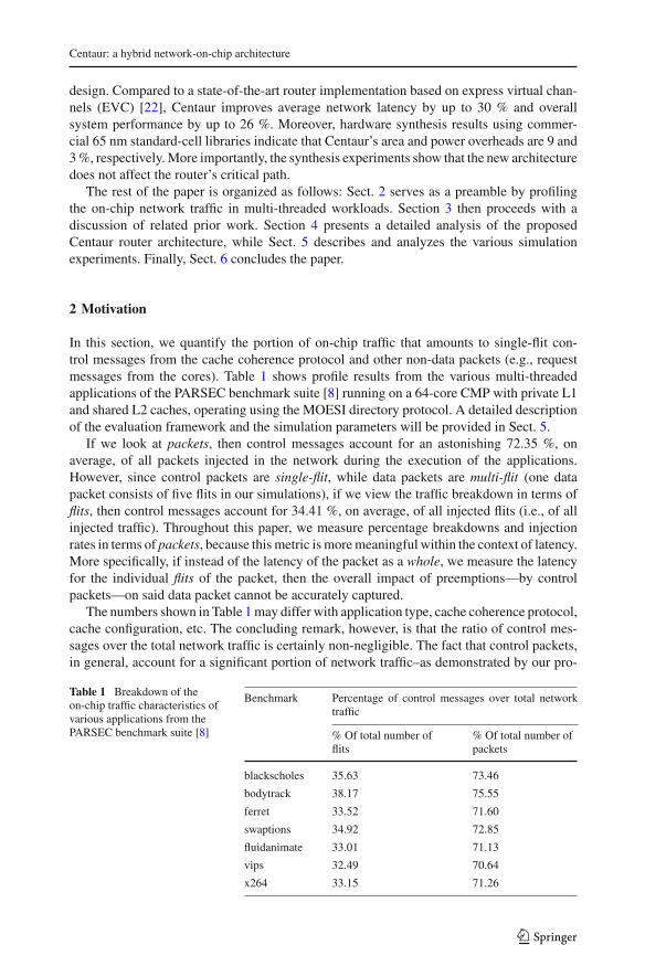
In this section, we quantify the portion of on-chip traffic that amounts to single-flit con-trol messages from the cache coherence protocol and other non-data packets (e.g., requestmessages from the cores). Table 1 shows profile results from the various multi-threadedapplications of the PARSEC benchmark suite [8] running on a 64-core CMP with private L1and shared L2 caches, operating using the MOESI directory protocol. A detailed descriptionof the evaluation framework and the simulation parameters will be provided in Sect. 5.
If we look at packets, then control messages account for an astonishing 72.35 %, onaverage, of all packets injected in the network during the execution of the applications.However, since control packets are single-flit, while data packets are multi-flit (one datapacket consists of five flits in our simulations), if we view the traffic breakdown in terms offlits, then control messages account for 34.41 %, on average, of all injected flits (i.e., of allinjected traffic). Throughout this paper, we measure percentage breakdowns and injectionrates in terms of packets, because this metric is more meaningful within the context of latency.More specifically, if instead of the latency of the packet as a whole, we measure the latencyfor the individual flits of the packet, then the overall impact of preemptions—by controlpackets—on said data packet cannot be accurately captured.
The numbers shown in Table 1 may differ with application type, cache coherence protocol,cache configuration, etc. The concluding remark, however, is that the ratio of control mes-sages over the total network traffic is certainly non-negligible. The fact that control packets,in general, account for a significant portion of network traffic–as demonstrated by our pro-
Table 1 Breakdown of theon-chip traffic characteristics ofvarious applications from thePARSEC benchmark suite [8]
Benchmark Percentage of control messages over total networktraffic
% Of total number offlits
% Of total number ofpackets
blackscholes 35.63 73.46
bodytrack 38.17 75.55
ferret 33.52 71.60
swaptions 34.92 72.85
fluidanimate 33.01 71.13
vips 32.49 70.64
x264 33.15 71.26
123
J. Lee et al.
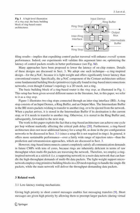
Fig. 1 A high-level illustrationof a ring stop, the basic buildingblock of ring-based routerarchitectures
filing results—implies that expediting control packet traversal will enhance overall systemperformance. Indeed, our experiments will validate this argument later on; optimizing thelatency of control packets results in better performance (see Fig. 8d).
Many approaches have been proposed to lower the latency of on-chip routers. Detailsof these designs are discussed in Sect. 3. We adopt one such technique—a ring-inspireddesign—for the µNoC, because it is light-weight and offers significantly lower latency thanconventional routers. Specifically, the µNoC component of the Centaur architecture utilizessome fundamental building blocks (primitives) typically found in ring-based interconnectionsnetworks, even though Centaur’s topology is a 2D mesh, not a ring.
The basic building block of a ring-based router is the ring stop, as illustrated in Fig. 1.This setup has been given several different names in the literature, but, in this paper, we referto it as a ring stop.
Figure 1 illustrates two ring stops connected through an inter-ring interface (IRI). A ringstop consists of an Input Demux, a Ring Buffer, and an Output Mux. The Intermediate Bufferin the IRI stores packets wishing to transfer to another ring, or to be ejected from the network.When a packet arrives, it is stored in the Intermediate Buffer if its destination is the currentstop, or if it needs to transfer to another ring. Otherwise, it is stored in the Ring Buffer and,subsequently, forwarded to the next stop.
The work in this paper exploits the fact that a ring-based architecture can achieve one cycleper hop without markedly affecting the critical path delay [20]. Furthermore, a ring-basedarchitecture does not incur additional latency for a setup flit, as done in the pre-configurationnetworks to be discussed in Sect. 3.1 (since a setup flit is not required in rings). In general, itoffers more sustainable performance—over a fairly wide range of injection rates—than theprediction and retransmission approaches, which are discussed in Sect. 3.
However, ring-based interconnects cannot completely satisfy all communication demandsin future CMPs with tens of cores, because rings are inherently deficient in terms of rawthroughput when multi-flit packets are traversing the network. Therefore, we employ a ring-inspired network as a sidekick (i.e. a supporting network) to a main data network that can han-dle the high-throughput demands of multi-flit data packets. The light-weight support micro-network employs ring primitive building blocks in a 2D mesh topology to handle the single-flitpackets, while the main network will deliver the throughput-demanding data packets.
3 Related work
3.1 Low-latency routing mechanisms
Giving high priority to short control messages enables fast messaging transfers [9]. Shortmessages are given high priority by allowing them to preempt larger packets (during virtual
123
Centaur: a hybrid network-on-chip architecture
channel allocation and switch arbitration) with lower priority. Although preempting largepackets can avoid queuing delay, the number of pipeline stages they should traverse is, infact, not changed. Hence, latency-critical short messages still experience relatively lengthyend-to-end delays.
There have been various approaches of using a pre-configuration network [17,19,23] toreduce the latency of routers. A setup flit goes through the pre-configuration network inadvance of the actual packet, in order to form a path within the main data network. Thepre-configuration network has a narrower channel and is physically separated from the datanetwork. Without a setup flit, express virtual channels (EVC) [22] achieve two cycles perhop, by virtually bypassing routers. If a setup flit is adopted, the latency is further reducedto one cycle per hop. However, the latency of single-flit packets cannot benefit from a setupflit, because the setup flit itself has to go through the regular pipeline stages [17,19,22].The setup flit may help slightly at very low injection rates, where the chance of conflict islow [23].
Prediction within the router is another approach for single-cycle routing [21,25,30]. Apacket’s next destination is predicted and forwarded within a cycle. If the prediction turnsout to be incorrect, the packet is killed and inevitably suffers a longer delay.
Employing retransmission instead of buffering, a single-cycle and buffer-less networkhas also been proposed [17]. It consists of three sub-networks: data, allocation, and nega-tive acknowledgement (NACK). The allocation network is used to pre-configure the datanetwork. When a conflict is detected, a NACK message is sent through the NACK networkfor packet retransmission. Naturally, a retransmission incurs long latencies, so the scheme ismost efficient when the probability of conflict is low.
There have also been approaches to reduce the router pipeline stages by aggressivelyoptimizing the critical path of routers [16,26]. These studies have achieved single-cycle-per-hop latencies, but the critical path delay of the router increased. Therefore, the maximumoperating clock frequency decreased accordingly. The critical path delay of [26] becomesabout 2.5 times longer [27], while the clock frequency of [16] is reported at 366 MHz using130 nm technology, which is relatively low.
3.2 Ring-based router designs
A major drawback of ring-based interconnects is their limited scalability with the numberof nodes. To combat this weakness, hierarchical rings [18], hyper-rings [32], torus rings[11], and hybridized ring/mesh architectures [10] have been proposed. The new architectureproposed in this paper employs the ring stop as a primitive for the µNoC, but its topologyis not a ring; instead, it is a 2D mesh, because the µNoC is laid on top of the DNoC, whosetopology is assumed to be a 2D mesh.
The work in [20] also adopts the ring primitive as a basis for a router design for 2D meshnetworks, in an effort to reduce both area and power consumption. Although it highlightsthe potential of ring-based routers as alternatives to other low-cost router designs, the lackof support for virtual channels limits its applicability, since many cache-coherence protocolsexpect the router to handle protocol-level deadlocks.
The rotary router [2] and LIGERO [1] constitute another type of ring-based routers. Botharchitectures employ a ring within a router, which results in reductions in both the cost andthe latency of the router.
123
J. Lee et al.
3.3 Separate networks
As previously mentioned, there have been approaches that adopt a separate narrow channelto support the main network. In those approaches, the separated channel is used only for adedicated function. The designs in [17,19,23] utilize it as a pre-configuration network. Thework in [17] employs another network for negative acknowledgements.
Additionally, researchers have tried to enhance network utilization by handling controlpackets differently [3,7,12,15]. The authors of [12] fuse two short control packets into onewide flit, so that they can be transmitted in one cycle. Balfour and Dally [7] demonstratethat a physically separated network for control packets enhances both the area-delay andarea-power products. Volos et al. [35] also use physically separate networks for requestand response traffic. We will demonstrate that such physical segregation does not yield themost efficient design. Finally, the authors of [3,15] improve power efficiency by carryingthe control and data packets on different interconnect wires. All these approaches improveoverall network efficiency and employ the same router architecture for both control and datapackets. To the best of our knowledge, our work is the first attempt to separate single-flitpackets and to offer tailored service for them through a distinct router microarchitecture.
4 Centaur: an on-chip router architecture employing network fusion
Centaur is a hybrid NoC router architecture that operates on the premise of traffic segrega-tion (what we call NoC Fission) into two distinct networks: a conventional VC-based NoCdedicated to data packets, and a ring-inspired support NoC optimized for the strict latencydemands of (single-flit) control packets. To maximize hardware reuse and minimize unneces-sary resource duplication, Centaur physically fuses the two separate networks into one entity,while still maintaining distinct data paths and control logic.
This section provides the details of Centaur’s implementation and all its salient features.
4.1 The architectural characteristics of centaur
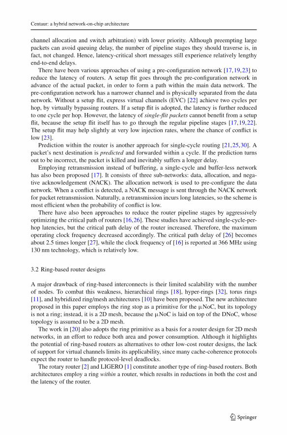
Even though Centaur’s µNoC uses primitive building blocks from ring-based interconnectarchitectures, the topology employed is a 2D mesh. Hence, to avoid confusion, rather thanusing the terms ring stop and ring buffer (see Sect. 2), we use the equivalent terms µNoCstop and µNoC buffer, respectively. The topology of Centaur routers assumed in this work isshown in Fig. 2. A box indicates a Centaur router and a triangle indicates a µNoC stop. Dueto lack of space, Fig. 2 shows a 4×4 mesh, but an 8×8 mesh is assumed in our experiments.The topology of DNoC is also assumed to be a 2D mesh. All the inter-router links are sharedbetween the µNoC and DNoC. Hence, the µNoC is not physically separated from the DNoC;the two networks are fused together.
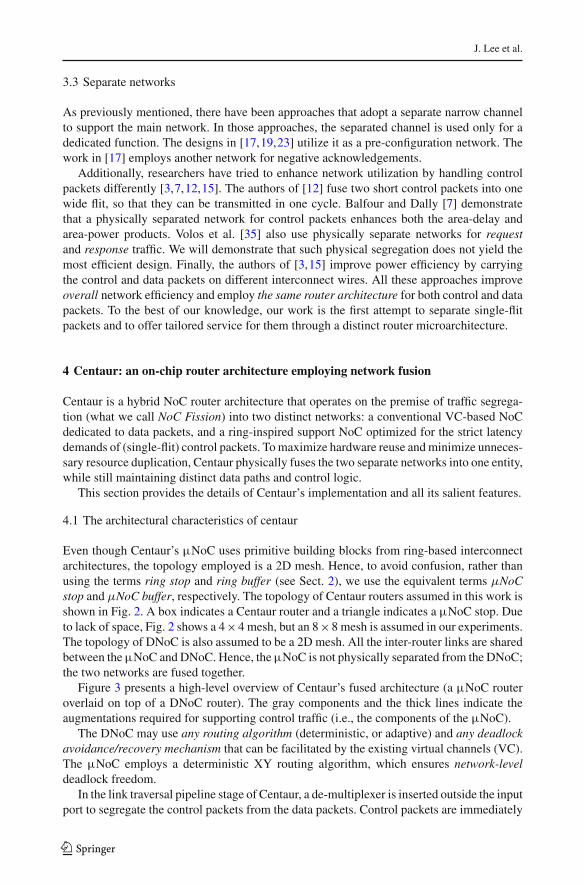
Figure 3 presents a high-level overview of Centaur’s fused architecture (a µNoC routeroverlaid on top of a DNoC router). The gray components and the thick lines indicate theaugmentations required for supporting control traffic (i.e., the components of the µNoC).
The DNoC may use any routing algorithm (deterministic, or adaptive) and any deadlockavoidance/recovery mechanism that can be facilitated by the existing virtual channels (VC).The µNoC employs a deterministic XY routing algorithm, which ensures network-leveldeadlock freedom.
In the link traversal pipeline stage of Centaur, a de-multiplexer is inserted outside the inputport to segregate the control packets from the data packets. Control packets are immediately
123
Centaur: a hybrid network-on-chip architecture
Fig. 2 The topology of theµNoC assumed in this work. Abox denotes a Centaur router anda triangle denotes a µNoC stop
Fig. 3 A high-level block diagram of the fused Centaur microarchitecture. Grey components and thick linesdesignate the additional logic of the µNoC used to support single-flit control packets
forwarded to the next node in the same dimension by completely bypassing the router. Thisforwarding continues until the control packet reaches either its destination node, or a junctionwhere it needs to transfer to a perpendicular direction (i.e., change travel dimension). If acontrol packet requires to change its direction (dimension), then the packet is sent inside theregular input port of the router and is stored in a special FIFO, designated by the name “Int.Buf.” (Intermediate Buffer) in Fig. 3. Data packets continue their regular path through the
123
J. Lee et al.
(a) (b) (c)
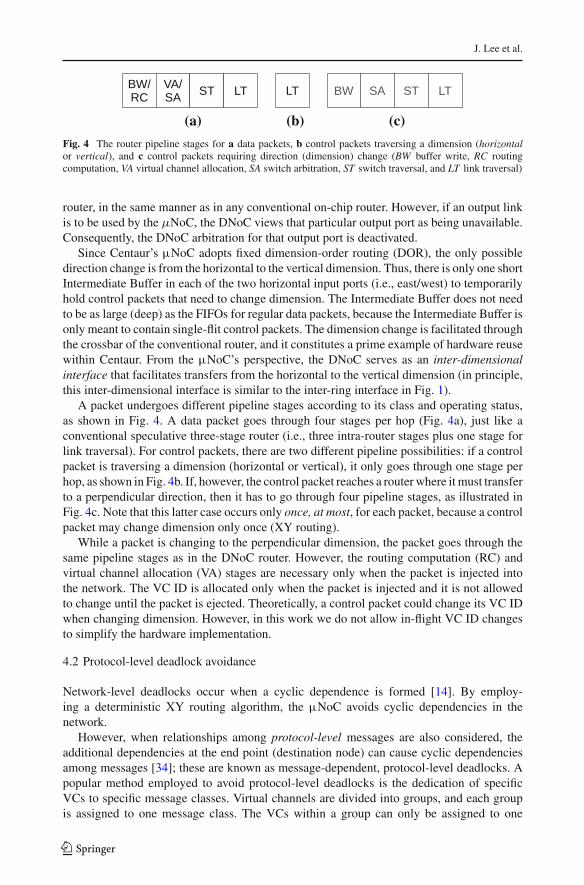
Fig. 4 The router pipeline stages for a data packets, b control packets traversing a dimension (horizontalor vertical), and c control packets requiring direction (dimension) change (BW buffer write, RC routingcomputation, VA virtual channel allocation, SA switch arbitration, ST switch traversal, and LT link traversal)
router, in the same manner as in any conventional on-chip router. However, if an output linkis to be used by the µNoC, the DNoC views that particular output port as being unavailable.Consequently, the DNoC arbitration for that output port is deactivated.
Since Centaur’s µNoC adopts fixed dimension-order routing (DOR), the only possibledirection change is from the horizontal to the vertical dimension. Thus, there is only one shortIntermediate Buffer in each of the two horizontal input ports (i.e., east/west) to temporarilyhold control packets that need to change dimension. The Intermediate Buffer does not needto be as large (deep) as the FIFOs for regular data packets, because the Intermediate Buffer isonly meant to contain single-flit control packets. The dimension change is facilitated throughthe crossbar of the conventional router, and it constitutes a prime example of hardware reusewithin Centaur. From the µNoC’s perspective, the DNoC serves as an inter-dimensionalinterface that facilitates transfers from the horizontal to the vertical dimension (in principle,this inter-dimensional interface is similar to the inter-ring interface in Fig. 1).
A packet undergoes different pipeline stages according to its class and operating status,as shown in Fig. 4. A data packet goes through four stages per hop (Fig. 4a), just like aconventional speculative three-stage router (i.e., three intra-router stages plus one stage forlink traversal). For control packets, there are two different pipeline possibilities: if a controlpacket is traversing a dimension (horizontal or vertical), it only goes through one stage perhop, as shown in Fig. 4b. If, however, the control packet reaches a router where it must transferto a perpendicular direction, then it has to go through four pipeline stages, as illustrated inFig. 4c. Note that this latter case occurs only once, at most, for each packet, because a controlpacket may change dimension only once (XY routing).
While a packet is changing to the perpendicular dimension, the packet goes through thesame pipeline stages as in the DNoC router. However, the routing computation (RC) andvirtual channel allocation (VA) stages are necessary only when the packet is injected intothe network. The VC ID is allocated only when the packet is injected and it is not allowedto change until the packet is ejected. Theoretically, a control packet could change its VC IDwhen changing dimension. However, in this work we do not allow in-flight VC ID changesto simplify the hardware implementation.
4.2 Protocol-level deadlock avoidance
Network-level deadlocks occur when a cyclic dependence is formed [14]. By employ-ing a deterministic XY routing algorithm, the µNoC avoids cyclic dependencies in thenetwork.
However, when relationships among protocol-level messages are also considered, theadditional dependencies at the end point (destination node) can cause cyclic dependenciesamong messages [34]; these are known as message-dependent, protocol-level deadlocks. Apopular method employed to avoid protocol-level deadlocks is the dedication of specificVCs to specific message classes. Virtual channels are divided into groups, and each groupis assigned to one message class. The VCs within a group can only be assigned to one
123
Centaur: a hybrid network-on-chip architecture
class of messages. The group of VCs dedicated to a class is known as a virtual network.This terminology is borrowed from the GEMS simulator [24], which is part of our full-system evaluation framework. Since each VC has its dedicated buffer in every router, itis never blocked by other message classes. By dedicating VCs to message classes, cyclicdependencies among message classes are broken.
In the proposed router, the DNoC has dedicated VC buffers, but the µNoC does not.Looking at Fig. 3, one can see that there is only one µNoC Buffer per input port, which isshared by all message classes served by the µNoC. In other words, all message classes thatsend single-flit control messages are served by the µNoC for the transfers of their controlmessages. A packet in the µNoC may be blocked by packets of other message classes, whichmay lead to a protocol-level deadlock. A naive way to resolve such protocol-level deadlocksis to put more µNoC Buffers in parallel, just like VC buffers are arranged within the DNoC.However, considering the fact that buffers dominate the area of on-chip routers [28], theiroverhead could become excessive.
Instead, this paper proposes a simple time-out mechanism exploiting the µNoC’s inter-action with the DNoC: if a packet in the µNoC cannot proceed to the next router (hop) fora period longer than a threshold, the packet is absorbed into the DNoC (i.e., extracted fromtheµNoC). More specifically, the control packets will be absorbed in the existing VC buffersof their respective message class within the DNoC. Those buffers are already present in theDNoC, since they are used by the data packets of the same message class. Indeed, thereare message classes in certain cache-coherence protocols that make use of both single-flitcontrol messages and multi-flit data messages [35]. As the DNoC is guaranteed to be freefrom protocol-level deadlocks (due to the segregation of message classes into distinct VCbuffers), the absorption from the µNoC to the DNoC will break any protocol-level deadlockwithin the µNoC.
In the case of message classes consisting solely of control packets, their respective VCbuffer within the DNoC may be made arbitrarily shallow (single-flit depth), since it will onlybe used in the presence of a protocol-level deadlock situation. Under normal operation, thecontrol packets are transferred entirely through the µNoC.
Hence, if a packet in a µNoC Buffer of the µNoC is unable to proceed to the µNoCBuffer of the next router, it is forwarded to the VC buffer of its corresponding message classwithin the DNoC of the next router, if the VC buffer is available. Additionally, all packetsin the µNoC and Intermediate Buffers are given the chance to move forward to the nextrouter, even if they are not at the head of the buffers. Specifically, the head/tail pointers of theµNoC and Intermediate Buffers (both buffers have a shallow depth of 2 flits) can deliberatelyviolate FIFO order when the time-out mechanism is triggered, in order to allow any blockedsingle-flit packet to proceed, irrespective of its position in the buffer. The hardware overheadof allowing both single-flit packets in the buffers to move forward is reasonable (as will bedemonstrated in the hardware evaluation of Sect. 5.3).
Identifying the actual threshold value requires experimentation. Since the DNoC exhibitshigher latency per hop (in processing packets) than the µNoC, the threshold should be highenough to prevent false positives. At the same time, too high a threshold would result inlong delay for the deadlock recovery process. To keep the hardware overhead of the time-outcounter at reasonable levels, we chose a threshold value of 64 (6-bit counter). It is worth notingthat the protocol-level deadlock mechanism was never triggered in any of our simulationsand there was never a case of protocol-level deadlock observed. The reason for this behavioris that—in practice—the probability of protocol-level deadlocks occurring in the µNoC isnegligible, so the time-out mechanism will most probably never be triggered when usingreal applications in a real-world environment. Regardless, since there is still a theoretically
123
J. Lee et al.
non-zero probability that a protocol-level deadlock situation may arise within the µNoC, themechanism is there to guarantee functional correctness.
The proposed time-out mechanism is one type of progressive deadlock recovery mecha-nisms [14]. In such schemes, the network consists of the deadlock susceptible network and thedeadlock recovery network [31]. Upon detection of a potential deadlock situation, a packetinvolved in the deadlock is granted use of the recovery network. It has been formally proventhat progressive recovery mechanisms resolve all types of deadlocks when the following twoconditions are met [6,31]: (1) the recovery network is free from deadlocks, and (2) in each andevery deadlock situation, there exists at least one packet that is granted access to the recoverynetwork. Other obvious conditions are omitted for brevity. Interested readers may refer tothe original paper [6]. Since the DNoC serves as the recovery network in Centaur, the firstcondition is satisfied if the DNoC is free from deadlocks (e.g., by employing a deadlock-freerouting algorithm). The second condition is satisfied by the fact that the time-out mechanismgives every flit in the µNoC buffers (µNoC and Intermediate Buffers) the chance to moveforward and enter the recovery network. A formal proof that the above-mentioned two condi-tions are satisfied in the Centaur architecture is found in Appendix I. Thus, any protocol-leveldeadlocks are guaranteed to be broken by the proposed time-out mechanism.
When the time-out mechanism is triggered, the ordered delivery of packets may be violatedin the absence of an appropriate mechanism. This may either complicate the coherenceprotocol, or the system may need to rely on reordering buffers in the network interfacecontroller. However, in the case of Centaur, the solution to this issue is fairly simple, becauseboth the µNoC and DNoC employ a conventional XY routing algorithm. Consequently, allpackets follow the same path from a particular source to a particular destination, regardlessof whether they traverse the µNoC, or the DNoC. Therefore, a simple solution to maintainorder is as follows: any control packet traversing the µNoC checks (through a flag) to seewhether a control packet belonging to the same class is stored in the DNoC (as a result of thetime-out mechanism). If there is such a packet in the DNoC, the µNoC stalls until the packetin the DNoC departs (resetting the flag). In this fashion, control packets of a message classtraversing the µNoC can never overtake a packet that has been absorbed in the DNoC. Itshould be noted here that the time-out mechanism is triggered very rarely, when a protocol-level deadlock is suspected. Thus, even if an ordering mechanism adds some performanceoverhead, the overall impact will be imperceptible, due to the rarity of the mechanism’s use.
The order violation issue is more complicated if the DNoC employs an adaptive routingalgorithm. However, in such cases, packet order may not be preserved even between datapackets within the DNoC itself, since different packets may take different paths. Hence, theDNoC must maintain the packet order by using an additional mechanism, such as sequencenumbering, or reordering buffers. Similarly, the packet order of the µNoC may also bepreserved by reusing the same mechanism.
5 Experimental evaluation
5.1 Simulation framework
Our evaluation approach is double-faceted, utilizing (a) synthetic traffic patterns, and (b)real application workloads running in an execution-driven, full-system simulation envi-ronment. We employ Wind River’s Simics,2 extended with the Wisconsin Multifacet
2 Wind River Systems: http://www.windriver.com/
123
Centaur: a hybrid network-on-chip architecture
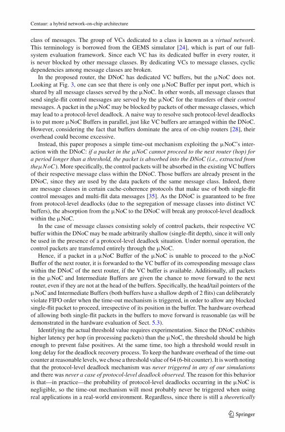
Table 2 Simulated systemparameters
Parameter Value
Processors x86 Pentium 4
Number of processors 64
L1 cache 32 KB, 4-way, 64 B line
L2 cache (shared) NUCA, 1 MB, 8-way, 128 B line
Main memory 2 GB SDRAM
L2 cache policy Non-inclusive
L1 hit latency 3 cycles
L2 hit latency 6 cycles
Directory latency 80 cycles
Memory latency 300 cycles
Operating System Linux Fedora
Topology 8 × 8 mesh
Flit width 128 bits
Virtual networks 3
Pipeline stages 3 (+1 for link traversal)
Buffer size 4 flits per VC(One of the VCbuffers inCentaur’s DNoChas a depth ofonly 1 flit; seetext for details)
Intermediate buffer size 2 flits
GEMS simulator [24] and GARNET [4], a cycle-accurate NoC simulator. Without lossof generality, all simulations assume deterministic XY routing for all packets (control anddata).
Synthetic traffic patterns are initially used in order to stress the evaluated designs andisolate their inherent network attributes. For synthetic simulations, GARNET is utilized ina “network-only” mode, with Simics and GEMS detached. Uniform random, hotspot, andbit-complement traffic is then injected into the network. In hotspot traffic, 20 % of the nodesreceive four times as many packets as the others. In bit-complement traffic, a node at (x, y)
sends packets to a node at (k − x − 1, k − y − 1) [33], where k = 8 in our experiments.The GARNET simulator cycle-accurately models the micro-architecture of the routers. Alldesigns under investigation in this paper were implemented within GARNET.
To assess the impact of Centaur on overall system performance, we then simulate a 64-core tiled CMP system (in an 8 × 8 mesh) within the aforementioned full-system simu-lation framework. The simulation parameters are given in Table 2. The executed applica-tions are part of the PARSEC benchmark suite [8]. PARSEC is a benchmark suite that con-tains multi-threaded workloads from various emerging applications. All applications use 128threads.
Overall, four different techniques are compared:
Proposed centaur architecture: The full-system simulation framework employs the MOESIdirectory protocol, which requires 3 virtual networks, one of which carries only controlpackets. Technically, since one of the virtual networks in the system carries only controlpackets (i.e., single-flit packets), we can remove the corresponding VC buffer from the
123
J. Lee et al.
DNoC, since the control packets are transferred through the µNoC. However, recall thatthe corresponding VC in the DNoC cannot be completely removed, because it is used whena potential protocol-level deadlock is detected and the control packets are absorbed from theµNoC into the DNoC (as explained in Sect. 4.2). Instead, as previously mentioned, the depthof the particular VC buffer in the DNoC can be arbitrarily reduced to a single flit, because thisbuffer will only be used as an escape channel in the rare case of a protocol-level deadlocksituation within the µNoC. Therefore, the Centaur router used in all our simulations willhave 2 VC buffers of depth 4 and one VC buffer of depth 1 (per input port) in the DNoC.An Intermediate Buffer of depth 2 is also used in each of the East and West input ports(designated by ‘Int. Buf.’ in Fig. 3).
Baseline router [4]: The baseline router is a 3-stage NoC router. This router is slightlymore aggressive than the default, 4-stage GARNET router, by speculatively executing virtualchannel allocation and switch arbitration (VA and SA) in parallel. The baseline router has 3VC buffers per input port, each of depth 4.
Cache-coherence network-on-chip (CCNoC) [35]: This is the most relevant work to Cen-taur. It consists of two physically separate networks: one for requests, and the other forresponses. The former network has 2 VCs and the latter has 1 VC. Since the response net-work only has a single VC, its pipeline is aggressively optimized to just 2 stages, whereasthe number of pipeline stages in the request network is 3.
Express virtual channels (EVC) [22]: EVCs are actually not intended for control packets.However, we regard this work to be a very suitable candidate for supporting low-latencyshort messaging, because it offers sustainable performance without incurring undue hardwareoverhead and without increasing the critical path delay of the router. In our implementationof the EVC architecture, control packets are delivered via EVCs, while data packets aredelivered through regular virtual channels. We also evaluate a design where EVCs are usedfor both control and data packets. Dynamic EVCs are used, and their length can be at most8 in an 8 × 8 tiled topology. We assume that the EVC-augmented router takes two cycles perhop. The original paper [22] mentions that it can achieve one cycle per hop—like Centaur—but it requires a setup flit. Since the latency of the setup flit cannot be shorter than two cyclesper hop, and control messages are single-flit packets (just like setup flits), the latency of suchpackets cannot be shorter than two cycles per hop in the EVC router.
5.2 Evaluating the fused centaur’s performance
Figure 5 shows the average network latency achieved in: (1) the Baseline router, (2) theCCNoC router, (3) the EVC router, and (4) the proposed fused Centaur architecture. Thepercentage of control packets is 70 % of the total number of packets injected during thesimulation (as per Table 1). Note that in this experiment, EVC [22] is used to carry onlycontrol packets.
It is evident from Fig. 5a, b that the zero-load latency of the Baseline and the CCNoCrouters is similar. However, the throughput of CCNoC is better than that of the Baseline andEVC. This is because CCNoC employs two physically separate networks, whereas the others(including Centaur) employ one physical network. EVC and Centaur exhibit lower latencythan both the Baseline and CCNoC routers, because the control packets in EVC and Centaurgo through fewer pipeline stages, regardless of the injection rate. Furthermore, Centaurimproves the throughput as well. From these graphs we can also see that Centaur outperformsall other techniques in terms of both latency and throughput. However, the latency of the data
123
Centaur: a hybrid network-on-chip architecture
0
10
20
30
40
50
0 0.02 0.04 0.06 0.08 0.10 0.12Ave
rag
e la
ten
cy (
cycl
es)
Injection rate (packets/cycle/node)
BaselineCCNoC
EVCCentaur
0
10
20
30
40
50
0 0.02 0.04 0.06 0.08 0.10 0.12Ave
rag
e la
ten
cy (
cycl
es)
Injection rate (packets/cycle/node)
BaselineCCNoC
EVCCentaur
0
10
20
30
40
50
0 0.02 0.04 0.06 0.08 0.10 0.12Ave
rag
e la
ten
cy (
cycl
es)
Injection rate (packets/cycle/node)
BaselineCCNoC
EVCCentaur
(a) (b) (c)
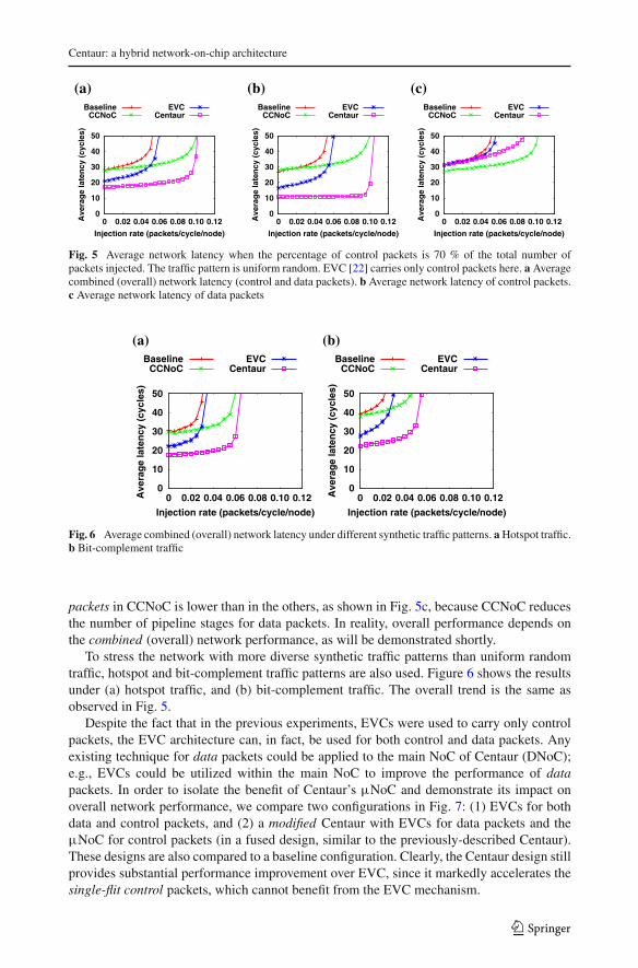
Fig. 5 Average network latency when the percentage of control packets is 70 % of the total number ofpackets injected. The traffic pattern is uniform random. EVC [22] carries only control packets here. a Averagecombined (overall) network latency (control and data packets). b Average network latency of control packets.c Average network latency of data packets
0
10
20
30
40
50
0 0.02 0.04 0.06 0.08 0.10 0.12Ave
rag
e la
ten
cy (
cycl
es)
Injection rate (packets/cycle/node)
BaselineCCNoC
EVCCentaur
0
10
20
30
40
50
0 0.02 0.04 0.06 0.08 0.10 0.12Ave
rag
e la
ten
cy (
cycl
es)
Injection rate (packets/cycle/node)
BaselineCCNoC
EVCCentaur
(a) (b)
Fig. 6 Average combined (overall) network latency under different synthetic traffic patterns. a Hotspot traffic.b Bit-complement traffic
packets in CCNoC is lower than in the others, as shown in Fig. 5c, because CCNoC reducesthe number of pipeline stages for data packets. In reality, overall performance depends onthe combined (overall) network performance, as will be demonstrated shortly.
To stress the network with more diverse synthetic traffic patterns than uniform randomtraffic, hotspot and bit-complement traffic patterns are also used. Figure 6 shows the resultsunder (a) hotspot traffic, and (b) bit-complement traffic. The overall trend is the same asobserved in Fig. 5.
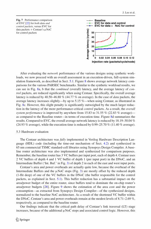
Despite the fact that in the previous experiments, EVCs were used to carry only controlpackets, the EVC architecture can, in fact, be used for both control and data packets. Anyexisting technique for data packets could be applied to the main NoC of Centaur (DNoC);e.g., EVCs could be utilized within the main NoC to improve the performance of datapackets. In order to isolate the benefit of Centaur’s µNoC and demonstrate its impact onoverall network performance, we compare two configurations in Fig. 7: (1) EVCs for bothdata and control packets, and (2) a modified Centaur with EVCs for data packets and theµNoC for control packets (in a fused design, similar to the previously-described Centaur).These designs are also compared to a baseline configuration. Clearly, the Centaur design stillprovides substantial performance improvement over EVC, since it markedly accelerates thesingle-flit control packets, which cannot benefit from the EVC mechanism.
123
J. Lee et al.
Fig. 7 Performance comparisonof EVC [22] for both data andcontrol packets, versus EVC fordata packets + Centaur’s µNoCfor control packets
0
10
20
30
40
50
0 0.02 0.04 0.06 0.08 0.10 0.12Ave
rag
e la
ten
cy (
cycl
es)
Injection rate (packets/cycle/node)
BaselineEVC for data and controlEVC for data + µNoC for control
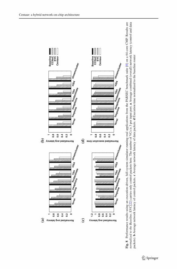
After evaluating the network performance of the various designs using synthetic work-loads, we now proceed with an overall assessment in an execution-driven, full-system sim-ulation framework, as described in Sect. 5.1. Figure 8 shows average network latency com-parisons for the various PARSEC benchmarks. Similar to the synthetic workload results, wecan see in Fig. 8a, b that the combined (overall) latency, and the average latency of con-trol packets, are reduced significantly when using Centaur. Specifically, the overall averagelatency is reduced by 40.50–46.88 % (44.77 % on average). In the case of data packets, theaverage latency increases slightly—by up to 5.15 %—when using Centaur, as illustrated inFig. 8c. However, this slight penalty is significantly outweighed by the much larger reduc-tion in the latency of the more performance-critical control packets. As a result, the overallsystem performance is improved by anywhere from 15.83 to 31.55 % (22.83 % average)—as compared to the Baseline router—in terms of execution time. Figure 8d summarizes theresults. Compared to EVC, the overall average network latency is reduced by 18.19–30.04 %(24.93 % average), while the execution time is reduced by 0.99–25.70 % (11.40 % average).
5.3 Hardware evaluation
The Centaur architecture was fully implemented in Verilog Hardware Description Lan-guage (HDL) code (including the time-out mechanism of Sect. 4.2) and synthesized in65 nm commercial TSMC standard-cell libraries using Synopsys Design Compiler. A base-line router architecture was also implemented and synthesized for comparison purposes.Remember, the baseline router has 3 VC buffers per input port, each of depth 4. Centaur uses2 VC buffers of depth 4 and 1 VC buffer of depth 1 (per input port) in the DNoC, and anIntermediate Buffer (‘Int. Buf.’ in Fig. 3) of depth 2 in each of the east and west input ports.
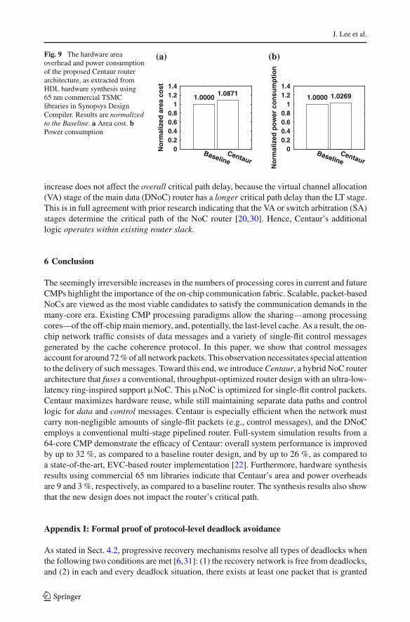
Centaur’s area and power overheads are actually quite low, because the overhead of theIntermediate Buffers and the µNoC stops (Fig. 3) are mostly offset by the reduced depth(1-flit deep) of one of the VC buffers in the DNoC (the buffer responsible for the controlpackets, as explained in Sect. 5.1). This buffer reduction has a substantial impact on thearea/power budget of the entire router, since buffers tend to dominate the on-chip router’sarea/power budgets [28]. Figure 9 shows the estimation of the area cost and the powerconsumption—as extracted from Synopsys Design Compiler—of the synthesized designs,normalized to the baseline NoC architecture. As a result of the shortened VC buffer withinthe DNoC, Centaur’s area and power overheads remain at the modest levels of 8.71–2.69 %,respectively, as compared to the baseline router.
Our findings indicate that the critical path delay of Centaur’s link traversal (LT) stageincreases, because of the additional µNoC stops and associated control logic. However, this
123
Centaur: a hybrid network-on-chip architecture
0
0.2
0.4
0.6
0.8 1
ferr
etfr
eqm
inesw
aptio
nsfluid
anim
ate
vips
x264
stre
amcl
uste
r
Normalized avg latency
0
0.2
0.4
0.6
0.8 1
ferr
etfr
eqm
inesw
aptio
nsfluid
anim
ate
vips
x264
stre
amcl
uste
r
Normalized avg latency
Bas
elin
eC
CN
oC
EV
CC
enta
ur
(a)
(b)
0 0
.2 0
.4 0
.6 0
.8 1 1
.2
ferr
etfr
eqm
inesw
aptio
nsfluid
anim
ate
vips
x264
stre
amcl
uste
r
Normalized avg latency
0
0.2
0.4
0.6
0.8 1
ferr
etfr
eqm
inesw
aptio
nsfluid
anim
ate
vips
x264
stre
amcl
uste
r
Normalized execution time
Bas
elin
eC
CN
oC
EV
CC
enta
ur
(c)
(d)
Fig
.8Pe
rfor
man
cere
sults
usin
gan
exec
utio
n-dr
iven
,ful
l-sy
stem
sim
ulat
orru
nnin
gre
alap
plic
atio
nsfr
omth
ePA
RSE
Cbe
nchm
ark
suite
[8]
ona
64-c
ore
CM
P.R
esul
tsar
eno
rmal
ized
toth
eB
asel
ine.
EV
C[2
2]ca
rrie
son
lyco
ntro
lpac
kets
here
.The
num
ber
ofV
Cs
is3
per
inpu
tpor
t.a
Ave
rage
com
bine
d(o
vera
ll)ne
twor
kla
tenc
y(c
ontr
olan
dda
tapa
cket
s).b
Ave
rage
netw
ork
late
ncy
ofco
ntro
lpac
kets
.cA
vera
gene
twor
kla
tenc
yof
data
pack
ets.
dE
xecu
tion
time
norm
aliz
edto
the
base
line
rout
er
123
J. Lee et al.
Fig. 9 The hardware areaoverhead and power consumptionof the proposed Centaur routerarchitecture, as extracted fromHDL hardware synthesis using65 nm commercial TSMClibraries in Synopsys DesignCompiler. Results are normalizedto the Baseline. a Area cost. bPower consumption
0 0.2 0.4 0.6 0.8
1 1.2 1.4
BaselineCentaur
No
rmal
ized
are
a co
st
1.0000 1.0871
0 0.2 0.4 0.6 0.8
1 1.2 1.4
BaselineCentaur
No
rmal
ized
po
wer
co
nsu
mp
tio
n
1.0000 1.0269
(a) (b)
increase does not affect the overall critical path delay, because the virtual channel allocation(VA) stage of the main data (DNoC) router has a longer critical path delay than the LT stage.This is in full agreement with prior research indicating that the VA or switch arbitration (SA)stages determine the critical path of the NoC router [20,30]. Hence, Centaur’s additionallogic operates within existing router slack.
6 Conclusion
The seemingly irreversible increases in the numbers of processing cores in current and futureCMPs highlight the importance of the on-chip communication fabric. Scalable, packet-basedNoCs are viewed as the most viable candidates to satisfy the communication demands in themany-core era. Existing CMP processing paradigms allow the sharing—among processingcores—of the off-chip main memory, and, potentially, the last-level cache. As a result, the on-chip network traffic consists of data messages and a variety of single-flit control messagesgenerated by the cache coherence protocol. In this paper, we show that control messagesaccount for around 72 % of all network packets. This observation necessitates special attentionto the delivery of such messages. Toward this end, we introduce Centaur, a hybrid NoC routerarchitecture that fuses a conventional, throughput-optimized router design with an ultra-low-latency ring-inspired support µNoC. This µNoC is optimized for single-flit control packets.Centaur maximizes hardware reuse, while still maintaining separate data paths and controllogic for data and control messages. Centaur is especially efficient when the network mustcarry non-negligible amounts of single-flit packets (e.g., control messages), and the DNoCemploys a conventional multi-stage pipelined router. Full-system simulation results from a64-core CMP demonstrate the efficacy of Centaur: overall system performance is improvedby up to 32 %, as compared to a baseline router design, and by up to 26 %, as compared toa state-of-the-art, EVC-based router implementation [22]. Furthermore, hardware synthesisresults using commercial 65 nm libraries indicate that Centaur’s area and power overheadsare 9 and 3 %, respectively, as compared to a baseline router. The synthesis results also showthat the new design does not impact the router’s critical path.
Appendix I: Formal proof of protocol-level deadlock avoidance
As stated in Sect. 4.2, progressive recovery mechanisms resolve all types of deadlocks whenthe following two conditions are met [6,31]: (1) the recovery network is free from deadlocks,and (2) in each and every deadlock situation, there exists at least one packet that is granted
123
Centaur: a hybrid network-on-chip architecture
access to the recovery network. The following theorems prove that these two conditions aresatisfied in the Centaur architecture and, thus, any protocol- level deadlocks are guaranteedto be broken by the proposed time-out mechanism.
Theorem 1 The deadlock freedom of the DNoC is not affected by the µNoC.
Proof Although the inter-router links are shared between the DNoC and the µNoC, the latterhas its own buffers (µNoC Buffer and Intermediate Buffer). Therefore, the µNoC does notaffect the deadlock freedom of the DNoC, because the packets in the µNoC do not block anypackets in the DNoC. ��
Theorem 2 The time-out mechanism enables every packet in a deadlock situation to havethe opportunity to access the recovery network.
Proof When a protocol-level deadlock occurs (or is suspected), all the packets in the µNoCbuffers (µNoC and Intermediate Buffers) are given the chance to escape from the deadlock.As mentioned in Sect. 4.2, even if a packet is not at the head of the buffer, it is also given thesame opportunity. ��
Corollary 1 All dependencies among the various message classes involved in deadlock sit-uations are broken by the time-out mechanism.
Proof Dependencies among message classes can, indeed, be created in the µNoC buffers,whereas there are no such dependencies in the DNoC. In the µNoC, a packet may be blockedby a preceding packet that belongs to a different message class. When the time-out mechanismis triggered, packets are no longer blocked by preceding packets in the µNoC, because theyare forwarded to the DNoC, and the head packet does not block the following packet(s) inthe same buffer. ��
One drawback of this mechanism is that the packet order might be reversed. To preservepacket order, control packets should leave each router in the order of arrival, regardless ofwhich network (µNoC or DNoC) they arrive through. Packets with the same input-outputport mappings should be ordered. As a hardware implementation of packet ordering, weintroduce a sequence numbering mechanism within the router. Note that this mechanism isaccounted for in the area/power/timing evaluation of Sect. 5.3.
For every pair of input and output ports, two counters are maintained for each VC (mes-sage class) in the DNoC, which makes use of control packets. The ‘Head’ counter indicatesthe order of arriving packets and the ‘Tail’ counter indicates the order of departing pack-ets. When a control packet arrives at a router, it is stored either in the µNoC Buffer, orthe Intermediate Buffer, or a VC buffer within the DNoC. Irrespective of which buffer itis stored into, a sequence number is given. The sequence number is equal to ‘Head’ andthe ‘Head’ counter is subsequently increased by one. The packet can leave only when itssequence number matches the ‘Tail’ counter. After the packet departs, ‘Tail’ is increased byone.
However, the sequence numbering raises additional dependencies within a router, whichmay incur deadlocks. The following theorem proves that deadlocks do not happen.
Theorem 3 Deadlock freedom is not affected by the additional dependencies created by thesequence numbering mechanism.
123
J. Lee et al.
Proof Corollary 1 proves that there are no dependencies among message classes when thetime-out mechanism is triggered. The additional dependencies caused by the sequence num-bering mechanism are only within the same message class (VC). Therefore, the additionaldependencies do not cause any packet to be blocked by other message classes. In addition,since the dependencies are created based on the order of arrival (i.e., the dependencies are,essentially, ordered), they do not form any cycles. ��
References
1. Abad P, Puente V, Gregorio JA (2013) LIGERO: a light but efficient router conceived for cache-coherentchip multiprocessors. ACM Trans Archit Code Optim 9(4):37:1–37:21.
2. Abad P, Puente V, Gregorio JA, Prieto P (2007) Rotary router: an efficient architecture for cmp intercon-nection networks. In: Proceedings of the 34th annual international symposium on computer architecture,ISCA ’07, pp 116–125.
3. Abousamra A, Melhem R, Jones A (2012) Deja vu switching for multiplane nocs. In: Sixth IEEE/ACMinternational symposium on networks on chip (NoCS), pp 11–18.
4. Agarwal N, Krishna T, Peh LS, Jha N (2009) GARNET: A detailed on-chip network model inside a full-system simulator. In: IEEE international symposium on performance analysis of systems and software.
5. Agarwal N, Peh LS, Jha N (2009), In-network snoop ordering (INSO): snoopy coherence on unorderedinterconnects. In: Proceedings of the 15th international symposium on high-performance computer, archi-tecture, pp 67–78.
6. Anjan K, Pinkston T, Duato J (1996) Generalized theory for deadlock-free adaptive wormhole routing andits application to disha concurrent. In: Proceedings of IPPS ’96. The 10th international parallel processingsymposium, pp 815–821.
7. Balfour J, Dally WJ (2006) Design tradeoffs for tiled CMP on-chip networks. In: Proceedings of the 20thannual international conference on supercomputing, pp 187–198.
8. Bienia C (2011) Benchmarking modern multiprocessors. Ph.D. Thesis, Princeton University.9. Bolotin E, Guz Z, Cidon I, Ginosar R, Kolodny A (2007) The power of priority: NoC based distributed
cache coherency. In: Proceedings of the first international symposium on networks-on-chip.10. Bourduas S, Zilic Z (2007) A hybrid ring/mesh interconnect for network-on-chip using hierarchical rings
for global routing. In: Proceedings of the first international symposium on networks-on-chip, pp 195–204.11. Chuang JH, Chao WC (1994) Torus with slotted rings architecture for a cache-coherent multiprocessor.
In: Proceedings of the 1994 international conference on parallel and distributed systems, pp 76–81.12. Das R, Eachempati S, Mishra A, Narayanan V, Das C (2009), Design and evaluation of a hierarchical
on-chip interconnect for next-generation cmps. In: Proceedings of the 15th international symposium onhigh-performance computer, architecture, pp 175–186.
13. Das R, Mutlu O, Moscibroda T, Das C (2009) Application-aware prioritization mechanisms for on-chipnetworks. In: Proceedings of the 42nd annual IEEE/ACM international symposium on microarchitecture,pp 280–291.
14. Duato J, Yalamanchili S, Ni L (2003) Interconnection networks. Margan Kaufmann, San Francisco15. Flores A, Aragon J, Acacio M (2010) Heterogeneous interconnects for energy-efficient message man-
agement in cmps. IEEE Trans Comput 59(1):16–2816. Gratz P, Kim C, McDonald R, Keckler S, Burger D (2006) Implementation and evaluation of on-chip
network architectures. In: Proceedings of international conference on computer design.17. Hayenga M, Jerger NE, Lipasti M (2009) SCARAB: a single cycle adaptive routing and bufferless network.
In: Proceedings of the 42nd annual IEEE/ACM international symposium on microarchitecture.18. Holliday M, Stumm M (1994) Performance evaluation of hierarchical ring-based shared memory multi-
processors. IEEE Trans Comput 43:52–6719. Jerger NDE, Peh LS, Lipasti MH (2008) Circuit-switched coherence. In: Proceedings of the second
ACM/IEEE international symposium on networks-on-chip, pp 193–202.20. Kim J (2009) Low-cost router microarchitecture for on-chip networks. In: Proceedings of the 42nd annual
IEEE/ACM international symposium on microarchitecture, pp 255–266.21. Kim J, Nicopoulos C, Park D (2006) A gracefully degrading and energy-efficient modular router archi-
tecture for on-chip networks. SIGARCH Comput Archit News 34(2):4–1522. Kumar A, Peh LS, Kundu P, Jha NK (2007) Express virtual channels: towards the ideal interconnection
fabric. In: Proceedings of the 34th annual international symposium on computer architecture.
123
Centaur: a hybrid network-on-chip architecture
23. Kumary A, Kunduz P, Singhx A, Peh LS, Jhay N (2007) A 4.6Tbits/s 3.6 GHz single-cycle NoC routerwith a novel switch allocator in 65 nm CMOS. In: Proceedings of the 25th international conference oncomputer design, pp 63–70.
24. Martin MMK, Sorin DJ, Beckmann BM, Marty MR, Xu M, Alameldeen AR, Moore KE, Hill MD, WoodDA (2005) Multifacet’s general execution-driven multiprocessor simulator (gems) toolset. SIGARCHComput Archit News 33:2005
25. Matsutani H, Koibuchi M, Amano H, Yoshinaga T (2009), Prediction router: yet another low latency on-chip router architecture. In: Proceedings of the IEEE 15th international symposium on high performancecomputer, architecture, pp 367–378.
26. Mullins R, West A, Moore S (2004), Low-latency virtual-channel routers for on-chip networks. In:Proceedings of the 31st, annual international symposium on computer architecture, p 188.
27. Mullins R, West A, Moore S (2006) The design and implementation of a low-latency on-chip network.In: Proceedings of Asia and South Pacific conference on design automation, p 6.
28. Nicopoulos C, Park D, Kim J, Vijaykrishnan N, Yousif M, Das C (2006) Vichar: a dynamic virtualchannel regulator for network-on-chip routers. In: 39th annual IEEE/ACM international symposium onmicroarchitecture, pp 333–346.
29. Park C, Badeau R, Biro L, Chang J, Singh T, Vash J, Wang B, Wang T (2010) A 1.2 TB/s on-chip ringinterconnect for 45nm 8-core enterprise Xeon processor. In: Proceedings of IEEE international solid-statecircuits conference digest of technical papers, pp 180–181.
30. Peh LS, Dally WJ (2001), A delay model and speculative architecture for pipelined routers. In: Proceedingsof the 7th international symposium on high-performance computer, architecture, p 255.
31. Pinkston T (1999) Flexible and efficient routing based on progressive deadlock recovery. IEEE TransComput 48(7):649–669
32. Sibai F (2008) Adapting the hyper-ring interconnect for many-core processors. In: International sympo-sium on parallel and distributed processing with applications, pp 649–654.
33. Singh A, Dally W, Towles B, Gupta A (2004) Globally adaptive load-balanced routing on tori. ComputArchit Lett 3(1):2
34. Song YH, Pinkston T (2003) A progressive approach to handling message-dependent deadlock in parallelcomputer systems. IEEE Trans Parallel Distrib Syst 14(3):259–275
35. Volos S, Seiculescu C, Grot B, Pour N, Falsafi B, De Micheli G (2012) Ccnoc: Specializing on-chip inter-connects for energy efficiency in cache-coherent servers. In: Sixth IEEE/ACM international symposiumon networks on chip (NoCS), pp 67–74.
123