Embed Size (px)
Citation preview

CENTAUR®
AND HOT RAIL®
INSTALLATIONMANUAL
WARRANTY, TOOLS AND HARDWARE
2802 East Avalon Avenue | Muscle Shoals, AL 35661Ph / 800-348-7787 or 256-248-2556
Email / [email protected] | Web / www.centaurhorsefence.comP/N 306001 Rev 0117

2
30 Year Manufacturers WarrantyTHIS LIMITED WARRANTY is given by Centaur® Fencing Systems, a division of E. S. Robbins Corporation, (“Centaur”) whose address is 2802 East Avalon Avenue, Muscle Shoals, Alabama, 35661, to you, the original retail purchaser of a Fence System manufactured by Centaur. The Product Warranty Registration must be returned to Centaur within 60 days of purchase in order to receive coverage under this warranty.
WHAT THE WARRANTY COVERS AND FOR HOW LONG: For a period of thirty (30) years, commencing on the date that you received the purchased Centaur® Rail, Centaur® Line Post Brackets, Inside Corner Roller, One and Two-Way Barrel Tensioners Sure-Hook® Termination Bracket, or Sure-Hook® Splice Buckle herein after as (Rail /Components), Centaur will deliver new Rail/Components adequate to replace any defective Rail/Components for the Replacement Price as described. If Rail/Components contain any defect which is a direct result of the material or the workmanship used in manufacturing, the Rail/Components will be a prorated replacement.
WHAT THIS WARRANTY DOES NOT COVER: This warranty does NOT cover any of the following:
A. Damage to, or defect in, the Rail/Components resulting from fires, floods, storms, accidents, acts of God, or from alteration, misuse, improper care, or abuse of the Fence by any person, animal or foreign object whatsoever.
B. Installation of the Fence or of the replacement Rail/Components, or damage or defects resulting, directly or indirectly, from any act or omission in the installation of the Rail/Components, regardless of whether the Rail/Components is installed by an individual approved by Centaur or installed by any other individual in compliance with specifications and requirements provided by or on behalf of Centaur.
C. Damage to real property, personal property, or animals, livestock, or any other incidental or consequential damages arising out of any defect of materials or workmanship in the manufacturing of the Fence or out of any act, omission, representation, or warranty of Centaur its agents, employees, or servants.
D. Defects or damage in or to the brace assemblies and/or the installation thereof.
E. Rust, corrosion, normal weathering or discoloration, unless the affected Rail/Component becomes inoperable. Normal weathering is defined as exposure to sunlight and extremes of weather and atmosphere which causes any colored surface to gradually fade, chalk, or accumulate dirt or stains. The severity of any condition depends on the geographical location of the Fence, the cleanliness of the air in the area, and many other influences over which Centaur cannot control. Also, this warranty Does Not cover labor or labor related charges.
F. Centaur reserves the right to discontinue or modify any of its products, including replacement Rail/Components as well as color, without notice to the consumer/buyer, nor will Centaur be liable in the event the replacement material may vary in color or gloss in comparison to the original product as a result of normal weathering.
THIS LIMITED WARRANTY APPLIES ONLY TO DEFECTS IN MATERIAL OR WORKMANSHIP
REMEDIES AND LIMITATIONS: Your sole remedy under this Limited Warranty Agreement shall be the replacement of the Rail/Components as set forth above. We will not install the replacement material. TO THE EXTENT PERMITTED BY LAW, CENTAUR EXPRESSLY DISCLAIMS ALL EXPRESSED WARRANTIES EXCEPT FOR THE LIMITED WARRANTY
SET FORTH HEREIN AND EXPRESSLY DISCLAIMS ALL IMPLIED WARRANTIES, INCLUDING, BUT NOT LIMITED TO, THE IMPLIED WARRANTY OF MERCHANTABILITY AND FITNESS FOR A PARTICULAR PURPOSE. CENTAUR SHALL NOT BE LIABLE FOR INCIDENTAL AND CONSEQUENTIAL DAMAGES RESULTING FROM A BREACH OF THIS WARRANTY, ANY OTHER EXPRESSED WARRANTY OR ANY IMPLIED WARRANTY. IF THE LAW DOES NOT PERMIT THE EXCLUSION OF IMPLIED WARRANTIES, CENTAUR HEREBY LIMITS THE DURATION OF ALL IMPLIED WARRANTIES, INCLUDING THE IMPLIED WARRANTIES OF MERCHANTABILITY AND FITNESS FOR A PARTICULAR PURPOSE, TO THIRTY (30) DAYS FROM THE DATE THE FENCE WAS DELIVERED TO YOU.
If, notwithstanding the above provision, there should arise any liability on the part of Centaur for implied warranties of any nature or for express warranties other than as set forth herein or for any act or omission of Centaur or its agents or employees, such liability shall be limited to an amount equal to Two Hundred Fifty and no/100 Dollars ($250.00).
Such liability is fixed as total damages and not as a penalty and this liability shall be complete and exclusive. The provisions of this paragraph shall apply to all loss or damage of whatever nature arising from any act, omission, representation, warranty, agreement of Centaur, its agents or employees, including, but not limited to, loss to personal property and/or livestock or cattle. You acknowledge that it is impractical and extremely difficult to fix actual damages which may arise due to the failure of the Fence. Therefore, you agree to this damages clause if, notwithstanding the provisions hereinabove, there should arise any liability on Centaur other than expressly set forth in this Limited Warranty. SOME STATES DO NOT ALLOW LIMITATIONS ON HOW LONG AN IMPLIED WARRANTY LASTS, SO THE ABOVE LIMITATION MAY NOT APPLY TO YOU.
HOW TO OBTAIN SERVICE: The Product Warranty Registration must be returned to Centaur within 60 days of purchase in order to receive coverage under this warranty. If a problem with the Rail/Components develops during the Warranty Period, call Centaur at (800) 348-7787. Inform the Centaur representative that you have purchased the Fence and are protected under this Warranty. Leave your name, address, telephone number and a description of the nature of the defect with the representative. In addition, you must send a letter stating the information requested above, together with proof of purchase and proof acceptable to Centaur, of actual defect and extent of defect (e.g., pictures or samples), by certified or registered mail to Centaur Fencing Systems, 2802 East Avalon Avenue, Muscle Shoals, AL 35661. Centaur reserves the right to send a representative to inspect any alleged defect in the Rail/Components. Centaur, upon its reasonable determination that a defect in material or workmanship does exist, will deliver the replacement Rail/Components within thirty (30) days of its receipt of the written request and the prorated Replacement Price unless prohibited from doing so by an act of God, strike, boycott, unavailability of parts and materials, or any other activity beyond its control, in which case, Centaur will diligently pursue its obligations hereunder. You may be required to return the defective product at Centaur’s cost. Centaur reserves the right, should it independently select to do so, refund the amount paid by the original owner for the Rail/Components. You will be responsible for all costs of shipping the replacement Rail/Components. Customers outside of North America please contact your dealer for service.
SPECIFIC LEGAL RIGHTS: This Warranty gives you specific legal rights and you may also have other rights which vary from state to state.
ONLY WARRANTIES: THIS IS THE ONLY WARRANTY GIVEN BY CENTAUR FENCING SYSTEMS. YOU HEREBY ACKNOWLEDGE THAT THERE ARE NO GUARANTEES, WARRANTIES, UNDERSTANDINGS OR REPRESENTATIONS MADE BY CENTAUR THAT ARE NOT SET FORTH IN THIS DOCUMENT.

3
Centaur®, The Horse Friendly Fence®, prides itself on providing safer, long lasting containment fence systems.
Due to the high tensile nature of Centaur® fencing systems, proper installation methods presented in this manual must be followed to ensure peak performance and long lasting containment.
Centaur Customer Service must verify that proper installation methods are followed in order to provide warranty coverage and help ensure the optimal safety and product performance of your fence system for years to come.
Register your product warranty online at: http://www.centaurhorsefence.com/warranty
Warranty registration must be submitted to Centaur Customer Service within sixty (60) days of purchase. If you are unable to register online, you may submit the required registration information by US Mail (postmarked within sixty (60) days of purchase).
Please contact Centaur Customer Service at1-800-348-7787 with any questions regarding US Mail registration. By submitting warranty registration through US Mail, you acknowledge the warranty rules and restrictions as outlined in this product manual.
The following information is required for 30-Year Limited Warranty Registration:
Contact Information for Warranty Registrant:• First & Last Name• Email• Phone Number• Address, City, State, Zip Code
Purchase Information:• Dealer/Retailer Name (where product was purchased)• Dated Proof of Purchase (receipt or invoice)• Product Being Registered (Centaur®, Hot Rail®)• Product Label Numbers (located on the lower left of the fence
roll product label)• Number of product rolls purchased• Product Color
Installation Photos: These installation photos allow Centaur Customer Service to assist you with any adjustments that may need to be addressed for the proper function of your fence system. By submitting installation photos, you give Centaur® Fence Systems permission to use the provided images for informational and training purposes only. Customer names and locations will not be shared or sold.
1. Photo(s) of Horizontal Brace Assembly
2. Photo(s) of Corner/Diagonal Brace Assembly
3. Photo(s) showing as much of the finished fence as possible.
The Purchase Information and Installation Photos submitted will be examined by Centaur Customer Service. Once approved, a product warranty will be issued and sent to the contact/address provided for the Warranty Registrant.
Register your product warranty online at: http://www.centaurhorsefence.com/warranty
If unable to register online, you may mail the required30-Year Limited Warranty Registration Information(as stated above) with Photos to:
Centaur® Fencing SystemsAttn: Customer Service2802 E. Avalon AvenueMuscle Shoals, AL 35661
Please contact Centaur Customer Service at 1-800-348-7787 with any questions regarding US Mail registration.
30-Year Limited Warranty Registration Requirements
10
40

4
HARDWARE
Tape Measure - 25 ft. minimum(100 ft. optional)
Utility Knife
Centaur® and Hot Rail® Installation Manual
1/2” DriveLong Handle Ratchet (Max Length 14”)
Marking Pen and Pencil
Hammers, claw and 2 lbs. sledge
Level -2 ft. long
Safety Glassesand Gloves
Power Post Hole Digger(Optional)
1” x 2” x 48” Long Straight Wood for Bracket Template
Drill and 3/8” Drill Bit
8” Lineman Pliers or Wire Cutters
Post Hole Digger -hand heldShovels - spade typeand regular
Colored String, Stakes, and/or Layout Paint
Spinning Jenny

5
MATERIALS
Brace and Line Treated Post4” - 6” dia. by 7.5 to 8 ft. Long
Pre-Mixed Concrete
End and Corner Treated Posts6” - 8” dia. by8 or 9 ft. long
Paint for the posts (optional)
Diagonal Brace Plate orBrace Pin
Termination Loop
Nails or Screws(Straight Runs 3.5” Nails/2.5” Ext. Wood Screw)
Centaur®
FencingCentaur®
Two Piece Line Bracket
T-Bracket
Splice Buckle
Barrel TensionerTwo-Way
Inside Corner Roller
Barrel TensionerOne-Way
Termination Bracket
Undergate Cable
Splice Cover (Does not include wire links or crimping tools)
Wire Links12.5 Gauge
Insulator Pad
Line Tap Connector
6
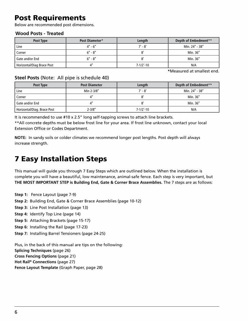
Post RequirementsBelow are recommended post dimensions.
Steel Posts (Note: All pipe is schedule 40)
It is recommended to use #10 x 2.5” long self-tapping screws to attach line brackets.**All concrete depths must be below frost line for your area. If frost line unknown, contact your local Extension Office or Codes Department.
NOTE: In sandy soils or colder climates we recommend longer post lengths. Post depth will always increase strength.
This manual will guide you through 7 Easy Steps which are outlined below. When the installation is complete you will have a beautiful, low maintenance, animal-safe fence. Each step is very important, but THE MOST IMPORTANT STEP is Building End, Gate & Corner Brace Assemblies. The 7 steps are as follows:
Step 1: Fence Layout (page 7-9)
Step 2: Building End, Gate & Corner Brace Assemblies (page 10-12)
Step 3: Line Post Installation (page 13)
Step 4: Identify Top Line (page 14)
Step 5: Attaching Brackets (page 15-17)
Step 6: Installing the Rail (page 17-23)
Step 7: Installing Barrel Tensioners (page 24-25)
Plus, in the back of this manual are tips on the following:Splicing Techniques (page 26)Cross Fencing Options (page 21)Hot Rail® Connections (page 27)Fence Layout Template (Graph Paper, page 28)
7 Easy Installation Steps
Post Type Post Diameter Length Depth of Embedment**
Line Min 2-3/8’’ 7’ - 8’ Min. 24’’ - 38’’
Corner 4’’ 8’ Min. 36’’
Gate and/or End 4’’ 8’ Min. 36’’
Horizontal/Diag. Brace Post 2-3/8’’ 7-1/2’-10 N/A
Wood Posts - Treated
*Measured at smallest end.
Post Type Post Diameter* Length Depth of Embedment**
Line 4’’ - 6’’ 7’ - 8’ Min. 24’’ - 38’’
Corner 6’’ - 8’’ 8’ Min. 36’’
Gate and/or End 6’’ - 8’’ 8’ Min. 36’’
Horizontal/Diag Brace Post 4’’ 7-1/2’-10 N/A

7
Step 1: Fence LayoutCall 811 or visit www.call811.com to have the local utilities department locate and mark all underground lines that may interfere with your Fence Layout.
When determining the Fence Layout there are many things to consider:
• Property Lines
• Approximate Measurements
• Gate Locations & Sizes
• Distance Between Line Posts (8’, 10’, 12’)
• Number of Rails, Spacing Between Rails & Rail Placement (Inside or Outside)
*For a safer fence, we recommend placement of rail on the animal side of line posts.
• End & Gate Bracing Assemblies (Horizontal/Diagonal or Horizontal or Diagonal)
• Corner Bracing Assemblies (Rounded, Double 45 degree or 90 degree)
*For a safer fence, we recommend Rounded or Double 45 degree corner assemblies.
• Types of Terminations (One-Way Tensioner, Termination Loop, Termination Bracket or T-Bracket)
• If area being fenced requires a Two-Way Barrel Tensioner, mark these locations
How much Rail do I need?
Use this formula to calculate how many rolls will be needed for your installation.
______________ x _____________ = _________________ / 660’ = ____________________ Total Footage # of Rails Total Rail Footage # of Rolls Needed
Example: 1315’ x 4 = 5260’ / 660’ = (7.97) 8 Rolls
1A: Design Fence Layout
Using the provided graph paper in the back of this manual, complete your Fence Layout. Be sure to:
• Note all gate locations, sizes & opening direction.
• Mark individual measurements on fence layout.
• Decide on the spacing that will be used between line posts.
• Decide which side of the post you will place your rail.
• Mark all end, gate & corner bracing assemblies locations & types.• Decide on termination types & tensioner locations.

8
1. ROUNDED CORNER with rail on INSIDE of corner posts.
The illustrations below show different options that are recommended when running corners in a typical paddock.
2. ROUNDED CORNER with rail on OUTSIDE of corner posts.
3. Double 45 DEGREE CORNER with rail on INSIDE of line posts.
4. Double 45 DEGREE CORNER with rail on OUTSIDE of corner posts.
Illustration 1-AIllustration 1-A Illustration 1-BIllustration 1-B
Illustration 2-AIllustration 2-A Illustration 2-BIllustration 2-B
Illustration 3-AIllustration 3-A Illustration 3-BIllustration 3-B
Illustration 4-AIllustration 4-A Illustration 4-BIllustration 4-B
9
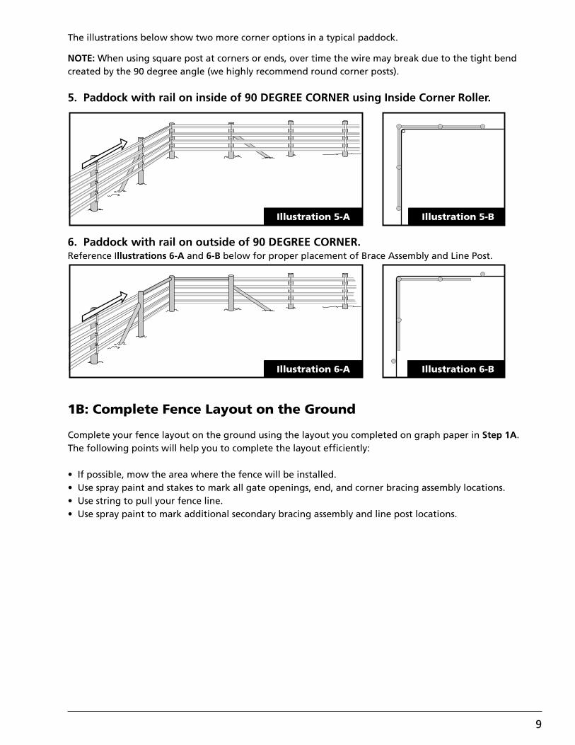
5. Paddock with rail on inside of 90 DEGREE CORNER using Inside Corner Roller.
6. Paddock with rail on outside of 90 DEGREE CORNER.Reference Illustrations 6-A and 6-B below for proper placement of Brace Assembly and Line Post.
The illustrations below show two more corner options in a typical paddock.
NOTE: When using square post at corners or ends, over time the wire may break due to the tight bend created by the 90 degree angle (we highly recommend round corner posts).
1B: Complete Fence Layout on the Ground
Complete your fence layout on the ground using the layout you completed on graph paper in Step 1A. The following points will help you to complete the layout efficiently:
• If possible, mow the area where the fence will be installed.• Use spray paint and stakes to mark all gate openings, end, and corner bracing assembly locations.• Use string to pull your fence line.• Use spray paint to mark additional secondary bracing assembly and line post locations.
Illustration 5-AIllustration 5-A Illustration 5-BIllustration 5-B
Illustration 6-AIllustration 6-A Illustration 6-BIllustration 6-B

10
Step 2: Building End, Gate & Corner Brace Assemblies
Please remember this is the foundation of your fence, so the extra time and construction on this step will result in a Safer and Stronger fence.
The following diagrams illustrate the various end, gate and corner brace assemblies that are recommended for installation. The horizontal/diagonal brace and the 5-post corner are the strongest and safest of each assembly type.
NOTES (These notes apply to all brace assemblies):
1. The depth of concrete may vary to frost lines in your area. Consult local codes for details to ensure that depth of concrete is below frost line*.2. Lean post 1/2” - 1” away from direction of pull.3. We recommend to auger a 12” diameter hole minimum with a 18”- 22” bell at bottom of hole. Depth is determined by frost line depth in your area.4. In sandy soils we recommend to auger a 12” diameter hole, 4’ - 5’ deep with a 22” bell diameter.
FENCE TIP: Post depth will always increase strength.
*Ensure depth of concrete is below frost line.
40”
* *
* BELOW FROST LINE
10
HORIZONTAL/DIAGONAL BRACE ASSEMBLYHorizontal/Diagonal Brace Assembly

11
NOTE: • A 5-post corner assembly is much safer for animal containment and puts less strain on the post than a 90 degree corner assembly.• All posts are 6”- 8” x 8’ min. (wood), 4”- 6” x 8’ min. (steel).
NOTE: Underground concrete brace is 9” wide x 12”high.
*Ensure depth of concrete is below frost line.
*Ensure depth of concrete is below frost line.
10
Horizontal Brace Assembly
40
Diagonal Brace Assembly
5-POST CORNER5-Post Corner

12
10
10
DIMENSION WILL VARYDEPENDING ON ANGLE OF
DIAGONAL POST
DIMENSION WILL VARYDEPENDING ON ANGLE OF
DIAGONAL POST
90 Degree Corner
Double 45 Degree Corner

13
Step 3: Line Post Installation
3A: Post Spacing
Line posts can be installed by either augering a hole or by using a hydraulic post driver. A spacing of 8’-12’ is recommended between line posts. Post set closer together will provide a stronger fence. Refer to Illustration 3-A below for more information.
3B: Curving Fence Line
If the fence line has gentle curves, like in the case of following the contour of a driveway, then the fence posts must be reinforced with concrete. Refer to Illustration 3-B for more information. As shown, concrete footings need to be made with the flat face of the concrete facing the OPPOSITE direction of the curve.
26" TO 38"
8’- 12’
54”- 58”
Illustration 3-AIllustration 3-A
Illustration 3-BIllustration 3-B

14
Step 4: Identifying Top Line
4A: Identify Top Line
55”
First Step: Identifying the top line is determining your final post height. In the example above, a post height of 55” has been chosen. Starting on level terrain, mark the first post at 55” and attach a string. Continue along with the string, wrapping it around each post or a small nail may also be used to hold the string in place on each post. Once the string has been pulled from end to end, stand back and make sure the string follows in a gentle, smooth flow. If not, with assistance, move the string up or down to achieve a gentle smooth flow. Do not be concerned that the bottom rail is not always the same distance from the ground. The illustration below shows how a fence should flow along an irregular terrain.
A - Typical 55” post height on level terrain.B - Over abrupt rise of terrain post could be 50” in height.C - Over abrupt fall of terrain post could be 58” in height.D - Typical 55” height on level terrain.
Next: Mark all line posts where the string touches with a lumber crayon or marker. This will be your final post height.
NOTE: If you have excess post above your final post height, this would be the best time to remove it using a chain saw. If you choose to cut off the excess post, it is recommended to slope the top of the post ap-proximately 1”. Make sure the post slopes AWAY from the rail. FENCE TIP: For an improved appearance on end and corner posts it is also recommended to add an addi-tional 1” to the height and cut the posts flat. NOTE: If you plan to paint the posts, this would be the best time, prior to attaching brackets.

15
Step 5: Attaching Brackets
5A: Identifying Bracket Placement
It is important that your rails are spaced evenly as it makes for a better looking fence. The equation below will simplify this step.
X = (H - 5N - B - A) / (N - 1)
X = Space between the railsH = Height of the post (55” is used in this example)N = Number of rails used (4 in this example)B = Clearance below the fence (12” is recommended)A = Distance from the top of the rail to the top of the post (1” in this example)
NOTE: The 1” distance between the top of the rail and the top of the post allows the top bracket to be flush with the top of the post. If you want a little of your post showing above the bracket, then additional space will be required.
The illustration below shows what each letter in the above equation represents. In our example:
X = (55 - 5 x 4 - 12 - 1) / (4 - 1) = 22 / 3 = 7-1/4” between rails
X
A
X
X
H
B

16
5B: Making Bracket Template
Now that we have the spacing figured for the rails, it is time to begin attaching the brackets. Using a T-square or similar device will help to speed up the marking process and eliminate potential mistakes when marking the line posts.
Using a T-square (or similar device) and some tape, mark off the stick to make a template. The top of the first piece of tape should be 7” down from the right angle of the T-square. Refer to the below illustration for clarification. From there, the top of each additional piece of tape should be whatever you figured your rail spacing to be in Step 5A PLUS 5”. So, in the example in 5A, the spacing was figured to be 7-1/4”. 7-1/4” + 5” = 12-1/4”.
NOTE: The TOP of each piece of tape is where the BOTTOM of each bracket should be placed. Refer to the diagram below.
NOTE: Notice that all measurements reference from top downward. This is very important because you identified the flow of your rail earlier and that was achieved using the string on the top of your post.
5C: Marking Post
Using the template made in Step 5B, mark all line posts with a lumber crayon or marker. This will be the location to place the bottom of each bracket as you attach them to your line posts.
NOTE: Be sure to make the mark at the TOP of each piece of tape, otherwise the rails will move up and down.
Tape 4: 31-1/2 + 12-1/4 = 43-3/4” from the right angle.
7”
19-1/4”
31-1/2”
43-3/4”
Tape 1: 7” below the right angle of the T-square
Tape 2: 7 + 12-1/4 = 19-1/4” from the right angle.
Tape 3: 19-1/4 + 12-1/4 = 31-1/2” from the right angle.

17
5D: Attaching Line Brackets to Post
Attach the brackets to the line posts using the marks you made in Step 5C. Nail or screw the bottom of the brackets to the posts, then open the brackets as shown in Illustration 5-A below. Brackets must be square to the post and the rail so that the rail will look smooth and react properly when required to flex. Refer to Illustration 5-B below to see how the brackets should look when the rail is installed.
NOTE: The top nail or screw should NOT be inserted until the rail has been paid/pulled out, inserted into brackets and deemed to be of acceptable quality. Do not overtighten line bracket. A cracked coating will cause the metal core to become exposed and rust over time.
Step 6: Installing the Rail
Important: Be sure to remove and keep the stickers on the rail packaging as the product label numbers will be needed to complete the Warranty Registration.
6A: Terminations
At this point you need to decide how you want to terminate your rails. There are four options:
Option 1: One-Way Barrel Tensioners (see page 24)Option 2: Termination BracketOption 3: Termination LoopOption 4: T-Bracket (for cross fence termination)
NOTE: Terminating one end of your rail will make Step 6B easier to complete.
CENTAUR®/HOT RAIL® TWO-PIECE LINE BRACKET
Rail
LinePost
Illustration 5-B
Centaur®/Hot Rail®
Two-PieceLine Bracket
Illustration 5-AIllustration 5-A Illustration 5-B

18
1013
FOR ANY QUESTIONS OR COMMEN TS, PLEASE CONTACT CEN TAUR HTP FENCING2802 E. Avalon Ave. Muscle Shoals AL, 35661 Phone (256) 248-2403 or toll free 1-800-348-7787
Fax: (256) 248-2418 web: www.centaurhtp.com
Step One:
as a guide and mark the center point for pilot hole locations as shown in Illustration A. Using a 3/8” drill bit, drill pilot holes for all Termination Bracket locations.
Step Two:Measure back approximately 3” on the rail and sliderail into Termination Bracket as shown in Illustration B.Then, using the bracket, bend the rail over as shown inIllustration C.
Step Three:Slide the supplied loop over the bent rail, making sure the gap in the loop is on the same side of the bend as shown in Illustration D. Then, attach the Termination Bracket to thethe post and slide the rail through the bracket as shown inIllustration E.
Step Four:Next, slide the ring over (1) so that it goes in between the bendon the rail and then slide rail into the slot, over the ring (2) asshown in Illustration F. Last, tension the rail from the oppositeend to take up slack as shown in Illustration G.
NOTE: Do NOT overtighten the lag screw. Termination
with slight pressure.
A
B
D
F
C3”
E
G
Option 2: Termination Bracket
Option 1: One-Way Barrel Tensioner (see page 23)
Insulated Hot Rail® Termination Brackets are required for electric Hot Rail® Fence System.
GAP
1
2
Option 2: Termination Bracket
1013
FOR ANY QUESTIONS OR COMMEN TS, PLEASE CONTACT CEN TAUR HTP FENCING2802 E. Avalon Ave. Muscle Shoals AL, 35661 Phone (256) 248-2403 or toll free 1-800-348-7787
Fax: (256) 248-2418 web: www.centaurhtp.com
Step One:
as a guide and mark the center point for pilot hole locations as shown in Illustration A. Using a 3/8” drill bit, drill pilot holes for all Termination Bracket locations.
Step Two:Measure back approximately 3” on the rail and sliderail into Termination Bracket as shown in Illustration B.Then, using the bracket, bend the rail over as shown inIllustration C.
Step Three:Slide the supplied loop over the bent rail, making sure the gap in the loop is on the same side of the bend as shown in Illustration D. Then, attach the Termination Bracket to thethe post and slide the rail through the bracket as shown inIllustration E.
Step Four:Next, slide the ring over (1) so that it goes in between the bendon the rail and then slide rail into the slot, over the ring (2) asshown in Illustration F. Last, tension the rail from the oppositeend to take up slack as shown in Illustration G.
NOTE: Do NOT overtighten the lag screw. Termination
with slight pressure.
A
B
D
F
C3”
E
G
Option 2: Termination Bracket
Option 1: One-Way Barrel Tensioner (see page 23)
Insulated Hot Rail® Termination Brackets are required for electric Hot Rail® Fence System.
GAP
1
2
Option 1: One-Way Barrel Tensioner (see page 24)
Insulated Hot Rail® Termination Brackets are required for electric Hot Rail® Fence System.
Step One:Pilot holes must be drilled first. To do this, use a fence bracket as a guide and mark the center point for pilot hole locations as shown in Illustration A. Using a 3/8” drill bit, drill pilot holes for all Termination Bracket locations.
Step Two:Measure back approximately 3” on the rail and slide rail into Termination Bracket as shown in Illustration B. Then, using the bracket, bend the rail over as shown in Illustration C.
Step Three:Slide the supplied loop over the bent rail, making sure the gap in the loop is on the same side of the bend as shown in Illustration D. Then, attach the Termination Bracket to the post and slide the rail through the bracket as shown in Illustration E.
Step Four:Next, slide the loop over (1) so that it goes in between the bend on the rail and then slide rail into the slot, over the loop (2) as shown in Illustration F. Last, tension the rail from the opposite end to take up slack as shown in Illustration G.
NOTE: Do NOT over-tighten the lag screw. Termination Bracket should fit snug to post, but still be able to move with slight pressure.
NOTE: Some part generations have a hook accessory instead of a loop. Contact Centaur Customer Service with any installation questions 800-348-7787.

19
This option may be used when terminating Hot Rail.
0414
4” L x 1/2” Lag Screw 1” O.D. Washer
[A] [B]
Plastic Spacer
Steel Pin (x 2)[C][D]
Insulator Sleeve (x 2)
[E]
TERMINATION BRACKET: ELECTRICINSTALLATION INSTRUCTIONS
®
FOR ANY QUESTIONS OR COMMEN TS, PLEASE CONTACT CEN TAUR HTP FENCING2802 E. Avalon Ave. Muscle Shoals AL, 35661 Phone (256) 248-2403 or toll free 1-800-348-7787
Fax: (256) 248-2418 web: www.centaurhorsefence.com
Step One:
Step Two:Measure back approximately 6” as shown in Illustration B. Then, using the bracket or similar straight edge as a guide, bend the rail over as shown in Illustration C.
Step Three:Attach the Termination Bracket to the post using the supplied lag screw and washer. Then, (1) hold the two insulator sleeves and plastic spacer in place and (2) slidethe two steel pins through the slot on the bracket, into the sleeves as shown in Illustration D.
NOTE: Make sure the flanged ends of the steel pins are on the top side to prevent the pins from sliding out of the sleeves.
Step Four:Next, slide the bent rail into the bracket with the 6” portion sliding between the insulator sleeves as shown in Illustration E. Last, tension the rail from the opposite end to take up slack as shown in Illustration F.
NOTE: Do NOT overtighten the lag screw. TerminationBracket should fit snug to post, but still be able to movewith slight pressure.
A
B
D
E
C6”
F
HARDWARE INCLUDED FOR HOT RAIL TERMINATION BRACKET
Pilot holes must be drilled first. To do this, use a fencebracket as a guide and mark the center point for pilot holelocations as shown in Illustration A. Using a 3/8” drill bit,drill pilot holes for all Termination Bracket locations.
1
2
flangedends
Hot Rail® Termination BracketInsulated Hot Rail® Termination Brackets must be used with electric Hot Rail® Fence System.
This option may be used when terminating Hot Rail.
0414
4” L x 1/2” Lag Screw 1” O.D. Washer
[A] [B]
Plastic Spacer
Steel Pin (x 2)[C][D]
Insulator Sleeve (x 2)
[E]
TERMINATION BRACKET: ELECTRICINSTALLATION INSTRUCTIONS
®
FOR ANY QUESTIONS OR COMMEN TS, PLEASE CONTACT CEN TAUR HTP FENCING2802 E. Avalon Ave. Muscle Shoals AL, 35661 Phone (256) 248-2403 or toll free 1-800-348-7787
Fax: (256) 248-2418 web: www.centaurhorsefence.com
Step One:
Step Two:Measure back approximately 6” as shown in Illustration B. Then, using the bracket or similar straight edge as a guide, bend the rail over as shown in Illustration C.
Step Three:Attach the Termination Bracket to the post using the supplied lag screw and washer. Then, (1) hold the two insulator sleeves and plastic spacer in place and (2) slidethe two steel pins through the slot on the bracket, into the sleeves as shown in Illustration D.
NOTE: Make sure the flanged ends of the steel pins are on the top side to prevent the pins from sliding out of the sleeves.
Step Four:Next, slide the bent rail into the bracket with the 6” portion sliding between the insulator sleeves as shown in Illustration E. Last, tension the rail from the opposite end to take up slack as shown in Illustration F.
NOTE: Do NOT overtighten the lag screw. TerminationBracket should fit snug to post, but still be able to movewith slight pressure.
A
B
D
E
C6”
F
HARDWARE INCLUDED FOR HOT RAIL TERMINATION BRACKET
Pilot holes must be drilled first. To do this, use a fencebracket as a guide and mark the center point for pilot holelocations as shown in Illustration A. Using a 3/8” drill bit,drill pilot holes for all Termination Bracket locations.
1
2
flangedends

20
Step One:Pilot holes must be drilled �rst. To do this, use a fence bracket as a guide and mark the center point for pilot hole locations as shown in Illustration A. Using a 3/8” drill bit, drill pilot holes for all Termination Bracket locations.
Step Two:Measure back approximately 2-1/2” - 4” on the rail as shown in Illustration B and then bend the rail back as shown in Illustration C.
Step Three:Insert the bent piece of rail into the slot on the Termination Bracket as shown in Illustration D. Make sure the short side of the bent rail is farthest from the mounting hole in the bracket. Once the rail is inserted, slide the provided bent pin into place as shown in the illustration.
Step Four:Attach the Termination Bracket using the supplied lag screw (A) and washer (B) as shown in Illustration E. Once the bracket is attached to the post, tension the rail from the opposite end to take up slack.NOTE: Do NOT overtighten the lag screw. Termination Bracket should �t snug to post, but still be able to move with slight pressure.
A
B
D
E
C21/2” 4”
Step One:Slide rail through loop and bend back 3”- 4” of rail as shownin Illustration B and C.
Wrap rail around postand slide bent portion of rail into loop.
Step Two:
Install a Centaur® bracket as shown in Illustration D andpull tension on rail to pull up tight to post.
Step Three:
B C
D
3” - 4”Option 3: Termination Loop
Option 4: T-Bracket(Cross Fence Termination)
This method cannot be used with electric Hot Rail® Fence System.
This method cannot be used with electric Hot Rail® Fence System.
Step One:Remove existing fence bracket if needed and place T-Bracket over rail as shown in Illustration A. Use the T-Bracket as a template to mark hole locations. Using a 1/4” drill bit, drill pilot holes for all T-Bracket locations.
Step Two:Measure back 3” to 4” from end of both rails as shown in Illustration B and C. NOTE: Bends should be made to create flaps.
NOTE: A horizontal/diagonal brace assembly is required to prevent end post from moving when tension is applied. Refer to Step 2 for bracing assembly instructions (page 10).
This option may be used when terminating Hot Rail.
1013
4” L x 1/2” Lag Screw 1” O.D. Washer
[A] [B]
TERMINATION BRACKET: ELECTRICINSTALLATION INSTRUCTIONS
®
FOR ANY QUESTIONS OR COMMENTS, PLEASE CONTACT CENTAUR HTP FENCING2802 E. Avalon Ave. Muscle Shoals AL, 35661 Phone (256) 248-2403 or toll free 1-800-348-7787
Fax: (256) 248-2418 web: www.centaurhtp.com
Step One:
as a guide and mark the center point for pilot hole locations as shown in Illustration A. Using a 3/8” drill bit, drill pilot holes for all Termination Bracket locations.
Step Two:Measure back approximately 3” on the rail and sliderail into Termination Bracket as shown in Illustration B.Then, using the bracket, bend the rail over as shown inIllustration C.
Step Three:Slide the supplied loop over the bent rail, making sure the gap in the loop is on the same side of the bend as shown in Illustration D. Then, attach the Termination Bracket to thethe post using the supplied lag screw, washer, and two-piecegrommet and slide the rail through the bracket as shown inIllustration E.
Step Four:Next, slide the ring over (1) so that it goes in between the bendon the rail and then slide rail into the slot, over the ring (2) asshown in Illustration F. Last, tension the rail from the oppositeend to take up slack as shown in Illustration G.NOTE: Do NOT overtighten the lag screw. Termination
with slight pressure.
A
B
D
F
C3”
E
G
2Piece Plastic Grommet
[C]
HARDWARE INCLUDED FOR HOT RAIL TERMINATION BRACKET
GAP
1
2
Step Three:Slide the supplied loop over bent rail making sure the gap in the loop is on the same side as the flap as shown in Illustration D.
Step Four:Slide the flap and rail all the way through the opening in the T-Bracket as shown in Illustration E.
Step Five:Slide the loop over the T-Bracket, shown in Illustration F, then slide the loop between flap and rail as shown in Illustration G - 1.
Step Six:Slide the flap back through the opening in the T-Brack-et, shown in Illustration G - 2 until the loop rest in the crease of the flap.
Step Seven:Attach the T-Bracket using the supplied lag screws as shown in Illustration H. Once the bracket is attached to the post, tension the rail from the opposite end to take up slack.
T - BRACKET
NOTE: May be used with Centaur® and CenFlex®.
Step One:Remove existing fence bracket if needed and place T-Bracket over rail as shown in Illustration A. Use the T-Bracket as a template to mark hole locations. Using a 1/4” drill bit, drill pilot holes for all T-Bracket locations.
Step Two:Measure back 3” to 4” from end of rail and bend as shown in Illustration B and C.
NOTE: Bend should be made to create a flap.
Step Three:Slide the supplied loop over bent rail making sure the gap in the loop is on the same side as the flap as shown in Illustration D.
Step Four:Slide the flap and rail all the way through the opening in the T-Bracket as shown in Illustration E.
Step Five:Slide the loop over the T-Bracket, shown in Illustration F, then slide the loop between flap and rail as shown in Illustration G-1.
Step Six:Slide the flap back through the opening in the T-Bracket, shown in Illustration G-2 until the loop rests in the crease of the flap.
Step Seven:Attach the T-Bracket using the supplied lag screws as shown in Illustration H. Once the bracket is attached to the post, tension the rail from the opposite end to take up slack.
Please Note: Some part generations have a hook accessory instead of a loop. Contact Centaur Customer Service with any installation questions at 1-800-348-7787.
Step One:Slide rail through Termination Loop and bend back 3” - 4” of rail as shown in Illustration B and C.
Step Two:Wrap rail around post and slide bent portion of rail into Termination Loop.
Step Three:Install a Centaur® Bracket as shown in Illustration D and pull tension on rail to pull up tight to post.
NOTE: A horizontal/diagonal brace assembly is required to preventend post from moving when tension is applied. Refer to Step 2 for bracing assembly instructions (page 10).
Termination Loop
Termination Loop

21
Cross Fencing with T-Bracket
Cross fencing is used to divide a large paddock or pasture into smaller sections using a fence line. The T-Bracket can be used to easily terminate a rail when cross fencing. Below are steps to install the T-Bracket.
The illustration below shows an example layout of cross fencing. The T-Brackets will be mounted on one end, Illustration A, and Barrel Tensioners mounted on the opposite end, Illustration B, to pull tension on the rail. *Notice the ends of the fence lines are braced to o�set the pull of the rail.
A Horizontal/Diagonal Brace Assembly is requiredto prevent the end post from moving when tensionis applied. Refer back to Step 2, page 10, forinformation on installing this brace assembly.
NOTE: Refer to Illustration A. The horizontalbrace post has been lowered to allowplacement of the T-Bracket.
8’ - 10’Move Horizontal BracePost down
A6’ - 8’
4” Post Diameter10’ Long 6” - 8” Dia. Posts
8’ Long
54”-58”
T-Brackets
Fence Line
Fence Line
T-Brackets
Barrel Tensioners
Illustration B
Illustration A
NOTE:• Brace Assemblies are required on both ends of cross fence.• End Post used for One-Way Barrel Tension must be on inside of rail.• T-Bracket designed to provide termination of rail and replaces Line Post Bracket for crossing rail.
B Set Line Post InFence Rail
One-WayBarrelTensioner
Fence Bracket

22
Inside Corner Roller Provides Smooth Directional ChangesOn Inside Corner Installations
Bolt
Washer
Washer
Roller
Nut
Step One:Place bracket on desired corner post, making sure it is in line with the rail that will be installed. Use the bracket as a template to mark holes before drilling as shown in Illustration A.
Step Two:Drill two 7/16” holes THROUGH the post. Remove the plastic roller and washers from the bracket and mount it to the post using the supplied carriage bolts, washers, and nuts as shown in Illustration B. Repeat this step for additional installations.
NOTE: If bolts are sticking out on back side of post, cut off and smooth rough edges to prevent injury.
Step Three:Run fence rail through corner roller bracket as shown in Illustration C.
Step Four:Attach plastic roller and washers to bracket as shownin Illustration D and tension rail as needed.
A
B
C
D
NOTE: Inside Corner Roller will fit posts up toa 9” diameter.
Inside Corner Roller Provides Smooth Directional Changes On Inside Corner Installations

23
6B: Paying/Pulling Out Your Rail
The Spinning Jenny is specially designed to reduce fence kinks and tangles during installation. This step is completed with a Spinning Jenny, shown in Image 1.
Repeat until all rails are paid/pulled out. At this point, complete all terminations on both ends. If not already completed, walk back up along the fence line placing the rails into the brackets. Make sure not to get the rails crossed around each other. Repeat this process until all rails are complete.
If a splice is required, refer to the section titled “Splicing Techniques” (p. 26).
4”
B
A
Directionof Pull
Cut Here
IMPORTANT:Remove labels from all rolls of material. The Product
Label will be needed to complete the warranty registration. SEE PAGES 2 AND 3 FOR WARRANTY.
PRODUCT LABEL #
NOTE: When paying out Hot Rail®, the electrified bead will always be on top of the rail when placed on the Spinning Jenny as show in Image 2, paying off of the left side of the roll.
Electric Conductive Identifier
Ridge
Wire
Non-Electric
Hot Rail®
Electric HTP® 5” Rail
U.S. Patent No. 6,834,846
Image 1.
Image 2.
The Spinning Jenny can be placed on the ground at one end of your fence, in the back of a pickup truck, or on a trailer. Proceed down your fence line paying/pulling out your rail.
FENCE TIP: If you are using the back of a truck or trailer and you have adequate manpower, place the rail in the brackets as you pass each line post. This eliminates the possibility of getting rails crossed around each other or walking on the rail as you pay/pull out additional rails.
When reaching the opposite end, pull the rail by hand to remove as much slack as possible.
Before cutting the rail:
One-Way Barrel Tensioner: Cut rail flush with far side of termination post (Illustration A).
Termination Bracket: Cut rail flush with far side of termination post (Illustration A).
Termination Loop: Allow enough rail to wrap around post plus 4” (Illustration B).
T-Bracket: Cut rail flush with far side of termination post (Illustration A).

24
Step 7: Installing Barrel Tensioners & Tensioning RailEach barrel tensioner is capable of tensioning 660 ft. of straight rail, but you must deduct 100 ft. from that length for every directional and elevation change.
Step One: Determining Barrel Tensioner Locations
2.
Step Two: Attaching Barrel Tensioners To Post
1.
2.
3.
4.
1. 1-A 1-BPilot holes must be drilled first. To do this, position the top rail of fencing, making sure it lines up correctly. Mark the top of the rail on the post as shown in Illustration 1-A.
Measure down 2.5 inches from the mark as shown inIllustration 1-B. This mark is where the first pilot hole will be drilled. For additional barrel tensioners, use the same spacing that was used when installing fence brackets.
Using a 3/8” drill bit, drill pilot holes for all barrel tensioners.
Attach the One-Way Barrel Tensioners using the supplied lag screw and washer in the order shown in Illustration 2-B.
The Two-Way Barrel Tensioner should be mounted as shown in Illustration 2-A, making sure the locking block is facing down toward the ground (using lag screw, washer and 2 pieceplastic grommet).
The One-Way Barrel Tensioner can be mounted facing left(as shown in Illustration 2-B) or right, depending on the location of the fence.
NOTE: Make sure the locking block is always facing toward the ground. This can be achieved by unscrewing the bolt that holds the locking block and moving it to the opposite hole on the tensioner bracket. DO NOT overtighten bolt, as locking block needs to rotate back and forth.The barrel assembly must also be flipped by straightening and removing the copper pin, flipping the barrel assembly and reinserting the pin.
Step Three: Mark and Cut Rail
4-A 4-B
3-B
4-C EQUAL TENSION
3-A
A
B
CA
B
C
2.
1. Hold rail up to barrel tensioners and mark the rail as shown in Illustrations 3-A and 3-B. If the fence you are tensioning is less than 200’ long, then mark the fence at line A (right next to the lag screw). Mark it at line B (halfway between the lag screw and the edge of the bracket) if the fence is 200’ - 450’ long. Mark the fence at line C (even with the edge of the bracket) if the fence is 450’ - 660’ long.
Once the rail is marked, cut the polymer using a straight edge to ensure the end of the rail will be square. Cut the excess wire off using wire cutters.
Step Four: Tensioning Rail
1.
2.
3.
Insert end of rail into slot on barrel as shown in Illustration 4-A. Next, insert a 1/2” drive ratchet into the square hole on the end of the barrel. Begin turning the barrel to wrap the rail around it as shown in Illustration 4-B. Use the square locking block on the bottom of the barrel to prevent the rail from uncoiling as it is tensioned.
IMPORTANT: When tensioning a Two-Way Barrel Tensioner, be sure to apply tension in small increments to both sides to avoid causing the post to lean or break off. See Illustration 4-C.
Continue to coil rail onto barrels until the rail is satisfactorily tight. Do NOT overtighten the rail, as this will reduce the flexibility of your Centaur fence.
NOTE: ISO insulation pad required on Two-Way Barrel Tensioners for Hot Rail® installation.
2-A 2-B

25
7B: Install Barrel Tensioners for Hot Rail®
Since Hot Rail® is electrified, the tensioners must be insulated from the post. Two-Way Barrel Tensioners must be insulated with an ISO Pad, supplied by Centaur®. ISO Pads are sold in individual pieces measuring 7” wide x 48” long.
For a One-Way Barrel Tensioner, the insulated Hot Rail® One-Way Barrel Tensioner must be used. Use caution during installation. Overtightening may cause damage to the insulated grommets.
Insulated Hot Rail® One-Way Barrel Tensioner.For a Two-Way Barrel Tensioner, the ISO Pad should be modified using the following instructions:
Measure down 3-1/2” from the top edge and over 6” from the side. Then, drill a hole using a 3/8” drill bit. This hole will allow the lag screw to pass through the rubber when placed between the barrel tensioner and the post.
Two-Way Barrel Tensioner with an ISO Pad (shaded gray).
7”
12”
6”
3-1/2”
Ø3/8”
Barrel Tensioner
2-PieceGrommet
Washer
ISO Pad
Barrel Tensioner
2-PieceGrommet
Washer

26
Splicing TechniquesThere are two different techniques used when splicing rail.Option 1: Splice BuckleOption 2: Wire Links and Splice Cover
Option 2: Wire Links and Splice Cover
Option 1: Splice Buckle
This option may be used when terminating Hot Rail.
1013
4” L x 1/2” Lag Screw 1” O.D. Washer
[A] [B]
TERMINATION BRACKET: ELECTRICINSTALLATION INSTRUCTIONS
®
FOR ANY QUESTIONS OR COMMENTS, PLEASE CONTACT CENTAUR HTP FENCING2802 E. Avalon Ave. Muscle Shoals AL, 35661 Phone (256) 248-2403 or toll free 1-800-348-7787
Fax: (256) 248-2418 web: www.centaurhtp.com
Step One:
as a guide and mark the center point for pilot hole locations as shown in Illustration A. Using a 3/8” drill bit, drill pilot holes for all Termination Bracket locations.
Step Two:Measure back approximately 3” on the rail and sliderail into Termination Bracket as shown in Illustration B.Then, using the bracket, bend the rail over as shown inIllustration C.
Step Three:Slide the supplied loop over the bent rail, making sure the gap in the loop is on the same side of the bend as shown in Illustration D. Then, attach the Termination Bracket to thethe post using the supplied lag screw, washer, and two-piecegrommet and slide the rail through the bracket as shown inIllustration E.
Step Four:Next, slide the ring over (1) so that it goes in between the bendon the rail and then slide rail into the slot, over the ring (2) asshown in Illustration F. Last, tension the rail from the oppositeend to take up slack as shown in Illustration G.NOTE: Do NOT overtighten the lag screw. Termination
with slight pressure.
A
B
D
F
C3”
E
G
2Piece Plastic Grommet
[C]
HARDWARE INCLUDED FOR HOT RAIL TERMINATION BRACKET
GAP
1
2
Step One: Carefully remove 1-3/8” of polymer exposing high tensile wires on the ends of both rails.
Step Two: Slide 1 Wire Link onto each wire of onerail (3 Wire Links neededper splice).
Step Three: Carefully insert the wire from the other railinto the other side of the Wire Links.
Step Four: Attach Splice Cover over Wire Links.
Step One: Measure back 3” to 4” from the end of both rails and mark as shown in Illustration A.
Step Two: Bend each rail back at the mark to create 3” to 4” flaps as shown in Illustration B and C.
NOTE: Bends should be made to create flaps onbuckle side.
Step Three: Slide the supplied loop over bent rail making sure the gap in the loop is on the same side as the flap as shown in Illustration D.
Step Four: Slide the flap and rail all the way through the opening in the splice buckle as shown in Illustration E.
Step Five: Slide the loop over the Splice Buckle, shown in Illustration F, then slide loop between flap and rail as shown in Illustration G-1.
Step Six: Slide the flap back through the opening in the Splice Buckle, shown in Illustration G-2, until the loop rests in the crease of the flap.
Step Seven: Repeat steps three through six on other side and pull tension as shown in Illustration H.
NOTE: Some part generations have a hook accessory instead of a loop. Contact Centaur Customer Service with any installation questions 800-348-7787.
1-3/8”
1-3/8”
Wire Link
Splice Cover (Two Piece)Splice Cover (Two Piece)

27
Hot Rail® ConnectionsUse a Line-Tap Connector (split bolt) to connect Undergate Cable to exposed high tensile wire. Just remove a small section of bead and polymer web from the rail and attach the Line-Tap Connector to bare wire as shown in the image below.
Step One:
After the rail has been tensioned, measure over 8” from the edge of the tensioner as shown in Illustration A.
NOTE: This space allows for additional tensioningin the future.
Step Two:Remove a section of polymer 1” wide x 3/4” high on the rail and insert split bolt as shown. Then, using Undergate Cable, remove 2” of polymer coating, exposing the bare wire. Insert the wire into the split bolt and tighten bolt for a solid connection. See Illustration B for details.
Step Three:Once Undergate Cable is attached, secure it to the nearest post with staples. Drive staples in just snug enough against Undergate Cable. See Illustration C.
Step Four:When connecting two Hot Rails with a Two-Way Tensioner, weave the cable through the tensioner for a cleaner appearance. See Illustration D. Cable is shown as dotted line behind tensioner.
These connections will be required:• Rail to energizer/charger
• Rail to rail
• Rail to rail in gate opening
• Rail to rail with Two-Way Barrel Tensioner
NOTE: Do NOT pierce Undergate Cable with Staples.
Illustration C
8”
Illustration C
8” 8”
Illustration AIllustration A
UNDERGATECABLE
Illustration B
3/4”1”
Illustration B
Illustration D
8”
Illustration D

28
Fence LayoutUse the grid below to layout your fence.
0113
Example:500’
239’
50’
12’ Gate
201’100’
100’400’