Embed Size (px)
Citation preview

CENTRAL WASHINGTON UNIVERSITY, IET 265
ENGINEERING DESIGN USING SOLIDWORKS
1
INSTRUCTIONS FOR MODELING A PAIR OF SPUR GEARS IN SOLIDWORKS 2012. THIS ASSIGNMENT UTILIZES TYPICAL SPUR GEAR PARAMETERS, FORMULAS AND SKETCHING METHODS TO DESIGN A SIMPLE INVOLUTE SPUR GEAR PAIR FOR USE IN AN ASSEMBLY. Requirements: Precision to 4 significant digits Material: a metal of your choice To understand the terminology and methods of gear design read and understand the information provided through the links on the Student Resources Page of your website and through other relevant resources. Formulas needed for this assignment: Gear Ratio
Gr
Gr=N2/N1
Given Divide the teeth on the Gear Wheel by the teeth on the Pinion Gear
Diametral Pitch
Pd
Pd=Nx/Dp
Given
Ratio of the number of teeth per arc inch of Pitch Diameter (a common value between both gears)
Teeth, Pinion Gear N1 N1=Dp1/Pd Given
Teeth, Gear Wheel N2 N2=Dp2/Pd Determine Use Gear Ratio for this assignment
Outside Diameter Do Dox=(Nx+2)/Pd Determine Maximum extent of gear tooth
Pitch Diameter
Dp
Dpx=Nx/Pd
Determine
Imaginary circle approximately in the center of the teeth, both gear pitch diameters will contact each other tangentially
Root Diameter Dr Drx=(Nx-2)/Pd Determine Maximum extent of tooth cut Pitch Point Diameter
Dpp Dppx=1/4*Dpx Determine Used to model the involute edge on the top portion of each tooth
Base Diameter
Db
(Dbx=Dpx cos Ø)
Use sketch geometry
One of two elements that defines a Pitch Point which is the center of a Pitch Point Diameter circle
Angular Circular Pitch
Ta
Tax=(360/Nx)
Determine
Angular distance on the Pitch Diameter between one tooth and the same geometric reference on the next tooth in degrees
Quarter Angular Circular Pitch
Ta4
Ta4x=Tax/4
Determine
Quarter of the Angular Circular Pitch which is half the width of a tooth. Used for mirroring partial tooth sketch profiles.
Center to Center Distance
Xc
Xc=(Dp1+Dp2)/2
Determine
Distance between centers of both meshed gears used for the mounting plate part in the assembly.
Notes: The x in the notations above such as Nx or Dpx refer to either the Pinion Gear (1) or the Gear Wheel (2). For example in the equation for Pitch Diameter Dpx = Nx/Pd, if you are determining the Pitch Diameter for the Gear Wheel then the formula will be Dp2 = N2/Pd
CENTRAL WASHINGTON UNIVERSITY, IET 265
ENGINEERING DESIGN USING SOLIDWORKS
2
Procedure: 1. Using the given Gear Ratio, Diametral Pitch and the number of teeth on the Pinion gear
determine the values shown in the table above (except for the Base Diameter (we will solve this using sketch geometry)). For the example demonstrated below we will use the following parameters: Gear Ratio (Gr) of 2.5, Diametral Pitch (Pd) of 32 and the Pinion Gear having 24 teeth (N1).
2. Open SolidWorks, open your inches part template (change the precision to 4 digits after the decimal).
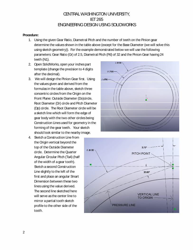
3. We will design the Pinion Gear first. Using the values given and derived from the formulas in the table above, sketch three concentric circles from the Origin on the Front Plane: Outside Diameter (Do)circle, Root Diameter (Dr) circle and Pitch Diameter (Dp) circle. The Root Diameter circle will be a sketch line which will form the edge of gear body with the two other circles being Construction Lines used for geometry in the forming of the gear teeth. Your sketch should look similar to the nearby image.
4. Sketch a Construction Line from the Origin vertical beyond the top of the Outside Diameter circle. Determine the Quarter Angular Circular Pitch (Ta4) (half of the width of a gear tooth). Sketch a second Construction Line slightly to the left of the first and place an angular Smart Dimension between these two lines using the value derived. The second line sketched here will serve as the center line to mirror a partial tooth sketch profile to the other side of the tooth.

CENTRAL WASHINGTON UNIVERSITY, IET 265
ENGINEERING DESIGN USING SOLIDWORKS
3
5. Sketch a horizontal Construction Line to the left from the intersection of both the Pitch Diameter circle and the vertical line sketched in the previous step. The point at this intersection is named the Pitch Point. Sketch a Construction Line from the Pitch Point 20° below the horizontal line. This is the Pressure Line and represents the line of pressure from the powered gear tooth to the non-powered tooth of the opposing gear and will be approximately perpendicular to the tooth surface at this point. In our gear assignment the more common 20° pressure angle will be used (Designs using other angles, such as 14.5° are less common). Your sketch should look similar to the image above.
6. Now sketch the Base Diameter (Db) circle as opposed to using a formula. This circle has its center at the Origin and is tangent to the Pressure line.
7. Sketch the first Pitch Point Diameter (Dpp) circle with the center at the Pitch Point. Sketch the second Pitch Point Circle with the center at the intersection of the first Pitch Point Circle and the Base Diameter. A portion of this circle will represent the upper arc or the involute portion of the gear tooth.
8. Now sketch a 3 Point Arc. This arc will represent the top or involute edge of one of the gear teeth. Place the first point of the arc at the intersection of the Outside Diameter circle and the second Pitch Point Diameter circle, the second point at the intersection of the Pitch Diameter circle and the second Pitch Point Diameter circle with the third point somewhere on the second Pitch Point Diameter circle. When placing the third point a tangent sketch Relation is added automatically by SolidWorks. If the last step does not work then snap the third point of the arc near the circle and establish a co-radial Sketch Relation between the arc and the second Pitch Point Diameter circle. Refer to the image nearby.

CENTRAL WASHINGTON UNIVERSITY, IET 265
ENGINEERING DESIGN USING SOLIDWORKS
4
9. Now sketch a Tangent Arc. This arc will represent the bottom edge of one of the gear teeth. Start this arc on the bottom end point of the 3 Point Arc, sketched in the step above, to the Root Diameter circle. This arc needs to be perpendicular to the Root Diameter circle. Refer to the image nearby.
10. To make the bottom arc perpendicular to the Root Diameter, sketch a Construction Line from the endpoint of the arc sketched above to the Origin. Make this line tangent to the arc sketched above. You may have to move the intersection of the Construction Line and arc to one side of the second Pitch Point Diameter circle or the other in order to get the tangency to work. This arc will not be co-radial to the second Pitch Point Diameter circle!
11. Now mirror the two arcs sketched in the steps above using the Construction Line representing Quarter Angular Circular Pitch as a mirror sketch entity. Sketch a 3 Point Arc connecting the two endpoints of the mirrored arcs on the top with the third point on the Outside Diameter circle. If the last step does not work then snap the third point of the arc near the circle and establish a co-radial Sketch Relation between the arc and the Outside Diameter circle. You should now have 2 areas of enclosed geometry, one for the gear tooth and the other the gear body. You are ready for some solid features.
CENTRAL WASHINGTON UNIVERSITY, IET 265
ENGINEERING DESIGN USING SOLIDWORKS
5
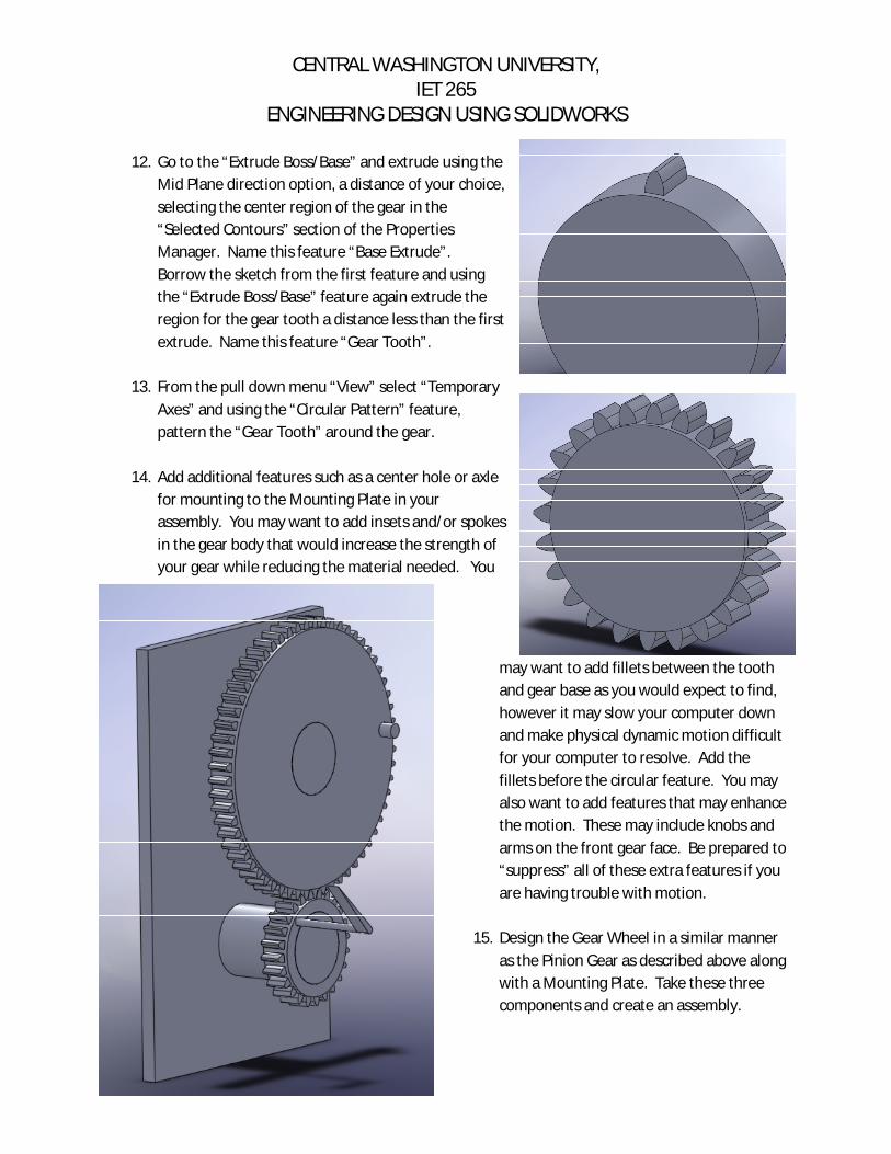
12. Go to the “Extrude Boss/Base” and extrude using the Mid Plane direction option, a distance of your choice, selecting the center region of the gear in the “Selected Contours” section of the Properties Manager. Name this feature “Base Extrude”. Borrow the sketch from the first feature and using the “Extrude Boss/Base” feature again extrude the region for the gear tooth a distance less than the first extrude. Name this feature “Gear Tooth”.
13. From the pull down menu “View” select “Temporary
Axes” and using the “Circular Pattern” feature, pattern the “Gear Tooth” around the gear.
14. Add additional features such as a center hole or axle
for mounting to the Mounting Plate in your assembly. You may want to add insets and/or spokes in the gear body that would increase the strength of your gear while reducing the material needed. You
may want to add fillets between the tooth and gear base as you would expect to find, however it may slow your computer down and make physical dynamic motion difficult for your computer to resolve. Add the fillets before the circular feature. You may also want to add features that may enhance the motion. These may include knobs and arms on the front gear face. Be prepared to “suppress” all of these extra features if you are having trouble with motion.
15. Design the Gear Wheel in a similar manner
as the Pinion Gear as described above along with a Mounting Plate. Take these three components and create an assembly.