Embed Size (px)
Citation preview
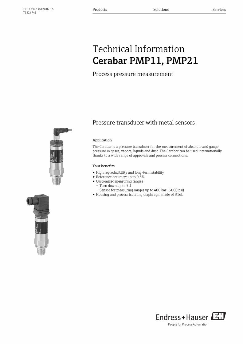
Pressure transducer with metal sensors
Application
The Cerabar is a pressure transducer for the measurement of absolute and gaugepressure in gases, vapors, liquids and dust. The Cerabar can be used internationallythanks to a wide range of approvals and process connections.
Your benefits
• High reproducibility and long-term stability• Reference accuracy: up to 0.3%• Customized measuring ranges
– Turn down up to 5:1– Sensor for measuring ranges up to 400 bar (6 000 psi)
• Housing and process isolating diaphragm made of 316L
Products Solutions Services
Technical InformationCerabar PMP11, PMP21Process pressure measurement
TI01133P/00/EN/02.1671326741
Cerabar PMP11, PMP21
2 Endress+Hauser
Table of contents
Document information . . . . . . . . . . . . . . . . . . . . . . . 4Document function . . . . . . . . . . . . . . . . . . . . . . . . . . . . 4Symbols used . . . . . . . . . . . . . . . . . . . . . . . . . . . . . . . . 4Documentation . . . . . . . . . . . . . . . . . . . . . . . . . . . . . . . 5Terms and abbreviations . . . . . . . . . . . . . . . . . . . . . . . . 6Turn down calculation . . . . . . . . . . . . . . . . . . . . . . . . . . 7
Function and system design . . . . . . . . . . . . . . . . . . . 8Measuring principle - process pressure measurement . . . . . 8Measuring system . . . . . . . . . . . . . . . . . . . . . . . . . . . . . 8Device features . . . . . . . . . . . . . . . . . . . . . . . . . . . . . . . 9Product design . . . . . . . . . . . . . . . . . . . . . . . . . . . . . . 10System integration . . . . . . . . . . . . . . . . . . . . . . . . . . . 10
Input . . . . . . . . . . . . . . . . . . . . . . . . . . . . . . . . . . . . 11Measured variable . . . . . . . . . . . . . . . . . . . . . . . . . . . . 11Measuring range . . . . . . . . . . . . . . . . . . . . . . . . . . . . 11
Output . . . . . . . . . . . . . . . . . . . . . . . . . . . . . . . . . . 13Output signal . . . . . . . . . . . . . . . . . . . . . . . . . . . . . . . 13Signal range 4 to 20 mA . . . . . . . . . . . . . . . . . . . . . . . . 13Load (for 4 to 20 mA devices ) . . . . . . . . . . . . . . . . . . . . 13Load resistance (for 0 to 10 V devices) . . . . . . . . . . . . . . 13Signal on alarm 4 to 20 mA . . . . . . . . . . . . . . . . . . . . . . 13Dead time, time constant . . . . . . . . . . . . . . . . . . . . . . . 14Dynamic behavior . . . . . . . . . . . . . . . . . . . . . . . . . . . . 14
Power supply . . . . . . . . . . . . . . . . . . . . . . . . . . . . . 15Terminal assignment . . . . . . . . . . . . . . . . . . . . . . . . . . 15Supply voltage . . . . . . . . . . . . . . . . . . . . . . . . . . . . . . 15Current consumption and alarm signal . . . . . . . . . . . . . . 15Power supply fault . . . . . . . . . . . . . . . . . . . . . . . . . . . . 16Electrical connection . . . . . . . . . . . . . . . . . . . . . . . . . . 16Cable specification . . . . . . . . . . . . . . . . . . . . . . . . . . . . 16Residual ripple . . . . . . . . . . . . . . . . . . . . . . . . . . . . . . 16Influence of power supply . . . . . . . . . . . . . . . . . . . . . . . 16Overvoltage protection . . . . . . . . . . . . . . . . . . . . . . . . 16
Performance characteristics of metallic processisolating diaphragm . . . . . . . . . . . . . . . . . . . . . . . . 17Reference operating conditions . . . . . . . . . . . . . . . . . . . 17Measuring uncertainty for small absolute pressuremeasuring ranges . . . . . . . . . . . . . . . . . . . . . . . . . . . . 17Influence of the installation position . . . . . . . . . . . . . . . . 17Resolution . . . . . . . . . . . . . . . . . . . . . . . . . . . . . . . . . 17Reference accuracy . . . . . . . . . . . . . . . . . . . . . . . . . . . 17Thermal change of the zero output and the output span . . . 17Long-term stability . . . . . . . . . . . . . . . . . . . . . . . . . . . 17Switch-on time . . . . . . . . . . . . . . . . . . . . . . . . . . . . . . 17
Installation . . . . . . . . . . . . . . . . . . . . . . . . . . . . . . . 18Installation conditions . . . . . . . . . . . . . . . . . . . . . . . . . 18Influence of the installation position . . . . . . . . . . . . . . . . 18Mounting location . . . . . . . . . . . . . . . . . . . . . . . . . . . . 18
Environment . . . . . . . . . . . . . . . . . . . . . . . . . . . . . . 20Ambient temperature range . . . . . . . . . . . . . . . . . . . . . 20Storage temperature range . . . . . . . . . . . . . . . . . . . . . . 20Climate class . . . . . . . . . . . . . . . . . . . . . . . . . . . . . . . 20Degree of protection . . . . . . . . . . . . . . . . . . . . . . . . . . 20Vibration resistance . . . . . . . . . . . . . . . . . . . . . . . . . . . 20Electromagnetic compatibility . . . . . . . . . . . . . . . . . . . . 20
Process . . . . . . . . . . . . . . . . . . . . . . . . . . . . . . . . . . 21Process temperature range for devices with metallicprocess isolating diaphragm . . . . . . . . . . . . . . . . . . . . . 21Pressure specifications . . . . . . . . . . . . . . . . . . . . . . . . . 21
Mechanical construction . . . . . . . . . . . . . . . . . . . . 22Design, dimensions . . . . . . . . . . . . . . . . . . . . . . . . . . . 22Electrical connection . . . . . . . . . . . . . . . . . . . . . . . . . . 22Housing . . . . . . . . . . . . . . . . . . . . . . . . . . . . . . . . . . . 23Process connections with internal, metal process isolatingdiaphragm . . . . . . . . . . . . . . . . . . . . . . . . . . . . . . . . . 24Process connections with internal, metal process isolatingdiaphragm . . . . . . . . . . . . . . . . . . . . . . . . . . . . . . . . . 25Process connections with internal, metal process isolatingdiaphragm . . . . . . . . . . . . . . . . . . . . . . . . . . . . . . . . . 26Process connections with flush-mounted, metal processisolating diaphragm . . . . . . . . . . . . . . . . . . . . . . . . . . . 27Process connections with flush-mounted, metal processisolating diaphragm . . . . . . . . . . . . . . . . . . . . . . . . . . . 27Materials in contact with process . . . . . . . . . . . . . . . . . . 28Materials not in contact with process . . . . . . . . . . . . . . . 29Cleaning . . . . . . . . . . . . . . . . . . . . . . . . . . . . . . . . . . 29
Operability . . . . . . . . . . . . . . . . . . . . . . . . . . . . . . . 30Plug-on display PHX20 (optional) . . . . . . . . . . . . . . . . . . 30
Certificates and approvals . . . . . . . . . . . . . . . . . . . 31CE mark . . . . . . . . . . . . . . . . . . . . . . . . . . . . . . . . . . . 31RCM-Tick marking . . . . . . . . . . . . . . . . . . . . . . . . . . . . 31Approval . . . . . . . . . . . . . . . . . . . . . . . . . . . . . . . . . . 31Safety Instructions (XA) . . . . . . . . . . . . . . . . . . . . . . . . 31Marine approval (pending) . . . . . . . . . . . . . . . . . . . . . . 31Pressure Equipment Directive (PED) . . . . . . . . . . . . . . . . 31Other standards and guidelines . . . . . . . . . . . . . . . . . . . 31CRN approval . . . . . . . . . . . . . . . . . . . . . . . . . . . . . . . 32Calibration unit . . . . . . . . . . . . . . . . . . . . . . . . . . . . . . 32Calibration . . . . . . . . . . . . . . . . . . . . . . . . . . . . . . . . . 32Inspection certificates . . . . . . . . . . . . . . . . . . . . . . . . . . 32
Ordering information . . . . . . . . . . . . . . . . . . . . . . . 33Scope of delivery . . . . . . . . . . . . . . . . . . . . . . . . . . . . . 33
Accessories . . . . . . . . . . . . . . . . . . . . . . . . . . . . . . . 34Weld-in adapter . . . . . . . . . . . . . . . . . . . . . . . . . . . . . 34Plug-on display PHX20 . . . . . . . . . . . . . . . . . . . . . . . . . 34M12 plug connectors . . . . . . . . . . . . . . . . . . . . . . . . . . 34
Documentation . . . . . . . . . . . . . . . . . . . . . . . . . . . . 35Field of Activities . . . . . . . . . . . . . . . . . . . . . . . . . . . . 35
Cerabar PMP11, PMP21
Endress+Hauser 3
Technical Information . . . . . . . . . . . . . . . . . . . . . . . . . 35Operating Instructions . . . . . . . . . . . . . . . . . . . . . . . . . 35Brief Operating Instructions . . . . . . . . . . . . . . . . . . . . . 35Safety Instructions (XA) . . . . . . . . . . . . . . . . . . . . . . . . 35
Cerabar PMP11, PMP21
4 Endress+Hauser
Document information
Document function The document contains all the technical data on the device and provides an overview of theaccessories and other products that can be ordered for the device.
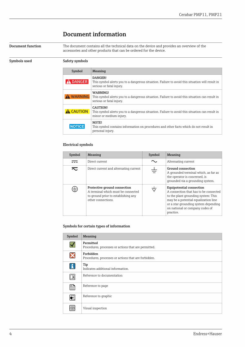
Symbols used Safety symbols
Symbol Meaning
DANGER
DANGER!This symbol alerts you to a dangerous situation. Failure to avoid this situation will result inserious or fatal injury.
WARNING
WARNING!This symbol alerts you to a dangerous situation. Failure to avoid this situation can result inserious or fatal injury.
CAUTION
CAUTION!This symbol alerts you to a dangerous situation. Failure to avoid this situation can result inminor or medium injury.
NOTICE
NOTE!This symbol contains information on procedures and other facts which do not result inpersonal injury.
Electrical symbols
Symbol Meaning Symbol Meaning
Direct current Alternating current
Direct current and alternating current Ground connectionA grounded terminal which, as far asthe operator is concerned, isgrounded via a grounding system.
Protective ground connectionA terminal which must be connectedto ground prior to establishing anyother connections.
Equipotential connectionA connection that has to be connectedto the plant grounding system: Thismay be a potential equalization lineor a star grounding system dependingon national or company codes ofpractice.
Symbols for certain types of information
Symbol Meaning
PermittedProcedures, processes or actions that are permitted.
ForbiddenProcedures, processes or actions that are forbidden.
TipIndicates additional information.
Reference to documentation
Reference to page
Reference to graphic
Visual inspection
Cerabar PMP11, PMP21
Endress+Hauser 5
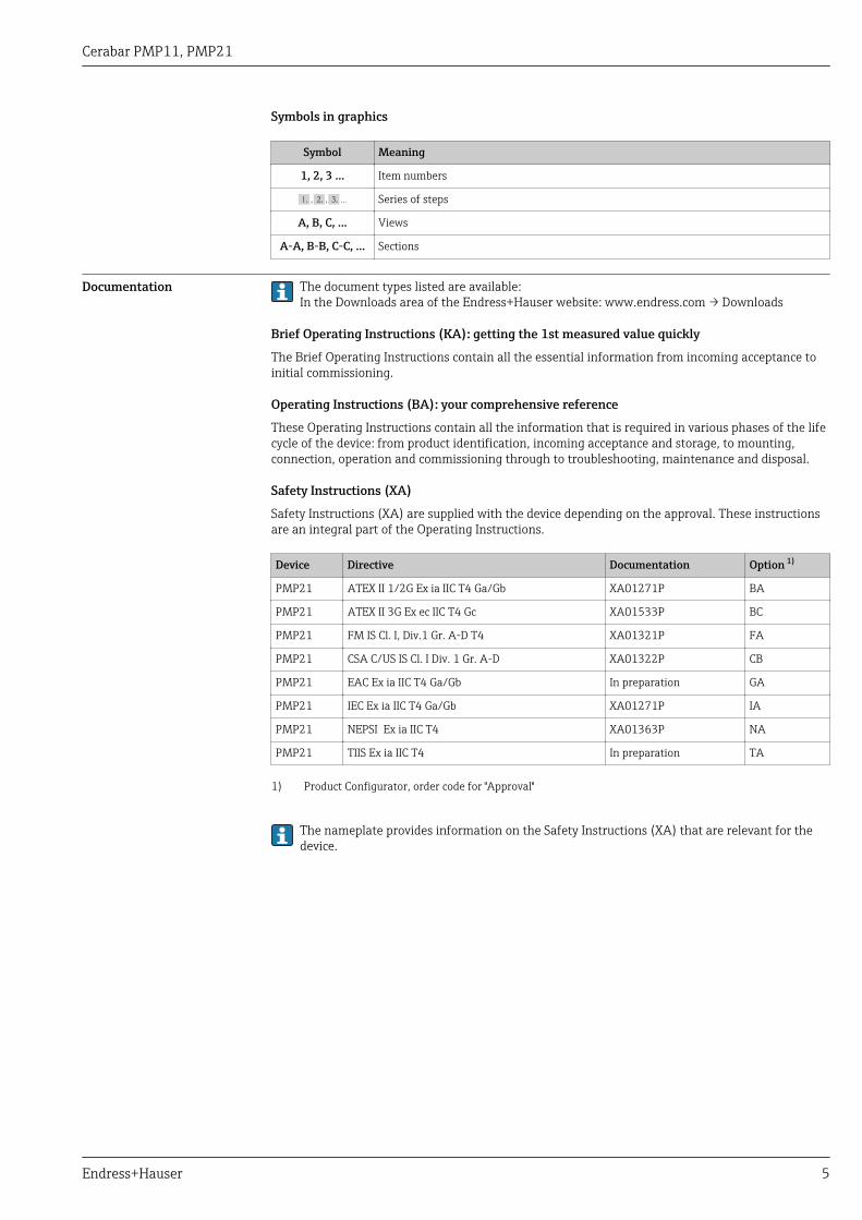
Symbols in graphics
Symbol Meaning
1, 2, 3 ... Item numbers
, …, Series of steps
A, B, C, ... Views
A-A, B-B, C-C, ... Sections
Documentation The document types listed are available:In the Downloads area of the Endress+Hauser website: www.endress.com → Downloads
Brief Operating Instructions (KA): getting the 1st measured value quickly
The Brief Operating Instructions contain all the essential information from incoming acceptance toinitial commissioning.
Operating Instructions (BA): your comprehensive reference
These Operating Instructions contain all the information that is required in various phases of the lifecycle of the device: from product identification, incoming acceptance and storage, to mounting,connection, operation and commissioning through to troubleshooting, maintenance and disposal.
Safety Instructions (XA)
Safety Instructions (XA) are supplied with the device depending on the approval. These instructionsare an integral part of the Operating Instructions.
Device Directive Documentation Option 1)
PMP21 ATEX II 1/2G Ex ia IIC T4 Ga/Gb XA01271P BA
PMP21 ATEX II 3G Ex ec IIC T4 Gc XA01533P BC
PMP21 FM IS Cl. I, Div.1 Gr. A-D T4 XA01321P FA
PMP21 CSA C/US IS Cl. I Div. 1 Gr. A-D XA01322P CB
PMP21 EAC Ex ia IIC T4 Ga/Gb In preparation GA
PMP21 IEC Ex ia IIC T4 Ga/Gb XA01271P IA
PMP21 NEPSI Ex ia IIC T4 XA01363P NA
PMP21 TIIS Ex ia IIC T4 In preparation TA
1) Product Configurator, order code for "Approval"
The nameplate provides information on the Safety Instructions (XA) that are relevant for thedevice.
Cerabar PMP11, PMP21
6 Endress+Hauser
Terms and abbreviations
URL OPLMWPLRL
0
p
LRV URV
1
2
3
4
A0029505
Item Term/abbreviation
Explanation
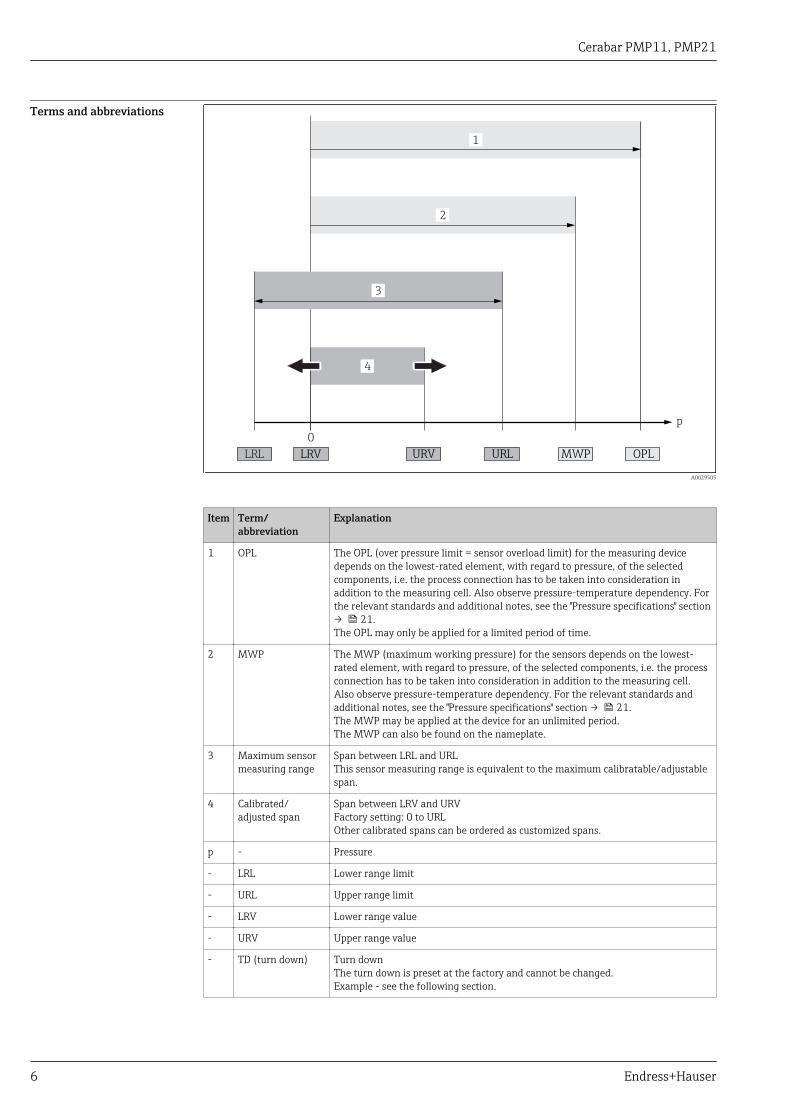
1 OPL The OPL (over pressure limit = sensor overload limit) for the measuring devicedepends on the lowest-rated element, with regard to pressure, of the selectedcomponents, i.e. the process connection has to be taken into consideration inaddition to the measuring cell. Also observe pressure-temperature dependency. Forthe relevant standards and additional notes, see the "Pressure specifications" section→ 21.The OPL may only be applied for a limited period of time.
2 MWP The MWP (maximum working pressure) for the sensors depends on the lowest-rated element, with regard to pressure, of the selected components, i.e. the processconnection has to be taken into consideration in addition to the measuring cell.Also observe pressure-temperature dependency. For the relevant standards andadditional notes, see the "Pressure specifications" section → 21.The MWP may be applied at the device for an unlimited period.The MWP can also be found on the nameplate.
3 Maximum sensormeasuring range
Span between LRL and URLThis sensor measuring range is equivalent to the maximum calibratable/adjustablespan.
4 Calibrated/adjusted span
Span between LRV and URVFactory setting: 0 to URLOther calibrated spans can be ordered as customized spans.
p - Pressure
- LRL Lower range limit
- URL Upper range limit
- LRV Lower range value
- URV Upper range value
- TD (turn down) Turn downThe turn down is preset at the factory and cannot be changed.Example - see the following section.
Cerabar PMP11, PMP21
Endress+Hauser 7
Turn down calculation
LRV URLURVLRL
1 = 2 3
A0029545
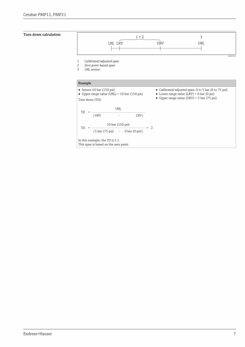
1 Calibrated/adjusted span2 Zero point-based span3 URL sensor
Example
• Sensor:10 bar (150 psi)• Upper range value (URL) = 10 bar (150 psi)
Turn down (TD):
• Calibrated/adjusted span: 0 to 5 bar (0 to 75 psi)• Lower range value (LRV) = 0 bar (0 psi)• Upper range value (URV) = 5 bar (75 psi)
TD =URL
|URV - LRV|
TD =10 bar (150 psi)
= 2|5 bar (75 psi) - 0 bar (0 psi)|
In this example, the TD is 2:1.This span is based on the zero point.
Cerabar PMP11, PMP21
8 Endress+Hauser
Function and system design
Measuring principle -process pressuremeasurement
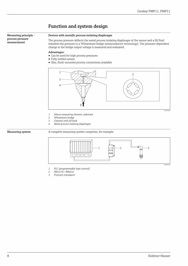
Devices with metallic process isolating diaphragm
The process pressure deflects the metal process isolating diaphragm of the sensor and a fill fluidtransfers the pressure to a Wheatstone bridge (semiconductor technology). The pressure-dependentchange in the bridge output voltage is measured and evaluated.
Advantages:• Can be used for high process pressures• Fully welded sensor• Slim, flush-mounted process connections available
p
1
3
4
2
A0016448
1 Silicon measuring element, substrate2 Wheatstone bridge3 Channel with fill fluid4 Metal process isolating diaphragm
Measuring system A complete measuring system comprises, for example:
1 2 3
A0021926
1 PLC (programmable logic control)2 RN221N / RMA423 Pressure transducer
Cerabar PMP11, PMP21
Endress+Hauser 9
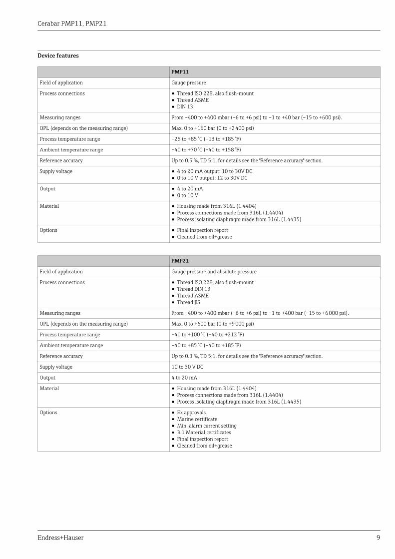
Device features
PMP11
Field of application Gauge pressure
Process connections • Thread ISO 228, also flush-mount• Thread ASME• DIN 13
Measuring ranges From –400 to +400 mbar (–6 to +6 psi) to –1 to +40 bar (–15 to +600 psi).
OPL (depends on the measuring range) Max. 0 to +160 bar (0 to +2 400 psi)
Process temperature range –25 to +85 °C (–13 to +185 °F)
Ambient temperature range –40 to +70 °C (–40 to +158 °F)
Reference accuracy Up to 0.5 %, TD 5:1, for details see the "Reference accuracy" section.
Supply voltage • 4 to 20 mA output: 10 to 30V DC• 0 to 10 V output: 12 to 30V DC
Output • 4 to 20 mA• 0 to 10 V
Material • Housing made from 316L (1.4404)• Process connections made from 316L (1.4404)• Process isolating diaphragm made from 316L (1.4435)
Options • Final inspection report• Cleaned from oil+grease
PMP21
Field of application Gauge pressure and absolute pressure
Process connections • Thread ISO 228, also flush-mount• Thread DIN 13• Thread ASME• Thread JIS
Measuring ranges From –400 to +400 mbar (–6 to +6 psi) to –1 to +400 bar (–15 to +6 000 psi).
OPL (depends on the measuring range) Max. 0 to +600 bar (0 to +9 000 psi)
Process temperature range –40 to +100 °C (–40 to +212 °F)
Ambient temperature range –40 to +85 °C (–40 to +185 °F)
Reference accuracy Up to 0.3 %, TD 5:1, for details see the "Reference accuracy" section.
Supply voltage 10 to 30 V DC
Output 4 to 20 mA
Material • Housing made from 316L (1.4404)• Process connections made from 316L (1.4404)• Process isolating diaphragm made from 316L (1.4435)
Options • Ex approvals• Marine certificate• Min. alarm current setting• 3.1 Material certificates• Final inspection report• Cleaned from oil+grease
Cerabar PMP11, PMP21
10 Endress+Hauser
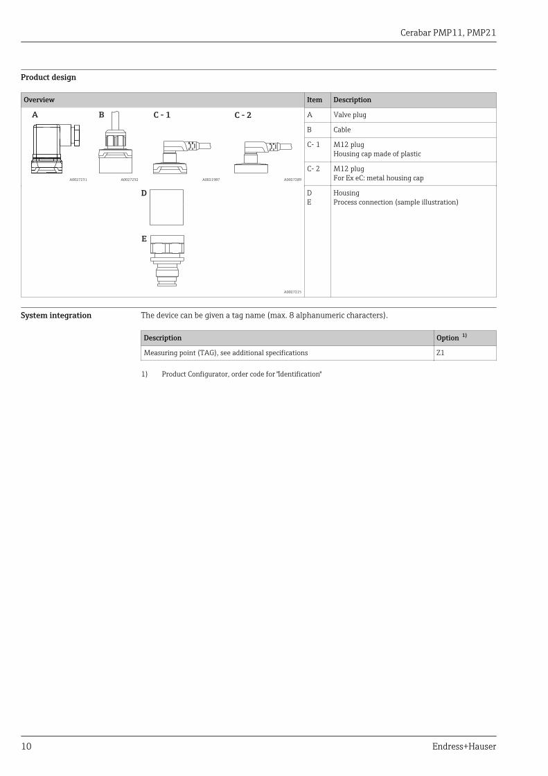
Product design
Overview Item Description
A
A0027231
B
A0027232
C - 1
A0021987
C - 2
A0027289
A Valve plug
B Cable
C- 1 M12 plugHousing cap made of plastic
C- 2 M12 plugFor Ex eC: metal housing cap
D
E
A0027215
DE
HousingProcess connection (sample illustration)
System integration The device can be given a tag name (max. 8 alphanumeric characters).
Description Option 1)
Measuring point (TAG), see additional specifications Z1
1) Product Configurator, order code for "Identification"
Cerabar PMP11, PMP21
Endress+Hauser 11
Input
Measured variable Measured process variable
• PMP11: gauge pressure• PMP21: gauge pressure or absolute pressure
Calculated process variable
Pressure
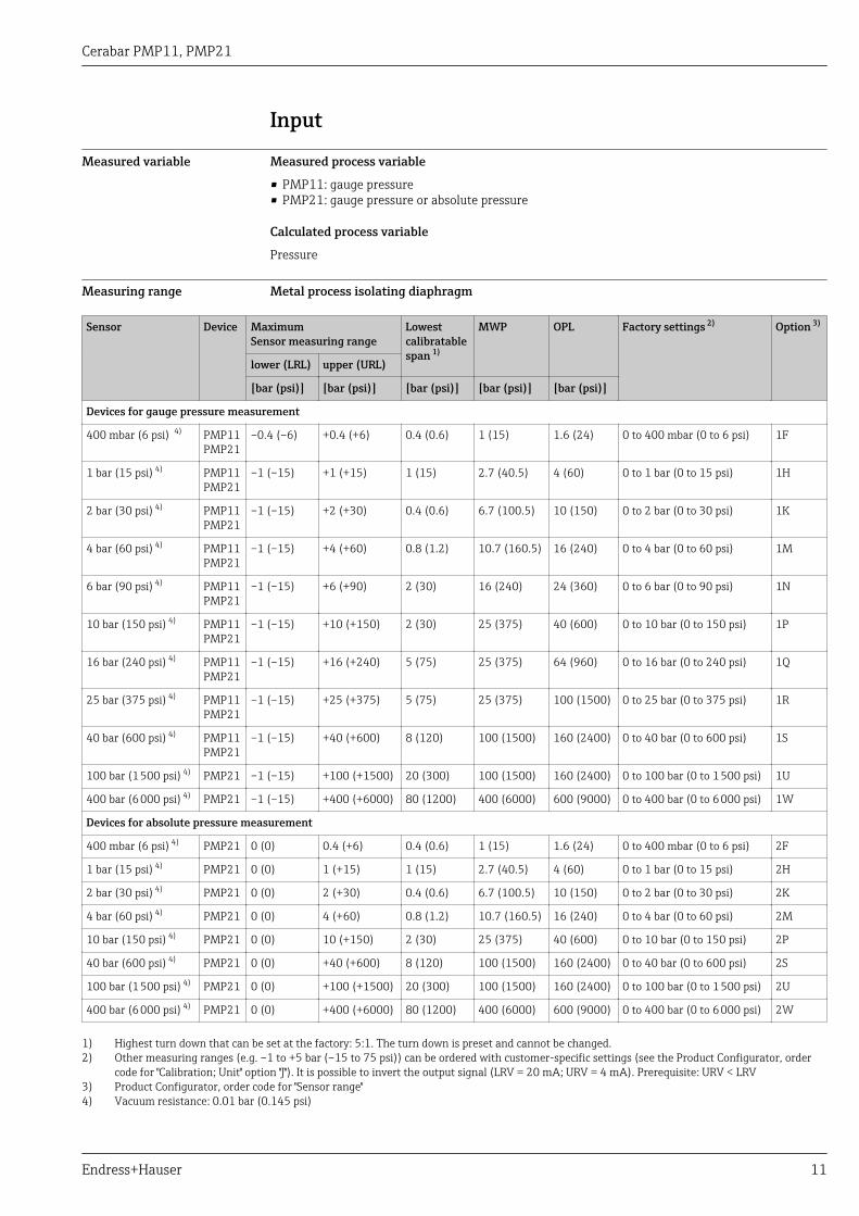
Measuring range Metal process isolating diaphragm
Sensor Device MaximumSensor measuring range
Lowestcalibratablespan 1)
MWP OPL Factory settings 2) Option 3)
lower (LRL) upper (URL)
[bar (psi)] [bar (psi)] [bar (psi)] [bar (psi)] [bar (psi)]
Devices for gauge pressure measurement
400 mbar (6 psi) 4) PMP11PMP21
–0.4 (–6) +0.4 (+6) 0.4 (0.6) 1 (15) 1.6 (24) 0 to 400 mbar (0 to 6 psi) 1F
1 bar (15 psi) 4) PMP11PMP21
–1 (–15) +1 (+15) 1 (15) 2.7 (40.5) 4 (60) 0 to 1 bar (0 to 15 psi) 1H
2 bar (30 psi) 4) PMP11PMP21
–1 (–15) +2 (+30) 0.4 (0.6) 6.7 (100.5) 10 (150) 0 to 2 bar (0 to 30 psi) 1K
4 bar (60 psi) 4) PMP11PMP21
–1 (–15) +4 (+60) 0.8 (1.2) 10.7 (160.5) 16 (240) 0 to 4 bar (0 to 60 psi) 1M
6 bar (90 psi) 4) PMP11PMP21
–1 (–15) +6 (+90) 2 (30) 16 (240) 24 (360) 0 to 6 bar (0 to 90 psi) 1N
10 bar (150 psi) 4) PMP11PMP21
–1 (–15) +10 (+150) 2 (30) 25 (375) 40 (600) 0 to 10 bar (0 to 150 psi) 1P
16 bar (240 psi) 4) PMP11PMP21
–1 (–15) +16 (+240) 5 (75) 25 (375) 64 (960) 0 to 16 bar (0 to 240 psi) 1Q
25 bar (375 psi) 4) PMP11PMP21
–1 (–15) +25 (+375) 5 (75) 25 (375) 100 (1500) 0 to 25 bar (0 to 375 psi) 1R
40 bar (600 psi) 4) PMP11PMP21
–1 (–15) +40 (+600) 8 (120) 100 (1500) 160 (2400) 0 to 40 bar (0 to 600 psi) 1S
100 bar (1 500 psi) 4) PMP21 –1 (–15) +100 (+1500) 20 (300) 100 (1500) 160 (2400) 0 to 100 bar (0 to 1 500 psi) 1U
400 bar (6 000 psi) 4) PMP21 –1 (–15) +400 (+6000) 80 (1200) 400 (6000) 600 (9000) 0 to 400 bar (0 to 6 000 psi) 1W
Devices for absolute pressure measurement
400 mbar (6 psi) 4) PMP21 0 (0) 0.4 (+6) 0.4 (0.6) 1 (15) 1.6 (24) 0 to 400 mbar (0 to 6 psi) 2F
1 bar (15 psi) 4) PMP21 0 (0) 1 (+15) 1 (15) 2.7 (40.5) 4 (60) 0 to 1 bar (0 to 15 psi) 2H
2 bar (30 psi) 4) PMP21 0 (0) 2 (+30) 0.4 (0.6) 6.7 (100.5) 10 (150) 0 to 2 bar (0 to 30 psi) 2K
4 bar (60 psi) 4) PMP21 0 (0) 4 (+60) 0.8 (1.2) 10.7 (160.5) 16 (240) 0 to 4 bar (0 to 60 psi) 2M
10 bar (150 psi) 4) PMP21 0 (0) 10 (+150) 2 (30) 25 (375) 40 (600) 0 to 10 bar (0 to 150 psi) 2P
40 bar (600 psi) 4) PMP21 0 (0) +40 (+600) 8 (120) 100 (1500) 160 (2400) 0 to 40 bar (0 to 600 psi) 2S
100 bar (1 500 psi) 4) PMP21 0 (0) +100 (+1500) 20 (300) 100 (1500) 160 (2400) 0 to 100 bar (0 to 1 500 psi) 2U
400 bar (6 000 psi) 4) PMP21 0 (0) +400 (+6000) 80 (1200) 400 (6000) 600 (9000) 0 to 400 bar (0 to 6 000 psi) 2W
1) Highest turn down that can be set at the factory: 5:1. The turn down is preset and cannot be changed.2) Other measuring ranges (e.g. –1 to +5 bar (–15 to 75 psi)) can be ordered with customer-specific settings (see the Product Configurator, order
code for "Calibration; Unit" option "J"). It is possible to invert the output signal (LRV = 20 mA; URV = 4 mA). Prerequisite: URV < LRV3) Product Configurator, order code for "Sensor range"4) Vacuum resistance: 0.01 bar (0.145 psi)
Cerabar PMP11, PMP21
12 Endress+Hauser
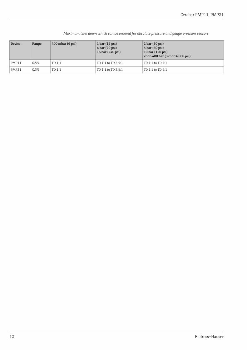
Maximum turn down which can be ordered for absolute pressure and gauge pressure sensors
Device Range 400 mbar (6 psi) 1 bar (15 psi)6 bar (90 psi)16 bar (240 psi)
2 bar (30 psi)4 bar (60 psi)10 bar (150 psi)25 to 400 bar (375 to 6 000 psi)
PMP11 0.5% TD 1:1 TD 1:1 to TD 2.5:1 TD 1:1 to TD 5:1
PMP21 0.3% TD 1:1 TD 1:1 to TD 2.5:1 TD 1:1 to TD 5:1
Cerabar PMP11, PMP21
Endress+Hauser 13
Output
Output signal Description Option 1)
4 to 20 mA (2-wire) 1
PMP11: 0 to 10 V output (3-wire) 2
1) Product Configurator, order code for "Output"
Signal range 4 to 20 mA 3.8 mA to 20.5 mA
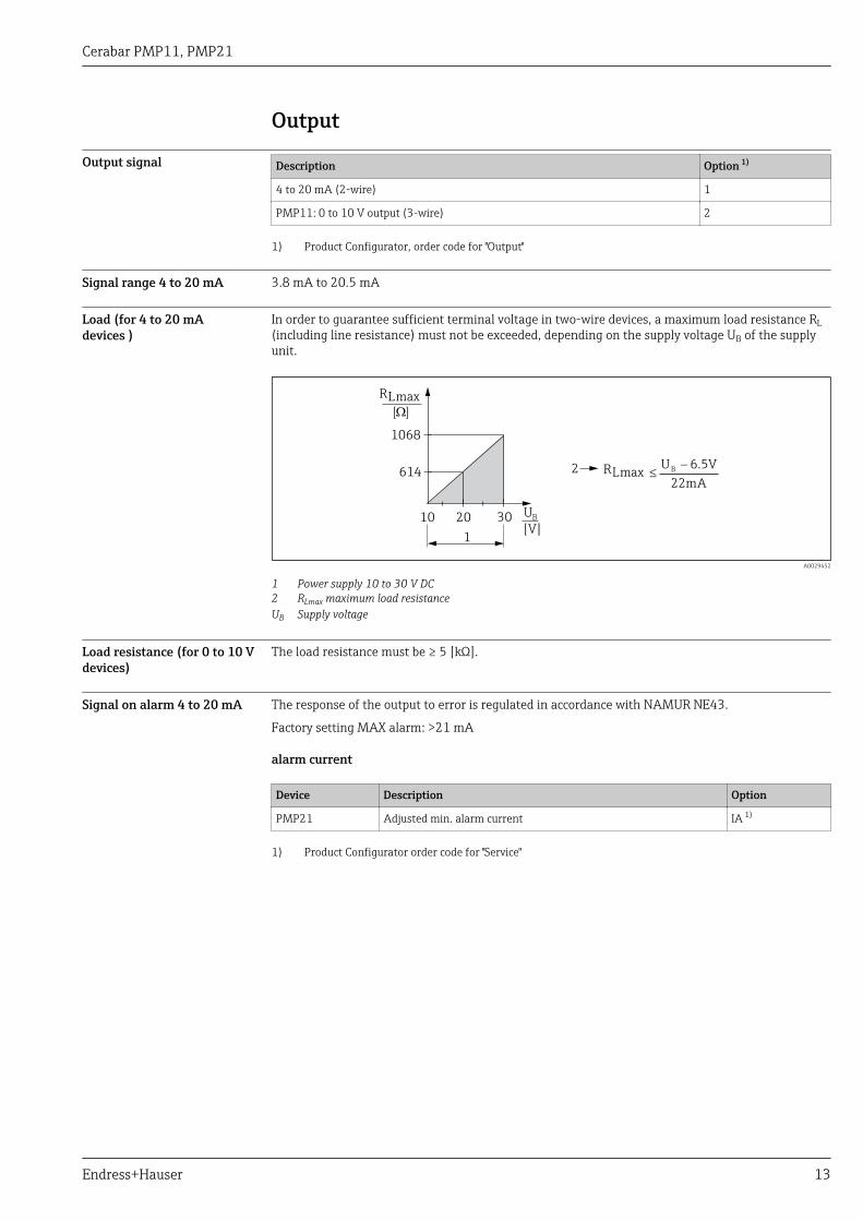
Load (for 4 to 20 mAdevices )
In order to guarantee sufficient terminal voltage in two-wire devices, a maximum load resistance RL(including line resistance) must not be exceeded, depending on the supply voltage UB of the supplyunit.
[ ]W
302010
1068
614
U
[V]1
2
R
R
L
L
max
max £-U 6.5V
22mA
B
B
A0029452
1 Power supply 10 to 30 V DC2 RLmax maximum load resistanceUB Supply voltage
Load resistance (for 0 to 10 Vdevices)
The load resistance must be ≥ 5 [kΩ].
Signal on alarm 4 to 20 mA The response of the output to error is regulated in accordance with NAMUR NE43.
Factory setting MAX alarm: >21 mA
alarm current
Device Description Option
PMP21 Adjusted min. alarm current IA 1)
1) Product Configurator order code for "Service"
Cerabar PMP11, PMP21
14 Endress+Hauser
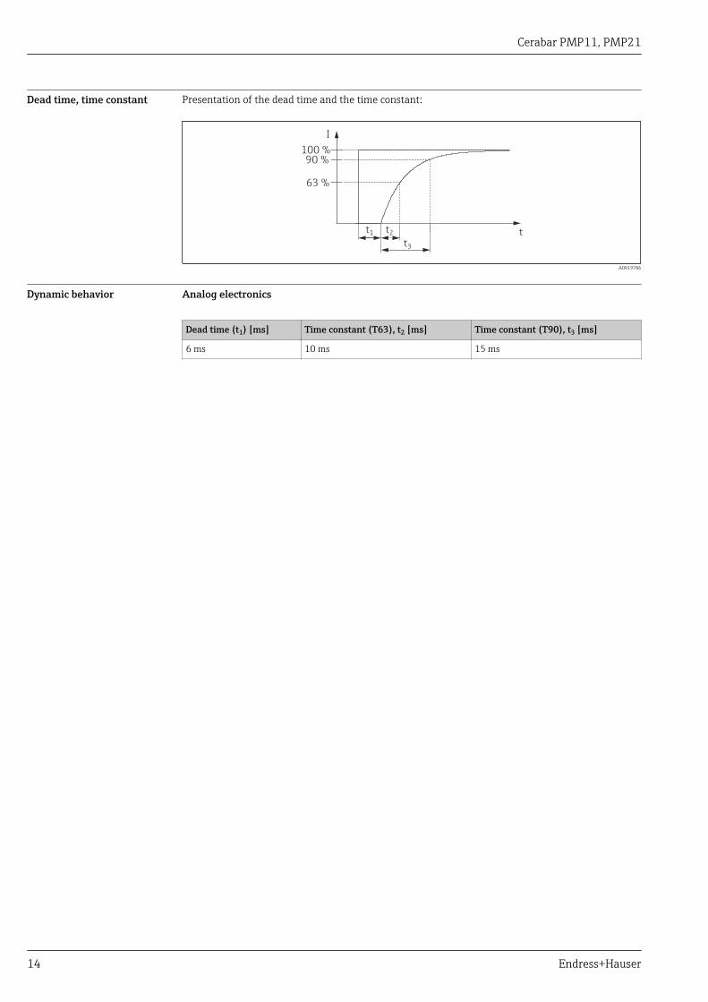
Dead time, time constant Presentation of the dead time and the time constant:
I
63 %
100 %
tt1 t2
90 %
t3
A0019786
Dynamic behavior Analog electronics
Dead time (t1) [ms] Time constant (T63), t2 [ms] Time constant (T90), t3 [ms]
6 ms 10 ms 15 ms
Cerabar PMP11, PMP21
Endress+Hauser 15
Power supplyLWARNING
Limitation of electrical safety due to incorrect connection!‣ In accordance with IEC/EN61010 a separate circuit breaker must be provided for the device .‣ When using the measuring device in hazardous areas, installation must comply with the
corresponding national standards and regulations and the Safety Instructions or Installation orControl Drawings.
‣ All explosion protection data are given in separate documentation which is available uponrequest. The Ex documentation is supplied as standard with all devices approved for use inexplosion hazardous areas.
‣ Protective circuits against reverse polarity, HF influences and overvoltage peaks are integrated.‣ The device must be operated with a 500 mA fine-wire fuse (slow-blow).
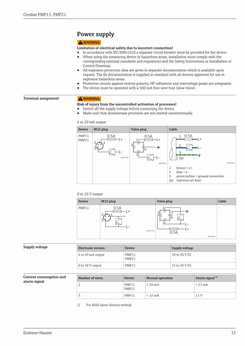
Terminal assignment LWARNINGRisk of injury from the uncontrolled activation of processes!‣ Switch off the supply voltage before connecting the device.‣ Make sure that downstream processes are not started unintentionally.
4 to 20 mA output
Device M12 plug Valve plug Cable
PMP11PMP21
L–
L+2 1
3
0.5A
A0023487 L–
L+1
2
3
4
0.5A
A0022823
L–
L+1
2
3
(a)
0.5A
A0023783
1 brown = L+2 blue = L-3 green/yellow = ground connection(a) reference air hose
0 to 10 V output
Device M12 plug Valve plug Cable
PMP11
L–
L+2 1
3
0.5A
A0017576
L–
L+
1
2
3
4
0.5A
A0022822
-
Supply voltage Electronic version Device Supply voltage
4 to 20 mA output PMP11PMP21
10 to 30 V DC
0 to 10 V output PMP11 12 to 30 V DC
Current consumption andalarm signal
Number of wires Device Normal operation Alarm signal 1)
2 PMP11PMP21
≤ 26 mA > 21 mA
3 PMP11 < 12 mA 11 V
1) For MAX alarm (factory setting)
Cerabar PMP11, PMP21
16 Endress+Hauser
Power supply fault • Behavior in the event of overvoltage (>30 V):The device works continuously up to 34 V DC without damage. If the supply voltage is exceeded,the specified characteristics are no longer guaranteed.
• Behavior in the event of undervoltage:If the supply voltage falls below the minimum value, the device switches off in a defined manner(status same as for no power supply).
Electrical connection Degree of protection
Device Connection Climate class Option 1)
PMP21 Cable 5 m (16 ft) IP66/68 2) NEMA Type 4X/6P Enclosure A
PMP21 Cable 10 m (33 ft) IP66/68 2) NEMA Type 4X/6P Enclosure B
PMP21 Cable 25 m (82 ft) IP66/68 2) NEMA Type 4X/6P Enclosure C
PMP11 M12 plug made of plastic IP65 NEMA type 4X enclosure L
PMP21 M12 plug made of plastic IP65/67 NEMA type 4X enclosure M
PMP11PMP21
Valve plug ISO4400 M16 IP65 NEMA type 4X enclosure U
PMP11PMP21
Valve plug ISO4400 NPT ½ IP65 NEMA type 4X enclosure V
1) Product Configurator, order code for "Electrical connection"2) IP 68 (1.83 mH2O for 24 h)
Cable specification For valve plug: < 1.5 mm2 (16 AWG) and Ø3.5 to 6.5 mm (0.14 to 0.26 in)
Residual ripple The device operates within the reference accuracy up to ±5 % of the residual ripple of the supplyvoltage, within the permitted voltage range.
Influence of power supply ≤0.005 % of URL/1 V
Overvoltage protection The device does not contain any special elements to protect against overvoltage ("wire to ground").Nevertheless the requirements of the applicable EMC standard EN 61000-4-5 (testing voltage 1kVEMC wire/ground) are met.
Cerabar PMP11, PMP21
Endress+Hauser 17
Performance characteristics of metallic process isolatingdiaphragm
Reference operatingconditions
• As per IEC 60770• Ambient temperature TA = constant, in the range of:+21 to +33 °C (+70 to +91 °F)• Humidityj= constant, in range: 5 to 80 % rH• Ambient pressure pA = constant, in the range of:860 to 1 060 mbar (12.47 to 15.37 psi)• Position of measuring cell = constant, in range: horizontal ±1° (see also "Influence of the
installation position" section → 18)• Zero based span• Process isolating diaphragm material: AISI 316L (1.4435)• Filling oil: NSF-H1 synthetic oil in accordance with FDA 21 CFR 178.3570• Supply voltage: 24 V DC ±3 V DC• Load: 320 Ω
Measuring uncertainty forsmall absolute pressuremeasuring ranges
The smallest extended uncertainty of measurement that can delivered by our standards is:• in range 1 to 30 mbar (0.0145 to 0.435 psi): 0.4 % of reading• in range < 1 mbar (0.0145 psi): 1 % of reading.
Influence of the installationposition
→ 18
Resolution Current output: min. 1.6 μA
Reference accuracy The reference accuracy contains the non-linearity [DIN EN 61298-2 3.11] including the pressurehysteresis [DIN EN 61298-23.13] and non-repeatability [DIN EN 61298-2 3.11] in accordance withthe limit point method as per [DIN EN 60770].
Device TD 1) % of calibrated span Typical non-linearity Typical non-repeatability
PMP11 TD 1:1 to TD 5:1 ±0.5 ±0.1 ±0.1
PMP21 TD 1:1 to TD 5:1 ±0.3 ±0.1 ±0.1
1) Overview of the turn down ranges → 12
Thermal change of the zerooutput and the output span
Measuring cell –20 to +85 °C (–4 to +185 °F) –20 to –40 °C (–4 to –40 °F)+85 to +100 °C (+185 to +212 °F)
% of the calibrated span for TD 1:1
<1 bar (15 psi) <1 <1.2
≥ 1 bar (15 psi) <0.8 <1
Long-term stability Measuring ranges 1 year 5 years 10 year
% of URL
400 mbar (6 psi)to400 bar (6 000 psi)
±0.2 ±0.4 In preparation
Switch-on time ≤2 s
Cerabar PMP11, PMP21
18 Endress+Hauser
Installation
Installation conditions • No moisture may enter the housing when installing or operating the device, or when establishingthe electrical connection.
• Point the cable and connector downwards where possible to prevent moisture from entering (e.g.rain or condensation water).
Influence of the installationposition
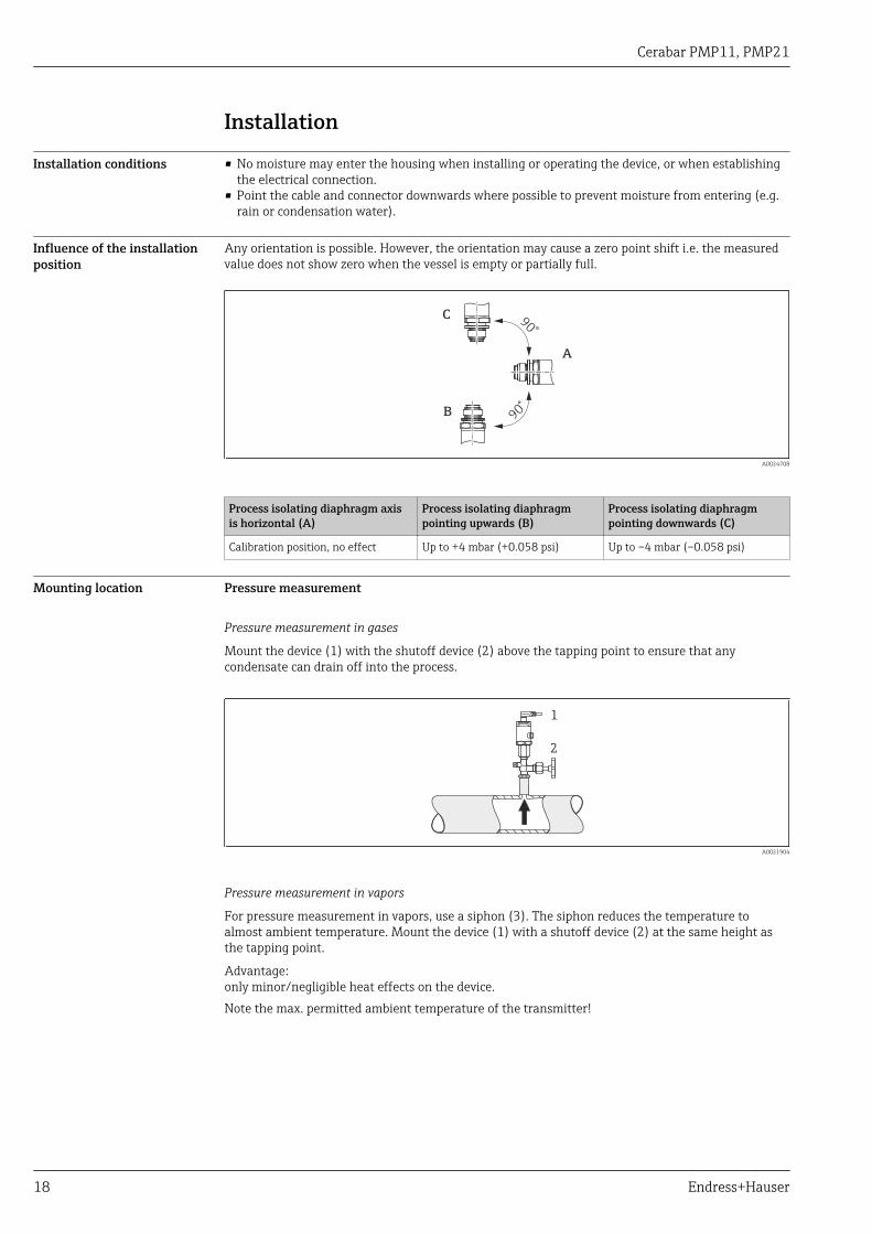
Any orientation is possible. However, the orientation may cause a zero point shift i.e. the measuredvalue does not show zero when the vessel is empty or partially full.
90°
90°
C
A
B
A0024708
Process isolating diaphragm axisis horizontal (A)
Process isolating diaphragmpointing upwards (B)
Process isolating diaphragmpointing downwards (C)
Calibration position, no effect Up to +4 mbar (+0.058 psi) Up to –4 mbar (–0.058 psi)
Mounting location Pressure measurement
Pressure measurement in gases
Mount the device (1) with the shutoff device (2) above the tapping point to ensure that anycondensate can drain off into the process.
1
2
A0021904
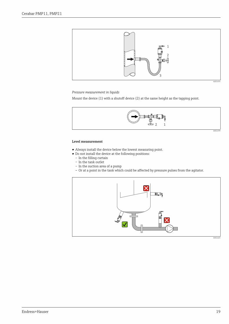
Pressure measurement in vapors
For pressure measurement in vapors, use a siphon (3). The siphon reduces the temperature toalmost ambient temperature. Mount the device (1) with a shutoff device (2) at the same height asthe tapping point.
Advantage:only minor/negligible heat effects on the device.Note the max. permitted ambient temperature of the transmitter!
Cerabar PMP11, PMP21
Endress+Hauser 19
1
2
3
A0024395
Pressure measurement in liquids
Mount the device (1) with a shutoff device (2) at the same height as the tapping point.
12
A0024399
Level measurement
• Always install the device below the lowest measuring point.• Do not install the device at the following positions:
– In the filling curtain– In the tank outlet– In the suction area of a pump– Or at a point in the tank which could be affected by pressure pulses from the agitator.
A0024405
Cerabar PMP11, PMP21
20 Endress+Hauser
Environment
Ambient temperature range Device Ambient temperature range 1)
PMP11 –40 to +70 °C (–40 to +158 °F)
PMP21 –40 to +85 °C (–40 to +185 °F)
PMP21 Devices for hazardous areas: –40 to +70 °C (–40 to +158 °F)
1) Exception: the following cable is designed for an operating temperature range of–25 to +70 °C (–13 to +158 °F): Product Configurator order code for "Accessory enclosed", option "RZ".
Storage temperature range –40 to +85 °C (–40 to +185 °F)
Climate class Device Climate class Note
PMP11PMP21
Class 3K5 Air temperature: –5 to +45 °C (+23 to +113 °F),relative humidity: 4 to 95 %satisfied according to IEC 721-3-3 (condensation not possible)
Degree of protection Device Connection Climate class Option 1)
PMP21 Cable 5 m (16 ft) IP66/68 2) NEMA Type 4X/6P Enclosure A
PMP21 Cable 10 m (33 ft) IP66/68 2) NEMA Type 4X/6P Enclosure B
PMP21 Cable 25 m (82 ft) IP66/68 2) NEMA Type 4X/6P Enclosure C
PMP11 M12 plug made of plastic IP65 NEMA type 4X enclosure L
PMP21 M12 plug made of plastic IP65/67 NEMA type 4X enclosure M
PMP11PMP21
Valve plug ISO4400 M16 IP65 NEMA type 4X enclosure U
PMP11PMP21
Valve plug ISO4400 NPT ½ IP65 NEMA type 4X enclosure V
1) Product Configurator, order code for "Electrical connection"2) IP 68 (1.83 mH2O for 24 h)
Vibration resistance Test standard Vibration resistance
IEC 60068-2-64:2008 Guaranteed for 5 to 2000Hz: 0.05g2/Hz
Electromagneticcompatibility
• Interference emission as per EN 61326 equipment B• Interference immunity as per EN 61326 appendix A (industrial sector)• NAMUR recommendation EMC (NE21)• Maximum deviation: 1.5% for TD 1:1For further details refer to the Declaration of Conformity.
Cerabar PMP11, PMP21
Endress+Hauser 21
Process
Process temperature rangefor devices with metallicprocess isolating diaphragm
Device Process temperature range
PMP11 –25 to +85 °C (–13 to +185 °F)
PMP21 –40 to +100 °C (–40 to +212 °F)
Applications with changes in temperature
Frequent extreme changes in temperatures can temporarily cause measuring errors. Internaltemperature compensation is faster the smaller the change in temperature and the longer the timeinterval.
For further information please contact your local Endress+Hauser Sales Center.
Pressure specifications LWARNINGThe maximum pressure for the measuring device depends on the lowest-rated element withregard to pressure.‣ For pressure specifications, see the "Measuring range" section and the "Mechanical construction"
section.‣ The Pressure Equipment Directive (EC Directive 97/23/EC) uses the abbreviation "PS". The
abbreviation "PS" corresponds to the MWP (maximum working pressure) of the measuring device.‣ MWP (maximum working pressure): The MWP (maximum working pressure) is specified on the
nameplate. This value is based on a reference temperature of +20 °C (+68 °F) and may be appliedto the device for an unlimited period of time. Observe the temperature dependency of the MWP.
‣ OPL (over pressure limit): The test pressure corresponds to the over pressure limit of the sensorand may only be applied temporarily to ensure that the measurement is within the specificationsand no permanent damage develops. In the case of sensor range and process connections wherethe over pressure limit (OPL) of the process connection is smaller than the nominal value of thesensor, the device is set at the factory, at the very maximum, to the OPL value of the processconnection. If you want to use the entire sensor range, select a process connection with a higherOPL value.
‣ Steam hammering must be avoided. Steam hammering can cause zero point drifts.Recommendation: Residue (water droplets or condensation) may remain on the process isolatingdiaphragm following CIP cleaning and can result in local steam hammering the next time steamcleaning takes place. In practice, drying the process isolating diaphragm (e.g. by blowing) hasproved to prevent steam hammering.
Cerabar PMP11, PMP21
22 Endress+Hauser
Mechanical construction
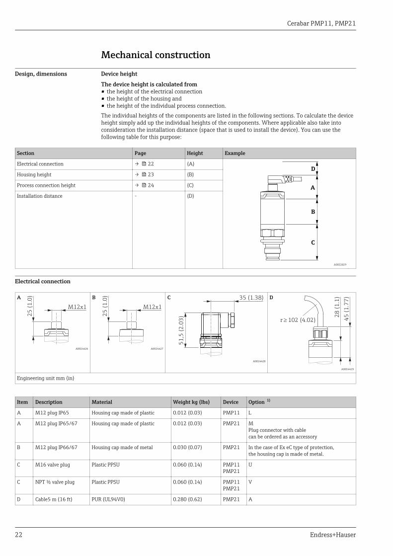
Design, dimensions Device height
The device height is calculated from• the height of the electrical connection• the height of the housing and• the height of the individual process connection.The individual heights of the components are listed in the following sections. To calculate the deviceheight simply add up the individual heights of the components. Where applicable also take intoconsideration the installation distance (space that is used to install the device). You can use thefollowing table for this purpose:
Section Page Height Example
Electrical connection → 22 (A)
A
D
B
C
A0022829
Housing height → 23 (B)
Process connection height → 24 (C)
Installation distance - (D)
Electrical connection
A
25
(1
.0)
M12x1
A0024426
B
25
(1
.0)
M12x1
A0024427
C 35 (1.38)
51
,5 (
2.0
3)
A0024428
D
28
(1
.1)
45
(1
.77
)
r ³ 102 (4.02)
A0024429
Engineering unit mm (in)
Item Description Material Weight kg (lbs) Device Option 1)
A M12 plug IP65 Housing cap made of plastic 0.012 (0.03) PMP11 L
A M12 plug IP65/67 Housing cap made of plastic 0.012 (0.03) PMP21 MPlug connector with cablecan be ordered as an accessory
B M12 plug IP66/67 Housing cap made of metal 0.030 (0.07) PMP21 In the case of Ex eC type of protection,the housing cap is made of metal.
C M16 valve plug Plastic PPSU 0.060 (0.14) PMP11PMP21
U
C NPT ½ valve plug Plastic PPSU 0.060 (0.14) PMP11PMP21
V
D Cable5 m (16 ft) PUR (UL94V0) 0.280 (0.62) PMP21 A
Cerabar PMP11, PMP21
Endress+Hauser 23
Item Description Material Weight kg (lbs) Device Option 1)
D Cable10 m (33 ft) PUR (UL94V0) 0.570 (1.26) PMP21 B
D Cable25 m (82 ft) PUR (UL94V0) 1,400 (3.09) PMP21 C
1) Product Configurator, order code for "Electrical connection"
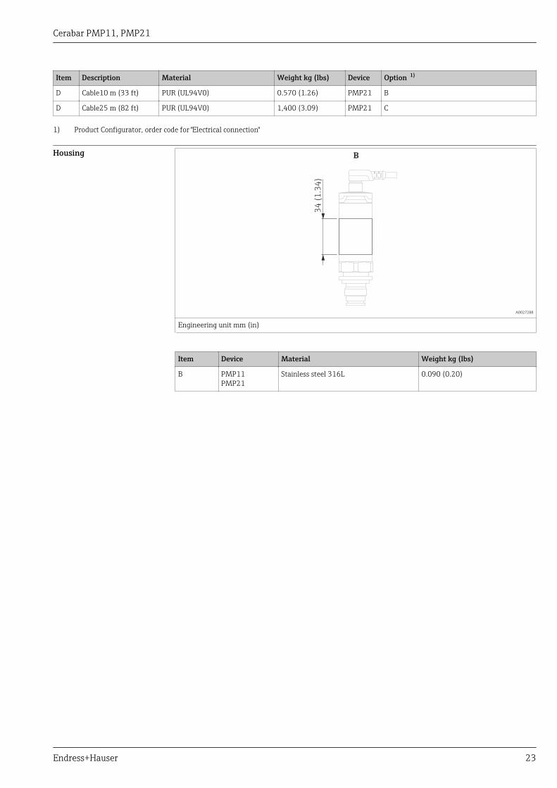
Housing
34
(1
.34
)
B
A0027288
Engineering unit mm (in)
Item Device Material Weight kg (lbs)
B PMP11PMP21
Stainless steel 316L 0.090 (0.20)
Cerabar PMP11, PMP21
24 Endress+Hauser
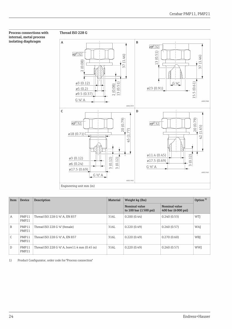
Process connections withinternal, metal processisolating diaphragm
Thread ISO 228 G
A
13
(0
.51
)
37
(1
.46
)
2 (
0.0
8)
ø3 (0.12)
ø5 (0.2)
ø9.5 (0.37)
G ¼" A
2 (
0.0
8)
32
A0021959
B
ø23 (0.91)
37
(1
.46
)
15
.5 (
0.6
1)
13
(0
.51
)
G ¼"
32
A0021960
C3
(0
.12
)
ø17.5 (0.69)
ø6 (0.24)
ø3 (0.12)
G ½" A
45
(1
.77
)
20
(0
.79
)
ø18 (0.71)
3 (
0.1
2)
32
A0021962
D
ø17.5 (0.69)
G ½" A
20
(0
.79
)
42
(1
.65
)
3 (
0.1
2)ø11.4 (0.45)
32
A0021963
Engineering unit mm (in)
Item Device Description Material Weight kg (lbs) Option 1)
Nominal valueto 100 bar (1 500 psi)
Nominal value400 bar (6 000 psi)
A PMP11PMP21
Thread ISO 228 G ¼" A, EN 837 316L 0.200 (0.44) 0.240 (0.53) WTJ
B PMP11PMP21
Thread ISO 228 G ¼" (female) 316L 0.220 (0.49) 0.260 (0.57) WAJ
C PMP11PMP21
Thread ISO 228 G ½" A, EN 837 316L 0.220 (0.49) 0.270 (0.60) WBJ
D PMP11PMP21
Thread ISO 228 G ½" A, bore11.4 mm (0.45 in) 316L 0.220 (0.49) 0.260 (0.57) WWJ
1) Product Configurator, order code for "Process connection"
Cerabar PMP11, PMP21
Endress+Hauser 25
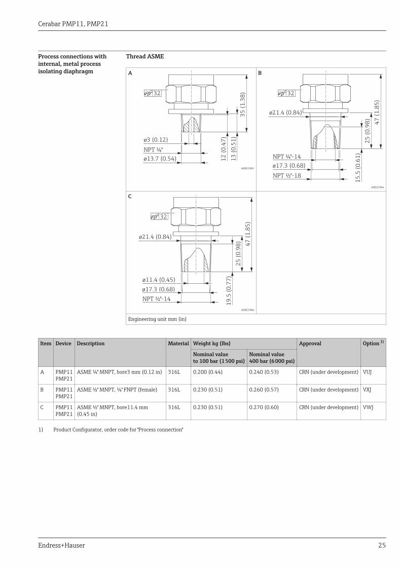
Process connections withinternal, metal processisolating diaphragm
Thread ASME
A
35
(1
.38
)
ø13.7 (0.54)
ø3 (0.12)
NPT ¼"
32
12
(0
.47
)
13
(0
.51
)
A0021965
B
47
(1
.85
)
25
(0
.98
)
15
.5 (
0.6
1)
NPT ½"-18
NPT ¼"-14
ø17.3 (0.68)
ø21.4 (0.84)
32
A0021964
C
ø11.4 (0.45)
ø21.4 (0.84)
47
(1
.85
)
25
(0
.98
)
19
.5 (
0.7
7)
NPT ½"-14
ø17.3 (0.68)
32
A0021966
Engineering unit mm (in)
Item Device Description Material Weight kg (lbs) Approval Option 1)
Nominal valueto 100 bar (1 500 psi)
Nominal value400 bar (6 000 psi)
A PMP11PMP21
ASME ¼" MNPT, bore3 mm (0.12 in) 316L 0.200 (0.44) 0.240 (0.53) CRN (under development) VUJ
B PMP11PMP21
ASME ½" MNPT, ¼" FNPT (female) 316L 0.230 (0.51) 0.260 (0.57) CRN (under development) VXJ
C PMP11PMP21
ASME ½" MNPT, bore11.4 mm(0.45 in)
316L 0.230 (0.51) 0.270 (0.60) CRN (under development) VWJ
1) Product Configurator, order code for "Process connection"
Cerabar PMP11, PMP21
26 Endress+Hauser
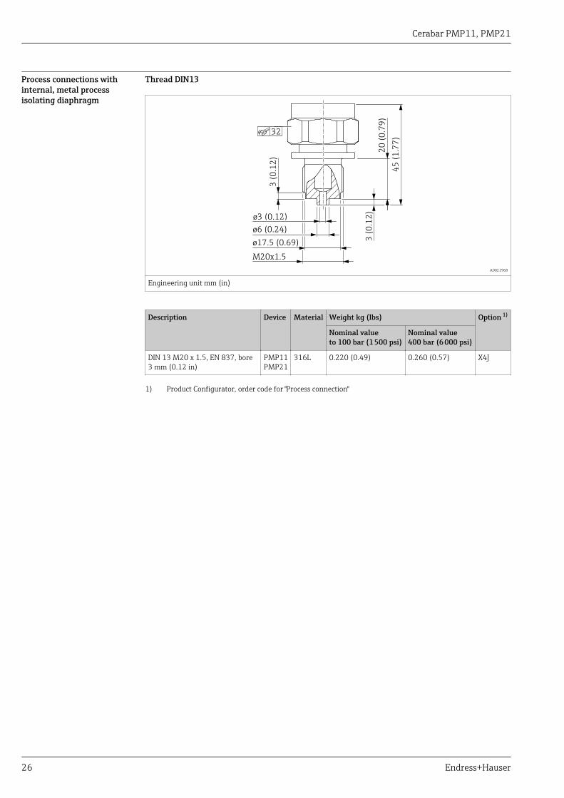
Process connections withinternal, metal processisolating diaphragm
Thread DIN13
45
(1
.77
)
20
(0
.79
)
3 (
0.1
2)
3 (
0.1
2)
M20x1.5
ø17.5 (0.69)
ø6 (0.24)
ø3 (0.12)
32
A0021968
Engineering unit mm (in)
Description Device Material Weight kg (lbs) Option 1)
Nominal valueto 100 bar (1 500 psi)
Nominal value400 bar (6 000 psi)
DIN 13 M20 x 1.5, EN 837, bore3 mm (0.12 in)
PMP11PMP21
316L 0.220 (0.49) 0.260 (0.57) X4J
1) Product Configurator, order code for "Process connection"
Cerabar PMP11, PMP21
Endress+Hauser 27
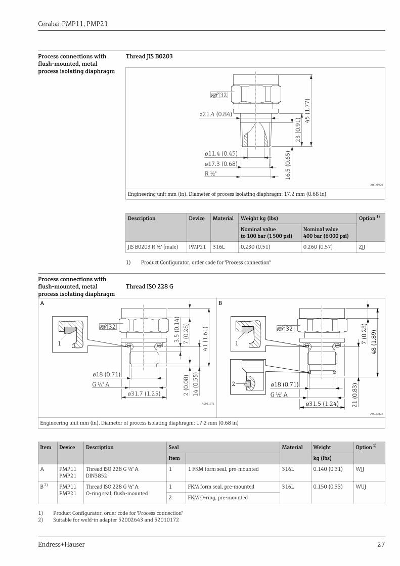
Process connections withflush-mounted, metalprocess isolating diaphragm
Thread JIS B0203
ø21.4 (0.84)
45
(1
.77
)
23
(0
.91
)
16
.5 (
0.6
5)ø11.4 (0.45)
R ½"
ø17.3 (0.68)
32
A0021970
Engineering unit mm (in). Diameter of process isolating diaphragm: 17.2 mm (0.68 in)
Description Device Material Weight kg (lbs) Option 1)
Nominal valueto 100 bar (1 500 psi)
Nominal value400 bar (6 000 psi)
JIS B0203 R ½" (male) PMP21 316L 0.230 (0.51) 0.260 (0.57) ZJJ
1) Product Configurator, order code for "Process connection"
Process connections withflush-mounted, metalprocess isolating diaphragm
Thread ISO 228 G
A
7 (
0.2
8)
ø31.7 (1.25)
ø18 (0.71)
2 (
0.0
8)
14
(0
.55
)
41
(1
.61
)
G ½" A
32
3.5
(0
.14
)
1
A0021971
B
7 (
0.2
8)
ø31.5 (1.24)
ø18 (0.71)
21
(0
.83
)
48
(1
.89
)
G ½" A
32
2
1
A0022802
Engineering unit mm (in). Diameter of process isolating diaphragm: 17.2 mm (0.68 in)
Item Device Description Seal Material Weight Option 1)
kg (lbs)Item
A PMP11PMP21
Thread ISO 228 G ½" ADIN3852
1 1 FKM form seal, pre-mounted 316L 0.140 (0.31) WJJ
B 2) PMP11PMP21
Thread ISO 228 G ½" AO-ring seal, flush-mounted
1 FKM form seal, pre-mounted 316L 0.150 (0.33) WUJ
2 FKM O-ring, pre-mounted
1) Product Configurator, order code for "Process connection"2) Suitable for weld-in adapter 52002643 and 52010172
Cerabar PMP11, PMP21
28 Endress+Hauser
Materials in contact withprocess
NOTICE‣ Device components in contact with the process are listed in the "Mechanical construction" and
"Ordering information" sections.
TSE Certificate of Suitability
The following applies to all device components in contact with the process:
• They do not contain any materials derived from animals.• No additives or operating materials derived from animals are used in production or processing.
Process connections
Endress+Hauser supplies a threaded connection made of stainless steel in accordance with AISI 316L(DIN/ EN material number 1.4404 or 1.4435). With regard to their stability-temperature property,the materials 1.4404 and 1.4435 are grouped together under 13E0 in EN 1092-1: 2001 Tab. 18.The chemical composition of the two materials can be identical.
Process isolating diaphragm
Description Material
Metal process isolating diaphragm AISI 316L (DIN/EN material number 1.4435)
Seals
See the specific process connection.
Cerabar PMP11, PMP21
Endress+Hauser 29
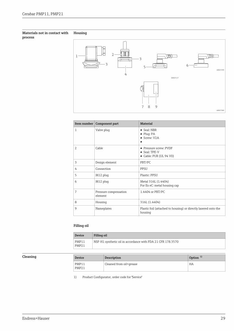
Materials not in contact withprocess
Housing
5
2
4
31
3
A0025117
6
A0027299
8 97 A0027300
Item number Component part Material
1 Valve plug • Seal: NBR• Plug: PA• Screw: V2A•
2 Cable • Pressure screw: PVDF• Seal: TPE-V• Cable: PUR (UL 94 V0)
3 Design element PBT/PC
4 Connection PPSU
5 M12 plug Plastic: PPSU
6 M12 plug Metal 316L (1.4404)For Ex eC: metal housing cap
7 Pressure compensationelement
1.4404 or PBT/PC
8 Housing 316L (1.4404)
9 Nameplates Plastic foil (attached to housing) or directly lasered onto thehousing
Filling oil
Device Filling oil
PMP11PMP21
NSF-H1 synthetic oil in accordance with FDA 21 CFR 178.3570
Cleaning Device Description Option 1)
PMP11PMP21
Cleaned from oil+grease HA
1) Product Configurator, order code for "Service"

Cerabar PMP11, PMP21
30 Endress+Hauser
Operability
Plug-on display PHX20(optional)
No display or other operation facility is required to operate the device. However, devices with a valveplug can be fitted with the optional local display PHX20.
Description Option 1)
Plug-on display PHX20, IP65 RU
1) Product Configurator, order code for "Accessories"
A 1-line liquid crystal display (LCD) is used. The local display shows measured values, fault messagesand information messages. The device display can be turned in 90° steps. Depending on theorientation of the device, it is therefore easy to read the measured values.
Technical data
Display: 4-digit, red LED display
Digit height: 7.62 mm; programmable decimal point setting
Display range: -1999 to 9999
Accuracy: 0.2% of the span ±1 digit
Electrical connection: To transmitter with 4 to 20 mA output and elbow plug DIN 43 650,reverse polarity protection
Display power supply: Not required, powered automatically from the power loop
Voltage drop: ≤ 5 V (corresponds to load: max. 250 Ω)
Rate of conversion: 3 measurements per second
Damping: 0.3 to 20 s (configurable)
Data backup: Non-volatile EEPROM
Error message: • HI: overrange• LO: below range
Programming: Via 2 keys, menu-guided, display range scaling, decimal point, damping,error message
Degree of protection: IP 65
Influence of temperature on thedisplay:
0.1% / 10 K
Electromagnetic compatibility(EMC):
Interference emission as per EN 50081, interference immunity as per EN50082
Permitted current load: Max. 60 mA
Ambient temperature: 0 to +60 °C (+32 to +140 °F)
Housing material: Pa6 GF30 plastic, blueFront screen made from red PMMA
Order number: 52022914
Cerabar PMP11, PMP21
Endress+Hauser 31
Certificates and approvals
CE mark The device meets the legal requirements of the relevant EC directives. Endress+Hauser confirms thatthe device has been successfully tested by applying the CE mark.
RCM-Tick marking The supplied product or measuring system meets the ACMA (Australian Communications and MediaAuthority) requirements for network integrity, interoperability, performance characteristics as wellas health and safety regulations. Here, especially the regulatory arrangements for electromagneticcompatibility are met. The products are labelled with the RCM- Tick marking on the name plate.
A0029561
Approval CSA C/US General Purpose
Safety Instructions (XA) Safety Instructions (XA) are supplied with the device depending on the approval. These instructionsare an integral part of the Operating Instructions.
Device Directive Documentation Option 1)
PMP21 ATEX II 1/2G Ex ia IIC T4 Ga/Gb XA01271P BA
PMP21 ATEX II 3G Ex ec IIC T4 Gc XA01533P BC
PMP21 FM IS Cl. I, Div.1 Gr. A-D T4 XA01321P FA
PMP21 CSA C/US IS Cl. I Div. 1 Gr. A-D XA01322P CB
PMP21 EAC Ex ia IIC T4 Ga/Gb In preparation GA
PMP21 IEC Ex ia IIC T4 Ga/Gb XA01271P IA
PMP21 NEPSI Ex ia IIC T4 XA01363P NA
PMP21 TIIS Ex ia IIC T4 In preparation TA
1) Product Configurator, order code for "Approval"
The nameplate provides information on the Safety Instructions (XA) that are relevant for thedevice.
Marine approval (pending) Device Description Option 1)
PMP21 DNV GL LE
PMP21 ABS LF
1) Product Configurator, order code for "Additional approval"
Pressure EquipmentDirective (PED)
The device corresponds to Article 3 (3) of the EC directive 97/23/EC (Pressure Equipment Directive)and has been designed and manufactured in accordance with good engineering practice or complieswith Category I or II, SEP.
Other standards andguidelines
The applicable European guidelines and standards can be found in the relevant EU Declarations ofConformity. The following were also applied:
DIN EN 60770 (IEC 60770):
Transmitters for use in industrial process control systems Part 1: Methods for performanceevaluation
Methods for evaluating the performance of transmitters for control and regulation in industrialprocess control systems.
Cerabar PMP11, PMP21
32 Endress+Hauser
DIN 16086:
Electrical pressure measuring instruments, pressure sensors, pressure transmitters, pressuremeasuring instruments, concepts, specifications on data sheets
Procedure for writing specifications in data sheets for electrical pressure measuring instruments,pressure sensors and pressure transmitters.
EN 61326-X:
EMC product family standard for electrical equipment for measurement, control and laboratory use.
EN 60529:
Degrees of protection provided by enclosures (IP code)
NAMUR - User association of automation technology in process industries.
NE21 - Electromagnetic Compatibility (EMC) of Industrial Process and Laboratory ControlEquipment.
NE43 - Standardization of the Signal Level for the Failure Information of Digital Transmitters.
NE44 - Standardization of Status Indicators on PCT Instruments with the Help of Light EmittingDiodes
NE53 - Software of Field Devices and Signal-processing Devices with Digital Electronics
CRN approval A CRN approval is available for some device versions. A CRN-approved process connection with aCSA approval must be ordered for a CRN-approved device. The CRN-approved devices are assignedthe registration number 0F18141.5C.
Ordering information: Product Configurator, order code for "Process connection" (the CRN processconnections are indicated appropriately in the "Mechanical construction" section.)
Calibration unit Description Option 1)
Sensor range; % A
Sensor range; mbar/bar B
Sensor range; kPa/MPa C
Sensor range; psi F
Customer-specific; see additional spec. J
1) Product Configurator, order code for "Calibration; unit"
Calibration Description Option 1)
3-point certificate of calibration F3
1) Product Configurator order code for "Calibration"
Inspection certificates Device Description Option 1)
PMP21 3.1 Material documentation, wetted metal parts, EN10204-3.1 inspection certificate JA
1) Product Configurator, order code for "Test, Certificate"
Cerabar PMP11, PMP21
Endress+Hauser 33
Ordering informationDetailed ordering information is available from the following sources:• In the Product Configurator on the Endress+Hauser website: www.endress.com -> Click "Corporate"
-> Select your country -> Click "Products" -> Select the product using the filters and search field ->Open product page -> The "Configure" button to the right of the product image opens the ProductConfigurator.
• From your Endress+Hauser Sales Center: www.addresses.endress.comProduct Configurator - the tool for individual product configuration• Up-to-the-minute configuration data• Depending on the device: Direct input of measuring point-specific information such as
measuring range or operating language• Automatic verification of exclusion criteria• Automatic creation of the order code and its breakdown in PDF or Excel output format• Ability to order directly in the Endress+Hauser Online Shop
Scope of delivery • Measuring device• Optional accessories• Brief Operating Instructions• Certificates

Cerabar PMP11, PMP21
34 Endress+Hauser
Accessories
Weld-in adapter Various weld-in adapters are available for installation in vessels or pipes.
Device Description Option 1) Order number
PMP21 Weld-in adapter G½, 316L QA 52002643
PMP21 Weld-in adapter G½, 316L 3.1 EN10204-3.1 material,inspection certificate
QB 52010172
PMP21 Weld-in tool adapter G½, brass QC 52005082
1) Product Configurator, order code for "Enclosed accessories"
If installed horizontally and weld-in adapters with a leakage hole are used, ensure that the leakagehole is pointing down. This allows leaks to be detected as quickly as possible.
Plug-on display PHX20 → 30
M12 plug connectors Connector Degree of protection Material Option 1) Order number
M12(self-terminated connectionat M12 plug)
53 (2.09)
ø2
0
(0.8
)
A0024475
IP67 • Union nut: Cu Sn/Ni• Body: PBT• Seal: NBR
R1 52006263
M12 90 degreeswith 5m (16 ft) cable
28
(1.1
)
40 (1.57)³
A0024476
IP67 • Union nut: GD Zn/Ni• Body: PUR• Cable: PVC
RZ 52010285
M12 90 degrees(self-terminated connectionat M12 plug)
35
(1.3
8)
28
(1.1)
20 (0.79)
A0024478
IP67 • Union nut: GD Zn/Ni• Body: PBT• Seal: NBR
RM 71114212
1) Product Configurator, order code for "Enclosed accessories"
Cerabar PMP11, PMP21
Endress+Hauser 35
Documentation
Field of Activities Pressure measurement, powerful instruments for process pressure, differential pressure, level andflow:
FA00004P/00/EN
Technical Information • TI00241F/00/DE: EMV test procedures• TI00426F/00/DE: Weld-in adapters, process adapters and flanges (overview)
Operating Instructions BA01271P/00/EN
Brief Operating Instructions KA01164P/00/EN
Safety Instructions (XA) Safety Instructions (XA) are supplied with the device depending on the approval. These instructionsare an integral part of the Operating Instructions.
Device Directive Documentation Option 1)
PMP21 ATEX II 1/2G Ex ia IIC T4 Ga/Gb XA01271P BA
PMP21 ATEX II 3G Ex ec IIC T4 Gc XA01533P BC
PMP21 FM IS Cl. I, Div.1 Gr. A-D T4 XA01321P FA
PMP21 CSA C/US IS Cl. I Div. 1 Gr. A-D XA01322P CB
PMP21 EAC Ex ia IIC T4 Ga/Gb In preparation GA
PMP21 IEC Ex ia IIC T4 Ga/Gb XA01271P IA
PMP21 NEPSI Ex ia IIC T4 XA01363P NA
PMP21 TIIS Ex ia IIC T4 In preparation TA
1) Product Configurator, order code for "Approval"
The nameplate provides information on the Safety Instructions (XA) that are relevant for thedevice.

www.addresses.endress.com
*71326741*71326741