Embed Size (px)
Citation preview
Experimental Validation and Application of CFD and CMFD Codes to Nuclear Reactor Safety Issues (XCFD4NRS-3)
Washington D.C., USA, 14-16 September , 2010.
1
CFD modeling of wall steam condensation:
two phase flow approach versus homogeneous flow approach
S. Mimouni, N. Mechitoua, A. Foissac
Electricité de France R&D Division
6, Quai Watier 78400 Chatou Cedex France
M. Hassanaly, M. Ouraou
INCKA
85, avenue Pierre Grenier 92100 Boulogne Billancourt
ABSTRACT Condensation heat transfer in the presence of non-condensable gases is a relevant phenomenon in
many industrial applications. The present work is focused on the condensation heat transfer that plays
a dominant role in many accident scenarios postulated to occur in the containment of nuclear reactors.
The aim of the study is to contribute to the understanding of the heat and mass transfer mechanisms
involved in the problem. The study also compares a general multiphase approach implemented in
NEPTUNE_CFD with a homogeneous model, of widespread use for engineering studies, implemented
in Code_Saturne. The NEPTUNE_CFD code is developed within the framework of the NEPTUNE
project, financially supported by CEA (Commissariat à l'Énergie Atomique), EDF, IRSN (Institut de
Radioprotection et de Sûreté Nucléaire) and AREVA-NP.
The model implemented in NEPTUNE_CFD assumes that liquid droplets form along the wall within
nucleation sites. Vapor condensation on droplets makes grow. Once the droplet diameter reaches a
critical value, gravitational forces compensate surface tension force and then droplets slide over the
wall. Droplets can also join the neighbouring droplets and form a liquid film. The starting point of the
model is based on the balance of heat and mass transfer between droplets and the gas mixture
surrounding the droplets. Each fluid (gas mixture or droplets) is modeled through at least 3
conservation equations representing mass, momentum and total enthalpy. This approach allows taking
into account simultaneously the mechanical drift between the droplet and the gas, the heat and mass
transfer on droplets in the core of the flow and the condensation/evaporation phenomena on the walls.
The homogeneous condensation heat transfer implemented in Code_Saturne is modeled through a
mass transfer between the steam and the water liquid. This term depends on the difference between the
non condensable gas mass fractions at the gas/liquid interface (wall) and in the fluid. The exchange
coefficient is given by correlations based upon boundary layers laws driven by free or forced
convection. The creation of liquid mass is taken into account through a sink term in the steam mass
conservation equation and the global mass equation of the gases. The motion of the liquid film due to
the gravitational forces is neglected, as well as the volume occupied by the liquid.
Both condensation models and compressible procedures are validated and compared to experimental
data provided by the TOSQAN ISP47 experiment (IRSN Saclay). Computational results compare
favorably with experimental data, particularly for the Helium and steam volume fractions.
Nevertheless, the cross-comparison of the gas velocity profiles should be improved in plume-jet
configuration. It concerns turbulence modeling for accurate predictions of heat transfer in the whole
containment. The NEA/CSNI Best Practice Guidelines were followed as much as possible, especially
in the mesh generation process by keeping acceptable quality for the grids, by exploring the grid
convergence, and also by assessing the numerical convergence.
1 INTRODUCTION
Condensation heat transfer in the presence of noncondensable gases is a relevant phenomenon in many
industrial applications, including nuclear reactors.
Experimental Validation and Application of CFD and CMFD Codes to Nuclear Reactor Safety Issues (XCFD4NRS-3)
Washington D.C., USA, 14-16 September , 2010.
2
In particular, during the course of a hypothetical severe accident in a nuclear Pressurized Water
Reactor (PWR), hydrogen may be produced by the reactor core oxidation and distributed into the
reactor containment according to convective flows, water steam wall condensation and interaction
with the spraying droplets. In order to assess the risk of detonation generated by a high local hydrogen
concentration, hydrogen distribution in the containment vessel has to be known. The TOSQAN
experimental programme (Vendel, 2007) has been created to simulate typical accidental thermal
hydraulic flow conditions of the reactor containment. The heat and mass exchanges between the spray
droplets and the gas with thermal hydraulic conditions representative of this hypothetical severe
accident has been studied in (Mimouni, 2009b). The aim of this work is thus to study the wall
condensation.
To evaluate the condensation modelling of containment codes, ISP47 test was performed in the
TOSQAN facility (OECD). The TOSQAN facility is a large enclosure devoted to simulate typical
accidental thermal hydraulic flow conditions in PWR containment. It is highly instrumented with non-
intrusive optical diagnostics. Therefore, it is particularly adapted to nuclear safety CFD code
validation.
This issue has already been addressed by using computational fluid dynamics (CFD) codes as CFX
code (Kljenak, 2006). In these calculations, the flow is modelled as single-phase and the condensation
acts as a sink of mass and energy. In this approach, the liquid film and the influence of the non
condensable gas layer are reduced to a simple sink term. On the other hand, the use of explicit
correlations to evaluate heat and mass transfer processes, though it represents a feasible approach for
large experimental facilities and reactor plant containments, partly ignores the useful information
provided by the detailed CFD models in relation to local conditions.
Another modelling is proposed in (Forgione, 2005). With this approach, heat and mass correlations are
replaced by using “fundamental” physical laws. But, in that case, a very fine computational grid is
required: the adopted two-dimensional grid discretizes the vessel gas region of TOSQAN experiment
in about 28500 cells instead of 4800 for the former case.
The main objective of the paper is to propose a novel condensation model based on “fundamental”
physical laws without requiring a very fine computational grid: 7500 cells are used for TOSQAN
ISP47 test and the grid is uniform. In reactor applications, droplets at the wall come from vapor
condensation or sprays. The computation of heat and mass transfer between a spray and a gas mixture
has already been addressed (Mimouni, 2009b).
In fact, thanks to a code–to-experiment benchmark based on 2 tests of the TOSQAN facility (Malet,
2008), we successfully evaluated the ability of the code to reproduce the droplet heat and mass transfer
on one hand (TOSQAN 101 case) and the gas entrainment and atmosphere mixing by the spray on the
other hand (TOSQAN 113 case). An novel model dedicated to the droplet evaporation at the wall was
also proposed (Mimouni, 2009b). As a consequence, the vapor condensation model can be seen as an
extension of the previous model.
Moreover, it is of primary importance to take into account both evaporation and condensation
phenomena. In fact, Andreani et al. (Andreani, 2008) underline that depending on the break location
and the geometry of the containment, liquid films could flow into dry regions where the liquid would
evaporate. If walls are hotter than the liquid film, this would result in an enhanced evaporation rate.
The paper is organized as follows. First we describe briefly the set of equations solved in the
NEPTUNE_CFD and Code_Saturne codes. In the last part, the two-phase flow model and the
homogenous models are compared and validated by simulating the TOSQAN ISP47 test on global and
local variables. Both models have been already validated against COPAIN test (Mimouni, 2010).
2 THE NUMERICAL SOLVER AND PHYSICAL MODELING : NEPTUNE_CFD CODE
The solver belongs to the well-known class of pressure based methods. It is able to simulate multi-
component multiphase flows by solving a set of three balance equations for each field (fluid
Experimental Validation and Application of CFD and CMFD Codes to Nuclear Reactor Safety Issues (XCFD4NRS-3)
Washington D.C., USA, 14-16 September , 2010.
3
component and/or phase) (Ishii, 1975), (Delhaye, 1981). These fields can represent many kinds of
multiphase flows: distinct physical components (e.g. gas, liquid and solid particles); thermodynamic
phases of the same component (e.g.: liquid water and its vapour); distinct physical components, some
of which split into different groups (e.g.: water and several groups of different diameter bubbles);
different forms of the same physical components (e.g.: a continuous liquid field, a dispersed liquid
field, a continuous vapour field, a dispersed vapour field). The solver is implemented in the
NEPTUNE software environment (Guelfi, 2007), (Mimouni, 2008), which is based on a finite volume
discretization, together with a collocated arrangement for all variables. The data structure is totally
face-based which allows the use of arbitrary shaped cells (tetraedra, hexaedra, prisms, pyramids ...)
including non-conformal meshes.
The main interest of the numerical method is the so-called “volume fraction – pressure – energy cycle”
that ensures mass and energy conservation and allows strong interface source term coupling
(Mechitoua, 2003).
Mass balance equations, momentum balance equations and total enthalpy balance equations are solved
for each phase. The gas turbulence is taken into account by the classical k- model. The droplet
diameter evolution is calculated from an equation of transport on the density of drops. Additional
equations are added to take into account the non-condensable gases (air and helium). As concern the
interfacial momentum transfer terms, the only force exerted on droplet is the drag force. Small droplets
stick at the wall and large drop slide along the wall under the competition between the surface tension
and the gravity force. As a consequence, the gas velocity near the wall does not tend to zero but to the
droplets velocity because of the drag force. This is a major difference between single-phase and two-
phase flow approach (Mimouni, 2010). As concern the heat and mass transfer between droplets and
the wall, it is based on the balance of heat and mass transfer between a drop and the gas mixture
surrounding the drop using the correlations of Frössling/Ranz-Marshall which are of widespread use.
The model of drop-wall interaction which was developed and implemented is written as a symmetric
extension of the nucleate boiling model at the wall, and uses as a starting point the model of mass
transfer in the core flow. To establish this model, we made the following assumptions:
- the drops which accumulate on the walls take a hemispherical form;
- there is no nucleate boiling inside the drops at the wall;
- the drops which impact the walls successively see a stage of cooling (resp. heating) and a
stage of condensation (resp. evaporation);
- the droplets stick to the wall (no rebound), or slide along the wall.
The total heat flux exchanged between the wall and the flow is split into four terms:
• 1C a single-phase flow convective heat flux at the fraction of the wall area unaffected by the
presence of droplets (heat transfer between the gas and the wall);
• 2C a single-phase flow convective heat flux at the fraction of the wall area affected by the presence
of a liquid film (heat transfer between the liquid film and the wall);
• Th a single-phase flow heat flux to decrease (resp. increase) the droplet temperature and reach the
wall temperature (resp. the saturation state) (heat transfer between the droplets and the wall);
• E a condensation (resp. vaporisation) heat flux.
Details can be found in (Mimouni, 2010). An extensive validation process has been achieved in
(Mimouni, 2010) against the COPAIN experiment and mesh sensitivity has been found acceptable.
3 HOMOGENEOUS GAS DYNAMIC MODEL USED IN CODE_SATURNE
The motion of gases and heat transfer in containment enclosures can be described by the general
momentum, partial masses and energy conservation equations (Williams, 1985).
The predominant physical phenomena driving the distribution and heat transfer of fluids within
containment enclosures are the following:
Mixing and / or segregation of gas whose velocity, density and temperature are different.
"Swelling" of containment: the compressibility of gas is taken into account, even if the flow
velocities are low.
Experimental Validation and Application of CFD and CMFD Codes to Nuclear Reactor Safety Issues (XCFD4NRS-3)
Washington D.C., USA, 14-16 September , 2010.
4
Laminar and controlled combustion of hydrogen in recombiners, in order to limit the
concentration of this gas.
Condensation of steam on cold structure surfaces, which has the main effect of limiting the
pressure rise.
The general momentum, partial masses and energy conservation equations describing these
phenomena can be simplified and stiffness due to the presence of physics having very different
characteristic length and time scales can be removed or relaxed.
Steam condensation on the walls of the containment enclosure plays a key role in the dynamic and
heat transfer. The heat and mass sink terms of gases due to condensation are modeled through
correlations based on heat and mass transfer analogy of Chilton-Colburn type. The liquid film is not
modeled and it is assumed that vapor and non condensable gases are in direct contact with the wall.
The modelling of the heat transfer by condensation of steam in liquid can be found in (Mechitoua,
2010).
4 TOSQAN FACILITY
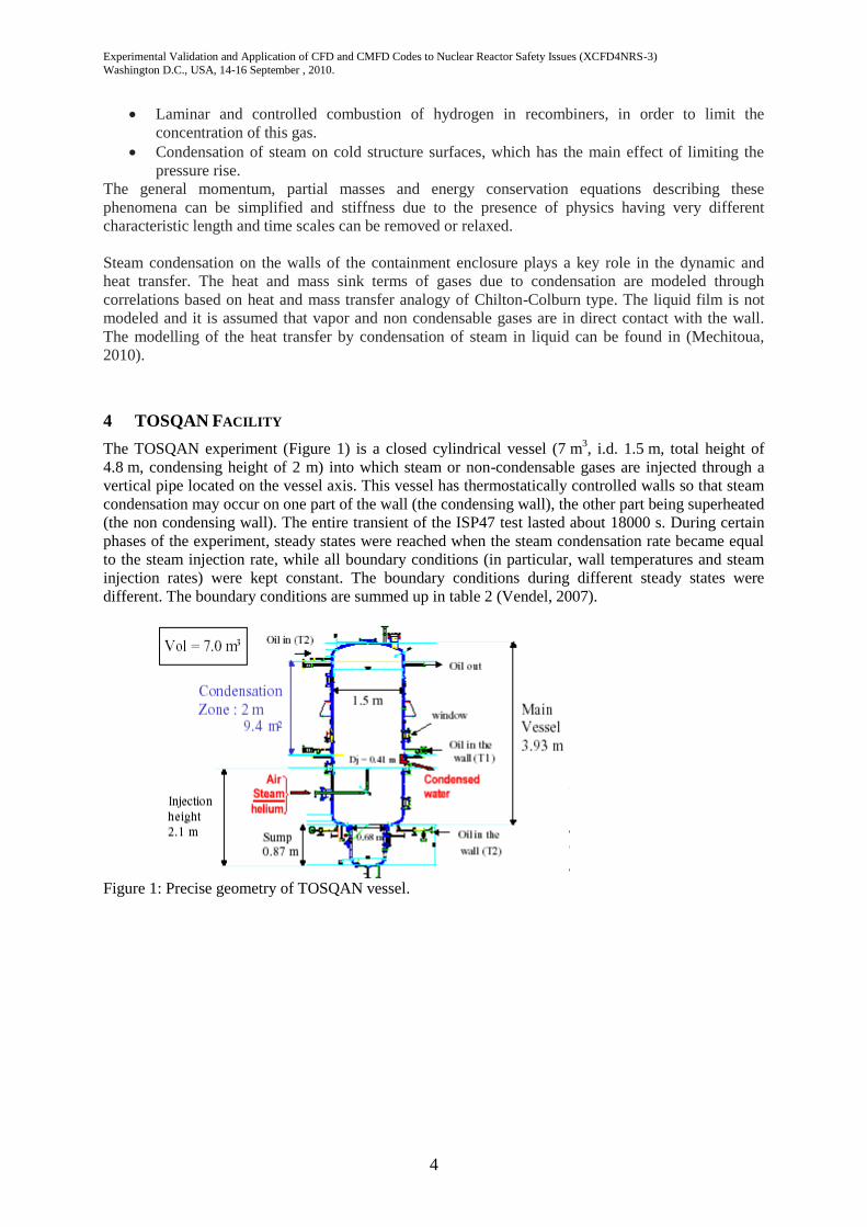
The TOSQAN experiment (Figure 1) is a closed cylindrical vessel (7 m3, i.d. 1.5 m, total height of
4.8 m, condensing height of 2 m) into which steam or non-condensable gases are injected through a
vertical pipe located on the vessel axis. This vessel has thermostatically controlled walls so that steam
condensation may occur on one part of the wall (the condensing wall), the other part being superheated
(the non condensing wall). The entire transient of the ISP47 test lasted about 18000 s. During certain
phases of the experiment, steady states were reached when the steam condensation rate became equal
to the steam injection rate, while all boundary conditions (in particular, wall temperatures and steam
injection rates) were kept constant. The boundary conditions during different steady states were
different. The boundary conditions are summed up in table 2 (Vendel, 2007).
Figure 1: Precise geometry of TOSQAN vessel.

Experimental Validation and Application of CFD and CMFD Codes to Nuclear Reactor Safety Issues (XCFD4NRS-3)
Washington D.C., USA, 14-16 September , 2010.
5
Figure 2: Fields of axial velocity, gas temperature and iso-values of steam molar concentration.
The initial conditions for the thermo-fluid-dynamic variables necessary to start the simulation of the
transient were evaluated through a preliminary calculation, with no mass flow rate at the inlet section
and with only air present inside the vessel.
The mean upper (resp. lower) non condensing wall temperature is maintained constant and equal to
122.0°C +/-1 (resp. 123.5°C +/-1) during the whole test.
Gas temperature, volume fractions and gas velocity measurements are available on TOSQAN at
different heights Z. The flow is assumed to be axi-symmetric so that a two-dimensional axi-symmetric
mesh is used. Two-dimensional representations of axial velocity and gas temperature are illustrated on
Figure 2. Computations have been performed on two kinds of meshing: a grid with 7500 cells (average
size of 2 cm) and a fine grid with 32000 cells (average size of 1 cm). Results are similar (Figure 5)
between “standard” (4460 cells) and fine mesh (32000 cells). Hence, the subsequent computations are
performed on the coarse grid. Calculations performed with Code_Saturne use about 1700 cells.
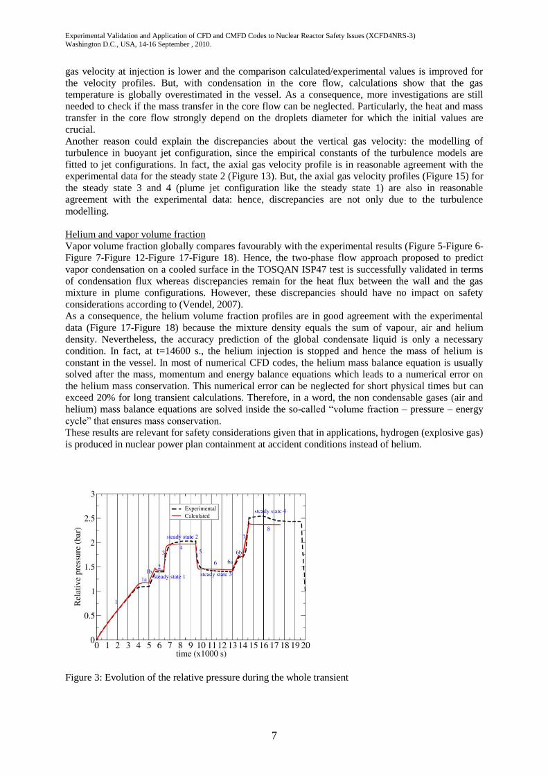
The evolution of the relative pressure during the whole transient is illustrated by Figure 3 and
compares quite favourably with experimental data. This figure gives a general idea of the successive
stages.
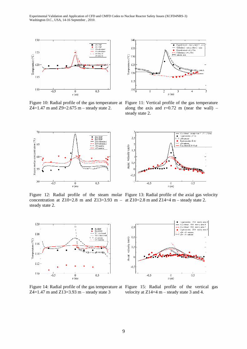
Gas temperature profiles
The gas temperature compares favourably with experimental results in the lower part of the TOSQAN
vessel but is overestimated in the upper part in plume or jet-plume configuration (Figure 8-Figure 9-
Figure 14-Figure 16). In jet configuration, the gas temperature profiles are in good agreement with the
experimental data, including near the wall (Figure 10-Figure 11).
Experimental Validation and Application of CFD and CMFD Codes to Nuclear Reactor Safety Issues (XCFD4NRS-3)
Washington D.C., USA, 14-16 September , 2010.
6
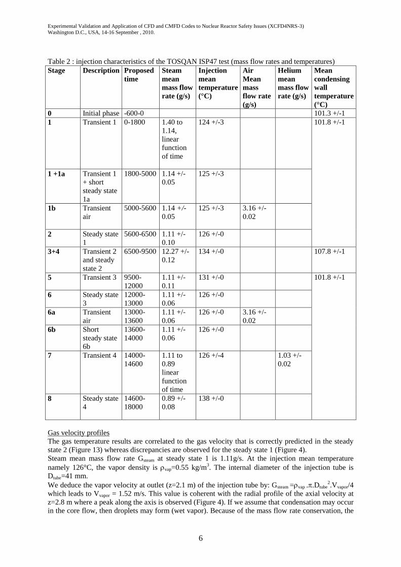
Table 2 : injection characteristics of the TOSQAN ISP47 test (mass flow rates and temperatures)
Stage
Description
Proposed
time
Steam
mean
mass flow
rate (g/s)
Injection
mean
temperature
(°C)
Air
Mean
mass
flow rate
(g/s)
Helium
mean
mass flow
rate (g/s)
Mean
condensing
wall
temperature
(°C)
0 Initial phase -600-0 101.3 +/-1
1 Transient 1
0-1800 1.40 to
1.14,
linear
function
of time
124 +/-3 101.8 +/-1
1 +1a Transient 1
+ short
steady state
1a
1800-5000 1.14 +/-
0.05
125 +/-3
1b Transient
air
5000-5600 1.14 +/-
0.05
125 +/-3 3.16 +/-
0.02
2 Steady state
1
5600-6500 1.11 +/-
0.10
126 +/-0
3+4 Transient 2
and steady
state 2
6500-9500 12.27 +/-
0.12
134 +/-0 107.8 +/-1
5 Transient 3 9500-
12000
1.11 +/-
0.11
131 +/-0 101.8 +/-1
6 Steady state
3
12000-
13000
1.11 +/-
0.06
126 +/-0
6a Transient
air
13000-
13600
1.11 +/-
0.06
126 +/-0 3.16 +/-
0.02
6b Short
steady state
6b
13600-
14000
1.11 +/-
0.06
126 +/-0
7 Transient 4 14000-
14600
1.11 to
0.89
linear
function
of time
126 +/-4 1.03 +/-
0.02
8 Steady state
4
14600-
18000
0.89 +/-
0.08
138 +/-0
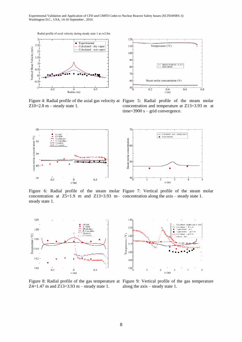
Gas velocity profiles
The gas temperature results are correlated to the gas velocity that is correctly predicted in the steady
state 2 (Figure 13) whereas discrepancies are observed for the steady state 1 (Figure 4).
Steam mean mass flow rate Gsteam at steady state 1 is 1.11g/s. At the injection mean temperature
namely 126°C, the vapor density is vap=0.55 kg/m3. The internal diameter of the injection tube is
Dtube=41 mm.
We deduce the vapor velocity at outlet (z=2.1 m) of the injection tube by: Gsteam =vap ..Dtube2.Vvapor/4
which leads to Vvapor = 1.52 m/s. This value is coherent with the radial profile of the axial velocity at
z=2.8 m where a peak along the axis is observed (Figure 4). If we assume that condensation may occur
in the core flow, then droplets may form (wet vapor). Because of the mass flow rate conservation, the
Experimental Validation and Application of CFD and CMFD Codes to Nuclear Reactor Safety Issues (XCFD4NRS-3)
Washington D.C., USA, 14-16 September , 2010.
7
gas velocity at injection is lower and the comparison calculated/experimental values is improved for
the velocity profiles. But, with condensation in the core flow, calculations show that the gas
temperature is globally overestimated in the vessel. As a consequence, more investigations are still
needed to check if the mass transfer in the core flow can be neglected. Particularly, the heat and mass
transfer in the core flow strongly depend on the droplets diameter for which the initial values are
crucial.
Another reason could explain the discrepancies about the vertical gas velocity: the modelling of
turbulence in buoyant jet configuration, since the empirical constants of the turbulence models are
fitted to jet configurations. In fact, the axial gas velocity profile is in reasonable agreement with the
experimental data for the steady state 2 (Figure 13). But, the axial gas velocity profiles (Figure 15) for
the steady state 3 and 4 (plume jet configuration like the steady state 1) are also in reasonable
agreement with the experimental data: hence, discrepancies are not only due to the turbulence
modelling.
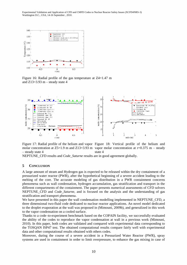
Helium and vapor volume fraction
Vapor volume fraction globally compares favourably with the experimental results (Figure 5-Figure 6-
Figure 7-Figure 12-Figure 17-Figure 18). Hence, the two-phase flow approach proposed to predict
vapor condensation on a cooled surface in the TOSQAN ISP47 test is successfully validated in terms
of condensation flux whereas discrepancies remain for the heat flux between the wall and the gas
mixture in plume configurations. However, these discrepancies should have no impact on safety
considerations according to (Vendel, 2007).
As a consequence, the helium volume fraction profiles are in good agreement with the experimental
data (Figure 17-Figure 18) because the mixture density equals the sum of vapour, air and helium
density. Nevertheless, the accuracy prediction of the global condensate liquid is only a necessary
condition. In fact, at t=14600 s., the helium injection is stopped and hence the mass of helium is
constant in the vessel. In most of numerical CFD codes, the helium mass balance equation is usually
solved after the mass, momentum and energy balance equations which leads to a numerical error on
the helium mass conservation. This numerical error can be neglected for short physical times but can
exceed 20% for long transient calculations. Therefore, in a word, the non condensable gases (air and
helium) mass balance equations are solved inside the so-called “volume fraction – pressure – energy
cycle” that ensures mass conservation.
These results are relevant for safety considerations given that in applications, hydrogen (explosive gas)
is produced in nuclear power plan containment at accident conditions instead of helium.
Figure 3: Evolution of the relative pressure during the whole transient
Experimental Validation and Application of CFD and CMFD Codes to Nuclear Reactor Safety Issues (XCFD4NRS-3)
Washington D.C., USA, 14-16 September , 2010.
8
Figure 4: Radial profile of the axial gas velocity at
Z10=2.8 m – steady state 1.
Figure 5: Radial profile of the steam molar
concentration and temperature at Z13=3.93 m at
time=3900 s – grid convergence.
Figure 6: Radial profile of the steam molar
concentration at Z5=1.9 m and Z13=3.93 m–
steady state 1.
Figure 7: Vertical profile of the steam molar
concentration along the axis – steady state 1.
Figure 8: Radial profile of the gas temperature at
Z4=1.47 m and Z13=3.93 m – steady state 1.
Figure 9: Vertical profile of the gas temperature
along the axis – steady state 1.
Experimental Validation and Application of CFD and CMFD Codes to Nuclear Reactor Safety Issues (XCFD4NRS-3)
Washington D.C., USA, 14-16 September , 2010.
9
Figure 10: Radial profile of the gas temperature at
Z4=1.47 m and Z9=2.675 m – steady state 2.
Figure 11: Vertical profile of the gas temperature
along the axis and r=0.72 m (near the wall) –
steady state 2.
Figure 12: Radial profile of the steam molar
concentration at Z10=2.8 m and Z13=3.93 m –
steady state 2.
Figure 13: Radial profile of the axial gas velocity
at Z10=2.8 m and Z14=4 m – steady state 2.
Figure 14: Radial profile of the gas temperature at
Z4=1.47 m and Z13=3.93 m – steady state 3
Figure 15: Radial profile of the vertical gas
velocity at Z14=4 m – steady state 3 and 4.
Experimental Validation and Application of CFD and CMFD Codes to Nuclear Reactor Safety Issues (XCFD4NRS-3)
Washington D.C., USA, 14-16 September , 2010.
10
Figure 16: Radial profile of the gas temperature at Z4=1.47 m
and Z13=3.93 m – steady state 4
Figure 17: Radial profile of the helium and vapor
molar concentration at Z5=1.9 m and Z13=3.93 m
– steady state 4
Figure 18: Vertical profile of the helium and
vapor molar concentration at r=0.375 m – steady
state 4
NEPTUNE_CFD results and Code_Saturne results are in good agreement globally.
5 CONCLUSION
A large amount of steam and Hydrogen gas is expected to be released within the dry containment of a
pressurized water reactor (PWR), after the hypothetical beginning of a severe accident leading to the
melting of the core. The accurate modeling of gas distribution in a PWR containment concerns
phenomena such as wall condensation, hydrogen accumulation, gas stratification and transport in the
different compartments of the containment. The paper presents numerical assessments of CFD solvers
NEPTUNE_CFD and Code_Saturne, and is focused on the analysis and the understanding of gas
stratification and transport phenomena. We have presented in this paper the wall condensation modelling implemented in NEPTUNE_CFD, a
three dimensional two-fluid code dedicated to nuclear reactor applications. An novel model dedicated
to the droplet evaporation at the wall was proposed in (Mimouni, 2009b), and generalized in this work
to the vapor condensation on a cooled surface.
Thanks to a code–to-experiment benchmark based on the COPAIN facility, we successfully evaluated
the ability of the codes to reproduce the vapor condensation at wall in a previous work (Mimouni,
2010). In this paper, both codes are validated and compared with experimental data corresponding to
the TOSQAN ISP47 test. The obtained computational results compare fairly well with experimental
data and other computational results obtained with others codes.
Moreover, during the course of a severe accident in a Pressurized Water Reactor (PWR), spray
systems are used in containment in order to limit overpressure, to enhance the gas mixing in case of
Experimental Validation and Application of CFD and CMFD Codes to Nuclear Reactor Safety Issues (XCFD4NRS-3)
Washington D.C., USA, 14-16 September , 2010.
11
the presence of hydrogen and to drive down the fission products. Hence, vapor condensation on a
cooled surface and spray effects act simultaneously in applications which is made possible with the
two-phase flow approach proposed in the paper.
Predictions regarding axial velocity do not agree in some cases because of turbulence modelling. One
alternative in further studies might be to use Reynolds Stress Transport Model to deal with turbulence
modelling (Mimouni, 2009c). Future work also concern mesh sensitivity studies comprising structured
mesh (hexahedra) or unstructured mesh (tetrahedron).
ACKNOWLEDGMENTS
This work has been achieved in the framework of the PAGODES2 project financially supported by
EDF (Electricité de France). The NEPTUNE_CFD code is being developed in the framework of the
NEPTUNE project financially supported by CEA (Commissariat à l’Energie Atomique), EDF
(Electricité de France), IRSN (Institut de Radioprotection et de Sûreté Nucléaire) and AREVA-NP.
REFERENCES
1. F. Archambeau, N. Méchitoua, M. Sakiz, Code_Saturne: a .finite volume code for the computation
of turbulent incompressible .flows – industrial applications, Int. J. Finite Vol. 1 (2004).
2. Alipchenkov, Nigmatulin, Soloviev, Stonik, Zaichik, Zeigarnik (2004), “A three-fluid model of
two-phase dispersed annular flow”, International Journal of Heat and Mass Transfer 47 (2004)
5323-5338.
3. M. Andreani, D. Paladino, T. George, “On the unespectedly large effect of the re-vaporization of
the condensate liquid film in two tests in the PANDA facility revealed by simulations with the
GOTHIC code”, XCFD4NRS, Grenoble, France, 10-12 september 2008.
4. P. Bazin, P. Castelli, “COPAIN rapport d’essais”, CEA/DRN/DTP internal report,
SETEX/LETS/99-85, 1999, in French.
5. J-M. Delhaye, M. Giot and M.L. Riethmuller, Thermal-hydraulics of two-phase systems for
industrial design and nuclear engineering,. Hemisphere and McGraw Hill, 1981.
6. A. Faghri, Y. Zhang, Transport Phenomena in Multiphase Systems, Elsevier, 2007.
7. N. Forgione, S. Paci, “Computational analysis of vapour condensation in presence of air in the
TOSQAN facility”, 11th International Topical Meeting on Nuclear Reactor Thermal-Hydraulics
(NURETH-11), Avignon, France, October 2-6, 2005.
8. A. Guelfi, D. Bestion, M. Boucker, P. Boudier, P. Fillion, M. Grandotto, J-M. Hérard, E. Hervieu,
P. Péturaud, “NEPTUNE - A new software platform for advanced nuclear thermal hydraulics”,
Nuclear Science and Engineering, vol. 156, pp. 281-324, 2007.
9. M. Ishii, Thermo-fluid dynamic, theory of two phase, Eyrolles, collection de la direction des
Etudes et recherches d’Electricité de France, 1975.
10. I. Kljenak, M. Babic, B. Mavko, I. Bajsic, « Modeling of containment atmosphere mixing and
stratification experiment using a CFD approach », Nucl. Eng. And Design (2006)
11. S. Kudriakov and al, “The TONUS CFD Code for hydrogene risk analysis: physical models
numerical schemes and validation matrix”, CFD4NRS, Garching (Munich, 2006).
12. B.E. Launder, D.B. Spalding., Numerical computation of turbulent flows. Computer Methods in
Applied Mechanics and Engineering, 3, 1974
13. B.E. Launder, Turbulence transport models for numerical computation of complex turbulent
flows. Von Karman Institute for fluid dynamics, lecture series 3, 1980
14. J. Malet, L. Blumenfeld, S. Arndt, M. Babic, A. Bentaib, F. Dabbene, P. Kostka, S. Mimouni, M.
Movahed, S. Paci, Z. Parduba, J. Travis, E. Urbonavicius, « Sprays in Containment : Final results
of the SARNET Spray Benchmark », 3rd European Review Meeting on Severe Accident Research
Experimental Validation and Application of CFD and CMFD Codes to Nuclear Reactor Safety Issues (XCFD4NRS-3)
Washington D.C., USA, 14-16 September , 2010.
12
(ERMSAR-2008), Nesseber, Bulgaria, 23-25 September 2008.
15. S. Mimouni, M. Boucker, J. Laviéville, A. Guelfi, D. Bestion, “Modeling and computation of
cavitation and boiling bubbly flows with the NEPTUNE_CFD code”, Nucl. Eng. And Design 238
(2008) pp 680-692.
16. S. Mimouni, F. Archambeau, M. Boucker, J. Lavi´eville and C.Morel., “A second order turbulence
model based on a Reynolds Stress approach for two-phase flow – Part I: adiabatic CASES”,
Sciences and Technology of Nuclear Installations, Volume 2009, Article ID 792395, 14 pages.
17. S. Mimouni J-S. Lamy, J. Lavieville, S. Guieu , M. Martin, Modelling of sprays in containment
applications with a CMFD code, Nucl. Eng. And Design, in press, available online 21 decembre
2009.
18. S. Mimouni, , F. Archambeau, M. Boucker, J. Lavieville, C. Morel, “A second order turbulence
model based on a Reynolds stress approach for two-phase boiling flow. Part 1: Application to the
ASU-anular channel case”, Nucl. Eng. And Design, in press, available online 17 decembre 2009.
19. S. Mimouni, , F. Archambeau, M. Boucker, J. Lavieville, C. Morel, “A second order turbulence
model based on a Reynolds stress approach for two-phase boiling and application to fuel assembly
analysis”, Nucl. Eng. And Design, in press, available online 24 decembre 2009.
20. S. Mimouni, A. Foissac, J. Lavieville, “CFD modelling of wall steam condensation by a two-
phase flow approach”, Nucl. Eng. And Design, 2010, accepted.
21. N. Mechitoua, J.Lavieville et al, “An Unstructured Finite Volume Solver for 2-Phase Water/Vapor
Flows Modelling Based on an Elliptic Oriented Fractional Step Method”, Proceeding of NURETH
10, Seoul, South Korea, October 5-9, 2003.
22. N. Mechitoua, S. Mimouni et al., CFD modeling of the test 25 of the PANDA experiment,
Experimental Validation and Application of CFD and CMFD Codes to Nuclear Reactor Safety
Issues (XCFD4NRS-3) Washington D.C., USA, 14-16 September , 2010.
23. E.S. Oran and J.P. Boris, “Detailed Modelling of Combustion Systems”, full length invited review
article in Progress in Energy and Combustion Systems 7(1):1-72, 1981
24. W.E. Ranz, W.R. Marschall, “Evaporation from drops”, Chem. Eng. Prog., 48, pp. 173-180, 1952.
25. D.B. Spalding, “The combustion of liquid fuels”, Proceedings of the 4th Symp. (International) on
Combustion, The Combustion Institute, pages 847-864, Baltimore, 1953.
26. E. R. van Driest : On turbulent flow near a wall, Journal of the Aeronautical Sciences, 23, 1956
27. J. Vendel, J. Malet, A. Bentaib, “Conclusions of the ISP-47 containment thermal-hydraulics”, 12th
International Topical Meeting on Nuclear Reactor Thermal-Hydraulics (NURETH-12), Pittsburgh,
USA, September 30 – October 4, 2007.